ece317 : feedback and control - web.cecs.pdx.eduweb.cecs.pdx.edu/~tymerski/ece317/ece317 l15... ·...
TRANSCRIPT

ECE317 : Feedback and Control
Lecture :Frequency domain specifications
Frequency response shaping (Loop shaping)
Dr. Richard Tymerski
Dept. of Electrical and Computer Engineering
Portland State University
1

Course roadmap
2
Laplace transform
Transfer function
Block Diagram
Linearization
Models for systems
• electrical
• mechanical
• example system
Modeling Analysis Design
Stability
• Pole locations
• Routh-Hurwitz
Time response
• Transient
• Steady state (error)
Frequency response
• Bode plot
Design specs
Frequency domain
Bode plot
Compensation
Design examples
Matlab & PECS simulations & laboratories

Controller design comparison
3
Design specifications in time domain
(Rise time, settling time, overshoot, steady state error, etc.)
Desired closed-loop
pole location
in s-domain
Desired open-loop
frequency response
in s-domain
Root locus shaping Frequency response shaping
(Loop shaping)
Approximate translation
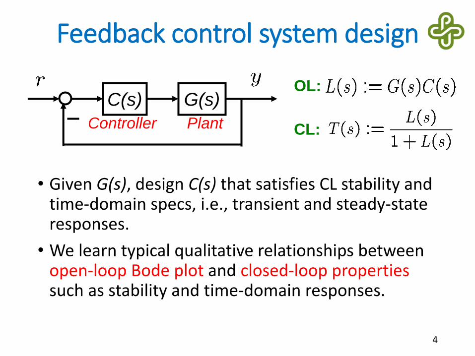
Feedback control system design
• Given G(s), design C(s) that satisfies CL stability and time-domain specs, i.e., transient and steady-state responses.
• We learn typical qualitative relationships between open-loop Bode plot and closed-loop propertiessuch as stability and time-domain responses.
4
G(s)C(s)
PlantController
OL:
CL:

An advantage of Bode plot (review)
• Bode plot of a series connection G1(s)G2(s) is the addition of each Bode plot of G1 and G2.• Gain
• Phase
• We use this property to design C(s) so that G(s)C(s)has a “desired” shape of Bode plot.
5
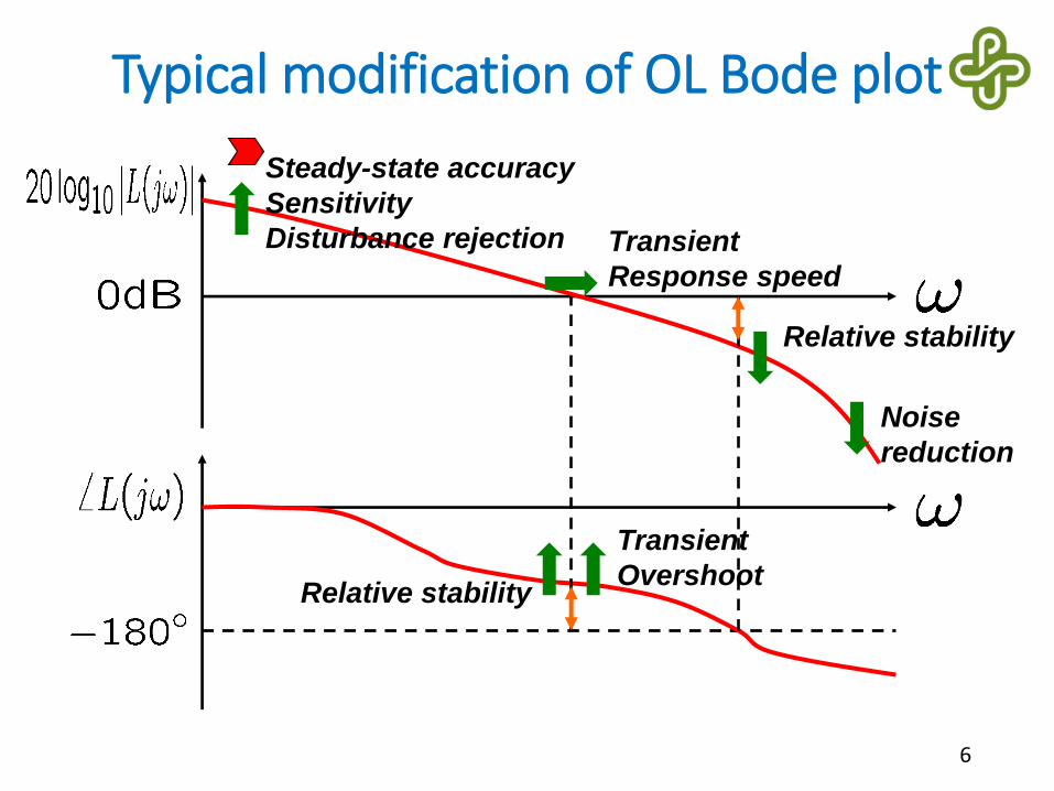
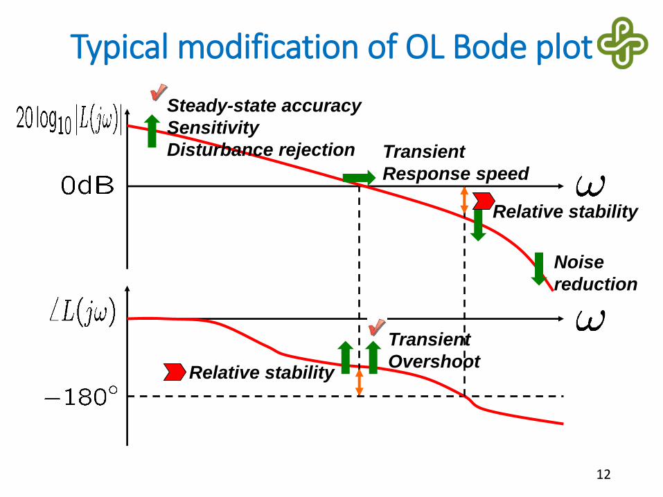
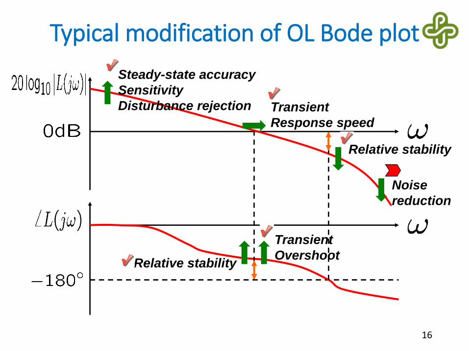
Typical modification of OL Bode plot
6
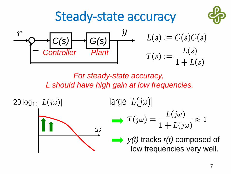
Steady-state accuracy
Sensitivity
Disturbance rejection
Noise
reduction
Transient
Response speed
Transient
OvershootRelative stability
Relative stability
Steady-state accuracy
7
G(s)C(s)
PlantController
For steady-state accuracy,
L should have high gain at low frequencies.
y(t) tracks r(t) composed of
low frequencies very well.

Steady-state accuracy (cont’d)
• Step r(t)
Increase
8
• Ramp r(t)
Increase
• Parabolic r(t)
Increase
For Kv to be finite,
L must contain
at least one integrator.
For Ka to be finite,
L must contain
at least two integrators.
<-20 <-40

Typical modification of OL Bode plot
9
Steady-state accuracy
Sensitivity
Disturbance rejection
Noise
reduction
Transient
Response speed
Transient
OvershootRelative stability
Relative stability

A second order example
• For illustration, we use the feedback system:
10
G(s)C(s)
PlantController

Percent overshoot
11
0 5 10 150
0.2
0.4
0.6
0.8
1
1.2
1.4
1.6
1.8
For small percent overshoot,
L should have larger phase margin.
10-1
100
101
-20
0
20
10-1
100
101
-180
-160
-140
-120
-100
CL step responseOL Bode plot
PM
Typical modification of OL Bode plot
12
Steady-state accuracy
Sensitivity
Disturbance rejection
Noise
reduction
Transient
Response speed
Transient
OvershootRelative stability
Relative stability

Relative stability
• We require adequate GM and PM for:• safety against inaccuracies in modeling
• reasonable transient response (overshoot)
• It is difficult to give reasonable numbers of GM and PM for general cases, but usually,• GM should be at least 6dB
• PM should be at least 45deg
(These values are not absolute but approximate!)
• In controller design, we are especially interested in PM (which typically leads to good GM).
13

Typical modification of OL Bode plot
14
Steady-state accuracy
Sensitivity
Disturbance rejection
Noise
reduction
Transient
Response speed
Transient
OvershootRelative stability
Relative stability

Response speed
15
0 5 10 150
0.2
0.4
0.6
0.8
1
1.2
1.4
100
-20
0
20
10-1
100
101
-180
-160
-140
-120
-100
For fast response,
L should have larger gain crossover frequency.
CL step responseOL Bode plot
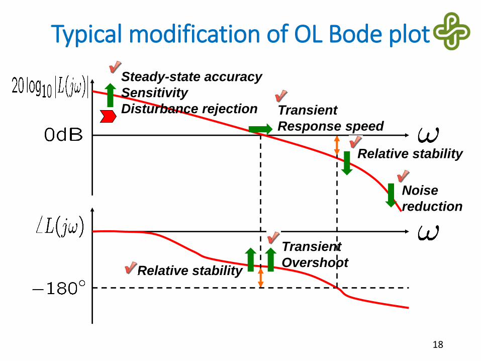
Typical modification of OL Bode plot
16
Steady-state accuracy
Sensitivity
Disturbance rejection
Noise
reduction
Transient
Response speed
Transient
OvershootRelative stability
Relative stability

Noise reduction
17
y(t) is not affected by n(t)
composed of high frequencies.
G(s)C(s)
PlantController
n(t): noise
y(t)
For noise reduction,
L should have small gain at high frequencies.
Typical modification of OL Bode plot
18
Steady-state accuracy
Sensitivity
Disturbance rejection
Noise
reduction
Transient
Response speed
Transient
OvershootRelative stability
Relative stability

Sensitivity reduction
• Sensitivity indicates the influence of plant variations (due to temperature, humidity, age, etc.) on closed-loop performance.
• Sensitivity function
19
For sensitivity reduction,
L should have large gain
at low frequencies.

Disturbance
• Unwanted signal
• Examples• Load changes to a voltage regulator
• Wind turbulence in airplane altitude control
• Wave in ship direction control
• Sudden temperature change outside the temperature-controlled room
• Bumpy road in cruise control
• Often, disturbance is neither measurable nor predictable. (Use feedback to compensate for it!)
20

Disturbance rejection
21
y(t) is not affected by d(t)
composed of low frequencies.
For disturbance rejection,
L should have large gain at low frequencies.
G(s)C(s)
PlantController
d(t): disturbance
y(t)
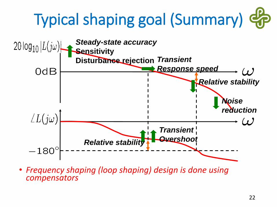
Typical shaping goal (Summary)
22
Steady-state accuracy
Sensitivity
Disturbance rejection
Noise
reduction
Transient
Response speed
Transient
OvershootRelative stability
Relative stability
• Frequency shaping (loop shaping) design is done using compensators

Summary
• System performance such as transient response and steady state error (time domain attributes) and sensitivity to plant variations and disturbance rejection are addressed by appropriate design in the frequency domain.
• This leads to a set of frequency domain specifications.
• These are specifications are on the loop gain, specifically, low frequency gain, bandwidth (unity gain crossover), phase margin and high frequency roll off.
• Next, steady state error.
23