ece 686 power systems modelling charalambos a...
TRANSCRIPT

ECE 686 Power Systems Modelling
Charalambos A. Charalambous Assistant Professor
Course Description
1

Power System Modelling Modelling power systems is an area of ongoing interest in the transmission management and control systems community. Continuing development is driven by:
•The traditional tasks of maintenance and management must be achieved with fewer resources. •Minimise Investment/Financial Risks.
The size of the associated infrastructure enforces logistic and other security/safety/cost related restrictions on large scale experiments and testing. Therefore it is prudent for engineers to adopt an alternative approach that utilises mathematically adequate models for computer simulations.
As a consequence, it is of major importance to be able to analyse any equipment incorporated in a power system plant, in a considerable detail, so that a close to optimum is achieved. This analysis becomes particularly important for large special purpose equipment where cut-and-try methods are impossible or prohibitively expensive.
2

Problem Based Learning What is problem based learning? Problem Based Learning is one of a group of learning strategies which are considered to be encompassed within Enquiry-Based Learning (EBL) which itself is defined as ‘’a broad umbrella term used to describe approaches to learning that are driven by a process of enquiry,’’ O’ Rourke and Kahn (2005).
Problem Based Learning is a process that has a number of features: The learning process is bi-directional and is mainly based on students and collaboration. The process is initiated by the presentation of a problem. The students are responsible for identifying what they need to learn and what information they need to find and what research, investigations and analysis they need to undertake in order to understand the problem and reach to a conclusion.
3

Intended Learning Outcomes Following your classes you should be able to: Acquire knowledge on how to approach various Power System Modeling tasks of industrial flavour. Understand the theoretical Principles of ECE – 796 : Power System Plant and Operation Use commercially available power system softwares. Appreciate the dynamics of Problem Based Learning.
4

Teaching Methodology
5
Case study will be initiated by a short presentation of the task. Short theoretical background and sources for further reading. Guided completion of the case study and directions to answer any
associated questions. Report describing the calculations, simulation results and
comprehensive answers to the questions.
In some cases some critical evaluation of the results and comparison with reality will be requested.
Assessment - Examination
6
Attendance: 5% Five Comprehensive Reports: 70% Final Exam (Laboratory Based): 25%

7
• Simulating Travelling Waves on Single Phase Transmission Lines – Theory
S R Z’
Y/2 Y/2 1 p.u LOAD Zc
• Travelling Wave Example (ATP Draw) – Simulation Model:
Case Study 1: Travelling Wave Theory in Transmission Lines

8
Case Study 2-3: Substation Plant Design Exercise It is tempting to only think of the steady state phase to earth and phase to phase
voltages when considering the dimensions of power system plant. In reality, dimensioning is often based on consideration of temporary overvoltages or transient voltages (both the slower switching voltage and the faster lightning voltage). In this exercise, you will examine the typical sources of abnormal voltages on the power system and investigate the impact that this has on dimensioning of equipment. This will be done using a mix of computer simulations (introducing you to the PSCAD and ATP package).
Exercise One – The Ferranti Effect Exercise Two – Ferroresonance Exercise Three – Travelling Wave Surge Impedance and Velocity Exercise Four – Simulation of Switching Overvoltages & Pre-Insertion Resistors Exercise Five – Simulation of Direct Lightning Strikes to Overhead Line Phase Conductors Exercise Six – Simulation of a back-flashover

9
Case Study 4: Mathematical Modeling of Lightning & Switching Impulses
The objective of this exercise is to model a lightning impulse waveform that will subsequently used in performing the insulation coordination study to protect a transformer.
Tasks: Analysis of Circuits in Laplace Domain. Modelling of Circuits using ATP and MATLAB.

10
Case Study 5: Cable Design and Simulations Cable Design Exercise: Given the following parameters and equations, produce an Excel spreadsheet and a matlab algorithm that can calculate the steady state current rating for a cable circuit made up using single phase cables XLPE/ paper designed to operate on a 33kV power system. Produce a graph showing the expected current rating for both XLPE and paper cables with cross-sectional areas between 150mm2 and 1000mm2 when the sheath is solidly bonded at both ends of the cable circuit.
XLPE Cable Paper Cable Power System Voltage 33kV 33kV Resistivity of Aluminium Conductor 2.8 x 10⁻⁸ Ω.m 2.8 x 10⁻⁸ Ω.m Packing/ Skin/ Proximity Effect Factor 0.9 0.9 Maximum Electric Field (During State State) 50 kV/cm 50 kV/cm Relative Permittivity 2.3 3.4 Tanδ 0.004 0.01 Required Sheath Cross Sectional Area 145mm2 145mm2 Resistivity of Aluminium Sheath 3.0 x 10⁻⁸ Ω.m 3.0 x 10⁻⁸ Ω.m Oversheath Material Thickness 2mm 2mm Thermal Resistivity of Insulation 3.5 Km/W 5.5 Km/W Thermal Resistivity of Oversheath 6.0 Km/W 6.0 Km/W Thermal Resistivity of Ground 1.2 Km/W 1.2 Km/W Ground Temperature 25oC 25oC Maximum Operating Temperature 90oC 65oC Cable Installation Format Flat Flat Spacing Between Cable Centres 50mm 50mm Cable Depth 1m 1m
Describe how the choice of cable insulation material has affected the current carrying capability of each power cable. In addition, show how the effective current carrying varies for cable length between 100 m and 200 m.

11
Case Study 6: Cable Design and Simulations Electric Performance of a three phase Cable using a F.E.A Software:
Calculate Electric Field Calculate Cable’s Capacitance

12
Case Study 7: Cable Design and Simulations
Transferring Real (Manufacturing) Cable Design Data into a Simulation Model

13
Case Study 8: Power Transformer Design Mathematical Model of the core non-linearity of a five limb transformer, excluding the effect of hysteresis.
l1
l2W2
T
W1
W3
l3
570
2220570
570
1625945
890 890
5701625
945 9453360
9005
0 10 20 30 40 50 600
10
20
30
40
50
60
70
Peak current [A]
Peak
flux
-Lin
kage
[Wb-
T]
Exponent, P=23Exponent, P=25Exponent, P=27Real Data at Tertiary
Extrapolate the highly saturated regions in order to represent the non-linearity of the core in these sections.
Geometrically Accurate Core Design
Material Characteristics
14
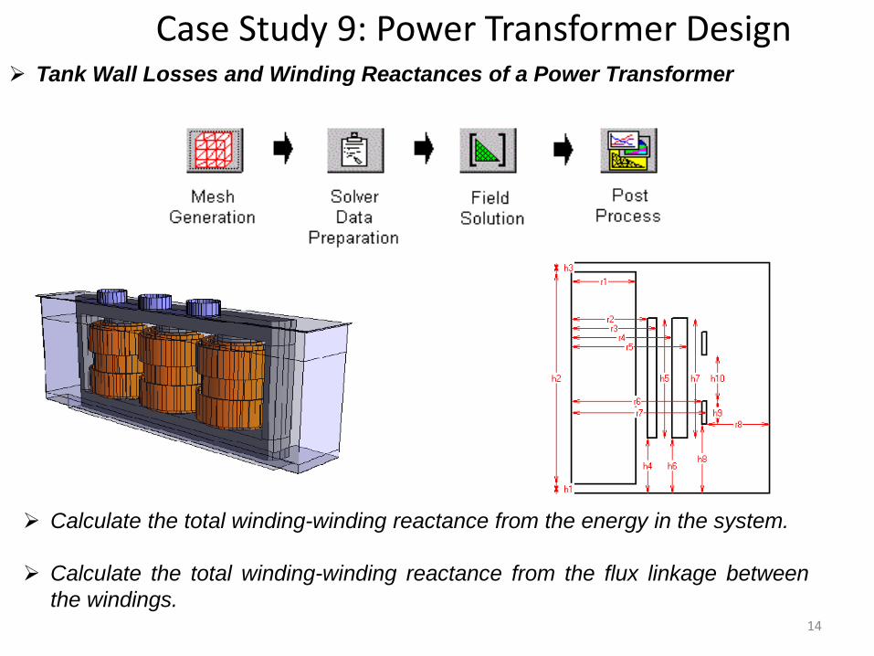
Case Study 9: Power Transformer Design Tank Wall Losses and Winding Reactances of a Power Transformer
Calculate the total winding-winding reactance from the energy in the system.
Calculate the total winding-winding reactance from the flux linkage between the windings.

15
Case Study 10: Power Transformer Design Time Domain Flux Density Variation within a three limb transformer core
Balanced Exciting Conditions
Unbalanced Exciting Conditions

16
Case Study 11: Transformer Design Transferring Real Test Repost Data into a Simulation Model

Case Study 12: Transformer De-energisation Study For A Substation Commissioning
17
In the process of commissioning a substation, the local authorities has discovered a problem when de-energising two 132/33 kV 45/90 MVA grid transformers. The transformers are configured to be energised /de-energised by circuit breakers at the substation via 11.5 km long 132 kV polymeric cables. An audible "clunk" noise can be heard when the transformer is de-energised, when the cable is connected to the transformer. The purpose of this exercise is: Identify the nature of the problem Identify the critical condition that creates the problem Formulate a simulation model including the grid transformer, the cable and the circuit breaker, in the ATP software package.

18
Case Study 13: Earthing Design and L.P for Solar Applications
Earthing System and Performance for open field PV systems without substations
Isolated Lightning Protection System
Non-Isolated Protection System

Essential Auxiliary Tools
19
In every lab session you should possess the following: A standard calculator. A log book. A memory stick/or a portable hard drive.
A hard case folder
A personal laptop can be used if available

Softwares to be used: ATP
20
Alternative Transient Program (ATP) ATP is a universal program system for digital simulation of transient phenomena of electromagnetic as well as electromechanical nature. With this digital program, complex networks and control systems of arbitrary structure can be simulated.
ATP has extensive modelling capabilities and additional important features besides the computation of transients. It has been continuously developed through international contributions over the past 20 years.
UCY posses a full licence and access to secure website server:
•Host name: http://www.eeug.org/files/secret. •Username and Password for downloading manuals and reference documents can be provided upon agreement with your Class Leader.

21
Softwares to be used: PSCAD PSCAD®, also known as PSCAD®/EMTDC™, is a powerful electromagnetic time domain transient simulation environment and study tool. Commercially available since 1993, PSCAD® is the result of continuous research and development since 1988. It continues to be developed to meet the growing demand for more power and convenience.
PSCAD Student Version has been locally installed in laboratories computers.
Download from:
•https://pscad.com/products/pscad/free_downloads/

22
Softwares to be used: SLIM
SLIM •SLIM Electromagnetic Engineering software is Alstom GRID own electromagnetic field analysis software. •SLIM Electromagnetic Engineering is a suite of software for the analysis of electromagnetic (EM) fields.
•Its modular arrangement contains facilities for mesh generation, field solution and post processing. •Uses 2D, axi-symmetric and 3D geometries. Modeling encompasses static, dynamic and transient studies, motion (rotating machines, actuators), non-linearity, eddy currents. •With development driven by the needs of experienced product designers and users and AREVA T&D’s product units, SLIM’s extensive functionality is focused on the analysis of T&D equipment. •It is the product of a highly experienced team of electrical engineers, mathematicians and software engineers.

23
Contact Details
Charalambos A. Charalambous Office: Green Park 412 Tel: 22892285 Email: [email protected]