ece 477 design review team 13 spring 2006 elmer chao (not pictured), matt cozza (not pictured), joe...
TRANSCRIPT

ECE 477 Design Review ECE 477 Design Review Team 13 Team 13 Spring 2006 Spring 2006
Elmer Chao (not pictured), Matt Cozza (not pictured), Joe Waugh (not pictured), Evan Zelkowitz (not pictured)

OutlineOutline• Project overview Project overview • Project-specific success criteriaProject-specific success criteria• Block diagramBlock diagram• Component selection rationaleComponent selection rationale• Packaging designPackaging design• Schematic and theory of operationSchematic and theory of operation• PCB layoutPCB layout• Software design/development statusSoftware design/development status• Project completion timelineProject completion timeline• Questions / discussionQuestions / discussion
Project OverviewProject OverviewOur team is designing a telemetry board for the Our team is designing a telemetry board for the
Purdue Solar Racing teamPurdue Solar Racing team
• Interfaces with Motor Controller, Battery Interfaces with Motor Controller, Battery Pack, Packet Modem, PowerPoint trackers, Pack, Packet Modem, PowerPoint trackers, and Driver Interface System.and Driver Interface System.
• Gathers temperature, acceleration, and GPS Gathers temperature, acceleration, and GPS data.data.
• Transfers information out to Driver Interface Transfers information out to Driver Interface System and Packet Modem.System and Packet Modem.

Project-Specific Success CriteriaProject-Specific Success Criteria
• An ability to monitor vehicle temperature (and An ability to monitor vehicle temperature (and generate an alert message if out-of-range).generate an alert message if out-of-range).
• An ability to log (time stamp) vehicle acceleration An ability to log (time stamp) vehicle acceleration data.data.
• An ability to function as the local CAN bus master.An ability to function as the local CAN bus master.• An ability to generate vehicle status reports (and An ability to generate vehicle status reports (and
transmit them over a packet modem).transmit them over a packet modem).• An ability to bridge data communication between the An ability to bridge data communication between the
CAN bus and multiple RS-232 ports.CAN bus and multiple RS-232 ports.

µP(PIC18F)
Temperature Sensor
CA
N (x4)
Motor Controller Battery System Packet Modem
Single-Axis Accelerometer (Y)
12v to 5v
SPI-to-UART(SCI16IS752)
Quad RS-232Transceiver
(MAX238)
SPI-to-UART(SCI16IS752)
RS-232
Unused I/O Connector
CAN
A/D
A/D
I/O
MTE
ICP
Flash
GPS
Single-Axis Accelerometer (Z)
Single-Axis Accelerometer (X)
A/D
A/D
SPI
Block Diagram
PowerPoint Trackers
Driver Interface System
Not part of Telemetry System
CAN Bus

Component Selection RationaleComponent Selection Rationale
• Microcontroller – PIC18F4680Microcontroller – PIC18F4680• SPI to UART - SC16IS752 / MAX238SPI to UART - SC16IS752 / MAX238• Power – MAX1684 / LT1121Power – MAX1684 / LT1121• Accelerometers – 1260D/2260DAccelerometers – 1260D/2260D• GPS Unit – Garmin GPS18GPS Unit – Garmin GPS18

Packaging DesignPackaging Design
• Size not a constraintSize not a constraint• Needed to be lightweightNeeded to be lightweight• Actual Dimensions: 5in x 7in x 3in Actual Dimensions: 5in x 7in x 3in • Material: ABS PlasticMaterial: ABS Plastic
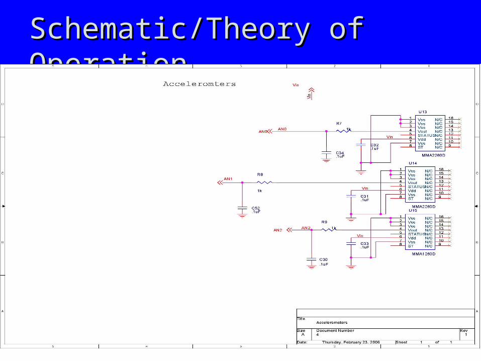
Schematic/Theory of OperationSchematic/Theory of Operation

Schematic/Theory of OperationSchematic/Theory of Operation

Schematic/Theory of OperationSchematic/Theory of Operation

Schematic/Theory of OperationSchematic/Theory of Operation

PCB LayoutPCB Layout
Top Copper Bottom Copper No Pours
1. Analog
2. Power

PCB Layout – Power RegulatorsPCB Layout – Power Regulators1. 3.3v output capacitor close to regulator
2. 5v output capacitor and inductor close to regulator
3. 5v input capacitor close to regulator
4. Power layout entirely single sided, with ground plane underneath

PCB Layout – Analog CircuitsPCB Layout – Analog Circuits
1. Single sided analog circuit layout, with ground plane underneath
2. Analog circuitry separated from other modules
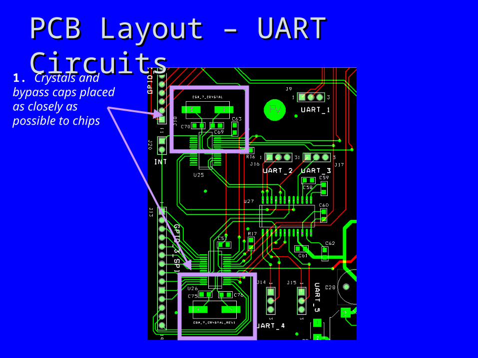
PCB Layout – UART CircuitsPCB Layout – UART Circuits1. Crystals and bypass caps placed as closely as possible to chips

PCB Layout - ProcessorPCB Layout - Processor
1. Crystals and bypass caps placed underneath the processor
Software Design/Development StatusSoftware Design/Development Status
• Started work with MPLab simulatorStarted work with MPLab simulator• Laying out ground rules for CAN protocolLaying out ground rules for CAN protocol
– Using OpenCAN implementation from Using OpenCAN implementation from MicroChip. High Level protocol that is MicroChip. High Level protocol that is easily expanded.easily expanded.

Project Completion TimelineProject Completion Timeline
• PCB finalized this weekPCB finalized this week• Software design considerations and planning Software design considerations and planning
to be completed by end of spring breakto be completed by end of spring break• First phase development of software needs First phase development of software needs
to be completed by two weeks after spring to be completed by two weeks after spring breakbreak

Questions / DiscussionQuestions / Discussion