ece 4750 computer architecture, fall 2020 lab 4: multicore
TRANSCRIPT

ECE 4750 Computer Architecture, Fall 2020Lab 4: Multicore Processor
School of Electrical and Computer EngineeringCornell University
revision: 2020-11-13-00-04
"Let us open the Pandora’s box of parallel programming."
In this lab, you will be composing the processor, cache, and network you have designed through-out the semester to create the baseline design (a single-core processor with its own instruction anddata cache) and the alternative design (a simple multicore processor with private instruction cachesand a shared, banked data cache). You will also have a chance to write a single-threaded and multi-threaded sorting microbenchmark in C, explore the compiled and assembled binary, and run theseprograms on the baseline and alternative designs. You are required to implement the baseline andalternative designs, verify the designs using an effective testing strategy, and perform an evalua-tion comparing the two implementations. As with all lab assignments, the majority of your gradewill be determined by the lab report. You should consult the course lab assignment assessmentrubric for more information about the expectations for all lab assignments and how they will beassessed.
Some unique features of this lab assignment include its emphasis on structural composition to in-crementally create a relatively complex system based on thoroughly unit-tested subsystems, and itsemphasis on software/hardware co-design such that students must understand the software applica-tion, hardware/software interface, and hardware microarchitecture. You will be using various incre-mental compositions to: (1) test composing the network we provide you with, with special adaptersto build memory networks suitable for sending memory requests and receiving memory responses;(2) test composing the memory networks and the cache from Lab 3 to build a shared, banked datacache; and (3) test the entire single core and multicore systems. You will be using the standardRISC-V cross-compiler to compile C programs down to a RISC-V binary suitable for execution onour RISC-V simulators. You will be writing your own single-threaded quicksort microbenchmark,as well as a multi-threaded sorting microbenchmark that uses an algorithm of your choice. You willhave an opportunity to improve the performance of your final multi-threaded sorting microbench-mark through either software or hardware improvements.
This lab is designed to give you experience with:
• composition of simpler subsystems to create more complex systems;• programming single- and multi-threaded C programs;• software/hardware co-design;• design principles including modularity, hierarchy, encapsulation, and regularity;• design patterns including latency insensitive message interfaces;• agile design methodologies including incremental development and test-driven development;• computer architecture evaluation methodologies based on architecture-level statistics;
This handout assumes that you have read and understand the course tutorials and the lab assessmentrubric. To get started, you should access the ECE computing resources and you have should haveused the ece4750-lab-admin script to create or join a GitHub group. If you have not do so already,source the setup script and clone your lab group’s remote repository from GitHub:
1

ECE 4750 Computer Architecture, Fall 2020 Lab 4: Multicore Processor
% source setup-ece4750.sh% mkdir -p ${HOME}/ece4750% cd ${HOME}/ece4750% git clone [email protected]:cornell-ece4750/lab-groupXX.git
where XX is your group number. You should never fork your lab group’s remote repository! If youneed to work in isolation then use a branch within your lab group’s remote repository. If you havealready cloned your lab group’s remote repository, then use git pull to ensure you have any recentupdates before running all of the tests. You can run all of the tests in the lab like this:
% cd ${HOME}/ece4750/lab-groupXX% git pull --rebase% mkdir -p sim/build% cd sim/build% py.test ../lab5_mcore
Since we provide you the single core composition, the memory network compositions, and theshared, banked data cache composition, many of the tests may pass if the subsystems from yourprevious labs are completely functional. For this lab, you will be working in the lab5_mcore subpro-ject which includes the following files:
• SingleCorePRTL.py PyMTL single-core composition• SingleCoreRTL.py Verilog single-core composition• SingleCoreVRTL.v Wrapper to choose which RTL language
• MsgAdapters.py PyMTL adapters to convert between MemMsg and NetMsg• MsgAdapters.v Verilog adapters to convert between MemMsg and NetMsg• CacheNetPRTL.py PyMTL CacheNet module• CacheNetVRTL.v Verilog CacheNet module• CacheNetRTL.py Wrapper to choose which RTL language• MemNetPRTL.py PyMTL MemNet module• MemNetVRTL.v Verilog MemNet module• MemNetRTL.py Wrapper to choose which RTL language• McoreDataCachePRTL.py PyMTL data cache system composition• McoreDataCacheVRTL.v Verilog data cache system composition• McoreDataCacheRTL.py Wrapper to choose which RTL language• MultiCorePRTL.py PyMTL multi-core composition• MultiCoreVRTL.v Verilog multi-core composition• MultiCoreRTL.py Wrapper to choose which RTL language
• elf.py Utils for reading/writing ELF binary files• isa-sim ISA simulator for testing programs• score-sim Single-core simulator for evaluation• mcore-sim Multicore simulator for evaluation• __init__.py Package setup
• test/TestNetCacheSink.py Yet another special test sink• test/CacheNetRTL_test.py Test for CacheNet• test/MemNetRTL_test.py Test for MemNet• test/McoreDataCacheRTL_test.py Test for data cache system
2

ECE 4750 Computer Architecture, Fall 2020 Lab 4: Multicore Processor
• test/harnesses.py Test and simulation harnesses• test/inst_csr.py CSR tests for multi-core• test/inst_jal.py Staff jal tests• test/inst_mul.py Staff mul tests• test/inst_sw.py Simple sw tests for multi-core• test/SingleCoreRTL_test.py Test for single-core composition• test/MultiCoreRTL_test.py Test for multi-core composition• test/__init__.py Package setup
1. Introduction
Ever since transistor scaling has stopped delivering exponential growth in performance within sim-ilar area and power constraints, computer architects have tried different ways to scale the processorperformance, beyond simply exploiting more instruction-level parallelism (ILP). Two promising ap-proaches have been to exploit data-level parallelism (DLP) and/or thread-level parallelism (TLP).Multicore processors (a.k.a., chip multiprocessors) exploit TLP by allocating different threads withina single program to the different cores within the chip. Ideally, fully parallelizing an application onP processors leads to about P× speedup.
However, multicore designs also have their drawbacks. First of all, it is not possible to fully par-allelize most applications, and serial portions of the code can quickly dominate the execution time.In this course we are using a simplified multicore system to ensure correct execution, but a realisticmulticore system must manage coherence, consistency and synchronization. Finally, the multicoredesign definitely has higher hardware complexity and more hardware overall.
In this lab, you will get the chance to explore some of these trade offs using a single core with its owninstruction and data cache, and a quad-core system with private instruction caches and a shared,banked data cache.
We will reuse the assembly tests for a representative subset of instructions (since the simulation timeis increased due to more complex models) from Lab 2 to test the single-core system. To test themulti-core composition, we introduce an extension to the assembly test methodology from Lab 2that enables initializing multiple test sources and sinks (one per core). In the spirit of incrementaldesign, we will work with these sub-compositions first: CacheNet, MemNet, and McoreDataCache. Weunit test them, and reuse them to build larger components.
Unlike previous labs, this lab has significant portion of software. We organize files as follows:lab-groupXX is the top level lab repo you have been using in this course, lab-groupXX/sim con-tains PyMTL or Verilog designs and unit tests. lab-groupXX/app is the microbenchmark directoryyou will be working in for the software side of this lab. We will be using the standard RISC-V cross-compiler which compiles C programs to the full RISC-V ISA, and a modular C++ build system tosimplify running the compiler. Here is how we build applications:
% cd ${HOME}/ece4750/lab-groupXX% mkdir app/build% cd app/build% ../configure --host=riscv32-unknown-elf% make
3

ECE 4750 Computer Architecture, Fall 2020 Lab 4: Multicore Processor
Figure 1: SingleCore – The SingleCore module as a whole, is hooked up to the test source, test sink,and test memory for testing and evaluation. Each bundle of the three arrows is a msg/val/rdy portbundle. The ports with inclined names are the top-level ports that SingleCore expose.
2. Baseline Design
For the baseline design, we are going to compose the processor from Lab 2 and two caches fromLab 3 (one as the instruction cache, and the other as the data cache). This will give you a simple yetrealistic single-core system as the hardware part of the baseline. The software counterpart is a scalarquicksort program.
We have provided the composition in SingleCorePRTL.py/SingleCoreVRTL.v. Note that this designdoes not need a network. Although we give this file to you, you need to look into and understand thecomposition and the way we count cache miss/access statistics. We set num_banks=0 for both cachessince we are only in a single-core configuration. We connect 0 to core_id port and we set num_cores=1for the processor. These two parameters will be very important in your multicore processor, and areexplained in depth in the next section.
The composition and the connections of the single core system will look like the Figure 1. The cacherequest and response ports of the caches connect to the respective i/dcache ports of the processor,while the memory request and response ports connect to outside facing i/dmemreq/sp ports asshown. Note that the data bitwidth from processor to caches is 32 bits, while the data bitwidth fromthe caches to the test memory is the full cache line, which is 128 bits in this design.
As the software part of the baseline, you are required to implement scalar quicksort algorithm in Cin the quicksort_scalar() function of app/ubmark/ubmark-quicksort.c. Currently, this functiononly has a template which copies the source array to destination, and your task is to sort the srcarray using the quicksort algorithm and write the result to destination. This file also contains verifi-cation logic to ensure the correctness of your algorithm implementation. You are welcome to consult
4

ECE 4750 Computer Architecture, Fall 2020 Lab 4: Multicore Processor
Figure 2: Alternative design block diagram – The alternative design consists of four processors, fourprivate I-caches, a four-banked shared D-cache, and several networks to route dmem request/re-sponse from the processors and the D-cache, and refilling both the I-cache and the D-cache. Notethat each network shown in the diagram is actually two networks: one for request and the other forresponse.
textbooks or online resources to learn more about quicksort, but you should cite these resources.Copying code is not allowed; you should write it on your own.
3. Alternative Design
The alternative design is to implement the multicore system and run a parallel sorting implemen-tation on it. The multicore system consists of four processors, four instruction caches (one privateinstruction cache per processor), four data cache banks that are shared across all four cores, and four-port networks to interconnect the subsystems. You are free to choose which design in the previouslabs to use; while there is always a trade-off between the baseline design and the alternative design,your goal should be to achieve the highest performance possible. Choosing an appropriate networkfor the cache net is particularly important.
5

ECE 4750 Computer Architecture, Fall 2020 Lab 4: Multicore Processor
Figure 3: CacheNet – The CacheNet module as a whole, is hooked up to the test sources, test sinks,and four-port test memory for unit testing. Each arrow is actually a msg/val/rdy port bundle whosedirection is the msg/val direction. Each "U" and "D" is an adapter which takes care of both therequest port and the response port, and has its own adapter id. The ports with inclined names arethe top-level ports that CacheNet exposes.
Figure 2 illustrates the system structure at a high level. Keep in mind that we will take an incre-mental design approach to build the whole system. We have provided you with the following sub-compositions with unit tests.
• CacheNet: the request/response network pair connecting four processors and four cache banks.• MemNet: the request/response network pair connecting four caches and one main memory port.• McoreDataCache: CacheNet + four cache banks + MemNet = the whole data cache subsystem
3.1. CacheNet: The Network Between Processors and Data Cache Banks
The most confusion often comes from this question: how do we actually compose the cache with thenetwork? Figure 3 shows the diagram of the CacheNet that we are going to use to interconnect thefour processors and the four data cache banks.
You can see from the diagram that we instantiate two networks (a request network and a responsenetwork). There are several important adapters to convert between memory messages and networkmessages at each network terminal. "U" corresponds to UpstreamMsgAdapter, where "D" corre-sponds to DownstreamMsgAdapter. The reason why we call them "upstream" and "downstream"is the following. Intuitively, the processor is the upstream, and the main memory (here it’s cache) isthe downstream which passively accepts memory request and emits memory response. As a result,the UpstreamMsgAdapter is meant to be put at the processor side of the network, and vice versa.
In general, the UpstreamMsgAdapter has two functions, one for the request network and the otherfor the response network:
• Accept a memory request and turn it into a network message whose payload is the request.• Turn a network message back to a memory response by just throwing away the header.
In contrast, the DownstreamMsgAdapter has the following two functions:
6

ECE 4750 Computer Architecture, Fall 2020 Lab 4: Multicore Processor
31 10 9 6 5 4 3 0
tag index bank offset
Figure 4: Memory Address Formats With Banking – Addresses for the data cache include two bankbits which are used to choose which bank to send the memory request; in other words, the bankbits are used as the destination field when converting a memory request message into a networkmessage.
Figure 5: MemNet – The MemNet module as a whole, is hooked up to the test sources, test sinks,and single-port test memory for unit testing. Each arrow is actually a msg/val/rdy port bundlewhose direction is the msg/val direction. Each "U" and "D" is an adapter which takes care of boththe request port and the response port, and has its own adapter id. The ports with inclined namesare the top-level ports that MemNet exposes.
• Turn a network message back to a memory request by throwing away the header.• Accept a memory response and turn it into a network message whose payload is the response.
You may ask where the source and the destination in the header are from when UpstreamMsgAdapterturns a memory request into a network message. Recall from Lab 3 that in a multi-banked cache de-sign, we use a set of “bank bits” so that cache lines are interleaved across different cache banks. Fig-ure 4 illustrates which bits are used for the four-banked data cache. In CacheNet, the UpstreamMsgAdapterextracts this bank index from the address of the memory message from processor and uses it as thedestination field in the header (the source field is basically the processor/adapter id). Also, don’tforget that the corresponding cache response generated by a cache bank needs to be sent back to thecorrect processor. To determine who had sent the cache request originally, we use some high bitsof the opaque field in the memory message to store the processor/adapter id. The cache and thememory system are required to preserve the opaque field throughout the memory system. Whenthe DownstreamMsgAdapter gets a cache response, it will extract the destination adapter/processorid from the opaque field, possibly restore the previous opaque field value, and then send the cacheresponse into the response network.
7

ECE 4750 Computer Architecture, Fall 2020 Lab 4: Multicore Processor
Figure 6: MCoreDataCache – The McoreDataCache module as a whole, is hooked up to the testsources, test sinks, and single-port test memory for unit testing. Each arrow is actually a msg/-val/rdy port bundle whose direction is the msg/val direction. We omit the details inside MemNet andCacheNet but show the port names to match the previous diagrams. The ports with inclined namesare the top-level ports that this module exposes.
3.2. MemNet: The Network Between Caches and Main Memory
Unlike the CacheNet, the MemNet only uses one output terminal, but has four input terminals. Figure 5shows the diagram of the MemNet. In the MemNet, we use a different mode for the UpstreamMsgAdapterwhich always inserts 0 into the destination field. The rest of the module works in the same way asCacheNet. We can use the MemNet as the refill networks for the instruction caches and the data-cachebanks, since four caches/banks need to send requests to one main memory port.
3.3. McoreDataCache: The Data Cache Subsystem
We compose the CacheNet, MemNet, and four cache banks to create the complete shared, banked data-cache subsystem. We set num_banks=4 for each data cache to ensure they correctly handle the bankbits. Figure 6 shows the diagram of McoreDataCache module.
3.4. MultiCore: The Multicore Processor System
Note that we provide you the CacheNet, MemNet, and McoreDataCache compositions. You are respon-sible for creating the final composition with four processors, four private instruction caches, and theshared, banked data-cache subsystem to create the complete multicore system (see Figure 7). We in-stantiate four processors with num_cores=4 and connect 0, 1, 2, 3 respectively to the core_id port ofeach processor. The details of how we use these two parameters is discussed in the next subsection.We set num_banks=0 for each of the instruction cache since they are private caches and not banked.
8

ECE 4750 Computer Architecture, Fall 2020 Lab 4: Multicore Processor
Figure 7: MultiCore – The MultiCore module as a whole, is hooked up to a dual-port test memory,four test sources and four test sinks. Note that to not to make the diagram too crowded, we omit theproc2mngr and mngr2proc port names both at the boundary of Multicore as well as in the processor.Each arrow is actually a msg/val/rdy port bundle whose direction is the msg/val direction. Theports with inclined names are the top-level ports that MultiCore exposes.
3.5. Software Side of Things
“Here Be Dragons!”
In addition to building the multicore composition, you also need to write a parallel sorting program.Before we jump into the software part, let’s demystify the csrr and csrw instructions whose im-plementations have already been provided to you in Lab 2. Here we explain the num_cores andcore_id control/status registers (CSRs) which are very important for this section, and in Section 5we will explain the stats_en CSR. See the TinyRV ISA manual for more details http://www.csl.cornell.edu/courses/ece4750/handouts/ece4750-tinyrv-isa.txt.
• By executing csrr x1, 0xF14, the processor puts the core id into register x1, and then one corecan differentiate itself from the others. For example, when we want processor 0 to process a[0],processor 1 to process a[1], processor 2 to process a[2], and processor 3 to process a[3], we canjust write a[core_id] in the program after we retrieve core_id. Similarly, to ensure only one ofthe processors is executing a serial part of the code, in the program we can compare the core id to0, and only then execute the given code block.
• By executing csrr x1, 0xFC1, the processor puts the number of cores into register x1. This isvery useful when we want to distribute the work evenly across multiple cores. For instance,
9

ECE 4750 Computer Architecture, Fall 2020 Lab 4: Multicore Processor
to parallelize work on an array by dividing and assigning a part of this array to each core, theprogram can then divide the total number of elements by the number of cores, to get the blocksize for each core.
You are free to implement any parallel sorting algorithm. This is a non-trivial task since there aremany trade-offs in terms of amount of parallelism, locality, and load balancing. It can be quitechallenging to parallelize quicksort directly. We recommend you implement a bottom-up hybridmergesort/quicksort algorithm. Divide the input array into four blocks. Each core can use the se-rial quicksort algorithm to sort its block. Then have core 0 merge the four blocks using mergesort.You are welcome to consult textbooks or online resources to learn more about different sorting al-gorithms, but you should cite these resources. Copying code is not allowed; you should write it onyour own.
We provide you a very light-weight threading library, called bthread. Note that we use thread andcore interchangeably in this lab since each core has only one thread. We call core 0 the master core andthe other cores the worker cores. Figure 8 illustrates how to use the bthread library to implement aparallel vector-vector add microbenchmark that makes use of two cores. The bthread_init functionsets up the library and must be called at the beginning of the main function. All four cores enterthe bthread_init function; core 0 will exit the function while the remaining three worker cores williterate in a worker loop waiting for work. The master core can spawn work onto a worker coreby using the bthread_spawn function, where the first argument is the ID of the core (thread) wewant spawn to, the second argument is the function pointer we want the worker core to execute,and the final argument is a pointer to a structure that holds the arguments the worker core shoulduse to do the work. The bthread_join function will cause a core to wait for given worker core.We provide you with four multi-threaded microbenchmarks to show how to use bthread library toparallelize single-threaded microbenchmarks. You may also want to look at the implementation ofeach bthread library in app/common/bthread.cc
A simple way to use the bthread library to implement the hybrid mergesort/quicksort mentionedabove is to divide the input array into four blocks, create four argument structures, use a bthread_spawnto spawn work onto cores 1–3, have core 0 also do some work, then core 0 can use a join to wait forcores 1–3 to finish, and core 0 can do the final merge.
Besides, we provide you with some additional features to facilitate debugging. Similar to what nor-mal printf, putchar and puts in C does, you can use wprint and wprintf function as the followingexamples to print char, string, or number to the terminal. The reason why we have to put "L" beforethe string literal is because our TinyRV2 processor only support full-word lw/sw. As a result we haveto use wchar_t which brings the "L" prefix. Note that the simulator only looks at Core 0’s wprint(f)messages.
wprint( L’a’); wprint( L’b’); wprint( L’c’);wprint( L"abc" );wprintf( L"number=%d, char=%C, string=%S", 42, L’a’, L"abc" ) # capital C and S
4. Testing strategy
Since this lab has an emphasis on both composition on the hardware side and parallel program-ming on the software side, we have provided you with basic tests and random tests to test all ofthe incremental compositions in the alternative design, and instruction tests for both the single- andmulti-core systems.
10

ECE 4750 Computer Architecture, Fall 2020 Lab 4: Multicore Processor
1 typedef struct {2 int* dest; // pointer to dest array3 int* src0; // pointer to src0 array4 int* src1; // pointer to src1 array5 int begin; // first element this core should process6 int end; // (one past) last element this core should process7 } arg_t;8
9 void vvadd_mt( void* arg_vptr )10 {11 // Cast void* to argument pointer.12 arg_t* arg_ptr = (arg_t*) arg_vptr;13
14 // Create local variables for each field of the argument structure.15 int* dest = arg_ptr->dest;16 int* src0 = arg_ptr->src0;17 int* src1 = arg_ptr->src1;18 int begin = arg_ptr->begin;19 int end = arg_ptr->end;20
21 // Do the actual work.22 for ( int i = begin; i < end; i++ )23 dest[i] = src0[i] + src1[i];24 }25
26 int main( int argc, char* argv[] )27 {28 // Initialize bare threads (bthread).29 bthread_init();30
31 // This array will be where the results are stored.32 int dest[size];33
34 // Start counting stats.35 test_stats_on();36
37 // Create two argument structures that include the array pointers and38 // what elements each core should process.39 arg_t arg0 = { dest, src0, src1, 0, size/2 };40 arg_t arg1 = { dest, src0, src1, size/2, size };41
42 // Spawn work onto core 143 bthread_spawn( 1, &vvadd_mt, &arg1 );44
45 // Have core 0 also do some work.46 vvadd_mt( &arg0 );47
48 // Wait for core 1 to finish.49 bthread_join(1);50
51 // Stop counting stats52 test_stats_off();53
54 // Core 0 will verify the results.55 if ( bthread_get_core_id() == 0 )56 verify_results( dest, ref, size );57
58 return 0;59 }
Figure 8: Simple Parallel Vector-Vector Add Microbenchmark for Two Cores
11

ECE 4750 Computer Architecture, Fall 2020 Lab 4: Multicore Processor
To test the single-core system with one instruction cache and one data cache, we will reuse the as-sembly tests for a representative subset of the instructions in Lab 2. We have already done extensiveunit testing in Lab 2, so our goal in Lab 4 is to focus on those tests that might expose bugs in thesingle- and multi-core compositions. We test the following instructions.
• CSR : csrr, csrw• Reg-Reg : add, mul• Reg-Imm : addi• Memory : lw, sw• Jump : jal• Branch : bne
As explained in Section 3, we incrementally build compositions, unit test them, and reuse them tobuild larger components such as the McoreDataCache and the MultiCore.
We reuse the test cases in Lab 3 to test the CacheNet and the McoreDataCache since the input messagesof these two modules are basically cache requests. The difference is that now we have four sourcesand four sinks which means that we will put requests/responses in each of the test source/sinkpair, and we have to use TestNetCacheSink to allow both out-of-order delivery and ignoring thecache test bits. The MemNet tests reuse the messages of TestMemory tests since the input of MemNet isessentially memory requests.
We also test the multicore composition using the same subset of instructions, except for sw and csr. Insw test cases there might be data races when different cores are trying to store/load data to the sameaddress. Depending on the each core’s progress, a core might read the data that has already beenoverwritten. For csr tests, all four cores have different core_ids. Thus, we introduce an extensionto our assembly test syntax which enables initializing multiple test sources and sinks. Here’s anexample of using the extended syntax.
# Example of using a list of valuescsrr x2, mngr2proc < {1,3,5,7}csrw proc2mngr, x2 > {1,3,5,7}
# Check numcores/coreidcsrr x2, numcorescsrw proc2mngr, x2 > 4csrr x2, coreidcsrw proc2mngr, x2 > {0,1,2,3}
Each core has its own test source/sink, so the first line initializes all four tests sinks with four differentvalues. Here are the commands to run the tests.
% cd ${HOME}/ece4750/lab-groupXX/sim/build% py.test ../lab5_mcore/% py.test ../lab5_mcore/test/SingleCoreRTL_test.py% py.test ../lab5_mcore/test/CacheNetRTL_test.py% py.test ../lab5_mcore/test/MemNetRTL_test.py% py.test ../lab5_mcore/test/McoreDataCacheRTL_test.py% py.test ../lab5_mcore/test/MultiCoreRTL_test.py
For the testing strategy, unlike the earlier labs, you are not required to come up with additional testcases. However, if you find that the provided test cases fail to capture a bug, you are encouraged to
12

ECE 4750 Computer Architecture, Fall 2020 Lab 4: Multicore Processor
design additional test cases, put them in the test files, and discuss them in your report. You can lookinto these test cases from previous labs and the PyMTL repo for inspiration.
Since this lab has an emphasis on both software and hardware, you definitely need to develop a testingstrategy for your single- and multi-threaded sorting microbenchmarks!. We recommend testing that yoursingle and multi-core sorting microbenchmarks work on arrays with different values and differentsizes.
Your report should briefly summarize the testing strategy used to test each subsystem in the firstfour labs, and also summarize the testing strategy that we provide you in this lab. You should gointo some nice detail on how we do the incremental testing, the single-core testing, and the multicoretesting in this lab. Make sure you include at least a paragraph about your software testing strategyfor the single- and multi-threaded sorting microbenchmarks. Discuss how all of this comes togetherto ensure we have a very sophisticated working design that can execute multi-threaded programswith realistic caches and networks.
5. Evaluation
We provide you with four single-threaded micro-benchmarks: vvadd, mfilt, cmult, and bsearch, whoseassembly sequences have been studied in Lab 2. All single-threaded microbenchmarks are in theapp/ubmark directory with their C source code and the dataset files. Take a look at all of them andfamiliarize yourself with what each one does.
In addition to the single-threaded benchmarks, we have provided multi-threaded benchmarks in theapp/mtbmark directory, which are the parallel version of the same microbenchmarks: vvadd, mfilt,cmult, and bsearch. All of these multi-threaded microbenchmarks statically partition the input for thenumber of cores (threads) that are available in the system.
5.1. Compile a Program and Investigate the Assembly Code
As the first step, we recommend you to compile microbenchmarks natively on x86/x64, instead ofdebugging them on your processor directly. We leverage a modular C++ build system to provideone-stop compilation solution in this lab, and hence compiling your program natively is very similarto compiling it for RISC-V. The only difference is the target host of the configure command, whichby default is x86/x64. Thus we don’t need to specify it for native compilation.
Below are the commands to build the programs natively. Note that we always create a temporarybuild directory to avoid cluttering up the source directories. We create one build directory for nativebuilds and a different build directory for RISC-V builds. Also note that You can also type makeubmark-vvadd to compile a specific benchmark.
% cd ${HOME}/ece4750/lab-groupXX/app% mkdir build-native% cd build-native% ../configure% make% make ubmark-vvadd
When you run your binaries natively, it will tell you if it passed or failed the verification. If you needfurther debugging, you can add printf statements, or use a debugger such as gdb. When you getyour app working, make sure you remove any printf statements because this is not supported onour TinyRV2 architecture.
13

ECE 4750 Computer Architecture, Fall 2020 Lab 4: Multicore Processor
After the native build succeeds with no error and hopefully passes the verification, you can com-pile the microbenchmarks for the TinyRV2 processor. The only difference is to specify the target toRISC-V by setting host to riscv32-unknown-elf. We usually term this compilation process as "cross-compilation".
% cd ${HOME}/ece4750/lab-groupXX/app% mkdir -p build% cd build% ../configure --host=riscv32-unknown-elf% make% make ubmark-vvadd
After the cross-compilation finishes, you can use objdump in the gcc toolchain to see the compiledassembly. Specifically, we have to use riscv32-unknown-elf-objdump which is part of the RISC-Vgcc toolchain. We have provided an alias for you to avoid typing these objdump options every time.You are also encouraged to change options and search online to learn about objdump. Here we usevvadd as an example, and we assume we have already built the microbenchmarks using the abovecommands.
% riscv32-unknown-elf-objdump -dC --no-show-raw-insn -Mno-aliases -Mnumeric ubmark-vvadd...00000248 <vvadd_scalar(int*, int*, int*, int)>:248: bge x0,x13,274 <vvadd_scalar(int*, int*, int*, int)+0x2c>24c: slli x13,x13,0x2250: add x13,x11,x13254: lw x15,0(x11)258: lw x14,0(x12)25c: addi x11,x11,4260: addi x12,x12,4264: add x15,x15,x14268: sw x15,0(x10)26c: addi x10,x10,4270: bne x11,x13,254 <vvadd_scalar(int*, int*, int*, int)+0xc>}274: jalr x0,x1,0
...% riscv32-objdump ubmark-vvadd # this command is an alias of the above command
Look familiar? Yes, the code sequence from pc=0x254 to pc=0x270 is almost identical to the vector-vector add code snippet we have seen throughout the course.
5.2. Run a Cross-Compiled Program
After making sure your application works natively, the second step is to run your program on thesingle-core or multi-core FL model. An ISA simulator, called isa-sim, supports both single- andmulti-core mode, and it will serve as the FL model in this lab. This simulator simply instantiates oneor four ProcFLs from Lab 2 based on the command line options.
It is important to debug your application on the ISA simulator before moving onto RTL. By defaultthe ISA simulator is single-core. The --mcore command line option makes the ISA simulator simulatea quad core. Here are the commands to run apps on the ISA simulator. Note that you can add--trace option to turn on line tracing.
14

ECE 4750 Computer Architecture, Fall 2020 Lab 4: Multicore Processor
% cd ${HOME}/ece4750/lab-groupXX/sim/% mkdir -p build% cd build% ../lab5_mcore/isa-sim ../../app/ubmark-vvadd
[ passed ]
In stats_en region:total_committed_inst = 811
% ../lab5_mcore/isa-sim --mcore --trace ../../app/mtbmark-vvadd...
[ passed ]
In stats_en region:total_committed_inst = 1400
core0_committed_inst = 341core1_committed_inst = 353core2_committed_inst = 353core3_committed_inst = 353
Here is one more recipe of isa-sim. Recall that in the iron law of processor performance, there is aterm called instruction per program. Although the ISA simulator doesn’t know the cycle count, itcan provide you with the number of committed instructions.
The most exciting step is to execute the native-tested and isa-simulated program on our SingleCoreor MultiCore system. We have provided you with two simulators, score-sim and mcore-sim tosimulate these two systems respectively. You can run the vvadd microbenchmark using the followingtwo simulation commands:
% cd ${HOME}/ece4750/lab-groupXX/sim/build% ../lab5_mcore/score-sim --stats ../../app/build/ubmark-vvadd% ../lab5_mcore/mcore-sim --stats ../../app/build/mtbmark-vvadd
The --stats option dumps all statistics during the stats_en region (explained in the next subsec-tion). The --trace displays the line tracing. The --dump-vcd enables .vcd waveform generation.
When you run a simulation, the simulator will also report whether the verification passed or failed.Make sure all of the verifications pass. If not, please go back to our systematic debugging strategy toisolate and resolve the error using test cases instead of debugging directly on simulator.
5.3. The Real Evaluation: Data and Statistics
Before we talk about statistics, let’s go back and think critically about what the performance meansfor our system with respect to a real binary executable file. We have done evaluations for Lab 1-4separately, so we might ask the following questions.
What is the difference between a compiled binary, and the assembly sequences we used in Lab 2?
15

ECE 4750 Computer Architecture, Fall 2020 Lab 4: Multicore Processor
A typical compiled program includes a lot of code to bootstrap, manage the stack, various librarycalls, etc. The code that we are interested in might be masked out by the uninteresting parts ofthis boilerplate code, so we only enable stats collection when we are actually in the piece of code ofinterest. To do so, we need to know about one more CSR.
• By executing addi x1, x0, {1 or 0}; csrr 0x7C1, x1, the processor set a special "stats" bit tohigh or low, to tell the simulator if the program has entered the "statistics enabled" region, whichwe usually abbreviate as the "stats_en region".
From the above example of using objdump, we can see that the vvadd-unopt assembly sequence inLab 2 actually corresponds to a subset of the stats_en region.
OK, we agree to focus on the stats_en region only, but what is our goal?
In this lab, we want to finish the stats_en region as soon as possible which means that the cycle countis the ultimate metric we want to optimize for. Notice that when we have multiple cores, CPI mightnot be suitable because we need the number of actually useful instructions to do fair comparison,which is very hard under most parallel programming frameworks involving busy-waiting, includingour bthread library.
Fine, what else should we look at besides cycle count?
We have evaluated each component we use in the multicore composition separately using differentmetrics: CPI for processor, average memory access latency and miss rate for caches, and networklatency vs. offered bandwidth for networks. We have already provided you some statistics in thesimulators. The simulators will report the correct cycle count. score sim will report the number ofcommitted instructions, CPI, and the number of instruction/data cache misses/accesses/missrate.
As mentioned in Section 5.2, before you jump into the detailed statistics in score-sim and mcore-sim,you may need to first look at the committed instruction count in ISA simulator to get a feel for howgood/bad your program is. For example, no matter how hard you optimize your system in this lab,it is impossible to finish one million instructions in 10,000 cycles.
% cd ${HOME}/ece4750/lab-groupXX/sim/build% ../lab5_mcore/score-sim --stats ../../app/build/ubmark-vvadd
[ passed ]
In stats_en region:
num_cycles = 4311total_committed_inst = 811total_cpi = 5.32
total_icache_miss = 5total_icache_access = 912total_icache_miss_rate = 0.0055
total_dcache_miss = 76total_dcache_access = 300total_dcache_miss_rate = 0.2533
16
ECE 4750 Computer Architecture, Fall 2020 Lab 4: Multicore Processor
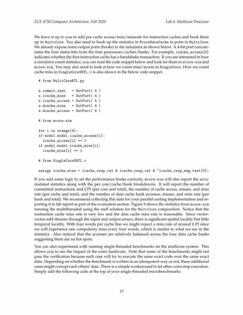
We leave it up to you to add per cache access/miss/missrate for instruction caches and hook themup in MultiCore. You also need to hook up the statistics in McoreDataCache to ports in MultiCore.We already expose some output ports (hooks) to the simulator as shown below. A 4-bit port concate-nates the four status bits from the four processors/caches/banks. For example, icache_access[0]indicates whether the first instruction cache has a handshake transaction. If you are interested in howa simulator count statistics, you can read the code snippet below and look for them in score-sim andmcore-sim. You may also need to look at how we count miss/access in SingleCore. How we countcache miss in SingleCoreVRTL.v is also shown in the below code snippet.
# from MultiCoreRTL.py
s.commit_inst = OutPort( 4 )s.icache_miss = OutPort( 4 )s.icache_access = OutPort( 4 )s.dcache_miss = OutPort( 4 )s.dcache_access = OutPort( 4 )
# from mcore-sim
for i in xrange(4):if model.model.icache_access[i]:
icache_access[i] += 1if model.model.icache_miss[i]:
icache_miss[i] += 1
# from SingleCoreVRTL.v
assign icache_miss = icache_resp_val & icache_resp_val & ~icache_resp_msg.test[0];
If you add some logic to set the performance hooks correctly, mcore-sim will also report the accu-mulated statistics along with the per core/cache/bank breakdowns. It will report the number ofcommitted instructions and CPI (per core and total), the number of cache access, misses, and missrate (per cache and total), and the number of data cache bank accesses, misses, and miss rate (perbank and total). We recommend collecting this data for your parallel sorting implementation and re-porting it in lab report as part of the evaluation section. Figure 9 shows the statistics from mcore-simrunning the multithreaded using the staff solution for the MultiCore composition. Notice that theinstruction cache miss rate is very low and the data cache miss rate is reasonable. Since vector-vector-add streams through the input and output arrays, there is significant spatial locality but littletemporal locality. With four words per cache line we might expect a miss rate of around 0.25 sincewe will experience one compulsory miss every four words, which is similar to what we see in thestatistics. Also noticed that the accesses are relatively balanced across the four data cache bankssuggesting there are no hot spots.
You can also experiment with running single-threaded benchmarks on the multicore system. Thisallows you to see the impact of the extra hardware. Note that some of the benchmarks might notpass the verification because each core will try to execute the same exact code over the same exactdata. Depending on whether the benchmark is written in an idempotent way or not, these additionalcores might corrupt each others’ data. There is a simple workaround to let other cores stop execution.Simply add the following code at the top of your single-threaded microbenchmarks.
17

ECE 4750 Computer Architecture, Fall 2020 Lab 4: Multicore Processor
num_cycles = 2260 icache0_miss = 26total_committed_inst = 1492 icache0_access = 379total_cpi = 1.51 icache0_miss_rate = 0.0686
icache1_miss = 9total_icache_miss = 55 icache1_access = 424total_icache_access = 1646 icache1_miss_rate = 0.0212total_icache_miss_rate = 0.0334 icache2_miss = 10
icache2_access = 424total_dcache_miss = 89 icache2_miss_rate = 0.0236total_dcache_access = 408 icache3_miss = 10total_dcache_miss_rate = 0.2181 icache3_access = 419
icache3_miss_rate = 0.0239core0_committed_inst = 341core0_cpi = 6.63 dcache_bank0_miss = 23core1_committed_inst = 385 dcache_bank0_access = 125core1_cpi = 5.87 dcache_bank0_miss_rate = 0.1840core2_committed_inst = 385 dcache_bank1_miss = 22core2_cpi = 5.87 dcache_bank1_access = 96core3_committed_inst = 381 dcache_bank1_miss_rate = 0.2292core3_cpi = 5.93 dcache_bank2_miss = 21
dcache_bank2_access = 85dcache_bank2_miss_rate = 0.2471dcache_bank3_miss = 23dcache_bank3_access = 102dcache_bank3_miss_rate = 0.2255
Figure 9: Reference mcore-sim Statistics for Multithreaded vvadd
int main( int argc, char* argv[] ){
if (bthread_get_core_id() != 0) return 0;...
In your lab report, discuss how each benchmark performed in each configuration. Did all of thebenchmarks perform better on the multicore? Did they get the theoretical speedup of 4X over thesingle core? If you ran single-threaded benchmarks on the multicore system, is it slower than runningon the single-core system? What is the slowdown due to? How do the two versions of sortingimplementations perform on these two architectures? Can the parallel sort get a speedup over theserial version of sorting? Dive deeper into the result and discuss why you get the specific speedup.
6. Extensions
Advanced students might want to consider modifying the software and/or hardware to improvethe performance of their parallel sorting microbenchmark. A small bonus will be given to the fastestfew designs. We will run your sorting microbenchmark on your multicore system using one or moreof our own private datasets. These datasets will be similar in size to the dataset we give you, butmay not necessarily have exactly 128 elements. You can assume the data in these datasets will beuniformly distributed 32-bit random integers. Note that students should only attempt improvingthe software and/or hardware once everything is completely working and they have finished a draftof the lab report. The rest of this section includes some ideas on how you might want to improveyour design.
18

ECE 4750 Computer Architecture, Fall 2020 Lab 4: Multicore Processor
You will definitely want to experiment with the network. You will want to think critically aboutwhether or not a bus or a ring makes the most sense for CacheNet or MemNet, and then run someexperiments to see which achieves the best performance for a certain network composition. Someextra performance hooks may help you understand the injection rate/latency in a realistic multicoresystem context. You might also want to use bus for some networks and and ring for other networksto get better performance. You will also want to experiment with different parallel sorting algorithmsas algorithmic changes can often have the largest impact.
When you evaluate your SingleCore, you will quickly find that the performance of your baselineand even alternative multicore system is limited by the hit latency of the cache you designed in Lab3. While we could move to a more aggressive pipelined cache microarchitecture, you can achievemuch of the same benefit by simply merging states in the FSM control unit used in this lab. Ideally,you would merge enough states to enable a single-cycle hit latency for reads (i.e., a single statefor read hits) and a sustained throughput of one read hit per cycle. This requires performing tagcheck and data access in parallel, and carefully handling the val/rdy signals for the cache requestand response interfaces. Writes can potentially use two states to do tag check and data access insequence, although single-cycle hit latency for writes is still possible if the cache response is sentback in the first state. Reducing the read hit latency is the most critical since this would improve theperformance of instruction fetch in your processor.
After you finish the cache hit latency, you might also notice that you are wasting some cycles dueto control hazards. Our sorting microbenchmark will have one or more loops, and the pipelinedprocessor designed in this lab will almost always mispredict the backwards branch used in theseloops. Adding a simple branch target buffer (BTB) in the F stage could improve the performanceof the provided microbenchmarks, and the sorting implementation, by effectively eliminating mostsquashes due to the backwards branch used in loops. A simple, yet effective approach would be toinclude a four entry BTB in the F stage. Each entry would include a valid bit, the PC of the branch,and the target address for the branch when it is taken. In the F stage, your processor would need tosearch the BTB for the current PC. If there is a hit, then the F stage can use the corresponding targetaddress in the BTB. If there is a miss, then the F stage can simply use PC+4. If a branch is taken, thenin the X stage we would need to write the BTB with the corresponding PC of the branch and targetaddress. More complicated schemes are certainly possible.
Acknowledgments
This lab was created by Shunning Jiang, Shuang Chen, Ian Thompson, Megan Leszczynski, GaurabBhattacharya, Moyang Wang, Christopher Torng, Berkin Ilbeyi, Christopher Batten, and Ji Kim aspart of the course ECE 4750 Computer Architecture at Cornell University.
19