ece 340 lecture 4 : bonding forces and energy...
TRANSCRIPT

ECE 340Lecture 4 : Bonding Forces
and Energy Bands
Class Outline:
Crystal Diffraction•Crystal Bonding•Energy Band Formation
M. J. Gilbert ECE 340 – Lecture 4 8/29/1 1
Things you should know when you leave…
Key Questions• Why is the Bohr model useful?• What is the Schrödinger equation?• What is a wavefunction?• What are the most common
chemical bonds?• What are energy bands?• What is an energy gap?

M. J. Gilbert ECE 340 – Lecture 4 8/29/1 1
Crystal Diffraction
• Crystal structure is determined in experiment by studying the diffraction of suitable wave sources from particular sets of crystal planes.
• X-ray diffraction is most widely exploited in practice and arises from the interaction of the incoming wave with the electron cloud of each atom in the crystal.
Last time, we discussed crystal lattices and structure. How can we determine this?
•SCHEMATIC ILLUSTRATION OF X-RAY DIFFRACTION BY AN ATOM IN A CRYSTAL.
• THE ELECTRIC FIELD ASSOCIATED WITH THE INCOMING X-RAY ACCELERATES THE CLOUD OF ELECTRONS THAT SURROUND THE ATOM.
• THE ACCELERATED ELECTRONS THEN EMIT SO-CALLED SECONDARY X-RAYS WITH THE SAME PHASE AND WAVELENGTH AS THE INCIDENT RADIATION.
• WE MAY THEREFORE CONSIDER EACH ATOM IN THE CRYSTAL TO BE A SOURCE OF SECONDARY WAVES.
• THE STRENGTH OF THE SECONDARY X-RAYS IS DETERMINED BY THE SCATTERING POWER OF THE ATOM WHICH QUANTITY IS KNOWN AS THE ATOMIC FORM FACTOR.
M. J. Gilbert ECE 340 – Lecture 4 8/29/1 1
Crystal Diffraction
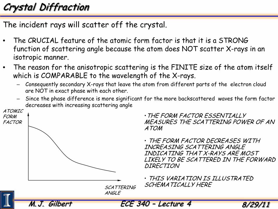
• The CRUCIAL feature of the atomic form factor is that it is a STRONG function of scattering angle because the atom does NOT scatter X-rays in an isotropic manner.
• The reason for the anisotropic scattering is the FINITE size of the atom itself which is COMPARABLE to the wavelength of the X-rays.
– Consequently secondary X-rays that leave the atom from different parts of the electron cloud are NOT in exact phase with each other.
– Since the phase difference is more significant for the more backscattered waves the form factor decreases with increasing scattering angle
The incident rays will scatter off the crystal.
ATOMICFORMFACTOR
SCATTERINGANGLE
•THE FORM FACTOR ESSENTIALLY MEASURES THE SCATTERING POWER OF AN ATOM
• THE FORM FACTOR DECREASES WITH INCREASING SCATTERING ANGLE INDICATING THAT X-RAYS ARE MOST LIKELY TO BE SCATTERED IN THE FORWARDDIRECTION
• THIS VARIATION IS ILLUSTRATED SCHEMATICALLY HERE

M. J. Gilbert ECE 340 – Lecture 4 8/29/1 1
Crystal Diffraction
• Each plane causes a reflection of a small portion of the incident rays.– This number is usually a few percent of the total incident beam.
• Waves in successive planes interfere with one another– This process is critical for the observation of crystal diffraction.
Now consider an incident beam of x-rays…
•SCHEMATIC IMAGE ILLUSTRATING THE REFLECTION OF AN INCOMING X-RAY BEAM FROM A PARTICULAR SET OF CRYSTAL PLANES
• BECAUSE OF THE STRONG ANGULAR DEPENDENCE OF THE ATOMIC FORM FACTOR WE MAY CONSIDER THAT ONLY A SMALLFRACTION OF THE INCOMING WAVE IS REFLECTED BY ANY GIVEN PLANE

M. J. Gilbert ECE 340 – Lecture 4 8/29/1 1
Crystal Diffraction
• For reflection from a set of crystal planes with spacing d and with incident illumination of wavelength.
• There is a special set of angles for which the interference is constructive and so for which strong reflection of the X-ray beam occurs.
• This set of angles is given by the Bragg condition which is obtained by considering the interference of waves reflected from two successive planes.
Typically, rays incident from an arbitrary angle interfere destructively
θ θ
d θθdsinθ dsinθ
I
II
• By the time the two waves leave the crystal wave-II has traveled a distance 2dsinΘ LONGER than wave-I
* A PHASE-DIFFERENCE therefore exists between the two waves which may be written as
* When this phase-difference is equal to an INTEGER the waves interfere constructively and this leads to the BRAGG CONDITION
λθ /)sin2( d
,3,2,1,sin2 == nnd λθ

M. J. Gilbert ECE 340 – Lecture 4 8/29/1 1
Crystal Diffraction
• In the figure below, we show the measured variation of the reflected X-ray intensity at an incident angle for a crystalline sample of silicon carbide (SiC)
• A major peak is observed at 2Θ = 36° at an incident wavelength of 1.9 Ǻ corresponding to an interplane spacing of 3.2 Ǻ.
• This agrees with the known lattice spacing of silicon (111).
How is it done experimentally?X-RAY
SOURCE
CRYSTAL
DETECTOR
PATH OFDETECTOR
Y. Sun et al.J. Appl. Phys. 82, 2334 (1997)
(111) PLANE IN SILICON
M. J. Gilbert ECE 340 – Lecture 4 8/29/1 1
Crystal Bonding
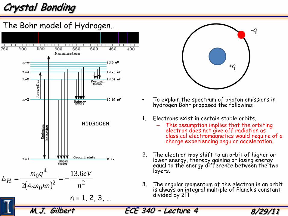
• To explain the spectrum of photon emissions in hydrogen Bohr proposed the following:
1. Electrons exist in certain stable orbits.– This assumption implies that the orbiting
electron does not give off radiation as classical electromagnetics would require of a charge experiencing angular acceleration.
2. The electron may shift to an orbit of higher or lower energy, thereby gaining or losing energy equal to the energy difference between the two layers.
3. The angular momentum of the electron in an orbit is always an integral multiple of Planck’s constant divided by 2Π
The Bohr model of Hydrogen…
+q
-q
( ) 220
40 6.13
42 neV
nqmEH −==πε
n = 1, 2, 3, …
M. J. Gilbert ECE 340 – Lecture 4 8/29/1 1
Crystal Bonding
• The Bohr model explains some things but is inadequate to explain many other observable phenomena.
• Use wave mechanics – Schrödinger equation
• Based on three essential postulates:1. Each particle in the system is defined by a wavefunction. The wavefunction and its
space derivative are continuous, finite and single valued.
2. We must express the normal classical quantities with the new quantum mechanical formulations.
3. The probability of finding a particle with a given wavefunction within a volume should be unity.
The Schrödinger Equation:

M. J. Gilbert ECE 340 – Lecture 4 8/29/1 1
Crystal BondingUsing the Schrödinger Equation: Free electron gas
V = 0
0 L
0L
),,(),,( zyLxzyx +=ψψ
),,(),,( Lzyxzyx +=ψψ
),,(),,( zLyxzyx +=ψψ
kx
ky
kz
-3 -2 -1 1 2 30nx,y,z =
( ) ( )xikx x ⋅= expψ
;...4;2;0LL
kxππ
±±=
The solution wavefunctions:
Momentum space becomes discretized…

M. J. Gilbert ECE 340 – Lecture 4 8/29/1 1
Crystal BondingIonic Bonding: NaCl
Sodium (Na)+ Chlorine (Cl)-
a
y
z
x

M. J. Gilbert ECE 340 – Lecture 4 8/29/1 1
Crystal Bonding
• Outer shell is only partially filled• Screening by other charges makes the valence electron very
loosely bound.• Outer electron contributed to crystal as a whole.• Bonding can be very complex depending on the compound
involved.
Metallic Bonding : Sodium (Na)
e- e- e- e-

M. J. Gilbert ECE 340 – Lecture 4 8/29/1 1
Crystal Bonding
• Look to the simplest materials – Hydrogen– By assuming that only one electron is present, we can neglect the interaction
of electrons in the molecule.– We can still understand the critical features.
• Consider the case of two atoms A and B with ground state wavefunctions shown below:– The resulting molecule is a superposition of the two atomic wavefunctions
The most important type of bonding : Covalent
+ +
-
BA ψψψ ±=±
A BA
B r
rr
Aψ
Bψ
+ψ
BA r
*++ψψ
SymmetricState

M. J. Gilbert ECE 340 – Lecture 4 8/29/1 1
Crystal Bonding
• The antisymmetric wavefunction gives a reduced probability of finding the electron between the two atoms.– The solution to the Schrödinger equation shows that the symmetric
state lies lower in energy.– The symmetric state is referred to as the bonding state and the
antisymmetric state is referred to as the anti-bonding state.
But another combination of wavefunctions exists.
*−−ψψ
A
B r
r
Aψ
Bψ
BA r
−ψ
BA r

M. J. Gilbert ECE 340 – Lecture 4 8/29/1 1
Crystal Bonding
• The variation of the total energy of the hydrogen molecule as a function of inter-atomic separation is shown for the bonding and anti-bonding states.
• There is no minimum present in the anti-bonding state indicating the absence of a stable molecular state.
• In the bonding state there is a minimum which defines a stable molecular state at a certain inter-atomic separation.
• When this occurs there is an enhanced probability of finding the electron between the two atoms.
Visualizing the bonding vs. anti-bonding states
INTER- ATOMICSEPARATION
E
E+
E-
• WITH THE ATOMS FAR APART FROM EACH OTHER THE BONDING AND ANTI-BONDING STATES ARE EQUAL IN ENERGY.
• AT SUCH LARGE SEPARATIONS THE TOTAL ENERGY OF THE TWO ATOMS IS EQUAL TO THAT OF A PAIR OF INDEPENDENT HYDROGEN ATOMS.
• AS THE INTER-ATOMIC SEPARATION IS REDUCED HOWEVER THE ENERGY OF THE BONDING STATE DECREASES FASTER THAN THAT OF THE ANTI-BONDING STATE.
• THE EXISTENCE OF A MINIMUM ENERGY IN THE BONDING STATE DETERMINES THE EQUILIBRIUM SEPARATION OF THE HYDROGEN ATOMS IN THE MOLECULE .

M. J. Gilbert ECE 340 – Lecture 4 8/29/1 1
Crystal Bonding
• Each atom shares bonds with 4 other atoms.
• Silicon bonds are covalent, but compound semiconductors have a mix of ionic and covalent bonds.– Depends on separation on periodic table.
Now we can examine elemental and compound semiconductors.
1s 2s 2px 2py 2pz 3s 3px 3py 3pz
s-ORBITAL p-ORBITAL sp3-ORBITAL
DIAMOND CRYSTAL STRUCTURE WITH TETRAHEDRAL BONDING … EXAMPLES
INCLUDE SILICON & GERMANIUM
When silicon atoms COMBINE to form a crystal the s- and p- orbitals HYBRIDIZE to form so-called sp3 ORBITALS that are mixtures of the s- and p-orbitals.

M. J. Gilbert ECE 340 – Lecture 4 8/29/1 1
Energy Band FormationBring atoms together, the wavefunctions begin to overlap.
Large Separation
Small Separation

M. J. Gilbert ECE 340 – Lecture 4 8/29/1 1
Energy Band Formation+
IN A SINGLE ATOM ELECTRONS ARETRAPPED IN A POTENTIAL WELL
+ + + +
WHEN MANY ATOMS COMBINE AND FORM A CRYSTAL THE ATOMICPOTENTIALS OVERLAP GIVING RISE TO A PERIODIC VARIATION
POTE
NTI
AL

M. J. Gilbert ECE 340 – Lecture 4 8/29/1 1
Energy BandsWe conclude by looking at the free electron model…
( )2222
2 zyxk kkkm
E ++=
Allowed energy values:
kx
-3 -2 -1 1 2 30nx,y,z =
So, let’s look at a 1D crystal with periodic boundary conditions:
),,(),,( zyLxzyx +=ψψ
Wavefunction solutions are in the form of travelling waves: ( ) ( )xikx x ⋅= expψ
Solutions to the Schrödinger equation discretize the allowed values: ;...4;2;0
LLkx
ππ±±=
a

M. J. Gilbert ECE 340 – Lecture 4 8/29/1 1
Energy BandsIf the wavevectors at kx = ± Π/a, satisfy the Bragg condition
θ θ
d θθdsinθ dsinθ
I
II
,3,2,1,sin2 == nnd λθBragg Condition:
Then the resultant wave is a combination of left and right going waves (Standing wave):
( )
( )
→
−−
=−
→
−+
=+
axi
axi
axi
ax
axi
axi
πππψ
πππψ
sin2expexp
cos2expexp
( ) ( )
( ) ( )
∝−=+
∝+=+
axax
πψρ
πψρ
22
22
sin
cos
Examine the density:

M. J. Gilbert ECE 340 – Lecture 4 8/29/1 1
Energy BandsTo find the energy gap, we look at the energies:
Let’s assume that the potential in our crystal can be written as:+ + + +
( )
=
axUxU π2cos
The energy gap is the energy difference between these two standing waves:
( ) ( ) ( )[ ]
Uax
ax
axdxU
xdxUEg
=
−
=
−−+=
∫
∫1
0
22
1
0
22
sincos2cos2 πππ
ψψ

M. J. Gilbert ECE 340 – Lecture 4 8/29/1 1
Energy BandsBy putting the atoms together, we get an energy gap
• The top band is referred to as the “conduction” band.– At low temperatures it is mostly empty of electrons.
• The bottom band is referred to as the “valence” band.– At low temperatures it is almost entirely filled with
electrons.
Eg
Energy
Ec
Ev
Distance (x)