ece 120 final exam fall 2016 -...
TRANSCRIPT

ECE 120 Final Exam Fall 2016
Wednesday, December 14, 2016
Name: NetID: ____________________________________ _______________ Discussion Section: 9:00 AM 10:00 AM 11:00 AM [ ] AB1 [ ] AB8 12:00 PM [ ] AB2 [ ] AB9 1:00 PM [ ] AB3 [ ] ABA 2:00 PM [ ] AB4 [ ] ABB 3:00 PM [ ] AB5 4:00 PM [ ] AB6 [ ] ABC 5:00 PM [ ] AB7 [ ] ABD
Be sure that your exam booklet has 14 pages. Write your name, netid and check discussion section on the title page. Do not tear the exam booklet apart, except for the last four pages. Use backs of pages for scratch work if needed. This is a closed book exam. You may not use a calculator. You are allowed two handwritten 8.5 x 11" sheets of notes (both sides). Absolutely no interaction between students is allowed. Clearly indicate any assumptions that you make. The questions are not weighted equally. Budget your time accordingly.
Problem 1 20 points ___________
Problem 2 16 points ___________
Problem 3 14 points ___________
Problem 4 21 points ___________
Problem 5 14 points ___________
Problem 6 8 points ___________
Problem 7 7 points ___________
Total 100 points ___________

2
Problem 1 (20 points): Binary Representation and Operations, Hamming codes
1. (2 points) There are 365 days in a year. If we want to uniquely identify each day using
2’s complement binary representation, what is the minimum number of bits we should use?
Minimum number of bits: _______________ (decimal number) 2. (4 points) Convert the following 24-bit pattern to hexadecimal:
1100 0000 1111 1111 1110 11102 = x_______________ (hexadecimal number) 3. (4 points) Perform the following bitwise logical operations.
a) 0110 NAND 0011 = ________________
b) 1001 XOR ( NOT(0101) ) = _______________
4. (4 points) Perform the following operation in four-bit 2’s complement representation.
0101 + 101 = Circle one: Carry out? YES NO Circle one: Overflow? YES NO
5. (6 points) Someone just sent you the following 7-bit Hamming code: X7X6X5X4X3X2X1 = 1010111. Does the message have an error or not?
Circle one: YES NO
If you think there is an error, write the position where there is an error:
There is an error in position

3
Problem 2 (16 points): LC-3 Assembly Programming
Greetings, ECE 120 student. Your mission, should you choose to accept it, is to write the missing lines of code, so the program can properly print on screen a message to wish you an enjoyable break. Additionally, you must write the missing entries in the symbol table associated with this program. As always, should you or any of your friends be caught or killed, the ECE 120 instructors will disavow any knowledge of your actions. This page will self-destruct by the end of the semester. Good luck, ECE 120 student. 1. (11 points) Write the missing lines of code. You must write one instruction per missing
line. .ORIG x6000
; Print "Choose message: "
;
LD R1, OPTION ; R1 <- M[OPTION]
; Read from keyboard
NOT R0, R0 ; R0 <- R1-R0
;
ADD R0, R1, R0 ;
; Character typed = R1?
; Case: character typed = R1
EQUAL LEA R0, HOLIDAYS ; R0 <- HOLIDAYS
BRnzp PRINTOUT ; Go to PRINTOUT
; Case: character typed ≠ R1
DIFFERENT LEA R0, NEWYEAR ; R0 <- NEWYEAR
PRINTOUT PUTS ; Print selected message
;
PROMPT .STRINGZ "Choose message: "
OPTION .FILL x0031 ; ASCII '1'
HOLIDAYS .STRINGZ "Happy Holidays!"
NEWYEAR .STRINGZ "Happy New Year!"
.END

4
Problem 2 (16 points): LC-3 Assembly Programming, continued
2. (5 points) Write the missing entries in the symbol table. Answers in hexadecimal only. // Symbol table
// Scope level 0:
// Symbol Name Page Address
// ---------------- ------------
// EQUAL
// DIFFERENT 600A
// PRINTOUT 600B
// PROMPT 600D
// OPTION
// HOLIDAYS 601F
// NEWYEAR

5
Problem 3 (14 points): Synchronous Counter
1. (11 points) Using D flip-flops, design a 3-bit counter that counts the prime number
sequence 2, 3, 5, 7, and repeats. The current state of the counter is denoted by S2S1S0. Fill in the K-maps for S2
+, S1+ and S0
+ using don’t cares wherever possible. S2
+ S1S0 00 01 11 10
S2 0
1
S1+ S1S0
00 01 11 10
S2
0
1
S0+ S1S0
00 01 11 10
S2
0
1
Write minimal SOP Boolean expressions for S2+, S1
+, and S0+.
S2+ =
S1+ =
S0+ =
2. (3 points) Suppose you have already designed a 2-bit binary up-counter that counts in the
sequence 0, 1, 2, 3, and repeats. You could attach output logic so that the 2-bit state of this counter produces a 3-bit output: the repeating prime number sequence 2, 3, 5, 7. Write down one advantage of the approach described here compared to the implementation in part 1. Express your answer in 10 words or fewer. (We will not read more than 10 words.)
___________________________________________________________________
6
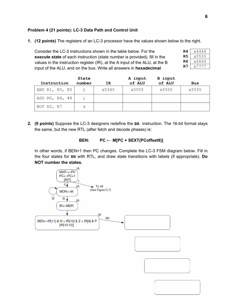
Problem 4 (21 points): LC-3 Data Path and Control Unit
1. (12 points) The registers of an LC-3 processor have the values shown below to the right.
Consider the LC-3 instructions shown in the table below. For the execute state of each instruction (state number is provided), fill in the values in the instruction register (IR), at the A input of the ALU, at the B input of the ALU, and on the bus. Write all answers in hexadecimal.
Instruction State number IR
A input of ALU
B input of ALU Bus
AND R1, R5, R5 5 x5345 x5555 x5555 x5555
ADD R0, R4, #8 1
NOT R2, R7 9
2. (9 points) Suppose the LC-3 designers redefine the BR instruction. The 16-bit format stays
the same, but the new RTL (after fetch and decode phases) is:
BEN: PC ← M[PC + SEXT(PCoffset9)]
In other words, if BEN=1 then PC changes. Complete the LC-3 FSM diagram below. Fill in the four states for BR with RTL, and draw state transitions with labels (if appropriate). Do
NOT number the states.
R4 x4444 R5 x5555 R6 x6666 R7 x7777

7
Problem 5 (14 points): FSM Analysis The FSM on the left below performs a serial calculation on an input A. Four bits are provided through A each cycle. In the first cycle, the F input (“first bits”) is set to 1. In all subsequent cycles, F=0. After N cycles, the value S provides the answer as an unsigned number. The size of the FSM depends on the parameter k, which must be at least 3. Notice that the FSM makes use of a register to hold the state (S is just the stored register value), a set of k 2-to-1 muxes controlled by F, and a k-bit adder. The mystery box (implementation shown on the right below) transforms A into a 3-bit value B, which is then treated as an unsigned number and zero-extended (padded with leading 0s) to k bits.
The questions you need to answer are in the following page.
Tear the last page and use it as scratch paper.

8
Problem 5 (14 points): FSM Analysis, continued Answer the questions below based on the FSM design and description on the previous page. In order to help you solving these questions, we strongly suggest that you fill in the truth table for the mystery box. To do that, feel free to tear apart the last page of the exam and use it as scratch paper, because we will NOT grade the truth table. Circle EXACTLY ONE ANSWER for each question. 1. (3 points) What is the smallest possible value represented by the unsigned bit pattern B,
given the implementation of the mystery box?
a) -4 b) 4 c) 1 d) -3 e) 0
2. (3 points) What is the largest possible value represented by the unsigned bit pattern B, given the implementation of the mystery box?
a) 7 b) 0 c) 3 d) 4 e) -4
3. (4 points) The V output from the adder signifies overflow in the stored value. In terms of k, what is the minimum number of cycles (including the F=1 cycle) for which the FSM can execute before V=1?
a) 1 b) 2k-2 - 1 c) 2k-1 - 1 d) 1 - 2k e) ceil (2k / 7) – 1
4. (4 points) What is the meaning of the output S?
a) S is the number of cycles in which input A has an odd number of 1 bits.
b) S is the number of 1 bits passed in through A.
c) S is the sum of 2’s complement values passed in through A.
d) S is the number of 0 bits passed in through A.
e) None of the above.

9
Problem 6 (8 points): LC-3 Instructions and Assembler
1. (5 points) Decode each of the following LC-3 instructions, writing the RTL in the box beside
the instruction. For full credit, your RTL must include specific values for each operand (for example, “R4” rather than “DR”), and must be sign-extended when appropriate. Do not perform calculations such as addition of the PC value.
You may write any immediate values either as hexadecimal (prefix them with “x”) or as decimal (prefix them with “#”).
Hint: Draw lines between bits to separate the instructions into appropriate fields.
Instruction bits RTL Meaning
0001 1110 1011 0010 R7 ← R2 - #14, setcc 1100 0001 0100 0000
1011 0010 0101 0011
0110 0010 1000 0011 2. (3 points) The LC-3 assembler finds a single error in the following code. State the nature
of the error and in which pass the assembler identifies the error (first or second).
.ORIG x3000 LEA R1,STRING PRINT LDR R0,R1,#0 BRz DONE TRAP x21 ; OUT ADD R1,R1,#1 BRnzp PRINT DONE LEA R1,STRING AGAIN LDR R0,R1,#0 BRz DONE TRAP x21 ; OUT ADD R1,R1,#1 BRnzp AGAIN DONE HALT STRING .STRINGZ "This is my string." DATA .FILL xFFFF .END
Circle one: PASS 1 PASS 2 Nature of error: Express your answer in 10 words or fewer. (We will not read more than 10 words.)

10
Problem 7 (7 points): LC-3 Assembly Language Interpretation All questions for this problem pertain to the following code. .ORIG x3000 LDI R1,MAGIC AND R3,R3,#0 OUTER AND R2,R2,#0 ; outer loop starts here AND R0,R0,#0 INNER ADD R0,R0,R0 ; inner loop starts here ADD R1,R1,#0 ; the inner loop left shifts bits R1[15:12] BRzp ZEROBIT ; out of R1 and into R0[3:0] to form ADD R0,R0,#1 ; a single hex digit ZEROBIT ADD R1,R1,R1 ADD R2,R2,#1 ADD R4,R2,#-4 BRn INNER ; end of inner loop ADD R4,R0,#-10 ; start of 'curious code' BRzp FORWARD LD R2,DIGIT0 ADD R0,R0,R2 BRnzp LABEL FORWARD LD R2,LETTERA ADD R0,R4,R2 LABEL OUT ; end of 'curious code' ADD R3,R3,#1 ADD R4,R3,#-4 BRn OUTER ; end of outer loop LD R0,NEWLN OUT HALT MAGIC .FILL x4000 DIGIT0 .FILL x30 ; ASCII digit 0 ('0') LETTERA .FILL x41 ; ASCII letter A ('A') NEWLN .FILL x0A ; ASCII newline character ('\n') .END 1. (1 point) How many times does the body of the outer loop execute? 2. (1 point) How many times does the body of the inner loop
execute (for each outer loop iteration)? 3. (3 points) What does the 'curious code' marked in the comments do? Express your
answer in 10 words or fewer. (We will not read more than 10 words.)
4. (2 points) Explain how to make the program print “ECEB” followed by a newline character to
the LC-3 display. Express your answer in 10 words or fewer. (We will not read more than 10 words.)

LC-3 TRAP Service Routines
LC-3 Control Word Fields
LC-3 Microsequencer Control

LC-3 Instructions
LC-3 FSM

LC-3 Datapath
LC-3 Datapath Control Signals

Problem 5’s help page (use as scratch copy, we will NOT grade it)
A3 A2 A1 A0 B2 B1 B0
0 0 0 0
0 0 0 1
0 0 1 0
0 0 1 1
0 1 0 0
0 1 0 1
0 1 1 0
0 1 1 1
1 0 0 0
1 0 0 1
1 0 1 0
1 0 1 1
1 1 0 0
1 1 0 1
1 1 1 0
1 1 1 1
REPLICATED FROM PROBLEM STATEMENT FOR YOUR CONVENIENCE: The FSM on the left performs a serial calculation on an input A. Four bits are provided through A each cycle. In the first cycle, the F input (“first bits”) is set to 1. In all subsequent cycles, F=0. After N cycles, the value S provides the answer as an unsigned number. The size of the FSM depends on the parameter k, which must be at least 3. Notice that the FSM makes use of a register to hold the state (S is just the stored register value), a set of k 2-to-1 muxes controlled by F, and a k-bit adder. The mystery box (implementation shown above on the left) transforms A into a 3-bit value B, which is then treated as an unsigned number and zero-extended (padded with leading 0s) to k bits.