eccm16 seville, june 2014 most innovative cfrp … · 5 3.3.- sizing stress & fem approach on...
TRANSCRIPT

1
ECCM16 – SEVILLE, June 2014 MOST INNOVATIVE CFRP SOLUTIONS FOR A350XWB RFE S19 AIRFRAME:
CO-CURED SHELL & INTEGRATED RTM DOOR-FRAME
Airbus AOSL Getafe J. Sanchez, R. Avila, J.C. Gomez, D Cerezo, F Muñoz, F. Escobar J M Blanco. M Huertas
Abstract
A350XWB S19 features brand-new full-barrel-360º integrated co-cured shell (6.mx5.m) & integrated co-injected RTM-door-frame (3.m); both including end-to-end Concurring approach/Development in: Raw-Materials, Design & Stress, Manuf. Process and industrial solutions for high production rates. Both Barrel & RTM-Frame are the summit of a dedicated development plan, and concerned R&D projects (+Airbus experience on ATL/AFP panels and advanced RTM designs for SA, LR & A380 as well). Concerning M&P, brand-new prepreg material has been developed in the frame a collaborative programme (ACI: Airbus Composite Initiative). ACI specific project was carried out with Hexcel to develop new intermediate modulus (IM) carbon fiber/resin system featuring improved mechanical properties as well as manufacturing characteristics. On parts Design: full-concurrent approach, DMU-Integration & PDM-Management was set on top of key Design aspects as: New/enhanced Design/Stress principles, customized Methods as ply-by-ply and 3D Cad/Cam tools, optimized light-weight lightning strike protection, integrated non-linear (NL) Stress analysis & Testing and Certification approach to large CFRP parts compatible with minimum weight design. Airframe Certification is based upon full-integrated Test-Plan (Static & F+DT), as well as Stress/Design methods validation and derivation of design allowable values. Building-block “Test Pyramidt” approach includes: Generic tests for data used in design (M&P, NSDW & SDW), components tests to validate design (panels, Elements) & Full-Scale Static & F+DT tests. It must be noted that S19 Design poses significant certification challenges due to the use of brand-new material and processes but, on top, to its hybrid structure Alu/CFRP(+Ti). Last but not least, this paper includes the key aspects on Manufacturing Process & Industrial systems as: Advanced AFP process for 360º skin, Curing Tool design for full-mandrel & dedicated Industrial systems (demoulding, trimming/drilling, NDT, etc.) & fully customized RTM cell.
1.- Introduction
Fuselage S19 Airframe design is made of following main structural elements:
360º Cfrp shell with co-cured Skin/Stringers
Frames & Frame joints (Al & CFRP)
CFRP Access Door-Frame
CFRP HTP-Cut-Out Beams
FR102/HTP-rear Integration
THSA-fitting/HTP-fwd attachement
Fig 1: S19 Airframe & Internal Struct.

2
On Composite technologies field this paper focuses on the brand-new one-shot 360º-full-barrel (6+ m Long) with hat-section co-cured stringers, designed for mid-grade AFP/ATL prepreg, & large-integrated co-injected access RTM-door-frame (3 m long).
Fig 2 : S19 Cfrp Shell & Door-Frame Full-Barrel co-cured panel design is last step of the Airbus experience in CFRP design and development programs coming from A380 RFE as reference with 6 panels in S19 and 2 halves shells in S19.1 to A350-S19 featuring a single-piece full barrel.
Fig3: Fuse Shells techno evo to A350-S19 full-Barrel
Fig 4: A350 Full-Barrel development Parts Similar development steps have been taken in RTM parts development to arrive to the fully integrated door-frame featured in A350 S19. From limited size injected parts to an integral co-injected part involving large scale RTM tooling (3x3 sqm tooling for 2,6x2,6 sqm part).
Fig 5: RTM techno evo to A350-S19 Large Integrated Frame
2. Materials and Manufacturing
processes
2.1 Material Selection Composite material used for manufacturing of Section 19 skins has been developed in collaboration with Hexcel Composites inside the framework of a collaboration project with Hexcel. called Airbus Composite Initiative project (ACI). Inside ACI, Airbus collaborate with main composite suppliers in order to develop leading materials in term of mechanical, electrical and manufacturing properties and characteristics.

3
Specifically in the collaboration chapter with Hexcel Composites, a prepreg material with denomination M21E/IMA has been developed and adapted to Airbus needs with different grades and presentations. This material is an interleaved 180ºC curing , epoxy resin with Intermediate modulus carbon fiber. Specifically for section 19 a FP and ATL grades have been developed and qualified using Airbus AIMS specifications. M21E/IMA material presents superior characteristics in term of material allowables as well as manufacturing performance. A complete range of additional materials has been qualified to assure full compatibility with main prepreg, as well as auxiliary materials used for tooling or vacuum bagging. Textiles and infusion materials already qualified and in use in A380 have been further exploited in A350 Section 19. Similar CFRP RTM frames are manufactured, although under more severe forming constraints imposed by A350 tailcone geometry. The most significant challenge has been the development of the integrated THSA door frame, a large component that integrates longerons, lintels and frames in a single RTM component. Specific preforming, curing and post-cure cycles have been qualified to guarantee material and component performance while satisfying all processing constraints. A novel and systematic First Part Qualification approach has been implemented for the first time at overall airframe level. This approach has led to the benchmarking and full characterization of the internal quality of first production elements, setting the basis for industrial quality standards. This has allowed identifying at early stages specific features that might require detailed analysis or justifications based on Airbus Effect of Defect policy as well as triggering manufacturing improvements during early phases of development
2.2- Manufacturing flow diagram The full barrel manufacturing process consists of the following operations:
Fig 6 : Manufacturing diagram
RTM techno in Getafe Plant has been improved quite a lot since the introduction of the technology for the A380, therefore for A350, the technology was ready to go 1 step forward: the integration of 8 former structural parts (6 beams sectors+2 frame sectors) plus all the join parts between them, clips, bavettes...(for a total of 38 parts integrated in just 1!) was deemed to be feasible, and of course without risk ing the tolerances required.
Fig7: Previous 38 parts Door Frame structure (A380) The fact of delivering all those former parts in 1 single part would save a lot of time in assembly although the big challenge was to achieve it WITHIN tolerances. RTM process was improved in such way, that for A350 it has been created a new process patented under the name of HARTM (High Accuracy RTM). The process is based on the use of a double curing cycle with a partial polymerization of the resin in the first one, so as the 2nd cycle , out of the injection tooling, can be dedicated to achieve high tolerances on the interface with the fuselage, correcting possible spring backs coming from 1st cycle. More details in European Patent Number EP12382241.3

4
3.- CFRP Parts Concurrent Design Specific A350 S19 design and development approach for Composites require the early and continuous concurrent work among key actors as M&P, Stress, Design and Manufacturing (+Procurement, etc.) during the concept and definition of the component to design the optimum component for performance and production rates, for instance: - Early definition of Manufacturing Capability
Document (global A350 approach for all major components) for the Concept phase, evolved into a MCD for the definition phase to be considered into the design from the beginning.
- Intense cooperation between design and stress in the most radical and challenging concepts / features in the CFRP parts as: Skin lay-up & ply drop-offs, hat-section optimised stringers & dedicated demoulding studies, specific RTM-parts cross-nodes design
3.1.- Integrated Design Approach, Methods & Tools S19 Overall Design, including large CFRP parts is based upon a common 3D-as-Master philosophy i.e., Full-DMU-Integration & PDM management with 3D design solution (DS)/Design Data Set (DDS) used as Single reference for: Conformity between DDS and A/C Definition Integrated DDS Airbus-RSP-Customers Fully-Coupled Design & Stress tools-kit,
integrating CAD/CAE tasks (ISAMI) Manufacturing (Purchase, Production,
Install/Assy, Rigging, Tests) Quality-Checks & Inspection Justification ( Certification) Maintenance / MRO (tech publications, spares,
retrofit/repair definition)
Fig8: Design Data Set Consistency
Fig9: PDM release process & DDS Check DDC 3.2.- S19 Large CFRP parts Specific Design Specific Design Work for S19 Composite parts is a step ahead versus previous industry standards. S19 detailed design (and composite parts) is based on: Dedicated/Customized Design/Stress rules,
process, methods & tools. CFRP design principles with specific enhanced
rules for AFP complex 3D skin and Integrated RTM-Frame
Customized ply-by-ply and 3D CAD/CAM design tools
Optimized light-weight lightning strike protection. Customized Airframe surface & corrosion
protection.
Fig10: S19 Airframe: CFRP parts framed-red Most relevant CFRP design Principles linked to CFRP 360º-Barrel & RTM-frame are:
• Lay-up / stacking rules • Ramp rates customized to local main
loading/stress fields • Special Design Features as Stringers ru-
outs (SRO) & Cut-outs • CFRP thick-Beams Joints/Splices • Bolted-Joints • Thermal Analysis
S19
Skin & Stringers
CFRP Beams
Metallic Frames
Forged Frames & VTP Root Joint
THSA Fittings
FR102 & HTP Rear Attachment
CFRP Frames & Rear Corner FramesIntegral Door Frame

5
3.3.- Sizing Stress & FEM Approach On the stress / strength justification side, extensive use of advanced detailed FEM models (DFEMs) is done and, first time in Airbus, intensive use of full-scale component “Virtual-testing” based upon an advanced non-Linear model (NL ViFST). Basically all S19 FEMs are attached to GFEMs (see fig.) in order to properly consider the real boundary and loading conditions
Fig11: GFEM, iDFEM & DFEM’s Sk in Sizing Optimization process starts with Baseline sizing tools to derive RF’s mapping and identify critical areas and critical load cases, then validation / challenge and optimisation is completed with support of non-linear advanced model used as Virtual-Testing (ViFST). S19 ViFST Analysis approach ViFST S19 model is used for advanced NL analyses. Modelling criteria are in line with Airbus best practices, lessons learnt and harmonized approach for all fuselage components. ViFST model reproduce CATIA geometry
accurately enough to capture in detail all deformations and their non-linear issues
Mesh refinement defined to capture all the
buckling waves and bending deformations in concerned areas.
Fasteners effect is considered when relevant
Thermal expansion coefficients have been included in the material properties for all the materials of the component, in line with internal Airbus policy
Consistency between FEMs developed at
different detail levels is ensured across all the process
All relevant mechanical load cases have been analysed in combination with correlated thermal loads.
Fig12: FEM’s & ViFST correlation on global
displacements…
Fig13: S19 ViFST NL-Critical cases runs
GFEM S19.1
GFEM VTP
FEM S19
GFEM S18clamped
at FR71
S19 GFEM SMM8i4 (Linear) S19 IDFEM V1.3 (Linear)
DFEM RJ Ext v1.0 (Linear) ABQ DFEM ViFST (L/NL)
ViFST model topology
Skin Global Displacement Field
DF
EM
GF
EM
IDF
EM
ViF
ST
6
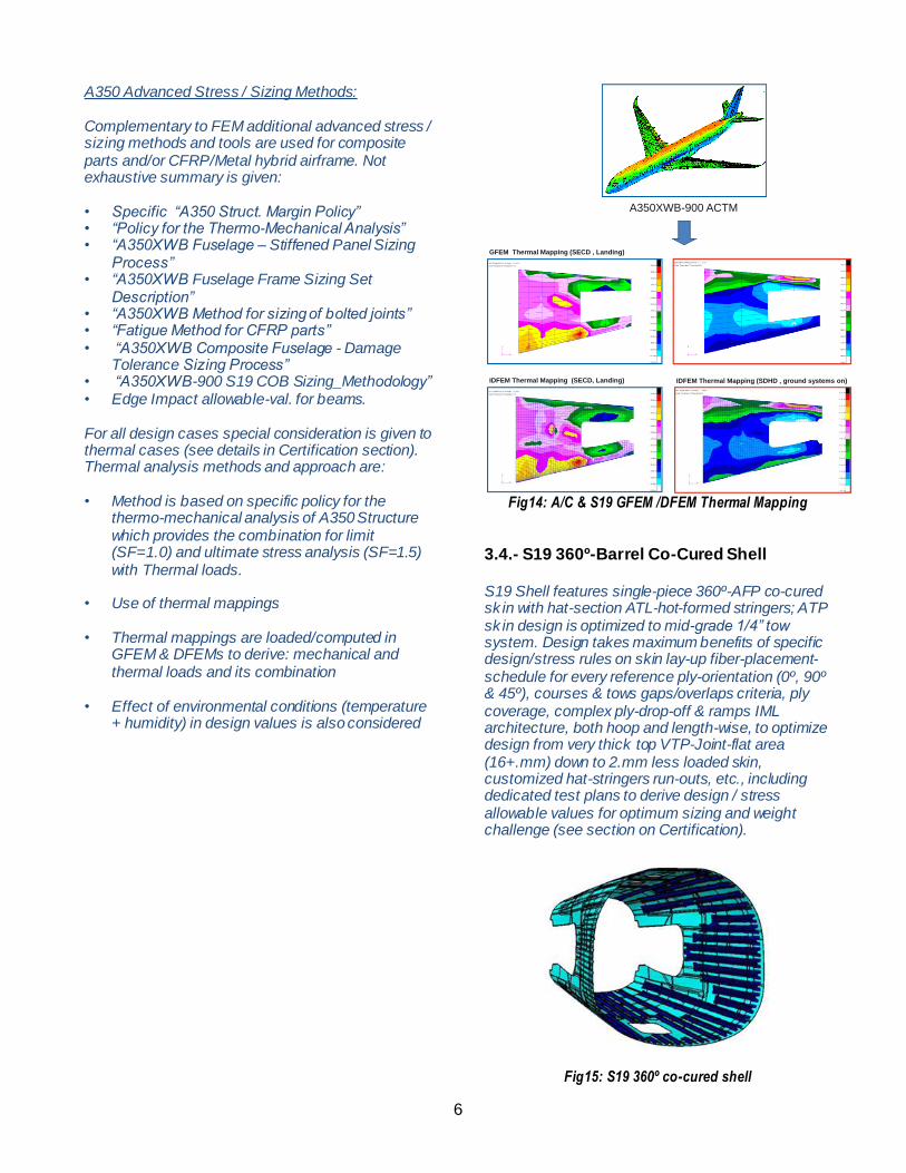
A350 Advanced Stress / Sizing Methods: Complementary to FEM additional advanced stress / sizing methods and tools are used for composite parts and/or CFRP/Metal hybrid airframe. Not exhaustive summary is given: • Specific “A350 Struct. Margin Policy” • “Policy for the Thermo-Mechanical Analysis” • “A350XWB Fuselage – Stiffened Panel Sizing
Process” • “A350XWB Fuselage Frame Sizing Set
Description” • “A350XWB Method for sizing of bolted joints” • “Fatigue Method for CFRP parts” • “A350XWB Composite Fuselage - Damage
Tolerance Sizing Process” • “A350XWB-900 S19 COB Sizing_Methodology” • Edge Impact allowable-val. for beams. For all design cases special consideration is given to thermal cases (see details in Certification section). Thermal analysis methods and approach are: • Method is based on specific policy for the
thermo-mechanical analysis of A350 Structure which provides the combination for limit (SF=1.0) and ultimate stress analysis (SF=1.5) with Thermal loads.
• Use of thermal mappings
• Thermal mappings are loaded/computed in
GFEM & DFEMs to derive: mechanical and thermal loads and its combination
• Effect of environmental conditions (temperature
+ humidity) in design values is also considered
Fig14: A/C & S19 GFEM /DFEM Thermal Mapping
3.4.- S19 360º-Barrel Co-Cured Shell S19 Shell features single-piece 360º-AFP co-cured sk in with hat-section ATL-hot-formed stringers; ATP sk in design is optimized to mid-grade 1/4’’ tow system. Design takes maximum benefits of specific design/stress rules on skin lay-up fiber-placement-schedule for every reference ply-orientation (0º, 90º & 45º), courses & tows gaps/overlaps criteria, ply coverage, complex ply-drop-off & ramps IML architecture, both hoop and length-wise, to optimize design from very thick top VTP-Joint-flat area (16+.mm) down to 2.mm less loaded skin, customized hat-stringers run-outs, etc., including dedicated test plans to derive design / stress allowable values for optimum sizing and weight challenge (see section on Certification).
Fig15: S19 360º co-cured shell
A350XWB-900 ACTM
GFEM Thermal Mapping (SECD , Landing)
IDFEM Thermal Mapping (SECD, Landing) IDFEM Thermal Mapping (SDHD , ground systems on)

7
Shell design is also driven by special requirements concerning the manufacturing process, curing-tool design and industrial systems, with great challenges due aggressive & complex 3D-tool-mandrel geometry at HTP side interfaces and stringers arrangement compatible with the curing & demoulding process (see details latter). Design to manufacturing is managed by Airbus’ concurrent process based upon so-called Data-Drops (DD’s) schedule, with progressive Design/Sizing data release according to detailed technical criteria and data agreed and endorsed among the key actors as SDW + ME + Program-PDT.
Fig16: Half-co-cured shell IML & Stringer
3.5.- S19 Integral Co-Injected RTM-Frame RTM-Door-Frame design is one of the largest parts in current airline design made by Injection/Infusion technologies. It’s designed as single co-injected part made out of: 2 longerons, 2 lintels and 4 frame sectors. Door-Frame integral design reduces heavy large bolted joints with direct benefits on weight and RC’s saving. Integrated frame design is optimized for RTM6 resin and Woven Fabric & UD-Fabric textiles and has customized ply-by-ply and 3D Cad/Cam design tools.
Door-frame stress sizing is done with GFEM and customized DFEM, including idealization features for Beams and “diamond-joints” checks, with parallel optimization checks based on ViFST.
Fig17: S19 THSA Door-Frame FEM analysis approach
4. S19 Certification approach Regulations Requirements are fundamental to airframe Design, Certification. A350XWB airframe Certification is based upon full integrated test Plan (Static and F&DT), as well as stress/design reliable and validated methods and derivation of design allowable values. Building-block “Pyramid of Tests” approach includes: Generic tests for derivation of Design Values Specific Element Tests to validate design
features (panels, Elements; Stat. + F&DT) Customized Thermal Tests Full-Scale/Component Tests (Static + F&DT)

8
Fig18: S19 Certification Test Pyramid
S19 design poses significant certification challenges due to the use of brand-new material and procesess, and to its hybrid structure design with Metal (Alu/Ti) and CFRP elements. Certification Plan addresses following airframe key aspects: • Design Values and Methods developed for
specific features of S19, validated with relevant tests at different level of pyramid
• FEMs with different detail levels, appropriate to analyze the different behavior (from global to local), and correlated with tests
• Selection of critical load cases, in combination with the correlated thermal case
• Validation by analysis, supported by tests at different level of the pyramid, of the final design
Fig19: S19 Sizing Load Cases
Fig20: CFRP parts Sizing Criteria & Load Cases
Thermal loading and sizing issues, due to the hybrid Alu/CFRP design are addressed and validated by tests.
Fig21: S19 Thermal Analysis Approach
LEVEL 1
LEVEL 2
LEVEL 3
LEVEL 4
LEVEL 5
ES
EF3
S19 Stringer Run-Out
S19 Integ. THSA Door Frame
S19-HTP Rear Interface
S19 Stiffened Curved Panels
S19 CFRP Beams
S19 CFRP Lugs
S18-19 Hoop
Joint