ec310 notes version 2018.2 book 2 of 3 department of ... · department of electrical and computer...
TRANSCRIPT

EC310 Notes
Version 2018.2
BOOK 2 of 3
Department of Electrical and Computer Engineering

THIS PAGE INTENTIONALLY LEFT BLANK

i
Contents
Part II: The Network ............................................................................................................................... 213 Chapter 11: The TCP/IP Model .......................................................................................................... 215
CH. 11 Problems ............................................................................................................................. 229 Chapter 12: The Physical Layer (Layer 1) .......................................................................................... 231
CH. 12 Problems ............................................................................................................................. 241 Security Exercise 12 ....................................................................................................................... 243
Chapter 13: Data Link Layer, LAN’s and Ethernet ............................................................................ 251 CH. 13 Problems ............................................................................................................................. 263
Security Exercise 13 ....................................................................................................................... 265 Chapter 14: The Network Layer and Internet Protocol ...................................................................... 273
CH. 14 Problems ............................................................................................................................. 285 Security Exercise 14 ....................................................................................................................... 287
Chapter 15: Address Resolution Protocol and Routing Mechanics .................................................... 293
CH. 15 Problems ............................................................................................................................. 309 Security Exercise 15 ....................................................................................................................... 311
Chapter 16: Autonomous Systems and Intranet Routing .................................................................... 317 CH. 16 Problems ............................................................................................................................. 327 Security Exercise 16 ....................................................................................................................... 329
Chapter 17: The Man-In-The-Middle Attack ..................................................................................... 341 CH. 17 Problems ............................................................................................................................. 349
Security Exercise 17 ....................................................................................................................... 351 Chapter 18: Inter-domain Routing and Routed Wide Area MITM .................................................... 357
CH. 18 Problems ............................................................................................................................. 371 Security Exercise 18 ....................................................................................................................... 373
Authorship Notes
The following faculty members developed content, reviewed the course material and offered many helpful suggestions which
greatly improved the course: Agur Adams, Chris Anderson, Jessie Atwood, Jay Benson, Justin Blanco, Dane Brown, Audrey
Callanan, Gregory Coxson, Rita Doerr, Kevin Fairbanks, Rob Ives, Ryan Kelly, Richard Kopka, Matt Rehberg, Nicholas
Rosasco, John Roth, Keneth Templin, Patrick Vincent, William Ortiz, Ryan Whitty, Jennie Wood, Currie Wooten.
Acknowledgements
Beth Haneke offered expert advice throughout the process and greatly assisted with editing, formatting, and preparing the
manuscript for print.

THIS PAGE INTENTIONALLY LEFT BLANK

213
Part II: The Network
You are now experts on the security of an individual host.
Well−okay−expert-ish.
In this module you will gain an in-depth understanding of how the Internet works today and how fragile its core infrastructure
really is. You will learn about the fundamental networking technologies and the design principles behind the Internet, and
you will examine the security risks associated with internetworking.

214
THIS PAGE INTENTIONALLY LEFT BLANK

Chapter 11: The TCP/IP Model
Objectives:
(a) Describe the TCP/IP model, the functions performed by each layer, and the process of encapsulation.
(b) Define the function of a protocol.
EC310 is divided into three sections. We finished Part I: The Host, where we examined specific threats against an individual
computer in isolation from a network, focusing on the buffer overflow attack.
We now move on to Part II: The Network, where you will gain an in-depth understanding of how the Internet works today
and how fragile its core infrastructure really is.
After we complete the network section, we will move to our final unit, Part III: Wireless, where you will gain an appreciation
for the unique security threats inherent when operating in a wireless environment.
1. An Example of Network Fragility
The Internet was actually designed in the 1970s, long before its security became a concern. As the Internet's protocols were
being put in place, the underlying assumption was that the Internet would only be used by cooperating scientists and
academics who had no reasons to act with malice toward each other. Since security was not an issue, many of the underlying
Internet protocols, to this day, rely on a measure of trust and cooperation among the parties that regulate and control the
Internet's infrastructure.
This is particularly true when routing traffic through the Internet. It should be obvious that it is beneficial to route traffic from
source to destination using the best path. It would not make sense to route Internet traffic from Boston to New York via
Tokyo. The decisions concerning which routes are best for reaching various destinations are largely determined through
cooperation among the Internet's routers. Basically, each router tries to determine how easily it can get to various particular
destinations, and the routers exchange this information with each other. Through this cooperative exchange, a consensus
emerges over which routes are optimal to reach specific destinations from any starting point.
So, with so much cooperation, what could go wrong?
In 2008, A Dutch politician named Geert Wilders released a three and a half minute trailer for a controversial short film that
explored the ties between Koranic teachings and terrorism. The trailer and the film (which was subsequently released in
2009) were both critical of Islam and created an uproar in many Muslim-dominated countries. The film trailer also caused an
uproar that reverberated throughout the global Internet. 1
Pakistanis marched through Karachi to protest the video. In response, the Pakistani government ordered that YouTube be
blocked in all of Pakistan to prevent Pakistani citizens from viewing the offending movie trailer.
On Sunday, February 4th, 2008, Pakistan Telecom, the national ISP, complied with the order to block YouTube by
advertising itself to the rest of the world as the best route to reach YouTube. In essence, Pakistan Telecom announced to the
all other routers on the Internet: "If you want to reach YouTube, I can get you there nearly instantaneously—so if you want to
get to YouTube quick, forward your request to Pakistan Telecom." A person trying to access YouTube from home in
Karachi had the request routed to Pakistan Telecom, who in turn did not allow access to YouTube.
But the repercussions extended far beyond the borders of Pakistan. The Internet's routers—throughout the world—assuming
that the information was truthful, autonomously adjusted their optimal route to YouTube by sending all worldwide YouTube
requests to Pakistan Telecom. Because of the level of trust among the Internet's key players, no verification was made to
check if the new route made any sense. Pakistan Telecom—needless to say—simply discarded these requests from people
around the world wanting to get to YouTube. Instead of the usual cat videos or clips of old people falling down the stairs,
viewers were greeted with this far less entertaining display:
1 The interested midshipman can view the controversial movie trailer here: http://www.youtube.com/watch?v=jKCZfnpU1uc

Chapter 11: The TCP/IP Model
216
It should be noted that subsequent investigations revealed that Pakistan Telecom only intended to block YouTube within
Pakistan; they did not foresee that their actions would affect the broader Internet. Also, Pakistan Telecom did not disrupt the
correct routing information that was all-the-while promulgated by YouTube's servers and Internet routers; it simply
promulgated "better" routing information.
In any event, the YouTube outage affected the world and lasted for over two hours.
In a similar incident, on Christmas Eve in 2004, a company in Turkey inadvertently announced that it was the best path to
everything on the Internet. A report by Todd Underwood of the Internet Management firm Renesys concluded that "Virtually
everything on the Internet was unreachable for someone: banks, governments, ecommerce sites, businesses, universities–no
one escaped the damage." This event lasted several hours.
Worldwide availability of YouTube drops from 100% to 0% for an hour, and does not fully recover for over two hours. (Source: Keynote Systems)
Likewise, in an event that one can only assume was accidental, Con Edison—the electric company for New York City—
announced that it was the best route to reach Martha Stewart Living Omnimedia. For several hours, individuals who wanted
to check on the right color salad bowl to use at a springtime picnic were routed to the gritty website of a public service utility.
This is a problem affecting the Internet right now. The ease with which a hacker can manipulate routing tables to intercept or
redirect Internet traffic remains startling. In November 2013, Renesys noted that on 38 distinct occasions over the period
February 2013-November 2013, Internet traffic affecting major financial institutions and government agencies was
inexplicably routed through Belarus. The graph below shows the route taken by a banking transaction between New York
and Los Angeles that was mysteriously routed through Belarus.

Chapter 11: The TCP/IP Model
217
These routing calamities are not limited to the US. On Tuesday January 21, 2014, most of China's 500 million Internet users
had all of their Internet traffic redirected to a nondescript residential building in Cheyenne, Wyoming. In short, China was cut
off from the Internet for about eight hours.
Why does the Internet work this way? We will pull apart the infrastructure of this mysterious creature called the Internet to
better answer this question.
2. Layers
2.1 Divide and Conquer Computer networks are exceedingly complex. To enable effective communication we must attempt
to coherently organize the various functions that must be carried out. To reduce the complexity in designing networks, and to
make the task more manageable, networks are organized as a series of layers. The guiding principles are:
Each layer performs only a few specific, well-defined functions. This simplifies the design.
The layers are built, one on top of the next.
Each layer performs a service for the layer above it. However, how a layer does its job is not known by the layer
above. This permits later modifications. A single piece of software that provides all networking capability would be
very hard to modify later.
This notion of organizing a network into a series of layers is similar (conceptually) to the way that programs are organized
into a series of modular functions.
2.2 A practical example Suppose you want to send an email to your friend. You have email application software on your
computer, and your friend has email application software on her computer. Thus, you can compose an email on your
computer using your application, and if this email was to land at the doorstep of the email application on your friend's
computer, she could then read it. But… how does this email get from your email application program to your friend's email
application program? They are separated by a geographic distance. With networks we must think small to large!
You have no idea how to forward an email to your friend so you consult with your friend, the Transport layer.

Chapter 11: The TCP/IP Model
218
Although your friend Transport was willing to help, and has taken custody of your email message, he quickly realizes he
cannot do it all! Handing off your email to the transport layer won’t accomplish the entire process but the transport layer can
perform his assigned functions before handing continuing. He does what he can and contacts his friend, the Network layer.
You the Transport layer decide to leave your problem (which was actually Application's problem) with your friend Network
to see if they can build on your efforts and get this email to the distant end.

Chapter 11: The TCP/IP Model
219
Much like before, Network is willing to play a role, and has taken custody of the email message, he quickly realizes he
cannot proceed further. Not knowing what to do, he contacts his friend, the Data Link layer.
You the Network layer decide to do your part and then continue this game of telephone and leave the email with your friend
Data Link to see if they can get this email to the distant end.
Although your friend Data Link was willing to help, and has taken custody of the email message, he quickly realizes he needs
his friend, the Physical Layer, to help.

Chapter 11: The TCP/IP Model
220
But here is the important point: The physical layers are able to successfully communicate:
So, the original email leaves the email application on the left, travels down the five layers (Application, Transport, Network,
Data Link and Physical) and each layer performs their assigned function as the email application transits. It then travels
across a physical medium, landing in at the destination computer. At the destination computer the message transits up the five
layers, eventually arriving at the email application of your friend's computer, on the right.
In light of the picture above, recall the guiding principles we mentioned at the outset:
Each layer performs only a few specific, well-defined functions. This simplifies the design. For example, in the
email scenario above, the transport layer only worried about getting the message delivered to the right application
(the email application) and having it arrive correctly. The transport layer did not worry about routing (that was left
to the network layer) or whether logical one should be represented by +5 volts (that was left to the physical layer).
The layers are built, one on top of the next.
Each layer performs a service for the layer above it. However, how a layer does its job is not known by the layer
above. This permits later modifications. For example, the network layer is tasked with determining the best route
from source to destination, but the choice of algorithm used should be of no consequence to the transport layer. If
we were to change the network layer routing algorithm from a link-state algorithm to a distance-vector algorithm,
the transport layer should not even be aware of this.
If we decided to try to build one big honking software/hardware contraption that does everything at once (i.e., just put the
whole kit and kaboodle into one layer), the resulting mess would be extremely difficult to modify later. Splitting functions
into layers simplifies the design. Additionally, it allows us to replace a layer with a different implementation that
accomplishes the same task using a different mechanism, without disturbing the other layers.

Chapter 11: The TCP/IP Model
221
3. Protocols
It is important to note that actual communication takes place only between the five layers in the same machine and the
physical layers of adjacent machines. In the picture on the preceding page, the dark black lines signify the only true transfer
of data—i.e., the only real communication. Apart from the physical layer, no data are actually directly transferred from layer
n on one machine to layer n on the other machine. Instead, each layer passes information/data only to the layer immediately
above or below it.
In a real sense, though, it seems as if the email application in the machine on the left in the picture above is communicating
directly with the email application in the machine on the right. Similarly, it seems as if the transport layer on the left is
communicating directly with the transport layer on the right. In fact, it seems as if each layer on the left is communicating
with its peer layer on the right. This communication is termed virtual communication.
A layer in one machine communicates with the corresponding layer on the other machine using that layer's protocol. For
example, the transport layer of the machine on the left communicates with the transport layer of the machine on the right
using the transport layer protocol.
A protocol is an agreement or a set of rules governing how a task or process should be carried out. Each layer has assigned
functionality and the protocol we employ must accomplish this tasks. There can even be multiple protocols that accomplish
the same function assigned to a layer in different ways.
We mentioned that one of the functions of the transport layer is to ensure that data is delivered without errors. The transport
layers on both machines might, for example, use the Hamming code to ensure that errors are detected and corrected. In this
case, the agreed upon protocol for error detection at the transport layer is the Hamming code. If the transport layer in the
machine on the left is using the Hamming code to detect errors, but the machine on the right is using the CRC algorithm (a
different error detection protocol) to detect errors, communication will not be successful. The peer entities at each layer must
agree on the protocol.
As another example, we mentioned that one of the functions of the physical layer is to determine how logical 1 and logical 0
are represented. If the physical layer of the machine on the left is representing logical one by +5 volts and logical zero as -5
volts, but the machine on the right is doing just the opposite—representing logical one as -5 volts and logical zero as +5
volts—communication will not be successful. The peer entities at each layer must agree on the protocol.
To recap, two machines might be connected, but if complimentary protocols are not in place at each layer to accomplish the
virtual communication between the corresponding layers on the sending and receiving end, there will be no communication.
If two people are talking to (at) each other, one who only speaks English and the other who speaks only Chinese, no
successful communication will occur because the two speakers are not using the same protocol (in this case, the language). If
agreed upon protocols are in place, then the entities on the same layers on different machines (i.e., peer entities) carry on a
conversation using the agreed-upon protocol.
3.1 Key terms
Network Architecture. The set of layers and protocols is termed a network architecture.
Protocol Stacks. The protocols used by a system are called the system's protocol stack.

Chapter 11: The TCP/IP Model
222
4. Tanenbaum’s Philosopher Analogy2
The various terms—layers, protocols, virtual communication, etc.—may seem confusing, so let's use these same concepts in
a non-networking setting. Two philosophers wish to communicate, but they are far apart and they don’t speak the same
language. So they each hire a translator who translates their messages into a common language. The translators then pass
their messages along through secretaries, who can communicate through a common interface. Note that it doesn’t matter what
the common interface is (fax, phone, e-mail) as long as both secretaries use the same interface. Similarly, it doesn’t matter
what the common language is (Dutch, English, Swahili) as long as the translators agree. Also, note that neither the secretaries
nor the philosophers need know what the language choice was. Just like the philosophers and the translators don’t need to
know how the message is transmitted. Each layer just needs to understand its interface to the next layer.
Tanenbaum’s Philosopher Analogy. From Andrew S. Tanenbaum, Computer Networks, 4th ed., Prentice Hall, 2003
So… how many layers exist in this scheme? You should agree that we have three layers, which we might call the Philosopher
Layer, the Translator Layer and the Secretary Layer.
Entities at the same layer must use the same protocol, or communication will not be successful. If the translator on the left
translates messages into French while the translator on the right is expecting to receive messages in German, no deep
philosophical thoughts will be exchanged between the philosophers. If the secretary on the left sends messages by fax, but the
secretary on the right is only expecting messages by email, no philosophical thoughts will be shared.
Think about how layering helps us in this scenario. We can easily replace a layer with a different implementation that
accomplishes the same task using a different mechanism, without disturbing the other layers. For example, the two translators
might shift from Latin to Hebrew. As long as the two translators agree, the philosophers and secretaries will not be concerned
(they might not even be aware of the shift in the language protocol). Similarly, the two secretaries might agree to shift from
the fax protocol to the email protocol without even informing the translators or philosophers.
2 See: Andrew S. Tanenbaum, Computer Networks, 4th ed., Prentice Hall, 2003 (pages 28-29)

Chapter 11: The TCP/IP Model
223
5. Encapsulation
So think again… how does a layer do its job? Here's how:
At the sending end, each layer puts a header on the message received from the layer above. The header contains
information necessary for the protocol to do its job.
At the receiving end, each layer strips off the corresponding header and forwards the rest up to the layer above.
The application layer passes its message to the transport layer. The transport layer attaches some number of bits, shown as T
in the picture above and sends this onward to the network layer. The network layer then appends some number of bits, shown
as N in the picture above, and so on, down the protocol stack. What actually gets transmitted across the physical layer from
the source to the destination is:
Note also that at each layer, the resulting block of data has a specific name, so a message is encapsulated into a segment, a
segment into a packet, and a packet into a frame.3 More on this later.
3 At the Physical Layer, we don’t refer to blocks of data, but bits.
data block name
message
segment
packet (also datagram)
frame
bit*
*not a block of data

Chapter 11: The TCP/IP Model
224
At the destination the encapsulation process is reversed (decapsulation) as described in the diagram below.
The destination physical layer removes the bits marked P and passes the result up to the data link layer. The data link layer
removed the bits marked D and uses these bits to implement the data link protocol. Then the result is passed to the network
layer which removes the bits marked N and uses these bits to implement the network layer protocol, and so forth.
Practice Problem 11.1
Suppose an application entity generates 2904 bytes of data. Suppose also that by the time this data arrives at the data link
layer, 96 bytes of header information has been added. At the data link layer, the maximum frame size is 1518 bytes, of which
18 bytes are its header. (a) How many frames will be used? (b) How many total bytes must be transmitted? (c) What
percentage of the transmitted bits are from the application layer?
Solution:
Practice Problem 11.2
Let’s consider the same problem, this time with 2905 bytes of data generated at the application layer. Suppose also that by
the time this data arrives at the data link layer, 96 bytes of header information has been added. At the data link layer, the
maximum frame size is 1518 bytes, of which 18 bytes are its header. (a) How many frames will be used? (b) How many total
bytes must be transmitted? (c) What percentage of the transmitted bits are from the application layer?
Solution:
data block name
message
segment
packet (also datagram)
frame
bit*
*not a block of data

Chapter 11: The TCP/IP Model
225
6. The TCP/IP Reference Model
The model we used is Section 2.2 was not chosen randomly! This model, repeated below, is termed the TCP/IP4 reference
model.
You should memorize this model! Use a mnemonic if it helps. One possibility is the West Point motto: Please Do Not Trash
Army.
6.1 A Five Layer Model The model we will use is the TCP/IP reference model, which consists of five layers. We list the
layer, then describe some of the functions usually assigned to the layer.
The application layer is concerned with general purpose facilities that involve communications:
SMTP for email
HTTP for accessing the web
FTP for file transfer
SSH and TELNET for remote log in
DNS for directory assistance
SNMP for network management
Several other functions are also conceptually placed at the application layer:
Encoding. For example: Are we using EBCDIC or ASCII? Are we using Big Endian or Little Endian?
Encryption
Compression
Blocks of data at the application layer are termed messages.
The application layer uses end-to-end protocols that do not recognize the existence of an underlying network. The notion of a
networking protocol being end-to-end can be somewhat confusing, so it may be helpful to recast the notion in terms of a
different network you are familiar with: the telephone network.
Suppose you (in Annapolis) are having a phone conversation with your friend (in Florida) over the plain-old-telephone
system. Suppose you use some acronyms in your conversation. Instead of saying, United States Naval Academy you say
USNA. Instead of saying Midshipmen Regulations Manual you say MIDREGS. Instead of saying Brigade Medical Unit, you
say BMU. Instead of saying Greatest Bestest Course Ever you say Cyber-2. Using acronyms is a form of data compression.
You are conveying the exact same information to your friend, but you are doing this with fewer syllables.
Now, ask yourself: Does the Phone Company—the wires, the switching stations, the fiber optic cables—care if you are using
acronyms to compress your data? The answer is, of course: No. The phone company does not care, and is not even aware, of
the use of compression in your voice conversation. It only matters to the end users who are actually speaking on the
telephone.
4 TCP – Transmission Control Protocol. IP – Internet Protocol.
The application layer

Chapter 11: The TCP/IP Model
226
Now, let's switch back to computer networks. We mentioned that the application layer can implement compression. As with
phones, so with computers: only the end points will care, or even be aware of the fact that data is being compressed. The
underlying computer network is oblivious to this.
Consider another example: Encoding. Encoding is done at the application layer, and an encoding protocol is end-to-end: the
network is not aware of the encoding scheme. In a telephone conversation, the encoding scheme might be the language that
you and your friend converse in. The phone company's network does not care if your conversation is in English or Spanish;
this is a concern only to the end users.
So, again, the application layer protocols are end-to-end.
Ideally, the transport layer is responsible for the end-to-end transfer of data from a process in the source to a process at the
destination, independent of the network. Put another way, ideally the transport layer uses end-to-end protocols that do not
recognize the existence of an underlying network.
Blocks of data at the transport layer are termed segments.
Some tasks of the transport layer:
End-to-end flow control
End-to-end error control
End-to-end congestion control 5
Multiplexing- sending several transport layer connections over a single network layer connection.
The phone company analogy is useful again for recognizing that the protocols at the transport layer are end-to-end. Does the
phone company's network care if the person on the receiving end says: "Slow down, I'm trying to write this down" (Flow
control)? Does the phone company's network care if the person on the receiving end says: "Let me read this back to you to
make sure I've got it" (Error control)? The answers: No and No; these are end-to-end concerns.
In the next three layers, the protocols are between adjacent entities (machine-router, router-router, router-machine)
The network layer is concerned with transferring data across a communications network from a source computer to a
destination computer. This is the first layer that recognizes the existence of a network.
Blocks of data at the network layer are termed packets or datagrams. Tasks for the network layer include:
Routing
Internetworking-interconnecting distinct networks that use different protocols (different addressing schemes,
different packet sizes, etc.)
The data link layer is concerned with transferring data across a single link connecting two nodes.
Blocks of data at the data link layer are termed frames. Tasks for the data link layer include:
Setting frame boundaries
Error control (to make a real link into an error-free link)
Link flow control (to stop a fast transmitter from drowning a slow receiver)
Control access to shared channels-the Multiple Access Problem
The physical layer is concerned with sending bits over a channel: i.e., the mechanical and electrical considerations. Blocks of
data at the physical layer are termed bits… so we're not really talking about blocks!
6.2 The Big Picture Again
In each layer, a process on one computer communicates with a peer process on another computer using that layer's
protocol. This communication is virtual.
5 The ideal separation of layers breaks down in practice. Although congestion control algorithms are end-to-end algorithms,
they are designed to alleviate congestion in a network.
The transport layer
The network layer
The data link layer
The physical layer

Chapter 11: The TCP/IP Model
227
The layer n + 1 entity uses the services provided by layer n. Layer n + 1 only cares that layer n performs the desired
service. How layer n goes about performing the service (i.e., the implementation) is of no interest to layer n + 1.
The layer n protocol does not interpret the information passed to it by layer n + 1.
At the sending end, each layer puts a header on the message received from the layer above. The header contains
information necessary for the protocol to do its job. At the receiving end, each layer strips off the corresponding header
and forwards the rest up to the layer above. For example, the picture below focuses on the network layer, and we can
see that a segment from the transport layer (in gray) is encapsulated into a packet at the network later (by adding the
header shown in pink). This packet is then sent to the data link layer.
Source: Forouzan, Data Communications and Networking, 4th ed., McGraw Hill, 2007
The process will continue. The packet at the network layer will be encapsulated into a frame at the data link layer.
See PowerPoint slide "Layers" on the course website.
As we discuss the security issues in the TCP/IP Model, we must keep in mind that networks must remain useful. All ITSD
network security problems at the Naval Academy could be instantly solved by simply preventing all midshipman, faculty and
staff from using computers and computer networks! That is not a good solution. We want to be able to use our networks, but
in a safe and secure manner.

Chapter 11: The TCP/IP Model
228
Practice Problem 11.3
You caught one of your crewmembers attempting to gamble online on one of your ship's computers. After putting him on
report, he tells you that the computer did not seem to be working. For each of the network problems below, state which layer
of the TCP/IP model the problem resides in.
(a) Our computer cannot communicate with a website due to an error in the routing algorithm used by an intermediate
node.
(b) Our computer cannot communicate with a website because your crewmember spilled his drink on the cable adapter,
causing a short.
(c) Our computer cannot communicate with a website due to the fact that the two users (us and them) are using different
end-to-end error control algorithms.
(d) Our computer cannot communicate with a website because we are using the XYZ-encryption algorithm, but the website
server is using the (incompatible) ABC-decryption algorithm.
Solution: (a) (c)
(b) (d)
Practice Problem 11.4
For the boxes below, fill in the names of the layers for the TCP/IP - 5 layer reference model and then place the appropriate
letter in the blank associated with the layer for the proper description of its services.
Layer 5 _____ ______
Layer 4 _____ ______
Layer 3 _____ ______
Layer 2 _____ ______
Layer 1 _____ ______
a) Provides a definition of mechanical and electrical standards for communication system
b) Concerned with transferring packets across a communication network
c) Responsible for end to end transfer of data
d) Primary function is to format and transfer files between communication message and the user’s software
e) Frames of data are transferred across a single link

Chapter 11: The TCP/IP Model
229
CH. 11 Problems
1. The basic unit of information sent at the application layer is termed a message. Write down the term that is used to
denote the basic unit of information sent at each of the layers listed below:
(a) transport layer
(b) network layer
(c) data link layer
(d) physical layer
2. What is the name used for the data unit that is encapsulated within a data link frame?
3. What is the name for the data unit that is decapsulated from a packet?
4. State the layer of the TCP/IP reference model that is responsible for each of the following tasks:
(a) Determining the route from source to destination
(b) Handling a frame received from an adjacent computer
(c) Detecting end-to-end errors
(d) Transmitting +5 volts to denote logical 1 and -5 volts to denote logical 0
5. Suppose an application entity sends an L-byte message to its peer entity. The layers in the TCP/IP model add a total of
58 bytes of overhead (header and trailer).
(a) What percentage of the physical layer bits corresponds to the application message if L = 100 bytes.
(b) Repeat part a for L = 1000 bytes.
6. List the layers of the TCP/IP model and select from the list below the letter that best describes the main function of each
layer.
(a) Transfers frames across a single link connecting two nodes
(b) Responsible for end-to-end flow, error, and congestion control
(c) Sends bits over a channel
(d) Processes that provide services to users such as HTTP and FTP
(e) Responsible for routing packets and internetworking

230
THIS PAGE INTENTIONALLY LEFT BLANK

Chapter 12: The Physical Layer (Layer 1)
Objectives:
(a) Define the term signal and differentiate between analog and digital signals.
(b) Explain the differences between serial and parallel data transmission and the advantages of each.
(c) Differentiate between guided media and unguided media and specify the applications of each.
(d) Demonstrate the ability to examine a voltage waveform that represents an ASCII character on an oscilloscope and using
an ASCII table, determine which character is present.
(e) Determine the waveform that would be transmitted in asynchronous serial communication for a given ASCII character.
1. Introduction
The Physical layer is the physical interface between a data transmission device (e.g. computer) and the transmission medium.
The Protocol Data Unit (PDU) at the Physical Layer are termed bits. Bits? Bits! Yes, these are the same binary digits (bits)
that we learned about back on the first day of class. Recall that our computers are only capable of storing data in two states.
So if we wish to transmit any of this information, then we will be transmitting bits. Streaming video, satellite radio, and email
are all examples of data, which will be generated at the application layer in the TCP/IP model and encapsulated with layer
specific headers until eventually arriving at the physical layer. At the physical layer the distinction between the layer specific
headers is disregarded: it all needs to be transmitted! The physical layer at the receiving end will then receive the bits, and
each subsequent layer will move through the process of decapsulation. The physical layer is solely focused on moving data in
the form of electric or electromagnetic signals across a transmission medium.
The terms analog and digital correspond, roughly, to continuous and discrete. These two terms are used in data
communications in at least three contexts that affect operations at the physical layer: data, signals and transmission.
2. Analog and Digital Data
We define data as information that has been changed into a form that is efficient for storage, analysis or communication.
2.1 Analog Data At this point in the course we are thinking binary! But of course it as also possible that information is
analog. Analog data takes on continuous values in some interval. An example of analog data would be audio, such as the
vibrations of a microphone’s diaphragm as someone speaks, or music is played. The typical human speech frequency range is
between approximately 300 Hz and 3000 Hz. The frequency and amplitude of the data change on a continuous interval as
someone speaks in a high or low pitch, loudly or quietly. This is not what comes to mind when we are thinking of
networking, but the many of the same principles apply and thus we include analog in our discussion here.
2.2 Digital Data Digital data takes on discrete values at discrete intervals. A familiar example of digital data would be the
bits in text or ASCII character streams, or the bits that make up a digital image such as a jpeg image. We recall from the Host
section that each character on a keyboard is stored using the ASCII code in binary. When transmitted, this digital data (i.e.,
the bits) is often called a bitstream.
3. Analog and Digital Signals
Communication at the physical layer means exchanging signals between the transmitter and receiver. A signal is a function
that conveys information. In communications, signals are typically electrical or electromagnetic representations of data. We
use signals to actually transmit data. Signals are considered either analog or digital, and the speed with which information is
being transmitted is referred to as data rate.
3.1 Analog Signals An analog signal is a continuously varying electrical or electromagnetic wave that may be propagated
over a variety of media, either guided or unguided (defined later). An analog signal can take on an infinite number of values
(i.e., a continuum of values) between some maximum and minimum level, and last any amount of time. Some examples of
analog signals are shown in the following plots. At any time (along the x-axis), the signal can take on any voltage value in the
range from the minimum to the maximum. Note: the minimum and maximum is typically -1 volt and +1 volt for audio
signals.

Chapter 12: The Physical Layer
232
Also note that a communication system that utilizes analog signals to transmit the information is termed an analog
communication system.
3.2 Digital Signals A digital signal is any signal that can be used to represent digital data, such as a sequence of voltage
pulses transmitted over a guided medium. Digital signals can change only at discrete time intervals. Some examples of digital
signals are shown in the figure below. With digital signals, data rate is also called bit rate (number of bits per second
transmitted) or baud rate (number of signals per second transmitted).
A communication system that uses digital signals to transmit the information is termed a digital communication system. It is
possible to use a digital communication system to transmit analog information, however the analog signals must be converted
to digital signals first. This process is called analog-to-digital conversion, and how this is accomplished is discussed in the
Wireless section of the course. In this case, at the receiver, a digital-to-analog conversion must occur to recreate the analog
signal.
4. Baseband and Bandpass Transmission
A communication system can be an analog system or a digital communication system, and at the same time can also be
categorized into one of two types depending on the range of frequencies of the signals that are used to transmit the
information. That is, the communication system can be a baseband system (low frequency) or a bandpass system (higher
frequency). In the Wireless section of the course, baseband and bandpass transmission and analyzing a signal’s frequency
content is further studied.
4.1 Baseband Transmission Baseband transmission assumes that the signal transmitted has information content that is low
frequency (called a baseband signal). Baseband signals can be analog or digital signals. Examples of baseband signals are
voice signals (analog), music signals (analog) and voltage pulses (digital). Let us focus on digital baseband transmission,
which is how communication is accomplished between two computers over a wired connection. In digital baseband
transmission, the bits are transmitted as voltage pulses, which again, are baseband signals. There are three key choices to
make in digital baseband transmission; timing, transmission mode and what kind of voltage pulses should be used.
4.1.1 Timing When two hosts communicate, they can communicate either synchronously or asynchronously. The distinction
between the two has to do with the timing of when each bit starts and stops in the communication.
Synchronous digital communications means that the transmitter and receiver are synchronized (i.e., use the same “clock”), so
both know exactly when each bit starts and stops. That is important when the receiver is checking its received voltage
waveform to determine if it is receiving a 1-bit or a 0-bit at any time. Bits can be transmitted and received at known, regular
time intervals. All communication that goes on inside a computer (e.g., when you want to run a program, moving the bytes of
a program’s instructions from the hard drive to RAM) is synchronous, since all components in your computer use the same
clock.
Asynchronous means that the transmitter and receiver do not use the same clock. In this case, the data is sent in “spurts” or
blocks of bits, and the time between each block is variable. This is the nature of how you might use your laptop’s keyboard to
communicate with another computer using telnet; your computer will probably have a different clock than the other
computer. But you don’t type at a constant rate all the time. So in asynchronous communication, the receiver must somehow
be made aware that data is coming.

Chapter 12: The Physical Layer
233
This is accomplished by the spurt of asynchronous bits always beginning with a start bit to let the receiver know that data is
coming. How does this work? Suppose we use a 5 volt pulse (“high”) for a 1-bit, and a 0 volt pulse (“low”) for a 0-bit, and
the normal voltage on the wire is 0 V. In this case the start bit would be a 1-bit (5 volt pulse) because the receiver could see
that the voltage on the wire jumped from its normal 0 volts up to 5 volts. The actual data bits follows the start bit. Both the
transmitter and receiver would have already agreed on how long each bit lasts (i.e., the bit rate), so when the start bit is
received, the receiver will know when it ends, and also when each other bit starts and ends.
In addition to a start bit, each block of data will also have a stop bit (or bits) to signify the end of the block. Furthermore, the
stop bit(s) are the logical opposite of the start bit; that is, if the start bit is a 0-bit, the stop bit(s) will be a 1-bit(s). This is so
that at the end of a block of data, the stop bit will not be confused with another start bit, which would signify the beginning of
more data. For our purposes, a block of data is considered the 8 bits that represent a particular ASCII character.
4.1.2 Transmission Mode When transmitting digital data it is possible to send it via two transmission modes, parallel and
serial. An example of each is depicted in the following figure.
Parallel Transmission In parallel transmission, multiple bits (usually 8 bits, in the above figure labeled D0 through D7) are
sent simultaneously on different channels within the same cable (i.e., wires within the same cable) or radio path. Both
transmitting and receiving side are synchronized to a clock, so each knows when each bit starts and stops. There is the
potential for a higher data rate, however there is a tradeoff: the speedup will generally cost more since multiple wires in a
cable cost more, and be more complex. Parallel transmission is used almost exclusively within a computer system. You may
remember looking at the physical components inside a computer in SY110 (Cyber 1) and seeing a ribbon cable, which is used
for parallel transmission.
Serial Transmission Serial transmission is the process of sending data one bit at a time, sequentially over a communications
channel. Serial communication is used for all long-haul communications and most computer networks because the cost of
cable and synchronization difficulties make parallel communication impractical. Serial transmission can be either
synchronous or asynchronous. As mentioned earlier, in asynchronous transmission, groups of bits are sent as independent
units with start bits and stop bits to ensure the receiver knows when the data begins and ends. Note that modern serial
communication standards (such as USB, Firewire, and Ethernet) offer very high speed serial transmission, so higher speed
transmission is becoming less of an advantage of parallel transmission.
Now let’s look a little closer at asynchronous serial digital baseband transmission and how it works.

Chapter 12: The Physical Layer
234
Practice Problem 12.1
Suppose you are engaged in asynchronous serial communication with another computer. The normal voltage on the wire is 0
V (low). The communication uses a start bit and a stop bit, and 8 bits for the ASCII character. If an oscilloscope (also called
o-scope) monitoring the voltage on the wire shows the following voltage signal is received, determine the bits transmitted
and the ASCII character. Important: on the o-scope display shown below, the little arrow at the top left points to the first bit
transmitted (the start bit), and the bits are transmitted in reverse order from what you might think (that is, the least significant
bit follows the start bit). Assume:
Normal voltage on the wire is low
A 1-bit is a low voltage pulse; so a 0-bit is high
A start bit is a 0-bit; so a stop bit is a 1-bit
ASCII characters use 8 data bits
The data bits (ASCII character bits) are transmitted in reverse order.
Solution:
Practice Problem 12.2
Using all the same parameters for asynchronous transmission you saw in Practice Problem 12.1, assume you strike your
keyboard hitting the letter “a” (lowercase ‘a’). Sketch the voltage signal transmitted down the wire AND indicate the
corresponding bits.
Solution:
4.1.3 Line Coding Line coding refers to the choice of shape of the voltage pulses to represent 0-bits and 1-bits. In the
simplest case, there is a one-to-one correspondence between bits and signal elements (the pulses); that is, each bit is a pulse.
The most common, and easiest way to transmit signals on copper wire is to use two different voltage levels, one level for a 1-

Chapter 12: The Physical Layer
235
bit, and a different level for a 0-bit. For example, one design is to have a 1-bit represented by a positive voltage pulse and a 0-
bit by no voltage pulse. Or, you could have a 1-bit represented by a positive voltage pulse and a 0-bit represented by a
negative going pulse. The receiver must know when it is receiving a new bit, and by checking the voltage on the wire, the
receiver is able to decode the digital signal back into a bitstream.
When designing a digital communication system that uses guided media and voltage pulses to represent the 1s and 0s, we
evaluate and choose the appropriate line coding scheme with the following parameters:
Signal bandwidth—Line coding signals have a frequency content that begins at 0 Hz and runs up to some higher
frequency depending on the time duration of the bits. Less higher frequency components means less bandwidth
required for transmission; the signal bandwidth should be suitable for the channel. In other words, wider voltage
pulses have a higher bandwidth.
Clocking—How easy is it for the receiver to tell when the bits start and stop if the transmitted signal contains a
multitude of consecutive 0-bits or 1-bits, resulting in a constant voltage on the wire? Transitions from low to high
voltage or vice versa help the receiver to maintain synchronization. Some line codes have more transitions than
others, resulting in a built-in synchronization method.
Error detection—Errors occur when the receiver thinks it is receiving a 0 when it is actually receiving a 1, or vice
versa. While error detection is not a function assigned to the physical layer, it can be useful to have a line coding
scheme that supports rapid error detection; some line codes have a built-in error detection capability
In the figure below are some common line coding schemes, with some comments about how their structure relates to the
three line code parameters listed above. Remember, all of the line coding schemes that follow are different ways to represent
1s and 0s with voltage pulses. In the figure, the word “polar” refers to whether the polarity of the pulses (if the voltages used
are positive, negative or 0 V), NRZ stands for “non-return to zero”, and means that positive or negative voltage pulses do not
return to a value of 0 V before the next bit starts, and RZ (“return to zero”) means that the voltage pulses do return to 0 V.
Unipolar NRZ: This is the kind of line coding
that was introduced earlier in this chapter,
and which will be used in SX12. The
bandwidth depends on the rate the bits are
transmitted (bit rate), and larger bit rate
means that the pulses are narrower, which
results in a larger bandwidth for the signal.
Also, it can be challenging for the receiver to
figure out where each bit starts and stops if
there is a long string of 0s or 1s being
transmitted, so this is not the best design for
clocking considerations. Polar NRZ is
similar.
Unipolar RZ: The pulses are narrower,
resulting in a larger bandwidth for the signal.
However, since the pulses return to 0 V
before the bit is finished transmitting, every
time a 1-bit is transmitted there is a transition
from high to low voltage. This aids the
receiver in clocking; keeping track of the
beginning and end of each bit.
Bipolar RZ: Is similar to Unipolar RZ, but the
alternate 1-bits are inverted. This means that
if the receiver should see consecutive
positive-going or negative-going pulses, an
error has occurred. Thus, this line code design
can help in error detection.
Manchester NRZ: For a 1-bit, the pulse is half positive voltage followed by half negative voltage, and for a 0-bit, the
pulse is half negative followed by half postive. This means that with every bit, there is a transition from low to high
Bits
:

Chapter 12: The Physical Layer
236
or high to low, is very good for clocking. The pulses, however, are half as wide as a unipolar NRZ or polar NRZ, so
the bandwidth of this signal is twice the bandwidth of the other NRZ designs.
4.2 Bandpass Transmission The term “Bandpass” refers to low frequency signals (baseband signals) that have had their
frequency content upshifted in frequency using a technique called modulation (discussed later in the course) so as to occupy a
higher range (band) of frequencies. This is done if the medium for the transmission is more suited to higher frequency
signals. How and why this is done will be covered in the Wireless portion of the course. Bandpass transmission systems can
be used to send either analog or digital data. Most commonly, signals are transmitted through the media as electromagnetic
(EM) waves.
A portion of the electromagnetic (EM) spectrum is of interest to us for wireless transmissions. Frequencies of 30 MHz-1 GHz
are referred to as the radio range. Microwave frequencies range from about 1 GHz to 40 GHz. The electromagnetic spectrum
is further broken down into multiple frequency bands (such as HF, VHF, etc), which have distinct properties. The figure
below depicts the EM spectrum frequency bands (Note: Visible light is on the far right—meaning very high frequency-- and
is neat, but is not really used to propagate signals—except, for example, flashing light communication between ships). This
figure and the EM spectrum will be further discussed in the Wireless section of the course.
5. Transmission Media
No matter the type of signal, some type of transmission media is required to carry signals between networked (connected)
devices. Transmission media works by conducting energy along a physical path. We can classify transmission media in two
broad categories: guided (cable-based) media and unguided (wireless) media. Note: our unguided media of choice is usually
via the atmosphere, but in some cases can be deep space.
The choice of one transmission medium over another is often dictated by what physically lies in the path between the
transmitter and receiver. For example, communicating with a satellite must be done wirelessly. Alternatively, it is very
straightforward to run a cable from the wall to your desktop computer to connect to a network. When evaluating a
transmission medium for suitability there are three important factors to consider:
Distance—The strength of a signal falls off with distance over any transmission medium. For guided media, this
reduction in strength, or attenuation is generally exponential and is typically expressed as a drop off in decibels per
unit distance (more on decibels in the Wireless section of the course). For unguided media, attenuation is a more
complex function of distance and the conditions of the atmosphere.
Bandwidth—The signals that we wish to transmit are complex and often made up of multiple frequency
components, and the width of that range of signal frequencies is called the signal bandwidth. Numerically, the
bandwidth is computed as the difference between the highest frequency transmitted and the lowest. In addition,
every transmission medium (or channel) has a range of frequencies that it can transmit with reasonable fidelity,
referred to as the channel bandwidth. For example, if a channel can be used to transmit with reasonable fidelity a
voice signal whose frequency components vary from 300 Hz up to 3000 Hz, then we say that the channel bandwidth
is 3000 – 300 = 2700 Hz. It is important to match the bandwidth of the signal you wish to transmit or receive with
the bandwidth of the medium it is transmitted through, or else the signal that arrives at the receiver will be distorted.
As an analogy, if you try to put two cups of water (the signal) in a glass with a capacity of one cup (the channel)
you’re going to spill.
Data Rate—Any transmission system will have a limited bandwidth, and there is a direct relationship between
bandwidth and data rate. Generally, the lower the bandwidth, the lower the data rate. This relationsip will be
discussed further later in the course.
Chapter 12: The Physical Layer
237
5.1 Guided media In networks that use guided media there are two basic choices: copper cable or fiber optic cable. Copper
cable is used in both twisted pair and coaxial cables to conduct signals electrically, while fiber optic cables have a glass or
plastic core (conductor) to transmit the signals using light.
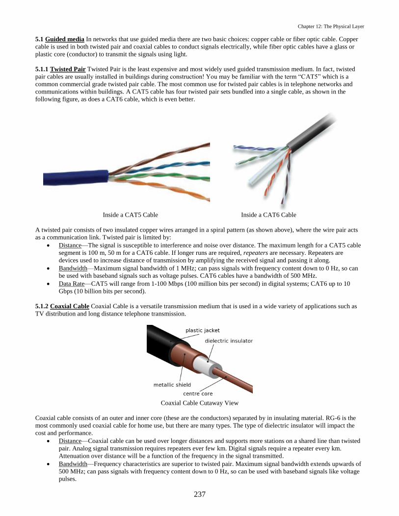
5.1.1 Twisted Pair Twisted Pair is the least expensive and most widely used guided transmission medium. In fact, twisted
pair cables are usually installed in buildings during construction! You may be familiar with the term “CAT5” which is a
common commercial grade twisted pair cable. The most common use for twisted pair cables is in telephone networks and
communications within buildings. A CAT5 cable has four twisted pair sets bundled into a single cable, as shown in the
following figure, as does a CAT6 cable, which is even better.
Inside a CAT5 Cable Inside a CAT6 Cable
A twisted pair consists of two insulated copper wires arranged in a spiral pattern (as shown above), where the wire pair acts
as a communication link. Twisted pair is limited by:
Distance—The signal is susceptible to interference and noise over distance. The maximum length for a CAT5 cable
segment is 100 m, 50 m for a CAT6 cable. If longer runs are required, repeaters are necessary. Repeaters are
devices used to increase distance of transmission by amplifying the received signal and passing it along.
Bandwidth—Maximum signal bandwidth of 1 MHz; can pass signals with frequency content down to 0 Hz, so can
be used with baseband signals such as voltage pulses. CAT6 cables have a bandwidth of 500 MHz.
Data Rate—CAT5 will range from 1-100 Mbps (100 million bits per second) in digital systems; CAT6 up to 10
Gbps (10 billion bits per second).
5.1.2 Coaxial Cable Coaxial Cable is a versatile transmission medium that is used in a wide variety of applications such as
TV distribution and long distance telephone transmission.
Coaxial Cable Cutaway View
Coaxial cable consists of an outer and inner core (these are the conductors) separated by in insulating material. RG-6 is the
most commonly used coaxial cable for home use, but there are many types. The type of dielectric insulator will impact the
cost and performance.
Distance—Coaxial cable can be used over longer distances and supports more stations on a shared line than twisted
pair. Analog signal transmission requires repeaters ever few km. Digital signals require a repeater every km.
Attenuation over distance will be a function of the frequency in the signal transmitted.
Bandwidth—Frequency characteristics are superior to twisted pair. Maximum signal bandwidth extends upwards of
500 MHz; can pass signals with frequency content down to 0 Hz, so can be used with baseband signals like voltage
pulses.

Chapter 12: The Physical Layer
238
Data Rate—Up to 1 Gbps in digital systems. Better performance at higher frequencies.
5.1.3 Optical Fiber Optical fiber is a thin flexible medium capable of guiding an optical (light) ray. Optical fiber’s
performance over distance has made it widely used in long distance communications. Approximately 99 percent of
international data is transmitted over undersea fiber optic cables. At the same time the bandwidth, data rate, and relatively
inexpensive cost has made optical fiber more popular in recent years to deliver high speeds of data to consumers’ doorsteps
(e.g., Verizon Fios).
Optical Fiber Cutaway View
Optical fiber consists of a core of optical fiber, cladding which surrounds the core and provides an index of refraction that
helps to contain the light, and a jacket, which is an insulator. Fiber optic cable is considerably thinner and lighter than copper
based cables.
Distance—Optical fiber has excellent performance over long distances. It allows for greater repeater spacing,
approximately every 80-100 km.
Bandwidth—Fiber optic cable provided to residential consumers (called single-mode fiber), such as Fios, has a
bandwidth of 20 GHz. Some systems have a bandwidth in the THz range. Not suitable for baseband signals; used
only for bandpass communication.
Data Rate—Data rate is dependent upon distance but has rapidly increased in recent years. Single mode fiber optic
cables, which have become popular with in-home providers such as Fios, deliver data rates of 10 Gbps. The Marea
subsea cable (primarily for Microsoft and Facebook customer services) from Virginia Beach, VA to Spain carries a
data rate of 160 Tbps (tera bits per second).6
5.2 Unguided media Air, vacuum, and seawater are all examples of unguided or wireless transmission mediums. There are
many applications for wireless transmission. Wireless transmission is the only feasible method for communicating with an
aircraft, submarine, satellite, cell phone, or even a Marine on the move in the tree line. Generally any application that requires
mobility will use wireless transmission media.
Distance—For unguided media, transmissions and reception of signals is achieved by means of an antenna. The
distance achievable with wireless transmission varies widely with transmission (or carrier) frequency and
transmitted power. The Wireless section of the course covers antennas, modes of propagation and distance
calculations.
Bandwidth—Since unguided media usually refers to the atmosphere, some care must be taken so transmitters don’t
interfere with each other by transmitting in the same band of frequencies. Preventing interference is one of the jobs
of the Federal Communication Commission (FCC). Bandwidth is usually limited by the bandwidth assigned to the
transmitter by the FCC, and can vary greatly depending on the type of communication (i.e., commercial AM or FM
radio, WiFi, cell phone, broadcast television, etc.). Unguided media is not suitable for baseband transmission, so
baseband signals must be modulated (i.e., their frequency content must be upshifted in frequency) to make them
bandpass signals (discussed in more detail in the Wireless section of the course).
Data Rate—The data rate is largely dictated by the modulation used in bandpass communication (discussed in more
detail in the Wireless section of the course).
Practice Problem 12.3
What is line coding?
Solution:
6 https://www.submarinenetworks.com/en/systems/trans-atlantic/marea/microsoft-and-facebook-to-build-marea-cable-across-
atlantic

Chapter 12: The Physical Layer
239
Practice Problem 12.4
What is the main difference between synchronous and asynchronous digital communication?
Solution:
6. Chapter Summary
In this chapter you have learned about how analog and digital signals are handled at the physical layer. In a networked
infrastructure, data (bits) is generated at the application layer, processed and encapsulated at the subsequent layers before
ultimately arriving at the physical layer where actual communication takes place. This is where the data will actually leave
your machine for the first time. We have seen a variety of ways that information may be transmitted as signals through the
physical layer. Depending on the hardware on your computer, there may be multiple communication connections options
available. For example, you have a laptop computer that has both a Wi-Fi card (for wireless connection) and an Ethernet port
(for wired connection) that you can use to communicate with the USNA network. On your computer you have the option of
choosing one method or the other. Other devices, like a cell phone will only communicate with a cell tower via unguided
media. There is no one-size-fits-all approach for transmitting data at the physical layer, but this leaves us with flexibility, not
constraints.

240
THIS PAGE INTENTIONALLY BLANK

Chapter 12: The Physical Layer
241
CH. 12 Problems
1. In your own words describe what the physical layer is responsible for.
2. Why do we need wireless transmissions media?
3. List the factors that are considered when evaluating transmission media.
4. Determine the transmitted voltage waveform that would be present if you push your “]” key (the right square-bracket
key) when you are communicating with another computer via asynchronous serial transmission. Assume that you are
using a start bit and two stop bits. Also assume that:
Normal voltage on the wire is low
A 1-bit is a low voltage pulse; so a 0-bit is high
A start bit is a 0-bit; so a stop bit is a 1-bit
ASCII characters use 7 data bits
5. Determine the ASCII character corresponding to the following o-scope display. Note that the arrow near the left top of
the display points to the start bit. Also assume that:
Normal voltage on the wire is low
A 1-bit is a low voltage pulse; so a 0-bit is high
A start bit is a 0-bit; so a stop bit is a 1-bit
ASCII characters use 8 data bits
6. Determine the ASCII character corresponding to the following o-scope display. Note that the arrow near the left top of
the display points to the start bit. Also assume that:
Normal voltage on the wire is low
A 1-bit is a low voltage pulse; so a 0-bit is high
A start bit is a 0-bit; so a stop bit is a 1-bit
ASCII characters use 8 data bits

242
THIS PAGE INTENTIONALLY LEFT BLANK

Chapter 12: The Physical Layer
243
Security Exercise 12
Asynchronous Serial Digital Baseband Transmission
Discussion: In this chapter, you learned that bits are transmitted over a copper wire as a series of voltage pulses (a process
referred to as line coding). You also learned that there are a number of ways to represent ones and zeros with voltage pulses
(e.g., is a 1-bit represented by a voltage pulse and a 0-bit by no voltage pulse? Or is a 1-bit a positive voltage pulse and a 0-
bit a negative voltage pulse? Does the pulse last for the entire bit? Etc.).
Important takeaways from today’s lecture as they apply to this SX:
Normal voltage on the wire is low
A 1-bit is a low voltage pulse; so a 0-bit is high
ASCII characters are transmitted in 8 data bits
The data bits are transmitted in reverse order, the least significant bit first
To transmit an ASCII character, a start bit is transmitted first, and a stop bit is transmitted last (after the data
bits)
A start bit is a 0-bit; so a start bit is high
A stop bit is a 1-bit; so a stop bit is low
Objective: To familiarize each Midshipman with how ASCII characters are physically represented when transmitted over a
wire. That is, when we transmit an ASCII character, we don’t actually transmit 1s and 0s, but rather voltage waveforms that
represent the 1s and 0s.
Part 1: Hardware Set Up
Since your computer does not have the serial output port we need for this security
exercise, we will use an adapter that plugs into one of your USB ports and will convert
the USB port to the desired type of serial port. An oscilloscope (usually shortened to o-
scope) will be used to display what the signal looks like. Wiring will carry the signal
from your laptop to the o-scope so it can be viewed.
o Carefully plug the serial port adapter into one of your laptop’s USB ports. This
is shown in the photo to the right. The rest of the wiring should already be pre-
staged so you ONLY need to plug in this serial port chip.
o On the o-scope, push the button that says
SAVE/RECALL, then the button on the screen (a soft
button) that says RECALL SETUP, then RECALL
FROM SETUP, then SETUP 10.
o Once you recall Setup 10, your O-scope display should
look similar to the figure to the right, which is annotated
with some useful information relative to the setup.
Hardware set up is now complete. On the following page is an
annotated picture of the O-scope face, annotated with all the
controls that you may use in this SX and in following SXs.

Chapter 12: The Physical Layer
244
Part 2: Tera Term Software Set Up
To set up the communications, we’ll use a program called Tera Term, which works like Telnet that you used back in SY110,
allowing your computer to talk directly to another computer. Today, you won’t be talking to another computer, but you’re
telling Tera Term that you want it to send data to somewhere outside your computer. This way, you’ll see the bits transmitted
when you press a keyboard key using the pins on the output of the serial port chip. To be precise, today you’ll be setting up
and using asynchronous serial data communication.
o Create a folder on your desktop called SX12, then download the file called teraterm-4.95.exe from the U: drive in
the “U:/Cyber2/EC310/SX12 Physical Layer” folder and move it to your SX12 folder.
o Double-click the teraterm-4.95.exe file to install it on your laptop. Accept the license agreement, accept all the
default installation options, and on the final window (“Finish”), check the box labeled “Launch Tera Term” and
click on “Finish”.
o When Tera Term starts up, a dialog box similar to the one shown below will appear.
o The default type of communication is TCP/IP, but choose “Serial” and the communication port used will be the
serial port associated with the serial port chip. Note: if for some reason the “Serial” choice is not available, contact
the instructor or lab tech…you’ll have to install an additional piece of software to make it work.

Chapter 12: The Physical Layer
245
o Click “OK” and you’re ready to communicate using the “Tera Term VT” window shown below. When you click in
this window and then press the keys on your keyboard, you will be transmitting those ASCII characters. The Tera
Term window is now on your desktop, and looks like the following:
o Before communicating, ensure the communication protocol is set up correctly. From the “Setup” dropdown menu,
choose “Serial port…”, and a dialog box similar to the one shown below will appear. All of the parameter values
you see in this dialog box are the ones we will use today. Other than the Port number (your port number may be
different than mine, but that’s okay), these should be the default settings. Other than the Port number, if your
settings don’t match the figure below, change it to the following selections.
o These settings define the protocol we will be using, and are described as:
o Port—Which port number your computer is using for this serial communication.
o Baud rate—How fast symbols (voltage pulses that represent 1s and 0s) are transmitted, in symbols/sec. In
our case, each symbol (voltage pulse) represents a bit, so the bit rate in bits/sec is equal to the baud rate.
o Data—The number of bits of data transmitted in each burst.
o Parity—Used for error detection. An extra bit could be sent to help the receiver determine if a bit has been
received in error. We will not be using parity.
o Stop—The number of stop bits we will use. This could be 1, 1.5 or 2. Note that 1.5 stop bits is basically a
stop bit that lasts a bit and a half in duration.
o Flow control—This helps control the flow of data if the one computer is not as fast as the other.
o Transmit delay—If needed, there will be a delay in between transmissions.
o Click on “OK.
o Finally, set up a local echo of the keys you type. From the “Setup” dropdown menu, choose “Terminal…” and check
the box labeled “Local echo” as shown below, then “OK”. This will allow you to see the keys you type in the Tera
Term VT window.

Chapter 12: The Physical Layer
246
We are now ready to begin communicating!
Part 3: Asynchronous Serial Digital Baseband Transmission
How many bits do you expect to see on the o-scope when you press a key on your keyboard? Let’s look closely at what was
displayed on the picture of the o-scope face shown earlier.
o Push the SINGLE SEQ button on the O-scope, then in the Tera Term window press the lowercase “m” key.
The following figure shows what you should see on the o-scope when you press the “m” key (lower-case m). It is important
to get a sense for how wide a single bit is (that is, how much time it takes to transmit one bit) so you can look at consecutive
ones or zeros and tell how many there are. The figure is annotated to describe what is seen and how to take that and
determine which ASCII character has been sent.
We count 8 bits for the ASCII character, one START bit, and we’re using one STOP bit, so transmitting a single key on the
keyboard corresponds to 8+1+1 = 10 bits. We don’t actually see the STOP bit, because it is a 1-bit (low), and the voltage on
the wire is normally low…but it is there. It would be apparent had transmitted more than one character in the same
transmission (more on this later).
Since we want to compare what was seen on the o-scope to what we seen in an ASCII table, open a browser and refer to the
ASCII table at:

Chapter 12: The Physical Layer
247
https://www.sciencebuddies.org/science-fair-projects/project_ideas/CompSci_ASCII_Table.shtml
This table conveniently shows the 8-bit representation for ASCII characters (as bits, not hex values) that you’ll need to
answer questions in this security exercise.
NOTE: When no transmission occurs, voltage is low, and only goes high when the start bit appears. Also, if you look up “m”
in the ASCII table, you’d see (in binary) 0110 1101, which seems to be the reverse of what is transmitted! It looks like bits
are sent in something like a “little-endian” format! This means that after determining what the data bits are, they must be
reversed to match what is in the ASCII table.
ALSO NOTE: Comparing the display above and the ASCII table, you can also see that for this communication link, START
bits are 0-bits, so a 0-bit is high voltage, and a 1-bit is low voltage. This is but one way to represent transmitted 1s and 0s
with voltage pulses.
IMPORTANT: In between transmissions, push the SINGLE SEQ button on the O-scope so that the O-scope is ready
to trigger on the next character.
o Push the SINGLE SEQ button on the O-scope so that the O-scope is ready to trigger on (capture) the next
keystroke, then type the u (lower case u) character. The voltage signal representing the character that you typed in
the Tera Term window should now appear on the o-scope (after you properly made all the adjustments above). How
many bits do you see?
Question 1: For the u character, draw a rough sketch of the waveform you transmitted on your answer sheet, and specify the
corresponding bits you believe them to be (1s or 0s). Indicate which bits are data bits and which are start/stop bits.
Question 2: Compare the bits you’ve seen on the O-scope with the ASCII table from the website pointed out earlier in this
security exercise, and determine if they match. Do they match?
o Push the SINGLE SEQ button on the o-scope, then press the U (uppercase U) character.
Question 3: For the U character, draw a rough sketch of the waveform you transmitted on your answer sheet, and specify the
corresponding bits you believe them to be (1s or 0s). Indicate which bits are data bits and which are start/stop bits. Again,
compare the bits you see to the ASCII table to ensure they match. If they don’t, contact the lab tech or instructor.
o Push the SINGLE SEQ button on the o-scope, then press the ~ (tilde) character.
Question 4: For the ~ character, draw a rough sketch of the waveform you transmitted on your answer sheet, and specify the
corresponding bits you believe them to be (1s or 0s). Which bits are data bits and which are start/stop bits? And for the last
time: compare the bits you see to the ASCII table to ensure they match. If they don’t, contact the lab tech or instructor.
Question 5: The horizontal axis (time) should be set to 250 μsec/div (microseconds), that is, each of the blocks on the display
is 250 μsec wide. For the ~ (tilde) character waveform which should still be on the o-scope, estimate what the duration of one
bit is for this transmission (that is, how wide in seconds is one bit)?
Question 6: Your answer to Question 5 is how long a bit lasts in seconds. Bit rate is how many bits per second (bps) are
being transmitted. Calculate the bit rate for this transmission using your answer to Question 5. What should the bit rate be
(that is, what did the settings for the serial connection in Tera Term say it should be)?
o Now let’s transmit a small text file. Download the file called “Us.txt” from the U: drive and move it to your SX12
folder.
o In order to be able to see all the bits, using the HORIZONTAL POSITION knob, move the small arrow on the top
of the display in the left direction so that it is close to the left edge of the screen (this adjusts time = 0 to close to the
left edge of the display).
o Push the SINGLE SEQ button on the o-scope
o In the Tera Term window, choose “Send file” from the dropdown menu, and navigate to your SX12 folder and
choose “Us.txt”.
Question 7: For sending this file, how many bits were transmitted? Write out the stream of bits transmitted, including start
and stop bits. In your stream of bits indicate the ASCII characters.
Question 8: What type of line coding is used in this SX?

Chapter 12: The Physical Layer
248
Question 9 (bonus): Using ONLY the transmitted voltage pulses in the screen capture shown in the figure below, determine
the ASCII character(s) that have been transmitted.

Chapter 12: The Physical Layer
249
Security Exercise 12 Answer Sheet
Name:
Question 1: Character ‘u’ (lowercase u)
Question 2:
Question 3: Character ‘U’ (uppercase U)
Question 4: Character ~ (tilde)
Question 5:
Question 6:
Question 7:
Question 8:
Question 9 (bonus): What is (are) the ASCII character(s)?

250
THIS PAGE INTENTIONALLY LEFT BLANK

Chapter 13: Data Link Layer, LAN’s and Ethernet
Objectives:
(a) Define the structure of an Ethernet address.
(b) State the minimum and maximum size of an Ethernet frame.
(c) Calculate the bandwidth available to users in various network configurations.
(d) Distinguish between the capabilities and uses of a hub, a bridge and a switch.
1. Introduction
To refresh our memory, from Chapter 11 we learned that the Data Link Layer is concerned with transferring data across a
single link connecting two nodes. The Protocol Data Unit (PDU) at the Data Link Layer is termed a “frame.”
The roles and responsibilities assigned to the data link layer include:
1. Setting Frame Boundaries
2. Error Control
3. Link Flow Control
4. Control access to shared channels – or the Multiple Access Problem.
Any protocol employed at the data link layer must address each of these tasks. It may surprise you to know that over time
there have been many different data link layer protocols. However, alternatives have lost their promise and there are two
different Data Link Layer protocols which are dominant. One which is suited for wired connections, IEEE 802.3 known as
“Ethernet” and one which is suited for wireless connections IEEE 802.11, known as “Wi-Fi.” Both accomplish the four roles
and responsibilities above but handle the particulars differently. To better understand the functions that are performed at the
Data Link Layer, we will examine how the Ethernet protocol addresses them in this chapter.
2. Local Area Network (LAN) Overview
A LAN consists of a collection of devices which have a shared transmission medium and must share the network’s
transmission capacity. In the late 1960's and into the early 1970's, computers were stand-alone devices. A computer at, say,
Stanford, had no way of communicating with a computer at, say, the Naval Academy. Research teams (largely funded by the
DoD) began to explore methods for linking computers together, allowing them to transmit information back and forth, this
exploration gave rise to what we know today as a LAN.
A breakthrough occurred when Robert Metcalfe proposed a technique for joining computers together which he called
Ethernet. At heart, the computers were joined together by a wire allowing bits to flow between computers. The sketch below
(from Metcalfe's 1976 conference paper) shows four computers (in red) joined together by a wire (in yellow). (Note that one
of the four computers is drawn to be larger than the other three in order to show some internal details).
3. Ethernet
The four data link layer roles and responsibilities can be rephrased as four issues. Metcalfe's breakthrough proposal—
Ethernet—handles these four issues.

Chapter 13: Data Link Layer, LAN’s and Ethernet
252
First, if one computer sends data to another, there has to be a mechanism to allow the intended recipient to know
where the block of data begins and ends. In other words, the recipient must be able to look at the collection of
received bits—called a frame—and determine where the frame begins and ends. This is called the framing problem.
Second, in order to send a frame to a specific device, every device will need a unique address. This is the address
problem.
Third, the receiver should be able to determine if the received frame has errors. This is called the error-control
problem.
Fourth, we have to consider the possibility that more than one computer may place their frame on the wire at the
same time. This will cause the electrical signals to collide, and both frames will be destroyed. This is called the
multiple access problem.
Other competing proposals to join computers together into a local area network (Token Ring, Token Bus, ATM, FDDI) have
since fizzled and died, leaving Ethernet as the only game in town for wired local area networks.
The original Ethernet transmitted at a bit rate of 10 mega-bits per second (Mbps), also known as Standard Ethernet. In 1995,
a 100 Mbps Ethernet standard was introduced, dubbed Fast Ethernet. This was followed in 1998 by Gigabit Ethernet (with a
data rate of 1 Gbps) and in 2002 by a 10 Gbps standard (10-Gigabit Ethernet). A 100 Gbps Ethernet standard was approved
in 2010.
Note that we are dealing exclusively with transmitting data over a single link. Stated another way and with reference to the
TCP/IP reference model: we are dealing with data link-layer roles. Additionally, note that Ethernet is implemented in a
computer's Network Interface Card (NIC).
3.1 The Framing Problem All Ethernet variants (10 Mbps, 100 Mbps, 1 Gbps and 10 Gbps) use the same data link frame
format, shown below.
Ethernet Frame
The Data Link layer frame is then organized into the Physical layer as shown below.
Organization of Physical and Data Link layer.
The fields for the diagrams above are described below:
Preamble: The preamble is not formally part of the Ethernet frame. It is added by the physical layer. It consists of
the byte 10101010 repeated 7 times (56 bits of alternating 1s and 0s). The preamble allows the receiver to
synchronize to the beginning of the frame.
Start Frame Delimiter (SFD): The SFD is not formally part of the Ethernet frame. It is added by the physical layer.
It is the single byte: 10101011 Notice that the start frame delimiter follows the same pattern of alternating ones
and zeroes as the preamble, except that it concludes with two consecutive 1's. These two consecutive 1's indicate
that synchronization is over, and the real stuff is about to start: the next item will be the destination address.
The Destination and the Source Ethernet Addresses: Much more on this to follow!
Length or Type: This field usually specifies the kind of data the frame carries (e.g.: Is the data an IP packet?). In
rare implementations, this field is used instead to serve as a Length Field, providing the number of bytes in the data
field.

Chapter 13: Data Link Layer, LAN’s and Ethernet
253
Data and padding: This holds the data that was received from the network layer. The minimum size of the "Data
and Padding" field must be 46 bytes, and the maximum size of this field is 1500 bytes.
CRC: Cyclic Redundancy Code used for error detection. More on this below.
Practice Problem 13.1
What is the minimum size of an Ethernet frame? (Do not include the physical layer header in your calculation.)
Solution:
Practice Problem 13.2
What is the maximum size of an Ethernet frame? (Do not include the physical layer header in your calculation.)
Solution:
Practice Problem 13.3
Why would padding ever be used in the field marked Data and padding?
Solution:
So, Ethernet frames must be at least 64 bytes and are not permitted to exceed 1518 bytes. Which raises the question: Why
these size limitations?
The maximum Ethernet frame size is easy to appreciate. We limit the maximum frame to 1518 bytes for three reasons:
To prevent a single user from hogging the network Recall the picture on page 251 that shows four users sending
their data over the same wire. Suppose you are one of those users, and you want to send a frame. With Ethernet, a
user who wants to transmit a frame first listens on the wire to make sure no one else is already transmitting. If
someone else is already transmitting, then it would make no sense for you to transmit at the same time: You would
garble the transmission in progress, and your transmission would also garble. So, you patiently wait for the wire to
go idle before you transmit. Since Ethernet users always politely wait for the shared wire to go idle before
transmitting, a greedy user who starts transmitting could keep transmitting forever, never allowing others an
opportunity to transmit their frames. To avoid this, a user is allowed to transmit at most 1518 bytes before they must
stop and give other users an opportunity to transmit their frames.
Error control With Ethernet, if a single bit arrives in error, the entire frame is thrown away by the receiver. Since
each bit represents an opportunity for error, the fewer bits we have, the fewer opportunities for error we have.
Historical reasons Data that arrives at the NIC must be buffered before it is sent to main memory. Although memory
is very cheap today, memory was very expensive in the 1970s and 1980s when the Ethernet standard was developed.
The minimum Ethernet frame size—64 bytes—is based on technical considerations that are far less intuitive. We mentioned
that when a host using Ethernet wants to transmit a frame, it first listens to see if anyone else is transmitting. Only if a host
senses that the medium is "quiet" does it proceed with the transmission of its frame.
But even if a host takes care to ensure that the medium is quiet, collisions can still occur! For example, suppose two hosts
want to transmit an Ethernet frame at the same time and both first listen to ensure the medium is not in use. Both stations will
detect that the medium is not in use and both will start transmitting! These sorts of collisions are unavoidable.
Since collisions are unavoidable, we want to ensure that a user can tell if its transmission was involved in a collision. When
Ethernet hosts start transmitting, they continue to listen to the channel to detect a collision. It is important for a host to know
if its frame was involved in a collision since any frames involved in collisions will need to be retransmitted. Thus, we need to
ensure that User-1 is still transmitting under the condition that the furthest away station (say, User-2) listens to the channel
just before User-1's frame arrives, senses it idle and starts transmitting also.

Chapter 13: Data Link Layer, LAN’s and Ethernet
254
Based on the maximum allowed separation between users and the speed of light (more precisely: the speed of propagation in
the cable), it can be shown (we skip the derivation) that if the minimum frame size is set to 64 bytes (512 bits) a host will be
able to tell if it was its frame that was involved in a collision.
3.2 The Address Problem Each Network Interface Card (NIC) is assigned a globally unique address—an Ethernet address—
that is burned into the card's Read Only Memory (ROM). ROM is non-volatile memory whose contents cannot be altered by
the user. All machines on an Ethernet LAN7 are guaranteed to have unique addresses. Moreover, no two hosts anywhere in the
world have the same Ethernet address.
So, when you buy a NIC (or, as is most often the case, a computer that contains a NIC), you are also buying a globally unique
Ethernet address that only you possess.
Ethernet Addresses are 6 bytes. It is important to realize that Ethernet addresses are also commonly referred to as physical
addresses, hardware addresses and Medium Access Control (MAC) addresses—these terms are all synonyms!
Practice Problem 13.4
(a) How many bits are in an Ethernet address?
(b) How many hexadecimal digits are needed to express an Ethernet address?
Solution: (a) (b)
Ethernet addresses are usually expressed in hexadecimal notation (sometimes with colons between the bytes). For example,
an Ethernet address might be 06:01:03:02:2A:3D.
Practice Problem 13.5
Two of these 48 bits in an Ethernet address are used for special purposes. Disregarding these two bits, how many possible
Ethernet addresses exist?
Solution:
Practice Problem 13.6
If there are 7 billion people in the world, and we disperse Ethernet addresses uniformly, how many addresses are available for
each person?
Solution:
You should be convinced that we are in no danger of "running out" of Ethernet addresses!
The uniqueness of Ethernet addresses is assured by the fact that the first 3 bytes of the address are assigned to a given
manufacturer (or vendor), and this vendor must use these three bytes as the first three bytes in every NIC that the vendor
manufactures. (The Institute of Electrical and Electronics Engineers—IEEE—is the group that actually does this assignment).
For instance, all NICs manufactured by 3COM have Ethernet addresses starting with 02608C, all NICs manufactured by Cisco
have Ethernet addresses starting with 00000C, etc.
Practice Problem 13.7
How many possible Ethernet addresses exist for each individual vendor?
Solution:
Sometimes, a host may want to transmit a frame to every other user on the Ethernet LAN. A special address is reserved for
this purpose. A host may send a frame to everyone by sending the frame to the broadcast address, which is the address
consisting of all ones; i.e., a string of 48 consecutive 1’s.
7 A Local a local area network (LAN) is a network of computers and other associated devices connected on a common
communications link (i.e. cable, wireless) spanning over a relatively small area such as a room, building, or campus. LANs
are capable of transmitting data at very fast rates within a limited distance.

Chapter 13: Data Link Layer, LAN’s and Ethernet
255
Practice Problem 13.8
Express the Ethernet broadcast address in hexadecimal.
Solution:
Referring back to the Ethernet frame image, any frame transmitted by any user arrives at the NIC of all other directly
connected users! Stated another way, the NIC receives all frames that are sent on the wire. But it only forwards some of the
frames up to the host's network layer.
Specifically, the NIC only forwards to the network layer:
Frames addressed to its own unique address. When a frame arrives at the NIC, the NIC checks the frame to see the
destination address. If the destination address of the frame matches its NIC address, then the NIC “realizes” that this
data is intended for itself, and passes the frame to the network layer. If the destination address in the frame does not
match its NIC address, the frame is discarded.
Frames addressed to the broadcast As mentioned, a frame sent to the broadcast address (48 ones) will be accepted by
every NIC.
All frames if the NIC is placed in "promiscuous" mode. A vulnerability of Ethernet is the ease with which an
Ethernet card can be programmed to accept all frames, even frames addressed to other users. So, any user who sets
their NIC to promiscuous mode can examine the traffic sent by all other users.
3.3 The Error Control Problem Recall from the picture of the Ethernet frame shown on the second page of this chapter that
the last four bytes are used for the Cyclic Redundancy Code (CRC). The CRC is used for error detection. Ethernet can only
detect errors; it cannot correct errors. If a frame arrives with errors, it is simply discarded. (Higher-layer protocols may later
recognize the loss of data and take action to remedy the problem, such as by requesting retransmission. Ethernet, though, simply
discards frames containing errors without giving the matter a second thought.)
Ethernet's CRC algorithm hinges on a special number that mathematicians have devised. This number, given the name CRC-
32, is special because it almost never divides evenly into other numbers, i.e., it almost always leaves a remainder when it is
divided into another number. When the NIC crafts a frame to transmit, it fills the four byte CRC field with the specific bits that
will make the total frame (including the CRC field) perfectly divisible (with no remainder) by CRC-32.
When this frame is received by the destination, the destination NIC divides the received frame by CRC-32. If the frame arrives
without errors, the result of the division will be zero and the frame will be accepted. If any bits were flipped en-route from
source to destination the resulting division will leave a remainder and the frame will be discarded.
3.4 The Multiple Access Problem Ethernet hosts share access to a channel. For that reason, Ethernet is termed a Multiple
Access (MA) scheme. Since there are multiple hosts sharing a medium Ethernet hosts listen to (i.e., sense) the channel before
transmitting. This way they do not start transmitting their frame while another frame transmission from some other host is
already in progress. For that reason, Ethernet is termed a Channel Sense Multiple Access (CSMA) scheme.8 Even after an
Ethernet host starts transmitting, it continues to sense the channel for collisions. Collisions can occur if two hosts sense the
channel idle at the same time and start transmitting. When a host detects that its frame is colliding, it immediately stops
transmitting (what's the point of continuing to transmit a frame if we already know it's garbled?). For this reason, Ethernet is
termed a Channel Sense Multiple Access with Collision Detection (CSMA/CD) scheme.
The shared channel is also known as a collision domain. If users have the ability to collide with each other, they are in the same
collision domain.
Suppose we have 4 users on a 10 Mbps Ethernet. The 4 users share the 10 Mbps capacity of the network. If all 4 users have a
lot to say, then each user will, on average, get to use the network ¼ of the time. As a rough approximation, we can say that
each of the 4 users will get to send at 2.5 Mbps. From each user’s perspective, they are on a 2.5 Mbps network, not a 10 Mbps
network.
Make sure you are clear on why things work this way: In Ethernet, users might share a medium, and any user’s transmission
will prevent all others on that same shared medium from transmitting. When one of the four users in our scenario above transmit,
8 Since a signal in this context is carrying our data, it is referred to as a carrier signal, when we sense the channel we are
sensing to detect the presence or absence of the carrier signal. Thus, CSMA is most often called Carrier Sense Multiple Access.

Chapter 13: Data Link Layer, LAN’s and Ethernet
256
the other three users will be prevented from transmitting because they will first sense the channel and will not intentionally
collide with another user.
As a back-of-the-envelope calculation, we can say that the bandwidth 9 available to a user is given by:
Total BW available in the collision domainBW per user =
Number of users sharing the collision domain
It’s interesting to note that this is an “apparent” bandwidth. As a user in the example above you will feel like you are getting
a quarter of the total bandwidth available all of the time. In actuality you are “taking turns” with the other users. When it’s
your turn you get all the bandwidth, when it’s not your turn you get nothing. The turn taking happens very quickly, so it is
not obvious to a user. But this is more like taking turns at the water fountain than splitting a pizza with friends and getting an
increasingly smaller share when there are more friends.
Practice Problem 13.9
What is the bandwidth available to each of the users on the 10 Mbps Ethernet shown below?
13.25
Figure 13.15 A network with and without a bridge
Solution:
Practice Problem 13.10
What is the bandwidth available to each of the users on the 10 Mbps Ethernet shown below?
Solution:
4. Connecting Users on an Ethernet LAN
Ethernet first used a bus topology with heavy garden-hose size coaxial cable. In a bus topology, all users are connected in a
straight-line configuration, as in the example on the prior page. Later, the communication medium transitioned to unshielded
twisted pair (UTP), which was ubiquitous in most office buildings. There has been a proliferation of the types of devices for
interconnecting LANs
9 In networking, the term bandwidth has two meanings. One meaning of bandwidth is data rate, measured in bits per second.
That is the meaning which we use in this chapter. Later in this course (in the Wireless Module) we will encounter the other
meaning of the term bandwidth.

Chapter 13: Data Link Layer, LAN’s and Ethernet
257
4.1. Hubs A hub is the central element in a “star” or “spoke” network topology. While the Ethernet first used a bus topology,
consider that most office buildings were already set up such that telephone lines ran from a central switching cabinet to
individual desks. Similarly UTP wires could run to individual machines and all terminate in a central electrical cabinet that
served as a hub. Here, the term hub was simply meant as a “center of activity,” the way the term is still used as in “Denver is
a hub for United Airlines.” The picture that follows illustrates this idea.
1.13
Figure 1.10 An isolated LAN connecting 12 computers to a hub in a closet
From, Forouzan, Data Communications and Networking, McGraw Hill, 2007
An Ethernet hub from NETGEAR.
Now, devices called Ethernet hubs are used to connect the twisted pairs from each host together. Using the hub pictured
above, we can connect four hosts together simply by plugging each host's NIC into one of the hub's four ports.
When using a hub, we can consider the hosts to be, for practical purposes, electrically soldered together at the hub. When a
single station transmits, the signal that arrives at one port are sent out on all other ports. A frame arriving on one port is not
buffered or stored—it is simply transmitted out on all of the other ports. Fault isolation is easy with hubs—we merely have to
unplug the problem host. Adding and removing hosts is also easy—we just plug in new users and unplug hosts that we want
to remove from the LAN.
It is important to note that a hub is a physical layer device. It only recognizes the existence of bits. When bits arrive on one
port, they are sent out on all of the remaining ports. A hub does not understand that some bits that arrive are Ethernet
addresses and some bits that arrive are CRC, and so forth. To a hub, everything is just bits.
Practice Problem 13.11
Consider the 10 Mbps Ethernet shared by the busy users in the network below. The network uses three 4-port hubs. How
much bandwidth is available to each user?
Solution:

Chapter 13: Data Link Layer, LAN’s and Ethernet
258
4.2 Bridges A bridge is a device designed for use between LANS’s. A bridge is similar to a hub in that it can be used to
connect multiple hosts or multiple LANs. A bridge can be used to connect two or more Ethernet LANs like a hub, but—
unlike a hub—a bridge can divide up the hosts into separate collision domains. When a frame arrives, the bridge looks at the
source and destination Ethernet addresses. The bridge then decides whether the frame should be forwarded (and if so, to
which outgoing port). Since a bridge looks at and understands data link addresses, it operates at the data link layer (Layer 2).
In virtually all cases, there is a need to expand beyond the confines of a single LAN. Why not have a single much larger
LAN? There are several advantages to connecting multiple LANS together. The main advantage of utilizing bridges over
hubs is improved performance. We may want to split a single heavily loaded LAN into separate LANs to improve
performance by limiting collisions and forwarding only when we have to. Bridges have a few ancillary advantages. Bridges
enhance reliability, since a single bad user (outputting continuously) will not disable all hosts; if bridges are used, the bad
user will only kill its segment. Additionally, bridges can be used to enhance security, since we can isolate portions of the
network and only forward frames where they must go.
To make this distinction clear, consider the picture below, which shows two Ethernet LANs joined together by a bridge.
13.25
Figure 13.15 A network with and without a bridge
1 2 3 4 5 6 9 10 11 12 13 14
Suppose Host 3 wants to send a frame to Host 5. Host 3 sends the frame out on the left LAN and it arrives at all users on that
LAN, including the bridge. The bridge will inspect the frame, and see that it is destined for Host 5. The bridge knows that
Host 5 is on the left LAN and must have already received the frame (since everyone on the left LAN received the frame). The
important point: the bridge will not forward the frame to the right-side LAN since the bridge knows that Host 5 is not on the
right-side LAN.
Practice Problem 13.12
Consider users employing 10 Mbps Ethernet. How much bandwidth does each user get in each of the three scenarios below.
(a) Scenario 1:
13.25
Figure 13.15 A network with and without a bridge
(b) Scenario 2:
13.25
Figure 13.15 A network with and without a bridge
(c) Scenario 3:
Solution:
(a) (c)
(b)

Chapter 13: Data Link Layer, LAN’s and Ethernet
259
We should note that the results of the preceding calculations are, at best, approximations. We are presuming that a bridge port
provides as much traffic on a LAN as a typical user. For example, in the picture above, consider the top-left collision domain.
This collision domain has three users, plus the bridge port. The bridge port, however, is conveying the traffic from nine other
users (the users on the other three LANs), so it may not be the case that the bridge port contributes the same amount of traffic
in this collision domain as the other three users. Nevertheless, since bridges are often used to separate users who do not
communicate very often, assuming a bridge port acts as a typical user often yields satisfactory results.
4.3 Switched Ethernet Look at Scenario 3 above, which shows 12 users on a 4-port bridge. In this case the 12 users are
divided into four collision domains, with three users (and a bridge port) within each collision domain.
What would happen if we had the 12 users on a 12-port bridge? In this case each user would be in its own collision domain
(sharing it only with the bridge).
An N-port bridge that serves a number of hosts N is referred to as a “Layer-2 switch" or an "L-2 switch”.
Consider the scenario depicted below, which shows 7 users connected to a 9-port bridge. From here on out, whenever the
number of users is less than or equal to the number of ports (as is the case here), we will use the term Layer-2 switch, or
simply switch, instead of the term bridge.
Do collisions still occur? The answer is Yes, but only between a user and the switch. In the scenario above, all hosts can
successfully transmit at the same time since each port is now a separate collision domain.
Note that L-2 switches, like bridges, look at frame addresses, and operate at the data link layer. While many people use the
two terms interchangeably, a switch is most often used to connect individual computers, whereas bridges usually connect
LANs. Thus, in this taxonomy, with L-2 switches each computer is in its own collision domain, whereas with bridges each
connected LAN forms a collision domain.
Practice Problem 13.13
You have set up an Ethernet LAN for 10 users. For simplicity, assume the network has an efficiency of 100% and that
resources are shared equally among users. How much bandwidth is available to each user if:
(a) The 10 users are connected on a 10 Mbps Ethernet to a hub
(b) The 10 users are connected on a 10 Mbps switched Ethernet
Solution:
(a)
(b)
Practice Problem 13.14
You want to set up an Ethernet LAN for a group of 10 offices at the Pentagon. Each office requires 2 digital telephone lines
(64 kbps each). Additionally, each office must support a peak web browsing demand of 40,000 bytes/min.
(a) What is the total bit rate demand of the LAN?
(b) Would a standard 10 Mbps Ethernet suffice?
Solution:
(a)
(b)

Chapter 13: Data Link Layer, LAN’s and Ethernet
260
Practice Problem 13.15
Match the column on the left with the description on the right:
Network Interface Card (a) Looks at MAC address and then forwards the frame on the correct port
Hub (b) Copies incoming bits to all other ports
Switch (c) Piece of equipment with a unique address that translates bits to signals and
transmits the signals on the medium.
Practice Problem 13.16
If an entire IP packet has 8096 bytes, how many Ethernet frames are required to transmit this packet?
Solution:
Practice Problem 13.17
Answer True or False to the following statements:
(a) An Ethernet address is normally expressed in decimal.
(b) An Ethernet address is burned into hardware and never changes
(c) An Ethernet address is used at the network layer to address packets.
(d) An Ethernet address, MAC address, and Hardware address are all the same thing.
(e) When I log on to different networks my Ethernet Address can change every time.
5. Technological Innovations
In the years since Ethernet’s introduction there have major technological innovations that seek to enhance performance,
increase network spends and more. Here are three examples which have sought to build off of existing standards and
infrastructure vice reinventing the wheel.
5.1 Fast Ethernet (1995) Fast Ethernet uses the same frame format as “standard Ethernet.” Fast Ethernet is backward-
compatible with standard Ethernet. And, perhaps surprisingly, it uses the same minimum and maximum frame lengths as
standard Ethernet. Also, it has the same maximum physical length as standard Ethernet (100 meters for UTP). There is a big
difference: Fast Ethernet operates at 100 Mbps. How do we raise the data rate? The details are rather technical, and have to
do with the improvements in technology over the years. The original Ethernet operates at 10 Mbps, but required a special
type of signaling called Manchester encoding. Advances in transmission media allowed for a signaling scheme that supported
higher data rates. Better clock circuitry allowed us to raise the transmission speed without worrying about loss of
synchronization. Instead of using one twisted pair, we use four twisted pairs: 1 to the switch, 1 from the switch, and 2 that are
switchable to support the current direction of traffic flow.
TWISTED PAIR 1:Always to the network
TWISTED PAIR 2:Always from the network
TWISTED PAIR 3 and TWISTED PAIR 4
Can be switched from one direction to the other, to
support the current desired direction of traffic flow
Finally, 3-level signaling is used at the physical layer. Instead of sending a 0 or 1, we can send 0, -1 or +1.
5.2 Switches We can consider a switch a technological innovation. A hub, often in a building wiring closet is the center of
activity with a line to each individual host. With that infrastructure already in place replacing the hub with a switch is both

Chapter 13: Data Link Layer, LAN’s and Ethernet
261
easy and efficient as the switch would dramatically boost our performance and apparent bandwidth moving each user onto
their own collision domain. In fact since the advent of Layer 2 switches bridge sales have suffered commercially!
5.3 Wireless Local Area Networks Mentioned briefly at the start of the chapter, many of these principals can be applied to
Wireless Local Area Networks. A different data link layer protocol is employed, 802.11 (Wi-Fi) instead of Ethernet. A
different frame size, error control and multiple access solution are necessary to address the challenges of the wireless
environment but the addressing solution is the same. It is common for the three devices we discussed- hubs, bridges, and
switches- to support a wireless LAN and connect to other wired LANs so that the networks we interact with can be thought of
as hybrid. Think of the Naval Academy. Bancroft Hall was extensively wired to support Ethernet when “the internet came to
the hall.” There is no reason to migrate to Wi-fi in the hall, however when Midshipman began being issued laptops there was
the option decide how they would connect in the classroom. With new students passing through every period, the desire for
portability and other factors led to implementing Wi-fi in the Classrooms vice Ethernet. (Although your instructor’s
workstation connects via Ethernet as it previously had!)

Chapter 13: Data Link Layer, LAN’s and Ethernet
262
THIS PAGE INTENTIONALLY LEFT BLANK

Chapter 13: Data Link Layer, LAN’s and Ethernet
263
CH. 13 Problems
1. What are the advantages of dividing an Ethernet LAN with a bridge?
2. What is the relationship between a switch and a bridge?
3. Suppose the Ethernet data link layer receives 48 bytes of data from the network layer. How many bytes of padding must
be added to the data?
4. For the smallest Ethernet frame, what is the ratio of useful data to the total data in the frame?
5. Sketch the Ethernet frame required to send the text string “Hello World” from Alice (whose MAC address is
11:22:33:44:55:66) to Bob (whose MAC address is AA:BB:CC:DD:EE:FF). Assume that any padding bytes
consist of all-zeroes, and that the Length/Type field is used as a Length field. RECALL: ALL VALUES ARE
REPRESENTED IN HEXADECIMAL!
Your error correction bits are 0101 1100 1010 1010 1111 1110 1011 1101.
6. Consider the network below, which shows four 10 Mbps LANs connected by two bridges, labeled B1 and B2. Assume
all users (labeled 1 through 7) are very chatty and equally chatty.
LAN 4
B 1 B 2
LAN 1 LAN 2 LAN 3
(a) What is the effective data rate seen by user 4?
(b) What is the effective data rate seen by user 5?
(c) What is the effective data rate seen by user 6?
(d) What is the effective data rate seen by user 6 if the two bridges are replaced with hubs?
7. Two standard (10 Mbps) Ethernet topologies are illustrated in Figure 1 and Figure 2 for a network consisting of six
computers
Figure 1
Figure 2
(a) How much bandwidth does each user get for the network topology depicted in Figure 1?
(b) How much bandwidth does each user get for the network topology depicted in Figure 2?
6 7
1 2 3 4 5

264
THIS PAGE INTENTIONALLY LEFT BLANK

Chapter 13: Data Link Layer, LAN’s and Ethernet
265
Security Exercise 13
Part 1: Your Ethernet Address
A computer is connected to a network by a Network Interface Card (NIC), also termed a network adapter. That is, the NIC is
the physical interface between a computer and the networking medium. The networking medium, in turn, might be a wire, a
fiber optic strand, or free space (in the case of wireless networks).
Each NIC is assigned a globally unique address burned into the card's Read Only Memory. All machines on an Ethernet
LAN are guaranteed to have unique addresses. No two Ethernet users anywhere in the world can have the same global
address. Addresses are 6 bytes, of which 46 bits are used for the unique address.
The NIC interfaces with the physical media, so this globally-unique address is often called the physical address. Since
physical devices are often termed hardware, a NIC’s unique address is also frequently referred to as a hardware address.
Finally, since the NIC controls access between the computer and the networking media, its address is also termed a Media
Access Control (MAC) address. Since most NICs conform to the Ethernet standard, the NIC address is also called an
Ethernet address. Thus, the NIC address goes by four different names which are often used interchangeably:
Physical Address
Hardware Address
MAC Address
Ethernet address
In Windows, not in the VM, open a command prompt. (To open a command click the Start button and in the search box type
cmd and press Enter.)
At the command prompt, type: getmac /v
Question 1: Ignoring VMware virtual adapters, and Wi-Fi, what is your computers' Ethernet address (aka Local Area
Connection or physical address)?
Recall that a MAC address is 48-bits. The first 3 bytes provide the address of the NIC manufacturer (or vendor). The Institute
of Electrical and Electronics Engineers (IEEE) assigns blocks of addresses to various manufacturers. For a listing of vendor
codes, see
http://standards.ieee.org/develop/regauth/oui/oui.txt
(Note: This is a long text file and may take long to download. A copy is provided on the course website under Resources.)
Question 2: What vendor manufactured your Ethernet card?
Question 3: Ward Hall has a policy that midshipmen can only connect their original issued computers to the USNA network.
Suppose you go to Best Buy, but a new computer and connect it to the network. Will Ward Hall be able to tell? If so, how?
Can you "spoof" your MAC address—i.e., have your computer tell the rest of the world your MAC address is different from
the actual value burned into ROM? The answer is: Yes, it is very easy to spoof your MAC address—it requires a change to
one line of the easy-to-edit Windows registry. However, you should not do this since even a small screw-up while editing the
Windows registry can irreparably damage your computer. Bottom line, unless you are a CS major with a 4.0 QPR and ten
computers (so you have a few to spare), you should never edit the Windows registry.
Part 2: Using ping to Determine the Largest Possible Ethernet Frame Size
ping is a tool that can be used to determine whether our computer can reach another computer across the Internet. From the
Windows command prompt, type:
ping www.cnn.com
You should see something similar to:
C:> ping www.cnn.com
Pinging turner.map.fastly.net [151.101.32.73] with 32 bytes of data:
Reply from 151.101.32.73: bytes=32 time=4ms TTL=49
Reply from 151.101.32.73: bytes=32 time=4ms TTL=49

Chapter 13: Data Link Layer, LAN’s and Ethernet
266
Reply from 151.101.32.73: bytes=32 time=4ms TTL=49
Reply from 151.101.32.73: bytes=32 time=4ms TTL=49
Ping statistics for 151.101.32.73:
Packets: Sent = 4, Received = 4, Lost = 0 (0% loss),
Approximate round trip times in milli-seconds:
Minimum = 4ms, Maximum = 4ms, Average = 4ms
ping is a probing tool that sends a packet from our computer to the designated target computer (in this case, the computer
with the name www.cnn.com) and waits for a reply. The output above tells us several things:
our ping packet contains 32 bytes of data (it also happens to contain another 28 bytes of header information).
we conducted a total of 4 probes.
we received replies to all four of our probes.
the round trip time for our four probes were each 4 milliseconds.
Looking at the ping reply above, notice that www.cnn.com is also referred to as “151.101.32.73”. This latter sequence of
four numbers (separated by decimals) is, as you might already know, the computer’s IP address. Thus, the computer named
www.cnn.com has IP address 151.101.32.73. We will discuss IP addresses in the next lecture.
When we use the ping command, we, by default, ping the target host with 32 bytes of data. We can change the size of the
ping packet by using the –l option (dash and letter l). For example, if I type:
ping -l 100 www.cnn.com
I will see something along these lines (but note that IP addresses can and do vary over time):
Pinging turner.map.fastly.net [151.101.32.73] with 100 bytes of data:
Reply from 151.101.32.73: bytes=100 time=4ms TTL=49
Reply from 151.101.32.73: bytes=100 time=4ms TTL=49
Reply from 151.101.32.73: bytes=100 time=4ms TTL=49
Reply from 151.101.32.73: bytes=100 time=4ms TTL=49
Ping statistics for 151.101.32.73:
Packets: Sent = 4, Received = 4, Lost = 0 (0% loss),
Approximate round trip times in milli-seconds:
Minimum = 4ms, Maximum = 4ms, Average = 4ms
Notice that I pinged www.cnn.com with 100 bytes of data. If I had typed:
ping -l 150 www.cnn.com
I would have pinged with 150 bytes of data.
Hmmm... I wonder what would happen if I tried to ping www.cnn.com with a very large packet. This would mean that the
computer would have to stop for a long time and deal with my request. So, the services of www.cnn.com would be then be
denied to others. I might just call this an attack...hmmm...a denial of service attack ...yea, that’s the ticket. I try to ping with a
50,000 bytes by typing:
ping -l 50000 www.cnn.com
and I see:
Pinging www.cnn.com [151.101.32.73] with 50000 bytes of data:
Request timed out.
Request timed out.
Request timed out.
Request timed out.
Ping statistics for 151.101.32.73:
Packets: Sent = 4, Received = 0, Lost = 4 (100% loss),
Gasp! My plans for world domination are foiled! The target rejected my ping packets!
Why? Well, Ethernet, which is the local area network technology used by just about everyone (including us!) will only allow
the data packet to be at most a certain size. This maximum size is called the Maximum Transfer Unit (MTU). Well…what if
we want to send a block of data bigger than Ethernet’s MTU? In general, there is no problem with this; the large block of

Chapter 13: Data Link Layer, LAN’s and Ethernet
267
data is broken up (i.e., fragmented) into pieces (each of which is less than or equal to Ethernet’s MTU), and these pieces are
then sent individually. The pieces (fragments) are then put back together when they all arrive at the destination.
In general, there is no hitch, except for one wrinkle: hosts will often ignore ping packets that were fragmented. Why, you ask?
Well, in the mid 1990’s, it was discovered that if a ping packet was fragmented, it could be forced back together at the
destination in such a way that the final size of the reconstituted packet was larger than the maximum permissible IP packet
size, causing the host’s operating system to crash. This scenario was given the somewhat unpleasant name: The Ping of
Death.
The Bottom Line: You can crash someone's computer if you send them a ping that is so large that it cannot fit in one
Ethernet frame, i.e., you can crash someone's computer if you send them a ping that exceeds Ethernet's MTU. Most operating
systems are on to this behavior, and will not permit reception of a fragmented ping.
In summary, if you send a very large ping packet, it will need to be fragmented to fit inside Ethernet’s MTU, but these
fragments will then be ignored by the destination since there is no good reason someone should want to send me a ping
packet that was so big that it had to be fragmented.
What is Ethernet’s Maximum Transfer Unit?
What is the largest block of data that Ethernet will allow me to send without requiring fragmentation? (Note: this would be
the largest size of data plus padding that can fit into an Ethernet frame. Anything larger than this would require more than
one Ethernet frame – i.e. fragmentation). To see, we can use the –f option in the ping command. This option will mean that
the packet will not be fragmented, so, if the packet is bigger than Ethernet’s MTU, it won’t be sent. For example, if I type
ping -f -l 50000 www.cnn.com
the packet will not be fragmented because the 'don't fragment' option (-f) has been used.
Question 4: What is the maximum number of unfragmented bytes you can send to www.cnn.com? Use the ping command
with –f and –l options following the example above.
Note that when using the ping command, there are 28 additional bytes of header information added to the number of bytes
specified in the ping command. In the example above of 50,000 bytes, a total of 50,000 + 28 = 50,028 bytes are actually sent.
Question 5: What is then the Ethernet’s MTU? (hint: consider the additional bytes in using the ping command above.)
Question 6: After you have completed Question 4, review the notes where we discusses the maximum size of an Ethernet
frame. Does your answer to Question 4 match what the notes say the maximum amount of data that can fit inside the data
field of an Ethernet frame?
Part 3: Wireshark
Spurred by the Snowden revelations, The Guardian published an article titled "The NSA is turning the Internet into a total
surveillance system." Others speculate that the NSA may be monitoring essentially all Internet traffic. Concerning the NSA's
surveillance of Internet traffic, security expert Brian Reid opined that "This isn’t a wiretap, it’s a country-tap.”
Our objective today is not to examine why such surveillance is done, but rather to gain a sense of how such surveillance is
done. Toward that end, we will gain basic familiarity with a packet sniffer named Wireshark. A packet sniffer is, in essence,
a wiretap that allows you to monitor the traffic passing a particular point in a computer network. A packet sniffer not only
allows you to analyze or inspect individual packets as binary or hexadecimal symbols, but also attempts, where possible, to
convert binary packets into a human-readable format.
Packet sniffers allow the user to determine who is communicating with whom, and what they are saying, topics of great
concern to network security specialists and the people who keep them busy.
Packet sniffing, as with most things, can be used for good purposes or for malicious purposes. A hacker can certainly use a
packet sniffer to detect who is communicating with whom, and the nature of the communication (so-called metadata). Any
unencrypted content (to include unencrypted passwords) can also be read. The NSA uses packet sniffers to thwart terrorist
plots. In June 2013 General Keith Alexander, the Director of the NSA, testified that the NSA's surveillance programs had
foiled at least 50 terrorist attacks worldwide.
Computer engineers use packet sniffers for good purposes also: A network can be analyzed to determine if there is excessive
congestion, troubleshooting of faults can be facilitated, unauthorized network users can be detected, etc.
A. Getting Started

Chapter 13: Data Link Layer, LAN’s and Ethernet
268
Wireshark is a packet sniffer that will capture packets and display them using a nice Graphical User Interface (GUI).
Wireshark is a passive program; it does not transmit packets onto the network. It merely analyzes what traffic is going past
your NIC.
Start up VMware Workstation and power-on your Cyber2 VM. Then launch Wireshark be selecting:
Applications > Internet > Wireshark (as root)
Launch Wireshark.
Under File, Click Open and highlight the file named packets:
and then click Open.

Chapter 13: Data Link Layer, LAN’s and Ethernet
269
Now, after opening the file you should see something much more interesting. (If your display looks slightly different from
that shown on the next page, don’t worry. If it looks radically different, let the instructor know.)
This shows you all the packets that were in the file that was provided. Three pains...I mean panes...are provided. Referring to
the figure above, we see the following:
Packet List Pane: This displays a summary of each packet captured. Each line represents a packet. You can see that
the packets are numbered—Number 1, Number 2, etc. (This pane presents so-called metadata. From metadata we
can determine such things as: Who is initiating the communication? Who is the intended recipient? What is the
overall goal of the communication—is it an attempt to access a web site? Is it an attempt to send an email? Is it a
file transfer?
By clicking on a packet in this pane, you control what is displayed in the two lower panes. In the figure above, the
first line (Packet 1) is highlighted in green, and the two other panes give details about this packet.
Packet Details Pane: Displays more details about the packet that you highlighted in the Packet List Pane.
Packet Bytes Pane: Displays gory details about the packet selected in the Packet List Pane, and highlights the field
selected on the Packet Details Pane. Whereas the top pane reveals the metadata, this pane reveals all of the contents.
Take a moment to memorize the names of these three panes, so that when you see, for instance, “Packet Details Pane” you
don’t have to think: Which one was that again?
Okay, let’s look at the Packet List Pane (which one was that again?).
At the top of the Packets List Pane, starting at the left, we have number (No) column. As mentioned, each packet that was
captured is sequentially numbered by Wireshark.
Question 7: How many packets were captured?
Next over, we have the Time column. By default, this column indicates the relative time that each packet was received, with
the first packet arriving at t = 0.
Question 8: What is the number of the packet that was received closest to 10 seconds from the start?
Let’s look at packet 5182. Look at the Packet Details pane for this packet:

Chapter 13: Data Link Layer, LAN’s and Ethernet
270
This shows the protocols used by this packet. So, for instance, we see that this packet used Ethernet, The Internet Protocol
(IP) and the Transmission Control Protocol (TCP). By clicking on the plus sign we can expand and collapse each of the listed
protocols.
The bottom pane, the Packet Byte pane, shows the data in the selected packet (in this case, packet 5182) in hexadecimal.
Now, let’s look at the Ethernet protocol in more detail. Click the arrow next to Ethernet and you should see this:
Question 9: Look at the first 12 hexadecimal numbers in the Packet Bytes Pane. It reads:
00 01 02 c6 3b 6a
This is the very start of the Ethernet frame. Referring to the Ethernet frame format from your notes, what is the meaning of
these 12 hexadecimal numbers?
Question 10: Look at the next 12 hexadecimal numbers in the Packet Bytes Pane. It reads:
00 04 80 74 09 00
This is the next part of the Ethernet frame. Referring to the Ethernet frame format from your notes,
what is the meaning of these 12 hexadecimal numbers?
Question 11: Do your answers for Questions 8 and 9 match the info provided in the middle pane?
Question 12: Can Wireshark be used to determine the NIC card numbers of people using the network?
Look at the next four hexadecimal numbers in the Packet Bytes Pane. It reads:
08 00
Question 13: Referring to the Ethernet frame format from your notes, what is the meaning of these 4 hexadecimal numbers?
Now, using your favorite Windows browser, go to the following website and look up what type of frame 0800 refers to:
http://www.cavebear.com/archive/cavebear/Ethernet/type.html
(Note: you MUST capitalize the “E” in Ethernet in this address.)
Question 14: What type of information is carried in the data field of this Ethernet frame?
Go back to Wireshark (in the VM), and look closely at packet number 2.
Question 15: What destination hardware address was used in this frame? What is special about this destination address? You
may need to review the class notes.

Chapter 13: Data Link Layer, LAN’s and Ethernet
271
Security Exercise 13 Answer Sheet
Name:
Question 1:
Question 2:
Question 3:
Question 4:
Question 5:
Question 6:
Question 7:
Question 8:
Question 9:
Question 10:
Question 11:
Question 12:
Question 13:
Question 14:
Question 15:

272
THIS PAGE INTENTIONALLY LEFT BLANK

Chapter 14: The Network Layer and Internet Protocol
Objectives:
(a) Summarize the principles behind the design of the Internet Protocol.
(b) Define the structure of an IP address and define the purpose of network masking.
(c) Determine the address space available given an IP address and mask.
(d) Identify and explain the basic fields of the IP header.
(e) Understand the current use of the IP address space.
To refresh our memory, from Chapter 11 we learned that the Network Layer is concerned with transferring data across a
communications network from a source computer to a destination computer. This is the first layer that recognizes the
existence of a network. The Protocol Data Unit (PDU) at the Network Layer is termed a “packet.”
Tasks for the network layer include:
1. Routing
2. Internetworking- interconnecting distinct networks
Implementing a Network layer protocol or series of protocols to accomplish this is challenging. This Chapter will focus on
how internetworking is accomplish, while the subsequent 3 chapters (15, 16, and 17) will focus on routing.
As computer networking took off in the 1970's, many different competing companies developed many different network
architectures, each using different protocols at each layer. Each company advertised its own approach as "the best." This
explosion of different approaches was beneficial in that it fostered competition, with each company vying to make their own
network architecture better. But, all the while, this presented a problem when people on different networks wanted to connect
to each other.
Originally, computers could only talk to other computers on the same network—but, at the same time, there was a strong
desire to allow any two computers on any two networks to be able to communicate. This seemed infeasible: Different
networks have different frame formats at the data link layer, different physical layer characteristics, different addressing
schemes, etc. Consider the internet shown below, which consists of a token ring, an Ethernet network and an IBM network
connected together. Each of these networks uses different frame formats, as shown. Could we just plop an Ethernet frame on
a token ring network or an SNA network and have it work?

Chapter 14: The Network Layer and Internet Protocol
274
The answer is, of course: No. The frame formats on one network will be completely unrecognizable on a different network!
For example, with Ethernet, the destination address occurs starting on the 9th byte into the frame. In token ring, the
destination address starts with the 4th byte into the frame. In SNA, the destination address occurs on the 2nd byte into the
frame.
As another example, in Ethernet the data starts 23 bytes into the frame, in token ring the data starts either 7 or 15 bytes into
the frame, and for SNA the data starts 3 bytes into the frame. A frame from one network will look like garbage on a different
network.
Note that, aside from the frame format, different networks have “structural” differences also. For example, Ethernet has a
maximum frame size of 1500 bytes, token ring has a maximum frame size of 5000 bytes and SNA has no maximum frame
size. Consider also: Ethernet addresses are always 6 bytes. Token ring addresses can be 2 or 6 bytes, and SNA addresses are
1 byte. And, furthermore, we’ve shown only three networks connected above. Throw in an ATM network, a Token Bus
network, some Novell and AppleTalk, an FDDI optical network and a couple of wireless LANs and things will get
complicated.
To summarize, then, we need protocols that can implement internetworking, i.e., we need protocols that can overcome the
differences in networks. These protocols should "conceal" the underlying network differences so that users are unaware that
different networks even exist. From the user's perspective, everyone should be on one monolithic network.
1. The Solution: The Kahn/Cerf Protocols
A revolutionary solution to the internetworking problem was proposed in the early 70's by Vinton Cerf and Robert Kahn. The
two protocols they proposed, later christened the Internet Protocol (IP) and the Transmission Control Protocol (TCP) quickly
became the most popular suite of protocols for internetworking and were subsequently adopted as the protocols used by the
Internet.
Vinton Cerf Robert Kahn Cerf and Kahn with President Bush
If the award of the Presidential Medal of Freedom does not convince you of the importance of these protocols, perhaps this
will: One of the authors was once invited to give a talk at USNA:
13.7
Figure 13.4 802.3 MAC frame
High-Level Data Link Control
Frame format for bit-oriented protocols.
Token Ring
Ethernet
IBM SNA
SDDestination
Address
Source
AddressInformation FCS
1 4
EDFC
2 or 6 2 or 61 1
AC
1
FS
1
SD AC EDToken Frame Format
P P P T M R R RAccess
controlPPP Priority; T Token bit
M Monitor bit; RRR Reservation
Frame
control
FF frame type
ZZZZZZ control bitF F Z Z Z Z Z Z
Ending
delimiter
I intermediate-frame bit
E error-detection bit
Frame
status
A address-recognized bit
xx undefined
C frame-copied bit
I EJ K 1 J K 1
A C x x A C x x
Data Frame Format
Starting
delimiterJ, K non-data symbols (line code)0 0J K 0 J K 0
Figure 6.61Leon-Garcia & Widjaja: Communication Networks
Copyright ©2000 The McGraw Hill Companies
IEEE 802.5 Token and data frame structure

Chapter 14: The Network Layer and Internet Protocol
275
These two protocols—IP and TCP—are truly a work of genius. These protocols were intended to allow internetworking for
small networks (in 1975 the Internet had a mere 61 nodes). These protocols have successfully scaled to support networks of
billions of users. It is estimated that two billion videos are watched on YouTube each day. Trillions of emails are sent each
year. Think about all the things you use the Internet for—and then think that it all works because of protocols that were
designed in 1975 for a small system, and never intended to scale to large networks.
Stated another way: It is amazing that the Internet actually works at all!
However, the fact that the Internet uses protocols originally designed to be used on a small network of academics means that
security was never baked into the cake. Security was not needed on a network of 61 nodes, all of whom were friends. With
one billion nodes on the network today, well… things are different.
2. The Premises
Kahn and Cerf reasoned that for internetworking to be efficient, everyone must agree on three things:
A standard for service
A global addressing scheme
A uniform packet format
3. Standard for Service
IP provides connectionless unreliable best-effort packet delivery.
Connectionless: Every packet is an independent entity, possibly traveling over different paths from source to
destination. Stated another way, there is no network connection that is set up in advance along which all packets will
subsequently flow from source to destination.
Unreliable: Packets can be lost, delivered out of order, or delivered multiple times; IP will not detect this.
Best-effort: There are no guarantees packet delivery will be successful. Basically, IP says: "I'll try, but no
guarantees."
The standard of service provided by IP can be likened to the Post Office. To see this, suppose that you mail three letters to
your family back in Los Angeles, California. Each letter is mailed from the same location in Bancroft Hall. You mail Letter
#1 on Monday, Letter #2 on Tuesday and Letter #3 on Wednesday.
It is quite possible that the letters follow different routes from Annapolis to Los Angeles. For instance, two of the letters
might be delivered on a direct flight, while the third might be placed in a bag that has to change planes in Chicago. Letter
delivery is connectionless.
It is quite possible that your family receives the letters out of order, perhaps receiving Letter 3 before Letter 2. One of your
letters might never be delivered—the Post Office estimates that slightly over 1% of mail is never delivered to the destination
(for varying reasons). Letter delivery is unreliable.
Unless you pay a premium, there are no guarantees that a letter you place in the mail will actually be delivered. Letter
delivery is provided on a best-effort basis.
4. Global Addressing Scheme
4.1 A Software Address To make a group of networks "appear" to be a single network, we must use a single global
addressing scheme for all hosts on all networks. IP assigns to each computer a unique 32-bit IP address.

Chapter 14: The Network Layer and Internet Protocol
276
This is a "software address"; it is not a hardware address. To send a packet over a TCP/IP network, we must use the
destination's IP address.
IP addresses have two parts: a Network ID, which is the same for all hosts on particular network, and Host ID, which is a
unique suffix for each individual host on this particular network.
Same for all computers Unique suffix for each individual computer
on a particular network on this particular network
4.2 Dotted Decimal Notation for Reading IP addresses Lets momentarily gloss over the separation of the IP address into a
Network ID and a Host ID, and simply focus on how the 32-bit address is represented. For historical reasons, IP addresses are
expressed as decimal numbers (as opposed to a more sensible hexadecimal scheme).
The 32-bit IP address is separated into four 8-bit chunks (octets). Each octet is then expressed as a decimal value, separated
by periods. This is termed the dotted-decimal notation for IP addresses.
For example, to express the IP address 10000001000010010100000111001111 in dotted decimal notation, it is first
split into four octets:
10000001 00001001 01000001 11001111
and the four octets are each individually converted to a decimal (base-10) number:
We then write the four decimal numbers separated by periods: the IP address is 129.9.65.207.
Practice Problem 14.1
Express each of the following IP addresses in dotted-decimal notation.
(a) 00001011 00000010 00000000 00100111
(b) 10000000 10000000 11111111 00000000
Solution: (a) (b)
Every computer on the Internet must have a unique IP address. That is, no two devices on the Internet can have the same IP
address at the same time. In theory, since IP addresses are 32 bits, we have 232 (more than 4 billion) IP addresses available.
Thus, in theory, more than 4 billion devices could be simultaneously connected to the Internet.
4.3 The Network Mask Now, let's revisit the notion that the 32 bits in an IP address are divided into a Network ID and a
Host ID. To view the Network ID portion of an IP address, we use a network mask. A network mask (which we will just call
a mask, since the context is understood) is a 32-bit number consisting of a string of contiguous 1’s followed by contiguous
0’s.
Practice Problem 14.2
Which of the following can serve as masks?
(a) 255.2.0.0
(b) 255.255.0.0
(c) 255.255.0.23
(d) 255.255.64.0
Solution: (a) (b) (c) (d)
Network ID Host ID
10000001 00001001 01000001 11001111
129 9 65 207

Chapter 14: The Network Layer and Internet Protocol
277
Practice Problem 14.3
Show that the address 255.240.0.0 is a mask by writing out the address as 32 bits.
Solution:
Since masks always have the same form (a string of ones followed by a string of zeroes), they lend themselves to an easy
shorthand notation. We can write a mask as /n where n is the number of ones. This is called “slash notation” or CIDR
notation.10
Practice Problem 14.4
Write the following masks in slash notation.
(a) 255.0.0.0
(b) 255.255.255.0
(c) 255.240.0.0
Solution: (a) (b) (c)
Practice Problem 14.5
Write the following masks in dotted decimal notation.
(a) /16
(b) /9
Solution: (a) (b)
4.4 Use of Masks Recall that IP addresses have two parts.
We design masks so that if we bitwise AND the mask with an IP address, we extract the network ID.
For example, suppose we are examining a Navy site that is using a mask of /17. Suppose we see that a host on this network
has the IP address: 131.122.220.30. What is the network ID?
To solve this problem, we first express the mask as a 32-bit IP address:
1 1 1 1 1 1 1 1 . 1 1 1 1 1 1 1 1 . 1 0 0 0 0 0 0 0 . 0 0 0 0 0 0 0 0
We then express the IP address as a 32-bit quantity:
1 0 0 0 0 0 1 1 . 0 1 1 1 1 0 1 0 . 1 1 0 1 1 1 0 0 . 0 0 0 1 1 1 1 0
We then bitwise AND the mask with the IP address. Recall the table for the bitwise AND operation:
A B A AND B
0 0 0
0 1 0
1 0 0
1 1 1
mask 1 1 1 1 1 1 1 1 . 1 1 1 1 1 1 1 1 . 1 0 0 0 0 0 0 0 . 0 0 0 0 0 0 0 0
IP add 1 0 0 0 0 0 1 1 . 0 1 1 1 1 0 1 0 . 1 1 0 1 1 1 0 0 . 0 0 0 1 1 1 1 0
- - - - - - - - - - - - - - - - . - - - - - - - - . - - - - - - - -
Net add 1 0 0 0 0 0 1 1 . 0 1 1 1 1 0 1 0 . 1 0 0 0 0 0 0 0 . 0 0 0 0 0 0 0 0
10 The acronym CIDR stands for Classless Inter-Domain Routing. It is pronounced "cider", as in "apple cider".
Network ID Host ID

Chapter 14: The Network Layer and Internet Protocol
278
Now, converting the result to dotted decimal notation, we have the network ID: 131.122.128.0
Recall the significance of this network address and the mask: Since the mask was given as /17, every host on this network
will have the same first 17 bits in common. The network ID—131.122.128.0—specifies the exact values of these first 17
bits. Thus, every host on this network has an IP address that begins:
1 0 0 0 0 0 1 1 . 0 1 1 1 1 0 1 0 . 1 ...
The remaining bits (shown as the three dots above) are used to constitute the host ID.
Practice Problem 14.6
Suppose an organization has been given a mask /24. One of its machines has IP address 200.137.34.56. What is the
network ID?
Solution:
Practice Problem 14.7
Suppose an organization has been given a mask /13. One of its machines has IP address 200.137.34.56. What is the
network ID?
Solution:
4.5 Obtaining an IP Address Each host on the Internet must have a unique IP address. It would be very bad for two (or
more) people to have the same IP address. This latter (bad) event is termed an address conflict. So, we must ensure there are
no address conflicts.
When an organization needs IP addresses, it is given a block of addresses. So… how does an organization get a block of IP
addresses to dole out to its hosts?
To ensure there are no address conflicts, (i.e., to ensure uniqueness) an organization—the Internet Assigned Numbers
Authority (IANA)—gives out network addresses. IANA has authorized five sub-organizations, termed Regional Address
Registries, to control large blocks of addresses and distribute them to organizations in different geographic regions of the
world. The Regional Address Registry covering the United States and Canada is ARIN (which stands for American Registry
for Internet Numbers).
Generally, ordinary organizations do not interact with ARIN. Usually, ISPs get a large number of addresses from ARIN, and
organizations, in turn, get blocks of addresses from their ISP. So, the authority is:

Chapter 14: The Network Layer and Internet Protocol
279
Internet authority hierarchy (RIPE = Réseaux IP Européens)
So…bottom line…when an organization needs IP addresses, it is given a network address (usually from an ISP). The
organization then uses the remaining bits in the IP address (corresponding to the host bits) to distribute unique IP addresses to
its hosts.
4.6 Special IP Addresses We already mentioned that an IP address with the network ID bits are set to the proper value, but
the host bits are all zero refers to the network itself.
Similarly, IP address with the network ID bits set to the proper value but with the host bits all set to one is the broadcast
address for that network.
Here are more special IP addresses.
The all-zeroes address (32 zeroes) means: “me”. This address is used by a host that does not know its IP address.
The all ones address (32 ones): all hosts on this network
Why would this ever be used? A host may not know its own IP address (and hence does not know its network ID).
A host that just starts up and doesn't know who or where it is uses the all zeroes address to refer to itself and the all ones
address to refer to "anyone else out there."
The reserved address 127.0.0.0 is used for “loopback.” This address is used for testing on the local computer.
When 127.0.0.0 is used as a destination address, the computer does not send the packet to the network.
4.7 Private IP Addresses IANA has reserved the following IP addresses for private use:
You are allowed to use any of these addresses at will without permission from anyone. Note that this equates to almost 18
million addresses (almost ½ of 1% of the potential IP addresses). Private IP addresses cannot be used in the Internet, routers
will not forward them. These addresses must be unique within a private network, but do not need to be unique globally.
3/24/2007 Tanenbaum Chapter 5 Network 71
IP Addresses (2)
Special IP addresses.3/24/2007 Tanenbaum Chapter 5 Network 71
IP Addresses (2)
Special IP addresses.

Chapter 14: The Network Layer and Internet Protocol
280
Practice Problem 14.8
(a) Can more than one organization assign the number 172.18.3.1 to one of its machines?
(b) If no, why not? If yes, does this violate the cardinal rule: No two machines on the Internet can have the same IP address
at the same time?
(c) What happens if I try to launch a packet with the destination address 172.18.3.1 onto the Internet?
Solution:
(a)
(b)
(c)
5. IP Address Blocks
When an organization is given a network ID, it is given an IP address and a mask. For example, an organization might be
given the block of IP addresses:
205.16.37.32/28
In this case, the first 28 bits determine the Network ID, and the final 4 bits are used for the Host ID. Thus, all hosts on this
network will have the first 28 bits in common:
So, the organization can choose to make the host ID 0001, or 0101, or 1011, etc. It can use the last four bits to assign unique
IP address to all of its hosts. The organization has 24 = 16 different ways it can assign these last four bits.
From Forouzan, Data Communications and Networking, 2007
Any host on this network can have its address represented in CIDR notation by following the address with the mask. For
example, an individual host on the above network might have its IP address expressed as
205.16.37.39/28
More generally, a block of IP addresses is defined using the notation
W.X.Y.Z/n 19.19
Figure 19.3 A block of 16 addresses granted to a small organization

Chapter 14: The Network Layer and Internet Protocol
281
where W.X.Y.Z defines any address in the block and /n defines the mask, i.e. the n leftmost bits are 1.
Practice Problem 14.9
You know that one of your organization’s IP addresses is 205.16.37.39 / 28.
(a) Describe the mask qualitatively.
Solution:
(b) What is the mask in binary?
Solution:
(c) What is the mask in dotted decimal notation?
Solution:
(d) Now, the mask bits with a 1 correspond to the “network-ID” and the mask bits with a zero correspond to the bits that
you can play with to assign IP addresses to your hosts. If that is the case, how many addresses have you been given?
Solution:
Now, we have to further complicate matters.
First complication: The first address in a block is termed the network address, and is normally not assigned to a host. That is,
the first address in your block, where the host bits all have a value of zero, is used to define your network to the rest of the
world. In the foregoing example, we said that “we will have to revise this answer shortly.” Here is the revision: We have 16
addresses, but the first is our network address, which is not available to assign to a host.
Second complication: The last address in a block is termed the broadcast address, and is normally not assigned to a host.
That is, the last address in your block, where the host bits all have a value of one, is used to indicate "all hosts on this
network", and this address is thus not available to assign to a host.
Bottom line: When you calculate the number of IP addresses you have to play with, you first determine the number of bits in
the host-ID portion, and then use the formula:
Number of addresses available for assignment to hosts = 2number of bits in the host ID portion – 2
Practice Problem 14.10
You own a small organization that needs (and is given) 14 IP addresses for assignment to individual hosts. What is your mask
in dotted decimal notation?
Solution:
Practice Problem 14.11
As in the example above, you know that one of your organization’s IP addresses is 205.16.37.39 / 28. What is the
network address assigned to your organization?
Solution:
Last byte: MASK:
Address:
Result:

Chapter 14: The Network Layer and Internet Protocol
282
This is a major point of confusion for students. If I know that one of my machines has an IP address of
205.16.37.39
how can I tell that the network address I own is
205.16.37.32
The answer: by using the mask as we have shown.
Practice Problem 14.12
What is the network address of a network that has a host assigned the IP address: 182.44.82.16 / 26
Solution:
Practice Problem 14.13
What is the network address of a network that has a host assigned the IP address: 182.44.82.80 / 26
Solution:
So, as you can see, there is the potential for things to get very tricky here. If you knew a host had the IP address 182.44.82.80
is it obvious that the host is on a network with network address 182.44.82.64?
Practice Problem 14.14
Using the technique above, determine the network address of a network that has a host assigned the IP address: 182.44.82.16 / 26
Solution:
Practice Problem 14.15
Using the technique above, determine the network address of a network that has a host assigned the IP address: 182.44.82.80 / 26
Solution:

Chapter 14: The Network Layer and Internet Protocol
283
Practice Problem 14.16
Suppose one of your machines has the IP address 180.34.64.65 / 30.
(a) How many addresses do you have available for assignment to hosts?
(b) What is your network address?
Solution:
(a)
(b)
So much for the first address in your block. How do you find the last address (i.e., the broadcast address) in your block?
Practice Problem 14.17
Suppose you know that one of your organization’s IP addresses is 205.16.37.39/28. What is the last address (the
broadcast address) in the block assigned to your organization?
Solution:
Summary of what you need to know: Given that you have a host with address W.X.Y.Z / n determine the number of
addresses you have in your block, as well as the first address (i.e., the network address) and last address (i.e., the broadcast
address).
6. The Uniform Packet Format We mentioned that IP was developed with the idea that to internetwork efficiently, we must
have an agreed upon packet format. The Internet Protocol defines a hardware-independent packet format. The IP packet has
the basic structure:
The size of the header can vary from 20 to 60 bytes.
The maximum allowed total size of an IP packet (header + data) is: 64 KB = 65,535 bytes.
The IP packet format:

Chapter 14: The Network Layer and Internet Protocol
284
Forouzan, Data Communications and Networking, McGraw Hill, 2007
Below is a brief explanation for the various fields:
Version: Current version IP version 4
HLEN: length of the header (in 4 byte increments): Minimum: 5, Maximum 15 (Note: In practice, the vast majority
of IP packets contain no options and thus have the minimum header length of 5.)
Type of service: This isn’t used much in practice. We'll ignore it.
Total length: Total number of bytes in the packet (header plus data). Max is 65,535.
Flags and fragmentation offset: These fields will not be covered in this class.
Time to live: This eight-bit field serves as a hop-counter. The originating source of the IP packet places a number in
this field (and since the field is eight bits, the maximum number that can be placed in this field is 255). The value
stored in the time-to-live field is then decremented by one by each router that encounters the packet. When the time-
to-live (hop-counter) reaches zero, the packet is discarded. This purpose of this field is to prevent a packet from
wandering around the Internet aimlessly forever.
Protocol: TCP or UDP or other?
Header checksum: A checksum of the header only.
Addresses: self-explanatory
Options: These options will not be covered in this course.

Chapter 14: The Network Layer and Internet Protocol
285
CH. 14 Problems
1. Suppose you transfer a computer from the ECE Department at USNA to the EECS Department at USMA. Will its MAC
address need to be changed? Will its IP address need to be changed?
2. A host has just been powered on and wishes to receive an IP address from the DHCP server. How can its end a request
over a TCP/IP network if it does not have an IP address and does not know the address of the DHCP server?
3. What is the network address of 10.64.128.200 /28?
(a) How many IP addresses are there in the block of IP addresses assigned to this network?
(b) What is the first available IP address that can be assigned to a host?
(c) What is the last available IP address that can be assigned to a host?
(d) What is the broadcast address for this network?
(e) Can the IP addresses assigned to this network be routed across the Internet? Justify your answer.
4. Consider IP address, 136.52.100.34/19.
(a) What is this address’s network mask (in dotted decimal)?
(b) What is this address’s network address?
(c) What is this network’s broadcast address?
(d) How many hosts can this network accommodate?
5. Assume you are provided the IP address 128.32.14.2 and a network mask of 255.255.254.0.
(a) What is your network ID expressed in dotted decimal notation?
(b) Continuing from part (a), state the number of bits that can be used to assign host IP addresses.
(c) Continuing from part (b), determine how many valid host IP addresses you can assign on your network.
(d) Assume that host IP addresses are assigned sequentially from lowest to highest on your network. What is the
last valid IP address that can be assigned to a host on your network expressed in dotted decimal form?
6. Show all work:
(a) What is the network address of 156.143.10.55 / 21 ?
(b) How many hosts can be assigned a unique IP address on this network?
(c) What is the first available IP address that can be assigned to a host?
7. Can private IPv4 addresses be routed across the Internet? If not, what is the purpose of private IP addresses? If so,
explain how they can be routed across the Internet.
8. Express the following IP address in dotted-decimal notation:
01010101 . 10000101 . 00110011 . 00011111
9. Suppose you are given a block of IPv4 addresses with a prefix length of 14 – i.e., there are 14 bits in the network-ID
portion of your addresses. How many addresses are in your block?
10. Express the mask /14in dotted decimal notation.
11. Express the mask 255.240.0.0 in slash notation.
Continued on Back

Chapter 14: The Network Layer and Internet Protocol
286
12. You wake up one morning, stagger over to your computer and exclaim: "Wow, one of the IP addresses in my block
happens to be 140.150.16.17/18 !" Overcome with excitement, you set out to determine the first and last
addresses in your block that can be assigned to hosts. What do you come up with?
13. Using Wireshark, you examine the header of an IP packet, which starts out as:
45 00 00 4E
00 10 00 00
12 06 23 c5
etc., etc.
(a) How many bytes are in this IP packet's header?
(b) How many bytes are there in the data portion of this IP packet?
(c) How many more routers can this packet travel to before it is thrown away by a router?

Chapter 14: The Network Layer and Internet Protocol
287
Security Exercise 14
Part 1: Your IP Address
You learned today that all computers connected to the Internet have an alternative address in addition to the physical address.
This other address was referred to as IP address. We need IP addresses to communicate over the Internet. In fact: Every
computer on the Internet needs a unique IP address (in addition to its unique MAC address).
So, let’s begin by finding out our IP address. From the Windows command prompt, type ipconfig/all. Information for
multiple network connections will be displayed. We will focus on the USNA wireless connection for the moment.
Question 1: What is the IP address for your wireless LAN (i.e. the USNA wireless network)?
Question 2: What is your network mask (aka subnet mask)? Use both dotted decimal notation and CIDR notation (/n).
We have an Ethernet address and an IP address. So, what again is an IP address? We mentioned that in order to make a
number of dissimilar networks "appear" to be a one single happy network, we must use a single global addressing for all
people on all networks. That’s where the Internet Protocol (IP) comes in. IP assigns to each computer a unique 32-bit IP
address. This IP address is a "software address"; it is not a hardware address. To send a packet over the Internet, we must
use the destination's IP address, not the physical address.
This point bears repeating: Your IP address exists in software only. Your computer’s IP address is in no way “burned in” to
the hardware, as your hardware address is. Tomorrow your computer might have a different IP address, but it will have the
same physical address.
To make IP addresses easy to read, they are expressed in dotted-decimal notation. Each 8 bits of the 32 bit address is
expressed as a decimal value, separated by periods. Let's review by answering a few questions.
Question 3: State whether the following IP addresses are valid or not; for those that are invalid, state the reason.
(a) 129.11.11.239
(b) 221.34.8.9.20
(c) 193.131.28.253
(d) 78.45.300.15
Question 4: Is your IP address public or private?
Question 5: Now that you know your IP address and mask, calculate your Network ID in dotted decimal notation.
Question 6: How many hosts can be plugged into this network, each with a unique IP address?
Part 2: Packet Analysis
Start up VMware Workstation and power-on your Cyber2 VM. Then launch Wireshark by selecting:
Applications > Internet > Wireshark (as root)

Chapter 14: The Network Layer and Internet Protocol
288
Under File, Click Open and highlight the file named packets:
And then hit Open.
Recall that the top pane is the Packets List Pane. Starting at the left, we have the number (No) column (each packet that is
captures is sequentially numbered by Wireshark) followed by the Time column (which indicates the relative time that each
packet was received, with the first packet arriving at t = 0).
The next two columns indicate the source and destination IP addresses for the packet.
Question 7: What is the IP address of the computer that generated the 21st packet?
The next column indicates which protocol is used in the packet. We have not discussed all of these in class yet, but some of
them may ring a bell from SY110.
The last column provides some additional information about the packet.
Let’s look at packet 5182.
Question 8: How many seconds into the packet capture was this packet sent?
Question 9: What is the IP address of the sender of this packet?
Question 10: What is the IP address of the receiver of this packet?
Hmm…so we can see who is talking to whom? (Details about communication that do not reveal the contents of the
communication are termed metadata.)
Now, let’s look at the Packet Details pane for this packet:
This shows the protocols used by this packet. So, for instance, we see that this packet used Ethernet, the Internet Protocol (IP)
and the Transmission Control Protocol (TCP). By clicking on the arrow sign we can expand and collapse each of the listed
protocols.

Chapter 14: The Network Layer and Internet Protocol
289
The bottom pane, the Packet Byte pane, shows the data in the selected packet (in this case, packet 5182) in hexadecimal.
Question 11: From the Packet Details pane, how many bytes of data are in the TCP/IP packet in this frame (no. 5182)? Hint:
you may not need to open each of the protocol arrows to find the answer.
Now, let’s look at the Internet Protocol in more detail. Click the arrow sign next to Internet Protocol and you should see this:
Question 12: What version of the Internet Protocol (IP) is being used?
Question 13: IP uses a checksum for error detection. Did this packet pass the checksum?
The IP packet format consists of a header, followed by data. The format of just the header is:
Forouzan, Data Communications and Networking, 4th ed, 2007
Let’s find the start of the IP packet. Highlight the line that says Version 4 and the hex code should highlight in the bottom
window. Starting at this location, the packet is:
45 00
01 57 36 e3 40 00 3f 06 2c 04 83 78 a8 1f 83 78
28 aa 04 d9 0c 3b a9 5b 18 98 59 96 ad 43 50 18
f5 3c 5c 6f 00 00 17 03 01 00 60 6d f0 04 92 b6

Chapter 14: The Network Layer and Internet Protocol
290
d7 66 cd 9e d5 4c b8 17 f5 25 26 06 b5 eb b8 3e
c7 92 37 d3 28 36 78 8c 1e 7f 83 4f 6d 8a 24 7e
90 7d 88 ef 3d b4 ff e2 17 b7 42 67 6a 34 0b 43
43 9d 49 8e 48 2f 1b 91 fa 05 bf a5 8a 61 63 4c
Question 14: What is the meaning of the first hexadecimal number (4)?
The next hexadecimal number (5) indicates the length of the IP packet’s header in units of 4 bytes.
Question 15: How many bytes are in the header of this IP packet?
Question 16: Does your answer to Question 15 match the data provided in the Packet Details Pane?
Question 17: Write down the hexadecimal numbers that correspond to the Total Length.
Question 18: Write out the hexadecimal numbers in Question 17 as a binary number.
Question 19: Convert the binary number in Question 18 to a decimal (base 10 number).
The Total Length entry gives the size of the IP packet in bytes.
Question 20: Does the number you calculated in Question 19 match the data provided in the Packet Details Pane?
Is translating these hexadecimal numbers to decimal, and interpreting them, fun? Probably not, even for Computer
Engineering students. This data at the bottom is called the “raw hex” or the “hex dump.” There was a time when this was
what we “saw” when we used a packet sniffer. One of the nice things about Wireshark is that it provides a translation of the
hex dump, and so we will usually not have to pay attention to the bottom pane. The bottom pane is what has actually been
sniffed…remember, everything is in bits!
Note that at the right of the hex dump, we see what looks like gibberish. This represents the ASCII translation of what is in
the hex dump. Since most of these hex figures are not intended to be ASCII values, the result looks like random characters.
(Note that a nonprintable ASCII character translates as a period.)
Every so often, though, we will be able to see usable text in this field. For example: Look at packet 136, which is a DNS
request.
Question 21: Looking at the bottom pane (the “raw” hex dump), what name do you suppose the user is requesting the IP
address for?
Notice that this info is also available in the middle pane. The info in the middle pane is an attempt to provide a high-level
best guess snapshot about the packet.
Look at frame #4955.
Question 22: What is the source IP address?
Question 23: Under what circumstance can a host have an IP address as this? You may need to refer to the class notes.

Chapter 14: The Network Layer and Internet Protocol
291
Security Exercise 14 Answer Sheet
Name:
Question 1:
Question 2:
Question 3:
(a)
(b)
(c)
(d)
Question 4:
Question 5:
Question 6:
Question 7:
Question 8:
Question 9:
Question 10:
Question 11:
Question 12:
Question 13:
Question 14:

Chapter 14: The Network Layer and Internet Protocol
292
Question 15:
Question 16:
Question 17:
Question 18:
Question 19:
Question 20:
Question 21:
Question 22:
Question 23:

Chapter 15: Address Resolution Protocol and Routing Mechanics
Objectives:
(a) State the purpose of the Address Resolution Protocol and describe its role in facilitating communication.
(b) Describe the mechanism for spoofing an ARP cache with misinformation.
(c) Describe how routing works at the network layer.
(d) Construct an optimal routing table for a router given a network diagram.
(e) Describe how to make a routing decision based on the longest mask matching principle given a network diagram and a
destination IP address.
In the two previous chapters we have learned about Ethernet, a Data Link layer protocol, and the format for an Ethernet
Frame as well as, Internet Protocol (IP), a Network layer protocol, and the Uniform Packet format which is central to the
Kahn/ Cerf protocol for internetworking.
We began the Network section with an introduction to the TCP/IP layered architecture and encapsulation. Each layer “does
its job” by placing a header on the message received from the layer above. The header then contains information necessary
for the protocol to do its job.
This presents a challenge for us. The IP packet from the network layer must be placed (encapsulated) within the data field of
the Ethernet frame. The IP packet has a software address that is used in routing and identifies what network the destination
host is attached to; however, the frame at the Data Link Layer requires its own address for the destination host, the MAC
address.
1. Address Resolution
IP addresses must be cross-referenced to data link layer addresses before a frame can be sent within a network. Cross-
referencing from an IP address to a corresponding hardware address is called address resolution
1.1 Address Resolution Schemes Two address resolution techniques exist:
A. Table Look-up Here, a network administrator sets up a local table that provides the IP address to MAC address
associations of all hosts on the network, with the format as follows:
IP address MAC address
When it is necessary to process an IP packet to figure out the correct destination (given the destination IP address in the
packet), the look-up table is used to determine the Data Link layer address. This approach is time-intensive and does not
easily accommodate additions of new hosts to a network.
B. Message Exchange Each system on a LAN maintains a table of known IP- MAC address pairings. When a MAC address
is needed and is not found in the table, the system that needs to translate an IP address to a data-link address sends a
message requesting this information. This request essentially says: "I want to send data to the host with IP address x;
does anyone know the MAC address of the host with IP address x?"

Chapter 15: Address Resolution Protocol and Routing Mechanics
294
We presume that each host knows their own Ethernet address and their own IP address. Another host replies with the correct
association. This reply essentially says: "The host with IP address x has MAC address y."
The respondent providing the correct association can be the target host (the host that owns the IP address x) or a server that
stores the full network association table.
1.2 The Address Resolution Protocol (ARP) The Address Resolution Protocol is a formalized the message exchange
process. The purpose ARP is to associate a software address with a hardware address; that is: find the hardware address of a
host when its IP address is known.11
The Address Resolution Protocol (ARP) has two message types:
A request message containing an IP address for which we want a MAC address. An ARP request is broadcast to all
computers on the network.
A reply message, which contains the IP and matching data link layer address. Only the host that corresponds to the
IP address sends a response with its MAC address. The response is not broadcast, it is sent addressed only to the
host that sent the request.
Let's refine the figures above, in terms of ARP. Suppose we have a network with User A, User B and three other unnamed
users. User A wants to send a packet to a user with IP address 142.33.68.23. To send the information, User A must learn the
Ethernet address for the user with IP address 142.33.68.23. User A sends an ARP request to all users on the local network.
11 Since these days most hardware addresses are Ethernet, ARP is mostly used to associate 32 bit IP addresses to 48 bit
Ethernet (MAC) addresses.

Chapter 15: Address Resolution Protocol and Routing Mechanics
295
Practice Problem 15.1
How can an ARP request be sent to all hosts on the local network?
Solution:
This ARP request is received by all hosts. Each of the hosts examines the IP address in the ARP request to see if that matches
their IP address. Let's say that User B has IP address 142.33.68.23. User B (and only User B) would send an ARP reply
containing its Ethernet address. This reply is not broadcast; it is sent in a frame addressed to User A's Ethernet address.
Note that ARP allows the seamless addition of new hosts while avoiding the need for a centralized database containing IP
address to Ethernet address pairings.
1.3 ARP Caching Ultimately the goal of the ARP process is for a system to build its own table of software hardware address
pairings. To avoid excess ARP traffic, each user maintains a table of recently received IP address – Ethernet Address
associations called an ARP cache. In the example above, User A would make the following entry in its ARP cache:
142.33.68.23 : 23:ef:40:7d:45:77
Before sending an ARP request, a user first checks its own ARP cache to see if it already has the Ethernet address that it
needs (i.e., the Ethernet address for a specific IP address).
ARP cache entries can become incorrect without warning. For this reason, each entry in the ARP cache has a timer associated
with it. When the timer expires, the entry is deleted from the cache. Typical values for this timeout are 10 minutes, so the
ARP cache changes constantly.
Practice Problem 15.2
The Address Resolution Protocol works at which two layers of the TCP/IP model?
Solution:
1.4 ARP Packet A ARP request message is encapsulated in an Ethernet frame as shown below.
21.5
Figure 21.3 Encapsulation of ARP packet
Forouzan, Data Communications and Networking, McGraw Hill, 2007

Chapter 15: Address Resolution Protocol and Routing Mechanics
296
This frame is identified as an ARP message by a specific entry in the Ethernet frame's Type field. The ARP packet format is
shown below:
Adapted from Forouzan, Data Communications and Networking, McGraw Hill, 2007
Practice Problem 15.3
How many bytes are in an ARP Request packet? How many bytes are in an ARP reply packet?
Solution:
Several of the fields in the ARP Request and ARP Reply will always be the same.
The first field is the hardware type: for Ethernet, this will always be 1.
The second field is the network layer protocol type: for IP this is always 080016
The third field is the length of the hardware address in bytes: for Ethernet, this will be 6
The fourth field is the length of the network layer protocol address in bytes: for IP this is always 4
An ARP Request is differentiated from an ARP Reply by the entry in the Operation field: a 1 is placed in this field for ARP
Request packets, and a 2 is placed in this field for ARP reply packets.
Let's look at an example in gory detail. Suppose, in the picture below, User A has IP address N1 and Ethernet address L1 and
that User System B has IP address N2 and Ethernet address L2.
User A wants to send important information to User B, which has IP address N2. Assume User A does not know the MAC
address for User B. The MAC address for User B is necessary because the IP packet will be encapsulated in a frame which

Chapter 15: Address Resolution Protocol and Routing Mechanics
297
requires a destination MAC Address (i.e. User B’s MAC address). In order find the User B’s MAC address, User A would
encapsulate an ARP request inside an MAC frame as shown below.
Note that in the picture above, the letter M is used to denote the Ethernet broadcast address, which is
FF:FF:FF:FF:FF:FF. The broadcast address is placed in the field for the destination address in the Ethernet frame. Thus
all other users—User B, User X, User Y and User Z—will received this frame and pass it up to their network layer for
examination. This ARP request message must be sent to the broadcast Ethernet address so that all hosts review the ARP
request message and determine if they should send an ARP Reply message. User B is the only user who will send an ARP
reply message.
User A has included its own MAC address and IP address (L1 and N1) in the ARP request message. The reason for this is
that if User A needs to send data to User B, it very likely that User B will have to send data to User A soon thereafter. User B
will likely need to know User A's IP address-MAC address association. To save User B the trouble of having to send its own
ARP request (for A's information) in the near future, User A will include its IP-MAC address pairing in its request for B's
information.
An added benefit of this is that by reviewing the broadcasted ARP request message, all hosts on the network immediately
learn IP address – MAC address association for User A. Users make the following entry in their own ARP cache: N1 : L1
User B recognizes that the destination IP address in the ARP Request is its IP address. Thus, it is User B's Ethernet address
that is being requested. User B will then craft an ARP Reply packet as shown below:
After User A receives the ARP Reply from User B, User A will add an entry in its ARP cache for User B and send the IP
packet to User B by placing the IP packet destined for User B in the data field of an Ethernet frame with User B’s Ethernet
address in the Destination Address Field.
Practice Problem 15.4
In the protocol layering model of TCP/IP, how is a host identified:
(a) At the Network Layer
(b) At the Data Link Layer
Solution:
Practice Problem 15.5

Chapter 15: Address Resolution Protocol and Routing Mechanics
298
What are the two types of messages used by the Address Resolution Protocol?
Solution:
Practice Problem 15.6
When a sender host wants to find out what MAC address corresponds to an IP address, to which MAC address would it send
an ARP request? (Circle the appropriate answer(s))
(a) 0.0.0.0
(b) ff:ff:ff:ff:ff:ff
(c) 255.255.255.255
(d) 00:00:00:00:00:00
Solution:
Practice Problem 15.7
Can an ARP Reply be sent without an ARP request?
Solution:
2. ARP Spoofing
A major flaw with ARP is that an ARP Reply message can be sent without a preceding ARP Request. Why is this
permissible? Users are constantly joining and leaving the network and thus there is a significant amount of network traffic
(overhead) added by ARP. Devoting more resources to keeping track of these messages would be inefficient and ineffective.
This opens the door for exploitation however. To see what problems might ensue, consider again our local network, for
which we now know User A and User B's IP address and MAC address pairing. We also indicate the IP address-Ethernet
address pairing for User X, who is actually the Evil User!
Suppose User X (Evil User) sends an ARP Reply that, for practical purposes, says: IP address N2 is paired with Ethernet
address L3. Notice that this ARP Reply is not preceded by an ARP Request from any user. Nevertheless, all other users will
update their ARP cache with the entry:
N2 : L3
Note that this information pairing is not correct: the correct Ethernet address for User B (who has IP address N2) is L2, not
L3. So…why would the Evil User have sent this bad gouge to all users on this local network, corrupting everyone's ARP
cache? He did this because he's EVIL!
Note that an ARP reply when properly used is always sent to an individual user. Malicious ARP replies can be sent to the
broadcast address and all hosts will review the ARP message and update their ARP cache with the new information.
Suppose User A now wants to send an IP packet to User B with IP address N2. User A will check its ARP cache and see that
the packet should be encapsulated in an Ethernet frame addressed to … L3 (Evil User). Thus the IP packet intended for User
B will instead be delivered to the Evil User.
Sending an ARP Reply with an incorrect IP address–Ethernet address pairing with the intent to misdirect traffic is termed
ARP spoofing. If an attacker with Ethernet address Attacker's Ethernet Address wants to steal traffic from a
user with IP address Victim's IP address, it sends an ARP Reply saying:

Chapter 15: Address Resolution Protocol and Routing Mechanics
299
IP address Victim's IP address is associated with Ethernet address
Attacker's Ethernet Address.
Practice Problem 15.8
One of your crewmembers has downloaded ARP-spoofing software.
(a) What does ARP spoofing software do?
(b) What is one malevolent purpose he could use this for?
Solution:
3. Routing Mechanics
Recall in the previous Internet Protocol chapter we learned about IP address blocks. When an organization is given an
address block, it is typically given as an IP address, which is the network address, and a mask which denotes the portion of
the 32 bits of the IP address the correspond to the network bits and host bits. All hosts on the same network will share a
network ID. This detail is crucial to how systems are able to route data.
3.1 Sending IP Packets to Hosts on your own Network
If a destination IP address is on our own network, we directly deliver the IP packet. No routers are involved as intermediaries.
This is called direct delivery. In direct delivery, the destination is on the same network as the sender.
The sender is able to determine if the destination is on the same network by applying the mask of the network the host is on
to the destination IP address. If we bitwise AND the sender’s network mask with the destinations IP address we will extract a
network ID. If the extracted network ID is the same as that of the sender they are on the same network.
The sender then encapsulates the packet in a data link frame which bears the destination MACAddress of the recipient and
sends the resulting frame directly to the destination.
Practice Problem 15.9
Your IP Address is 10.16.58.92/27. Can you use direct delivery to send messages to the host with IP address
10.16.58.129?
Solution:
Practice Problem 15.10
Your IP Address is 10.226.58.15/24. Could you use direct delivery to send messages to the host with IP address
10.226.58.229?
Solution:
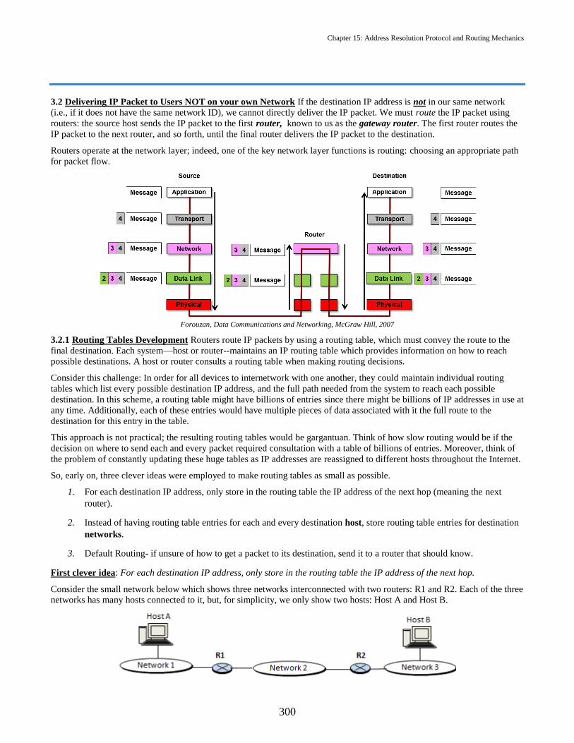
Chapter 15: Address Resolution Protocol and Routing Mechanics
300
3.2 Delivering IP Packet to Users NOT on your own Network If the destination IP address is not in our same network
(i.e., if it does not have the same network ID), we cannot directly deliver the IP packet. We must route the IP packet using
routers: the source host sends the IP packet to the first router, known to us as the gateway router. The first router routes the
IP packet to the next router, and so forth, until the final router delivers the IP packet to the destination.
Routers operate at the network layer; indeed, one of the key network layer functions is routing: choosing an appropriate path
for packet flow.
Forouzan, Data Communications and Networking, McGraw Hill, 2007
3.2.1 Routing Tables Development Routers route IP packets by using a routing table, which must convey the route to the
final destination. Each system—host or router--maintains an IP routing table which provides information on how to reach
possible destinations. A host or router consults a routing table when making routing decisions.
Consider this challenge: In order for all devices to internetwork with one another, they could maintain individual routing
tables which list every possible destination IP address, and the full path needed from the system to reach each possible
destination. In this scheme, a routing table might have billions of entries since there might be billions of IP addresses in use at
any time. Additionally, each of these entries would have multiple pieces of data associated with it the full route to the
destination for this entry in the table.
This approach is not practical; the resulting routing tables would be gargantuan. Think of how slow routing would be if the
decision on where to send each and every packet required consultation with a table of billions of entries. Moreover, think of
the problem of constantly updating these huge tables as IP addresses are reassigned to different hosts throughout the Internet.
So, early on, three clever ideas were employed to make routing tables as small as possible.
1. For each destination IP address, only store in the routing table the IP address of the next hop (meaning the next
router).
2. Instead of having routing table entries for each and every destination host, store routing table entries for destination
networks.
3. Default Routing- if unsure of how to get a packet to its destination, send it to a router that should know.
First clever idea: For each destination IP address, only store in the routing table the IP address of the next hop.
Consider the small network below which shows three networks interconnected with two routers: R1 and R2. Each of the three
networks has many hosts connected to it, but, for simplicity, we only show two hosts: Host A and Host B.

Chapter 15: Address Resolution Protocol and Routing Mechanics
301
Let's consider the routing table for Host A, and, in particular, let's look at the entry for Host B. Originally, the entry for Host
B would have been:
This entry means: To reach Host B, send the packet to router R1, who will in turn send it to router R2, who will then send it
to Host B.
The first clever idea recognizes that a host or router does not need to maintain information in its routing table about the full
path to a destination. Host A's routing table entry for Host B can be reduced to:
Since the packet will have to transit through router R1, and router R1 will have its own routing table that will tell it that the
next hop for destination Host B is router R2. R2 will have its own routing table that will tell it that the next hop for
destination Host B is direct delivery to Host B.
Second clever idea: Instead of having routing table entries for each and every destination host, store routing table entries
for destination networks.
Consider the network shown below, which shows a portion of the routing table for Host A.
Note that Host A has routing table entries for Hosts B, C and D and all three of these hosts (B, C and D) are on the same
network (Network 2). All packets delivered to these three hosts will be delivered to the same network. Thus, we can collapse
the three entries for B, C and D into a single entry in the routing table.
All hosts that connect to the same physical network share a common prefix (the network ID). Thus, routing tables only need
to contain network prefixes, and not complete IP addresses. Thus routing decisions are made based on table lookup where
routing tables keep only the network portion of the IP addresses (so the size of the routing table is, at worst, proportional to
the number of networks, not the number of hosts).
Third clever idea: Default Routing
To avoid large routing tables, group multiple destinations into a single default case. That is, when we want to route a packet,
we first check to see if the destination network ID is in the routing table; if not, send the packet to the default router.
Consider Host A in the network that follows:

Chapter 15: Address Resolution Protocol and Routing Mechanics
302
We see that Host A has a connection to Network 2 via router R1, and has a connection to the rest of the world via router R2.
It would make sense for Host A to have an entry in its routing table for Network 2. But it would make no sense for Host A to
have any entries for any other specific networks since any destination other than Network 2 will always be routed via router
R2. So, by default, if the destination is not Network 2, we should send the packet to R2.
Default routing is most useful when a host has a single connection to the Internet. Then routing is easy: If the destination's
network ID does not match mine, send the packet to the default router.
3.2.2 Routing Table Format The final result of implementing these three clever ideas is a routing table that looks as follows:
Let’s consider the following example network and develop the routing table to accompany it.
NOTE: It’s important to point out that we are making a LARGE logical leap from “there are other networks out there” to
“we know what other networks we are connected to.” Network discovery protocols and routing algorithms are the subject of
the next chapter. Supposing that we do know what networks we are connected to, we continue.
The Routing table for Router A would be:

Chapter 15: Address Resolution Protocol and Routing Mechanics
303
The routing table has a column for the Mask and Network Address of each network a router is able to. Applying the mask to
a destination IP address will extract the network address. The network address is common to all hosts on a particular network.
This is how the routing table is able to list destinations by network instead of individual hosts (clever idea 2).
The Next-Hop Address column holds the IP address of the next hop in the path to the destination (Clever Idea 1). Note that
every device connected to a network has an IP address on that network; here, Router RA has three connections to networks so
it has three IP addresses, one for each connection. Router RB has two connections, so it has two IP addresses. If router RA
sends to router RB, it must use 8.9.7.66 as the next-hop address since that is the IP address of router RB that connects to
router RA on the 8.9.7.64/26 network.
It is important to note that the next hop address is only used when the next hop is another router (that is, the “next hop” refers
to the next router in the path to the destination). If the router is connected directly to a network, direct delivery is used and the
next hop address in the table is simply “--”.
The Interface column lists the designated connection (or wire) label or that the IP packet will be sent over to get to the
destination. As you see on the network diagram above, every router has one or more connections leading from it; each
connection has a label For example, router RA has three connections labeled eth0, eth1 and eth2: router B has two
connections, labeled eth0 and eth1. For each router, these are the entries that would be in that router’s Interface column of
their routing table.
Finally, there is one entry for each network a router is able to reach and an additional default route added (clever idea 3). If
the /0 mask is applied to any IP address, the network address 0.0.0.0 will be extracted. This default route serves as a catch-
all.
3.2.3 Routing Table Mechanics Once a routing table has been created and a packet arrives at a router, we can outline how
the routing decisions are made as follows:
Step 1. A packet arrives at a router X, needing to be routed to its final destination.
Step 2. Looking at the IP packet header, router X examines the destination IP address. Router X applies the mask in the first
line of the table to the destination IP address:
Step 3. Router X checks to see if the extracted network ID matches the Network address shown on the first line:

Chapter 15: Address Resolution Protocol and Routing Mechanics
304
Step 4a. If it matches send the packet to the Next-hop address which is on this Interface:
Step 4b. If it does not match, repeat the process for the second line of the routing table. Continue to repeat as necessary until
a match is found. The default row of the table (with mask /0) will always provide a matching network address (0.0.0.0) if
none of the previous rows match.

Chapter 15: Address Resolution Protocol and Routing Mechanics
305
Practice Problem 15.11
The router R1 in the figure below connects the four different networks shown. The four networks connect to the router’s four
interfaces, labeled m0, m1, m2 and m3.
(a) Why does the router R1 have 4 different IP addresses?
Solution:
(b) How would you verify that the router address 180.70.65.135 on the m0 interface is indeed on the network
180.70.65.128/26 ?
Solution:
(c) Your friend says: "Wait just a minute! The two different networks 180.70.65.128/26 and
180.70.65.192/26 look very similar. Are these really two different networks…i.e., are these really two non-
overlapping blocks of addresses?" How would you reply?
Solution:
(d) Construct the routing table for router R1.

Chapter 15: Address Resolution Protocol and Routing Mechanics
306
We will see later that it is best to order the table by decreasing mask value…but let's proceed.
(e) Suppose an IP packet with destination IP address 180.70.65.140 arrives at router R1. Explain how the routing
table is used to make a routing decision.
Solution:
(f) Suppose an IP packet with destination IP address 201.4.22.35 arrives at router R1. What does it do?
Solution:
3.2.3 Longest Mask Matching Let’s consider now the following network previously referenced in Practice Problem 14.12.
Suppose a packet with destination address 201.4.22.35 arrives at router R1. What happens if the /22 network is listed
first in the routing table? The routing table may look like this:
By applying the mask /22 listed in the routing table for R1, we see the IP packet is routed out the wrong interface to the
wrong location. To prevent this problem, routing tables are sorted from longest mask to shortest mask. This principle is called
longest mask matching. So the corrected routing table for R1 would be:
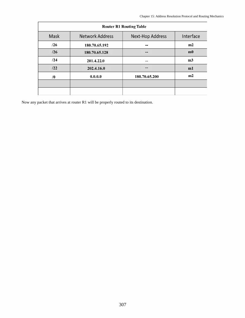
Chapter 15: Address Resolution Protocol and Routing Mechanics
307
Now any packet that arrives at router R1 will be properly routed to its destination.

308
THIS PAGE INTENTIONALLY LEFT BLANK

Chapter 15: Address Resolution Protocol and Routing Mechanics
309
CH. 15 Problems
1. Given the following ARP table, make the necessary change(s) to cause all Ethernet traffic destined for 192.168.14.10 to
flow to you (192.168.14.13) instead.
IP MAC
2. Why is the destination hardware address field of an ARP request message filled with all zeroes?
3. Why is an ARP request message sent to the broadcast hardware address?
4. Construct the routing table for router RB in the picture shown below.
5. Suppose router RB in problem 4 receives a packet with a destination address 3.3.3.38. What interface should the packet
be sent on? Explain how you arrived at your answer by numerically going through the routing process using the routing
table you created in problem 4.
6. What feature of the Address Resolution Protocol makes it particularly vulnerable to a spoofing attack?
192.168.14.8 AA:BB:CC:DD:EE:FF
192.168.14.9 AA:BB:AA:BB:AA:BB
192.168.14.10 CC:DD:CC:DD:CC:DD
192.168.14.12 EE:FF: EE:FF:EE:FF
192.168.14.13 A4:B5:C6:D7:E8:F9
192.168.14.21 C6:D7:C6:D7:C6:D7
192.168.14.25 E8:F9: E8:F9:E8:F9

310
THIS PAGE INTENTIONALLY LEFT BLANK

Chapter 15: Address Resolution Protocol and Routing Mechanics
311
Security Exercise 15
Part 1: Set up
Equipment required:
Your issued Laptop.
o Turn off the wireless adapter.
o Connect the blue Ethernet cable at your desk to your issued laptop.
A printed or electronic copy of this security exercise.
VMware Workstation
o Power on your Cyber2 VM, then click VM and Settings.
o Select Network Adapter and ensure that Connected, Connected at power on, and Bridged: Connected
directly to the physical network, and Replicate physical network connection state are selected or checked,
then click OK.
o Open a terminal in your Cyber2 VM and execute the command
sudo dhclient
Once it finishes, execute the command:
ifconfig eth1
Interface eth1 should be assigned an IP address of 192.168.XX.YYY, where XX is your classroom number and YYY is a
number between 3 and 254. If not, notify your instructor or lab technician.
Question 1: What is the IP address assigned to your Cyber2VM?
Question 2: What is your network mask in dotted decimal notation?
Question 3: What is your network mask in CIDR notation?

Chapter 15: Address Resolution Protocol and Routing Mechanics
312
Question 4: Apply the mask to your IP address to determine your network ID. What is your network ID?
Part 2: Routing Tables
As mentioned in the notes, it is not only routers that maintain routing tables: each host maintains a small routing table
internally, to let it know which interface (i.e., which Ethernet card) to use to communicate with your network and the
gateway router. Let’s examine your host’s internal (kernel) routing table. Type the following command:
route
After a few seconds, you should see something similar to this:
We can see from this table that our Cyber2VM’s default route is to 192.168.62.10.
Question 5: What do you think is the purpose of the kernel default route?
Now we are going to connect to the default gateway router (RouterA) and look at its routing table. Enter the following
command:
telnet <ip address of your default route>
When prompted for username, enter ‘mid’
When prompted for password, enter ‘shipman’
Once you have successfully logged on to Router A, the command line identifies you as mid@RouterA. Use the following
command to display its routing table:
mid@RouterA> show ip route
Question 6: Based upon the output of the command above, fill in Router A’s routing table. Ignoring the /32 and /8 networks,
list the entries in descending order by mask (As an aside, a /32 ‘network’ has all of its mask bits set to 1. Therefore, they only
match a single IP address – a network of one! Also known as host route, they are used here for router identification. The
127.0.0.0/8 network is reserved for the virtual loopback interface, so Router A can communicate with itself!)
Question 7: Suppose Router A receives a packet with destination address 98.139.180.149. Out of which interface will Router
A send the packet?
Question 8: Suppose Router A receives a packet with destination address 5.5.5.99. Out of which interface will Router A send
the packet?
Question 9: Can you use direct delivery to send messages to the host 192.168.60.150? Why or why not?
Logout of Router A so that we can continue:
mid@RouterA> exit

Chapter 15: Address Resolution Protocol and Routing Mechanics
313
Part 3: ARP
Launch Wireshark (as root) by selecting Applications, Internet, Wireshark (as root) from the system toolbar at the top of
your virtual machine.
Now we are going to begin a live packet capture. Click on Capture, Interfaces, eth1, Start, as shown in the following image:
If you don’t see any ARP traffic (shown in the following figure on the left), wait a minute, and you ought to see some ARP
traffic (shown on the figure to the right).
Once you have some ARP traffic in your capture, click STOP.

Chapter 15: Address Resolution Protocol and Routing Mechanics
314
Filter the captured traffic by typing “arp” as the search term in the filter box. This will allow you examine only the ARP
traffic:
Question 10: From Part 2 earlier, we know that our default route is to 192.168.62.10. Find a packet with an ARP reply from
the default router. What is its MAC address?
Close Wireshark.
Linux has several commands we can use to work with ARP. Here are several examples:
Command Description arp –n Display the ARP cache sudo arp –d <IP-ADDRESS> Clear entry for IP-ADDRESS from ARP cache sudo arping –f –I eth1 <IP-ADDRESS> Send ARP request to IP-ADDRESS using interface eth1
and stop after first successful reply.
In the terminal, use the commands in the above table to (1) display your ARP cache, (2) clear your ARP cache, and (3)
refresh your ARP cache for the default gateway, whose IP address is 192.168.xx.10, where xx is your classroom number.
Question 11: Can an ARP reply be sent without an ARP request?
Question 12: What is the goal of ARP spoofing?
Question 13: Can a computer with IP address 10.5.22.8 use an ARP spoofing attack against you? Why or why not?
Part 4: ARP Spoofing Demo
When instructed, your instructor will demonstrate ARP spoofing.
Question 14: During an ARP spoofing attack, what is the attacker’s target?

Chapter 15: Address Resolution Protocol and Routing Mechanics
315
Security Exercise 15 Answer Sheet
Name:
Question 1:
Question 2:
Question 3:
Question 4:
Question 5:
Question 6:
Question 7:
Question 8:
Question 9:
Question 10:
Question 11:
Question 12:

Chapter 15: Address Resolution Protocol and Routing Mechanics
316
Question 13:
Question 14:

Chapter 16: Autonomous Systems and Intranet Routing
Objectives:
(a) Discuss the major concerns with the use of a single protocol for the Internet.
(b) Describe the various autonomous system categories.
(c) Describe the fundamental algorithms used to construct routing tables.
(d) Describe how a routing table is developed using link state routing.
Up to this point, all we’ve looked at are a small set of Local Area Networks (LANs) which have been connected together
through a limited number of routers. As an example, consider the network topology below. It was comprised of only a few
small networks and a few routers which facilitated access to a single webserver.
Given this image we are able to create the routing tables for routers RA, RB and RC. In Chapter 15 we covered routing table
mechanics but we used routing tables that already existed. Armed with the knowledge of how to use routing tables, in this
chapter we learn where those routing tables actually come from (i.e., how they are derived).
But we are getting ahead of ourselves! Of course the group of networks would be easily manageable by one organization, but
the network depicted is not representative the Internet today. Today’s Internet comprises thousands of networks managed by
a countless number of different people spread across the entire globe all connected in some way to one another.
1. Internet Structure
It used to be that the structure of the Internet was like that of a tree, one central trunk (a.k.a. the backbone) that fed to all the
other downstream entities. End users connected to "service providers” which in turn connected to a single backbone. But the
Internet evolved over time. Multiple companies offered to provide backbone services, and gradually the original tree-like
structure was replaced by a multi-backbone structure. Additionally, multiple networks oftentimes decided to connect directly
together, avoiding the backbone altogether. The companies providing backbone services also recognized the utility in
connecting the backbones together.

Chapter 16: Autonomous System and Intranet Routing
318
Representation of Today’s Internet Structure.
Today there are several backbones run by different private corporations and governments to provide global connectivity. The
backbones are interconnected by peering points that allow connectivity between the backbones.
These peering points (Internet Exchanges) are voluntary connections between different networks which increase redundancy
and capacity. Although competitors, backbone providers desire these peering arrangements just in case one backbone is
suddenly asked to deliver more traffic than it is capable of (in which case it can send the excess to a competitor) or in case
one backbone is knocked offline completely.
The provider networks use the backbones for global connectivity, and, in turn, the customer networks utilize the services of
the provider networks. Any of the three (the backbones, the provider networks, or the customer networks) can provide
services (although at different levels) and can be called an Internet Service Provider (ISP).
Note some of the complexities in the figure above. For example, customer networks can connect to two (or more) different
provider networks in order to increase redundancy. Provider networks can connect directly to two (or more) backbones, again
for redundancy. Additionally, provider networks can connect directly to peering points within an Internet Exchange.
The structure of the Internet has as much to do with money and politics as it does with technology. Consider the fact
that the backbones are run by companies such as AT&T, Sprint and Verizon. Why them? These companies are formerly
telephone companies! They had the regulatory right-of-way clearance (i.e., the legal permission) to run long-distance
cable across the country, and the finances to support the operation.
Consider what the Internet would look like without peering points. We would not have a single Internet—we would have an
AT&T Internet, a Sprint Internet, a Verizon Internet, etc. Using peering points allows connectivity between the backbones
and preserves the idea of a single network even though the internet has grown far more complex.
2. Inherent Problems with a Single Routing Protocol
There are 7.3 billion people in the world, of which 3.6 billion are Internet users and both of those numbers are growing daily!
All of these users collectively produce a gargantuan amount of network traffic, which traverses many networks (with many,
many interconnecting routers) on the path from sender to destination. With all these users and devices, there is no way that
routing on the Internet can be accomplished using a single protocol. There are two major issues that prevent the use of a
single global routing algorithm on the Internet:
a. Scalability:
Can you imagine the size of the routing tables each router would have to maintain? Routing tables would become
absurd! These elephantine routing tables would mean that:
1) Searching for a destination would be extremely time consuming; and
2) Updating such unwieldy tables would create excessive amounts of needless traffic.
b. Administration:

Chapter 16: Autonomous System and Intranet Routing
319
Even if we could manage the scalability issue, a larger issue concerning network administration looms before us.
Suppose Provider Network X owns and runs a network that comprises a large number of routers (and
interconnecting edges). Suppose that Provider Network Y also owns and runs a network that comprises a large
number of routers and edges. Suppose the networks for both Provider Network X and Provider Network Y are
connected to the global Internet.
Now suppose that Provider Network X is really ElCheapo Inc, and is only concerned with cost and prioritizes
routing decisions based on cost. For Provider Network X, which promotes itself as "The cheapest ISP in town",
delay (time delay in communication) is not a concern.
Provider Network Y, on the other hand, is really SpeedyISP Inc, and focused on speed. For Provider Network Y,
which advertises itself as "The fastest ISP in town", cost is not a concern and seeks to route its data on the fastest
route (wants minimum time delay in communication).
Choosing a single routing algorithm that satisfies both Provider Network X and Provider Network Y would be
problematic. If the chosen algorithm minimizes the cost, Provider Network Y might be unhappy since the delays
might be intolerable. If the chosen algorithm minimizes the delay, Provider Network X might be unhappy since the
costs might be intolerable.
Even if we could find a routing algorithm that satisfies every organization on Earth (we can't!—but suspend
disbelief for a moment), other problems would remain. Would the Pentagon want its traffic to Afghanistan routed
via Iran, even if routers within Iran were along the best route? Even in peacetime, a country may decide that it would
like traffic that begins and ends in the country to stay exclusively within the country; for instance, we might want
traffic from San Diego to San Antonio to avoid Mexico, even though a straight line from San Diego to San Antonio
would travel through Mexico twice. In a commercial context, an organization might not want to carry traffic that
begins on a competitor's network and ends on another competitor's network, unless the competing networks are
willing to pay.
In a nutshell, the problem is that the owners of individual networks each want to set their own rules for routing
within their networks, without being concerned with what rules others are electing to follow.
So, then, what to do? Take advantage of the natural partitions on the Internet that exist and let entities that own portions of
the Internet run their own routing algorithms, independent from what others might be doing!
Practice Problem 16.1
Problems with routing protocols arise from issues of scalability or from issues of administration. Classify each of the
problems below as a problem of scalability or of administration.
(a) Verizon wants Netflix to pay for routing data through its network.
(b) Routers can only hold a limited amount of table entries.
(c) Extremely large routing tables cause delays in packet forwarding.
(d) Brazil and Europe decided not to route their traffic through the United States to avoid NSA spying.
Solution: (a)
(b)
(c)
(d)
3. Autonomous Systems
This problem is solved by partitioning the Internet into a number of separate networks, called Autonomous Systems (ASs).
The organization which owns the AS may independently choose the routing algorithm of its liking to be used within the AS.
If Organization X runs AS X, it is free to run a routing algorithm within its network that minimizes cost. If Organization Y
runs AS Y, it is free to run a routing algorithm within its network that minimizes delay. We say that each AS runs an interior
routing algorithm, which is, in common parlance, referred to as an interior gateway protocol. The Internet, then, is actually a
collection of Autonomous Systems. There are approximately 48,500 Autonomous Systems connected to the Internet today.
Each AS is under the control of a single administrator. ASs range in size and scope from corporations (e.g., General Motors
is an AS) to large Internet Service Providers (e.g., Comcast is an AS). Again: each AS can decide how it wants to route
within its own AS.

Chapter 16: Autonomous System and Intranet Routing
320
3.1 AS Designation Each autonomous system (whether small, medium, or large) is given an autonomous system number
(ASN) by the Internet Corporation for Assigned Names and Numbers (ICANN). Assigning an ASN follows a similar
procedure as the assignment of IP addresses blocks:
a. The Internet Assigned Numbers Authority (IANA) distributes ASNs.
b. IANA allocates blocks of ASNs to the five Regional Internet Registries.
c. Each Regional Internet Registry will distribute the ASNs as autonomous systems are developed and require an ASN.
d. Each ASN is a 32-bit unique identifier which is typically represented as a decimal value (e.g., AS6059 is the
University of Maryland).
Although there are different sizes of ASs, they are not categorized according to their size. Rather, they are categorized
according to how they are connected to other ASs.
3.2 AS Categories
Stub AS
a. A stub AS has only one connection to one other AS.
b. Data traffic either originates or terminates in a stub AS. In other words, the stub AS is either a source or destination
of data.
Multihomed AS
a. A multihomed AS may have more than one connection to other ASs, but doesn’t allow data to transit through it.
b. Data traffic either originates or terminates in a multihomed AS.
c. A customer network is a good example of a multihomed AS. In the picture below, the customer network will not
support traffic that begins with a user in ISP1 and is destined for a user in ISP2.
Transit AS
a. A transit AS is connected to more than one AS.
b. A transit AS allows traffic to pass through.
c. Provider networks and the backbones are examples of the transit ASs. In the picture that follows, the transit AS will
support traffic that begins with a user in ISP 1 and is destined for a user in ISP 2.

Chapter 16: Autonomous System and Intranet Routing
321
Practice Problem 16.2
Consider the picture below, showing the interconnection of four ASs. Here, traffic can route from New York through Paris
and Cannes and eventually get to Bonn, but traffic that goes from New York to Berlin to Bonn and on to Stuttgart cannot
proceed onward to Cannes. What are the categories of each of the ASs?
Solution:
So to deal with the difficulties associated with pleasing everyone and implementing a single routing protocol, the Internet has
been partitioned into separate autonomous systems. A shared routing protocol, which we refer to as an intra-domain
(intranet or interior) routing protocol decided upon by the organization exercising administrative control of the AS is used
to pass data between the routers within the AS. We can route among multiple ASs by using an inter-domain (internet or
exterior) routing protocol that all ASs must agree to.
This chapter concludes with Intra-domain routing protocols (i.e., within an AS). Chapter 18 will introduce Inter-domain
routing protocols (i.e., between ASs).
4. Intranet Routing
Up until this point we have talked about simple examples where one router is the only path to one network. In reality, things
are much different. Often there can be multiple paths from one network to another. The question is not just how to get from
Router A to Router B, but how to get there using the best route. Routers use routing protocols to build their routing tables.
Routing protocols are intended to:
Communicate network topology information to each router.
Determine how individual routers will use this information to make routing decisions (i.e., determine how individual
routers will use this information to construct routing tables).
4.1. Networks as Graphs To develop routing algorithms we model a computer network as a graph: the nodes of the graph
are the routers. An edge in a graph represents a communication link between two routers.
On each edge between two routers, we assign a weight. This weight might be distance, cost, queuing delay, or some other
factor of interest. Our problem: Find the path from a given source node to a destination node which minimizes the total
weight. To determine the path, we can think of the weights as follows:
AS1 AS3
AS2
AS4

Chapter 16: Autonomous System and Intranet Routing
322
If our weights represent: Then we are interested in:
distance shortest path
cost cheapest path
queuing delay fastest path
Recall from Chapter 15, that one simplification we make in our routing tables is to list only the next hop. Routers make local
routing decisions – i.e., they decide the next place to send a packet addressed to a specific destination. But they must make
this decision based on some understanding of the global network picture (the next hop is the hop on the most cost effective
route!). So, each router needs global information about the network.
To get an idea of what a routing table should look like for a more interconnected network than those we have treated up to
this point, consider the network shown below on the left, where each circle represents a router. Suppose the weight of each
link is one. The question is: What should the routing table be for Router 1? The answer to this question is shown in the table
on the right.
Practice Problem 16.3
Consider the network shown below, where the numbers on the edges indicate the cost of using that edge. For example, the
cost of using the link from Router A to Router B is 1, whereas the cost of using the link from Router A to Router D is 4.
(a) Fill in the routing table for Router A, and include the total cost.
Solution:
Destination Next Hop Total Cost
B
C
D
E
F
(b) If all routers have the correct routing tables, what is the path that an IP packet travels from Node A to Node F?
(Note that to state a path, you just need to state the sequence of routers encountered along the path; for example,
one possible path from Router A to Router F is A-D-E-F.
Solution:
(c) What is the total cost of the path you selected in Part (b) above?
Solution:
1
3
2
8
4 6
5
10
7
9
A
ED
CB
F
1
3
1
1
4
2
1
4

Chapter 16: Autonomous System and Intranet Routing
323
So, now that we know what routing tables should look like, we ask the question: How do routing tables actually get put
together? You likely solved the preceding example by looking down on the network and performing a visual analysis of the
picture. Routers do not have the ability to hover over a picture of the network, and they do not have human visual skills at
their disposal for use in analyzing a diagram. So how do they do it?
4.2 Approaches to Routing Routing protocols employ one of three approaches to gathering and using routing information:
Link-State Routing, Distance Vector Routing, and Path-Vector Routing. The Open Shortest Path Routing (OSPF) is a widely
used intranet routing protocol in TCP/IP networks, and thus we seek to understand the approach it utilizes: Link State
Routing.
Link State Routing
A. Two key ideas:
Each router learns the full network topology. That is, each router learns a complete picture of the network graph–
including the routers, the links and the link weights.
Knowing the complete network picture, each router independently computes the optimal routes to each destination
and constructs their routing table.
B. Learning the topology
The first bullet above says “Each router learns the full network topology.” So, in link state routing, how do routers come to
know the network topology? Here's how:
Each router learns its neighbors’ addresses by sending "Hello" packets to which its neighbors reply.
Each router determines the weight of each of its links to its neighbors. For example, if these weights represent time
delays, the routers might determine how long it takes to receive a reply, and use that as the weight. If the weight is a
cost, the router might “know” the costs associated with each link based on data entered by a network administrator.
Each router then transmits packets that tell information about that individual router's links to its neighbors, called Link
State Packets (LSP).
For instance. After sending “Hello” Packets and discovering its neighbors and costs to them, Router 26 sends a packet that
essentially says:
Or, somewhat more formally, it transmits a packet that conveys the following table.
By sending this packet, a router informs the network about the status, or state, of each of its links. Hence, this methodology is
called Link State Routing and these packets are called Link State Packets (LSPs). This info will then be used by others to
construct routing tables.
These LSPs are distributed to all other routers using "controlled flooding": When a router receives a LSP, it sends it to all of
its neighbors. A router keeps track of which LSPs it has seen, and only floods them the first time they arrive.

Chapter 16: Autonomous System and Intranet Routing
324
Now…think about this: After each router has sent its LSP, and after each LSP has been circulated to all the other routers,
then does each router have a full and complete picture of the network topology? The answer is yes!
C. Route Optimization
The second key idea says “each router independently computes the optimal routes to each destination and constructs a routing
table.” The routers have all received link state packets and know the topology of the network, but how do they determine the
optimal route? The answer: Each router determines the shortest path (i.e., the path with the lowest total weight) from itself to
every other node in the network by running a famous algorithm named "Dijkstra's Algorithm". This relatively easy algorithm
is covered in any Discrete Math textbook, but will not be covered in EC310.
Practice Problem 16.4
Given the following network map with the weights of edges between routers:
(a) Construct the Link State Packet (LSP) that Router C would send to its neighbos.
Solution:
(b) After Router G runs Dijkstra's Algorithm, what would be the optimal route from Router G to Router B, and
what would be the total cost of this route?
Solution:
D. Topology changes. What if a link dies? For instance, in the picture the pevious page, what if the link connecting Router 18
to Router 26 should die?
In link state routing, whenever a router detects a change in the state of its links, it sends a new link state packet. Thus, if the
link connecting Router 18 to Router 26 should die, Router 26 will transmit a new LSP with the entries:
Note that Router 18 will also detect the loss of a connection to Router 26 and transmit a new LSP as well. These new LSP's
will then propagate to all other routers via controlled flooding.
You might be wondering: Won't there now be conflicting information in the other routers? For instance, there will now be
two pieces of information from Router 26:
The old LSP from Router 26 that had info about the link to Router 18

Chapter 16: Autonomous System and Intranet Routing
325
and the revised LSP without info about router 18:
Which of these should another router in the network choose to use to build its network picture and run Dijkstra's Algorithm?
To solve this perplexing predicament, yielding a righteous resolution to this difficult dilemma, and thus causing midshipmen
merriment, each LSP has a sequence number. That is, a Router stamps its first LSP with sequence number 1, its second LSP
with sequence number 2, and so forth. Higher sequence numbers override lower sequence numbers. So, when other routers in
the network receive a new LSP from Router 26, they will notice that it has a higher sequence number than the previous LSP,
and they will delete the previous (outdated) LSP.
Okay…each router has to send LSPs when the router is first connected to the network, and also has to send LSPs whenever
the network topology changes. Are there any other times that routers send LSPs?
The answer is Yes! Routers send LSPs periodically, just to make sure all routers are “on the same page.”
5. Important Notes
Recall from Chapter 15 that routing tables were simplified with three “clever ideas”
List Networks instead of Hosts
List Only the next Hop
Default Routing
The routing tables in this chapter are a simplification of the ones we looked at in Chapter 15. Routers first discover one
another and the optimal paths to each other. But must subsequently exchange information about the networks each router can
reach. The entries in the routing tables above represent routers. Destinations “A”, “B”, “C” become entries for a mask and
network address for the networks the router is directly connected to, and the next hop becomes an IP address of the router
which is the next hop. It’s important to note the routing tables in this chapter are a simplification. The networks that are
connected to the router have been simplified to represent the network in the form of a graph. But the final product is what we
have seen in the previous chapter.
The third clever idea was default routing. Intranet routing means that each router maintains a routing table that reflects the
known topology of the AS of which it is a part. Certainly there are destinations not within our AS. We will see the utility of
default routing when we discuss Internet Routing in Chapter 18!

326
THIS PAGE INTENTIONALLY LEFT BLANK

Chapter 16: Autonomous System and Intranet Routing
327
CH. 16 Problems
1. Which of the following are examples of why a single-protocol Internet would be a concern? (Choose all that apply)
(a) Across the globe, individual network administrators each want to set their own rules for routing within their
networks without being concerned with what rules others are electing to follow.
(b) The world's network administrators unanimously agree on the best single routing algorithm that satisfies all of
their respective networking and routing needs.
(c) Under a single-protocol internet structure, searching for a destination would be extremely time-consuming.
(d) Under a single-protocol internet structure, updating the routing tables would create excessive amounts of
needless traffic.
2. Fill in the appropriate Autonomous System (AS) category or categories under each of the descriptions below. (Choose
from: Stub, Multihomed, and Transit)
(a) An AS is connected to more than one other AS and it allows traffic to pass through it.
(b) An AS has only one connection to another AS, and it can act as a source or destination of data.
(c) An AS may be connected to one or more ASs, and it does not allow data to pass through it, but it can still act as
a source or destination of data.
(d) A 'Provider Network' is a good example of this type of AS.
(e) A 'Customer Network' is a good example of this type of AS.
3. Consider the network whose graph is shown below.
(a) To which routers does Router C send its LSP?
(b) Would Router G ever get Router C’s LSP?
(c) Sketch the LSP sent by Router C.
(d) Show the routing table for Router C
(e) Show the routing table for Router E
Continued on Back

Chapter 16: Autonomous System and Intranet Routing
328
4. Determine the routing table for Router A in the figure below.
5. On the right is a partially filled out routing table for Router C. Complete the partial routing table for the destinations
listed below.
Destination Next element Total cost
A
B
C --- 0
D
E

Chapter 16: Autonomous System and Intranet Routing
329
Security Exercise 16
Part 1: Set Up
Let’s put to use the networking skills we have learned to date to better understand routing at the router level.
Equipment required:
Your issued Laptop.
o Turn off the wireless adapter.
o Connect the blue Ethernet cable at your desk to your issued laptop.
A printed or electronic copy of this security exercise.
o If printed, separate the network diagram and answer sheet and have them ready to fill in.
VMware Workstation
o Power on your Cyber2 VM, then click VM and Settings.
o Select Network Adapter and ensure that Connected, Connected at power on, and Bridged: Connected
directly to the physical network, and Replicate physical network connection state are selected or checked,
then click OK.
o Open a terminal in your Cyber2 VM and execute the command:
sudo dhclient
Once it finishes, execute the command:
ifconfig
Your screen should look similar to Figure 1 below. Interface eth1 should be assigned an IP address of 192.168.XX.1YY,
where XX is your classroom number and YY is a number between 0 and 254. If not, notify your instructor or lab technician.

Chapter 16: Autonomous System and Intranet Routing
330
Figure 1 – ifconfig executed after initial lab setup.
Part 2: Where am I?
Locate EC310 MID on your network diagram. This is your Cyber2 VM which has just joined a virtual network in a virtual
world. You have an Ethernet card in your virtual machine called eth1 that has been assigned an IP address on the virtual
network.
Identify a) your IP address and compute b) your network address and network mask in CIDR notation using the
information from ifconfig.
Label parts a) and b) of your network diagram.
In order for your packets to leave this virtual network and venture out into the virtual world, your virtual machine must send
them to a Gateway Router. Router A is serving this purpose for the network you are connected to. To send your packets to
Router A and out into the world, you must know its IP address first.
Execute the command:
route –n
Identify the IP address of the Gateway Router. Look under the Gateway column of the Kernel’s IP routing table
(see Figure 1 for reference). Recall that address 0.0.0.0 is used to represent any IP address and is not the
Gateway Router’s address.
Label part c) of your network diagram.
Part 3: Where do I go next?
In this virtual world there is an important website located at http://www.usna.edu.

Chapter 16: Autonomous System and Intranet Routing
331
Verify the website www.usna.edu exists by opening Firefox and navigating to the website address. Access Firefox
by selecting Applications, Internet, Firefox from the system toolbar at the top of your virtual machine (see the figure
at the top of the next page for reference).
Browse the website to see what information is available.
Question 1: Who maintains the website at www.usna.edu?
In order for your virtual machine to access this website it first must know the webserver’s IP address. Recall from SY110 that
the Domain Name System (DNS) provides a convenient way for us to remember a website’s name rather than a bunch of
numbers for an IP address. Both are interchangeable through a series of ‘phonebooks’ (DNS name servers) on the Internet
that perform lookups on our behalf. If you provide to the phonebook (DNS name server) the name of the webserver you
would like to access, it will give you its IP address in response or vice versa. From the command line we use the dig
command. The most concise output comes from adding +short attribute after the website name. For example in Figure two
below we see dig cynicalmids.tumblr.com +short. (Note: try dig without the +short attribute and see the
difference.)
Figure 2 – DNS query and response.
The query above was generated using a utility called dig to find the IP address for www.cynicalmids.tumblr.com. dig
allows you to query a DNS name server and resolve its IP address.
Identify the IP address of the website www.usna.edu by executing the following command:
dig www.usna.edu +short
Label part d) of your network diagram with the IP address belonging to the eth0 interface of the webserver
www.usna.edu.
Part 4: How do I get there?
There are two methods to discover information about the path between you and the webserver www.usna.edu. The first
method is the utility ping with the record route option. It will tell you the IP addresses of the OUTGOING interfaces along
the way to and from the final destination.

Chapter 16: Autonomous System and Intranet Routing
332
Figure 3 – Example use of ping with record route option.
For example, in Figure 3, after the command
ping –R –c1 –n 2.2.2.15
is executed, the OUTGOING interfaces are listed in order beginning with:
1) 3.3.3.5 – the host computer’s interface.
2) 2.2.2.1 – Router A’s eth1.
3) 2.2.2.15 – the webserver’s interface.
The OUTGOING interfaces of the return trip are listed in order beginning with:
4) 2.2.2.15 – the webserver’s interface.
5) 3.3.3.1 – Router A’s eth0.
6) 3.3.3.5 – the host computer’s interface.
Identify the IP addresses of the interfaces traversed between you and the webserver www.usna.edu using the ping
command (do not forget the –R and –c1 and –n options).
Label parts e) through g) of your network diagram.
The second method is the utility traceroute, which works similar to ping, except it tells you the address of the
INCOMING interface along the path between you and your destination (one-way trip, nothing for the return path). In that
respect, for this SX it is less useful than ping. For example, in the figure that follows, if you entered the command
traceroute –n 2.2.2.15, the INCOMING interfaces are listed in order beginning with:
1) 3.3.3.1 – Router A’s INCOMING interface.
2) 2.2.2.15 – the webserver’s interface.
Execute a traceroute to the webserver www.usna.edu (do not forget the –n option).
Question 2: Compare your traceroute results with your network diagram. Even though it provides less information than
ping, does the information obtained from traceroute agree with the information from the ping command?

Chapter 16: Autonomous System and Intranet Routing
333
Figure 4 – Example of traceroute command.
Part 5: In anyone else out there?
Routers B and C are also present in this virtual world and are responsible for forwarding packets between the networks they
are connected to and learning about other networks from other routers. Recall that routers learn about each other’s networks
by using a routing protocol such as the Open Shortest Path First (OSPF) protocol. In OSPF, routers use Link State Packets
(LSPs) to communicate with each other and learn about the network topology. Let’s take a closer look at this communication.
Launch Wireshark (as root) by selecting Applications, Internet, Wireshark (as root) from the system toolbar at the
top of your virtual machine.
Open the packet capture labeled hello.pcap in the ec310code folder in your home directory.
Examine the captured OSPF hello packets in the packet details pane. Be sure to expand the OSPF Header and
the OSPF Hello Packet portions (see the figure at the top of the next page for reference). These packets were
captured from one of the routers in your virtual world.

Chapter 16: Autonomous System and Intranet Routing
334
Recall that in OSPF routers send Hello Packets at a specific interval in order to let other routers know they are alive. This
interval is called the Hello Interval.
Question 3: Using the information in the captured Hello Packets, what is the Hello Interval for the router they were
captured from? Verify the Hello Interval by observing the amount of time between two OSPF hello packets in your
packet capture. Is it equal to the Hello Interval?
If after a certain amount of time a router does not receive a Hello Packet from another router it deems that router to be ‘dead’
and removes all routes that were advertised by that router. The time duration before a router is declared dead is known as the
Dead Interval. This allows OSPF to respond well to dynamic changes in the network topology.
Question 4: What is the Dead Interval for the router’s captured Hello Packets? If you could stop a router’s hello
packets from being flooded to the network, would you disable that router?
Hello Packets also serve the important function of beginning a neighbor association between two routers when they first
meet. Before the new routers agree to swap routing information they must agree on a basic set of parameters and become
neighbors first. A router begins this process by identifying itself in the OSPF Header of the packet under the Source
OSPF Router field.
Question 5: Look inside the OSPF Header of a captured Hello Packet. What IP address is listed in the Source OSPF
Router field (note: this IP address does not begin with 192.168.65.XX)?
This IP address is very important. It is known as the Router’s ID and it uniquely identifies this router to all other routers.
Who is responsible for assigning IP addresses anyway? The network administrator is responsible for assigning IP addresses
among their many other tasks in maintaining the network. They assign blocks of IP addresses as part of the design of the
network architecture to best meet the needs of their clients.
What are the routers talking about with each other and why do they need to communicate so often? There are a number of
internal measures routers use in order increase efficiency and prevent unnecessary information from clogging up the network,
such as electing a Designated Router (DR) and Backup Designated Router (BDR) and managing Link State Updates (LSU).
To learn more about OSPF, see http://www.ietf.org/rfc/rfc2328.txt.
Part 6: Could anyone hurt me?
Lastly, an evil instructor is also present in this virtual world. The evil instructor is located on the 5.5.5.0/25 network and
your final task is to find him or her. nmap is a powerful utility which allows us to scan networks and identify which hosts are
active among many other useful tasks.
Execute the command below to scan the 5.5.5.0/25 network and determine which hosts are ‘up’ (i.e., active). It
may take a few minutes.
nmap –sP 5.5.5.0/25
Use traceroute or ping to identify the path to each of the hosts identified as ‘up’ by nmap.
Question 6: Using your network diagram and the results from traceroute or ping, what is the most likely IP address of
the evil instructor?
Confirm the IP address identified with your instructor or lab technician.
Label part h) of your network diagram.
Use traceroute or ping to verify the interfaces between you and the evil instructor.
Label parts i) through k) on your network diagram.

Chapter 16: Autonomous System and Intranet Routing
335
Part 7: Clean up
VMware Workstation
o In the VMware Workstation menu click VM and Settings.
o Select Network Adapter and ensure that Connected, and Connected at power on, are unchecked, and
ensure that Host-only: A private network shared with the host is selected or checked, then click OK.
o Shutdown your Cyber2 VM Disconnect the blue Ethernet cable. Turn on your wireless adapter.

336
THIS PAGE INTENTIONALLY LEFT BLANK

Chapter 16: Autonomous System and Intranet Routing
337
Security Exercise 16 Answer Sheet
Name:
Question 1:
Question 2:
Question 3:
Question 4:
Question 5:
Question 6:

338
THIS PAGE INTENTIONALLY LEFT BLANK

339

340
THIS PAGE INTENTIONALLY LEFT BLANK

Chapter 17: The Man-In-The-Middle Attack
Objectives:
(a) Describe the Man-In-The-Middle (MITM) attack and list what advantages it provides the attacker.
(b) Construct a routing table based on a network diagram and manipulate a routing table to exploit a specific target.
(c) Describe the steps that should be taken to prevent false route injection and identify who is responsible for performing these
preventative actions and how they can be applied.
(d) State the fundamental principle of communication as it relates to security.
1. Trust!
Where are we at in our understanding of how networks interconnect? We’ve talked about routing algorithms and how routing
tables are constructed; we’ve talked about the layers and protocols involved in networking; we’ve also talked about
addressing schemes and specifically how MAC addresses and IP addresses are used; but, what is the point of all this?
Much like the host section in the first six weeks of EC310, we need to understand how networks work before we can
manipulate their operation and violate the principles of security. What is the underlying assumption between routers in the
routing algorithms they use to construct their routing tables?
The assumption is that each router can trust the information that other routers are sending it.
That is, Router A assumes by default that Router B is telling the truth about the state of its links or the distance between it
and other routers. But what happens when that is not the case? Would a machine ever lie to another machine?
Practice Problem 17.1
Consider the network below. Depict the routing table for RD.
Solution:

Chapter 17: The Man-In-The-Middle Attack
342
Practice Problem 17.2
But what if Router C was evil and began to falsify information about its link to Router A in the LSP it was sending? How
would the routing table change?
Solution:
What does this mean for all of Router D’s traffic destined for Router A?
More importantly, why would Router D’s traffic go through Router C instead?
Of note, what would happen to Router A’s traffic destined for Router D?
2. Pillars of Information Assurance
Fortunately, machines cannot lie to one another, but the humans that operate the machines do lie (or make mistakes) and can
force the machines to do the same.
In the previous example, we saw how a simple lie about the distance between two routers could change the direction of traffic
flow within the network, but why is this of concern? Even with this manipulation, if Router D wanted to send packets to
Router A, won’t the information be delivered just as before? (note that only Router D is fooled by Router C’s lie. Router A’s
table is not affected by Router C’s lie and it will still route to Router D via Router B with a total cost of 6. This is because
Router A knows its distance to Router C.)
Now that Router C is in the middle of Router D and Router A, it can:
1. Observe the traffic moving between these devices.
2. Change the information moving between these devices.
3. Stop the traffic from moving between these devices.
Why is this an issue? Recall from SY110, there are five pillars of information assurance we want to preserve when offering
services through routers and other information systems.
1. Confidentiality – protection of information from disclosure to unauthorized individuals, systems, or entities.
2. Integrity – protection of information, systems, and services from unauthorized modification or destruction.
3. Availability – timely, reliable access to data and information services by authorized users.
4. Non-repudiation – the ability to correlate, with high certainty, a recorded action with its originating individual or
entity.
5. Authentication – the ability to verify the identity of an individual or entity.
Practice Problem 17.3
What primary pillar of information assurance is violated in each thing Router C can do once it is in the middle of Router D
and Router A?
(a) The ability to observe traffic violates:
(b) The ability to change traffic violates:
(c) The ability to stop traffic violates:

Chapter 17: The Man-In-The-Middle Attack
343
3. The Man-In-The-Middle (MITM) Attack with ARP Spoofing
This type of problem is called the Man-In-The-Middle attack.
We have seen this once already in Chapter 15. Specifically, the technique used to conduct the MITM attack in Chapter 15
was called ARP-Spoofing because to redirect another computer’s traffic on a single network required your computer to tell a
specific lie about the association between its
MAC address and IP address
Much like a nasty rumor in the Brigade, that lie had to spread around for it to be effective. Similarly, you included your own
MAC address with the target’s IP address through multiple unsolicited ARP-Replies to convince everyone on your local
network that your machine was the target host. Finally, everyone on your local network had to believe your lie for you to
begin receiving packets destined for the target machine.
Do you think it is possible for something like this to happen on a bigger scale? That is, instead of a Man-In-The-Middle
attack on one network as with ARP-spoofing, can this happen between multiple networks?
Yes it could happen, and things similar to this have already happened, but to understand how requires a bit more
understanding of the how networks interconnect. However, just as before with ARP-Spoofing, there are four critical steps
that must occur for an attacker to make this possible.
1. Take control of a machine on the network and manipulate its operation.
2. Force the machine to tell the “right” kind of lie.
3. Force the machine to spread the lie around.
4. Force other machines to believe the lie.
4. Man in the Middle Attack with False Route Injection
Let’s say there is an important website that all midshipmen need to access to in order to prepare for EC310 each day. That
website is located at IP address 4.4.5.155 on the network 4.4.5.0/24. The midshipmen who need access to it are
located on network 192.168.65.0/24, and have one of the 253 available host IP addresses assigned to their laptops.

Chapter 17: The Man-In-The-Middle Attack
344
Practice Problem 17.4
Construct the routing table for Router A.
Now, let’s pretend there is an evil instructor (because aren’t all instructors evil?) located on the 5.5.5.0/25 network that
wants to prevent students from reaching the EC310 website at 4.4.5.155. What would that instructor need to do in order
to make the student’s traffic go to some place they did not intend?

Chapter 17: The Man-In-The-Middle Attack
345
a) First, the instructor will need to: take control of a machine on the network and manipulate its operation.
Being an instructor, ITSD has graciously allowed him (or her) privileged access to his office computer for ‘academic
research’, but nowhere else. ITSD has restricted the instructor’s privileged access in order to prevent him from making any
changes that could affect other computers on the network. Therefore, the instructor will need to manipulate his computer in
such a way where it can alter the flow of traffic across the networks and deny midshipmen access to the course website. To
accomplish this, he decides to turn his computer into a router using a special software tool called Loki.12 This tool ‘speaks’
the Open Shortest Path First (OSPF) protocol, which will enable the injection of false routing information into the
networks.
b) Second, the instructor will need to: force his router to tell the “right” kind of lie.
But what is the “right” kind of lie to tell? Well, that depends on the effect the instructor wants to have on the networks. For
example, if the instructor wanted to cause a panic across the entire Brigade, he or she might say that “buffalo chicken
sandwiches will no longer be offered in King Hall.” However, if the aim was only to terrorize the students in his EC310
section, the instructor could say “you will have a quiz tomorrow over Lessons 1 through 15 worth 99% of your final grade.”
The instructor’s goal is to stop the students’ traffic from reaching the EC310 web server located at 4.4.5.155. To do this
the instructor would like to direct the students’ traffic to a different location where their web requests will go unanswered.
Knowing that routers transmit information to the destination that matches the longest network prefix in their routing table,
12 Loki is a Python based framework implementing many packet generation and attack modules for Layer 3 protocols. It was
developed by ERNW, an IT security service provider, in 2010. See https://www.ernw.de/research/loki.html for more details.
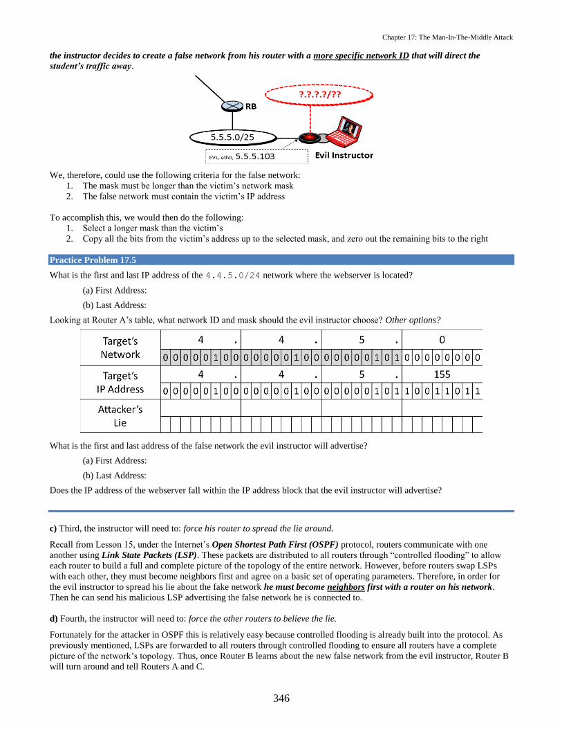
Chapter 17: The Man-In-The-Middle Attack
346
the instructor decides to create a false network from his router with a more specific network ID that will direct the
student’s traffic away.
We, therefore, could use the following criteria for the false network:
1. The mask must be longer than the victim’s network mask
2. The false network must contain the victim’s IP address
To accomplish this, we would then do the following:
1. Select a longer mask than the victim’s
2. Copy all the bits from the victim’s address up to the selected mask, and zero out the remaining bits to the right
Practice Problem 17.5
What is the first and last IP address of the 4.4.5.0/24 network where the webserver is located?
(a) First Address:
(b) Last Address:
Looking at Router A’s table, what network ID and mask should the evil instructor choose? Other options?
What is the first and last address of the false network the evil instructor will advertise?
(a) First Address:
(b) Last Address:
Does the IP address of the webserver fall within the IP address block that the evil instructor will advertise?
c) Third, the instructor will need to: force his router to spread the lie around.
Recall from Lesson 15, under the Internet’s Open Shortest Path First (OSPF) protocol, routers communicate with one
another using Link State Packets (LSP). These packets are distributed to all routers through “controlled flooding” to allow
each router to build a full and complete picture of the topology of the entire network. However, before routers swap LSPs
with each other, they must become neighbors first and agree on a basic set of operating parameters. Therefore, in order for
the evil instructor to spread his lie about the fake network he must become neighbors first with a router on his network.
Then he can send his malicious LSP advertising the false network he is connected to.
d) Fourth, the instructor will need to: force the other routers to believe the lie.
Fortunately for the attacker in OSPF this is relatively easy because controlled flooding is already built into the protocol. As
previously mentioned, LSPs are forwarded to all routers through controlled flooding to ensure all routers have a complete
picture of the network’s topology. Thus, once Router B learns about the new false network from the evil instructor, Router B
will turn around and tell Routers A and C.

Chapter 17: The Man-In-The-Middle Attack
347
Practice Problem 17.6
What will Router A’s routing table look like, once it hears the lie about the fake network from Router B?
When a student sends a packet destined for the webserver at 4.4.5.155, where will Router A forward their packet? Will
the EC310 students ever be able to reach the course web page?
Solution:
Do you think it is possible that something like this could ever happen on the Internet? Unlike the previous example, the
Internet consists of hundreds of thousands of networks stretched across the entire globe. Could it be possible for someone to
change the way traffic flows across such a big and complex distributed system?
Yes it could happen, and similar things like this have already happened, but to understand how requires a bit more
understanding of the Internet first. Specifically, we need to understand the fundamental protocol of the Internet, the Border
Gateway Protocol (BGP). That is, before we can become a locksmith (of the Internet), we need to know a bit more about
how the lock (the Internet) operates.

Chapter 17: The Man-In-The-Middle Attack
348
5. Protection against False Route Injection
How can we stop such malicious behavior? Recall that by default routers trust the information other routers are sending, but
this does not have to be the case. The Open Shortest Path First protocol has two authentication mechanism built in to protect
against false route injection. The first is a simple plaintext-password added to all LSPs so each router can authenticate the
information it is receiving. If a router sends a LSP without the appropriate password, then the LSP is rejected.
The second method is an MD5-hash of the shared secret key. Recall from SY110, that hashing is a ‘one-way’ encryption
technique that produces the same message digest (i.e., encrypted output) given the same input string. Additionally, while it is
easy to hash the input string, it is very hard to identify the input string given only the message digest (remember the Rubik’s
cube?). In OSPF, routers can send the hash of the shared secret key along with their LSP to authenticate themselves with
other routers. Of course, all routers must know the shared secret key in advance. This may seem trivial at first, but consider
the number of routers at a place like Google or Amazon Web Services where there are literally thousands of routers.
Lastly, separate from these two authentication mechanisms, most implementations of OSPF allow for creation of passive
interfaces. Just like when your roommate starts getting on your nerves and you tune him or her out by putting your
headphones on, routers can do the same thing. Once a network administrator sets up a passive interface on a router, the router
will ignore all routing information being sent over that interface. However, this requires network administrators to make
smart decisions when setting up the topology of their networks and configuring their routers.
Practice Problem 17.7
Briefly describe two technical solutions to protect against false route injection and identify who is responsible for
implementing them.
Solution #1:
Solution #2:

Chapter 17: The Man-In-The-Middle Attack
349
CH. 17 Problems
1. What is the underlying assumption between routers in the routing algorithms they use which makes it possible to conduct
a Man-In-The-Middle (MITM) attack?
2. What three things can an attacker do to your network traffic in a Man-In-The-Middle (MITM) attack and what pillar of
Information Assurance is affected during each?
3. An attacker is located on the 5.6.7.0/24 network and wants to prevent midshipmen from reaching a website at
8.8.8.26. He turns his computer into a router using Loki to advertise a false network to Router C.
(a) Construct the routing table for Router C. Use the template shown below:
(b) Looking at Router C’s routing table, what network address and mask should the attacker choose? In answering
this question, complete the table below.

Chapter 17: The Man-In-The-Middle Attack
350
(c) Complete the routing table entry below with your answer from (b) and draw a line into Router C’s routing table
showing where the attacker’s false network would go.
(d) What is the first and last IP address of the false network you chose for the evil instructor?
(e) Does the IP address of the webserver fall within your choice for the evil instructor’s false network?
(f) Given your answer to part (e), whenever a midshipman sends a packet destined for the webserver at 8.8.8.26
where will Router C forward their packet? Will the midshipman ever be able to reach the important website?
(g) List and briefly describe two technical solutions that could be implemented on Router C to prevent the evil
instructor from injecting false routing information.
(h) Who is responsible for implementing these security measures in a network?

Chapter 17: The Man-In-The-Middle Attack
351
Security Exercise 17
Part 1: Set up
It is interesting to hear the theory behind a Man-In-The-Middle attack, but it is better to experience it yourself.
Equipment required:
Your issued Laptop.
o Turn off the wireless adapter.
o Connect the blue Ethernet cable at your desk to your issued laptop.
Your completed network diagram from SX#16 and a printed copy of this security exercise.
o Separate the answer sheet and have it ready to fill in.
VMware Workstation
o Power on your Cyber2 VM, then click VM and Settings.
o Select Network Adapter and ensure that Connected, Connected at power on, and Bridged: Connected
directly to the physical network, and Replicate physical network connection state are selected or checked,
then click OK.
o Open a terminal in your Cyber2 VM and execute the command
sudo dhclient
Once it finishes, execute the command
ifconfig
Your screen should look similar to Figure 1 on page 330. Interface eth1 should be assigned an IP address
of 192.168.XX.YYY, where XX is your classroom number. If not, notify your instructor or lab
technician.

Chapter 17: The Man-In-The-Middle Attack
352
Figure 1 – ifconfig executed after initial lab setup.
Part 2: The Attack
The evil instructor wants to deny you access to www.usna.edu. Just like you discovered in SX#15, he has found the IP
address for the website and understands that routers work using the longest mask matching principle. He also understands the
default assumption between routers in the routing algorithms they use to construct their routing tables.
Let’s start by verifying the correct website.
use traceroute –n to identify the route to www.usna.edu.
access www.usna.edu using Firefox to verify the name of the site administrator
Question 1: What is the assumption the evil instructor understands about routers in the routing algorithms they use?
STOP! Observe Demonstration #1
When directed, label part m) of your network diagram.
When directed, use traceroute to identify the new route to www.usna.edu.
When directed, access www.usna.edu using Firefox. If already open, refresh your browser using either method
below.
Ctrl + Shift + R or Shift +
Question 2: After the evil instructor injected false routing information into the network, where did your traffic destined for
www.usna.edu go? Was the website still available?
Question 3: What did your evil instructor attack in order to deny you access to www.usna.edu? Pick one.
a) your virtual machine b) the Webserver c) a script running on the webpage d) the network
Question 4: What pillar of information assurance did this affect?
STOP! Observe Demonstration #2
When directed, refresh www.usna.edu using either method below.
Ctrl + Shift + R or Shift +

Chapter 17: The Man-In-The-Middle Attack
353
When directed, use traceroute identify the new route to www.usna.edu.
Question 5: Who maintains the website at www.usna.edu?
It may not seem very significant to have your homework interrupted or altered by a Man-In-The-Middle attack, but what if
the website you were visiting was more important? For example, what if you needed to check on the status of your second
class loan with your bank?
STOP! Observe Demonstration #3
When directed, refresh www.usna.edu using either method below.
Ctrl + Shift + R or Shift +
Question 6: What fake website did your evil instructor misguide you to and what pillar of information assurance did this
affect?
Recall from SY110, that the X.509 certificate system provides a mechanism to establish a secure connection with a website.
It provides assurance between a website’s domain name and their public key. That is, when the lock closes in our browser (
) and we establish a secure connection with a website, we know the public key that was used to transfer a
symmetric encryption key was done using the public key which belongs to a particular domain name.
Question 7: If the X.509 certificate system only offers proof that a public key belongs to a specific domain name, whose
responsibility is it to verify if a website is authentic?
Part 3: The Fix #1: Easy as 123456
Recall from Lesson #17, the Open Shortest Path First (OSPF) protocol has two authentication mechanism built in to protect
against the injection of false routing information. The first is a simple plaintext-password added to all Link State Packets
(LSPs) so each router can authenticate the information it is receiving. However, by including the password in plaintext with
each LSP, you can easily discover the ‘secret’ password by observing the LSPs with Wireshark. This is similar to how you
discovered the victim’s password in SX#14.
Much more interesting is the second method for authentication in OSPF, an MD5-hash of the shared secret key. Recall from
SY110, that hashing is a ‘one-way’ encryption technique that produces the same message digest (i.e., encrypted output) given
the same input string. Additionally, while it is easy to hash the input string, it is very hard to identify the input string given
only the message digest (remember the Rubik’s cube?). In OSPF, routers can send the hash of the shared secret key along
with their LSP to authenticate themselves with other routers. Of course, all routers must know the shared secret key in
advance. This may seem trivial at first, but consider the number of routers at a place like Google or Amazon Web Services
where there are literally thousands of routers.
Question 8: We have all been told to change our password regularly to increase security, but do you think it is easy to change
the shared secret key in every router at a place like Google or Amazon (or even the Naval Academy)? Do you think there
may be an incentive for network administrators to make the shared secret key something easy to remember?
STOP! Observe Demonstration #4
When directed, refresh www.usna.edu using either method below.
Ctrl + Shift + R or Shift +
Question 9: What are some important things to consider when choosing a password?
Part 4: The Fix #2: Passive Interfaces
Consider the topology of your network diagram from a security perspective.
Question 10: Is there any reason Router B should listen to routing information being sent over interface eth2?

Chapter 17: The Man-In-The-Middle Attack
354
Most implementations of OSPF allow for creation of passive interfaces. Just like when your roommate starts getting on your
nerves and you tune him or her out by putting your headphones on, routers can do the same thing. Once a network
administrator sets up a passive interface on a router, the router will ignore all routing information being sent over that
interface. However, this requires network administrators to make smart decisions when setting up the topology of their
networks and configuring their routers.
STOP! Observe Demonstration #5
Question 11: How many OSPF Hello packets did your instructor receive once the passive interface was enabled?
Question 12: As a user who do you trust by default for the safe and effective administration of your network? Do you have
the ability to control the security of the network on your own?
Part 5: Clean Up
VMware Workstation
o In the VMware Workstation menu click VM and Settings.
o Select Network Adapter and ensure that Connected, Connected at power on, and NAT: Used to share the
host’s IP address are not selected or unchecked, then click OK.
o Suspend your Cyber2 VM.
o Disconnect the blue Ethernet cable.
o Turn on your wireless adapter.

Chapter 17: The Man-In-The-Middle Attack
355
Security Exercise 17 Answer Sheet
Name:
Question 1:
Question 2:
Question 3:
Question 4:
Question 5:
Question 6:
Question 7:
Question 8:
Question 9:
Router A’s Routing Table
Mask Network Address Next-Hop Address Interface
/0 0.0.0.0 Default eth5
False Route Injection

Chapter 17: The Man-In-The-Middle Attack
356
Question 10:
Question 11:
Question 12:

Chapter 18: Inter-domain Routing and Routed Wide Area MITM
Objectives:
(a) Demonstrate the ability to state the BGP announcements that would be made given an Internet diagram.
(b) Given a network diagram consisting of a limited number of connected Autonomous Systems (AS) and various BGP path
announcements, used path tributes to determine the direction of traffic across all ASs in accordance with the BGP path
selection algorithm.
(c) Given a network diagram consisting of a limited number of connected Autonomous Systems (AS), determine the BGP
route announcements that would be necessary to conduct a Man in the Middle Attack
(d) Identify what is required to secure Internet routing, distinguish the negative and positive consequences of various
proposed solutions, and recognize the state of security in Internet routing today.
(e) Describe the steps that should be taken to prevent false route injection in or manipulation of the Internet routing system
and identify who is responsible for performing these preventative actions and how they can be applied.
1. Inter-domain Routing
A global routing protocol is required to tie all ASs together. This global protocol is variously referred to as inter-AS routing
protocol, an inter-domain routing protocol or an exterior routing protocol. Border Gateway Protocol (BGP) is the de-facto
inter-domain routing protocol of today’s global internet.
Recall from Chapter 16 that the challenges of a single protocol, scalability and administration, gave rise to this hierarchal
internet where we can route among multiple networks within a single AS using the intra-domain routing protocol decided
upon by the organization exercising administrative control of the AS. Because BGP is a policy-based protocol used for
routing between ASs, that is relatively simple.
You can imagine intra-domain routing like state laws, while inter-domain routing is like federal laws. The BGP protocol sets
forth the minimum standards to be able to interconnect, but leaves the implementation of routing within the AS to the intra-
domain protocol. Similarly the federal government makes a law like “every state must have a driving age and test” and the
states determine the specifics of how to implement it, i.e., parallel parking, specific age to get a permit, etc.
2. BGP
Inter-domain routing is limited to routers that actually run BGP- these are the routers that are on the boundary of one AS and
have a connection to another AS. The diagram that follows shows two interconnected ASs. In this case, routers R1 and R2
would run the BGP protocol. These two routers—R1 and R2—we term BGP routers. The other routers would implement the
intra-domain routing protocol and use the default route in their routing tables to deliver traffic external from the AS to the
BGP router.

Chapter 18: Inter-domain Routing and Routed Wide Area MITM
358
2.1 Autonomous Systems as Graphs BGP routers see the graph of the Internet very differently from ordinary routers. To a
BGP router, the Internet is a set of ASs and the links connecting them. There could be dozens of routers (or even more!)
within the AS, but diagram of an Internet that uses BGP includes only the BGP routers and perhaps the boundaries of the
ASs. As a simplified example, BGP routers might see the Internet as the diagram shown below, where all nodes (A through J)
are BGP routers.
Modified from Tanenbaum, Computer Networks, 4th ed, Prentice Hall
These BGP routers shown may be the only BGP router within an AS, or an AS may have multiple BGP routers. For example
router A would be the only BGP router in AS50 while routers J and H are both in AS20. As a reminder there are three types
of AS:
Stub ASs have a single connection to the BGP graph. Thus, stub ASs cannot route traffic that begin and end at other
ASs.
Multi-homed ASs connect to two different ASs but refuse to carry transit traffic (no through traffic).
Transit ASs are willing to carry transit traffic originating and ending in other ASs (through traffic allowed).
Practice Problem 18.1
Consider the network shown below.
(a) What type of Autonomous System is AS3?
(b) What would happen to Internet communication if AS1 declared itself to be a multi-homed AS?
Solution:
(a)
(b)

Chapter 18: Inter-domain Routing and Routed Wide Area MITM
359
2.2 BGP Neighbor Discovery BGP routers communicate with BGP messages. There are four types of BGP messages:
Open: Much like a Hello message in OSFP, established a relationship between interconnected BGP routers.
Keep Alive: Message sent at regular intervals to maintain the peer relationship.
Notification: Used to terminate a relationship.
Update: Used to announce new routes and withdraw previously announced routes.
BGP routers learn of other networks through BGP update message’s route announcements. A BGP route announcement
contains both a network prefix (w.x.y.z/n) and path attributes (AS Path). Consider the example that follows:
Adapted from Interdomain Routing and The Border Gateway Protocol (BGP)
A BGP route announcement is originated by AS6341 announcing the network prefix 135.207.0.0/16 and AS Path 6341. This
network is internal to the AS and we would want other BGP routers be aware that data destined for network prefix should be
delivered to AS6341. AS 6341’s announcement takes the form:
Each BGP router maintains a routing table to other destinations and it is important to make sure that BGP keeps track of the
full AS path taken to a destination. Because of this, when AS7018 receives this BGP route announcement, it will prepend it’s
AS number to the AS path before forwarding the BGP route announcement to its neighbors. AS7018’s announcement takes
the form:
We can think of this as saying “I can deliver traffic to this network prefix at AS6341 and it will transit through me AS7018.”
This process continues until two different BGP route announcements for the same network prefix reach AS12654 (the
announcement from AS1129 and the announcement from AS3549).
One thing to be aware of as these BGP route announcements propagate, an AS will not accept (and will not forward) a route
containing its own AS number because this will cause a routing loop to occur. For example, when AS1239 prepends its AS
number to the AS path and sends the BGP route announcement to all of its neighbors, AS7018 will receive it and discard it
while AS1755 will continue to propagate the BGP route announcement.

Chapter 18: Inter-domain Routing and Routed Wide Area MITM
360
2.3 BGP Path Selection We previously said that BGP is a policy-based protocol. What does this mean? BGP allows the AS
network administrator to impose policies on how traffic is routed. These policies are manually entered into the BGP router.
So, for instance, if the network administrator of AS12654 sets the policy rule:
No traffic originating in AS12654 will transit through AS3549
then the BGP router in AS12654 can reject BGP route announcements containing AS3549 in the AS path.
We will develop the BGP path selection algorithm incrementally. The BGP path selection algorithm is composed of three
basic steps:
1. Determine all possible paths to the destination AS.
2. Impose local preferences—The AS administrator may designate requirements on routing based on
policies that affect the paths that packets can or should take.
3. After applying local preferences, select the route that follows the least number of ASs in the path.
For example, consider the BGP router for AS1 in the Internet shown below.
Let's say that the goal is to send data to a user in AS3. Note that the data can travel over three potential routes. First and
foremost, the AS policies (local preferences) are considered, e.g., AS 1 will not use a route that travels through AS 5. After
weighing the AS policies, the route that traverses the fewest number of ASs is selected.
Practice Problem 18.2
The BGP router for AS1 in the Internet shown below would like to send data to AS3.
(a) What path is used if the administrator for AS1 has set a policy that no data from AS1 may go to AS2?
(b) What path is used if the administrator for AS1 has set no specific local preferences?
Solution:
(a)
(b)
A local preference does not need to be a binary go/no-go decision (such as "Do not route through AS 2"). The local
preference can also be specified as an integer, where a higher integer indicates a more preferred path.13 A certain path may be
preferred even if it travels through more ASs than another path. Local preferences can also be applied to specific network
prefixes rather than an entire AS. As indicated earlier, how local preferences are structured is completely at the discretion of
the network administrator. Part of BGP's strength is the high degree to which it can be customized by the AS network
administrator.
13 Note that in BGP local preferences, higher values indicate a stronger preference. This is different from the intra-domain
routing protocols we have examined for which lower weights were preferred (i.e., we choose paths with the lowest weight).

Chapter 18: Inter-domain Routing and Routed Wide Area MITM
361
Practice Problem 18.3
Suppose that in the Internet below, the administrator for AS1 has set a policy that no data from AS1 may go to AS2.
Additionally, AS1 has set a local preference value of 500 on the AS6-AS7-AS8-AS3 path and a value of 100 on the AS4-
AS5-AS3 path. Which path does data traverse from AS1 to AS3?
Solution:
2.4 BGP Summary A router running BGP:
First attempts to find all paths from the router to a given destination.
Then judges these paths against the policies of the AS administrator.
Lastly selects a "good-enough" path to the destination that satisfies the policy constraints.
In the third bullet above, why did we say that BGP, "selects a 'good-enough' path to the destination?” Why didn't we say that
BGP "selects an optimal path to the destination?”
The reason: BGP selects routes across multiple ASs, each having their own (potentially conflicting) definitions of optimality.
Whereas intra-domain routing algorithms (confined to operate within a single AS) can attempt to find a least-cost path, BGP
can only find a "good-enough" path that will work while satisfying policy constraints.
Thus BGP really only provides an indication of reachability—that is, the availability of routes from source to destination.
BGP makes no attempt to advertise routing optimality.
Unfortunately, BGP makes no attempt to provide security either—a topic we will explore shortly.
It should be noted that we have only skimmed the surface of the BGP protocol. There are other attributes that can enter into
the path selection algorithm beyond those mentioned above (local preferences and least-number-of ASs-in-the-path).

Chapter 18: Inter-domain Routing and Routed Wide Area MITM
362
3. Routed Wide Area Man in the Middle Attack (MITM)
Recall from Chapter 17, the Man in the Middle Attack that four critical steps were necessary for the MITIM attack to be
successful.
1. Take control of a machine on the network and manipulate its operation.
2. Force the machine to tell the “right” kind of lie.
3. Force the machine to spread the lie around.
4. Force other machines to believe the lie.
We were able to observe the consequences of the MITM because we used False Route Injection in Security Exercise 17.
Using the Loki software we were able to take control on a machine to “look like” a router by sending Hello Messages. Once
we were able to become router B’s neighbor the false route injection and subsequent spread of that lie was simple. The
assumption is that each router can trust the information other routers are sending it. What was likely not as clear was how
limited in scope this false route injection attack was. As we have learned in this chapter there are two distinct routing
protocols for Intra- and Inter-domain Routing. The scope of our MITM False Route Injection attack was limited to the AS
which the attack occurs in.
The introduction of BGP should perhaps raise the question. If it is possible to launch a MITM Attack across the Internet? The
answer to this is yes. We call this a Routed Wide Area Man in the Middle Attack. By generating the appropriate BGP route
announcement, an attacker can hijack the network prefix14 belonging to their victim making it look as if this prefix originated
within their own Autonomous System (AS).
However, before we dive into the details of their attack, let’s make sure we have the correct understanding of where your
traffic should go under normal circumstances.
Practice Problem 18.4
Consider the network diagram and BGP route announcement from router 5 of AS2005 below. Assuming no local preferences
are set, what path will all packets leaving AS2016 take in order to reach the MidTube webserver at 17.17.200.2?
Solution:
14 Network Prefix = Network ID + Mask = range of addresses
www.midtube.com17.17.200.2
AS 2003
R3
AS 2005
17.17.200.0/24
R5
21.200.3.0/24
www.pta.net21.200.3.2
AS 20
R20
AS 2016
?.?.?.?/??
Other USNANetworks
4.4.4.0/24
2.2.2.0/29
RC
RA
R16 AS 60R60
AS 50
R50
AS 30
R30
R40
3.3.3.0/30
7.7.7.0/30
18.18.18.0/30
15.15.15.0/30
13.13.13.0/30
12.12.12.0/30
9.9.9.0/30
19.19.19.0/30
20.20.20.0/30
14.14.14.0/30
.2
.1.1
.1
.1
.2
.2.2
.2.2
.2
.2
.2.1
.1
.1
.2
.1
.1
.1.1
.1
.2.2
.1
.2
.1
.10
Network: 17.17.200.0/24AS-Path: 2005
16.16.16.0/30
.2
8.8.8.0/30
AS 40

Chapter 18: Inter-domain Routing and Routed Wide Area MITM
363
3.1 Network Prefix Hijacking The attacker (the man in the middle) will use the same four key actions to craft their attack.
1. Take control of a machine on the network and manipulate its operation- Just as the Loki software allowed the
attacker to look like a router, it is a small task to manipulate the operation of a machine to be able to send BGP route
announcements. In this case, the machine must be a BGP router.
2. Force the machine to tell the right kind of lie- Because all routers utilize the longest mask matching principle, the
attacker will advertise a more specific network prefix containing the IP address of the victim, just as in Chapter
17. In addition will pair this more specific prefix with an AS Path. To create a new BGP Route Announcements.
3. Force other machines to spread the lie around- As each AS receives the new BGP Route Announcement, with a
more specific network prefix, they will update their own routing table and forward the BGP route announcement
across the Internet (as described in Section 2.2) promulgating the false information with ease.
4. Force other machines to believe the lie- This is easy! Remember the assumption is that routers can trust the
information that they receive from other routers.
Practice Problem 18.5
In the diagram below assume the attacker to be the “PTA” in AS2003. The victim is the “MidTube” webserver in AS2005.
What is the first and last IP address of the 17.17.200.0/24 network where the MidTube webserver is located?
(a) First Address:
(b) Last Address:
What network ID and mask should the PTA choose? Are there other options available?
Solution:
What is the first and last address of the false network the PTA advertised?
(a) First Address:
(b) Last Address:
Does the IP address of the MidTube webserver fall within the IP address block that the PTA advertised?
Solution:
Finally, given this false BGP route announcement from router 3 of AS2003, what path will all packets leaving AS2016 take
in order to reach the MidTube webserver at 17.17.200.2?
Solution:
www.midtube.com17.17.200.2
AS 2003
R3
AS 2005
17.17.200.0/24
R5
21.200.3.0/24
www.pta.net21.200.3.2
AS 20
R20
AS 2016
?.?.?.?/??
Other USNANetworks
4.4.4.0/24
2.2.2.0/29
RC
RA
R16 AS 60R60
AS 50
R50
AS 30
R30
R40
3.3.3.0/30
7.7.7.0/30
18.18.18.0/30
15.15.15.0/30
13.13.13.0/30
12.12.12.0/30
9.9.9.0/30
19.19.19.0/30
20.20.20.0/30
14.14.14.0/30
.2
.1.1
.1
.1
.2
.2.2
.2.2
.2
.2
.2.1
.1
.1
.2
.1
.1
.1.1
.1
.2.2
.1
.2
.1
.10
Network: 17.17.200.0/24AS-Path: 2005
16.16.16.0/30
.2
8.8.8.0/30
AS 40
Network: 17.17.200.0/25AS-Path: 2003

Chapter 18: Inter-domain Routing and Routed Wide Area MITM
364
We should pause at this point to consider what pillars of information assurance are affected by an attack like this. This
network prefix hijacking attack will create a “black hole”, where all traffic destined for any IP address in the address block
that is under attack will be sent to AS2003. Much like in SX17 if the responses go unanswered this will affect the availability
of MidTube. If the PTA chose to respond they could change the information you see and affect the integrity of the data.
3.2 Why Does This Work? There are two reasons why prefix hijacking is possible in BGP:
1) There is no method within BGP to authenticate which network prefixes have been allocated to
Autonomous System Numbers (ASNs).
2) There is no method within BGP to authenticate which network prefixes can be originated by an ASN.
This point bears repeating: BGP does not provide a mechanism to authenticate the allocation or origin of a network prefix
and ASN. Instead, AS network operators must trust the network reachability information that other ASs provide, specifically,
where a prefix originates and who it has been allocated to. Without trusting this information, it is impossible to identify how
to reach other networks of interest. This mutual trust defines the nature of Internet routing.
Hopefully, it is clear that this issue is of great concern. The security of Internet routing depends on the accuracy, integrity,
and availability of the association between ASNs and the network prefixes they own and advertise. If this information is
lost, corrupted, or destroyed the Internet will fail to function as a whole.
At the start of the Part II: The Network in Chapter 11, we saw one example of how devastating this can be. YouTube was
taken off the Internet by the Pakistan Telecommunication Authority on Sunday, February 4th, 2008 for one hour. The
Pakistan Telecommunication Authority announced a more specific network prefix which contained YouTube’s IP address
space. The Pakistan Telecommunication Authority’s more specific announcement created a “black hole” where the majority
of Internet traffic destined for YouTube was misdirected. Fortunately, their mistake was not malicious in nature, but that does
not mean others will not be in the future.
If Internet routing is so vulnerable, who or what keeps the Internet up and running? The successful reliable operation of
Internet routing is a testament to the many AS network operators responsible for inter-domain routing. In addition, many
others are heavily invested in the development of the Internet and its safe and effective operation. Specifically, the Internet
Engineering Task Force (IETF), an international collection of academic researchers, network operators, equipment
manufacturers, and others has made it their sole mission to simply “make the Internet work better.” To do this, these
volunteers produce engineering documents called Requests For Comments (RFCs) that are used to help define the operation
of the Internet’s protocols. Through open dialogue, technical competence, protocol ownership, rough consensus and running
code they work hard to guide the technical architecture and keep the Internet up and running daily. To learn more about the
IETF, see http://www.ietf.org.
3.3 Network Prefix Hijacking with Route Attribute Manipulation To be a true “man in the middle,” the attacker must not
simple block anyone from reaching the victim, they must place themselves between you and the MidTube webserver. To do
this the attacker must hijack the network prefix and modify the route attributes, specifically the AS Path. Recall from Section
2.2 that “as these BGP route announcements propagate, an AS will not accept (and will not forward) a route containing its
own AS number because this will cause a routing loop to occur.” The implication of this is that if route attributes are
modified smartly a legitimate path will exist from attacker to victim so that traffic may legitimately reach the destination.
This would be an attack on the confidentiality of the data then.

Chapter 18: Inter-domain Routing and Routed Wide Area MITM
365
Practice Problem 18.6
Consider the network diagram and new BGP route announcement from router 3 of AS2003 below (different from Practice
problem 18.5). Assuming no local preferences are set, for every AS, draw the path that each AS would select to reach
17.17.200.2 beginning with the AS router and ending with the MidTube webserver.
What path will AS60 select in order to reach 17.17.200.2?
Solution:
Why would AS60 choose this path?
Solution:
What path will AS2005 select in order to reach 17.17.200.2?
Solution:
Why would AS2005 choose this path?
Solution:
What does the attacker gain by appending AS60 and AS2005 to its route announcement?
Solution:
What additional actions must the attacker take in order to complete the MITM attack?
Solution:
Finally, what path will all packets leaving AS2016 take in order to reach the MidTube webserver at 17.17.200.2?
Solution:
www.midtube.com17.17.200.2
AS 2003
R3
AS 2005
17.17.200.0/24
R5
21.200.3.0/24
www.pta.net21.200.3.2
AS 20
R20
AS 2016
?.?.?.?/??
Other USNANetworks
4.4.4.0/24
2.2.2.0/29
RC
RA
R16 AS 60R60
AS 50
R50
AS 30
R30
R40
3.3.3.0/30
7.7.7.0/30
18.18.18.0/30
15.15.15.0/30
13.13.13.0/30
12.12.12.0/30
9.9.9.0/30
19.19.19.0/30
20.20.20.0/30
14.14.14.0/30
.2
.1.1
.1
.1
.2
.2.2
.2.2
.2
.2
.2.1
.1
.1
.2
.1
.1
.1.1
.1
.2.2
.1
.2
.1
.10
Network: 17.17.200.0/24AS-Path: 2005
16.16.16.0/30
.2
8.8.8.0/30
AS 40
Network: 17.17.200.0/25
AS-Path: 2003-60-2005

Chapter 18: Inter-domain Routing and Routed Wide Area MITM
366
There are several elements of this attack that are important to understand:15
First and foremost, in order for it to work, there is a portion of the Internet that must be given up as the back path (i.e., the
‘correct’ path) to the target. In this example both AS60 and AS2005 fulfill this role and are deliberately chosen by the PTA
to let the victim eventually reach their destination. Therefore, all traffic originating from AS60 and AS2005 would not be
forced through AS2003 as opposed to the other ASs across the EC310 Internet. Similarly, on the real Internet, an attacker
needs to plan its back path appropriately. Surprisingly, there are actually a small number of ASs to choose from. Although
the Internet continues to grow daily, the number of ASs between any set of prefixes is still relatively small. As of October
2014, the average AS path length was 3.7891. That is, the ‘diameter’ of the Internet is approximately four ASs wide.
Second, this attack combines the use of a more specific network prefix with the modification of BGP route attributes to
control the direction of traffic. The PTA is intentionally prepending (i.e., put in front) it’s ASN to the chosen back path to
take advantage of a distinct feature of the BGP path selection algorithm. An AS will not accept a route that includes its own
ASN in the path. Recall this feature of BGP is intended to prevent routing loops. Here, it is twisted for malicious purposes.
Of course once you understand how a lock operates, you realize there is more than one key that can open a door.
Third, to complete the MITM attack, the attacker must also place a static route within their AS to forward traffic to the final
destination. It is not enough to simply redirect all traffic to the attacker’s AS. The attacker has to connect the forward path to
the back path of the final destination. A static route provides this connection. A static route is manually entered into a router
about the location of a network. When a router learns about the same network through multiple sources, a static route has the
highest priority. Therefore, the router will use the static route over the other learned routes to reach the same network.
Fourth, while certainly clever, there is a large signature associated with this kind of attack due to its potential global impact
across the Internet. If it has a significant effect on consumers or providers, then network operators often deal with it as soon
as possible. Thus, attacks typically last from several minutes to hours. Still, occurrences are not infrequent. A recent report
commissioned by the FCC estimated that route hijackings or similar BGP incidents occur once or twice per month, but
whether or not the hacker’s intentions are malicious is very difficult to ascertain.16 Interestingly, BGP attacks of a smaller
scale (i.e., dealing with only a handful of prefixes) generally go unnoticed. For example, email spammers commonly hijack
IP address space to send their unwanted traffic and then disappear.
Finally, the astute midshipmen may realize the aforementioned MITM attack only redirects traffic in the forward direction.
That is, traffic leaving AS2016 destined for the MidTube webserver would be forced through AS2003 while traffic leaving
AS2005 destined for AS2016 would not be forced through AS2003. The MidTube webserver will respond to all web requests
via a separate path chosen by router 5 of AS2005. For brevity, it is left to the reader to determine the appropriate BGP route
announcement that AS2003 should make to intercept traffic in the reverse direction. See Security Exercise 18 for an
opportunity to do this.
3.4 Why Does This Work? (again) In addition to the two reasons mentioned previously in Section 3.2, there is one more
reason why this type of MITM attack with route attribute manipulation is possible in BGP:
There is no method within BGP to authenticate the route attributes17 provided by an AS.
This point bears repeating: BGP does not provide a mechanism to authenticate the route attributes associated with the
announcements of an AS. This means that an AS can announce whatever attributes it would like about any network prefix,
regardless of the prefixes’ origin, including the AS path.
As before, this has a significant impact on the security of Internet routing. Not only is it possible for an AS to originate a
network prefix without authorization, but any AS along the path can modify the attributes associated with a network prefix at
any point. Therefore, the security of Internet routing depends on the ability to authenticate the route attributes provided by
an AS.
Practice Problem 18.7
What makes route attribute manipulation possible in BGP?
Solution:
What is required in order to secure Internet routing from route attribute manipulation?
Solution:
15 Originally proposed and demonstrated live at DEFCON 16 on 10 August, 2008 by Anton (Tony) Kapela and Alex Pilosov.
See https://www.youtube.com/watch?v=S0BM6aB90n8 for more details. 16 See Secure BGP Deployment Final Report by the FCC’s CSRIC III, Working Group 6, March, 2013 for more details. 17 Attributes: BGP properties, i.e. weight, local preferences, origin, AS-path, next hop, etc.)

Chapter 18: Inter-domain Routing and Routed Wide Area MITM
367
4. The Path towards Secure Internet Routing
4.1 The Problem As previously mentioned, the primary vulnerability of the Internet routing system is a lack of means to
authenticate the ASNs, network prefixes, and route attributes provided by others. Without an objective baseline to compare
against, network operators are left to fend for themselves as to whom and what they believe. This is made more difficult by a
number of other issues:
First, compounding the problem is the fact that the Internet routing system grows on a daily basis. The exponential growth of
the BGP IPv4 routing table is illustrated in Error! Reference source not found.. The number of active BGP entries (i.e., c
urrently advertised network prefixes) is on the vertical axis and the date in years is on the horizontal axis. Consider the
number of prefixes advertised by year 2017 (~650,000) relative to the number of prefixes advertised in 1999 (~60,000). Such
nonlinear growth makes the challenge to sort fact from fiction immense, especially given that any one of these prefixes may
be malicious in nature.
The number of active BGP entries versus the date in years. BGP data obtained from AS65000.18
Second, exacerbating things further is that fact that the number of ASs in the Internet has also increased linearly over time.
This rate of increase is evidenced by the positive slope of the line in Error! Reference source not found.. The number of u
nique ASs is on the vertical axis and the date in years is on the horizontal axis. Again, when comparing the number of ASs by
2017 (~57,000) relative to the number of ASs in 1999 (~4,500) there is an order of magnitude difference. As more ASs are
introduced every day, the challenge to distinguish between true and false advertised information grows more difficult. If even
one AS is successful in sending malicious information, it could alter the flow of traffic across the entire Internet.
The number of unique ASs versus the date in years. BGP data obtained from AS65000.19
18 AS65000 BGP Routing Table Analysis Report, http://bgp.potaroo.net/as2.0/bgp-active.html, accessed 31MAY2017. 19 Ibid.

Chapter 18: Inter-domain Routing and Routed Wide Area MITM
368
Third, who is responsible for the Internet anyways? While the organizations (IANA, IETF, etc.) we have discussed thus far
are heavily involved in making the Internet function better, none of them have the authority to administer punishment for
abuse of the network. Part of the celebrated history of the Internet is its free and open nature in which anyone can connect
and share with others. Moreover, many non-profit organizations, private corporations, and governments wish for it to remain
a free domain and may reject any security solution which does not preserve these principles.
Lastly, when considering any security vulnerability, the financial cost to fix the problem is a considerable factor in driving
how quickly any solution may be adopted. It is one thing to tell all AS network operators to secure their networks, but it is an
entirely different thing to determine who is going to pay for it. Unfortunately, the full details of these policy, financial, and
governmental issues are outside the scope of this course, but nevertheless they have a significant impact on the security of
Internet routing.
4.2 The Solution There are three technical solutions that AS network operators can use right now to combat the issues which
have been identified in this chapter: 1) Filtering, 2) Internet Routing Registries, and 3) Resource Public Key Infrastructure
(RPKI). 20, 21, 22 BGP security remains an active area of research and alternative solutions may be available in the future.
4.2.1 Filtering Best current practices for AS network operators dictate the use of filters at AS borders to reject suspicious
route announcements or malicious route attributes. Filters are manually established based on the routing policies of an
organization and are commonly used to: 1) prevent private IP addresses and other special use addresses from being routed
across the Internet; 2) remove routes with exceptionally long AS paths; 3) limit the number of network prefixes introduced in
the global BGP routing table by the mask length (e.g., do not advertise a network greater than /24); along with many other
purposes. ISPs have the ability to filter their customer’s routes because they often have direct knowledge of what IP
addresses they have allocated to their customers and which ASs should be announcing their prefixes. Information from stub
ASs can be readily authenticated because they should have a limited number of announcements and exchange this
information with only one ISP. The real trouble is introduced not at the ‘edge’ of the Internet with stub ASs, but from multi-
homed and transit ASs which are farther away from one another. That is, it is very hard for an ISP to filter the routes of
another ISP that has their own set of customers, policy constraints, and geographic concerns.23
It is important to understand that filtering has both a business cost and computational cost associated with it. If an ISP filters
too aggressively, it may prevent customers from reaching legitimate destinations. Unhappy customers could lead to a loss of
revenue. There is also an intensive amount of manual labor required to create and maintain these filters, which also costs an
organization time and money. The routers performing the filtering must also be able to store all of the policies of an
organization along with their routing tables and respond to dynamic changes in the Internet’s topology. As an example of
how frequently Internet routing data can change, consider the BGP update rate over a seven-day period in May 2017 shown
in Error! Reference source not found.. At its peak, over 6200 BGP update messages were sent per hour, on just one prefix! E
ach update could cause the BGP path selection algorithm to run against the organization’s policies and consume a large
amount of CPU processing time. To help meet this significant computational demand, routers use a special type of memory
called Ternary Content Addressable Memory (TCAM) which is much more expensive than the common RAM which we
learned about in Chapter 1. Thus, the cost of the individual router increases as the demands of filtering expands. Hopefully it
is clear that the consequences of filtering are significant and not a trivial matter to implement or maintain.
20 As proposed in A Survey of BGP Security Issues and Solutions by Bulter et al., January, 2010. 21 As proposed in the Secure BGP Deployment Final Report by the FCC’s CSRIC III, Working Group 6, March, 2013. 22 See RFC 6480 (http://tools.ietf.org/html/rfc6480) for more details. 23 See “How Egypt did (and your government could) shut down the Internet” for more details (http://arstechnica.com/tech-
policy/2011/01/how-egypt-or-how-your-government-could-shut-down-the-internet/)

Chapter 18: Inter-domain Routing and Routed Wide Area MITM
369
Prefix /24 update rate per hour over one week period. BGP data obtained from AS65000.24
Furthermore, for filtering to work effectively, everyone must do it and do it with an equally strict level of scrutiny. How
likely do you think it is that all ISPs in all countries will meet the same high standard? If even one falls short, or one router in
one ISP is compromised, a malicious routing entry can corrupt the global BGP table.
4.2.2 Internet Routing Registries The first efforts to establish a baseline for the Internet routing system are the Internet
Routing Registries (IRR). The idea behind them is very simple. They are repositories of the IP prefixes, ASNs, routing
policies, network topology, and human points of contact for those ASs which choose to register their information. These
databases can be queried by any AS through an application separate from BGP to authenticate the routing information
received via BGP. ASs may use this information to construct their BGP filters in order to screen malicious or erroneous
announcements from others. Often ISPs will require their customers to register their prefixes in an IRR before the ISP will
even announce the customer’s prefix onto the Internet. Again, this solution works well at the ‘edge’ of the Internet but
becomes increasingly difficult when other ASs are considered.
While this method may be effective, the downside is that these registries are only effective if the registry data is secure,
complete, and accurate, which is currently not guaranteed.25 Additionally, even the Regional Internet Registries (RIRs) do not
always have accurate records of the organizations and their allocated IP addresses. Over time businesses change ownership,
sub-divide, or enter bankruptcy, invalidating the original IP address allocation data. Additionally, because an organization’s
routing policy and network topology is considered private property, organizations do not have an incentive to update their
information in either the IRRs or with the RIRs. For example, a company like Netflix aims to keep the information about how
it connects with other ISPs private to maintain an advantage over its competitors. Thus, they are unlikely to updating their
IRR or RIR information.
4.2.3 Resource Public Key Infrastructure (RPKI) Since the security of Internet routing necessitates secure, complete, and
accurate routing information, the most current ideal solution is the Resource Public Key Infrastructure (RPKI). This was
recently made available by all of the RIRs in 2011. Similar to the IRRs, RPKI is a repository of Internet routing information.
The key difference is that it uses the X.509 certificate system to provide cryptographic assurance of:
1. The association between an ASN and the IP prefixes it has been allocated.
2. The association between an ASN and the IP prefixes it is authorized to originate.
This is the same idea as when you establish a secure connection with a website. When the lock closes in your browser (
) and you establish a secure connection with a website, you know the public key that was used to transfer a
symmetric encryption key was done using the public key that belongs to a particular domain name. With RPKI though, a
router can know if the IP prefixes that are advertised by an ASN may be originated by that ASN. This point bears repeating:
RPKI only provides cryptographic assurance of the association between 1) an ASN and the IP prefixes it has been
allocated and 2) an ASN and the IP prefixes it is authorized to originate. It accomplishes the second objective through
Route Origin Authorizations (ROAs) which attest to which ASN can originate an IP prefix/prefixes. ROAs are digitally
signed by the prefix owner to certify which ASN may originate that IP address space. Dissimilar to the IRRs, the timeliness
of the information in the RPKI database can be validated by checking a certificate’s expiration date. In fact, there is a direct
mechanism for authorized address holders to revoke certifications to preserve the integrity of the database.
24 AS65000 BGP Routing Table Analysis Report, http://bgp.potaroo.net/as2.0/bgp-active.html, accessed 31MAY2017. 25 A Survey of BGP Security Issues and Solutions by Butler et al., January, 2010.

Chapter 18: Inter-domain Routing and Routed Wide Area MITM
370
More importantly, notice what is absent in RPKI. There is nothing in RPKI which validates the route attributes, including the
AS path, associated with a BGP route announcement from an AS. Nor does it provide certainty that the AS which has
registered their information used the correct ASN or set of prefixes. Nor does it provide network topology information or
human points of contact as with IRRs. Lastly, it does not mandate that network operators use this information when
constructing their filters. How RPKI is applied is entirely dependent on what AS network operators choose to do with the
information available.
The hope is, as trust in RPKI increases, network operators will use it more often to certify their IP resources while furthering
its use in their networks. However, as with any new large scale and complex system, new vulnerabilities may be introduced.
For example, at any time, any authorized address holder can revoke the certificates of those whom they have sub-allocated
their address space to. Initially, this method may appear like a smart and convenient method for an ISP to control negligent or
irresponsible customer behavior. However, if an ISP or a country wanted to restrict Internet access for a group of people,
abuse of the RPKI Certificate Revocation List (CRL) could provide a way of doing so.
Practice Problem 18.5
Briefly describe two technical solutions to prevent manipulation of the Internet routing system.
Solution:
Briefly describe the negative and positive consequences of these two solutions for secure Internet routing.
Solution:

Chapter 18: Inter-domain Routing and Routed Wide Area MITM
371
CH. 18 Problems
1. True or False. BGP provides an indication of reachability which ensures that the optimal route is advertised. Explain
your answer.
2. If I want to use a method beside use of local preferences to ensure that our traffic does not go through ASs that are not
trusted or that are unfriendly, I would (indicate the best answer):
(a) secure my BGP Routers to ensure no traffic is transmitted.
(b) buy all the ASs between the source and destination so I know I could trust them.
(c) ignore any advertised routes that contain those dangerous ASs.
(d) use MD5-hash on the link state packets I transmitted.
3. Two types of attacks were discussed in Chapter 18: 1) route hijacking and 2) the routed wide area MITM attack. What is
the difference in how BGP is exploited in each attack?
4. What information is required to secure Internet routing?
5. What makes securing Internet routing so difficult today and in the future?
6. What IP prefix and AS path should router R50 announce to hijack the Midtrest webserver?
7. Consider the network diagram and BGP route announcement from router 50 of AS50 below. AS10 is a multihomed AS.
Assuming no local preferences are set, for every AS, draw the path that each AS would select to reach 30.31.51.10
beginning with the AS router and ending with the Midtrest webserver.

Chapter 18: Inter-domain Routing and Routed Wide Area MITM
372
8. The Internet Routing Registries (IRRs) house important information about the IP prefixes, ASNs, routing policy,
network topology and human points of contact of registered ASs.
Access the website www.irr.net in either Firefox or Chrome on your Windows computer (i.e., not your
Cyber2 VM) via the USNA network (i.e., not the EC310 internet).
Click the link for an ‘Overview of the IRR’ and answer the following questions:
a. What do the IRRs provide?
Click the link for ‘FAQ: Why Use a Routing Registry?’
Read the first email shown from [email protected]
b. Why use a routing registry?
c. Do people trust the information in the IRR? When is this a problem?
9. One of the most effective solutions against false route injection into the Internet routing system is the use of Resource
Public Key Infrastructure (RPKI). Just within the last few years, all Regional Internet Registries (RIRs) began offering
RPKI.
Access the website https://www.arin.net/resources/rpki/index.html in either Firefox or Chrome on your
Windows computer.
Watch the video ‘Resource Certification Explained’ to learn more about how RPKI works and answer
the following questions:
a. In RPKI, what is used to verify that an IP address has been allocated to a specific entity?
b. In RPKI, what is used to verify that an AS may originate a specific network prefix?
c. What is one thing RPKI does not provide assurance of?
10. What must AS network operators do with the data from RPKI to secure Internet routing?
www.midtrest.com30.31.51.10
AS 40
30.31.32.0/19
R40
R20
Network: 30.31.32.0/19AS-Path: 40
AS 20
R10
AS 10
1.2.3.0/24
AS 30
R305.5.5.0/30
2.2.2.0/30
R70
AS 50
AS 70R50
3.3.3.0/30
10.10.10.0/30
8.8.8.0/30
9.9.9.0/307.7.7.0/30
1.1.1.0/30
4.4.4.0/30
Network: 30.31.48.0/20AS-Path: 50-70-40

Chapter 18: Inter-domain Routing and Routed Wide Area MITM
373
Security Exercise 18
Part 1: Initial Set Up
Ensure Chrome or Firefox is installed on your Windows computer.
Turn up the volume on your computer.
Turn off the wireless adapter.
Connect the blue Ethernet cable at your desk to your issued laptop.
Wait for an IP address to be assigned to your LAN interface.
Verify by pressing the Windows Orb key and in the program search bar, type:
cmd
Hit <enter> to launch the Windows terminal and then, at the command prompt, execute:
ipconfig
Now, your screen should look similar to the figure below. Your Ethernet adapter should be assigned an IP address of
192.168.XX.YYY, where XX is your classroom. If not, notify your instructor or lab technician.
Part 2: The EC310 Internet
Once again, locate EC310 MID on your network diagram. Your Windows laptop has just joined the virtual network you
connected to previously in SX#16 and SX#17. Specifically, your laptop’s Ethernet card address is now associated with an IP
address on this virtual network. As before, in order for your packets to leave this virtual network and venture out into the
virtual world, your laptop must send them to a Gateway Router. Router A serves this purpose for the network you are
connected to. However, in order to send your packets to router A, your computer must know several things first. Answer the
following questions using the information from ipconfig.
Question 1: What is your network address and network mask in CIDR notation?
Question 2: What is the default Gateway’s IP address?
Question 3: What protocol would your computer use to determine the MAC address of the default Gateway?

Chapter 18: Inter-domain Routing and Routed Wide Area MITM
374
Address Resolution Protocol Open Shortest Path First Protocol Border Gateway Protocol
Question 4: Why would your computer need to know the MAC address of the default Gateway to reach the Internet?
New to this virtual world are a number of Autonomous Systems (ASs) which comprise the EC310 Internet. You are located
in AS2016, the virtual US Naval Academy. Two Internet Service Providers (ISPs) connect AS2016 to the remainder of the
Internet: (1) AS20, Bay Area Broadband and (2) AS30, Chesapeake Cable. The Naval Academy connects to two ISPs to
provide redundancy in their communication infrastructure and balance network traffic during peak demand. However the
Naval Academy does not wish to carry traffic from Bay Area Broadband to Chesapeake Cable or vice versa.
Question 5: What category of Autonomous System is AS2016?
Question 6: What category of Autonomous System are AS20 and AS30?
For your Internet traffic to leave AS2016 it must reach router 16. Router A does not have a direct connection to router 16 and
therefore must learn how to reach it.
Question 7: What protocol will router A use to discover the optimal path to the router 16?
Address Resolution Protocol Open Shortest Path First Protocol Border Gateway Protocol
Question 8: This is an example of what type of routing protocol?
Intra-domain Routing Protocol Inter-domain Routing Protocol
Router A discovers the optimal path to router 16 is through a direct connection to router C via the 2.2.2.0/29 network.
Router C will forward all traffic destined for addresses external to AS2016 to router 16. Router 16 will decide where to
forward these packets using information it has gained about the Internet from router 20 in AS20 and router 30 in AS30.
Question 9: What protocol will router 16 use with router 20 and router 30 to learn where to reach a destination on the
Internet?
Address Resolution Protocol Open Shortest Path First Protocol Border Gateway Protocol
Question 10: This is an example of what type of routing protocol?
Intra-domain Routing Protocol Inter-domain Routing Protocol
Part 3: MidTube and BGP
For your viewing pleasure, in this virtual world there is a new website located at http://www.midtube.com.
Verify the website www.midtube.com exists by opening Firefox or Chrome on your Windows computer (i.e., not
you Cyber2 VM) and navigating to the website address.
Log in by creating a username and password of your choice (do not use a username or password you would not like
exposed).
Browse the website to see what information is available.
This in the first time in this course that our data has left our Autonomous System. Router 16 is responsible for directing your
Internet traffic to this website. This means that router 16 is a BGP router and it goes through a path selection algorithm to
determine where to send your web requests for destinations outside our AS. To better understand how this path selection
algorithm works, it is important to know what information router 16 will receive about the Internet from its neighboring ASs.
Let’s work backwards from the target destination, MidTube’s webserver, to construct this information.
First, the MidTube webserver is located on the network 17.17.200.0/24, which is originally advertised by router 5 to
router 50 in AS50 and router 60 in AS60. Once router 50 hears about this network, it will apply its own BGP path selection
algorithm to determine if there are any local preferences which would reject or select the path suggested by router 5 to reach
network 17.17.200.0/24. If there are no local preferences, it will compare the path received from router 5 with all other
paths that router 50 has learned to reach 17.17.200.0/24 to determine if the path through R5 has the shortest AS-path
length. If this is true, router 50 will prepend (i.e., put in front) its own AS number to the AS-path list to indicate that
17.17.200.0/24 can be reached through AS50. Router 50 will then forward this new announcement on to all other peers
via a BGP update message.
Question 11: Assuming no local preferences are set, what path will router 50 advertise to all other peers to reach network
17.17.200.0/24?

Chapter 18: Inter-domain Routing and Routed Wide Area MITM
375
Label part a) on your network diagram with the network address and the AS-Path that router 50 will announce to all
other peers. (note: the network address should be MidTube’s network, since that is the destination network).
Once router 30 learns about network 17.17.200.0/24 from router 50, it will also apply its own BGP path selection
algorithm, prepend it’s AS number to the selected path, and announce this network and path to its BGP peers.
Question 12: Assuming no local preferences are set, what path will router 30 advertise to all other peers to reach
17.17.200.0/24?
Label part b) on your network diagram with the network address and the AS-Path that router 30 will announce to all
other peers. (note: again, the network address should be MidTube’s network, since that is the destination network).
Router 20 will also learn about possible paths to network 17.17.200.0/24 from its peers in a similar fashion. It connects
with another ISP, AS40, Monsoon Megabyte and a startup web hosting company, AS2003, based in Eastern Europe. AS2003
welcomes all traffic to it, but it does not provide transit between autonomous systems.
Question 13: Assuming no local preferences are set, what path will router 20 advertise to its peers to reach
17.17.200.0/24?
Label part c) on your network diagram with the network address and the AS-Path that router 20 will announce to all
other peers. (Which network address should you use?)
Finally, router 16 will learn about the network 17.17.200.0/24 from both router 20 and router 30. It will also apply its
own BGP path selection algorithm to decide which path it should use in order to reach the network 17.17.200.0/24
which contains the MidTube webserver.
Question 14: Assuming no local preferences are set and comparing your answers to parts b) and c) on your network diagram,
what path will router 16 select to get to the MidTube webserver on network 17.17.200.0/24?
Draw a line on your network diagram of the selected path starting from EC310 MID going all the way to the
MidTube webserver.
Recall from SX#15 and SX#16 that there are two methods to discover information about the actual route traversed between
you and destination IP address. The first method is the ping utility with record route, which tells you the IP addresses of the
OUTGOING interfaces along the way to and from the final destination (round trip). The second method is the utility
traceroute, which works similar to ping except it tells you the address of the INCOMING interface along the path
between you and your destination (one way). Windows has both utilities available, but we will only use the utility
traceroute for this security exercise. (Of note, in Windows, the traceroute command is called trcert)
Question 15: Confirm your answer to Question 14 by performing a tracert (do not forget the –d option) to the MidTube
webserver. List the IP addresses in the order they appear.
Part 4: Network Prefix Hijacking
WAIT for your instructor to proceed!
Exhausted from your detailed investigation, you decide to check if there are any new videos on MidTube because sometimes
you just don’t want to pay attention in class. To increase speed and performance your web browser stores a local copy of the
webpage so it does not have to access the MidTube webserver as often. Unfortunately, this also means that new content
might be missed unless you force your web browser to refresh.
Navigate to the website www.midtube.com.
When directed, force your web browser to refresh www.midtube.com using either method below.
Ctrl + Shift + R or Shift +
Question 16: What just happened to midtube.com?

Chapter 18: Inter-domain Routing and Routed Wide Area MITM
376
MidTube had been shut down by the Professional Teaching Association (PTA) at the request of Prof. Evil. To pull off their
block, the PTA advertised a more specific network prefix which contained the address of the MidTube webserver. This
forced all traffic destined for MidTube across the EC310 Internet to be redirected to AS2003. As you just learned in lecture
this type of attack is commonly referred to as prefix hijacking.
Question 17: What vulnerability of BGP makes it possible for the PTA to hijack MidTube?
Question 18: What is required to secure Internet routing from prefix hijacking?
Part 5: Routed Wide Area Man in the Middle Attack
WAIT for your instructor to proceed!
Everyone loves Midtube, even the Supe! Therefore, the Superintendent quickly took action and directed Prof. Evil to restore
MidTube immediately! Thwarted yet again, Prof. Evil reluctantly agreed and contacted the PTA to remove the block. Now,
once again, for your viewing pleasure, visit http://www.midtube.com.
Access the website www.midtube.com by opening Firefox or Chrome on your Windows computer (i.e., not your
Cyber2 VM) and navigating to the website address.
Log in by creating a username and password of your choice (do not use a username or password you would not like
exposed).
Browse the website to see what information is available.
Question 19: What nefarious thing has the instructor been doing while you were enjoying MidTube?
Question 20: Perform a tracert (do not forget the –d option) to the MidTube webserver. List the IP addresses in the order
they appear on your answer sheet. Is this the correct route to the MidTube webserver?
It seems Prof. Evil and the PTA are back to their old tricks again! This time, rather than simply shutting down MidTube, they
were able to place themselves in between you and the MidTube webserver. From that vantage point they could observe all
traffic destined for 17.17.200.0/24 and identify those who were enjoying themselves rather than paying attention in
class. They could even steal your password since the website is not secure! To do this, the PTA made the following
announcement from router 3 in AS2003:
Question 21: Assuming no local preferences are set and for every AS in the EC310 internet, on your network diagram draw
the path each AS would select to reach 17.17.200.2 beginning from the AS router and ending with the MidTube
webserver.
We see that traffic leaving AS2016 destined for the MidTube webserver would be forced through AS2003 but traffic leaving
AS2005 destined for AS2016 would not be forced through AS2003 leaving the back path from AS2003 to AS2005 intact.
Question 22: What announcement(s) should the PTA use in order to become the MITM in the reverse direction (that is, so
they can read your packets going to and coming from MidTube)?
Part 6: Disconnect from the EC310 Internet
Close all tabs in Chrome or Firefox.
Disconnect the blue Ethernet cable.
Turn on your wireless adapter.

Chapter 18: Inter-domain Routing and Routed Wide Area MITM
377
Security Exercise 18 Answer Sheet
Name:
Question 1:
Question 2:
Question 3 (circle one):
Address Resolution Protocol Open Shortest Path First Protocol Border Gateway Protocol
Question 4:
Question 5:
Question 6:
Question 7 (circle one):
Address Resolution Protocol Open Shortest Path First Protocol Border Gateway Protocol
Question 8 (circle one):
Intra-domain Routing Protocol Inter-domain Routing Protocol
Question 9 (circle one):
Address Resolution Protocol Open Shortest Path First Protocol Border Gateway Protocol
Question 10 (circle one):
Intra-domain Routing Protocol Inter-domain Routing Protocol
Question 11: See part a) of your network diagram.
Question 12: See part b) of your network diagram.
Question 13: See part c) of your network diagram.
Question 14: Draw the selected path on your network diagram.
Question 15:
Question 16:
Question 17:

Chapter 18: Inter-domain Routing and Routed Wide Area MITM
378
Question 18:
Question 19:
Question 20:
Question 21:
Question 22:

Chapter 18: Inter-domain Routing and Routed Wide Area MITM
379

380
THIS PAGE INTENTIONALLY LEFT BLANK