eb boiler tube lathe - e h wachs · use minimum hand grip force. keep wrists straight avoid...
TRANSCRIPT

Part Number: 01-008
Revision No:
i
TUBE & PIPETUBE & PIPETUBE & PIPETUBE & PIPETUBE & PIPE
Mod. EB Ser.No.
E.H. WACHS COMPANIES100 Shepard St. Wheeling Il. 60090
Patent Pending
SPECIAL #01-008EB BOILER TUBE LATHE
created 04/18/01

TABLE OF CONTENTS
SECTION I. SAFETY INSTRUCTIONS........................................................................................... 1
SECTION II. INTRODUCTION ........................................................................................................2
SECTION Ill. SPECIFICATIONS....................................................................................................... 3
SECTION IV. SET UP & OPERATING PROCEDURES ..................................................................4-5
SECTION V. MAINTENANCE........................................................................................................7-8
SECTION VI. PARTS LISTS.........................................................................................................7-8
SECTION VII. TROUBLE SHOOTING ................................................................................................. 9
SECTION VIll. ORDERING INFORMATION ...................................................................................... 10
EB BOILER TUBE LATHE

1. READ THE OPERATING MANUAL!!Reading the setup and operating instructions prior tobeginning the setup procedures can save valuable timeand help prevent injury to operators or damage to ma-chines.
2. INSPECT MACHINE & ACCESSORIES!Prior to machine setup physically inspect the machineand it's accessories. Look for worn tool slides, loosebolts or nuts, lubricant leakage, excessive rust, etc. Aproperly maintained machine can greatly decrease thechances for injury.
3. ALWAYS READ PLACARDS & LABELS!All placards, labels and stickers must be clearly legibleand in good condition. Replacement labels can be pur-chased from the manufacturer.
4. KEEP CLEAR OF ROTATING PARTS!Keep hands, arms and fingers clear of all rotating ormoving parts. Always turn machine off before attemptingany adjustments requiring contact with the machine or it'saccessories.
5. SECURE LOOSE CLOTHING & JEWELRY!Loose fitting clothing, jewelry; long, unbound hair can getcaught in the rotating parts on machines. By keepingthese things secure or removing them you can greatlyreduce the chance for injury.
6. KEEP WORK AREA CLEAR!Be sure to keep the work area free of clutter and nones-sential materials. Only allow those personnel directlyassociated with the work being performed to have accessto the area if possible.
ALWAYS WEAR PROTECTIVE EQUIPMENT:Since 1883, EH Wachs has built a reputation for quality anda commitment to consumer satisfaction. In accordance with this,Wachs must take on the added responsibility of doing our bestto assure the safest use of our equipment.
We have assembled a list of safety reminders to aid in cre-ating the safest possible working environment. We recommendthat the precautionary steps listed there be closely observed.
SECTION I SAFETY INSTRUCTIONS
For additonal information on eye and face protection, refer tofederal OSHA regulations, 29 Code of Federal Regulations,Section 1019.133., Eye and Face Protection and AmericanNational Standards Institute, ANSI Z87.1, Occupational andEducational Eye and Face Protection. Z87.1 is availablefrom the American National Standards Institute, Inc., 1430Broadway, New York, NY 10018
Hearing protectors are required in high noise areas, 85dBAor greater. The operation of other tools and equipment in thearea, reflective surfaces, process noises and resonant struc-tures can substantionally contribute to and increase thenoise level in the area. For additional information on hearingprotection, refer to federal OSHA regulations , 29 Code ofFederal Regulations, section 1910.95, Occupational NoiseExposure and ANSI S12.6 Hearing Protectors.
1.
Personal hearing protection is re-quired at all times when operatingor working near this tool.
CAUTION
WARNINGImpact resistant eye protectionmust be worn while operating orworking near this tool.
CAUTIONSome individuals are suseptible todisorders of the hands and armswhen exposed to tasks which in-volve repetitive motions and/or vi-bration. Disorders such as CarpalTunnel Syndrome and Tendonitiscan be caused or aggravated byrepetitious, forceful exertions of thehands and arms.
� Use minimum hand grip force.� Keep wrists straight� Avoid prolonged, continuous vibration exposure� Avoid repeated bending of wrists and hands.� Keep arms and hands warm and dry.
Read the Following thoroughly before proceeding
EB BOILER TUBE LATHE

“EB” Weld Excavation & Tube BevelerThe “EB” is specifically built for excavation of dissimilar welds in boiler applications. It also performs
cut and bevel operations on heavy wall boiler tubes. The “EB” clamps to the tube with self centering
clamp pads. The cutting/feed system on the “EB” is comprised of 2 tool slides and a spring loaded
trip assembly. The feed system requires no adjustment and no star wheel alignment. Each tool
slide provides up to 3/4” (19mm) of travel.
Designed to work with ease, the “EB” only requires 2 hand tools for setup. The spherical alignment
pins allow the frame halves to be split and reassemble together effortlessly. Seals and brushes
keep metal chips away from bearing raceways, reducing maintenance downtime.
EB BOILER TUBE LATHE
Introduction:
2.

3.
EB BOILER TUBE LATHESECTION Ill SPECIFICATIONS SP# 01-008
Machining Functions:
Capacity:
Feed:
Drive:
Air Requirements:
Air Motor:
Tooling:
Clearance Required:
Installation:
Controls:
Clamping:
Standard Equipment:
Optional Equipment:
Basic EB machine, air motor, 6’ hose whip w/swivel, two cutting slides,On/Off trip lever, installation tools, storage case and operating manual.
Boiler tube weld excavating, sever and bevel.
Machine boiler tube 2.125 O.D. (54mm)
Starwheel trip
Pneumatic
35 cfm @ 90 psi
1.0 HP
High speed steel form tools. 3/8” - 3/4” (9x19mm)
5 minute set up.
On/Off trip lever. On/Off air motor with safety lock out
O.D. clamping 2.125 O.D. (54mm)
Clamping leg sets
F
CD
A
B
“A” Dimension 2.250” (60.3mm) I.D.
“B” Dimension 15.625” (396.8mm)
“C” Dimension 6.625” (168.2mm)
“D” Dimension 7 .500” (190.5mm)
“E” Dimension 5.625” (158.7mm) O.D.
“F” Dimension 5.5” (139.7mm)
1.750” (44 mm) on 2.125” (54 mm) O.D.
E

SET UP&
OPERATINGINSTRUCTIONS
SECTION IV
EB BOILER TUBE LATHE

EB BOILER TUBE LATHE
Set Up & Operation Procedure
FIG 1
FIG 2
FIG 3
4.
1. Install supplied leg set for boiler tube O.D.
beingexcavated. Requires 2 fixed legs
and 1 universal adjustable. (FIG 1)
2. Install the EB machine half around boiler
tube to be excavated.
3. Tighten the 6 stationary and rotating cap-
tivated frame locking screws equally.
(FIG 2)
4. Slide the EB machine to approximate
centerline of weld excavation. Visually
use the toolslide tool holder slot to align
machine over weld excavation area.
5. Tighten the 2 adjustable leg tensioning
Socket Set Screws to secure machine.
(FIG 3)
NOTE: 1.750” Pipe O.D. leg set available PN 74-009-03

6. Insert the weld excavation beveling bits.
(The machine rotates clockwise as
viewed from the front). The cutting edge
of tool bit must face the rotation direction.
(FIG 4)
NOTE: If necessary relocate machine so
weld excavation bevelers are over weld
excavation area.
7. Install air motor and pinion housing
assembly using the 2 captivated socket
head cap screws in pinion housing.
(FIG 5)
8. Connect air line to air source.
9. Engage feed trip pin. (FIG 6)
NOTE: Star wheel timing is automatic.
10. Squeeze air motor trigger and begin weld
excavation.
Set Up & Operation cont.
EB BOILER TUBE LATHE
FIG 4
FIG 5
FIG 6
Cutting edgeof beveling bit
MachineRotation
5.

EB BOILER TUBE LATHE
MAINTENANCE
SECTION V

EB BOILER TUBE LATHE
SECTION V MAINTENANCE-MACHINE ADJUSTMENTS
6.
“V” BEARING ADJUSTMENT PROCEDURE
4. Holding stationary ring in vise insert 5/32 hex
key (T) in SHCS and 9/16 special deep socket
on nyloc nut (turnclockwise). Holding hex key
in place snug nuts
Note: Tighten in criss cross pattern
according to diagram.
5. Check alignment of rotating ring to stationary
ring. If aligned turn machine over and hold
machine by stationary ring. Looking through
bearing access screw hole insure that all
bearings are turning, any bearings that do not
turn repeat step 3 & 4 till all bearings turn.
1. With slides and motor removed, assemble 6. Install bearing access screw, install slides
machine and remove bearing access screw
(3/8 hex key) bolt 1/2-24.
2. With the machine placed on the rotating ring
Placed in a vise oosen 3/8 nyloc nuts. This
is performed by using a 9/16 special deep
socket wrench and 5/32 hex key (T handle).
Hold T handle place socket over nut turning
counter clock wise.
3. Starting at #1 location (refer to diagram)
turn eccentric shaft (counter clockwise) till
rotating ring is aligned with stationary ring.
In the I.D. of the machine move “T” handle
to #2 location and repeat above step. Move
to #3 location and repeat alignment proce
-dure. Continue process on all shafts until
rotation ring is centered to stationary ring.
and motor
“V” bearingAdjustmentDiagram

PARTS LISTS
SECTION VI
EB BOILER TUBE LATHE
EB BOILER TUBE LATHE
7.
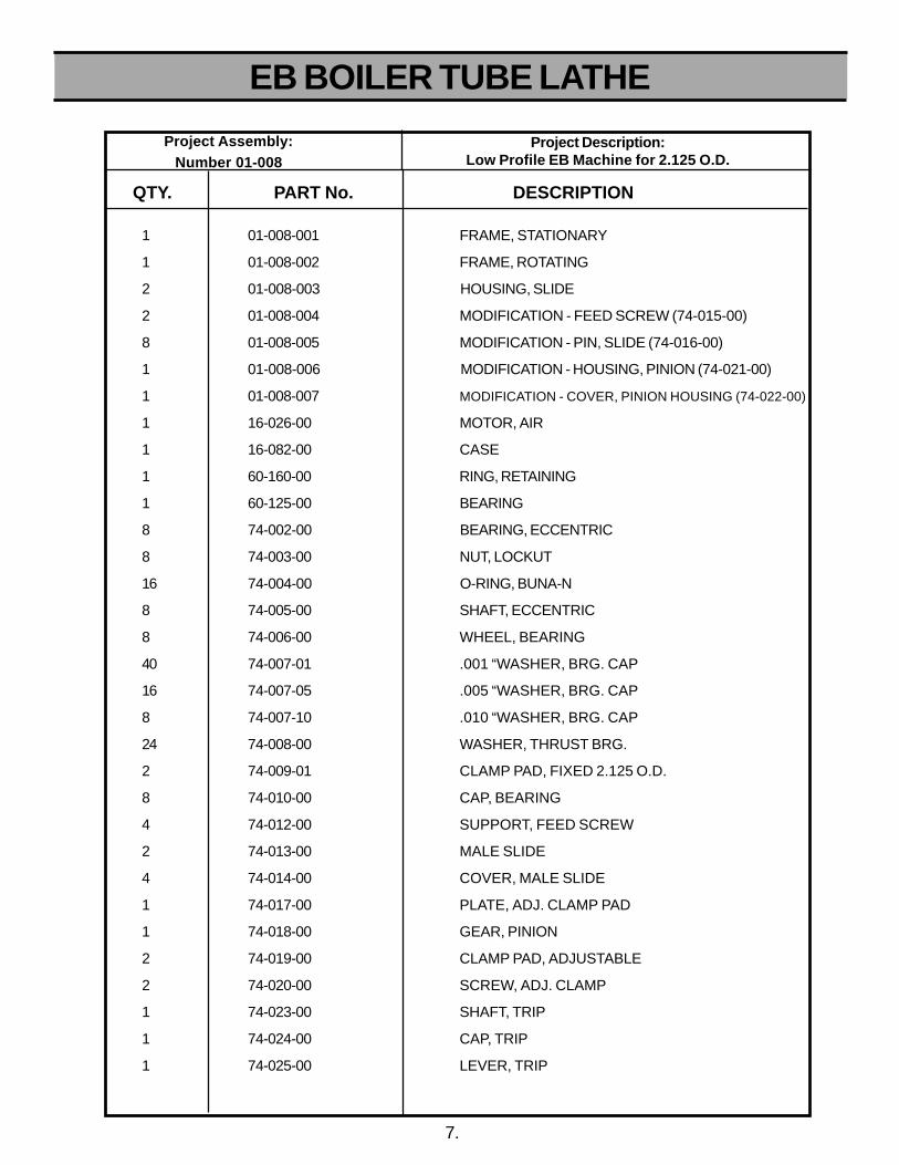
1 01-008-001 FRAME, STATIONARY
1 01-008-002 FRAME, ROTATING
2 01-008-003 HOUSING, SLIDE
2 01-008-004 MODIFICATION - FEED SCREW (74-015-00)
8 01-008-005 MODIFICATION - PIN, SLIDE (74-016-00)
1 01-008-006 MODIFICATION - HOUSING, PINION (74-021-00)
1 01-008-007 MODIFICATION - COVER, PINION HOUSING (74-022-00)
1 16-026-00 MOTOR, AIR
1 16-082-00 CASE
1 60-160-00 RING, RETAINING
1 60-125-00 BEARING
8 74-002-00 BEARING, ECCENTRIC
8 74-003-00 NUT, LOCKUT
16 74-004-00 O-RING, BUNA-N
8 74-005-00 SHAFT, ECCENTRIC
8 74-006-00 WHEEL, BEARING
40 74-007-01 .001 “WASHER, BRG. CAP
16 74-007-05 .005 “WASHER, BRG. CAP
8 74-007-10 .010 “WASHER, BRG. CAP
24 74-008-00 WASHER, THRUST BRG.
2 74-009-01 CLAMP PAD, FIXED 2.125 O.D.
8 74-010-00 CAP, BEARING
4 74-012-00 SUPPORT, FEED SCREW
2 74-013-00 MALE SLIDE
4 74-014-00 COVER, MALE SLIDE
1 74-017-00 PLATE, ADJ. CLAMP PAD
1 74-018-00 GEAR, PINION
2 74-019-00 CLAMP PAD, ADJUSTABLE
2 74-020-00 SCREW, ADJ. CLAMP
1 74-023-00 SHAFT, TRIP
1 74-024-00 CAP, TRIP
1 74-025-00 LEVER, TRIP
QTY. PART No. DESCRIPTION
Project Assembly: Number 01-008
Project Description:Low Profile EB Machine for 2.125 O.D.

EB BOILER TUBE LATHE
8.
QTY. PART No. DESCRIPTION
1 74-034-00 SPRING, DISC1 74-035-00 BEARING, NEEDLE1 74-036-00 RING, RETAINING1 73-037-00 SWIVEL, 1/4"1 74-038-00 FOAM, CASE1 73-040-00 AIR HOSE ASSM, 1/4" x 6'6 90-001-02 SHCS, 6-32 x 1/4"2 90-016-52 ROLL PIN, 3/32" x 1/4"2 90-020-03 SHCS, 8-32 x 3/8"1 90-026-07 DOWEL PIN, 1/8" x 3/4"
8 90-040-53 SHCS, 10-32 x 3/8"
2 90-040-58 SHCS, 10-32 x 7/8"
2 90-044-52 SSS, 10-32 x 1/4"
4 90-046-05 PIN, 3/16 x 1/2 DOWEL
1 90-046-07 DOWEL PIN, 3/16” x 3/4”
1 90-056-12 DOWEL PIN, 1/4” x 1-1/4”
6 90-050-06 SHCS, 1/4-20 x 5/8"
8 90-051-12 SHCS, 1/4-20 x 1-1/4
10 90-053-07 FHCS, 1/4-20 x 3/4"
2 90-054-02 SSS, 1/4-20 x 1/4"
8 90-056-17 DOWEL PIN, 1/4" x 1-3/4"
2 90-060-07 SHCS, 5/16-18 x 3/4"
2 90-060-17 SHCS, 5/16-18 x1-3/4"
2 90-069-10 H’COIL, 5/16-18 x .312
8 90-075-53 WASHER, 3/8" FLAT
1 90-096-12 DOWEL PIN, 1/2" x 1-1/4"
2 90-214-12 SSS, 3/4-10 x 1-1/4"
Project Description:Low Profile EB Machine for 2.125 O.D.
Project Assembly: Number 01-008
1 74-026-00 PIN, PULL6 74-027-00 PIN, ALIGNMENT16 73-030-01 BEARING, THRUST

EB BOILER TUBE LATHE
TROUBLE SHOOTING
SECTION VII

SECTION VII TROUBLE SHOOTING
Trouble Possible Cause Remedy
9.
EB BOILER TUBE LATHE
If a problem persists or is not listed in the above chart, ceaseoperation and consult the manufacturer for additional instructions.
Machine won't turn Power supply not on Check power supply
Improper bearing preload Refer to maintenance for proper Adjustment procedure.
Machine Runs Slowly Improper Speed Check air supply.
Tool slides do not feed Trip pin not engage Engage trip pins
Machine moves during cutting Loose clamp pads Tighten clamp pads
Machine chatters during cutting Speed control set too fast Slow down cutting speed.Loose clamp pads Tighten clamp pads
Poor cutting quality Tool bit is dull Replace tool bit.Improper tool installation Refer to tool bit installation instructions.
Lubricant necessary Refer to lubricant information in operation instructions.
14.
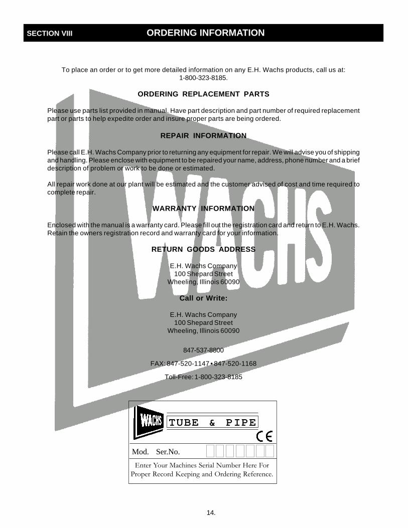
To place an order or to get more detailed information on any E.H. Wachs products, call us at:1-800-323-8185.
ORDERING REPLACEMENT PARTS
Please use parts list provided in manual. Have part description and part number of required replacementpart or parts to help expedite order and insure proper parts are being ordered.
REPAIR INFORMATION
Please call E.H. Wachs Company prior to returning any equipment for repair. We will advise you of shippingand handling. Please enclose with equipment to be repaired your name, address, phone number and a briefdescription of problem or work to be done or estimated.
All repair work done at our plant will be estimated and the customer advised of cost and time required tocomplete repair.
WARRANTY INFORMATION
Enclosed with the manual is a warranty card. Please fill out the registration card and return to E.H. Wachs.Retain the owners registration record and warranty card for your information.
RETURN GOODS ADDRESS
E.H. Wachs Company100 Shepard Street
Wheeling, Illinois 60090
Call or Write:
E.H. Wachs Company100 Shepard Street
Wheeling, Illinois 60090
847-537-8800
FAX: 847-520-1147 • 847-520-1168
Toll-Free: 1-800-323-8185
SECTION VIII ORDERING INFORMATION
������������ ��������������������������
���������������������������������������������
TUBE & PIPETUBE & PIPETUBE & PIPETUBE & PIPETUBE & PIPE
Mod. Ser.No.