eb-70
TRANSCRIPT
EB-70Ser vice Procedures
Part Number: 4501XXX


Contents
iii
Overview
1
Accessing the Fiery EB-70
3
Checking connections
4
LEDs, jumpers, and switches 5
Replacing the Fiery EB-70
6
Replacing Fiery EB-70 components
7
DIMMs 8
Battery 9
Hard disk drive 10
Restoring functionality after service
13
Using the Operation Panel
14
Status/Control features 15
Panel Display 15
Online and Offline display 16
Printing system pages from the Operation Panel
17
Printing the Configuration Page 17
Printing Demo Pages 17
Verifying connection to the network
19
Verifying the parallel port connection
20
System Software
22
System Software installation reminders 22
Installing System Software 23
Flash Upgrade
29
The troubleshooting process
33
Where problems occur 34
Before you go to the customer site 35
Preliminary on-site checkout 36
Checking connections 36
LED patterns
37
Startup diagnostics
38
Errors during installation of system software 40
Checking the network 41
Printing to the Fiery EB-70 41
Specifications
42
Hardware features 42
Networking and connectivity 42
User software 42
Safety and emissions compliance 42
Index

1
Overview
Overview
The Fiery EB-70 Print Controller embeds computer connectivity and highly efficient PostScript and PCL printing capability into black and white copiers. The Fiery EB-70 is designed for specific copier models (not described in this document).
The Fiery EB-70 is shipped with all necessary software already installed. This document describes how to service the Fiery EB-70 and reinstall system software, if necessary.
N
OTE
:
This document assumes that the Fiery EB-70 is already installed in the copier. Complete information on how to install and remove the Fiery EB-70 is included in other documentation.
Generally, the Fiery EB-70 does not require regular maintenance. Use these procedures to inspect, remove, reseat, or replace major hardware components and also to reinstall system software.
This document includes information on:
• Fiery EB-70 and Fiery EB-70 components
• DIMMs (page 8)
• Battery (page 9)
• Hard disk drive (page 10)
• System software (page 22)
• Flash upgrade (page 29)
See page 7 for an overview of Fiery EB-70 components.
Replacement parts for the Fiery EB-70 are available from your authorized service representative.
The Fiery EB-70 system software is installed on the hard disk drive at the factory. You will need to reinstall system software if you:
• Replace the hard disk drive
• Upgrade to a more recent version of the system software

2
Overview
F
IGURE
A
Fiery EB-70 exploded view
Key
1. Fiery EB-70 board
2. Battery
3. HDD cable
4. HDD
5. HDD bracket
6. DIMM
7. DIMM sockets
8. Connector to copier
9. RJ-45 network connector
10. LINK LED for network activity
11. Dual LEDs (DIAG-R and DIAG-G)
12. Service switch
13. Parallel port connector
NOTE: Faceplate not shown
6
7
5
4
3
2
1
8
910
11
1213

3
Accessing the Fiery EB-70
Accessing the Fiery EB-70
In order to service the Fiery EB-70, you need to power off the copier using the power switch on the left side of the copier (see Figure C below) and then remove the Fiery EB-70 from the copier. Two screws secure the Fiery EB-70’s faceplate to the copier. In order to access these screws and remove the Fiery EB-70 from the copier, you must first remove the copier’s back plastic panel. The metal Controller Box that encloses the Fiery EB-70 does not need to be removed in order to remove the Fiery EB-70 from the copier (see Figure B below). The Fiery EB-70 is removed with the faceplate attached. Complete information on how to install and remove the Fiery EB-70 is included in other documentation.
F
IGURE
B
Fiery EB-70 installed in the copier
F
IGURE
C
Copier power switch location
Copier back panel
Fiery EB-70installed in copier
Screws
Copier back panel with Fiery EB-70 installed
MAIN POWER
On
Stand by
Front of copier
4
Checking connections
Checking connections
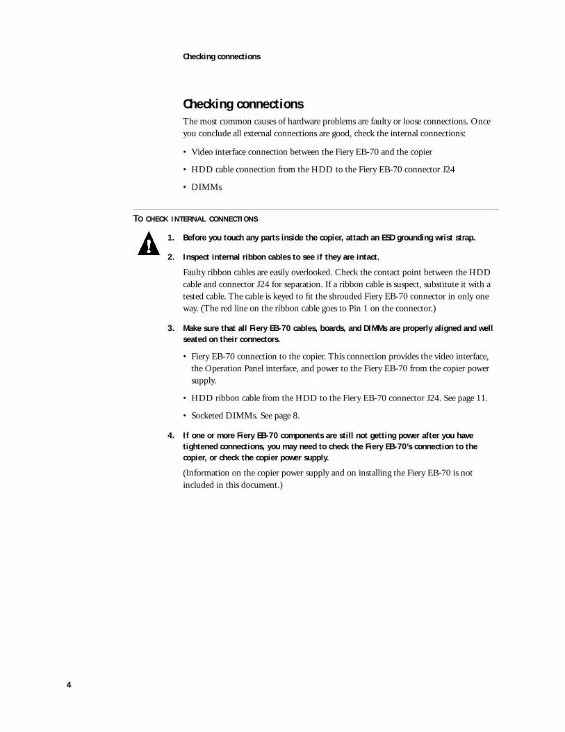
The most common causes of hardware problems are faulty or loose connections. Once you conclude all external connections are good, check the internal connections:
• Video interface connection between the Fiery EB-70 and the copier
• HDD cable connection from the HDD to the Fiery EB-70 connector J24
• DIMMs
T
O
CHECK
INTERNAL
CONNECTIONS
1. Before you touch any parts inside the copier, attach an ESD grounding wrist strap.
2. Inspect internal ribbon cables to see if they are intact.
Faulty ribbon cables are easily overlooked. Check the contact point between the HDD cable and connector J24 for separation. If a ribbon cable is suspect, substitute it with a tested cable. The cable is keyed to fit the shrouded Fiery EB-70 connector in only one way. (The red line on the ribbon cable goes to Pin 1 on the connector.)
3. Make sure that all Fiery EB-70 cables, boards, and DIMMs are properly aligned and well seated on their connectors.
• Fiery EB-70 connection to the copier. This connection provides the video interface, the Operation Panel interface, and power to the Fiery EB-70 from the copier power supply.
• HDD ribbon cable from the HDD to the Fiery EB-70 connector J24. See page 11.
• Socketed DIMMs. See page 8.
4. If one or more Fiery EB-70 components are still not getting power after you have tightened connections, you may need to check the Fiery EB-70’s connection to the copier, or check the copier power supply.
(Information on the copier power supply and on installing the Fiery EB-70 is not included in this document.)

5
Checking connections
LEDs, jumpers, and switches
The Fiery EB-70 has three activity indicators (LEDs) and one service switch accessible at the faceplate.
F
IGURE
D
LEDs and service switch
•
Network Activity LED and Dual LEDs
—Adjacent to the on-board RJ-45 connector, the green LED blinks to indicate network activity. This LED is labeled LINK on the Fiery EB-70 board.
Adjacent to the Activity LED are dual LEDs, one red and one green. These LEDs are labeled DIAG-R and DIAG-G on the Fiery EB-70 board. For more information, see “LED patterns” on page 37.
•
Service Switch
—A dual-rocker service switch is located on the Fiery EB-70 between the activity LEDs and the parallel port connector. With the copier powered off, you configure the service switch before performing service functions such as installing system software, formatting the HDD, or updating the Flash. The switch is set in the OFF position for normal operation, with both rockers to the right (away from the board). To perform service functions, power off the copier using the power switch on the left side of the copier and move the rockers to the ON position, with both rockers to the left (toward the board). To resume normal operation after completing service functions, power off the copier and return both rockers on the service switch to the OFF position (away from the board).
N
OTE
:
Some service functions may require you to enter a password through the numeric keypad on the Operation Panel. The password is
not
included in this document.
•
Jumpers
—No jumpers are installed in the Fiery EB-70’s standard configuration. A jumper (not provided) must be installed on two-pin jumper area J29 in order to upgrade the Flash. J29 is located on the Fiery EB-70 by the copier interface connector, adjacent to the Flash ROM at U15 (see Figure E on page 7). After the upgrade is finished, make sure to remove the jumper you installed. For more information, see “Flash Upgrade” on page 29.
Dual LEDs
Service switch
Network activity LED

6
Replacing the Fiery EB-70
Replacing the Fiery EB-70
When the Fiery EB-70 needs to be replaced, use the following procedure.
Make sure you attach an ESD grounding wrist strap and follow standard ESD (electrostatic discharge) precautions before following this procedure.
T
O
REPLACE
THE
F
IERY
EB-70
1. Power off the copier using the power switch on the left side of the copier (see Figure C on page 3).
2. Remove the Fiery EB-70 from the copier.
Two screws secure the Fiery EB-70’s faceplate to the copier. In order to access these screws and remove the Fiery EB-70 from the copier, you must first remove the copier’s back plastic panel. The metal Controller Box that encloses the Fiery EB-70 does not need to be removed in order to remove the Fiery EB-70 from the copier (see Figure B on page 3). The Fiery EB-70 is removed with the faceplate attached.
3. Remove the DIMMs from the Fiery EB-70 according to the procedure described on page 8.
4. Remove the HDD from the Fiery EB-70 according to the procedure described on page 10.
5. Unpack the new Fiery EB-70 and install the HDD and DIMMs you removed earlier onto the new board.
To reinstall the DIMMs, see page 8.
To reinstall the HDD, see page 12.
6. Reassemble the unit and verify functionality (see page 13).
7
Replacing Fiery EB-70 components
Replacing Fiery EB-70 components
N
OTE
:
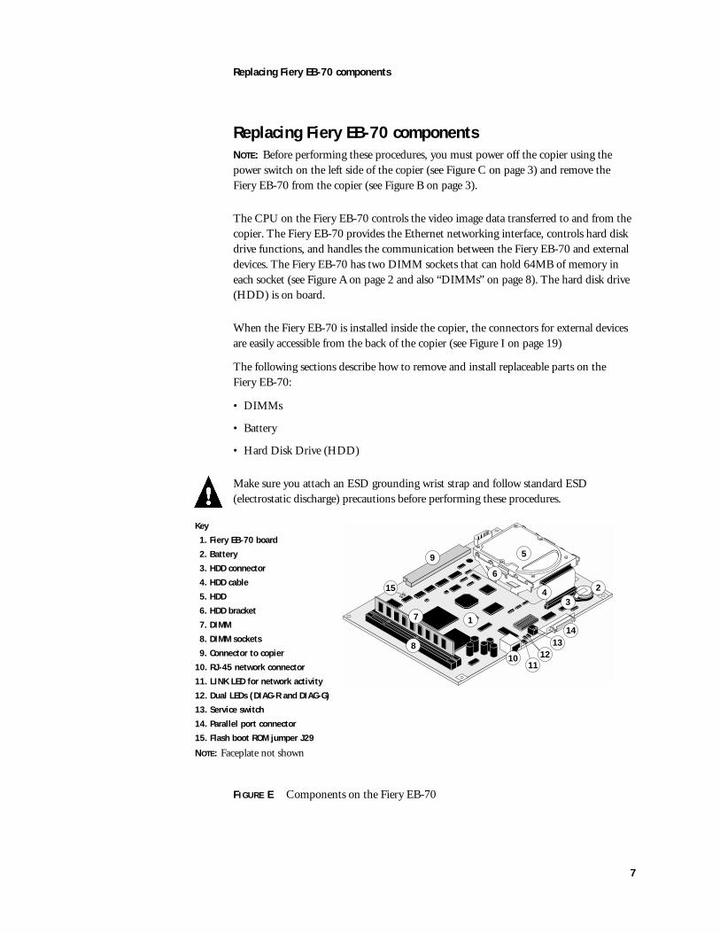
Before performing these procedures, you must power off the copier using the power switch on the left side of the copier (see Figure C on page 3) and remove the Fiery EB-70 from the copier (see Figure B on page 3).
The CPU on the Fiery EB-70 controls the video image data transferred to and from the copier. The Fiery EB-70 provides the Ethernet networking interface, controls hard disk drive functions, and handles the communication between the Fiery EB-70 and external devices. The Fiery EB-70 has two DIMM sockets that can hold 64MB of memory in each socket (see Figure A on page 2 and also “DIMMs” on page 8). The hard disk drive (HDD) is on board.
When the Fiery EB-70 is installed inside the copier, the connectors for external devices are easily accessible from the back of the copier (see Figure I on page 19)
The following sections describe how to remove and install replaceable parts on the Fiery EB-70:
• DIMMs
• Battery
• Hard Disk Drive (HDD)
Make sure you attach an ESD grounding wrist strap and follow standard ESD (electrostatic discharge) precautions before performing these procedures.
F
IGURE
E
Components on the Fiery EB-70
Key
1. Fiery EB-70 board
2. Battery
3. HDD connector
4. HDD cable
5. HDD
6. HDD bracket
7. DIMM
8. DIMM sockets
9. Connector to copier
10. RJ-45 network connector
11. LINK LED for network activity
12. Dual LEDs (DIAG-R and DIAG-G)
13. Service switch
14. Parallel port connector
15. Flash boot ROM jumper J29
NOTE: Faceplate not shown
24
5
6
7
8
1
9
1011
1213
14
3
15
8
Replacing Fiery EB-70 components
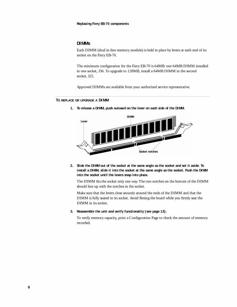
DIMMs
Each DIMM (dual in-line memory module) is held in place by levers at each end of its socket on the Fiery EB-70.
The minimum configuration for the Fiery EB-70 is 64MB: one 64MB DIMM installed in one socket, J36. To upgrade to 128MB, install a 64MB DIMM in the second socket, J25.
Approved DIMMs are available from your authorized service representative.
T
O
REPLACE
OR
UPGRADE
A
DIMM
1. To release a DIMM, push outward on the lever on each side of the DIMM.
2. Slide the DIMM out of the socket at the same angle as the socket and set it aside. To install a DIMM, slide it into the socket at the same angle as the socket. Push the DIMM into the socket until the levers snap into place.
The DIMM fits the socket only one way. The two notches on the bottom of the DIMM should line up with the notches in the socket.
Make sure that the levers close securely around the ends of the DIMM and that the DIMM is fully seated in its socket. Avoid flexing the board while you firmly seat the DIMM in its socket.
3. Reassemble the unit and verify functionality (see page 13).
To verify memory capacity, print a Configuration Page to check the amount of memory recorded.
Lever
Socket notches
DIMM

9
Replacing Fiery EB-70 components
Battery
The battery on the Fiery EB-70 is located at BT1, near the HDD. To replace it, use a 3V manganese dioxide lithium coin cell battery (Panasonic CR2032 or equivalent).
CAUTION:
There is danger of explosion if the battery is replaced with the incorrect type. Replace only with the same type recommended by the manufacturer. Dispose of used batteries according to the manufacturer's instructions.
ACHTUNG:
Es fbesteht Explosionsgefahr, wenn die Batterie durch eine Batterie falschen Typs ersetzt wird. Als Ersatz dürfen nur vom Hersteller empfohlene Batterien gleichen oder ähnlichen Typs verwendet werden.Verbrauchte Batterien müssen entsprechend den Anweisungen des Herstellers entsorgt werden.
ATTENTION:
Il y a risque d'explosion si la pile est remplacée par un modèle qui ne convient pas. Remplacez-la uniquement par le modèle recommandé par le constructeur. Débarrassez-vous des piles usées conformément aux instructions du constructeur.
T
O
REPLACE
THE
BATTERY
1. Locate the battery on the Fiery EB-70 (see Figure E on page 7).
2. Carefully lift up the clip that holds the battery.
A see-through isolation sheet is attached to the battery clip and covers the battery. Make sure this isolation sheet remains in place.
Use caution when lifting up the clip; excessive force could cause the clip to lose its tension.
3. Pull the battery out of its socket and release the clip.
4. To insert a new battery, slide the battery into the socket under the clip with the positive (+) side facing up.
Make sure the clip holds the battery securely in the socket.
5. Reassemble the unit and verify functionality (see page 13).
N
OTE
:
When you power on, let the Fiery EB-70 reach the Idle state, then power off and power on again to initialize the real-time clock.
ClipBattery
SocketSee-through isolation sheet
10
Replacing Fiery EB-70 components
Hard disk drive
The factory-installed hard disk drive (HDD) is formatted and loaded with all Fiery EB-70 software, including operating software, system software, network drivers, and printer fonts. The HDD is used to store spooled print jobs. Available disk space is listed on the Configuration Page.
If the hard disk drive needs to be replaced, you will need to install the system software on the new hard disk drive. (Replacement drives are shipped without Fiery EB-70 system software installed.)To replace the HDD, you need:
• The appropriate System Software CD
• The latest version of user software (for networked computers that will be printing to the Fiery EB-70)
See “System Software” on page 22 for instructions.
Proper handling
Handle the hard disk drive with care:
• Use proper ESD practices when grounding yourself and the Fiery EB-70.
• Keep magnets and magnetic-sensitive objects away from the HDD.
• Do not remove the screws on top of the HDD. Loosening these screws voids the warranty.
• Never drop, jar, or bump the HDD.
• Handle the HDD by its sides and avoid touching the printed circuit board.
• Allow the HDD to reach room temperature before installation.
Hard disk drive problems may be a result of the following:
• Loose or faulty connection
• Faulty hard disk drive
Before you decide that the hard disk drive needs to be replaced, make sure that the cable is connected properly.
Make sure you attach an ESD grounding wrist strap and follow standard ESD (electrostatic discharge) precautions before handling Fiery EB-70 components.
11
Replacing Fiery EB-70 components
T
O
REMOVE
THE
HDD
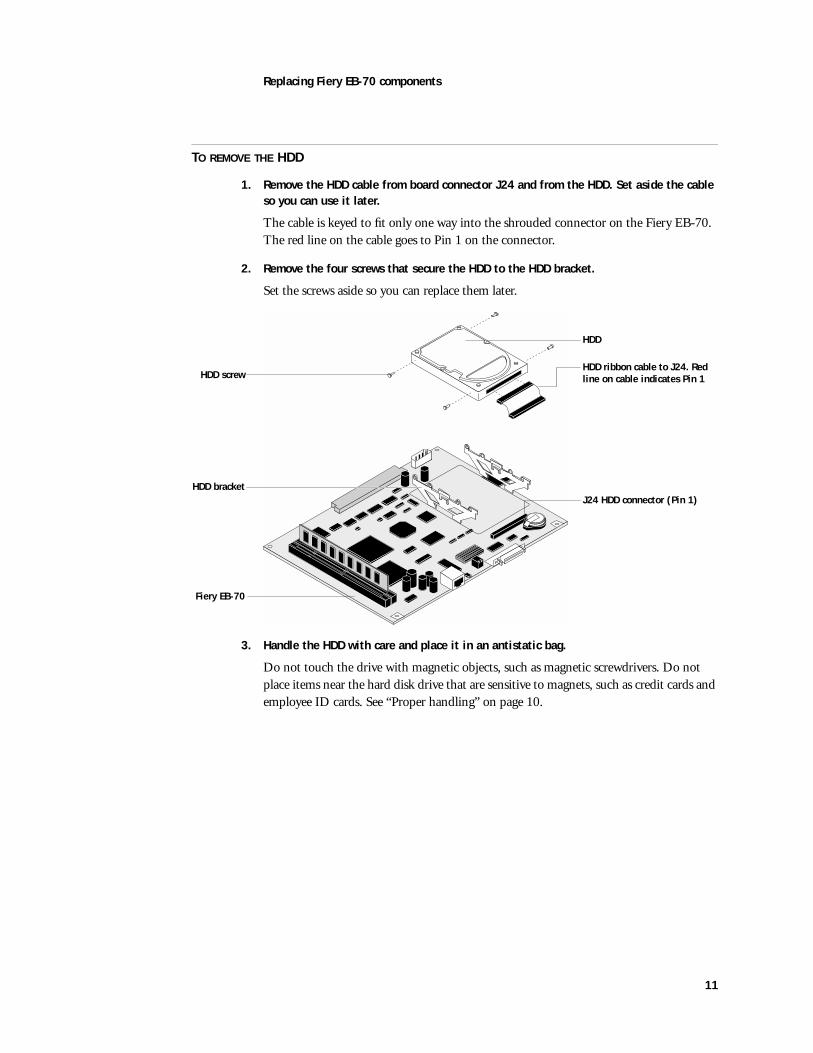
1. Remove the HDD cable from board connector J24 and from the HDD. Set aside the cable so you can use it later.
The cable is keyed to fit only one way into the shrouded connector on the Fiery EB-70. The red line on the cable goes to Pin 1 on the connector.
2. Remove the four screws that secure the HDD to the HDD bracket.
Set the screws aside so you can replace them later.
3. Handle the HDD with care and place it in an antistatic bag.
Do not touch the drive with magnetic objects, such as magnetic screwdrivers. Do not place items near the hard disk drive that are sensitive to magnets, such as credit cards and employee ID cards. See “Proper handling” on page 10.
HDD bracket
Fiery EB-70
HDD screw
HDD
HDD ribbon cable to J24. Red line on cable indicates Pin 1
J24 HDD connector (Pin 1)

12
Replacing Fiery EB-70 components
T
O
INSTALL
THE
HDD
Make sure you attach an ESD grounding wrist strap and follow standard ESD (electrostatic discharge) precautions before handling Fiery EB-70 components.
1. Handle the hard disk drive with care.
Do not touch it with magnetic objects or place any objects near it that are sensitive to magnets. See “Proper handling” on page 10.
2. Secure the HDD to the bracket on the board using the four screws you removed earlier. (See page 11)
3. Connect the HDD cable you removed earlier to the HDD and to board connector J24.
Make sure the cable remains firmly connected to J24.
4. Reassemble the unit and verify functionality (see page 13).
If the HDD or the Fiery EB-70 board is a replacement, you need to install system software as described on page 22.
13
Restoring functionality after service
Restoring functionality after service
To complete any service procedures performed on the Fiery EB-70, reinstall the Fiery EB-70 inside the copier and verify that it is working properly. To verify the installation, check the connection of the Fiery EB-70 first to the copier and then to the network and the parallel port.
T
O
REASSEMBLE
AND
VERIFY
THE
F
IERY
EB-70
1. Reseat any boards, cables, connectors, and other parts of the Fiery EB-70 that you loosened or removed during inspection or service.
2. Install the Fiery EB-70 in the copier and reassemble the copier as described in other documentation.
3. If you replaced the HDD or the Fiery EB-70 board, reinstall system software according to the procedure in “System Software” on page 22.
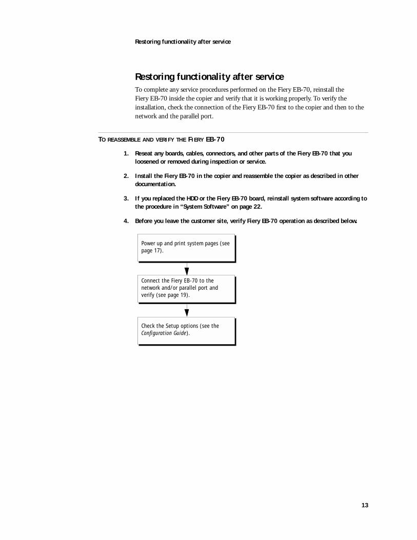
4. Before you leave the customer site, verify Fiery EB-70 operation as described below.
Power up and print system pages (see page 17).
Check the Setup options (see the Configuration Guide).
Connect the Fiery EB-70 to the network and/or parallel port and verify (see page 19).
14
Using the Operation Panel
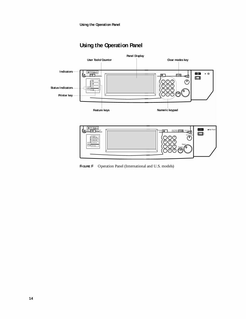
Using the Operation Panel
F
IGURE
F
Operation Panel (International and U.S. models)
ScreenContrast
User Tools/Counter
Sample Copy
InterruptProgram Clear Modes/Energy Saver
Clear/Stop
Start
Enter
On Main Power
CopyNew Job
Document ServerNew Job
Job List
Printer
Indicators
User Tools/Counter
Printer key
Numeric keypad
Clear modes key
Feature keys
Panel Display
Status Indicators
15
Using the Operation Panel
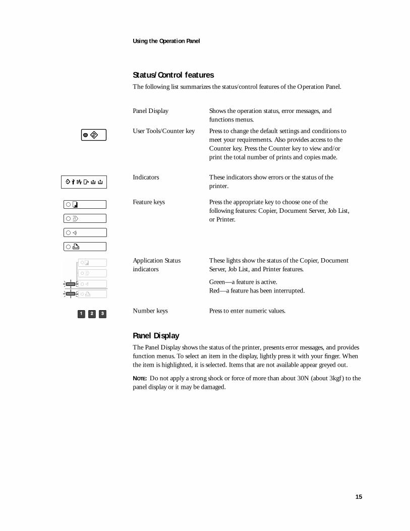
Status/Control features
The following list summarizes the status/control features of the Operation Panel.
Panel Display
The Panel Display shows the status of the printer, presents error messages, and provides function menus. To select an item in the display, lightly press it with your finger. When the item is highlighted, it is selected. Items that are not available appear greyed out.
N
OTE
:
Do not apply a strong shock or force of more than about 30N (about 3kgf ) to the panel display or it may be damaged.
Panel Display Shows the operation status, error messages, and functions menus.
User Tools/Counter key Press to change the default settings and conditions to meet your requirements. Also provides access to the Counter key. Press the Counter key to view and/or print the total number of prints and copies made.
Indicators These indicators show errors or the status of the printer.
Feature keys Press the appropriate key to choose one of the following features: Copier, Document Server, Job List, or Printer.
Application Status indicators
These lights show the status of the Copier, Document Server, Job List, and Printer features.
Green—a feature is active.Red—a feature has been interrupted.
Number keys Press to enter numeric values.
16
Using the Operation Panel
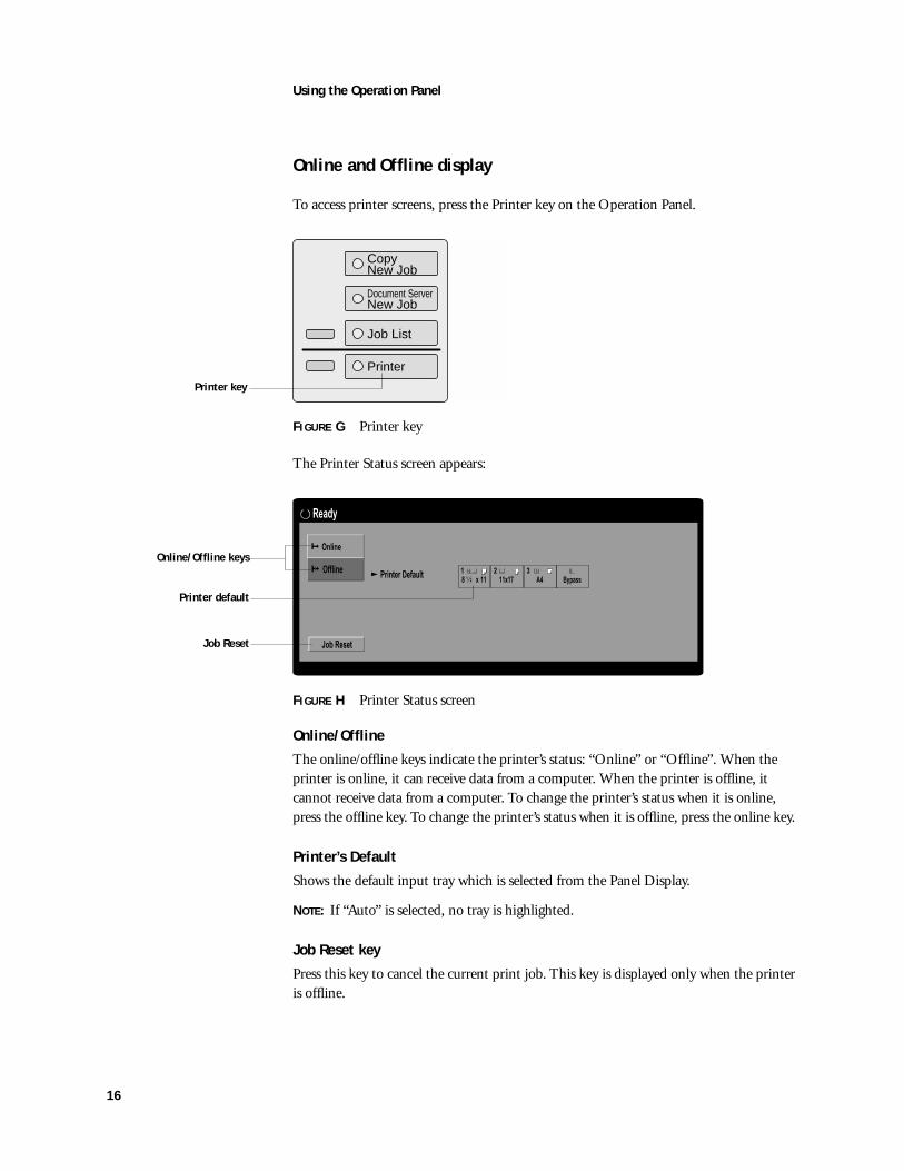
Online and Offline display
To access printer screens, press the Printer key on the Operation Panel.
F
IGURE
G
Printer key
The Printer Status screen appears:
F
IGURE
H
Printer Status screen
Online/Offline
The online/offline keys indicate the printer’s status: “Online” or “Offline”. When the printer is online, it can receive data from a computer. When the printer is offline, it cannot receive data from a computer. To change the printer’s status when it is online, press the offline key. To change the printer’s status when it is offline, press the online key.
Printer’s Default
Shows the default input tray which is selected from the Panel Display.
N
OTE
:
If “Auto” is selected, no tray is highlighted.
Job Reset key
Press this key to cancel the current print job. This key is displayed only when the printer is offline.
CopyNew Job
Document ServerNew Job
Job List
Printer
Printer key
Printer Default2
Online
Offline
Job Reset
1
8 x 111
2
11x173
A4 Bypass
Ready
Online/Offline keys
Printer default
Job Reset
17
Printing system pages from the Operation Panel
Printing system pages from the Operation Panel
It is recommended that you print the system pages before performing any service procedures. System pages can be printed from the Operation Panel via the List Print tab. These pages include the Configuration page, PCL and PostScript demo pages, PCL and PostScript font lists, Disk Directory List, and Minor Error Log.
Printing the Configuration Page
The Configuration Page lists all the settings in effect from the current Setup.
Before you perform any service procedure, you should print the Fiery EB-70 Configuration Page (if possible) so that you are prepared to return the settings to their former configuration, if necessary.
After the connection to the network is made, the network administrator can customize Setup options according to the network and user environment. Using the Configuration Page as a guide can help speed up this process. After making changes to the PostScript, Parallel, or Network tabs, the printer needs to be restarted in order for the settings to take effect and appear on the Configuration Page. For more information, see the
Configuration Guide.
Printing Demo Pages
Demo Pages are files that you print to verify that the Fiery EB-70 is functional and connected properly to the copier. Demo Pages reside on the Fiery EB-70 hard disk drive. Before connecting the Fiery EB-70 to the network, print each Demo Page, one for Postscript (PS) and one for PCL (Printer Control Language).
18
Printing system pages from the Operation Panel
T
O
THE
SYSTEM
PAGES
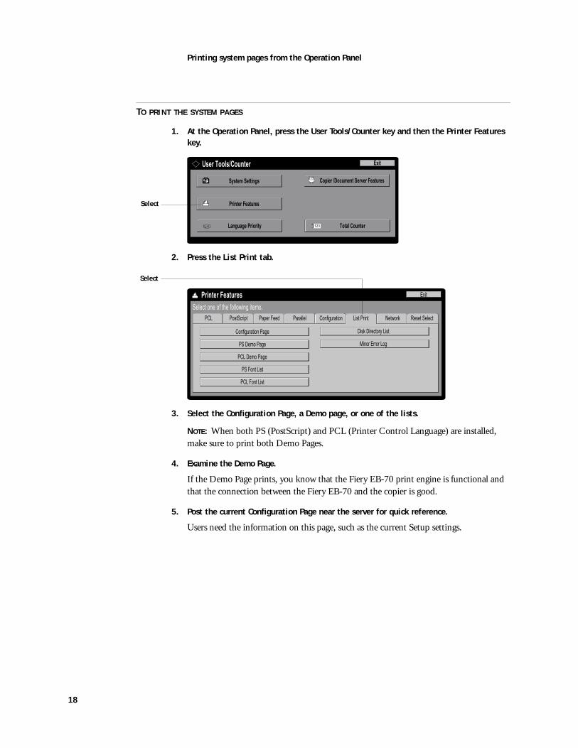
1. At the Operation Panel, press the User Tools/Counter key and then the Printer Features key.
2. Press the List Print tab.
3. Select the Configuration Page, a Demo page, or one of the lists.
NOTE: When both PS (PostScript) and PCL (Printer Control Language) are installed, make sure to print both Demo Pages.
4. Examine the Demo Page.
If the Demo Page prints, you know that the Fiery EB-70 print engine is functional and that the connection between the Fiery EB-70 and the copier is good.
5. Post the current Configuration Page near the server for quick reference.
Users need the information on this page, such as the current Setup settings.
ExitUser Tools/Counter
System Settings Copier /Document Server Features
Printer Features
Language Priority Total Counter1 2 3
Select
PostScript Paper Feed Parallel Network Reset SelectPCL Configuration
Exit
Select one of the following items.
List Print
Configuration Page
PS Demo Page
Disk Directory List
Minor Error Log
PCL Demo Page
PS Font List
PCL Font List
Printer Features
Select
19
Verifying connection to the network
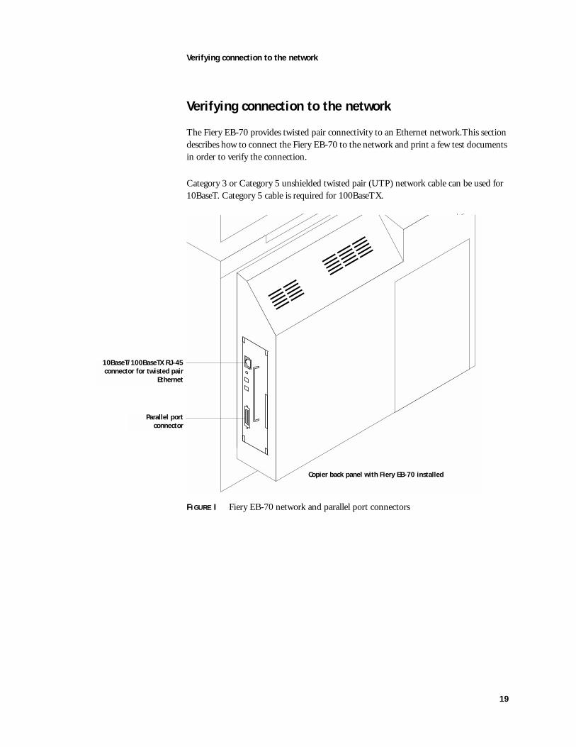
Verifying connection to the network
The Fiery EB-70 provides twisted pair connectivity to an Ethernet network.This section describes how to connect the Fiery EB-70 to the network and print a few test documents in order to verify the connection.
Category 3 or Category 5 unshielded twisted pair (UTP) network cable can be used for 10BaseT. Category 5 cable is required for 100BaseTX.
FIGURE I Fiery EB-70 network and parallel port connectors
Parallel portconnector
10BaseT/100BaseTX RJ-45connector for twisted pair
Ethernet
Copier back panel with Fiery EB-70 installed

20
Verifying the parallel port connection
TO CONNECT A TWISTED PAIR CABLE TO THE FIERY EB-70
Category 5 unshielded twisted pair (UTP) network cable must be used for 100BaseTX. The cable connects to the RJ-45 connector on the Fiery EB-70 (see Figure I on page 19).
1. Power off the copier using the power switch on the left side of the copier before connecting the Fiery EB-70 to any network device (see Figure C on page 3).
2. Connect the network cable to the RJ-45 connector on the Fiery EB-70 (see Figure I on page 19).
3. Configure Setup options.
It is the network administrator’s responsibility to configure Setup according to the network and user environment. Default settings in Setup may be adequate although they may not be optimal for the user’s environment. Refer the network administrator to the Configuration Guide for Setup information.
4. After configuring Setup options, verify the network connection.
Once the network connection has been made and the Fiery EB-70 has the correct Setup configuration and is Idle, the Fiery EB-70 should be available on the network.
The network administrator should perform any additional network Setup, verify the network connection, verify that the Fiery EB-70 appears in the list of printers, and print a few test documents from a networked computer that will use the Fiery EB-70. (See the Configuration Guide for more information.)
Verifying the parallel port connectionOn the Fiery EB-70, the parallel connector (female 36-pin mini-Centronics) provides a high-speed interface port for connecting directly to the parallel port of a PC. The parallel port can be used for installing system software (see page 22) and for printing documents.
The Fiery EB-70 can be connected to the network and to a parallel port device at the same time. See Figure I on page 19.
An IEEE 1284 bi-directional cable is required. One end of the cable requires a male IEEE 1284-C (36-pin mini-Centronics) connector for connecting to the Fiery EB-70.
NOTE: For optimal performance, use a short cable. Longer cables may cause erroneous operation.
21
Verifying the parallel port connection
TO CONNECT THE FIERY EB-70 TO A PC
NOTE: If the PC is being used to install system software, make sure it meets the minimum requirements specified in Getting Started.
1. Power off the copier using the power switch on the left side of the copier before connecting the Fiery EB-70 to a PC. (see Figure C on page 3)
2. Power off the PC.
3. Connect a parallel (Centronics) cable to the 36-pin mini Centronics connector on the Fiery EB-70 (see Figure I on page 19).
4. Connect the other end of the parallel cable to the parallel port of the PC.
If there is more than one parallel port connector on the back of the PC, ask the network administrator to indicate the preferred parallel port to use for the copier.
5. Power on the PC and the copier.
6. Configure Setup options.
It is the network administrator’s responsibility to configure Setup according to the network and user environment. Although default settings in Setup may be adequate, they may not be optimal for the user’s environment. Refer the network administrator to the Configuration Guide for Setup information.
7. After configuring Setup options, verify the parallel port connection.
Once the parallel port connection has been made and the Fiery EB-70 has the correct Setup configuration and is Idle, the network administrator should print a few test documents from the PC connected to the copier. See the Configuration Guide for more information.
22
System Software
System SoftwareThe Fiery EB-70 System Software CD includes one system software file to be installed over the parallel port of the Fiery EB-70.
Install system software when:
• You replace the Fiery EB-70 hard disk drive (HDD)
• You replace the Fiery EB-70 board
• You upgrade to a more recent version of the system software
System Software installation remindersKeep in mind the following when installing system software:
• Job Log—Formatting the HDD deletes the list of jobs in the Job Log and any jobs in the queues. The network administrator at the customer site can save a current list of jobs (not the actual job) from the Job Log using Fiery Spooler or WebSpooler.
• Fonts—Formatting the HDD deletes all fonts that the customer has installed on the Fiery EB-70. Only resident fonts will be restored during system software installation. Fiery Downloader can be used to reinstall additional fonts.
To determine which additional fonts were downloaded to the Fiery EB-70, print the Font List before you format the HDD and again after you complete the system software installation. Any fonts not listed after installation will need to be reinstalled. See the Printing Guide for more information.
• User Code Log and Network Settings—User code log information and network setup settings are not retained when the HDD is formatted and/or when system software is reinstalled. Network settings can be entered manually from the Operation Panel using the information provided on the Configuration Page. User code log information cannot be manually restored. To restore user code log information and network settings automatically, you must save the files before installing system software and then restore them after installing system software. This procedure and additional PC and software requirements are described in other documentation.
• Language—Screens for installing system software are always displayed in English, even if the copier is configured for another language.
• Compatibility—The latest user software must be installed onto all computers that print to the Fiery EB-70. Using incompatible versions of the system and user software may result in system problems.

23
System Software
Installing System SoftwareTo install system software using the parallel port on the Fiery EB-70, you need:
• A PC with Windows 95 or 98
• A CD-ROM drive built in or attached
• At least 400MB of disk space free
• Support for ECP mode on the parallel port
• IEEE 1284 bi-directional parallel cable (short)
One end of the parallel cable requires a male IEEE 1284-C (36-pin mini-Centronics) connector for connecting to the Fiery EB-70.
The PC will need to be configured so the parallel port mode in the BIOS is set to ECP. When you access the PC BIOS to set the parallel port mode to ECP, you may discover that ECP is the default mode, or you may discover that ECP mode is not supported at all. If ECP is not supported, you can either install an add-in board (not provided), use a different PC, or opt for a much slower installation using Compatibility Mode.
In addition to accessing the BIOS, setting up the PC also requires certain port and printer settings in Windows. Before you begin installing system software, follow the procedure for setting up the PC.
24
System Software
TO SET UP THE PC
1. Access the PC BIOS and make sure that Parallel Port Mode is set to ECP.
Power on the PC and immediately press the key indicated on your monitor for entering the BIOS (or a likely key if it is not indicated). Pressing a likely key repeatedly (ESC, DEL, F1, or a combination) may interrupt the starting of Windows and access the BIOS or give you directions for accessing the BIOS.
Once in the BIOS, you may have to scroll through several screens to reach the settings for the parallel port. After setting the Parallel Port Mode to ECP, save your changes and exit the BIOS.
2. Install the PostScript printer driver for the Fiery EB-70 from the User Software CD in the Windows subdirectory (for example, the win_9x directory).
This driver supports IEEE 1284 fast throughput over an ECP parallel port and allows you to configure all port and spool settings required for a successful installation. You may skip this step if a comparable printer driver is already installed on the PC. See Getting Started for directions on installing printer drivers.
3. In Windows, click the Start button, point to Settings, and click Printers.
4. Click the icon for the printer and choose Properties from the File menu.
5. Click the Details tab and make sure the box “Print to the following port:” reads exactly as follows: LPT 1: (ECP Printer Port).
If this box reads LPT 1: (Printer Port), then Parallel Port Mode is not set to ECP (see step 1). Compatibility mode will work but the installation will take much longer.
NOTE: In Windows NT or Windows 200 OS, printer port selection is made through the Port tab. Be aware that to select printer ports in these operating systems you may need Administrator access permissions.
6. Click Spool Settings and select “Spool print jobs so program finishes printing faster,” “Start printing after last page is spooled,” and, if it is not greyed out, “Disable bi-directional support for this printer”. Then click Apply and click OK.
NOTE: The “Start printing after first/last page is spooled” setting generally does not affect this procedure significantly. Choosing “last page” may result in a faster installation. If your PC is likely to spool the file very slowly, however, choose “Start printing after first page is spooled” in order to avoid disruption from a parallel port timeout.
Disabling Windows support for the bi-directional parallel port helps the system software installation to succeed.
7. Click Port Settings and ensure that “Spool MS-DOS print jobs” and “Check port state before printing” are checked. Click OK.
8. Click Apply, then OK to activate the settings and exit from the Printer Properties screen.
The PC is properly configured. Now prepare for the installation.
25
System Software
TO PREPARE FOR INSTALLATION USING THE PARALLEL PORT
1. Print the Configuration Page (if possible) to record the customer’s current configuration (see “Printing system pages from the Operation Panel” on page 17).
Setup settings are reset to the default configuration when system software is installed.
2. Print the Font List.
The Font List details what fonts are resident on the Fiery EB-70 HDD. Along with the fonts that are provided on the System Software CD, the customer may have installed additional fonts that will be deleted when the HDD is formatted.
3. Power off the copier using the power switch on the left side of the copier.
4. Enable the Fiery EB-70 for service by switching ON the service switch at the faceplate (see page 5).
5. Ensure that the PC is powered off.
6. Connect an IEEE 1284 cable to the LPT1 port on your PC (generally, a 25-pin D-type connector) and to the parallel port connector on the Fiery EB-70 (see Figure I on page 19).
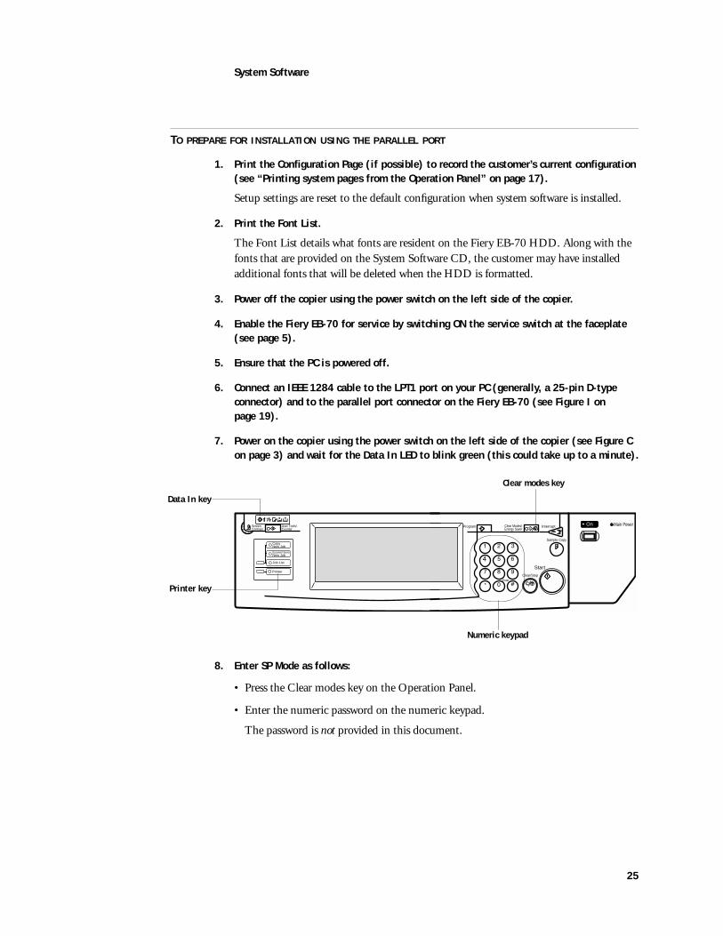
7. Power on the copier using the power switch on the left side of the copier (see Figure C on page 3) and wait for the Data In LED to blink green (this could take up to a minute).
8. Enter SP Mode as follows:
• Press the Clear modes key on the Operation Panel.
• Enter the numeric password on the numeric keypad.
The password is not provided in this document.
ScreenContrast
User Tools/Counter
Sample Copy
InterruptProgram Clear Modes/Energy Saver
Clear/Stop
Start
Enter
On Main Power
CopyNew Job
Document ServerNew Job
Job List
Printer
Printer key
Clear modes key
Numeric keypad
Data In key
26
System Software
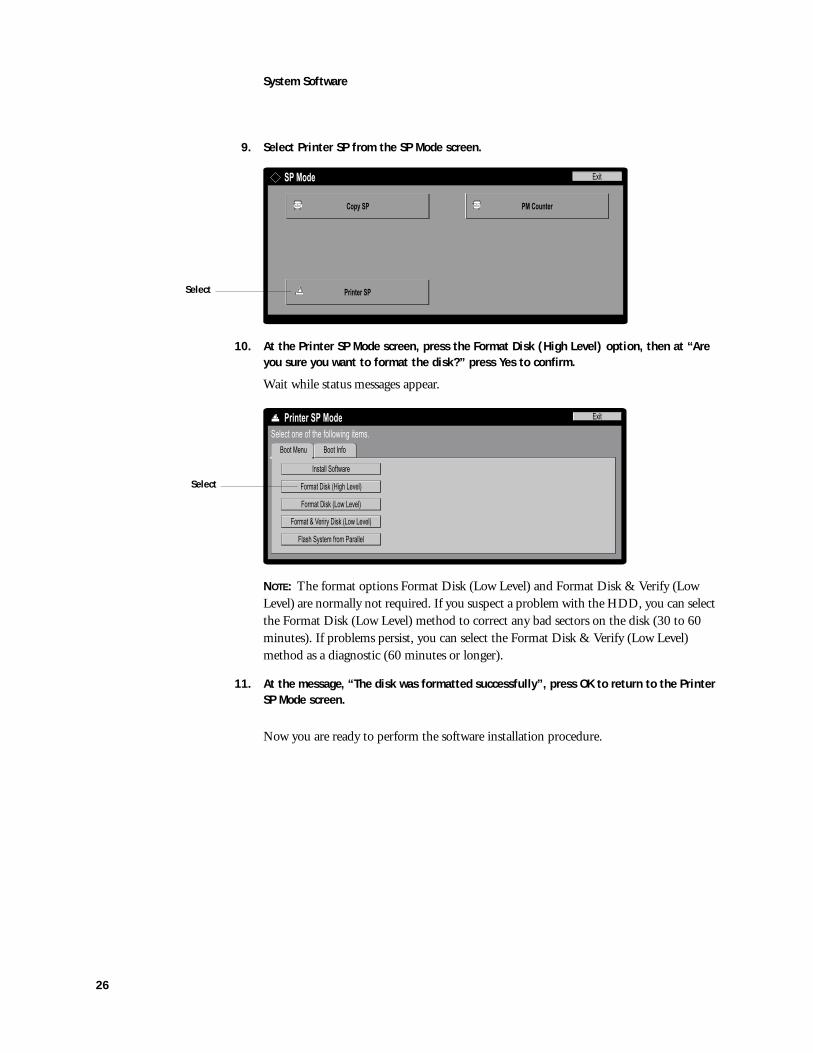
9. Select Printer SP from the SP Mode screen.
10. At the Printer SP Mode screen, press the Format Disk (High Level) option, then at “Are you sure you want to format the disk?” press Yes to confirm.
Wait while status messages appear.
NOTE: The format options Format Disk (Low Level) and Format Disk & Verify (Low Level) are normally not required. If you suspect a problem with the HDD, you can select the Format Disk (Low Level) method to correct any bad sectors on the disk (30 to 60 minutes). If problems persist, you can select the Format Disk & Verify (Low Level) method as a diagnostic (60 minutes or longer).
11. At the message, “The disk was formatted successfully”, press OK to return to the Printer SP Mode screen.
Now you are ready to perform the software installation procedure.
SP Mode
Printer SP
Exit
PM CounterCopy SP
Select
Exit
Select one of the following items.
Boot Info
Printer SP Mode
Install Software
Format Disk (High Level)
Format Disk (Low Level)
Format & Veriry Disk (Low Level)
Flash System from Parallel
Boot Menu
Select
27
System Software
TO INSTALL SYSTEM SOFTWARE
NOTE: This procedure assumes that you have performed the procedure “To prepare for installation using the parallel port” on page 25 which includes enabling the Fiery EB-70 for service and formatting the HDD.
1. Power on the PC and then insert the System Software CD into the CD-ROM drive.
2. In the Windows Start menu, point to Programs, and click MS-DOS Prompt to bring up an MS-DOS window.
Do not use the option to “Shut down and Restart Windows in DOS mode”.
3. At the MS-DOS prompt, change from the C:\ drive to the CD-ROM directory and do a dir command to display the filename of the software.
To find the correct letter for the CD-ROM drive, open the My Computer folder and read the drive letter associated with the CD-ROM icon.
The filename including the extension is displayed at the end of the MS-DOS line of text providing information about the file. If more than one file is in the directory, choose the filename most likely to be the system software installation file. The extension will be either .mm or .ssw.
4. At the Printer SP Mode screen on the Operation Panel, press the Install Software option but do not press Yes to confirm yet.
5. At the MS-DOS prompt, type the following command but do not press the enter (or return) key yet:
copy filename lpt1 /b
where filename refers to the file on the System Software CD that contains the system software, and /b specifies the binary option (not ASCII).
NOTE: Do not press the enter (or return) key yet.
6. At the Panel Display message “Are you sure you want to download new System Software?” press Yes.
7. When the Panel Display shows the message “Copying...”, press the enter (or return) key on the PC and then wait.
The status message “Downloading new System Software” shows progress from 0% to 100% in increments of 10%.
NOTE: Progress from 90% to 100% takes much longer than the previous increments. Make sure to wait until 100% is reached.
8. When the Panel Display shows the message “Software installation successful”, press OK then press Exit on the Printer SP Mode screen to return to the SP Mode screen.
9. With the SP Mode screen displayed on the Operation Panel, power off the copier using the power switch on the left side of the copier (see Figure C on page 3).
28
System Software
10. With the copier powered off, switch OFF the service switch at the Fiery EB-70 faceplate (see page 5).
11. Remove the parallel cable from the copier and the PC.
12. On the PC, exit MS-DOS and remove the System Software CD from the CD-ROM drive.
13. Power on the copier using the power switch on the left side of the copier and allow the Fiery EB-70 to reach Ready.
You may need to press the Printer key on the Operation Panel to view the Printer screen.
14. To select the alternate language, press the User/Tools key on the Operation Panel and then press the Language Selection button in the Panel Display.
15. Reenter the customer’s settings from the Configuration Page that you printed earlier.
Bypass settings not included on the Configuration Page if it is more appropriate for the site administrator to set them. Some settings you must do from the Operation Panel and some you must do from Web Setup. See the Configuration Guide for information.

29
Flash Upgrade
Flash UpgradeNOTE: Perform a Flash upgrade only if you have been informed that a Flash upgrade is necessary and you have received a Flash upgrade file.
The following procedures describe how to check the Flash version and how to upgrade the Flash if required.
TO CHECK THE FLASH VERSION
1. Enable the Fiery EB-70 for service (see page 5) and access the Printer SP Mode screen (see page 25).
2. At the Printer SP Mode screen, press the Boot Info tab.
3. Verify the version of the Boot Block and the Main Block. If the version displayed is earlier than the version of the Flash upgrade file provided, you will need to perform the procedure “To install the Flash upgrade” on page 30.
4. If no more service functions are required, press Exit on the Printer SP Mode screen, then power off the copier using the power switch on the left side of the copier and switch off the service switch at the Fiery EB-70 faceplate to resume normal operation (see page 5).
If necessary, install the Flash upgrade.
Before performing the procedure “To install the Flash upgrade”:
• Obtain a PC that meets the requirements described on page 23.
Exit
Select one of the following items.
Boot Info
Printer SP Mode
Install Software
Format Disk (High Level)
Format Disk (Low Level)
Format & Veriry Disk (Low Level)
Flash System from Parallel
Boot MenuSelect
Boot Menu
Exit
Select one of the following items.
Boot Info
Printer SP Mode
Boot Block Version xxx
Boot Block Date mm/dd/yy
xxxMain Block Version
mm/dd/yyMain Block Date

30
Flash Upgrade
• Configure the PC for installing a file over the parallel port as described on page 24.
• Enable the Fiery EB-70 for service by configuring the service switch at the Fiery EB-70 faceplate as described on page 5.
• Install a jumper on two-pin jumper area J29 as described on page 5.
• Attach the PC to the parallel port of the Fiery EB-70 as described on page 20 and page 21.
NOTE: If the Setup configuration has been changed from the default, or if additional fonts have been installed, print the Configuration Page and the Font List before beginning the following procedure. After performing the Flash upgrade use these pages to reconfigure the system if necessary.
This procedure assumes that you have the Flash upgrade file available for installation.
TO INSTALL THE FLASH UPGRADE
1. With the copier powered off, enable the Fiery EB-70 for service and install a jumper on two-pin jumper area J29 (see page 5).
2. After connecting the PC to the Fiery EB-70 parallel port, power on the copier and PC.
3. If the Flash upgrade file is on CD or floppy disk, insert the media into the PC. In the Windows Start menu, point to Programs, click MS-DOS Prompt, and then change to the directory with the Flash upgrade file.
4. At the MS-DOS prompt, type the following command but do not press the enter key yet:
copy filename lpt1 /b
where filename refers to the Flash upgrade file, and /b specifies the binary option (not ASCII).
5. Access the Printer SP Mode screen (see page 25).
6. At the Printer SP Mode screen, press the option “Flash System from Parallel” and press Yes to confirm.
7. Press the enter (or return) key on the PC and then wait while the copier displays the messages “Please wait” and “Copying...”
Exit
Select one of the following items.
Boot Info
Printer SP Mode
Install Software
Format Disk (High Level)
Format Disk (Low Level)
Format & Veriry Disk (Low Level)
Flash System from Parallel
Boot Menu
Select

31
Flash Upgrade
8. Wait during the copier screen message “Upgrading Flash.”
Do not turn off the copier during this message. Otherwise, the Fiery EB-70 will be damaged.
9. At the message “System Flash Download successful. Power machine off and then on to restart.” press OK to return to the Printer SP Mode screen.
10. Power off the copier using the power switch on the left side of the copier, wait a few moments, then power on the copier (see Figure C on page 3).
11. Let the system continue its startup sequence until it reaches Ready.
12. On the PC, exit MS-DOS and shutdown Windows.
13. From the PC, remove the CD or floppy disk containing the Flash upgrade file.
14. Power off the PC, then power off the copier using the power switch on the left side of the copier.
15. Remove the parallel cable connecting the PC and the Fiery EB-70.
16. On the Fiery EB-70, remove the jumper you installed on jumper area J29.
17. Power on the copier and check the Flash version to make sure the upgrade was successful (see page 29).
18. Power off the copier and switch OFF the service switch at the Fiery EB-70 faceplate to resume normal operation (see page 5).

33
The troubleshooting process
This following sections identify the source of common problems that may occur with the Fiery EB-70 and suggests ways of correcting them.
The troubleshooting processThe troubleshooting process is designed to eliminate the most obvious causes of failure before progressing to more complex issues. “Where problems occur” on page 34 gives an overview of the Fiery EB-70 components and indicates areas most likely to require troubleshooting.
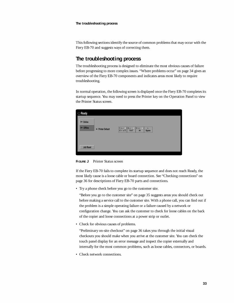
In normal operation, the following screen is displayed once the Fiery EB-70 completes its startup sequence. You may need to press the Printer key on the Operation Panel to view the Printer Status screen.
FIGURE J Printer Status screen
If the Fiery EB-70 fails to complete its startup sequence and does not reach Ready, the most likely cause is a loose cable or board connection. See “Checking connections” on page 36 for descriptions of Fiery EB-70 parts and connections.
• Try a phone check before you go to the customer site.
“Before you go to the customer site” on page 35 suggests areas you should check out before making a service call to the customer site. With a phone call, you can find out if the problem is a simple operating failure or a failure caused by a network or configuration change. You can ask the customer to check for loose cables on the back of the copier and loose connections at a power strip or outlet.
• Check for obvious causes of problems.
“Preliminary on-site checkout” on page 36 takes you through the initial visual checkouts you should make when you arrive at the customer site. You can check the touch panel display for an error message and inspect the copier externally and internally for the most common problems, such as loose cables, connectors, or boards.
• Check network connections.
Printer Default2
Online
Offline
Job Reset
1
8 x 111
2
11x173
A4 Bypass
Ready
34
The troubleshooting process
“Checking the network” on page 41 provides guidelines for checking the network connections between the copier and the computers to which it is connected as well as information on several printing problems.
Where problems occur
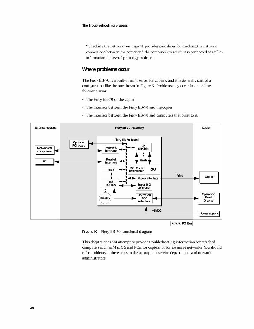
The Fiery EB-70 is a built-in print server for copiers, and it is generally part of a configuration like the one shown in Figure K. Problems may occur in one of the following areas:
• The Fiery EB-70 or the copier
• The interface between the Fiery EB-70 and the copier
• The interface between the Fiery EB-70 and computers that print to it.
FIGURE K Fiery EB-70 functional diagram
This chapter does not attempt to provide troubleshooting information for attached computers such as Mac OS and PCs, for copiers, or for extensive networks. You should refer problems in these areas to the appropriate service departments and network administrators.
Fiery EB-70 Board
Power supply
External devices CopierFiery EB-70 Assembly
+5VDC
CPU
Network interface
OperationPanel
Display
Memory &Interpreter
CopierPrint
DX RIPChip
Flash
Networked computers
PC
RTC/PCI-ISA
Parallel interface
HDD
Battery
Super I/Ocontroller
OperationPanel
interface
Video interface
PCI Bus
Optional PCI board
35
The troubleshooting process
Before you go to the customer siteBefore you make a service call to a customer site, talk to the customer on the phone, and check out the following items:
1. Does the copier work?
If the copier works, but the user cannot print the Fiery EB-70 Demo Page, have the customer check for any error messages displayed on the touch panel display. If an error has occurred on the Fiery EB-70 that probably requires a service call.
2. Is the failure caused by a simple operating problem?
• Is there a printing problem?
• Does the Fiery EB-70 Demo Page fail to print?
• Does the Fiery EB-70 fail to respond to a print command?
• Does printing seem to take a long time?
• Is print quality poor?
• Does the Fiery EB-70 fail to appear in the list of printers?
• Has the customer noted any error messages on the touch panel display?
If the answer to any of these questions is yes, refer the customer to the Troubleshooting chapters in the Job Management Guide and the Printing Guide.
If the customer has followed the corrective actions in the Job Management Guide and Printing Guide and has failed to solve the problem, be prepared to make a service call. Keep a log of the failures and messages the customer has observed.
3. Has the customer made any network changes?
If network changes have occurred, request that the customer’s network administrator verify the Fiery EB-70 network requirements.
4. Is the user having printing problems with a particular image file?
If there are problems with files from particular applications, the user may be more successful using different print settings.
If your telephone call fails to clear up the problem, proceed to the next phase, the preliminary on-site checkout.
36
The troubleshooting process
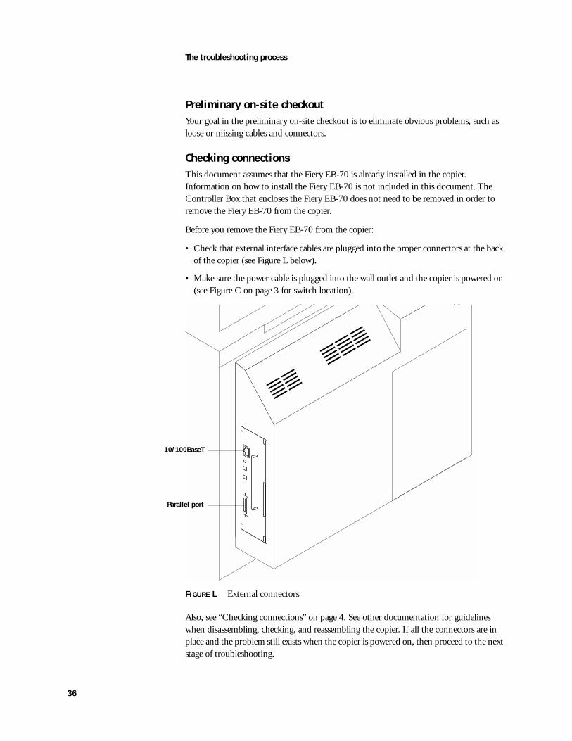
Preliminary on-site checkoutYour goal in the preliminary on-site checkout is to eliminate obvious problems, such as loose or missing cables and connectors.
Checking connectionsThis document assumes that the Fiery EB-70 is already installed in the copier. Information on how to install the Fiery EB-70 is not included in this document. The Controller Box that encloses the Fiery EB-70 does not need to be removed in order to remove the Fiery EB-70 from the copier.
Before you remove the Fiery EB-70 from the copier:
• Check that external interface cables are plugged into the proper connectors at the back of the copier (see Figure L below).
• Make sure the power cable is plugged into the wall outlet and the copier is powered on (see Figure C on page 3 for switch location).
FIGURE L External connectors
Also, see “Checking connections” on page 4. See other documentation for guidelines when disassembling, checking, and reassembling the copier. If all the connectors are in place and the problem still exists when the copier is powered on, then proceed to the next stage of troubleshooting.
10/100BaseT
Parallel port
37
LED patterns
TO CHECK INTERNAL CONNECTIONS
1. Before you touch any parts inside the copier, attach an ESD grounding wrist strap.
2. Inspect internal ribbon cables to see if they are intact.
Faulty ribbon cables are easily overlooked. Check the contact point between the cable and the connector to ensure that they have not separated. If a ribbon cable is suspect, substitute it with a tested cable.
3. Make sure that all Fiery EB-70 cables, boards, and DIMMs are properly aligned and well seated on their connectors.
• PCI connection to copier. This connection provides the video interface, the Operation Panel interface, and power to the Fiery EB-70 from the copier power supply.
• HDD ribbon cable from the HDD to the Fiery EB-70 connector J24. See the procedure on page 11.
• Socketed DIMMs at J36 and/or J25. See the procedure on page 8.
4. After tightening connections, if one or more Fiery EB-70 components are still not getting power, you may need to check the copier power supply.
LED patternsThe dual LEDs visible from the faceplate provide Fiery EB-70 status and troubleshooting information.
• Green LED is ON when the copier is powered on. Failure to turn on means the Fiery EB-70 or the connection of the Fiery EB-70 to the copier is faulty.
• If DIMMs fail or are missing, a few minutes after the copier is powered on, the red LED blinks 5 times, pauses, and repeats
• During startup diagnostics, the red LED is ON. It remains ON if a test fails.

38
Startup diagnostics
Startup diagnosticsStartup diagnostics are completed within a few seconds. They are performed in the background every time you power on the copier. If an error occurs, startup diagnostics are interrupted and the Functional Problems screen is displayed, presenting the error code of the test that failed (see Figure M below).
If the error still occurs after powering the machine off and on, look up the error code in Table A on page 39 and perform the suggested actions to resolve the error.
The error must be resolved before the Fiery EB-70 can be used for printing.
FIGURE M Sample Functional Problems screen
The following table lists the codes for each of the Startup diagnostics and the suggested actions for resolving the error.
Turn main power switch off then on. If the error appears again,
call service.
Functional Problems
SC2004: 00001001
Call Tel 00-000-00000

39
Startup diagnostics
TABLE A Possible errors during Startup diagnostics
Service code Test name Area tested on Fiery EB-70 Suggested action
SC2000 Functional Problem: RTC Error
00000700 RTC Self Realtime Clock chip • Replace the battery on the Fiery EB-70 (see “Battery” on page 9).
• If the problem persists, replace the Fiery EB-70.00000710 RTC R/W Reg
00000720 RTC Stop
00000730 RTC Start
00000740 RTC Set
SC2001 Functional Problem: I2C Error
00001100 I2C EEPROM I2C EEPROM • Replace the Fiery EB-70.
SC2002 Functional Problem: Ethernet Slave Register
00000401 ENET SLV REG Ethernet controller chipDIMMs
• Check DIMMs.
• Have network administrator verify network.
• If the problem persists, you may need to replace the Fiery EB-70.
SC2003 Functional Problem: Ethernet INIT
SC2004 Functional Problem: IDE Error
00001001 IDE Chip HDD chip • Replace the Fiery EB-70.
00001002 IDE Drive/Cable
HDD drive or cable • Check connections.
• Replace the cable.
• Replace the HDD.
00001003 IDE Internal HDD • Replace the HDD.
SC2005 Functional Problem: Memory DIMM Error
00000300 DIMM Init DIMM • See suggested actions for SC2006 below.
SC2006 Functional Problem: Memory Address Error
00000301 Error memory DIMM • Reseat the DIMM in its socket.
• If the problem persists, insert the DIMM into the other socket. If the DIMM fails in that location, replace it.
• Replace the Fiery EB-70.
00000302 Error Memory Ground
00000310 DRAM SIMM
00000320 DRAM Slot
00000330 DRAM Config
00000340 DRAM Write
00000350 DRAM 20MB
00000360 DRAM Size
40
Startup diagnostics
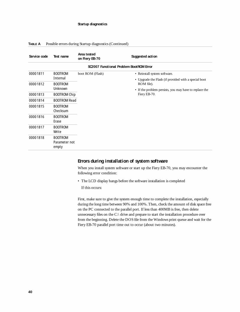
Errors during installation of system softwareWhen you install system software or start up the Fiery EB-70, you may encounter the following error condition:
• The LCD display hangs before the software installation is completed
If this occurs:
First, make sure to give the system enough time to complete the installation, especially during the long time between 90% and 100%. Then, check the amount of disk space free on the PC connected to the parallel port. If less than 400MB is free, then delete unnecessary files on the C:\ drive and prepare to start the installation procedure over from the beginning. Delete the DOS file from the Windows print queue and wait for the Fiery EB-70 parallel port time out to occur (about two minutes).
SC2007 Functional Problem BootROM Error
00001811 BOOTROM Internal
boot ROM (Flash) • Reinstall system software.
• Upgrade the Flash (if provided with a special boot ROM file).
• If the problem persists, you may have to replace the Fiery EB-70.
00001812 BOOTROM Unknown
00001813 BOOTROM Chip
00001814 BOOTROM Read
00001815 BOOTROM Checksum
00001816 BOOTROM Erase
00001817 BOOTROM Write
00001818 BOOTROM Parameter not empty
TABLE A Possible errors during Startup diagnostics (Continued)
Service code Test name Area tested on Fiery EB-70 Suggested action
41
Startup diagnostics
Checking the networkPrinting problems may arise if the network hardware or software is not set up properly or does not match network settings on the Fiery EB-70. Problems may also arise when printing from a specific application or printing a particular file.
Most of these problems show up as printing problems and do not necessarily indicate a Fiery EB-70 malfunction. The customer’s network administrator can eliminate many printing problems without requiring you to make a service call. The network administrator deals with:
• Copier error conditions
• Network connection problems that result in the copier not appearing in list of printers on the customer’s computers
NOTE: If the copier does not appear in the list of printers on the network, there may be another device on the network with the same IP address
• Conflicting network settings in Setup and on the customer’s computers.
• Printing problems caused by inappropriate Setup options
• Application-specific printing errors caused by missing or incorrectly installed printer description files
Printing to the Fiery EB-70If the customer can print a Fiery EB-70 Demo Page but cannot print a job from a computer on the network, you may have to make a service call. However, first make sure the network administrator has done the following:
• Checked all components of the network including cables, connectors, terminators, network adapter boards, and network drivers.
• Activated the network and used it to communicate with other printers.
• Checked the corrective actions listed in the Troubleshooting chapters of the Job Management Guide and the Printing Guide.
• Confirmed that the applicable network settings in Setup (such as AppleTalk zone, IP address, Subnet mask, and Gateway address) match the settings used in the network.
When you make a service call, check the Fiery EB-70 faceplate at the back of the copier to make sure that the network connection is in place. Print quality problems are difficult to trace. Before you try to troubleshoot print quality problems, print a Demo Page to make sure that the copier does not need servicing or adjusting. Also, make sure the correct paper is being used in the copier.
NOTE: EPS file generation is not completely standardized among applications. Some users may encounter problems while printing certain EPS files.
42
Specifications
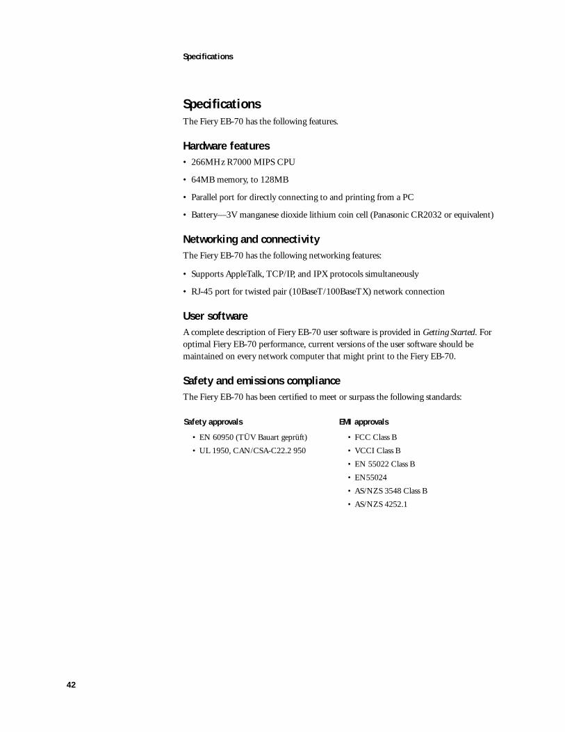
SpecificationsThe Fiery EB-70 has the following features.
Hardware features• 266MHz R7000 MIPS CPU
• 64MB memory, to 128MB
• Parallel port for directly connecting to and printing from a PC
• Battery—3V manganese dioxide lithium coin cell (Panasonic CR2032 or equivalent)
Networking and connectivityThe Fiery EB-70 has the following networking features:
• Supports AppleTalk, TCP/IP, and IPX protocols simultaneously
• RJ-45 port for twisted pair (10BaseT/100BaseTX) network connection
User softwareA complete description of Fiery EB-70 user software is provided in Getting Started. For optimal Fiery EB-70 performance, current versions of the user software should be maintained on every network computer that might print to the Fiery EB-70.
Safety and emissions complianceThe Fiery EB-70 has been certified to meet or surpass the following standards:
Safety approvals EMI approvals
• EN 60950 (TÜV Bauart geprüft) • FCC Class B
• UL 1950, CAN/CSA-C22.2 950 • VCCI Class B
• EN 55022 Class B
• EN55024
• AS/NZS 3548 Class B
• AS/NZS 4252.1

I-1
Numerics10/100BaseT 19, 20, 36, 41, 42
Aactivity indicators 5
Bbattery 9, 42BIOS 23boot ROM
functional problem 40upgrade 29version 29
Ccables
Centronics (parallel port) 20checking connections 4, 19, 20, 36, 37,
41, 42HDD 12
CDsystem software 22, 23
Centronicscable 20
checking connectionscables 4, 11, 12, 20, 33, 34, 36, 41, 42DIMMS 4, 8, 37HDD 4, 11, 12, 37internal 4, 11, 12, 34network 19, 20, 33, 34, 36, 41, 42
Configuration page 17printing from Operation Panel 17
DDemo Pages 17diagnostics
boot ROM 40ENET SLV REG 39I2C EEPROM 39Real Time Clock 39RTC R/W Reg 39RTC Self 39startup 39
DIMMsconfigurations 8removal and replacement 8
disk space 23
EECP mode 23EMI approvals 42ENET SLV REG 39errors
at startup 39ESD precautions 6, 7Ethernet 19, 20, 36, 41, 42
Fflash
upgrade 5, 29version 29
Hhard disk drive
connector (J24) 4, 11proper handling 10removal 11, 12system software 10
II2C EEPROM 39internal 37internal connections 19
JJ24 HDD connector 4J25 DIMM socket 8J29 Flash upgrade jumper 5J36 DIMM socket 8
LLEDs 5
Nnetwork connections
checking 19, 20, 33, 34, 36, 41, 42twisted pair (10/100BaseT) 19, 20, 41,
42network settings 22
Oon-board
battery 2, 9DIMMs 2, 8HDD 2, 5
Index
I-2
Index
Pparallel port 19, 20, 36PC, connecting 20precautions 6, 7printing
Configuration page from Operation Panel 17
Demo Pages 17problems 41
Rribbon cable
checking connections 4, 37RTC R/W Reg 39RTC Self 39
Ssafety approvals 42screens 17startup diagnostics
boot ROM 40ENET SLV REG 39I2C EEPROM 39Real Time Clock 39RTC R/W Reg 39RTC Self 39tests 39
switches 5system pages 17system software, installing 22, 23
Ttwisted pair (10/100BaseT) 20
UU5 5user code log 22