easy evaluation and development of mmwave systems with
TRANSCRIPT

MMWAVE-SDK deep dive Easy evaluation and development of mmWave systems with software development kit
Nitin Sakhuja - Industrial mmWave Radar Applications
1

MMWAVE-SDK deep dive TI's MMWAVE-SDK (MilliMeter Wave Software Development Kit) is a unified software platform for the TI mmWave
Sensing Portfolio, providing easy setup and fast out-of-the-box access to evaluation and development.
This training provides an overview of the MMWAVE-SDK 3.x architecture and the various building blocks such as
Data Processing Units (DPUs) and Data Processing Chains(DPCs). It also provides a deeper look into the
components with software execution flows accompanied with source code references from the MMWAVE-SDK Out
of Box Demo point cloud processing chain.
We also present some example applications where the Out of box point cloud detection chain is extended to
develop more complex mmWave applications such as Long Range People Detection and Tracking Demo, Traffic
Monitoring Demo and Area Scanner Demo.
2
What you’ll learn: • TI MMWAVE-SDK architecture and it’s various building blocks such as DPCs and DPUs
• Understand DPM, DPC and DPU execution flows e.g. initialization and runtime operation using source code references
• Developing custom components to extend the out of box processing chain and available examples.
Agenda
• MMWAVE-SDK – Architecture overview
– Data path design
• Data path deep dive – Initialization
– Configuration
– Execution (Runtime view)
• DPUs and DPCs in MMWAVE-SDK 3.x – DPUs: Range, Static-Clutter removal, Doppler, CFAR-CA and AoA
– DPCs: HWA and DSP based object detection chains
• Software development and debugging – Development resources
– MMWAVE-SDK debugging
• Extending SDK architecture for advanced applications – Considerations for developing custom DPUs and DPCs
– Custom DPUs and DPCs in Industrial Toolbox
– Demo: Long Range People Tracking and, Traffic Monitoring
– Demo: Area Scanner and, Automated Doors and Gates
3

MMWAVE-SDK - Architecture Overview
4
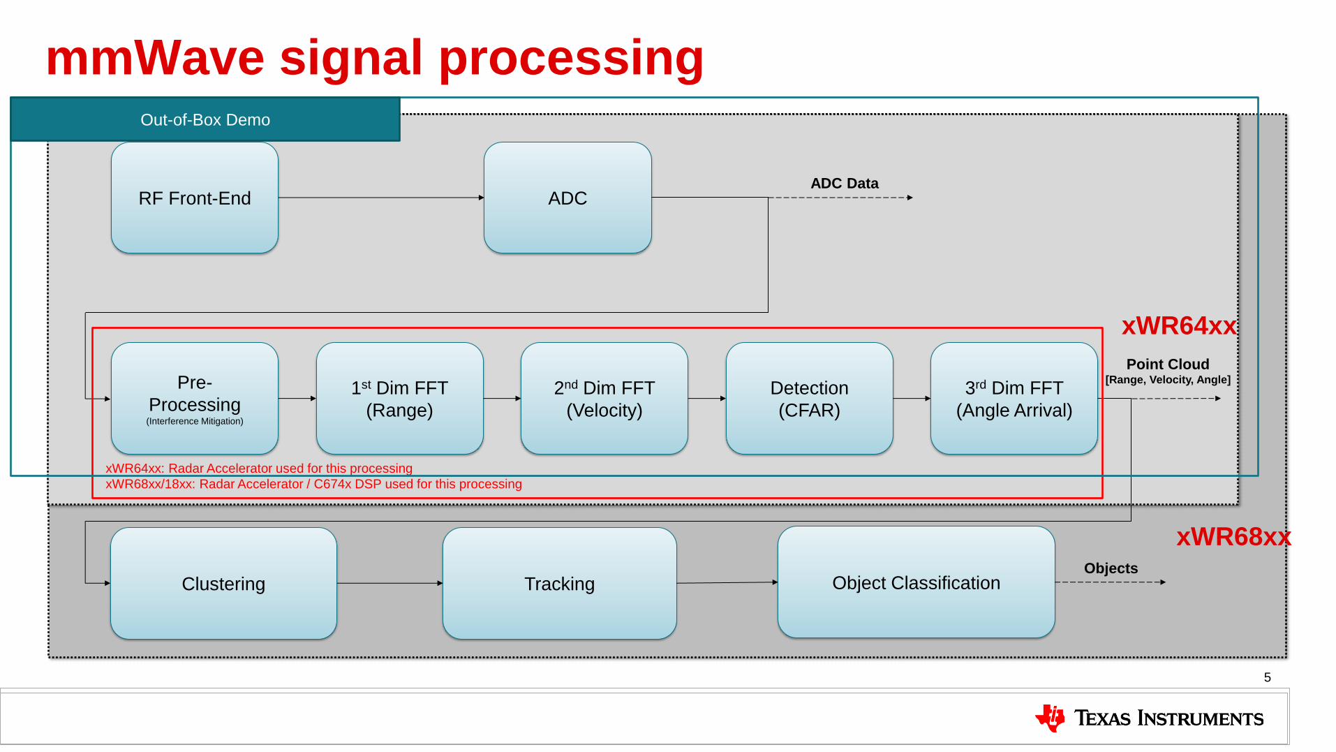
mmWave signal processing
5
RF Front-End ADC ADC Data
xWR64xx
xWR68xx
Pre-
Processing (Interference Mitigation)
1st Dim FFT
(Range)
2nd Dim FFT
(Velocity)
Detection
(CFAR)
3rd Dim FFT
(Angle Arrival)
Point Cloud [Range, Velocity, Angle]
Clustering Tracking Object Classification Objects
xWR64xx: Radar Accelerator used for this processing
xWR68xx/18xx: Radar Accelerator / C674x DSP used for this processing
Out-of-Box Demo

mmWave SDK contents • Building blocks
– RTOS, Drivers, and RadarSS firmware – Scalable data processing blocks and chains to work on HWA or DSP – Layered / API based Radar analog front end (AFE) programming – Pre-built software blocks and chains for basic FMCW Radar signal processing – Catalog of mmWave signal processing algorithms optimized for C674x DSPs including
tracker – Package for high-security (HS) devices to enable programming encryption keys and
encrypt/authenticate program binaries
• Demonstrations and examples – TI RTOS based – Out of box demo with easy configurability via TI Cloud-based or offline GUI – Representation of point cloud and benchmarking data from demo via GUI
• Documentation – Associated tools: Code Composer Studio, TI-RTOS, Uniflash – Available at http://www.ti.com/tool/MMWAVE-SDK

mmWave SDK architecture
7
Datapath Processing Chain
TI mmWave Application Demo
Analog front-end Processor (DSP and R4) and peripherals BSS
Firmware Boot ROM
mmWave Link mmWave
Library
RTOS Drivers + OSAL
IPC
mmWave
API
TI-RTOS OS, Drivers, Algorithms
mmWave APIs
Point Cloud
DataPath
Interface Range Doppler CFAR AoA
DataPath
EDMA Datapath
Manager
Main highlights:
- Foundational components for SOC enablement – RTOS, Drivers, mmWaveLink, mmWaveLib
- RF Front-end completely abstracted using mmWaveLink
- mmWave API simplifies device integration of mmWaveLink
- Data path layer is an abstraction over existing driver APIs in the data flow
- Separation of data processing units and chain from the application
- Simpler application that does the instantiation of the Datapath layer

MMWAVE-SDK – Datapath Design
8
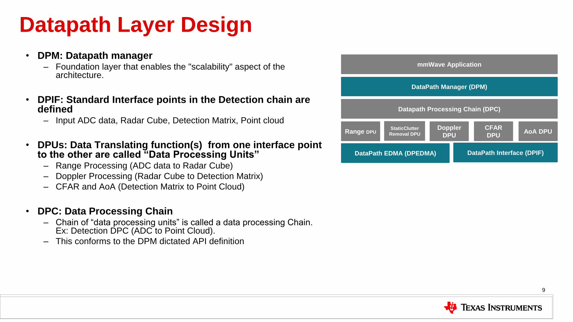
Datapath Layer Design
• DPM: Datapath manager – Foundation layer that enables the "scalability" aspect of the
architecture.
• DPIF: Standard Interface points in the Detection chain are defined
– Input ADC data, Radar Cube, Detection Matrix, Point cloud
• DPUs: Data Translating function(s) from one interface point to the other are called “Data Processing Units”
– Range Processing (ADC data to Radar Cube)
– Doppler Processing (Radar Cube to Detection Matrix)
– CFAR and AoA (Detection Matrix to Point Cloud)
• DPC: Data Processing Chain – Chain of “data processing units” is called a data processing Chain.
Ex: Detection DPC (ADC to Point Cloud).
– This conforms to the DPM dictated API definition
9
Datapath Processing Chain (DPC)
Range DPU Doppler
DPU
CFAR
DPU AoA DPU
DataPath Interface (DPIF) DataPath EDMA (DPEDMA)
DataPath Manager (DPM)
mmWave Application
StaticClutter
Removal DPU
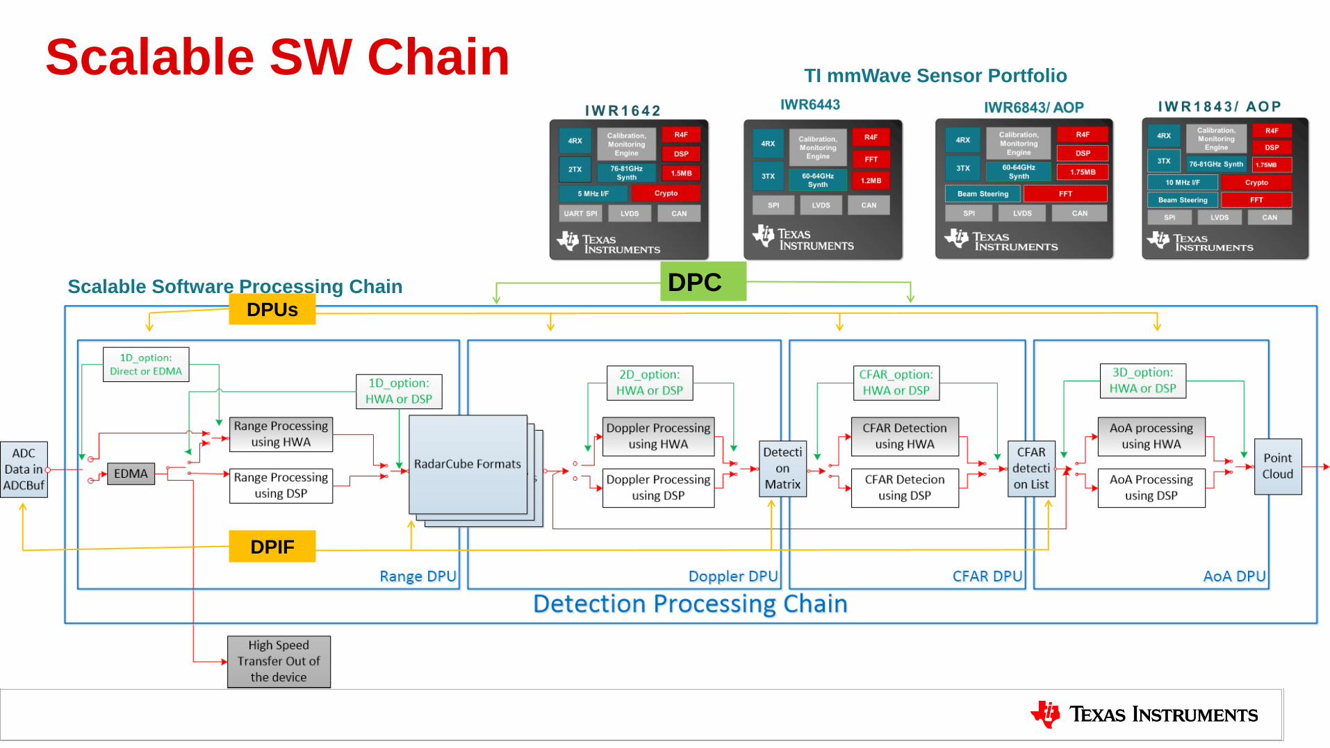
Scalable SW Chain
10
TI mmWave Sensor Portfolio
Scalable Software Processing Chain
DPIF
DPUs
DPC

Typical call flow (1/2)
11
DPM MSS Application DPUs Drivers DPC
DPM Init DPC Init
DPU#1 Init
DPU#2 Init
DPU#n Init
HWA/EDMA Init
DPM Ioctl
(Config#1) DPC Ioctl (Config#1)
DPU#1 Config
DPU#2 Config
DPU#n Config
DPM Ioctl
(Config#2) DPC Ioctl (Config#2) DPU#1 Config
DPU#2 Config
DPU#n Config
EDMA/HWA Config
EDMA/HWA Config
DPM Report Callback
(NOTIFY_DPC_IOCTL)
DPM Report Callback
(NOTIFY_DPC_IOCTL)
Config#1 and Config#2 are shown as
examples here on how a config can be
split into multiple shorrter structures as
needed by a DPC. It is not mandatory to
split into two. On the contrary, config can
be split into even more smaller structures.

Typical call flow (2/2)
12
DPM MSS Application DPUs Drivers DPC
DPM Start
DPC Start
DPU#1 Process
DPU#2 Process
DPU#n Process
H/W Frame
Event
H/W Chirp
Events
<point cloud results>
DPM Report
(NOTIFY_DPC
_STARTED)
DPM Stop
DPC Stop DPM Report
(NOTIFY_DPC
_STOPPED)

Data path deep dive
13

DPM: Datapath Manager
• Modular SW Architecture which provides an abstraction between the “Datapath Processing Chain” and the customer application.
• Main task context which encapsulates the execution of DPC and DPUs
• Application code instantiates DPM at start-up and registers a DPC.
• Provides a well-defined API
• Exposed to the application to interface with the DPM
• Exposed to the “Data processing chain” developers to be able to write their own code.
• Messaging mechanism
• Send/Receive Configuration
• Extends to Multiple-Thread/Core
• Synchronized execution (No critical section required)
• Response Mechanism with error code passing
• Reporting mechanism which allows applications to be notified about the status of the DPM/Datapath Processing Chain.
14
Core Layer
Datapath Chain
Management Message
Application Developers
Data Processing Chain
Developers
Datapath Manager

DPM Initialization • Application code creates
and initializes a DPM
instance using the DPM_init
function
• Application also creates a
DPM task
15
Source: MMWAVE-SDK HTML documentation
C:\ti\mmwave_sdk_03_xx_xx_xx\docs\mmwave_sdk_module_documentatio
n.html
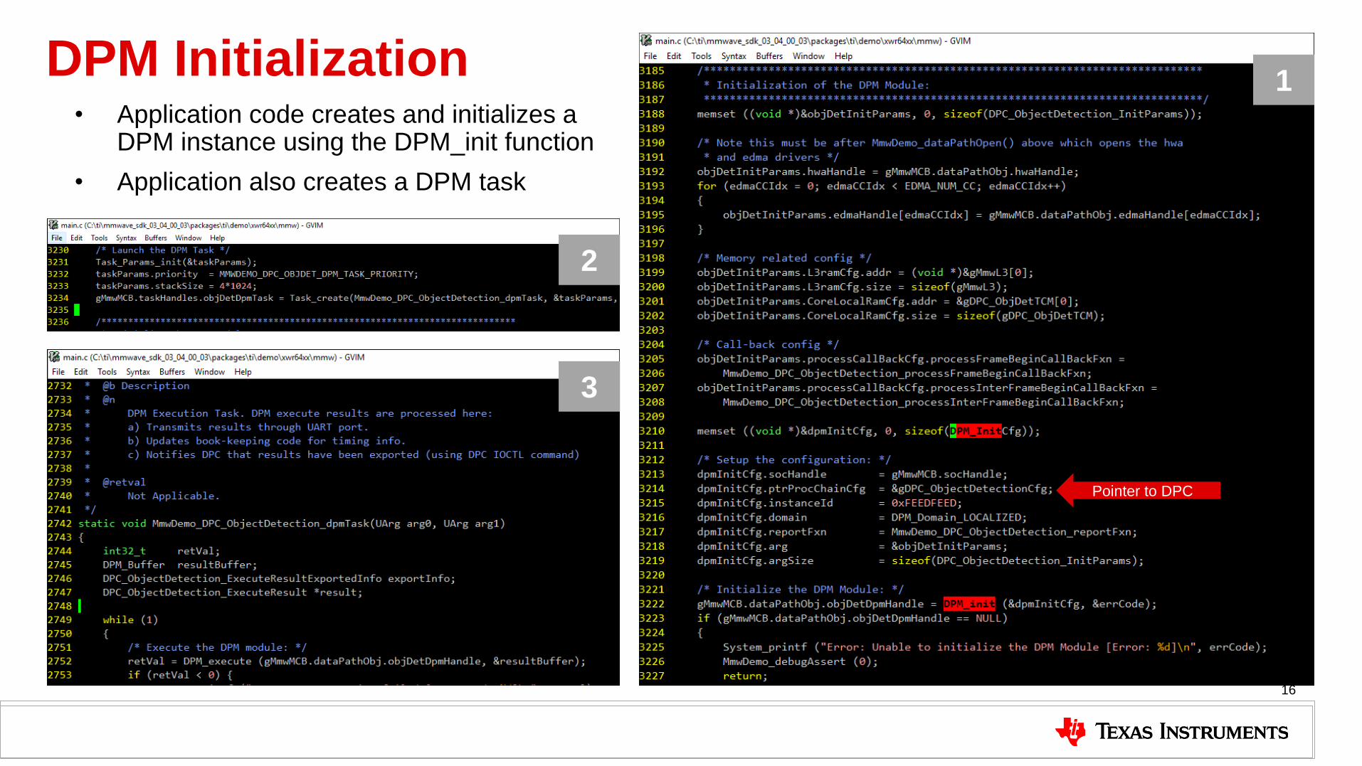
DPM Initialization • Application code creates and initializes a
DPM instance using the DPM_init function
• Application also creates a DPM task
16
1
2
3
Pointer to DPC

• DPC_xxx_init
• DPC_xxx_execute
• DPC_xxx_ioctl
• DPC_xxx_start
• DPC_xxx_injectData
• DPC_xxx_stop
• DPC_xxx_deinit
DPC_xxx_APIs
• DPC_xxx_cbChirpAvailable
• DPC_xxx_cbFrameStart
DPC_xxx_Callbacks
DPC: Data Processing Chain
17
• All external DPC APIs starts with DPC_. DPC
unique name follows next (follows coding
guidelines).
• DPC_ObjectDetection_Init
• External Mandatory APIs follows the prototype
defined by the “Datapath Manager”
• DPCs have flexibility in defining their own
content within the individual structure
• DPC that is split between MSS and DSS will
expose two set of APIs - one for MSS and one
for DSS. Depending on the functionality split
between the two domains, not all APIs need to
be implemented on the two domains
For more details, refer to docs
folder in each of the DPCs

DPC Initialization • Application registers the DPC with
DPM during DPM creation.
• Application calls DPM init which calls the DPC’s registered init function
• Application calls DPM_ioctl with different message types
• DPM_ioctl invokes the DPC’s registered ioctl function with: • Pre-start common config
message (common to all sub-frames) and
• Sub-frame specific Pre-start config messages.
• DPC handles the messages in the ioctl function and performs the corresponding configuration.
18
Source: MMWAVE-SDK HTML documentation
C:\ti\mmwave_sdk_03_xx_xx_xx\docs\mmwave_sdk_module_documentatio
n.html

DPC Initialization • Application registers the DPC with DPM during
DPM creation.
• Application calls DPM init which calls the DPC’s registered init function
• Application calls DPM_ioctl with different message types
• DPM_ioctl internally invokes the DPC’s registered ioctl function and passes the message to it
• DPC handles the message in the ioctl function and performs the corresponding configuration
• Refer to the call flow below
19
1
2

DPC Configuration • Application registers the DPC with DPM during
DPM creation.
• Application calls DPM init which calls the DPC’s registered init function
• Application calls DPM_ioctl with different message types (i.e. commands)
• DPM_ioctl internally invokes the DPC’s registered ioctl function and passes the message to it
• DPC handles the message in the ioctl function and performs the corresponding configuration
• Refer to the call flow below
20

DPC Configuration (continued) • Application registers the DPC with DPM during
DPM creation.
• Application calls DPM init which calls the DPC’s registered init function
• Application calls DPM_ioctl with different message types
• DPM_ioctl internally invokes the DPC’s registered ioctl function and passes the message to it
• DPC handles the message in the ioctl function and performs the corresponding configuration
• Refer to the call flow below
21
5
6
DPU: Data Processing Units
22
•DPU_xxx_InitParams_t
•errCode
•Handle
DPU_xxx_init
•DPU_Handle
•DPU_xxx_Config_t
•H/W Resources (EDMA, HWA, I/O buffer pointers, Scratch buffer pointers)
•Frame/Sub-frame DPU Static Config (Ex: Num ADC Samples, Chirps/Frame, ADCBuf Config, Data Interface Desc)
•Frame/Sub-frame DPU Dynamic Config (Ex: DC Range Calibration)
•errCode
DPU_xxx_config
•DPU_Handle
•DPU_xxx_OutParams_t
•DPU_xxx_Stats_t
•DPU optional specific Params (Ex: isLastChirp)
•errCode
DPU_xxx_process
•DPU_Handle
•cmd
•args
•argSize
•errCode
DPU_xxx_control
•DPU_handle
•errCode
DPU_xxx_deinit
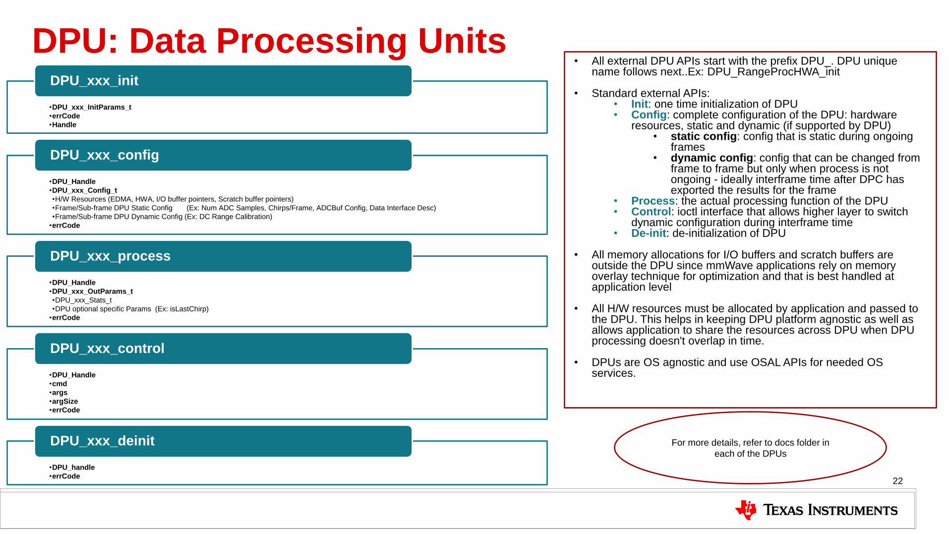
• All external DPU APIs start with the prefix DPU_. DPU unique name follows next..Ex: DPU_RangeProcHWA_init
• Standard external APIs:
• Init: one time initialization of DPU • Config: complete configuration of the DPU: hardware
resources, static and dynamic (if supported by DPU) • static config: config that is static during ongoing
frames • dynamic config: config that can be changed from
frame to frame but only when process is not ongoing - ideally interframe time after DPC has exported the results for the frame
• Process: the actual processing function of the DPU • Control: ioctl interface that allows higher layer to switch
dynamic configuration during interframe time • De-init: de-initialization of DPU
• All memory allocations for I/O buffers and scratch buffers are
outside the DPU since mmWave applications rely on memory overlay technique for optimization and that is best handled at application level
• All H/W resources must be allocated by application and passed to
the DPU. This helps in keeping DPU platform agnostic as well as allows application to share the resources across DPU when DPU processing doesn't overlap in time.
• DPUs are OS agnostic and use OSAL APIs for needed OS
services.
For more details, refer to docs folder in
each of the DPUs
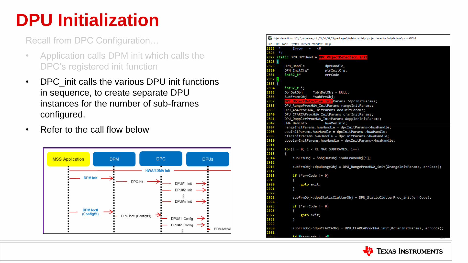
DPU Initialization Recall from DPC Configuration…
• Application calls DPM init which calls the
DPC’s registered init function
• DPC_init calls the various DPU init functions
in sequence, to create separate DPU
instances for the number of sub-frames
configured.
• Refer to the call flow below
23

DPU Configuration Recall from DPC Configuration…
• Application calls DPM_ioctl with different message types
• DPM_ioctl internally invokes the DPC’s registered ioctl function and passes the message to it
• DPC performs DPU configuration when handling the PRE_START_CFG command • The PRE_START_CFG handler calls wrapper functions
for each DPU, e.g. DPC_ObjDet_rangeConfig
• The wrapper allocates the resources required for the DPU and calls the corresponding DPU config function e.g. DPU_RangeProcHWA_config.
• Refer to the call flow below
24

DPIF: Datapath Interface
25
• Property
• numADCSamples
• RX interleaved/non-interleaved
• Complex/Real
• Buffer Pointer
Input ADC data
• Property
• Layout – RADAR CUBE RANGE DOPPLER RX TX (1)
• Buffer Pointer
Radar Cube
• Property
• Layout – DET MATRIX RANGE DOPPLER (1)
• Buffer Pointer
Detection Matrix
• Property
• Format – XYZV, RAEV
• Float
Point cloud
• Property
• snr
• noiseVal
Point Cloud SideInfo
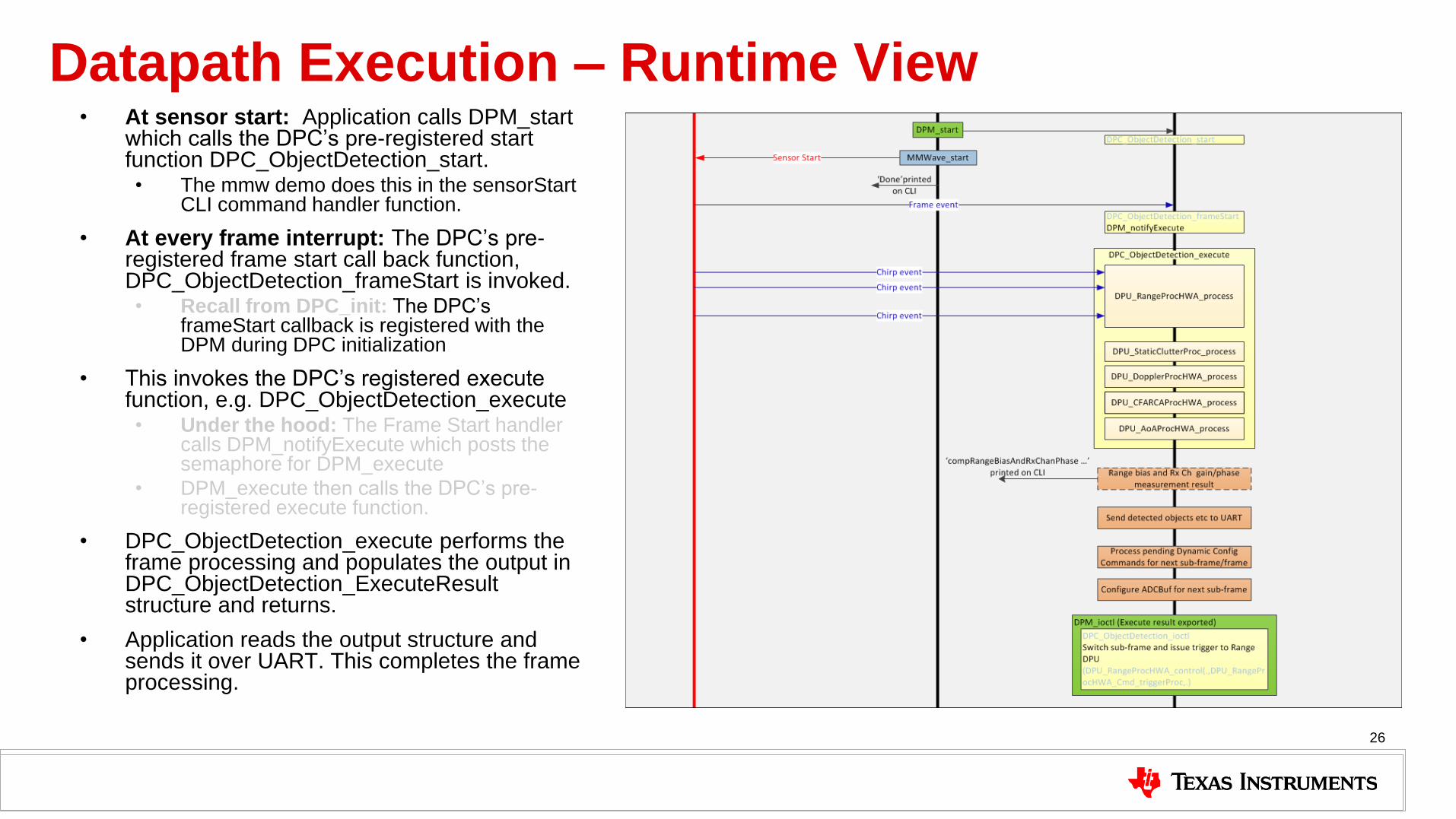
Datapath Execution – Runtime View • At sensor start: Application calls DPM_start
which calls the DPC’s pre-registered start function DPC_ObjectDetection_start. • The mmw demo does this in the sensorStart
CLI command handler function.
• At every frame interrupt: The DPC’s pre-registered frame start call back function, DPC_ObjectDetection_frameStart is invoked. • Recall from DPC_init: The DPC’s
frameStart callback is registered with the DPM during DPC initialization
• This invokes the DPC’s registered execute function, e.g. DPC_ObjectDetection_execute • Under the hood: The Frame Start handler
calls DPM_notifyExecute which posts the semaphore for DPM_execute
• DPM_execute then calls the DPC’s pre-registered execute function.
• DPC_ObjectDetection_execute performs the frame processing and populates the output in DPC_ObjectDetection_ExecuteResult structure and returns.
• Application reads the output structure and sends it over UART. This completes the frame processing.
26

Datapath Execution – Runtime View • At sensor start: Application calls DPM_start
which calls the DPC’s pre-registered start function DPC_ObjectDetection_start. • The mmw demo does this in the sensorStart
CLI command handler function.
• At every frame interrupt: The DPC’s pre-registered frame start call back function, DPC_ObjectDetection_frameStart is invoked. • Recall from DPC_init: The DPC’s
frameStart callback is registered with the DPM during DPC initialization
• This invokes the DPC’s registered execute function, e.g. DPC_ObjectDetection_execute • Under the hood: The Frame Start handler
calls DPM_notifyExecute which posts the semaphore for DPM_execute
• DPM_execute then calls the DPC’s pre-registered execute function.
• DPC_ObjectDetection_execute performs the frame processing and populates the output in DPC_ObjectDetection_ExecuteResult structure and returns.
• Application reads the output structure and sends it over UART. This completes the frame processing.
27

Datapath Execution – Runtime View • At sensor start: Application calls DPM_start
which calls the DPC’s pre-registered start function DPC_ObjectDetection_start. • The mmw demo does this in the sensorStart
CLI command handler function.
• At every frame interrupt: The DPC’s pre-registered frame start call back function, DPC_ObjectDetection_frameStart is invoked. • Recall from DPC_init: The DPC’s
frameStart callback is registered with the DPM during DPC initialization
• This invokes the DPC’s registered execute function, e.g. DPC_ObjectDetection_execute • Under the hood: The Frame Start handler
calls DPM_notifyExecute which posts the semaphore for DPM_execute
• DPM_execute then calls the DPC’s pre-registered execute function.
• DPC_ObjectDetection_execute performs the frame processing and populates the output in DPC_ObjectDetection_ExecuteResult structure and returns.
• Application reads the output structure and sends it over UART. This completes the frame processing.
28
Datapath Execution – Runtime View • At sensor start: Application calls DPM_start
which calls the DPC’s pre-registered start function DPC_ObjectDetection_start. • The mmw demo does this in the sensorStart
CLI command handler function.
• At every frame interrupt: The DPC’s pre-registered frame start call back function, DPC_ObjectDetection_frameStart is invoked. • Recall from DPC_init: The DPC’s
frameStart callback is registered with the DPM during DPC initialization
• This invokes the DPC’s registered execute function, e.g. DPC_ObjectDetection_execute • Under the hood: The Frame Start handler
calls DPM_notifyExecute which posts the semaphore for DPM_execute
• DPM_execute then calls the DPC’s pre-registered execute function.
• DPC_ObjectDetection_execute performs the frame processing and populates the output in DPC_ObjectDetection_ExecuteResult structure and returns.
• Application reads the output structure and sends it over UART. This completes the frame processing.
29

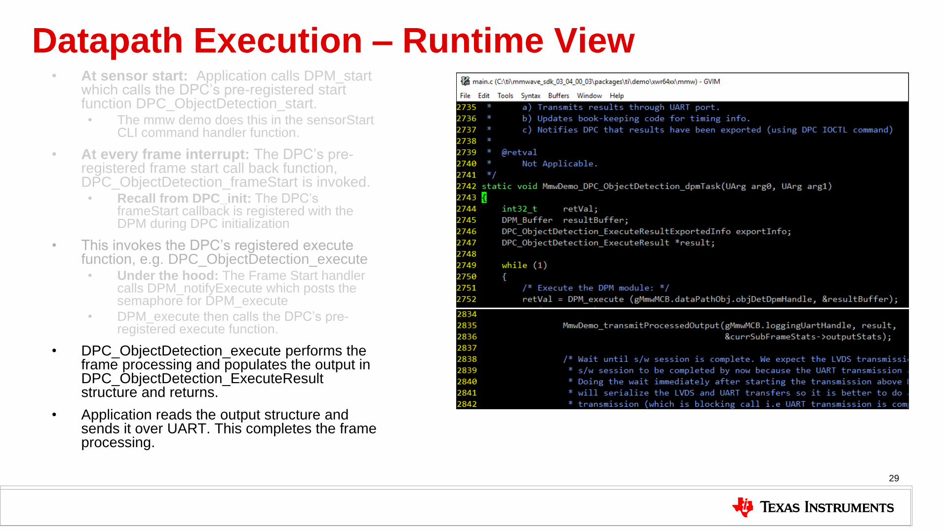
Datapath Execution – Runtime View • At sensor start: Application calls DPM_start
which calls the DPC’s pre-registered start function DPC_ObjectDetection_start. • The mmw demo does this in the sensorStart
CLI command handler function.
• At every frame interrupt: The DPC’s pre-registered frame start call back function, DPC_ObjectDetection_frameStart is invoked. • Recall from DPC_init: The DPC’s
frameStart callback is registered with the DPM during DPC initialization
• This invokes the DPC’s registered execute function, e.g. DPC_ObjectDetection_execute • Under the hood: The Frame Start handler
calls DPM_notifyExecute which posts the semaphore for DPM_execute
• DPM_execute then calls the DPC’s pre-registered execute function.
• DPC_ObjectDetection_execute performs the frame processing and populates the output in DPC_ObjectDetection_ExecuteResult structure and returns.
• Application reads the output structure and sends it over UART. This completes the frame processing.
30

DPUs and DPCs in SDK 3.x
31

RangeProc DPU
• Purpose: (1D FFT+ DC Range Calib) processing during active frame.
– Takes ADCBuf as input • interleaved or nonInterleaved
format • Single chirp or multichirp (DSP
mode only) • Either direct access (HWA mode
only) or via EDMA
– Produces RadarCube in L3 in user requested format (fixed set of formats described in data interface).
– Performs FFT using HWA or DSP based on configuration.
– Performs DC range calibration either inline (DSP mode) or at the end of all chirps (HWA mode).
• Supported architecture – R4F, C674x
– Different files for HWA based and S/W based implementation
32
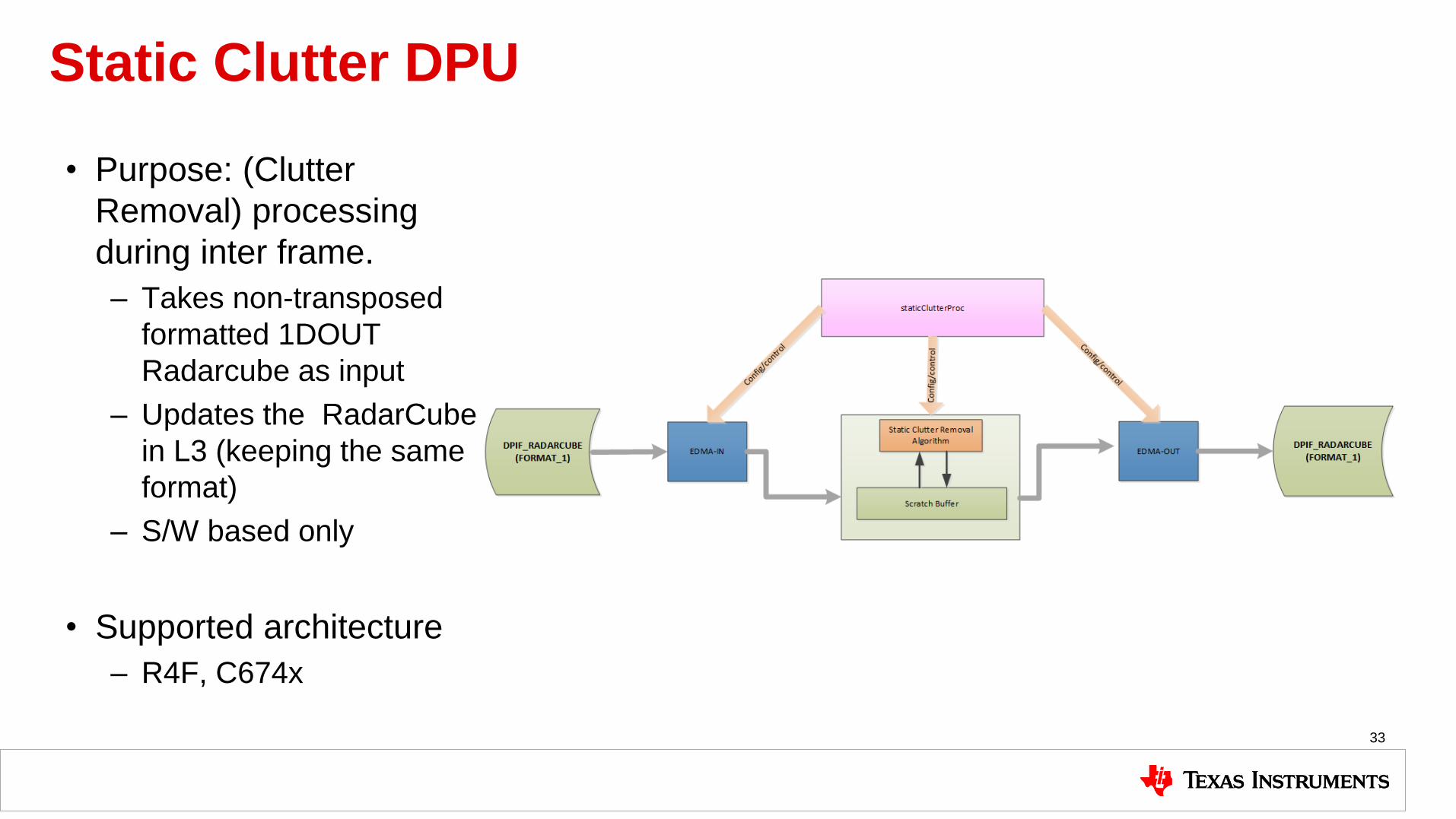
Static Clutter DPU
• Purpose: (Clutter
Removal) processing
during inter frame.
– Takes non-transposed
formatted 1DOUT
Radarcube as input
– Updates the RadarCube
in L3 (keeping the same
format)
– S/W based only
• Supported architecture
– R4F, C674x
33

Doppler DPU
• Purpose: (2D FFT + Energy Sum) processing during inter frame. – Takes non-transposed
formatted 1DOUT Radarcube as input
– Produces Detection Matrix in L3 in fixed format
– Performs FFT and Energy Sum using H/W(HWA) • S/W(DSP) based
implementation would be added in the SDK in future.
• Supported architecture – R4F, C674x
34

CFAR-CA DPU
• Purpose: (CFAR-CA +peak grouping) processing during inter frame.
– User can choose between various CFAR-CA implementation: CFAR-CA, CFAR-CASO, CFAR-CAGO
– Fixed Point implementation
– 2 pass implementation: first pass (optional) in Doppler direction and then second pass in Range direction
– Performs CFAR and PeakGrouping using H/W(HWA)
• S/W(DSP) based implementation would be added in SDK in future
– Takes Detection Matrix as input
– Produces bitmask of peaks and SNR information for AoA.
• Supported architecture – R4F, C674x
35
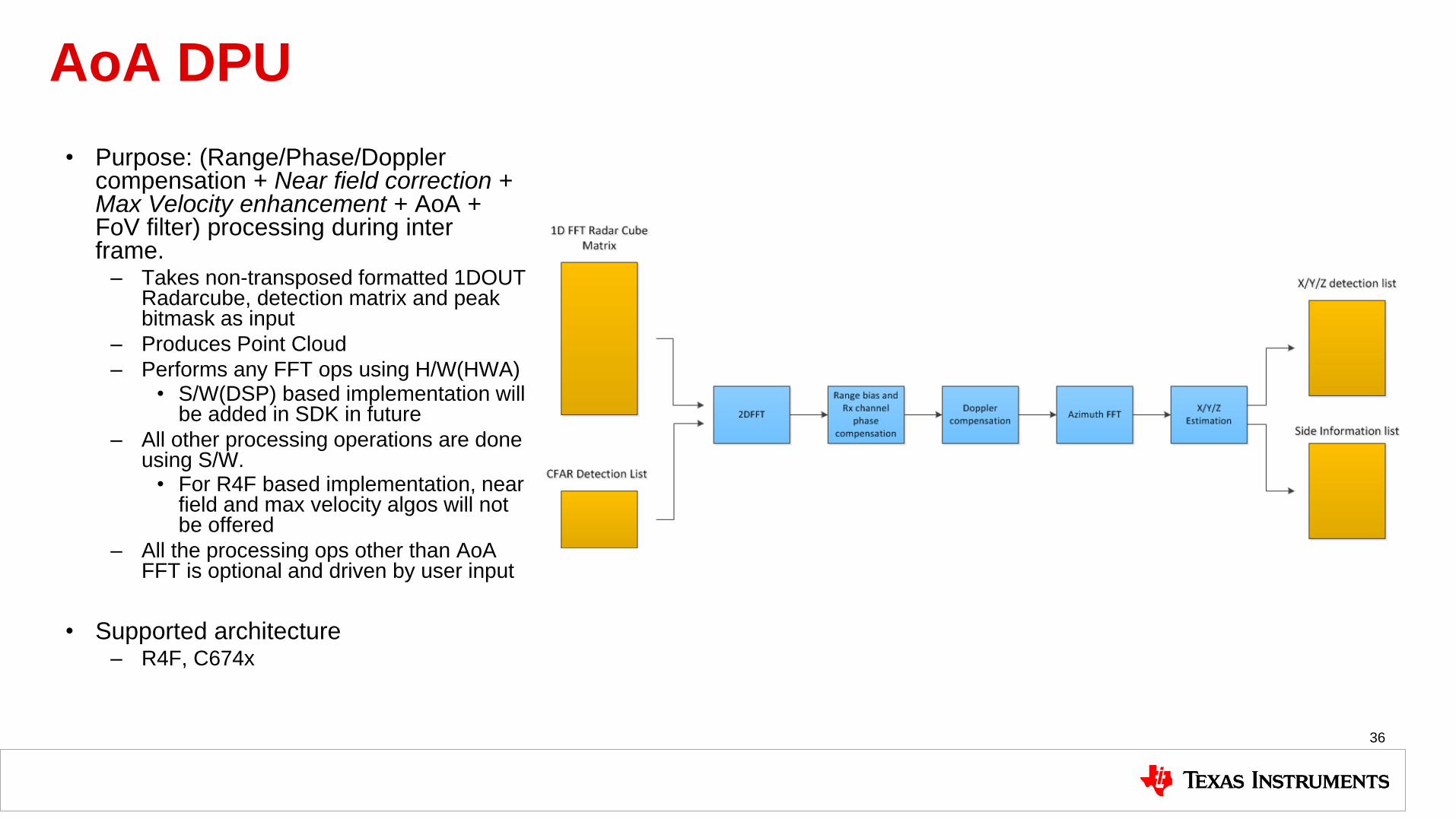
AoA DPU
• Purpose: (Range/Phase/Doppler compensation + Near field correction + Max Velocity enhancement + AoA + FoV filter) processing during inter frame.
– Takes non-transposed formatted 1DOUT Radarcube, detection matrix and peak bitmask as input
– Produces Point Cloud
– Performs any FFT ops using H/W(HWA) • S/W(DSP) based implementation will
be added in SDK in future
– All other processing operations are done using S/W.
• For R4F based implementation, near field and max velocity algos will not be offered
– All the processing ops other than AoA FFT is optional and driven by user input
• Supported architecture – R4F, C674x
36
R4F
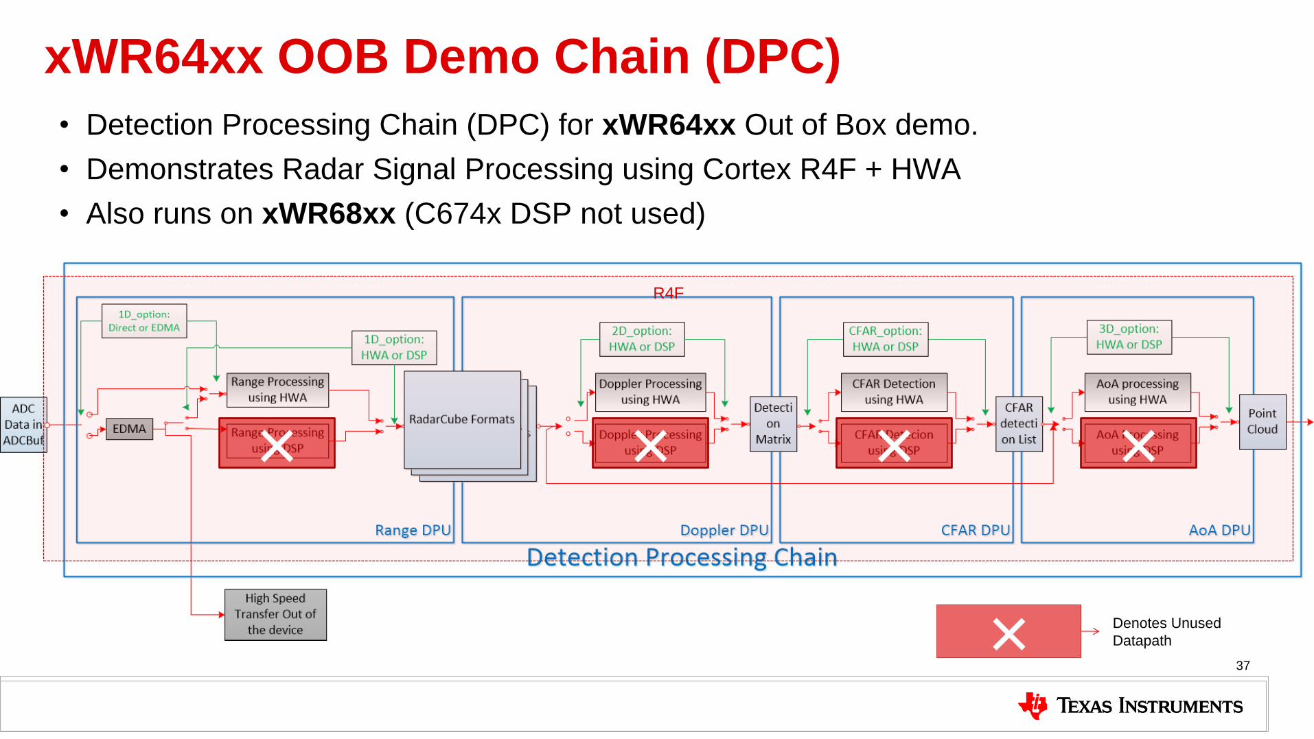
xWR64xx OOB Demo Chain (DPC)
• Detection Processing Chain (DPC) for xWR64xx Out of Box demo.
• Demonstrates Radar Signal Processing using Cortex R4F + HWA
• Also runs on xWR68xx (C674x DSP not used)
37
× × × ×
× Denotes Unused
Datapath

xWR68xx OOB Demo Chain (DPC) • Detection Processing Chain (DPC) for xWR68xx Out of Box demo.
• Demonstrates Radar Signal Processing using Cortex R4F + HWA + C674x DSP
• DSP provides higher performance and frees up R4F for other processing (e.g. Object Tracking)
38
R4F DSP
× × × ×
× Denotes Unused
Datapath

68xx OOB Demo - Application View
39
mmWave Device
mmWave application (MSS)
Object Detection DPC
RadarSS Firmware
mmWave
Front End
mmWave API DPM
Input/output over UART to external
TLV format
External Processor/Controlling entity
CLI mmWave Sensor Data
(point cloud)

Software Development and Debugging
40

Software Development Resources • Software Development Resources: The following resources are key to learning about software
development for TI processors.
• BIOS users guide: Installed as part of MMWAVE-SDK, it is available in the TI install directory e.g. C:\ti\bios_6_73_01_01\docs\Bios_User_Guide.pdf.
• This is the one of the best resources for learning about SYSBIOS and software development for TI processors.
• Linker command files: Understanding these is fundamental to developing applications for TI RTOS (SYSBIOS). Refer to the following resources:
• TI Linker Command File Primer
• Advanced Linker Techniques for Convenient and Efficient Memory Usage
• Other helpful resources
• Getting Started with Code Composer Studio v7
• Debugging Common Application Issues with TI-RTOS
• TI-RTOS Workshop
• Introduction to C6000 Architecture
• C6000 Cache - Overview (7 of 15)
• Using C6000 EDMA3 - Part 1 (13 of 15)
41

MMWAVE-SDK Debugging • Pre-requisites: The user should
be familiar with general CCS debugging techniques e.g. running code in CCS, putting breakpoints, observing the values of variables and memories etc. Following resources can be used to ramp-up on these topics if needed.
• Getting Started with Code Composer Studio v7
• Debugging Common Application Issues with TI-RTOS
• In addition to the above, the user must be familiar with basic procedures for running an MMWAVE application in CCS debug mode. This is explained in the mmWave Industrial Toolbox at the following page: • Using CCS Debug for
Development
42
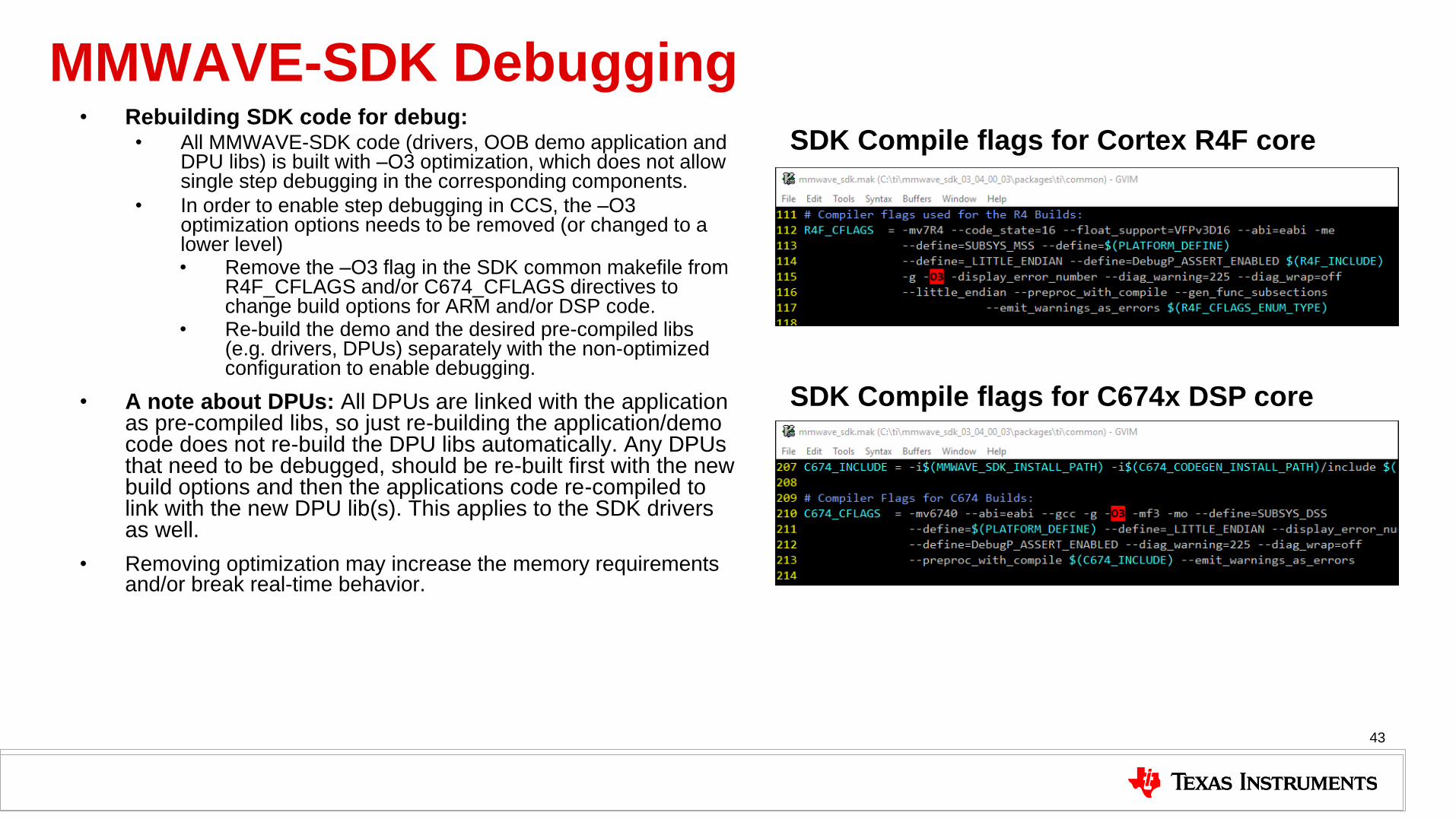
MMWAVE-SDK Debugging • Rebuilding SDK code for debug:
• All MMWAVE-SDK code (drivers, OOB demo application and DPU libs) is built with –O3 optimization, which does not allow single step debugging in the corresponding components.
• In order to enable step debugging in CCS, the –O3 optimization options needs to be removed (or changed to a lower level) • Remove the –O3 flag in the SDK common makefile from
R4F_CFLAGS and/or C674_CFLAGS directives to change build options for ARM and/or DSP code.
• Re-build the demo and the desired pre-compiled libs (e.g. drivers, DPUs) separately with the non-optimized configuration to enable debugging.
• A note about DPUs: All DPUs are linked with the application as pre-compiled libs, so just re-building the application/demo code does not re-build the DPU libs automatically. Any DPUs that need to be debugged, should be re-built first with the new build options and then the applications code re-compiled to link with the new DPU lib(s). This applies to the SDK drivers as well.
• Removing optimization may increase the memory requirements and/or break real-time behavior.
43
SDK Compile flags for Cortex R4F core
SDK Compile flags for C674x DSP core
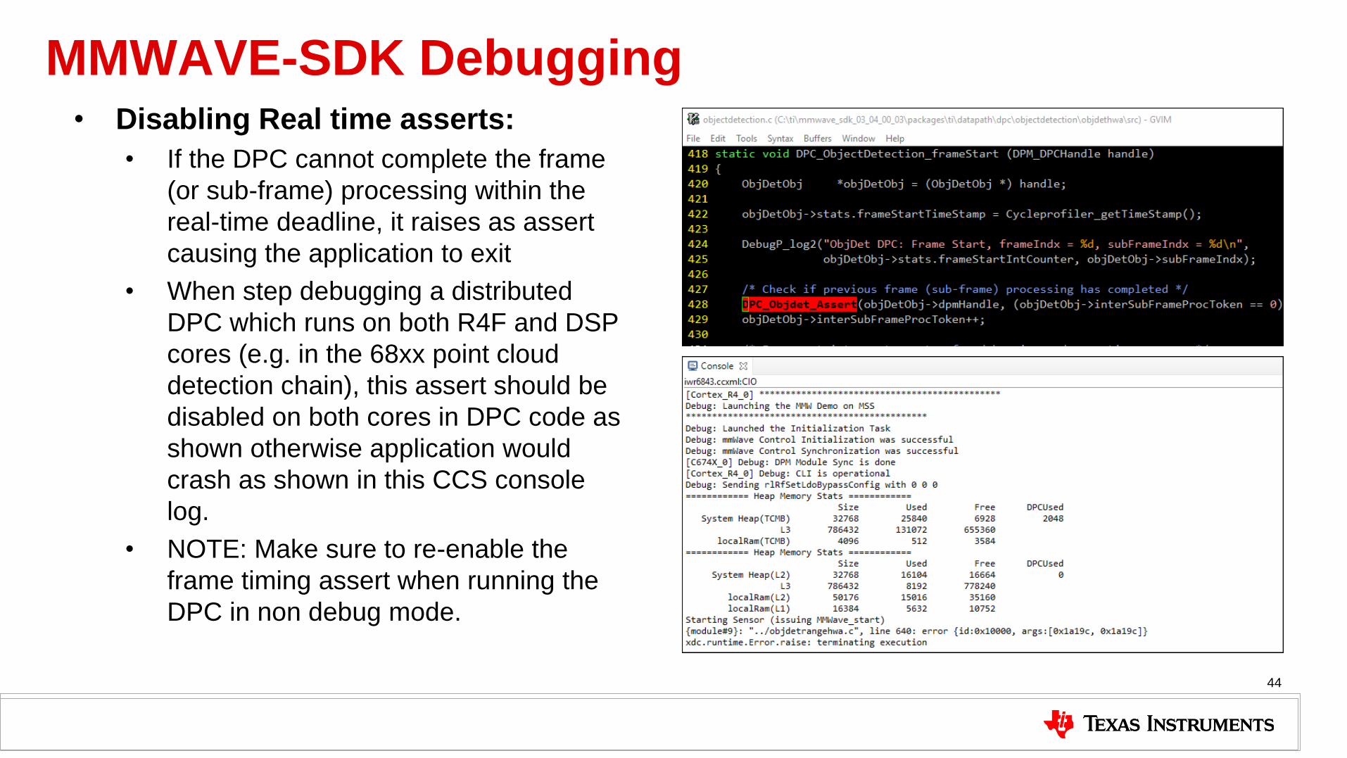
MMWAVE-SDK Debugging • Disabling Real time asserts:
• If the DPC cannot complete the frame
(or sub-frame) processing within the
real-time deadline, it raises as assert
causing the application to exit
• When step debugging a distributed
DPC which runs on both R4F and DSP
cores (e.g. in the 68xx point cloud
detection chain), this assert should be
disabled on both cores in DPC code as
shown otherwise application would
crash as shown in this CCS console
log.
• NOTE: Make sure to re-enable the
frame timing assert when running the
DPC in non debug mode.
44

Understanding Error Codes: Datapath Errors • When demo runs into error conditions, an
error code is generated and printed out on CCS console
• The error code is a negative integer e.g. shown in the picture.
• Can be from various sources such as Drivers, Control modules, DPC, DPU or demo (i.e. application)
• Error code defined as: (Module error code base minus Module specific error code) • The module error code base values are defined in
packages\ti\common\mmwave_error.h.
• The base error codes for DPC and DPU are define in packages\ti\datapath\dpif\dp_error.h
• Individual DPU specific error codes defined in the DPU header files
• Example: Parsing the error -30430 shown here
• The error code is from module with error base "-30000", which indicates it is DPU error
• Referring to dp_error.h, base "-30400" is from AOA Proc.
• Then find the error code in aoaprocdsp.h for error(-30) which is DPU_AOAPROCDSP_ESCRATCHSIZE
• NOTE: In SDK demos, these error codes are not sent out on UART so the demo must be run in CCS debug mode to get the error code
• Refer to SDK module documentation at the following location (in the SDK install directory) for more details: • file:///C:/ti/mmwave_sdk_03_05_00_04/packages/ti/demo/xwr68xx/mmw/docs
/doxygen/html/index.html#mmwave_error
45
Datapath Errors
-30000 = DPU Error base
-30430 = -30000 -400 -30
-400 = AOA Proc Error base
-30 = Insufficient Memory Error

Understanding Error Codes: mmWave Errors • Besides Datapath errors, there is another class
of errors known as mmWave module errors.
• These represent errors returned by the RF Front-End e.g. incorrect profile configuration.
• Defined as a combination of mmWave error, Susbsystem error and error level as shown. • mmwave errors defined
in packages\ti\control\mmwave\mmwave.h
• Subsystem errors defined in packages\ti\control\mmwavelink for mmwavelink.h
• Error level represents WARNING or ERROR.
• Example: The error shown in the log here indicates • The error is from module(-3100 i.e. mmwave) with
error -8 (MMWAVE_EPROFILECFG)
• The Subsystem (mmwavelink) error is 36 which is defined as RL_RET_CODE_PF_START_FREQ_INVAL_IN in mmwavelink.h, which indicates invalid start frequency specified in ProfileCfg API.
mmWave Link errors

Extending SDK architecture for advanced applications
47

Developing a Custom Radar Processing Chain Key considerations for developing a custom mmWave processing chain with SDK 3.x architecture
• Understand the data processing chain for the target application and model it in terms of DPC and DPUs
• Re-use the SDK Out of Box Detection Processing OR develop a new Detection Chain
– SDK Out of box DPC is a Range-Doppler based processing chain. – Lower angular resolution as compared to Range-Azimuth (Capon Beamforming) chain
• SDK Detection Chain re-used for Long Range People Detection and Area Scanner Demos • But a Higher resolution Capon Beamforming Detection Chain was developed for Indoor People Counting Demos
– Range Processing is still re-used irrespective of the rest of the Detection Processing
• Additional processing requirements beyond the OOB point cloud detection – Can the additional processing be added to an existing DPU or do we need to create a new DPU
• Object Tracking - new DPU • Static Object Detection - new DPU • 2D AoA (Angle of Arrival) using DSP – Enhancement to existing AoA DPU
• Enhancements needed at the DPC and Application level e.g.
– Tracking – Beam-steering – Static object detection
• Memory and MIPS requirements for the additional processing
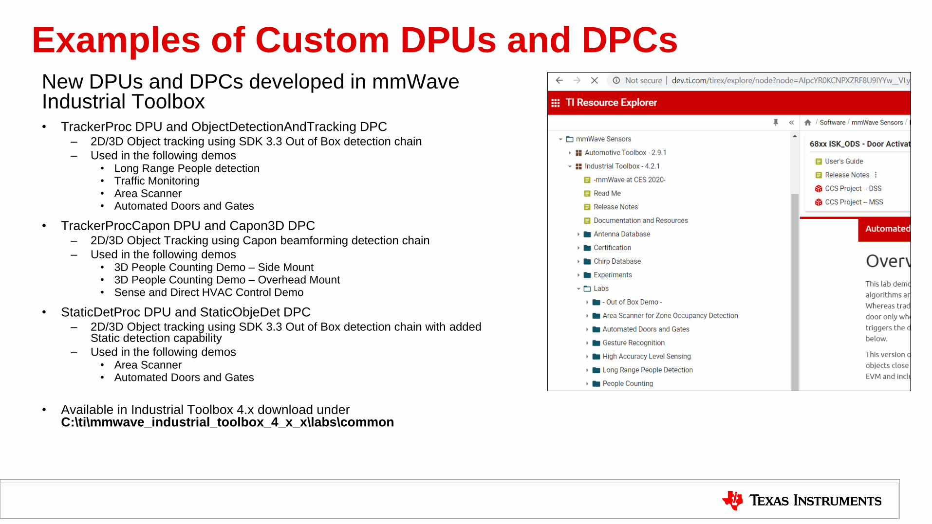
Examples of Custom DPUs and DPCs New DPUs and DPCs developed in mmWave Industrial Toolbox • TrackerProc DPU and ObjectDetectionAndTracking DPC
– 2D/3D Object tracking using SDK 3.3 Out of Box detection chain
– Used in the following demos • Long Range People detection • Traffic Monitoring • Area Scanner • Automated Doors and Gates
• TrackerProcCapon DPU and Capon3D DPC – 2D/3D Object Tracking using Capon beamforming detection chain
– Used in the following demos • 3D People Counting Demo – Side Mount • 3D People Counting Demo – Overhead Mount • Sense and Direct HVAC Control Demo
• StaticDetProc DPU and StaticObjeDet DPC – 2D/3D Object tracking using SDK 3.3 Out of Box detection chain with added
Static detection capability
– Used in the following demos • Area Scanner • Automated Doors and Gates
• Available in Industrial Toolbox 4.x download under C:\ti\mmwave_industrial_toolbox_4_x_x\labs\common
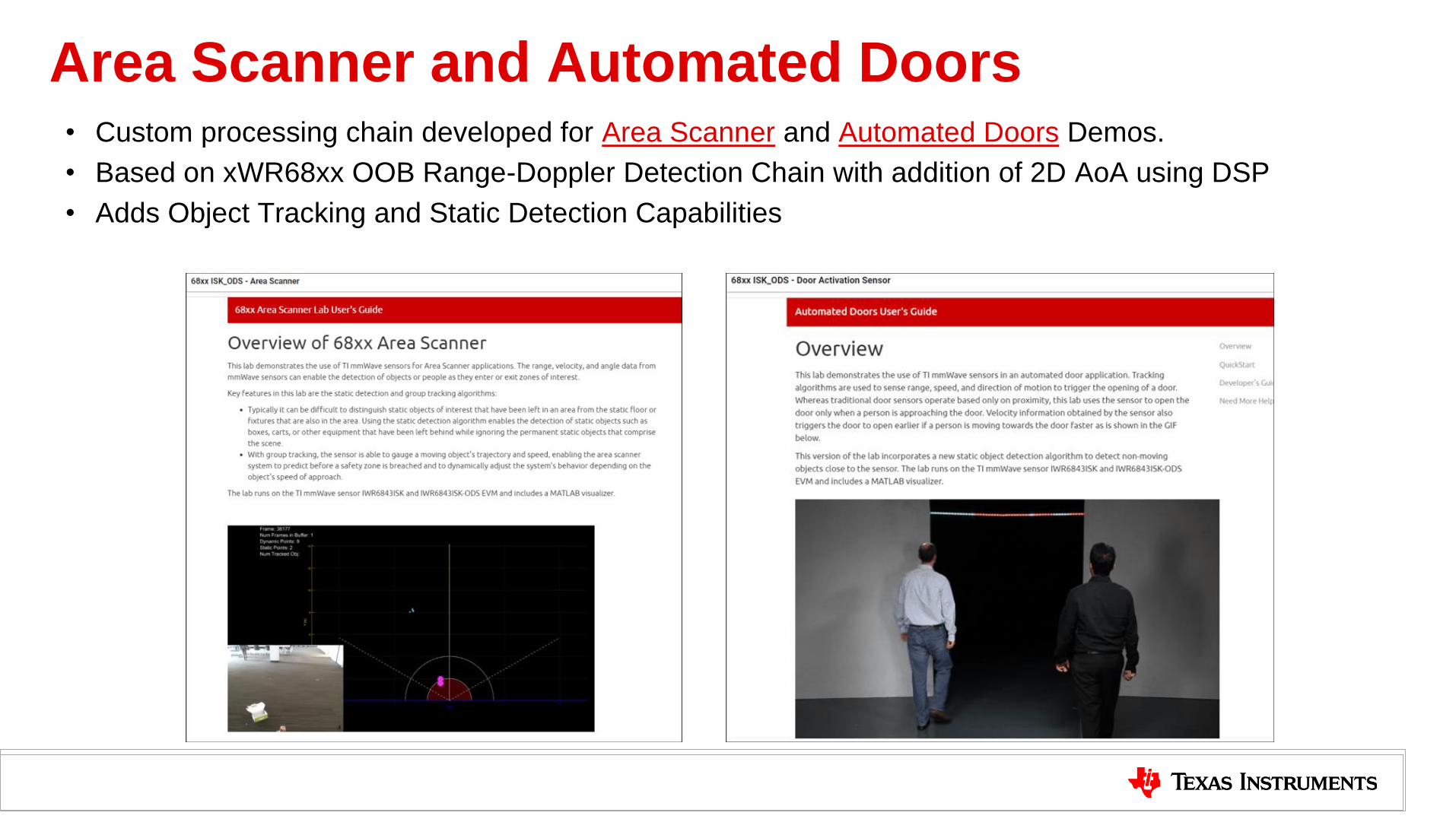
Area Scanner and Automated Doors • Custom processing chain developed for Area Scanner and Automated Doors Demos.
• Based on xWR68xx OOB Range-Doppler Detection Chain with addition of 2D AoA using DSP
• Adds Object Tracking and Static Detection Capabilities

Demo: Long Range Outdoor People Detection and Tracking
51

100m People Detection and Tracking
52
• Features
– SDK 3.3 Range Doppler Detection Chain with Object tracking on R4F
– Tracker DPU developed on top of SDK 3.x
– Runs on IWR6843ISK ES2.0 and IWR1843BOOST
– Supports 2D and 3D tracking
– People tracking tested upto 100m with IWR6843ISK ES2.0 (3TX SIMO)
– Re-used for Traffic Monitoring Demo on IWR1843/6843
– Supports ISK, ODS and AOP antennas (for Indoor applications such as Area
Scanner with Static Detection)
• DSP based AoA DPU modified to add 2D DoA for ODS/AOP
– Built on SDK 3.x OOB Demo
• Advanced features included for free e.g. Run time CFAR tuning, FoV
filtering, ADC data streaming over LVDS.
Sub frame based TX Beam Steering
Overview

3D Long Range Tracker Chain
53
DSP R4F
3D Tracker DPU
+ 2D DOA support
+ Spherical output
Tracking on R4F
Tracking on DSP
Point Cloud +
Tracker output
Uses SDK gTrack Lib
× × × ×
R4F
×
× Denotes Unused
Datapath
Denotes new or
modified components

SLYP721

IMPORTANT NOTICE AND DISCLAIMER
TI PROVIDES TECHNICAL AND RELIABILITY DATA (INCLUDING DATASHEETS), DESIGN RESOURCES (INCLUDING REFERENCE DESIGNS), APPLICATION OR OTHER DESIGN ADVICE, WEB TOOLS, SAFETY INFORMATION, AND OTHER RESOURCES “AS IS” AND WITH ALL FAULTS, AND DISCLAIMS ALL WARRANTIES, EXPRESS AND IMPLIED, INCLUDING WITHOUT LIMITATION ANY IMPLIED WARRANTIES OF MERCHANTABILITY, FITNESS FOR A PARTICULAR PURPOSE OR NON-INFRINGEMENT OF THIRD PARTY INTELLECTUAL PROPERTY RIGHTS.These resources are intended for skilled developers designing with TI products. You are solely responsible for (1) selecting the appropriate TI products for your application, (2) designing, validating and testing your application, and (3) ensuring your application meets applicable standards, and any other safety, security, or other requirements. These resources are subject to change without notice. TI grants you permission to use these resources only for development of an application that uses the TI products described in the resource. Other reproduction and display of these resources is prohibited. No license is granted to any other TI intellectual property right or to any third party intellectual property right. TI disclaims responsibility for, and you will fully indemnify TI and its representatives against, any claims, damages, costs, losses, and liabilities arising out of your use of these resources.TI’s products are provided subject to TI’s Terms of Sale (www.ti.com/legal/termsofsale.html) or other applicable terms available either on ti.com or provided in conjunction with such TI products. TI’s provision of these resources does not expand or otherwise alter TI’s applicable warranties or warranty disclaimers for TI products.
Mailing Address: Texas Instruments, Post Office Box 655303, Dallas, Texas 75265Copyright © 2020, Texas Instruments Incorporated