eastern indonesia national road improvement...
TRANSCRIPT
In Association with
Funded by the Australian Government
Eastern Indonesia National Road Improvement Project
Technical and Financial Audit Consultant
AUDIT REPORT
Project ESS-01
Sengkang-Impa Impa-Tarumpakae
Report No. B011
May 2011

Technical and Financial Audit Consultant (TFAC)
Doc. ID: B011 – ESS-01 Audit Report i
Foreword
This report describes the tasks performed by Pty Ltd undertaken through the EINRIP Technical and Financial Audit Consultant Project in support of the Australian Indonesia Partnership for Reconstruction and Development. Project implementation and management, as described in this report, is in accordance with the Scope of Services agreed in the contract between and the Australian Agency for International Development (AusAID). The Scope of Services was defined by the requests of the Client, time and budgetary constraints imposed by the client, and by availability of access to the Project site.
This report has been prepared on behalf of, and for exclusive use of, the Client as required for ongoing planning and implementation needs, and follows consultation between the Project team and the Agencies of the Government of Indonesia (GoI) involved in EINRIP. Reporting is in accordance with the requirements of the Head Contract for these services. The report is subject to, and issued in connection with, the provisions of the agreement between and the client.
accepts no responsibility whatsoever for, or in respect of, any use of or reliance upon this report by any third party.
The content of this report, and the recommendations made, may be used as required in accordance with Project needs.
Audit limitations
Not all matters defined by the Scope of Services could be addressed in the time available for field inspections. HIV prevention requirements of the contract were not examined.

Technical and Financial Audit Consultant (TFAC)
Doc. ID: B011 – ESS-01 Audit Report ii
Abbreviations and Acronyms
AIP Australian Indonesia Partnership for Reconstruction and Development
AF Audit Form
AusAID Australian Agency for International Development
CWC Civil Works Contractor
EINRIP Eastern Indonesia National Road Improvement Project
EMU EINRIP Monitoring Unit
GoI Government of Indonesia
GCC General Conditions of Contract
GS General Specification
PMSC Project Management Support Consultant
PMU Project Monitoring Unit
QAP Quality Assurance Plan (managed by RSC)
QCP Quality Control Plan (managed by CWC)
RSC Regional Supervision Consultant
TFAC Technical and Financial Audit Consultant
TOR Terms of Reference (EINRIP-TFAC)

Technical and Financial Audit Consultant (TFAC)
Doc. ID: B011 – ESS-01 Audit Report iii
Report Register
Report No. Name of Report
A001 Inception Report
A002 General Audit Plan
B001 Final Audit Report – Package EBL-01, Tohpati – Kusamba
B002 Final Audit Report – Package ENB-01AB, Sumbawa Besar Bypass
B003 Final Audit Report – Package EKB-01, Pontianak - Tayan
B004 Final Audit Report – Package ESR-01, Tinanggea – Kasipute
B005 Final Audit Report – Package ESS-02, Bantaeng - Bulukumba
B006 Final audit Report – Package EBL- 02, Tohpati –Kusamba, Stage 2
B007 Final Audit Report – Package ENB-01C, Pal IV – KM 70, Sumbawa
B008 Final Audit Report – Package ENB-02, KM 70 – Cabdin Dompu, Sumbawa
B009 Final Audit Report – Package ENB-03, Cabdin Dompu - Banggo, Sumbawa
B010 Final Audit Report – Package ESR-02, Bambaea – Sp. Kasipute
B011 Final Audit Report – Package ESS-01, Sengkang-Impa Impa-Tarumpakae

Technical and Financial Audit Consultant (TFAC)
Doc. ID: B011 – ESS-01 Audit Report iv
TABLE OF CONTENTS
SECTION A AUDIT FINDINGS .................................................................................. 1
A1 INTRODUCTION ................................................................................................. 1
A2 AUDIT FINDINGS ................................................................................................ 2
Audit Finding 1: Insufficient Traffic Management ................................................ 2
Audit Finding 2: Quality Control Plan and Method Statements Not Fully Utilised ............................................................................................... 3
Audit Finding 3: RSC Quality Assurance Plan on site not current ....................... 4
Audit Finding 4: Holding points ........................................................................... 5
Audit Finding 5: Survey and Level Control .......................................................... 6
Audit Finding 6: Work Scheduling ....................................................................... 7
Audit Finding 7: Vehicle Overloading .................................................................. 8
Audit Finding 8: Environmental ........................................................................... 9
Audit Finding 9: Road Width Too Narrow .......................................................... 10
Audit Finding 10: Pipe Drain Construction ........................................................ 11
Audit Finding 11: U-Ditch Not Correct ............................................................... 12
Audit Finding 12: Retaining Wall Filter Layer Not Installed ................................ 13
Audit Finding 13: U-Ditch Construction Quality ................................................. 14
Audit Finding 14: U-Ditch Covers on Curves..................................................... 15
Audit Finding 15: Cross Drain at Station 5+375 ................................................ 16
Audit Finding 16: Grade preparation Shape and Compaction ........................... 17
Audit Finding 17: Earthworks and Pavement Compaction for Widening ............ 18
Audit Finding 18: Aggregate Base A Levelling and Compaction ....................... 19
Audit Finding 19: Prime Coat ............................................................................ 20
Audit Finding 20: Power Broom ........................................................................ 21
Audit Finding 21: Incomplete Asphalt Binder and Asphalt Base Job Mixes ....... 22
Audit Finding 22: Asphalt Finisher Screed Vibration ......................................... 23
Audit Finding 23: Preparatory Work before Asphalt Construction ..................... 24
Audit Finding 24: Asphalt Binder Course Cross-Falls Incorrect ......................... 25
Audit Finding 25: Storage for Batu Bara (coal) ................................................... 25
Audit Finding 26: Asphalt Binder AC BC Independent Test Results .................. 26
Audit Finding 27: Asphalt Binder AC BC Independent Testing .......................... 26
Audit Finding 28: Selected embankment quantities for sub-grade improvement .................................................................................... 27
SECTION B TECHNICAL REPORT ........................................................................ 28
B1 INTRODUCTION ............................................................................................... 28
B1.1 EINRIP Projects ............................................................................... 28
B1.2 Project Objectives ............................................................................ 28
B1.3 Requirements of the Audit ................................................................ 28
B1.4 Audit Objectives for Package ESS-01 .............................................. 29
B1.5 General Comments on Package ESS-01 ......................................... 30
B2 PROJECT SUMMARY ....................................................................................... 33

Technical and Financial Audit Consultant (TFAC)
Doc. ID: B011 – ESS-01 Audit Report v
B2.1 Contract Scope of Works ................................................................. 33
B2.2 Regional Supervision Consultant (RSC) ........................................... 33
B2.3 Construction Works Contractor (CWC) ............................................. 33
B2.4 Audit Technical Administrative ......................................................... 33
B2.4.1 RSC Quality Assurance Plan ................................................................ 33 B2.4.2 RSC Check Lists .................................................................................. 33 B2.4.3 CWC Quality Control Plan .................................................................... 33 B2.4.4 CWC Method Statements ..................................................................... 33
B2.5 Implementation................................................................................. 33
B2.5.1 Materials Sources ................................................................................ 33 B2.5.2 Materials Production ............................................................................ 34 B2.5.3 Setting out of Works ............................................................................. 36 B2.5.4 Drainage .............................................................................................. 37 B2.5.5 Construction......................................................................................... 47 B2.5.6 Surface Preparation ............................................................................. 55 B2.5.7 Prime Coat ........................................................................................... 55 B2.5.8 Tack Coat ............................................................................................ 55 B2.5.9 Asphaltic Concrete Construction .......................................................... 56
B2.6 BRIDGES AND MAJOR STRUCTURES .......................................... 57
B2.7 CONSTRUCTION EQUIPMENT ...................................................... 57
B2.7.1 Equipment Still Required ...................................................................... 57 B2.7.2 Existing Equipment Requiring Maintenance or Replacement ................ 57
B2.8 TRAFFIC CONTROL........................................................................ 57
B2.9 TRAFFIC SIGNS .............................................................................. 58
B2.10 SPEED RESTRICTIONS ................................................................. 59
B2.11 VEHICLE OVERLOADING ............................................................... 59
B2.12 ROAD MAINTENANCE .................................................................... 60
B2.13 SAFETY ISSUES ............................................................................. 61
B2.14 ENVIRONMENTAL ISSUES ............................................................ 61
B2.15 DESIGN REVIEW ............................................................................ 62
B2.15.1 Extended Lined Ditches ....................................................................... 62 B2.15.2 Culvert Relocation ................................................................................ 64
B2.16 TFAC Construction and Materials Testing ........................................ 64
SECTION C FINANCIAL AUDIT.............................................................................. 65
ANNEXURES ............................................................................................................. 1
ANNEX-1 MATERIALS LABORATORY TEST RESULTS ............................................... 1
ANNEX-2 AUDIT FORMS ............................................................................................... 1
ANNEX-3 ATTENDANCE REGISTER............................................................................. 1
ANNEX-4 LETTER NO. TFAC 2011/006 „REQUIRED ENGINEERS ACTION ON WORKS QUALITY DEFICIENCIES‟ .................................................................... 1
ANNEX-5 CORRECTIVE ACTION PRIORITIES ............................................................. 1

Section A –Audit Findings
Doc. ID: B011 – ESS-01 Audit Report
SECTION A – AUDIT FINDINGS
Eastern Indonesia National Road Improvement Project (EINRIP)

Section A –Audit Findings
Doc. ID: B011 – ESS-01 Audit Report 1
SECTION A AUDIT FINDINGS
A1 INTRODUCTION
The Audit of Package ESS 01, Sengkang-Impa Impa-Tarumpakae Batas, South East Sulawesi, was conducted on site from 19th April to 24th April 2011. The Closing Meeting was conducted in Makassar on 25th April 20011.
a) Audit Findings
The report describes the findings of the Audit. The findings are supported by TFAC
technical and financial reports, TFAC independent field and laboratory test data and by a Closing Meeting process through which auditees were given the opportunity to debate the findings.
Findings presented at the Closing Meeting and auditee responses are contained in Audit Forms provided in Annex-2.
b) Report Distribution
It is recommended that this report is shared with the EINRIP Project Manager, EINRIP PMU, PMSC, RSC and the Civil Works Contractor.
Many of the permanent works so far completed fail to comply with specified
requirements in ways that are likely to significantly compromise future
performance. The Engineers Quality Assurance procedures have been entirely
ineffective. Letter No. TFAC 2011/006 provided in Annex- 4 refers to this issue.
Further comment is unnecessary.

Section A –Audit Findings
Doc. ID: B011 – ESS-01 Audit Report 2
A2 AUDIT FINDINGS
An additional section has been added “Corrective Action priority” to address a concern raised at the Closing Meeting. The classification system used is described by Annex 5
Audit Finding 1: Insufficient Traffic Management
Audit Finding There was insufficient traffic control and traffic management on the project site
Finding Support There were many work locations on site that encroached onto the carriageway. At several of these sites there were no traffic signs, traffic barriers, markers or police lines. This situation was noted at some locations where existing culverts was being extended and at locations where the excavation for road widening had not yet been backfilled. It was also noted that there were no traffic signs or traffic control at locations where equipment and/or works force was working on the project road.
Contract Document Reference
General Specification 1.8.1.1 Description (a) The Contractor shall provide traffic control devices and services for the control and protection of Contractor’s and Engineer’s employees, and road users through areas of construction, including locations of sources of materials and haul routes---- (b) The Contractor shall furnish, install and maintain at all times during the Time for Completion, necessary traffic signs, barricades, flexible and rigid guardrails, lights, signal, road marking ------
Impact Potential for traffic accidents and reduction in public and works force safety
Suggestion The Engineer must enforce the requirements of the contract documents with respect to traffic, works force and public safety.
Should the situation not improve adequately then the Engineer has the power to suspend the works pending better traffic control and sign posting.
If the work is not done then payment for traffic management should be withheld (Pay Item 1.8)
Corrective Action Priority
WA and MA – immediate corrective action required

Section A –Audit Findings
Doc. ID: B011 – ESS-01 Audit Report 3
Audit Finding 2: Quality Control Plan and Method Statements Not Fully Utilised
Audit Finding The Contractor has prepared a Quality Control Plan and Method Statements for most site activities but these are not being fully utilised on the construction site.
Finding Support Many aspects of the work being implemented do not conform to the design or specification requirements. Examples where this is evident are:
Cross falls incorrect on Aggregate Base A and AC-BC layer. A check carried out on site by the Auditor showed one section of Base A to be 120mm low at the road centreline. Checks carried out by the Auditor on completed asphalt binder showed cross-falls to vary between 1% and 4.2% (the design cross-fall is 3%)
U-ditch top levels and alignment did not conform to the design requirements. The top levels of several sections of completed U-ditches are very uneven and do not follow the vertical alignment of the pavement
RCP jointing and installation does not conform to the design requirements in several respects .
Low concrete strengths were recorded by the Auditor on large proportion of the completed concrete structures. On concrete lined ditches the strengths recorded were as low as 110.7kg/cm
2
The requirements of Holding Points are not being applied. This is evident by the numbers of non-conformities for work that has progressed past a holding point and noted by the Auditor
Contract Document Reference
General Specification 1.21.2.1 QC Plan General Requirements;
General Specification 1.21.4 Holding Points
Impact Sub-standard work and non-conforming components of the project
Reduced service life of the facility
Increase in road and drainage maintenance requirements and costs
Suggestion The Engineer must review the Contractor‟s Quality Control Plan and method statements, approve these if adequate, and ensure the Contractor adheres to the requirements of the approved Quality Control Plan
Corrective Action Priority
WA and MA - immediate corrective action required

Section A –Audit Findings
Doc. ID: B011 – ESS-01 Audit Report 4
Audit Finding 3: RSC Quality Assurance Plan on site not current
Audit Finding The RSC does not have an effective up-to-date copy of their Quality Assurance Plan on site.
Finding Support An up-to-date hard copy of the RSC‟s Quality Assurance Plan is not available on site. The version the RSC has on site is the 2010 workshop copy which is mainly power point presentations (there is a soft copy of the 2009 version in English on the RSC site computer). RSC Check Lists are available on site but these are not being fully implemented. The requirements of Holding Points are not applied
A few of the checklists on the Requests For Works from the Contractor have been implemented, but most of these forms remained blank.
Non-conformities have been identified at most places where holding points should have been applied i.e : cross fall of Aggregate Base A and AC-BC layer, backfilling & filter layer behind the retaining wall, U-ditch alignment and top level, RCP jointing, low concrete strength, traffic signs and traffic management, etc.
Contract Document Reference
General Specification 1.21.3 Quality Assurance Plan:- The Engineer will prepare and implement a Quality Assurance Plan, based in part on the effectiveness and reliability of the Contractor’s Quality Control Plan.
Impact Large number of non-conformities
Sub-standard work
Reduced facility service life
Increased maintenance requirement for the completed facility and increased maintenance costs
Suggestion The Engineer must ensure the RSC site staff are supplied with an up-to-date copy of their Quality assurance plan in the Indonesian language
The Engineer must ensure that the requirements of this plan are fully implemented on site.
RSC Field Staff must implement and develop the checklists in accordance with his assignment and resposibilities. Holding points should be supervised and checked properly.
Approval of the Requests For Work should be supported by proper implementation and completion of check lists.
Corrective Action Priority
WA and MA - immediate corrective action required

Section A –Audit Findings
Doc. ID: B011 – ESS-01 Audit Report 5
Audit Finding 4: Holding points
Audit Finding The requirement of the Holding Points are not being recognised by either the RSC or the Contractor
Finding Support The lack of survey control, inadequate compaction of sub-grade, incorrect road cross falls, pipe culverts, drainage structures, etc. reinforce the Auditor‟s view that holding points are not being recognised
Contract Document Reference
General Specification 1.21.4 Holding Points
General Specification 1.21.7.1 Contractor‟s Internal NCR;- Should the Contractor’s QC reporting indicate that the Work is not in conformance, the QC Manager shall issue in internal Non-Conformance Report (NCR) to the Contractor, with a Copy to the Engineer, including a response time.
Impact Large number of non-conformities
Sub-standard work
Reduced facility service life
Suggestion The requirements of Holding Point must be enforced. Holding Points are the basic tools for controlling the quality of the works.
Notwithstanding the requirements of General Specification 1.21.4 Holding Points “The contractor shall not be bound to delay work if the Engineer’s or Engineer’s Assistant is not present at the agreed time, provided notice has been correctly given, and provided all other applicable requirements have been met”.
NO payment should be made for work that proceeds beyond a Holding Point and is sub-standard and any form. This latter condition must be applied and enforced by the Engineer, FIDIC 3.2 General Conditions (a) any failure to disapprove any work, Plant or Materials shall not constitute approval, and shall therefore not prejudice the right of the Engineer to reject the work, Plant or Materials;
Corrective Action Priority
WA and MA immediate corrective action required

Section A –Audit Findings
Doc. ID: B011 – ESS-01 Audit Report 6
Audit Finding 5: Survey and Level Control
Audit Finding The Auditor found the survey and level control on the project to be completely inadequate.
Finding Support There are not enough survey control points located on the project to adequately control the horizontal and vertical alignment of the road or the levels on the structures. Over the first 8+000 km there are virtually no survey reference points (i) At station 2+700 to 2+900 on one side of the road lined drain final top levels is 200 to 300mm higher than the other side. (ii) On the left side of the road the retaining wall is lower than the top of the lined drain. These items are not in accordance with the design requirements. (iii) The same situation occurs at station 4+000. (iv) Several sections of the pavement that already had AC laid have the wrong cross falls and some curves have the incorrect super elevation runoff constructed into the road.(v) Retaining walls are misaligned in a few locations. (vi) Incorrect road cross falls and shape
Contract Document Reference
Design Drawings
General Specification 1.9.4.2 The Contractor shall accurately survey and install additional permanent bench marks at certain locations along the project to enable redesign, pavement level surveys or setting out of the work to be done. Permanent bench marks shall be established on ground which is not subject to movement.
General Specification 1.9.4.3 The Contractor shall set construction stakes, profile, pegs and other references as necessary to establish lines and grades for new construction, pavement edge correction, shoulder widths,--
Impact Project not constructed according to the design requirements
Loss of facility
Poor visual impact
Possible drainage malfunction during service
Suggestion Contractor to install and RSC to check that a complete and adequate survey control together with regular offset level check points is established before any further drainage is installed or construction proceeds past sub-grade preparation
Contractor to ensure their surveyor is fully conversant with the survey requirements for the project
No works to proceed past a holding point until RSC certifies the survey work is correct
All work should be suspended until this issue is corrected
Corrective Action Priority
WA and MA - immediate corrective action required -

Section A –Audit Findings
Doc. ID: B011 – ESS-01 Audit Report 7
Audit Finding 6: Work Scheduling
Audit Finding The scheduling of some work components of the Contractors operations need to be more carefully assessed and applied. Some components of work are not programmed to best advantage.
Finding Support Due to advanced works long sections of sub-grade preparation and side ditch excavation are at risk damage and they present traffic hazards. The contractor has opened up a lot of excavation for lined drains well ahead of construction. The same applies to the pavement widening which needs to be followed up with the base as soon as possible after the sub-grade has been approved. There is now a risk of damage occurring due to rain and the extensive open edges of the existing road present a traffic hazard. There are several locations where these activities are ongoing.
Contract Document Reference
Drawings
Drawings Notes: Sequence of Work
General Specification 2.1.1.6 Work Scheduling; General Specification 1.8.2.1 Work Sequence and Traffic Management Plan
Impact Traffic and public safety hazard
Environmental issue due to the volumes of loose spoil left at the sides of excavations
Suggestion The Contractor should attempt to complete opened up works as soon as possible and program future works to follow with the next stage of the work as soon as possible. In particular he needs to accelerate the completion of the following activities before opening up more areas of work:
complete drainage including discharge paths to the point where it is functional
backfill and filter material for retaining walls
backfill and granular layers in widening trenches sta 0 to 4 +
Construction of base A in pavement widening excavations
repositioning of power poles
casting of curbs
placing of subsoil drains
placing of curbs km 0 – 4
completion of pipe drains
Then and only then do wearing course
footpath concrete blocks
A detailed Critical Path analysis (fully based on the Contractors resources) should be prepared for this project and reviewed and approved by the Engineer in accordance with General Specification 1.12. Construction Schedules
Corrective Action Priority
WA and MA - immediate corrective action required

Section A –Audit Findings
Doc. ID: B011 – ESS-01 Audit Report 8
Audit Finding 7: Vehicle Overloading
Audit Finding The Contractor is using and fully loading, trucks with body capacities that produce axle loads much higher than allowable.
Finding Support The Contractor is presently operating haulage trucks of two different configurations. One of these is a 2 axle truck with a body that carries 7-8 cubic metres. The other is a 3 axle truck with a body that carries15-16 cubic metres and can be loaded to 20 cubic metres. The 2 axle truck fully loaded all up weight will be about 23 tonnes giving 16 tonnes on the rear axle. The 3 axle truck fully loaded all up weight will be about 35 tonnes or 25 tonnes on the rear axle group. A legal load for the 2 axle truck is 10 tonnes on the rear axle and for the 3 axle truck 20 tonnes on the rear tandem axle. Both units are grossly overloaded.
Contract Document Reference
Drawing Notes Page 2: Truck Loading- Trucks engaged in the works shall be legally loaded trucks.
General Specification 1.5.3.3 Transportation Weight Limitations and Damage. The Engineer may impose weight restrictions for the protection of any existing road or structure within the vicinity of the project. The Contractor shall be responsible for any damage to roads or structures resulting from his construction operations
Impact Severely stressed roads over which the loaded trucks travel
Accelerated pavement damage
Increased road maintenance costs
Premature road improvement costs
Suggestion Contract Document conditions must be enforced by the Engineer
All truck loads to be limited to 10 tonnes per rear axle and 6 tones per front axle
Corrective Action Priority
MA - immediate corrective action required

Section A –Audit Findings
Doc. ID: B011 – ESS-01 Audit Report 9
Audit Finding 8: Environmental
Audit Finding The Contractors operations are causing environmental damage
Finding Support The Contractor is depositing excavation waste materials over the sides of the road into gullies and onto private property. This is creating pollution and effecting private land and waterways
Contract Document Reference
General Specification 1.17.1.1 Description (b) The Contractor shall take all reasonable steps to protect the environment (both on and off the Site , including base camp and other installations under the control of the Contractor) and to limit damage and disturbance to people and property resulting from pollution, noise and other results of his operations
General Specification 1.17.2 Environmental Management
Impact Potential cost to Local Authority to clean up after project finished if not agreed with land owners
Loss of productive land
Siltation of waterways
Suggestion Unless otherwise agreed in writing by the land owners and/or the local authority then the Contractor must clean up this material as soon as possible.
RSC Environmental Specialist and SSE must assess the overall situation and report to the Engineer with recommendations.
Corrective Action Priority
WA and MA - immediate corrective action required

Section A –Audit Findings
Doc. ID: B011 – ESS-01 Audit Report 10
Audit Finding 9: Road Width Too Narrow
Audit Finding Road width (from inner side to inner side of U-ditch walls) was found to be less than as required by the Drawings
Finding Support At Station 2+300 and adjacent locations, the width between the lined ditches on each side of the road was measured and found to be only 8,20-8,40m (this is less than 8,50m defined in the Drawings).
Contract Document Reference
Drawings
Impact Curb Type L1 will not be matched with the limited space now available;
The foot path will be closer to the traffic lane
The usable road width will be less than designed
Suggestion This is now a difficult situation to correct as the lined ditches have been completed for each side of the road at the offending locations.
The impact on the functioning of the completed carriageway will be nominal but it is essential that the RSC checks and identifies non-compliant road widths before work progresses too far.
The Contractor and the Engineer should ensure that all future works are properly set out so this situation is not repeated.
The Engineer should apply a small payment reduction for the
reduced quantity of pavement material.
Corrective Action Priority
WC – corrective action required but some delay is acceptable

Section A –Audit Findings
Doc. ID: B011 – ESS-01 Audit Report 11
Audit Finding 10: Pipe Drain Construction
Audit Finding The construction of the pipe drain designed for sections of the road commencing from station 0+000 was found by the Auditor to be very poor.
Finding Support The contractor is currently installing pipe drains from station 3+000 forward. Both the vertical and horizontal alignment of these pipes is irregular and very uneven The pipes have not been laid on an even bed as they were being installed as could be seen by the irregular vertical and horizontal alignment of the pipes on site.
The jointing of the pipes is very poor and water will leak into the soil
The haunching of the pipes is very poor and ineffectual
The pipes have not been bedded up the bottom third of the pipe as required by standard practice and indications are that the pipes have just been laid on the ground that was excavated by the machine without any form of levelling or compaction of the base on which the pipes were to be laid.
The manufacture of the pipes is poor in that the male flange is too large to fit into the socket of the adjoining pipe
Contract Document Reference
Drawings
Bills of Quantity
Impact Water will leak out of the pipes and soften the sub-grade
The misaligned and un-compacted bed on which the pipes have been laid will consolidate over time and the footpath constructed over the pipes will settle
The misalignment of the pipes and the gaps at the pipe joints will allow rubbish to be trapped in the joints with eventual reduction in pipe capacity and probable pipe blockages
Maintenance cost swill be incurred to re-instate the footpaths
If pipes have to be re-laid at a later stage then the cost of the relaying will fall on the local authority
Suggestion All improperly bedded and/or aligned pipes should be removed and re-laid correctly
All pipe manufacture must to be checked and the moulds modified to ensure the flanges can fit together properly
No payment should be made for these pipes until correctly aligned and correctly backfilled
The Engineer should issue a formal Rejection Notice
Corrective Action Priority
WA and MA - immediate corrective action required – Formal rejection notice required

Section A –Audit Findings
Doc. ID: B011 – ESS-01 Audit Report 12
Audit Finding 11: U-Ditch Not Correct
Audit Finding A constructed U-ditch does not conform to the drawing requirements
Finding Support The levels of the covered U-Ditch level at Station 2+900 and the adjacent U-ditch do not conform to the requirements of the Drawings
The top level of the constructed U-ditch at one side of the road is higher than the other side, and it is also higher than the adjacent Retaining Wall.
This problem is common for road side works from Station 0+000 to Station 4+000
Contract Document Reference
Drawings
Impact The foot path level on both side of road will be not the same. The drawings show them at the same level. Kerb Type L1 (semi mountable kerb) will not be matched to the higher foot path level;
Suggestion RSC to check this situation and issue a site instruction to the Contractor in writing and follow up Contractor‟s actions.
The Contractor must propose a solution acceptable to the Engineer and the Employer
Corrective Action Priority
WD – corrective action before substantial completion

Section A –Audit Findings
Doc. ID: B011 – ESS-01 Audit Report 13
Audit Finding 12: Retaining Wall Filter Layer Not Installed
Audit Finding The drainage filter layer deigned for behind the retaining walls has not been installed, but the backfilling has been fully constructed in several locations
Finding Support Several retaining walls were inspected by the Auditor in the presence of the Contractor and the RSC and it was greed the filter layer had not been installed. It is understood it is the Contractor‟s intention to excavate behind the wall at a later stage and install the filter layer.
Contract Document Reference
Drawings;
Standard Drawings;
Specification
Impact For walls retaining fill the drainage of the retained material and pavement will be affected
For the large wall retaining cut at station 5+200 it will be difficult for the Contractor to now install the filter layer
Suggestion The RSC must check the overall situation with respect to retaining wall filters and issue appropriate site instructions in writing and follow up the Contractor‟s actions.
The Contractor must prepare a comprehensive method statement detailing how they will in fact install these filter layers
The RSC must approve this method statement before the work commences
Corrective Action Priority
WB – immediate corrective action required

Section A –Audit Findings
Doc. ID: B011 – ESS-01 Audit Report 14
Audit Finding 13: U-Ditch Construction Quality
Audit Finding The quality of construction of lined ditches on the project was very poor.
Finding Support Audit inspections of U-ditch construction (covered and uncovered types) showed that there was considerable honey-combing of the concrete, the “slump” on the concrete being manufactured on site was too high, there were sections of lined ditch without weep holes. Ditch outlets were not finished correctly, the lined ditch covers were poorly finished and the strength of the concrete in these covers too low. 67% of the impact tests carried out on lined ditches returned concrete strengths less than the specified requirement.
For the lined ditch covers results of impact testing were as low a 161kg/m
2 the specification requirement is 250kg/m
2
Concrete strengths for the lined ditch walls was as low as 111kg/m2
Contract Document Reference
Drawings
Standard Drawings
General Specification 7.0
Impact Possible failure of many sections of U-ditch covers. One such failure has already occurred as shown in Audit Form-13.
Suggestion The RSC must check the manufacture of the covers and the concrete strengths.
The RSC must check that the location of the reinforcing steel on the cover slabs is as designed
The RSC must check with hammer test and reject all covers with concrete strength lower than the specification requirement
A reduction in payment should be made for lined drain covers until this problem is corrected
Corrective Action Priority
WA and MA - immediate corrective action required – suspend this work until corrected – Formal Rejection Notices required

Section A –Audit Findings
Doc. ID: B011 – ESS-01 Audit Report 15
Audit Finding 14: U-Ditch Covers on Curves
Audit Finding The gaps between adjacent covers on U-ditches on curves is excessive
Finding Support At Station 4+350 at the junction of an adjoining road, the Contractor has used the standard parallel sided U-ditch cover which does not allow for the shape of the curve. The U-ditch covers have an opening between each adjacent cover varying from zero on the inside of the curve to about 100mm on the outside of the curve. (Refer to Audit Form-14)
Contract Document Reference
Not shown in the drawings but should have been discussed with the Engineer.
Impact Hazard to pedestrians (reduced safety and comfort for pedestrians)
Poor visual effect
Suggestion The Contractor to propose a better more acceptable solution for this location and all future similar situations
The RSC to assess the proposals and approve or reject as appropriate
In the event of rejection RSC to suggests and alternative
In the event that cast-in-situ U-ditch covers to suit the curve alignment are proposed then the Contractor and the RSC must suggest how the ditches are to be maintained and cleaned
Corrective Action Priority
WC – corrective action required but some delay is acceptable

Section A –Audit Findings
Doc. ID: B011 – ESS-01 Audit Report 16
Audit Finding 15: Cross Drain at Station 5+375
Audit Finding The drain (culvert) crossing the road at station 5+375 has not been extended as intended by the design. .
Finding Support At the Field Engineering stage the length of this drain, and other cross drain extensions, has been reduced compared to the requirements of the drawings
At station 5+375 the drawing requires a 2 metre extension to the right. The retaining wall has been built to the original drain headwall position.
Contract Document Reference
Drawings
Impact The shoulder width reduction will present a serious safety hazard as the end of cross drain is now immediately adjacent to the usable carriageway.
There could be a potential for legal action from accident victims
Suggestion The original design culvert lengths must be provided
There should be no payment for demolition, or for the original cost of walls that now must be demolished.
Payment certificates measurement and amounts must be reduced by the value of retaining wall that is to be removed to enable the drain to be extended to the design length.
Corrective Action Priority
WC – corrective action required but some delay is acceptable

Section A –Audit Findings
Doc. ID: B011 – ESS-01 Audit Report 17
Audit Finding 16: Grade preparation Shape and Compaction
Audit Finding Grade Preparation is not being completed to the correct level and is not well compacted
Finding Support Gross errors were seen by the Auditor at Station 7+250 where Base A had already been stockpiled. Grade preparation levels are a likely root cause of poor asphalt shape elsewhere. Neither setting out pegs, cross-fall devices or other aids have been used so correct road shape is impossible. This problem is believed to affect the first 7.2 km of the project
Contract Document Reference
Drawings
General Specification 3.3.1.3
Impact This layer affects the uniformity of the thickness, shape and compaction of all subsequent layers so can seriously impact on pavement quantities and quality
This could have a impact to the owner because the contractor is likely to try to recover the cost of excess quantities of high value materials used unnecessarily
There is now a safety issue because in at least one location incorrect super elevations are provided in the finished asphalt surface
Suggestion The SSE must apply the Hold Point rule for all new grade preparation and must ensure that shape, CBR and density comply with specified requirements
The CWC must use survey stake out control supported when necessary by straight edge/water pass measurement
The water truck should be used to bring the Grade Preparation material water content close to optimum for compaction.
There should be NO payment for levelling asphalt placed to correct errors in AC Binder or Aggregate Base A shape
Corrective Action Priority
WA and MA – immediate corrective action required

Section A –Audit Findings
Doc. ID: B011 – ESS-01 Audit Report 18
Audit Finding 17: Earthworks and Pavement Compaction for Widening
Audit Finding There is inadequate compaction of earthworks, sub-grade and pavement layers in narrow pavement widening sections
Finding Support There are several sections where the pavement is being widened by less than 1.2 metres and the contractor does not currently have a suitable working roller for the compaction of these areas. He has a small double drum roller but this is broken. There are currently several areas of widening that cannot be adequately compacted such as at station 2+750. The Contractor requires a suitable roller of 2-3 tonne weight, preferably a small vibrating taper-foot unit.
Contract Document Reference
General Specification 3.2.3.3 Compaction of Fill (a) Immediately following placing and spreading of the Fill, each layer shall be thoroughly compacted with suitable and adequate compaction equipment approved by the Engineer, to a density meeting the requirements specified in Article 3.2.4 of this Section. (b) Compaction of Earth Fill shall be carried out only when the moisture content of the material is within the range of 3 % less than optimum moisture content to 1 % more than optimum moisture content. The optimum moisture content shall be defined as the moisture content at which the maximum dry density is obtained when the soil is compacted in accordance with SNI 03-1742-1989.
Impact Weak pavement and shortened service life.
Potential increase in costs to the owner due to early maintenance requirement increases.
Suggestion Contractor must obtain a suitable sized vibrating roller, preferably with variable amplitude and variable frequency capabilities.
The current condition of all materials on the site is that they are very dry and therefore much more compactive effort is required to obtain the required degree of compaction.
It should also be noted that the top of sub-grade is a holding point and therefore must be recognised.
No Work request for widening works should be approved until appropriate compaction and watering equipment is provided and used as specified
Corrective Action Priority
WA and MA – immediate corrective action required

Section A –Audit Findings
Doc. ID: B011 – ESS-01 Audit Report 19
Audit Finding 18: Aggregate Base A Levelling and Compaction
Audit Finding Aggregate Base A shape at station 7+250 was found to be incorrect. Densities at several locations were low and extensive segregation was identified.
Finding Support It is considered this particular finding probably affects work from Station 5+500 to station 7+250. Visual evidence is provided in the Audit Forms (Audit Form -18) by photos. Both destructive and non destructive density testing was undertaken (refer to Test Summary). Compaction densities were as low as 94% vs 98% specified. Site shape measurement on layer 1 Base A being compacted, indicated a cross section level error of 120 mm representing a cross-fall error of 4% (+1% measured vs -3% design). Severely segregated areas are
obvious and have not been repaired.
Contract Document Reference
Drawings
General Specification 5.1.1.3 Dimensional Tolerances
Impact Poor finished shape and appearance
Safety issue on high speed sections with incorrectly super elevated curves.
For sections with very low cross-falls surface water will be slow to runoff
Suggestion Do not prime any further Aggregate Base A until the work has been correctly staked out, the respective pavement layer adjusted to the correct shape, compacted and all segregated areas repaired.
The SSE must apply Hold Point requirements and approve all Base A before prime coat applied
Ensure all further work is correctly staked out before being worked on.
Investigate materials placing methods to reduce Aggregate Base A segregation
Remove and replace all grossly segregated Base A from shoulder areas between station 5+500 and station 7+000
Investigate ways to improve blending plant management – one source of segregation is Base A deliveries without fines
Repair segregated Base A in exposed areas as instructed by the Engineer
Engineer to introduce a new Holding Point for approval of Prime Coats
Corrective Action Priority
WA and MA – immediate corrective action required

Section A –Audit Findings
Doc. ID: B011 – ESS-01 Audit Report 20
Audit Finding 19: Prime Coat
Audit Finding Prime coat spray application has been poorly implemented
Finding Support All prime coat applied by the Contractor had been covered with the next pavement layer at the time of audit. However, the prime coat applied at station 6+880 to the right shoulder at station 6+880 was poorly distributed and extended well outside the edge of the asphalt layer. The very light spray application for a width of approximately 600mm suggests there was a problem with the bitumen distributor at the time.
The Contractor has prepared a method statement for prime coat and included in this statement a photograph of the bitumen distributor applying the prime. This photograph showed extensive streaking of the prime and the spray bar far too high above the road surface. The method statement also suggested prime coat spray rates varying between 0.15 litres per m
2 to 2.4 litres per m
2. Neither of these would
be applicable to a normal primer coat.
Contract Document Reference
General Specification 6.1.1.5 Quality of Work and Rectification of Unsatisfactory Work. The finished coat shall completely cover the area treated and be of uniform appearance, without missed areas or streaks or "rich" areas of accumulated bitumen.
Impact The prime coat is an important component in the pavement structure and serves several purposes (i) It assists in promoting and maintaining adhesion between the road base and the bituminous surfacing by pre-coating the surface of the road base and by penetrating the voids near the surface.(ii) It helps to seal the surface pores in the road base (iii) It helps to bind the finer particles of aggregate together in the surface of the road base.(iv) it helps waterproof the base layer.
If the prime coat is not well done then will be
Poor adhesion (bonding) of the succeeding pavement layer will occur.
There will be poor water proofing of the base layer
There will be a reduction in the service life of the pavement
Suggestion The RSC and the Contractor must check the condition and spraying capability of the bitumen distributor.
Tests should be conducted to ensure the spray application rate and distribution adequate before any more prime coat is applied. The prime coat is an important part of the pavement.
The Engineer should introduce application of the prime coat as a new Holding Point.
The Engineer should determine and approve the prime coat application rate
No further work request for asphalt works should be approved until the bitumen distributer is repaired and is able to apply the specified distribution rate uniformly and in a single pass.
Corrective Action Priority
MA – immediate corrective action required

Section A –Audit Findings
Doc. ID: B011 – ESS-01 Audit Report 21
Audit Finding 20: Power Broom
Audit Finding The Contractor does not have a power broom on the site
Finding Support The item of equipment is not on site and it is understood has not been ordered. The Contractor has placed several kilometres of asphalt base and overlaid this with asphalt binder. The surface of the asphalt base was to have been cleaned with a power broom.
Contract Document Reference
6.1.3.1 General Requirements The equipment used by the Contractor shall include a power broom and/or a power blower, a bitumen distributor, equipment for heating bituminous binder and suitable equipment for dispersing excess binder
General Specification 6.3: ASPHALT PLACING EQUIPMENT Additional equipment to be provided now includes the following:- Power rotary broom - Separate tack and prime coat distributers with a spray bar (ie 2 units)
Impact Without a power broom it is difficult to adequately clean the base A layer ready for the prime coat application.
A power broom is required to clean the pavement surface between successive asphalt layers.
Adhesion between successive layers in impaired and water can enter between the layers thus reducing the pavement service life.
Suggestion Contractor must obtain a power broom.
In the meantime the Contractor under the supervision of the Engineer must use stiff brooms to clean the scale off the Base A layer prior to applying a prime coat.
Corrective Action Priority
MC – corrective action required – work can continue if properly supervised

Section A –Audit Findings
Doc. ID: B011 – ESS-01 Audit Report 22
Audit Finding 21: Incomplete Asphalt Binder and Asphalt Base Job Mixes
Audit Finding The retained Stability test was not carried out on the Job Mix. The bitumen absorption value for the mix should be reviewed.
Finding Support Job Mixes were approved by the Site Supervision Team but not by the CSE. The results appear satisfactory except as noted above.
Contract Document Reference
General Specification Section 6.3. Tables 6.3.3.1 ( c) and (d)
Impact An incorrect absorption value can affect air voids and VFB calculations and therefore the Job Mix. In this instance the impact is probably minor
Suggestion Additional tests should be conducted and an adjustment should be made to the Job Mix design if found to be necessary.
No other action required. The CSE should review and approve the Job Mixes.
The Engineer should review the Engineer‟s Assistant authority regarding Job Mix approval. CSE level is recommended.
Corrective Action Priority
WB – immediate corrective action required

Section A –Audit Findings
Doc. ID: B011 – ESS-01 Audit Report 23
Audit Finding 22: Asphalt Finisher Screed Vibration
Audit Finding The Contractor has two asphalt finishers but the screed vibration does not work on either unit.
Finding Support Inspection of both units revealed that the screeds are not operational. This adversely affects initial important asphalt compaction. It also affects initial rolling temperature, time of follow up of compaction equipment and Asphalt finished texture. Measured asphalt densities were typically 96% compared to the specified minimum of 98%. On site large quantities of water were being sprayed onto the asphalt mat, possibly to counter the negative effect of lack of vibration.
Contract Document Reference
General Specification 6.3
General Specification 6.3.4.10 Spreading and Finishing Equipment
Impact High asphalt air voids and reduced pavement life.
In this case voids in service are expected to as high as 8.5%. It is desirable for several reasons to keep in place voids after final construction compaction below 7%.
Suggestion The Engineer must not approve any further asphalt until a satisfactory method of work and satisfactory final densities can be demonstrated in a trial.
The CWC must provide an asphalt finisher with a screed fitted with working tampers or vibrators.
The Engineer must prohibit the practice of spraying large volumes of water onto the freshly placed asphalt during compaction. Only sufficient water to prevent adhesion should be sprayed onto the roller wheels. None should be sprayed onto the asphalt surface.
Corrective Action Priority
WA and MA – immediate corrective action required – no Work Request for asphalt works should be approved until corrective action is taken

Section A –Audit Findings
Doc. ID: B011 – ESS-01 Audit Report 24
Audit Finding 23: Preparatory Work before Asphalt Construction
Audit Finding The Contractor has carried out asphalt construction throughout areas that are yet to have curbs (kerbs) constructed which component would normally be completed before the asphalt layers are constructed
Finding Support Asphalt works have been constructed over most of the first 7.00km of the project including most of the first 4.20km for which the designs detail curb (kerb) construction both sides of the road.
Contract Document Reference
Drawings
Drawing Notes – Sequence of Works
General Specification 1.12.1.3 Submittals
Impact If the Contractor does not have the correct equipment to adequately place and compact narrow strip of asphalt then there will be:
(i) Low asphalt densities and poor waterproofing at the curb (kerb) line and at the asphalt joint
(ii) Asphalt wearing course damage and poor construction joints due to minor structures work after asphalt wearing course is placed should this activity be implemented before the curbs are constructed.
Suggestion Placing of asphalt must be minimised in areas where minor side work is ongoing.
Placing of wearing course asphalt (AC WC) must not be approved until related minor works especially pavement in widening areas, permanent or temporary drainage and curb lines have been completed at that location
The contractor should propose a detailed Critical Path schedule emphasising completion of minor works and separating asphalt works into urban sections with curb and rural sections
The RSC must assess and approve the work sequence
CWC should prepare and Engineer approve, a detailed critical path schedule emphasising completion of minor works before AC wearing course construction, or at least a resource/time based arrow diagram
Placing of AC Wearing course before curb construction should not be permitted unless the asphalt edge is to be saw cut and the curb-asphalt joint backfilled with an approved bituminous jointing material at the contractor‟s expense.
Curbs must also be haunched and backfilled to prevent movement during asphalt placing
Corrective Action Priority
WA and MC immediate corrective action should be taken

Section A –Audit Findings
Doc. ID: B011 – ESS-01 Audit Report 25
Audit Finding 24: Asphalt Binder Course Cross-Falls Incorrect
Audit Finding The cross-falls on the completed asphalt binder layer were found to be incorrect in several tests carried out.
Finding Support Asphalt Binder Course layers and Aggregate Base A layers have been constructed with cross falls that do not comply to the requirements of the Drawings. At Station 6+200 (a straight section of the road) the cross fall on the Asphalt Binder layer were found to be -0,1% (LHS) and -4,3% (RHS).
These are straight sections of road in the design and therefore the road cross fall should be -3% at both sides of road centreline.
Contract Document Reference
Drawings
Impact Safety Risk
Reduced pavement surface drainage
Suggestion RSC to issue site instruction in writing and follow up Contractor‟s actions
Requirements of Holding Points must be enforced. Up to this stage there are 4 holding points to approve (i) top of sub-grade (in widening), (ii) top of first Base A layer (iii) top of second base A layer, (iv) top of each asphalt layer.
The Contractor must install a sound level control on the project
The Engineer should review the road cross-falls and determine if correction of the road cross-falls is required at the Contractor‟s expense
Corrective Action Priority
WB – immediate corrective action required
Audit Finding 25: Storage for Batu Bara (coal)
Audit Finding Batu Bara (coal) for asphalt for firing the asphalt mix plant for asphalt production should be protected from rain.
Finding Support The existing Batu Bara (coal) stockpile for asphalt production is covered by a tarpaulin only. A storage shed is urgently needed.
Contract Document Reference
General Specification 6.3 Para 4 b), d), e).
Impact Wet coal will affect the burner performance and asphalt temperature control.
Work may be delayed if the coal becomes too wet to use,
Suggestion The Contractor needs to construct a suitable storage shed as soon as possible before the onset of the wet season
Corrective Action Priority
MC – corrective action required

Section A –Audit Findings
Doc. ID: B011 – ESS-01 Audit Report 26
Audit Finding 26: Asphalt Binder AC BC Independent Test Results
Audit Finding The TFAC independent test found the AC BC grading to be seriously non-compliant. The asphalt absorption value differed significantly from the reported Job Mix value.
Finding Support Refer Annex ...” Summary and Detail of Sampling and Test” Page 12
Contract Document Reference
General Specification 6.3
Impact The grading result implies very control at the AMP.
Suggestion The contractor should review the batch proportions. The Engineer should increase the frequency of production testing until the problem is resolved. The contractor should repeat the vacuum GMM test and adjust the Job Mix. The Engineer should review the Job Mix
Corrective Action Priority
WB and MC immediate corrective action should be taken
Audit Finding 27: Asphalt Binder AC BC Independent Testing
Audit Finding The TFAC independent test found the grading to be seriously non-compliant. The asphalt absorption value differed significantly from the reported Job Mix value.
Finding Support Refer Annex ...” Summary and Detail of Sampling and Test” Page 12
Contract Document Reference
General Specification 6.3
Impact The grading result implies poor control at the AMP. The incorrect absorption value affects the Job Mix report and production control values.
Suggestion The contractor should review the batch proportions. The Engineer should increase the frequency of production testing until the problem is resolved. The contractor should repeat he vacuum GMM test and adjust the Job Mix. The Engineer should review the Job Mix
Corrective Action Priority
WB and MC immediate corrective action should be taken

Section A –Audit Findings
Doc. ID: B011 – ESS-01 Audit Report 27
Audit Finding 28: Selected embankment quantities for sub-grade improvement
Audit Finding TFAC CBR test results did not support the contractor‟s claim for an increase in Selected Embankment quantity for use as Subgrade Improvement
Finding Support The CWC has made a large variation claim for an additional quantity of Selected Embankment for sub grade improvement based partly on Field Engineering CBR tests. The audit teams testing program found no CBR values justifying an increase in quantity. Refer to Annex ... ...” Summary and Detail of Sampling and Test”
Contract Document Reference
NA
Impact This element of the Variation Claim must be reviewed
Suggestion The CWC must justify or review their Variation proposal for an increased quantity of Selected Embankment
Corrective Action Priority
Not applicable

Section B – Technical Report
Doc. ID: B011 – ESS-01 Audit Report
SECTION B – TECHNICAL REPORT
Eastern Indonesia National Road Improvement Project (EINRIP)

Section B – Technical Report
Doc. ID: B011 – ESS-01 Audit Report 28
SECTION B TECHNICAL REPORT
B1 INTRODUCTION
B1.1 EINRIP Projects
The Australian Indonesia Partnership for Reconstruction and Development (AIPRD) is administered by the Australian Agency for International Development (AusAID) in partnership with the Government of Indonesia (GOI). As part of AIPRD, both governments have committed loan funds (A$300 million) to the Eastern Indonesia National Road Improvement Project (EINRIP). EINRIP supports a program of National
Road and bridge improvement projects, with major focus on roads upgraded to National roads from previously Provincial or non-status roads and limited road capacity expansions. Approximately 4,300 km of roads are affected, of which around 500 kilometres and 14 steel truss bridges are covered by this project (packages ESU-01, ESH-01 and ESR-02).
EINRIP includes 24 road and bridge improvement contracts with an average value of A$10 million, located in nine provinces in Indonesia; North Sulawesi, Central Sulawesi, South Sulawesi, South East Sulawesi, West Kalimantan, South Kalimantan, Bali, NTB and NTT. The Project supports a GoI program to improve selected national road links and to ensure the national road network provides an acceptable level of service and accessibility, capable of supporting local and regional economic development. The EINRIP program reflects an up-scaled approach to delivering quality outcomes and to over-sight regulation and checks and balances. AusAID and the GoI have developed a suite of contracts and components to ensure that specified standards are sustained and that both governments receive value for money.
B1.2 Project Objectives
The project development objective is “To support regional economic and social development in Eastern Indonesia by improving the condition of the national road network.”
The main objective is to improve road links to an acceptable standard, suitable to their new status, to help ensure that the National road network provides acceptable standards of service and accessibility, and is capable of supporting local and regional economic development.
B1.3 Requirements of the Audit
The overall EINRIP project design emphasises a number of features that are intended to significantly strengthen all aspects of current practice in road improvement projects in Indonesia. This includes:
Improved quality of project preparation processes - planning, FED and bid documents;
Strengthening procurement processes;
Strengthening implementation and supervision;
Strengthening project management;
Continued reinforcement of GOI‟s Anti Corruption Commitment;

Section B – Technical Report
Doc. ID: B011 – ESS-01 Audit Report 29
A major project objective is to ensure that all works are constructed to a high level of quality, and a high level of attention will be directed towards ensuring that construction supervision services are provided to proper professional standards.
The Regional Supervision Consultant (RSC) Team Leader is assigned as the Engineer for the contracts, appropriately delegated by the Employer with duties and authority as defined by FIDIC General Conditions of Contract, 2006 version, Each Chief Supervision Engineer, as an Assistant to the Engineer, shall be responsible for four to five works contracts at any one time (concurrently running works). The Field Supervision Teams (FST) staff for each project will be delegated “Engineers Assistants” with duties and authority specified by the Engineer. Nevertheless the Engineer will retain overall responsibility.
The Quality Assurance Plan (QAP) to be implemented by the Supervision Teams shall be used to demonstrate the performance of the site supervision teams.
The QA plan will also provide for the test types, the frequency of testing, conditions for acceptance and inspection at “Holding Points” defined by the General and Special Specifications.
All specified routine testing is carried out by the contractor in site laboratories or at commercial off site laboratories. The RSC will have a facility for independent laboratory testing, for audit of site materials quality.
B1.4 Audit Objectives for Package ESS-01
Following a desk-top review of the status of the captioned project package, and in discussions with interested parties, it was determined that the Audit to be implemented on package ESS-01 would include the following aspects.
1) Quality Assurance Plan and implementation RSC
2) Quality Assurance Plan and implementation CWC
3) Check Lists RSC
4) Method Statements and implementation CWC
5) Construction supervision administration (site instructions, records, follow-ups, use of method statements, reporting)
6) Civil Works Construction Implementation, on-site Supervision and Quality Control
7) Materials Laboratories (facilities, equipment, procedures and records)
8) Establishment and Development of Materials Sources
9) Materials Processing Equipment, processes and quality control
10) Quality of materials used on work completed and/or in progress
11) Asphalt Plant configuration, operation and quality control
12) Concrete Batching Plant operation and quality control
13) Structures construction and quality control
14) Contractor Construction Equipment
15) Offices and Facilities
16) Environmental Management
17) Financial and Administration processes

Section B – Technical Report
Doc. ID: B011 – ESS-01 Audit Report 30
B1.5 General Comments on Package ESS-01
Observations by the Auditor during the audit of Package ESS-01 suggest there have been some recent improvements to the project operations.
The work has progressed
The Contractor now has a good quality aggregate crushing plant at the base camp
The Contractor also has a good quality aggregate blending plant at the base camp
Basic Method Statements have been developed for most activities on the project
Approximately 6.00km of asphalt pavement has been constructed.
Base preparation is up to about 7.20km
The general visual impression gained by driving through the site is that the project is progressing and the overall look of the facility is fair. A large length of relatively high retaining wall has been constructed as has a large amount of lined side drainage channels.
Although the quality of the work generally appeared good during the initial visual drive through inspection, the Audit identified a large number of aspects of the work that require correction/and/or improvement. These issues are discussed in detail in the body of the report and in the Audit Findings
Survey Control and Setting Out of the Works
Throughout the first 8-9 kilometres of the project where the bulk of the work was being implemented there was no survey control in place and no level reference points from which to check on the work accuracy. This has affected the levels on many components of work currently being constructed. Side ditch levels were incorrect in several locations as were the footings for some retaining walls, and the top of some retaining walls.
Contractor Staffing
In general the Contractor has the required staff on site. However, on-site supervision, staff training and direction could be improved. For example the understanding of the requirements of the designs for several components was less than required for correct construction to be accomplished. Although the Contractor had produced a set of method statements, the quality of the work on site indicates that these method statements had not been disseminated to the site supervision staff. Many of the non-conformities identified by the Auditor could have been avoided by clear and concise instruction to the works force and their supervisors.
Quality Control Plan
The Contractor has a quality control plan on site in English. However, actions by staff on site suggest this Quality Control Plan is not being effectively implemented and needs much more emphasis to improve the work production and quality.
Method Statements
The Contractor has a set of method statements as part of his Quality Control Plan. These statements, although fairly basic need to be distributed to the key supervision staff if they are to be at all effective. The method statements could also be improved by including more detail and more key steps in the methodology contained in the statements.

Section B – Technical Report
Doc. ID: B011 – ESS-01 Audit Report 31
Holding Points
The requirements of Holding Points, an essential quality control instrument, are not being recognised on the project by either party
Retaining Wall Filter Layers
The Contractor has not installed a filter layer behind any of the constructed retaining walls
Reinforced Concrete Pipe Drain
The Contractor did not appear to have understood the requirements for the construction of an RCP pipeline. The pipeline installed from station 3+250 forward needs to be removed and re-constructed properly. (refer Section B2.5.4.2)
Lined Ditch Covers
The lined ditch covers installed to date are very rough and appear too weak for the location in which they are installed. (refer Section B2.5.4.2)
Works Programming
The Contractors works programming in some areas is fair but in other areas needs improvement if good construction progress and quality is to be obtained.
For example works programming on the site for some activities could be improved with direct benefits to the Contractor, the local motorists and the public. Examples of situations where works program would be of direct benefit are:
(i) Ensure that only sufficient new work is opened up ahead of follow-up activities as can reasonably be made safe both for the public and from the weather
(ii) Ensure the design cross-fall is maintained on all layers of the road structure from the top of sub-grade up. This will allow effective drainage, minimise down time due to wet conditions, set a basis for better control of the thicknesses of succeeding layers of the pavement structure and consequently save costs for the Contractor.
(iii) Match resources to the tasks to be performed by employing better resource levelling techniques
(iv) Program tasks so there is a minimum of unnecessary equipment down time
Traffic Signs and Traffic Control
Both traffic control and traffic signs on the site need to be improved to preserve traffic and public safety (refer sections B2.8; B2.9 and B2.10 in the report)
Concrete Works
The results of in-situ concrete impact tests taken by the Auditor on the site showed much more effort is required by the Contractor to obtain the specified concrete (and consequent structure) strengths on the project. Concrete manufacturing methods are very poor and must be improved if better quality concrete is to be produced.
Overweight Vehicles
The Contractor is operating heavy vehicles with axle loads well in excess of the legal (and design) axle loads. The use of these vehicles with such heavy loads will have a marked impact on the public roads being used by the Contractor to haul his materials

Section B – Technical Report
Doc. ID: B011 – ESS-01 Audit Report 32
such as the road from Barru to the Project site, a distance of 100km. This issue is discussed in more detail in Section B2.11 of this report.
Equipment
The Contractor still lacks some essential items of equipment such as (i) Power Broom, (ii) Small Pad Foot Roller; (iii) Intermediate Roller; (iv) better quality Asphalt Pavers; (v) better quality bitumen distributor; (vi) better quality pneumatic tire roller.
Environmental
There are several environmental issues developing as a result of the Contractor‟s activities whereby excavated materials are left on adjacent properties. (refer Section B2.14 of the Report)

Section B – Technical Report
Doc. ID: B011 – ESS-01 Audit Report 33
B2 PROJECT SUMMARY
B2.1 Contract Scope of Works
Road Betterment 24.20km
Rehabilitation of 7 Bridges
Culvert Works (new, extension, replacement) Package ESS-01 location is as detailed below
Start of Project E169467.044 N9543737.498 End of Project E185781.380 N9555200.357
B2.2 Regional Supervision Consultant (RSC)
International
B2.3 Construction Works Contractor (CWC)
PT
B2.4 Audit Technical Administrative
B2.4.1 RSC Quality Assurance Plan
There is a workshop version of the September 2010 workshop for Quality Assurance on site in English. This is only a copy of the power point presentations. It is not a copy of the actual plan. There is soft copy of the 2009 version of the QAP in English on the RSC office computer. This copy has not been updated.
B2.4.2 RSC Check Lists
RSC check lists are available in the old plan version but these check lists are not being completed on site. They are also only available on site in the English language.
B2.4.3 CWC Quality Control Plan
The Contractor has a Quality Control Plan on site in English.
B2.4.4 CWC Method Statements
The contractor has a full set of method statements which are quite good but require more detail and more actual steps in the processes to be effective. These method statements also need to be disseminated to the site supervision staff.
B2.5 Implementation
B2.5.1 Materials Sources
The Contractor is obtaining source materials for aggregate production from two locations.

Section B – Technical Report
Doc. ID: B011 – ESS-01 Audit Report 34
For the production of aggregates for asphalt and concrete manufacture and for sand, the base materials are sourced from the Sidrap Quarry situated about 40km from the project site.
For the production of Base Class A aggregates the materials are from the Barru Quarry situated about 100km from the project site. The base materials source is river gravels.
From both these sites the materials are hauled over public roads which have to be maintained by the Contractor.
B2.5.2 Materials Production
B2.5.2.1 Materials Laboratory
Materials laboratory facilities were satisfactory. The level of non conforming test results obtained by independent TFAC testing suggests that improvement in materials testing and quality control procedures is needed on site.
B2.5.2.2 Aggregate Class “A” Class “B” and Class “S”
There is no Base Class B or Base Class S material scheduled for the Package ESS-01. The design utilises Base Class A for both unbound pavement layers and the road shoulders are surfaced with penetration macadam over Base Class A.
Base Class A aggregate is being manufactured from the river gravels at Barru and transported by road to the project site. At the project base camp the contractor has a good blending plant.
Figure 1 Blending Plant at Base Camp
The blending plant aggregate bins have separators installed between the bins to minimise segregation but these are made of wood and will need to be regularly inspected for damage
Pug mill

Section B – Technical Report
Doc. ID: B011 – ESS-01 Audit Report 35
Figure 2 Blending Plant Bins
However, even though the Contractor has a good blending plant, Base A aggregate on the road construction site was found to be very segregated in a few locations. This is discussed in Section B2.5.5.5.
B2.5.2.3 Asphaltic Concrete Aggregates
Aggregates for asphalt are produced at the base camp crushing unit at station 4+000. These aggregates are crushed from river gravels from the Sidrap Quarry. Samples of asphalt aggregates produced from the crushing process were taken by the Auditor for testing and the results are reported in Annex 1.
Figure 3 Asphalt Aggregate Crushing Plant at Base camp
B2.5.2.4 Cement Concrete Aggregates
Concrete aggregates are produced from the river gravels obtained from the Sidap Quarry. Production is through the same crushing unit as that used for the asphalt aggregates.
B2.5.2.5 Asphalt production
Asphalt for the project is being manufactured at the base camp using a coal fired asphalt mix plant. An asphalt job mix design has been approved by the RSC.
Bin separators
made of wood

Section B – Technical Report
Doc. ID: B011 – ESS-01 Audit Report 36
Figure 4 Asphalt Mix Plant coal firing
The aggregate bins for asphalt aggregates have overspill between adjacent bins and require additional separators between each bin.
Figure 5 Asphalt Bins
B2.5.3 Setting out of Works
The setting out of the works on this project is a major concern. Observation on site by the Auditor indicates that initially the Contractor had installed a control traverse as centreline pins were noted in many locations over the last section of the project road from about station 15+000 forward.
Figure 6 Survey pin in existing seal
Extended separators required

Section B – Technical Report
Doc. ID: B011 – ESS-01 Audit Report 37
It is understood from the Contractor‟s Surveyor that pins were originally installed in the road centreline at 25.00m intervals and at 50.00m intervals these pins were levelled and coordinated.
However, apart from three of the original design survey monuments the Auditor was unable to view any TBMs of level control points. Of the three original monuments observed only two were undisturbed. The third had been knocked and was loose in the ground.
Over the first 8.000 km of the project there was no evidence of a survey or level control at all. The Contractor advised that the survey control had been installed but had been damaged by construction equipment. The Auditor advised the Contractor to re-establish the survey control as soon as possible as many components of the project that were already constructed did not comply with the design levels. The Contractor was also advised to install control points well outside the work area to minimise the risk of damage from construction equipment and to immediately re-establish any damaged control points.
Figure 7 Old Design Survey Monument
The components of the project that are now affected by the lack of an adequate survey control are reported in the various report sections but generally include:
Retaining wall levels and alignment
Lined ditch levels and positioning
Reinforced concrete pipe alignment
Road centreline, edge of pavement and shoulder levels and consequent pavement layer thicknesses (includes the sub-grade levels and the various pavement levels)
B2.5.4 Drainage
B2.5.4.1 Drainage Outlets
The weather on the project has obviously been fine for some time as conditions were extremely dry on the site and throughout adjacent farm land. The non-existence of adequate drainage outlets from the project road did not therefore highlight any drainage problems during the time of the Audit. It was observed by the Auditor that for most culvert locations the culvert would have a free outfall due to the undulating terrain through which the road traverses. However, the RSC will need to be vigilant with respect to the drainage of the project to ensure that adequate drainage is available when the wet season commences.

Section B – Technical Report
Doc. ID: B011 – ESS-01 Audit Report 38
Notwithstanding the above comments there is one particular location on the project that will require the assistance of the local authorities to ensure the drainage system in that area functions properly without creating a localised flooding problem. This situation is at station 3+227 at the intersection. At this point a culvert across the road collects the runoff from the right hand side of the road from station 3+227 forward for some distance. The design has allowed for a new 0.70m x 0.70m box culvert at station 3+227 and this has been installed. However, immediately downstream of the culvert outlet is private property and at the back of this property there is higher ground and a small diameter pipe along the side of existing road forming a vehicle crossing into the next property. The capacity of this old crossing pipe is considerably less than that of the new box culvert installed at Station 3+227. Observations on site suggest there is a good fall from the outlet of the new box culvert right through to the lake of Tempe. The existing situation is shown in the following plan section.
Figure 8 Drainage outlet from culvert at Station 3+227
Drainage path blocked by old crossing at this point
New 0.7x0.7 box culvert
Station 3+227
Offending entrance crossing blocking flow path
House property
This property already subject to flooding before the larger culvert was installed

Section B – Technical Report
Doc. ID: B011 – ESS-01 Audit Report 39
This situation was discussed on site with the Contractor and the RSC and the Auditor advised urgent discussion with the Local Authority as it is understood last wet season there were flooding problems in this location even though there is adequate fall to the lake in the background of the photograph. This indicates the drainage path is blocked or semi restricted.
B2.5.4.2 Road Side Drains (ditches)
Most of the road side drainage on this project is one or other of concrete lined ditches, reinforced concrete pipes or kerb and channel. A few sections of the project road have earth side drains designed.
At the time of audit the Contractor had implemented side drainage construction over about the first 14.00km of the project (e.g. from station 0+000 to station 14+000). A large proportion of this work includes construction of lined ditches and pipe drains. The remainder involves extensive lengths on excavation ready for the construction of the lined ditches.
Lined Ditches
The auditor has found that many of the tops of the lined drainage ditches on the project have not been constructed to the designed levels and this is attributed to the lack of a survey control on the sections of road being worked on. (refer Section B2.5.3 Setting Out of Works above).
For example
The surface of the drainage ditches is undulating (up and down) in sections where the line of the top of the ditch should either be straight or a continuous smooth curve.
Figure 9 Lined ditch top not following road curvature
Lined ditch top different from road

Section B – Technical Report
Doc. ID: B011 – ESS-01 Audit Report 40
Figure 10 Uneven lined ditch top at station 2+850
This type of problem is common throughout the areas where lined ditches have been completed.
An added problem between station 2+850 and station 3+000 is that the lined ditch on one side of the road is up to 300mm higher than on the other side of the road but the design shows them to be at the same level.
Figure 11 Ditch levels wrong at station 2+900
The cross-section designed for station 2+850 to station 2+925 is shown in the following figure:
Figure 12 Cross-section designed for station 2+850 to station 2+925
LHS ditch 300mm higher than RHS ditch

Section B – Technical Report
Doc. ID: B011 – ESS-01 Audit Report 41
The cross section levels on the tops of the lined ditches remains the same for all cross-sections through to station 3+250.
A further complication arises due to the difference in levels between the lined ditch tops and the retaining wall behind the lined ditch between station 2+725 and 2+850, 2+925 and 2+975, 3+125 and 3+250. The retaining wall is designed to be at the same level as the top of the lined drain and the kerb. The in-situ as built structures (top of lined ditch and top of retaining wall) are at different levels and the difference is not constant along the lengths of the structures. The following figure shows the design requirement. There was no survey control in this section of the works.
Figure 13 Design Requirement for Retaining Walls and Lined Ditches at the above-mentioned locations
The Contractor and the RSC have been advised to prepare their proposals for correction of these non-conformities.
Lined ditch construction quality is generally poor with not only incorrect lines and levels but also with the quality of the concrete and the quality of the placing of the concrete. There are many sections of completed lined ditches with porous (poorly compacted) concrete.
Figure 14 Poorly compacted concrete in lined ditches at station 17+300. There are several situations similar to this on the project
At station 17+300 the Contractor was mixing concrete by hand, tipping the mixture into a trough and then shovelling it from the trough into a wheel barrow for placing in the formwork for lined ditch construction. This process was producing extremely wet and segregated concrete. Impact tests taken on lined ditches returned strengths as low as 110.70 kg/cm2 with 67% of the tests taken not conforming to the design strength requirement.

Section B – Technical Report
Doc. ID: B011 – ESS-01 Audit Report 42
Figure 15 Mixing concrete at Station 17+300
The Auditor on site noted that there was no form of compaction being given to the concrete when it was placed in the formwork. There was no vibrator and no rodding of the placed concrete. The reasons for the badly compacted finished concrete are fairly clear.
Lined Ditch Covers
A large proportion of the lined ditches are to have covers installed. The Contractor is placing concrete covers on completed lined ditches in several sections of the project over the first 7.00km. These covers are very rough and the vertical alignment is very uneven.
At station 11+100 one lined ditch cover had collapsed due to the passage of a vehicle.
Figure 16 Collapsed Lined Ditch Cover station 11+100
A closer inspection of this collapsed cover suggests (i) the concrete was too weak (ii) the reinforcing steel in the cover is incorrectly placed.
Hand mixed then tipped into trough
Shovelled from the trough into a wheel barrow NOTE the water on the surface of the mix in the trough

Section B – Technical Report
Doc. ID: B011 – ESS-01 Audit Report 43
(i) Concrete too Weak
Impact tests taken on several concrete ditch covers returned strengths of as low as 161kg/cm2 and 42% of the tests below the design strength requirement.
(ii) Placing of Reinforcing Steel
The Auditor noted that the reinforcing steel in the cover slabs was located near the top of the slab with the minimum concrete cover.
Figure 17 Drawing ESS-01-R-7020 (not to scale)
The above figure reproduction of Drawing ESS-01-R-7020 shows the reinforcing steel in the middle of the cover slab in the right hand drawing and off-centre towards the bottom of the slab in the left hand drawing. In such a case the drawing notes are to clarify the requirement. The notes state 50mm cover against a buried face and 30mm otherwise. Hence for the cover slab 30mm cover is required. The notes also state the thickness of the cover slab is to be 100mm for pedestrian traffic and 150mm when against a mountable kerb. All kerbs on this project is mountable kerb. For most of this project this will therefore give the following lined ditch cover slab requirement.
Ø12@150 both ways
30mm cover
Design requirement diagrammatic only
Reinforcing closer to top of slab
150mm
On site situation refer to photograph

Section B – Technical Report
Doc. ID: B011 – ESS-01 Audit Report 44
The situation regarding the lined ditch cover slabs needs to be fully investigated by RSC to determine if there is a general problem with the manufacture of the slabs involving the location of the reinforcing steel, the quality of the concrete and the quality of the finished product.
Lined Ditch Cover on Curves
At the junction at station 4+350 the normal shape of U-ditch covers are not appropriate for the location. The slabs need to be modified to adequately mate around the curve
The RSC must discuss this problem with the Contractor and ensure situations such as this are resolved before construction progresses to this stage.
Pipe Drains
1. Pipe stormwater drains have been designed for several kilometres of the project. From station 3+000 forward on the LHS, the Contractor has been constructing pipe drains with precast concrete pipes. There are several issues here:
a) The pipes have not been bedded. They have been laid directly in the excavated trench. The irregular alignment of the pipes suggest that the excavated trench was not levelled and compacted before the pipes were laid and further that no bedding had been placed under the pipes.
b) The pipes have been constructed in such a way that the flanges will not mate. The male flange is too big for the female flange.
Note gaps between slabs
Reinforcing Steel near top of slab

Section B – Technical Report
Doc. ID: B011 – ESS-01 Audit Report 45
Figure 18 As laid situation of the pipes
c) The haunching is only part way round the pipe
Figure 19 Poor pipe haunching
d) The backfilling of the pipes has not been placed and compacted adequately
e) Both the vertical and horizontal alignment of the pipes is very poor
Figure 20 Poor pipe alignment
The laying of these pipes and the poor manufacture of the spigot and socket joints suggest:
a) These pipes all need to be removed and re-laid correctly with proper bed levelling and bedding installed under the pipes;
b) The moulds used for the manufacture of the pipes must be slightly modified to enable the pipes to fit together properly;
Flange too big to fit into the adjacent socket
Haunching of pipes only in parts, not full circle

Section B – Technical Report
Doc. ID: B011 – ESS-01 Audit Report 46
c) No more pipes should be manufactured until the Engineer approves in writing their manufacture and quality.
Ditch Excavation
The Contractor is excavating for the construction of lined ditches well ahead of the actual construction. This procedure is leaving a large length of deep open trench immediately adjacent to the road.
Examples of excavated trenches left open beside the road
This method of excavating well ahead of the lined ditch construction present three problems:
1) There are not warning signs or marker stakes on the road and this is a traffic hazard;
2) There are piles of excavated materials along the sides of the road and encroaching onto the carriageway;
3) Excavated material is also left along private property boundaries for extended periods;
4) In the event that heavy rain is encountered then there will be a messy and dangerous road;
The extent of ditch excavation should be programmed such that follow up with lined ditch construction is reasonably close behind the excavation process.
B2.5.4.3 Culverts
Box Culverts
At the time of audit there were only two box culverts constructed. Impact test taken on the complete structures gave concrete strengths as low as 136kg/cm2 with 77.8% of the tests falling below the design strength requirement of 350kg/m2.
Existing Culvert Extensions
At station 5+375 the cross drain has been constructed shorter than the design. At the Field Engineering stage the length of this and other cross drain extensions have been reduced compared with the drawings. The drawing requires a 2.00 metre extension to the right. The retaining wall has been built to the original drain headwall position which was to cater for the original road width.

Section B – Technical Report
Doc. ID: B011 – ESS-01 Audit Report 47
Figure 21 Culvert at Station 5+375
This reduction in the length of the culvert now presents a serious traffic hazard. The culvert must be extended to the design length (designed road width)
At station 10+400 a culvert opening extends into the existing carriageway and is traffic hazard. There are no signs marking this spot. The Contractor was advised to install markers for this location urgently to avoid traffic accidents occurring.
Figure 22 Culvert at Station 10+400
B2.5.4.4 Drainage Control of Construction Site
Drainage control on the project site is not a problem at the moment as there has been very little rain for some time and the whole area, including the project site, is very dry. However, the RSC will need to ensure an effective drainage system is installed before onset of the wet season. Drainage outlets will need to be established and fully functioning to ensure the drainage system can work effectively.
B2.5.5 Construction
B2.5.5.1 Earthworks and Road Widening
ESS-01 formation widening includes a considerable length of concrete lined ditches and pipe drains and several catch pits. These structures are within the formation width of the road (refer drawings) and in order to ensure they are constructed correctly and the widening works implemented in accordance with the design requirements, fully detailed method statements should have been prepared and disseminated to the key staff before work commenced on these activities. (refer to the following Figure). The Contractor has prepared method statements and although these could have included more detail, had they been
This wall is designed to be straight at this point
This culvert is to be extended by 2.00m
Edge of usable traffic lane
End of existing culvert unmarked

Section B – Technical Report
Doc. ID: B011 – ESS-01 Audit Report 48
used by the works staff supervisors then the quality of the work on site would have been much better.
Figure 12 and Figure 13 show the detail included in a typical road cross-section and highlight the need for effective and workable methods statements to be available and properly disseminated to supervision staff on the project.
The Contractor has implemented road widening works up to about station 8+700. It is not clear whether or not these widening works have been benched into the existing road embankment as required in the designs. Pavement layers, including asphalt, had been constructed over a large proportion of this length at the time of audit and therefore it was not possible to check this aspect. It is therefore up to the RSC to ensure it is done correctly as the work proceeds.
Observations at locations where retaining walls have been constructed, but not yet backfilled, suggest benching of the existing road embankment may not have been done as required. To do this after the walls have been constructed will require several steps because of the confined working space. The following photograph highlights this process.
Figure 23 Retaining Wall Constructed but not yet Backfilled
Where embankments have been widened, backfilled and compacted it is difficult to accept that these have been done properly as all compaction on the site appears to have been done with materials that are in a very dry (almost zero moisture content) state. Apart from the occasional light rain shower there has been no rain in the area for some time and site conditions are very dry. Whereas dry compaction is possible and there has been extensive research done on this process, it requires considerably more compactive effort than is normally required.
The lack of a survey control on the sections of road currently being worked on also brings into question the accuracy of the levels of the various road formation structures and the overlying pavement layers. This aspect is discussed in more detail in the sections covering Base A construction (Section B2.5.5.6) and asphalt construction (section B2.5.9).
B2.5.5.2 Retaining Wall Construction
The Contractor has implemented a large amount of retaining wall construction over the length of the project. The actual construction of the walls appears OK but both the levels of the walls and the wall individual alignments for several sections of the walls are not in accordance with the design requirements.
In several locations the wall horizontal alignment does not follow the road alignment correctly. For example at station 16+400 the horizontal alignment of
Existing embankment not benched
Benching required

Section B – Technical Report
Doc. ID: B011 – ESS-01 Audit Report 49
the walls both sides of the road are distorted as shown in the following photograph.
Figure 24 Poor Retaining Wall Alignment at Station 16+400 (LHS)
Figure 25 Road Alignment in Region of Station 16+400
A similar situation exists on the RHS at this location as shown in the following photograph.
Figure 26 Poor Retaining Wall Alignment at Station 16+400 (RHS)
It was also noted that the vertical alignment of the walls was irregular at this location and at other locations.
It is considered the lack of survey control is a major contributor to these irregular walls as the footings have not been set out correctly.
Retaining Wall Filters
The Contractor has backfilled several sections of completed retaining wall without installing the designed filter layer.
This wall is designed to be straight except for the last small portion which actually curves the other way
Incorrect foundation setting out

Section B – Technical Report
Doc. ID: B011 – ESS-01 Audit Report 50
At station 9+500 back towards the city the Contractor has widened the road formation and backfilled up against the retaining walls with a clay type material. There is no filter layer installed behind the wall and the Contractor advises he will excavate at a later stage and install the filter layer as required. It is also not clear whether or not the existing embankment was benched (stepped) to key in the new fill nor whether the backfill was adequately compacted bearing in mind that the materials are extremely dry and the Contractor is not using water when compacting.
Figure 27 Pavement Widening Station 9+500 looking back towards Sengkang
Figure 28 Design Requirement for all Retaining Walls
It was also noted further back towards the city on the RHS (facing Sengkang) a similar situation exists. It is understood that for some other retaining walls the Contractor is using granular materials for backfilling the retaining walls and therefore considers he does not need to install the filter layer. However, the required filter material does have a particular specification which must be followed. The RSC must ensure that the material within 200mm of the retaining wall complies with the specification.
At station 5+200 on the RHS in the direction of the road design distances the Contractor has constructed a large retaining wall to support a cut resulting from road widening through the hill. This wall has been constructed and partly backfilled without the designed filter layer installed. It is essential this filter layer is installed in such a big cut.
Retaining wall backfilled with clay type materials without the installation of the designed filter layer
Required filter layer behind the retaining walls

Section B – Technical Report
Doc. ID: B011 – ESS-01 Audit Report 51
Figure 29 High Cut Retaining Wall at Station 5+200 (LHS looking towards SengKang)
Figure 30 High Cut Retaining Wall at Station 5+200 (LHS)
B2.5.5.3 Road Shoulder Construction
Road shoulders where utilised throughout the package are to be surfaced with a 40mm (4cm) thick asphalt wearing course or 7cm (70mm) thick penetration macadam. At the time of audit no work has been implemented on road shoulder construction.
B2.5.5.4 Grade Preparation
On ESS-01 grade preparation, because of the limited work areas available, requires careful attention to be the method of construction. Grade preparation also requires clear identification of the strength of the sub-grade and therefore the Contractor must carry out the necessary DCP testing and assessment of the in-situ strength of the sub-grade before implementing the grade preparation activity. Additionally the in-situ materials on the project are extremely dry so the Contractor would need to adjust his DCP readings accordingly to better reflect the wet season condition of the sub-grade. At the time of audit grade preparation and pavement overlays had been completed up to about station 7+350.
Grade preparation (incorporated with the pavement widening) has been done forward of the last section of Base Class A preparation in sections up to station 9+500. However, due to the absence of an adequate survey control it was not possible to check the accuracy of the levels on this work.
No filter layer installed behind wall

Section B – Technical Report
Doc. ID: B011 – ESS-01 Audit Report 52
Figure 31 Pavement Widening as precursor to grade preparation Station 7+400
Short sections of grade preparation involved with pavement widening are being implemented in several locations. One of the construction difficulties now being experienced by the Contractor is with his capability to adequately compact these narrow sections of pavement/sub-grade widening. In many locations these sections are too narrow for the normal size roller and the small roller the Contractor has on site is old and currently broken down. It was also apparently found that when this roller was still working it was not very effective for the compaction. This problem may have been due to the roller itself or more likely because the Contractor is not controlling the moisture content of the materials he is trying to compact. Compaction is been attempted with the material in a very dry state and therefore much more compaction is required to achieve the design density of the material.
There are suitable rollers available for this type of work and the Contractor needs to acquire a suitable unit as soon as possible and also add water to the materials for compaction.
Figure 32 Small Vibrating Taper Foot Roller (Suitable for narrow trenches etc)
Several companies manufacture small and intermediate taper foot rollers and there are many for sale second hand.
Water can be easily added to the materials with a hose either form a local supply of from a water truck. Water acquisition should not be a problem as there is a lake nearby.

Section B – Technical Report
Doc. ID: B011 – ESS-01 Audit Report 53
Figure 33 Intermediate Size Taper Foot Roller
Figure 34 Typical Narrow trench to be Compacted at Station 2+750
B2.5.5.5 Base “B” Construction
There is no Base Class B programmed for this project. It was decided at the outset to use Base Class A for both unbound pavement layers due to the cost comparison.
B2.5.5.6 Base “A” Construction
Several non-conformities were evident with the Base A construction inspected by the Auditor.
a) Aggregate Segregation
Base A stockpiled on the site ready for spreading and compaction was very segregated.
Figure 35 Base A stockpiles at station 7+250

Section B – Technical Report
Doc. ID: B011 – ESS-01 Audit Report 54
The aggregates in these stock piles are almost all course graded suggesting the piles are for mixing on site. It was also noted at station 7+200 that the compacted Base A material in the shoulders was very segregated.
Figure 36 Very segregated Base A in the road Shoulders at Station 7+200
As the Contractor was not adding any water to the base materials during compaction it will be very difficult to reach specification densities without additional compactive effort.
The specification for Base compaction states
General Specification 5.1.3.3 (c) Compaction shall be carried out only when the moisture content of the material is within the range of 3% less than optimum moisture content to 1% more than optimum moisture content, where the optimum moisture content is defined by the maximum modified dry density determined by SNI 03-1743-1989 Method D.
The Auditor carried out density testing on a few sections of prepared Base A at station 4+300 and station 6+965 and the results were acceptable.
The thickness of the base layer at these locations was also checked and found to be 30cm and 29.5cm respectively. The design thickness is 30cm (2 layers at 15cm each Base A is used for both unbound base layers).
The Auditor carried out cross-section checks and evenness checks on the prepared Base Layer and noted major discrepancies in both cross fall requirements and shape.
Figure 37 Base A at Station 7+350
The results of the cross fall check gave an error of 120mm at the crown of the road and a 4% error in the cross fall -1% one side and 4% the other side

Section B – Technical Report
Doc. ID: B011 – ESS-01 Audit Report 55
There were no setting out stakes at this location and no survey control.
B2.5.5.7 Base “S” Construction
There is no base Class S scheduled for the project. All shoulders are sealed.
B2.5.6 Surface Preparation
There was no surface preparation being carried out during the time of the audit.
B2.5.7 Prime Coat
There was no prime coat application being implemented during the time of audit but observation of prime coat overspray onto the shoulder Base A materials at locations where asphalt had been laid indicated the application rate may have been too low. However, this could have been the result of spray only from the outer spray nozzle and may not necessarily represent the actual coat under the asphalt except that the width of this overspray was wider than would normally be expected from half the spray nozzle application at the side of the spray bar unless the bar was far too high of the surface while the spray was being applied.
The Contractor has prepared a method statement for prime coat and included in this statement a photograph of the bitumen distributor applying the prime. This photograph showed extensive streaking of the prime and the spray bar far too
high off the road surface.
The method statement also suggested prime coat spray rates varying between 0.15 litres per m2 to 2.4 litres per m2. Neither of these would be applicable to a
normal primer coat.
The Auditor suggested the RSC and the Contractor check the method statement and correct any errors and also check the condition of the bitumen distributor and the quality of primer application before carrying out any more prime coat work on the project. RSC will need to follow up on this to ensure the unit is functioning
adequately.
Figure 38 Suspect Prime Coat (PMSC recommendation of 5 January (6/vii)) suggested rejection of this prime coat)
B2.5.8 Tack Coat
There was no application of tack coat being implemented at the time of the audit. However, the Contractor has constructed both Asphalt Base and Asphalt Binder and therefore will have applied tack coat to the surface of the AC Base layer prior to constructing the AC Binder layer. This action therefore presents a non-conformance as the AC Base layer is required to be cleaned with a power broom which equipment the Contractor does not have on site

Section B – Technical Report
Doc. ID: B011 – ESS-01 Audit Report 56
General Specification 6.3.6.1 Preparation of Surface to be Covered (b) Immediately before placing the bituminous mixture, the existing surface shall be cleaned of loose or deleterious material by sweeping with a power broom, supplemented by hand brooming if necessary. A tack coat or prime coat shall be applied in accordance with Section 6.1 unless otherwise directed by the Engineer
B2.5.9 Asphaltic Concrete Construction
At the time of Audit some 6.00km of asphalt had been laid between station 0+000 and station 7+100. The Contractor has laid both AC Base and AC Binder where designed over this section of project road.
B2.5.9.1 Asphaltic Concrete Construction Equipment
The Contractor has onsite the required numbers of equipment for asphalt work with the exception of a power broom.
However, all this equipment is old and not in very good condition.
The bitumen distributor has been delivering intermittent spray rates and it is understood has now been repaired.
The asphalt pavers (2 off) do not function fully as the screed bars have no effective vibration of tamping and therefore initial compaction is not achieved when laying the asphalt carpet.
The asphalt paver screed bar extensions and not aligned properly and therefore the carpet is extruded with ridges in the surface
Both the steel roller and Pneumatic Tyred Roller (PTR) do not have effective water sprinklers for the rolls or the tyres, and the Contractor applied water to the surface of the asphalt initially to stop the rollers from picking up the asphalt in the initial few passes. This process will of course reduce the surface temperature of the asphalt.
B2.5.9.2 Asphalt Base Course
An asphalt base course layer is specified from station 0+000 to station 3+250. That is, up to the intersection at Impa Impa. The AC base layer has been completed over this section of the project road except for a narrow strip that will be required against the lined drains once this work is completed and the sub-grade and base constructed in this strip. AC Base is not specified at any other location on the project road.
B2.5.9.3 Asphalt Binder Course
Asphalt binder course has been placed over most of the roads from station 0+000 to station 7+250. A few short sections have not yet been constructed within this length.
The Auditor carried out cross-section and shape checks on the completed AC binder layer in a few locations and the results are shown below.
At station 7+200 three check were carried out over a 15.00m length of road and cross-falls varied between 1.2% and 0.5% (design is 3%)
At station 7+150 the cross-fall check gave -1% on the one side and 4.3% on the other.
These results are shown in the following photographs

Section B – Technical Report
Doc. ID: B011 – ESS-01 Audit Report 57
Figure 39 Actual Level Readings at Station 7+150
As with the base construction there were no lift pegs available to check the asphalt layer and there were no control points available.
Sample asphalt cores have been extracted by the Auditor for independent testing off the site.
B2.5.9.4 Wearing Course Layer
The Contractor has not yet constructed any asphalt wearing course
B2.6 BRIDGES AND MAJOR STRUCTURES
No bridge work has been commenced on the project
B2.7 CONSTRUCTION EQUIPMENT
The Contractor still requires several key items of equipment to be on site and some of the equipment already on site is in poor condition and not very effective.
B2.7.1 Equipment Still Required
Power Broom - General Specification 6.3.6.1
Pad Foot Roller – Drawing Notes
Intermediate Size Roller
B2.7.2 Existing Equipment Requiring Maintenance or Replacement
Asphalt Pavers – General Specification 6.3.4.10 Spreading Finishing Equipment
Bitumen Distributor – General Specification 6.1.3.2 Bitumen Distributor - Bar Sprayer
Steel Roller for asphalt – water fitting
Pneumatic Tyred Roller for asphalt – water fitting
B2.8 TRAFFIC CONTROL
The Contractor has produced a method statement for traffic control but this does not appear to have been disseminated to the site supervision staff as there were several locations on site at the time of audit that required traffic control.

Section B – Technical Report
Doc. ID: B011 – ESS-01 Audit Report 58
The following photograph highlights one such traffic control problem.
Figure 40 Grader Clearing Road shoulder on Road Curve
At any location where equipment is working on or immediately adjacent to the road traffic control is required to protect the public.
General Specification 1.8.1.1 Description - (a) The Contractor shall provide traffic control devices and services for the control and protection of Contractor’s and Engineer’s employees, and road users through areas of construction, including locations of sources of materials and haul routes, in accordance with the following specifications and in close conformity with the details and the locations shown on the plans or established by the Engineer
B2.9 TRAFFIC SIGNS
There are many locations on the project where traffic signs and carriageway edge markers need to be placed for traffic safety. This is an important requirement on a construction site.
The Contractor had installed a few signs on the project but not sufficient cover the many situations observed by the Auditor.
Figure 41 Some Examples of Traffic Hazards not marked ve
General Specification 1.8.1.1 Description - (b) The Contractor shall furnish, install and maintain at all times during the Time for Completion, necessary traffic signs, barricades, flexible and rigid guardrails, lights, signal, road marking and other traffic devices and shall provide flagging and other means of guidance of traffic through the work zone. Traffic control shall be conducted in accordance with prevailing rules and regulations.
Grader working on blind curve at Sta. 23+900 No signs and No traffic control
Culvert ends at carriageway edge
Trench at edge of carriageway
Deep drop off both sides of road

Section B – Technical Report
Doc. ID: B011 – ESS-01 Audit Report 59
B2.10 SPEED RESTRICTIONS
Package ESS-01 is a construction site for the full length of the project. It is important both for the travelling motorist and for the Contractor‟s liability (and ultimately the Owner) that the site has a posted speed restriction at each end. Where particular construction activities are ongoing and which may impact on the movement of traffic using the road then signs showing a further speed reduction must be posted.
Other EINRIP packages have suggested a general warning sign of 40 km/h all along the road and at each construction location 15 km/h as the maximum speed with signs posted at the specific locations.
B2.11 VEHICLE OVERLOADING
Vehicle overloading has been identified on all EINRIP Projects and Package ESS-01 is no exception. Contractors have been noted to be operating trucks with bodies large enough to carry 20 cubic metres of payload. This issue has been discussed at all Audit Closing Meetings to date.
With respect to Package ESS-01 the Contractor is currently operating two different vehicle configurations involving two different axle overloading situations. A two axle (6 wheel unit) and a three axle (10 wheel unit).
It is understood the contractors are allowed to have 10 tonnes per axle on a dual wheel system and 6 tonnes per axle on a single wheel system
Pavement design guides in general use AASHTO 18000lb (8.18 tonne) standard axle and factor this up for design purposes.
The Contractor advised that they were carrying 7-8 cubic metre payloads on the two axle trucks and 15 cubic metres on the three axle trucks. However, regarding this latter statement about 15 cubic metres, the Auditor noted the trucks hauling from the Barru Quarry (100km over public roads) were loaded so that the heaped material was visible well above the sides of the truck trays suggesting a payload (when levelled in the body) of nearer 20 cubic metres.
Using the so-called allowed axle loads for Indonesia Main Roads of 10 tonnes per dual wheel axle and 6 tonnes per single wheel axle, and the exponential factor of 4 we obtain the following equivalent ESA per vehicle.
Two Axle Truck
(8 cubic metre payload)
Three Axle Truck
(20 cubic metre payload)

Section B – Technical Report
Doc. ID: B011 – ESS-01 Audit Report 60
For the Two Axle Truck (tare weight of 9 tonnes)
Payload 13.60 tonnes tare weigh 9 tonnes = 22.6 tonnes
For the Three Axle Truck (tare weight of 11 tonnes)
Payload 34 tonnes tare weigh 11 tonnes = 45 tonnes.
If the ESA are calculated in accordance with the accepted pavement design process then the damaging factor per vehicle will be much higher as the denominator will in each case be 8.18 tonnes for the dual wheel axles, 5 tonnes for the single wheel axles and 15 tonnes for a tandem axle. Just for the three axle truck this will take the damaging factor from 20.75 ESA per vehicle to 52 ESA per vehicle.
It is therefore essential that the Contractor be required to adhere to legal loads on his trucks.
Drawing Notes page 2 – Trucks engaged on the works shall be legally loaded.
General Specification 1.5.3.3 Transportation Weight Limitations and Damage
a) The Engineer may impose weight restrictions for the protection of any existing road or structure within the vicinity of the project.
b) The Contractor shall be responsible for any damage to roads or structures resulting from his construction operations.
c) If, in the opinion of the Engineer and shown from the Infrastructure Condition Assessment, the Contractor's hauling operations are causing damage to a public road or structure, or in the event of any flooding that halts the Contractor's hauling operations, the Engineer may direct the Contractor to use an alternative route, and the Contractor shall have no right to claim for additional compensation as a result of the Engineer's instruction.
B2.12 ROAD MAINTENANCE
Road maintenance is required on the project in several locations. During the last few months the weather in the project area has been mainly fine and road maintenance (often accelerated due to water damage) has only been a small issue. However, there are now locations where maintenance is required and
Rear axle = 33.75 tonnes
Front axle = 11.25 tonnes
4
2
1
W
Wgives for rear axle
4
20
34 = 8.35 ESA
for front axle
4
6
25.11 = 12.35 ESA
Total for truck = 20.75 ESA -2
Rear axle = 15.80 tonnes
Front axle = 11.25 tonnes
4
2
1
W
Wgives for rear axle
4
10
8.15 = 6.23 ESA
for front axle
4
6
78.6 = 1.64 ESA
Total for truck = 7.87 ESA -1

Section B – Technical Report
Doc. ID: B011 – ESS-01 Audit Report 61
needs to be addressed as soon as possible, certainly before there is any heavy rain experienced in the area.
Figure 42 Failed Existing Pavement Requiring Maintenance
B2.13 SAFETY ISSUES
Safety issues on the site mainly refer to public and traffic safety most of which can be resolved by:
Installing adequate traffic control
Adequate road signs
Speed Restrictions
Minimising dust
Repairing damaged roads (maintenance)
Marking hazardous locations such as trenches and other excavations etc.
It is the responsibility of the RSC to ensure these issues are dealt with in a timely manner.
B2.14 ENVIRONMENTAL ISSUES
Most environmental issues on a road construction project are short lived and result from the Contractors operations. These issues generally include:
Dust nuisance and air pollution
Poor Road maintenance
Pollution from asphalt mix plant and crushers
Fuel spillages
Siltation of streams, lakes and the local foreshore (sea shore)
Damage to fauna and flora
Quarrying operations
Materials borrow areas
Etc.
These environmental issues generally dissipate when the works are completed provided the areas for borrow materials and quarrying are reinstated as required.
On Package ESS-01 a longer term environmental issue is rapidly developing regarding the volume of waste materials being left behind on private and public property from ditch excavations and retaining wall excavations.
There are many locations where the Contractor has deposited excavated materials on the land adjacent to the road reservation. Examples of this practice are shown in the following photographs.

Section B – Technical Report
Doc. ID: B011 – ESS-01 Audit Report 62
Figure 43 Excavated materials from retaining wall construction pushed over the side
Figure 44 Excavated materials pushed onto private land at Station 18+200
There are many locations such as these on the project. The Auditor asked the Contractor what the arrangement was with the local land owners and was advised they did not mind having the material dumped on their land.
The Contractor was advised to obtain this “no-objection” status in writing as it may well fall back onto the local authority to clean this up at a later stage. If this is not the case then the RSC must instruct the Contractor to remove this material from all such locations. It should have been taken away at the time of excavation.
The Contractor has also carried out a large amount of excavation for the construction of lined ditches and left heaps of soil along both sides of the trenches. In many locations this material is filtering down into private land in amongst trees and other plants.
The RSC Environmental Expert must follow up these issues.
The Auditor viewed a copy of the Environmental Management Plan for the asphalt mix plan and the crushers.
B2.15 DESIGN REVIEW
B2.15.1 Extended Lined Ditches
At station 5+800 the lined drain has been extended down the outside of the retaining wall because of complaints from the land owner there about water runoff

Section B – Technical Report
Doc. ID: B011 – ESS-01 Audit Report 63
into his property where the retaining wall starts. (refer photo) The outlet to the now extended lined ditch needs some sort of energy dissipation system installed to stop it from eroding below the retaining wall and this will require a further variation.
Figure 45 Lined Ditch Extended down Outside of Retaining Wall at Station 5+800
Figure 46 Potential for undermining of wall from outlet of ditch
There is also an environmental issue with the waste materials being spilled over the side of the road into private property into the trees.
The RSC Environmental Expert must follow up on these issues as soon as possible.
Figure 47 Environmental Issue
Lined ditch extended at land owners request
Potential to undermine the wall
Excavated Materials well outside road reservation

Section B – Technical Report
Doc. ID: B011 – ESS-01 Audit Report 64
B2.15.2 Culvert Relocation
At station 19+900 there was to have been a major retaining wall on the RHS. However, the road centreline has been shifted over to minimise the need for this large wall. It is now proposed to relocate the existing culvert from Station 19+940 back to station 19+913 which location is at the bottom of the local sag curve and a more logical position for the culvert.
Figure 48 Curve and Valley at Station 19+900
At the new location the culvert will discharge down a very steep slope and some form of erosion protection and energy dissipation will be required.
A design and a variation order will be required for the design change.
B2.16 TFAC Construction and Materials Testing
The TFAC Team has carried out on-site testing and also taken samples for laboratory testing. Test results and analyses are provided in Annex 1.
Shift from here
Relocate here

Section C – Financial Audit
Doc. ID: B011 – ESS-01 Audit Report
SECTION C – FINANCIAL AUDIT
Eastern Indonesia National Road Improvement Project (EINRIP)

Section C – Financial Audit
Doc. ID: B011 – ESS-01 Audit Report 65
SECTION C FINANCIAL AUDIT
Financial audit of EINRIP package ESS-01, Sengkang-Impa Impa-Tarumpakae, was not undertaken as the financial auditors were focused on auditing the remuneration package and system of the RSC field supervision personnel.

Doc. ID: B011 – ESS-01 Audit Report
ANNEXURES
Eastern Indonesia National Road Improvement Project (EINRIP)

Annex-1 : Materials Laboratory Test Results
Doc. ID: B011 – ESS-01 Audit Report
ANNEX-1 MATERIALS LABORATORY TEST RESULTS
Eastern Indonesia National Road Improvement Project (EINRIP)

Annex-1 : Materials Laboratory Test Results
Doc. ID: B011 – ESS-01 Audit Report Annex 1 - 1
I. SUMMARY RESULT OF IN SITU AND LABORATORY TEST

Annex-1 : Materials Laboratory Test Results
Doc. ID: B011 – ESS-01 Audit Report Annex 1 - 2

Annex-1 : Materials Laboratory Test Results
Doc. ID: B011 – ESS-01 Audit Report Annex 1 - 3

Annex-1 : Materials Laboratory Test Results
Doc. ID: B011 – ESS-01 Audit Report Annex 1 - 4

Annex-1 : Materials Laboratory Test Results
Doc. ID: B011 – ESS-01 Audit Report Annex 1 - 5
2. Compaction Density and CBR of Aggr. BaseClass A (sample from Blending Plant)
No Description Unit Value
Remarks Audit Spec
1 Maximum Dry Density (100% Mdd) Gr/cc 2,266
2 Dry Density (95% Mdd) Gr/cc 2,147
3 Optimum Moisture Content (OMC) % 7,3
4 CBR Soaked 4 days at 100%Mdd % 116,7 90 OK
5 CBR Soaked 4 days at 95%Mdd % 99

Annex-1 : Materials Laboratory Test Results
Doc. ID: B011 – ESS-01 Audit Report Annex 1 - 6
3. Properties of Asphalt Cement 60/70

Annex-1 : Materials Laboratory Test Results
Doc. ID: B011 – ESS-01 Audit Report Annex 1 - 7
4. Specific Gravity of Aggregate for Asphalt Mixtures

Annex-1 : Materials Laboratory Test Results
Doc. ID: B011 – ESS-01 Audit Report Annex 1 - 8
5. Mix Properties of AC-BC

Annex-2: Audit Forms
Doc. ID: B011 – ESS-01 Audit Report
ANNEX-2 AUDIT FORMS
Eastern Indonesia National Road Improvement Project (EINRIP)


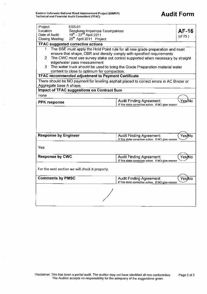


Annex-3 : Attendance Register
Doc. ID: B011 – ESS-01 Audit Report
ANNEX-3 ATTENDANCE REGISTER
Eastern Indonesia National Road Improvement Project (EINRIP)

Annex-4 : Letter No. TFAC 2011/006
Doc. ID: B011 – ESS-01 Audit Report
ANNEX-4 LETTER NO. TFAC 2011/006
‘REQUIRED ENGINEERS ACTION ON WORKS QUALITY DEFICIENCIES’
Eastern Indonesia National Road Improvement Project (EINRIP)

Annex-5 : Corrective Action Priorities
Doc. ID: B011 – ESS-01 Audit Report
ANNEX-5 CORRECTIVE ACTION PRIORITIES
Eastern Indonesia National Road Improvement Project (EINRIP)

Annex-5 : Corrective Action Priorities
Doc. ID: B011 – ESS-01 Audit Report Annex 5 - 1
Table 1 Provisional TFAC Non-Conformity Classes and Degree of Seriousness
Class and degree of
seriousness Description suggested Engineer’s actions Remarks
W (Works)
A
Immediate corrective action is required. Failure to act immediately:
i) will be seriously detrimental to subsequent work and/or to the finished product performance
ii) or will have other unacceptable impacts such as public safety risk
Written instruction to the Contractor for immediate action
Written Rejection notice
No payment until corrective actions have been taken
Reject all Work Requests for other works that will impede repair or will be influenced detrimentally by the rejected work, until corrective action is taken
No payment for works undertaken without an approved Work Request.
Instruct additional Hold Point(s) if necessary
This Class includes all permanent works non-conformities.
B Immediate corrective action is required. Failure to act immediately will to have some detrimental impact on subsequent work and/or to the finished product
Written instruction to the Contractor for immediate action
Reduced payment for that work until corrective actions have been taken
Refuse all work requests for other works that will impede repair or will be influenced detrimentally by the rejected work, until corrective action is taken
Make no payment for works undertaken without an approved Work Request
Apply additional Hold Point(s) if necessary
C Action is required but some delay can be tolerated for example while additional equipment is procured
Written instruction to the Contractor including a time limit for corrective action
Other actions if the contractor fails to comply with the time limit
A temporary Payment reduction may apply
D Action is required but correction before Substantial Completion would be acceptable ie no impact on other works
Written instruction to the Contractor including a time limit for corrective action

Annex-5 : Corrective Action Priorities
Doc. ID: B011 – ESS-01 Audit Report Annex 5 - 2
Class and degree of
seriousness Description suggested Engineer’s actions Remarks
Other actions if the contractor fails to comply with the time limit
Usually no impact on payment
M (Method of
Work)
A Method of Work deficiencies that seriously impact on work quality,
Written instruction to the Contractor including a time limit for corrective action
Refuse Work Requests for all works of that type and for other works detrimentally affected by that work item
1
No payment for works undertaken without a Work Request approval
Formally reject work if necessary undertaken without approval if necessary
Method of Work issues affect all works under a particular Pay Item or related group of pay items. Often Works non conformities are also Method of Work Related.
C
Method of Work deficiencies that never the less permit reasonable delivery of work quality and can therefore be tolerated until equipment resources are improved or until other corrective action is taken
Written instruction to the Contractor including a time limit for corrective action
Other actions will be necessary if the contractor does not comply with the instruction
E (Emergency)
emergency measures that are tolerated because delay resulting from insistence on Contract Compliance would be unacceptable
Written instruction to the contractor
Letter to the Employer explaining the circumstances and impacts
this category should only be applied in exceptional circumstances
.
1 Examples include all asphaltic concrete works if compaction standards are not achieved or all Prime Coat and therefore all Asphaltic Concrete works if the
Bitumen Distributer is seriously non-compliant