earthquakeeffectonundergroundstructures-111006045416-phpapp01
DESCRIPTION
earthquakeTRANSCRIPT

Earthquake Effect on Underground Structures
(Underground Tunnels)
by
AMIR HOSSEIN JODEIRI
In Partial Fulfillment of the Requirements
For the Degree of subject
Earthquake Engineering
MAPUA Institute of Technology
CIVIL ENGINEERING DEPARTMENT
Professor PILONES
SEMESTER (1) 2011- 2012
Abstract
Due to the increasing development of land and construction costs for
each of these structures are just important in the urban transport and the danger of injury
against the risk of earthquake to be studied. A review on the seismic behavior and design of
underground structures in soft ground is described focusing on the development of equivalent
static seismic design called the seismic deformation method. In the past most of the
underground structures were designed without seismic considerations, because generally the
tunnels had a good performance during the earthquakes compared to aboveground structures
behavior.
INTRODUCTION
BACKGROUND
The first part - of the vulnerability of underground structures in earthquake
Why the tunnel?
1 - Shortening and increase the efficiency of traffic
2 - Improve the geometric profile
3 - More safety against earthquake
Damaging agents:
1- Earthquake vibrations
2- Fault
3- Tectonic Uplift and Subsidence
In a broad sense, earthquake effects on underground tunnel structures can be grouped into two
categories – ground shaking and ground failure.
Ground shaking refers to the vibration of the ground produced by seismic waves propagating
through the earth’s crust. Body waves travel within the earth’s material. They may be either
longitudinal P waves or transverse shear S waves and they can travel in any direction in the
ground. Surface waves travel along the earth’s surface. They may be either Rayleigh waves or
Love waves.

Earthquake vibrations:
1-Volume waves PW and SW
2- Surface waves LW and RW
Factors affecting the behavior of the tunnel:
Site condition, Shape and size of the Tunnel, Tunnel depth, Tunnel lining
Failure modes:
Deformation at the Tunnel, Creation of cracks or open joints, falling from the ceiling or walls.
Reduce losses:
Increase the vulnerability of structures to absorb the deformation applied , Appropriate use
of joints at intersections , Avoid direct contact with the layers
of rock tunnel, The rigid parts connected to the main structure must be coordinated with the
main structures are vibrating.
The definition section of Tunnel
Features tunnels and how they are affected by the earthquake Effective. The definitions in this
section of the tunnels and the effect of each vulnerability of the tunnels.
Depth of tunnel:
In general, tunnels, earthquake, other than very superficial structures
stable. The land displacement, range of motion, acceleration and velocity of a particle's
generally increasing with depth, is reduced (particularly if the ground is soft), so
in cases where the acceleration of the earthquake at a depth of 50 meters, 40percent
is woven.
Shape and size of the tunnel
The tunnel cross section is larger, the sensitivity It is the most earthquake. One of
the great tunnels being localized at the inter sections and Metro stations . There are usually two
or more together in the tunnel the focus will be tunnels, causing tensions between
the static environments. In this case when seismic waves pass through a tension that is
happening.

How to make a huge impact on the vulnerability of seismic waves, because the method of
excavation, the soil stays completely intact and the other of these tunnels are usually built
where the depth of the tunnel is large. After excavation of the tunnel lining to protect against
loss if used. Of course there are also cases where the rocks have enough strength, the cover is
not used, but otherwise allowing the use of Shotcrete, concrete in situ, or are pre-built
components.
Scope of this Study
The work performed to achieve these goals consisted of:
A summary of observed earthquake effects on underground structures.
A review of current seismic design methodology for both circular mined tunnels.
Overview
Discussions of the earthquake shaking effect on underground tunnels
The response of tunnels to seismic shaking motions may be demonstrated in terms of types of
deformations. (Axial, Curvature).
OBJECTIVE
The main objective of the research is to develop a simplified, though accurate, approach to
estimate the earthquake-induced stress increments on tunnel lining. The purpose of this
research study was to develop a rational and consistent seismic design methodology for tunnels
that would also be applicable to other underground structures.
Methodology
Seismic vibrations of the tunnels
Most tunnel structures were designed and built, however, without regard to seismic effects.
Which are usually stimulated by the earthquake slip, especially in the input - output tunnels are
a lot of damage to underground spaces to enter. Many reports of earthquake damage to
underground spaces, through the tunnels have been a slip of the entries. Liquefaction of the
ground, especially if the sediments have a high percentage of loose sand and silt was
constructed; it can damage a lot of space on the ground.
The importance of earthquake vibrations
Burst damage (such as faulting or landslides) in certain areas that can occur with detailed
studies of geological engineering in these areas are identified and measures can be considered,
but the vibration caused by the fault movement at a distance or close to the underground space
and its severity can vary greatly. If the directions of the waves, with miles of tunnels or tunnel
axis may shift again in other forms of underground space will be created. While the disruption
caused by faulting or landslides are usually transformed to the Site Survey is predictable.
The analysis effect of waves on the underground structure
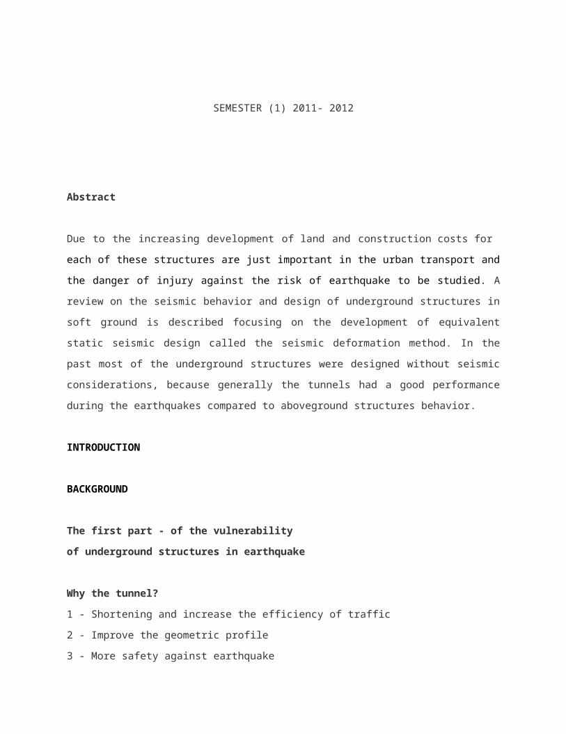
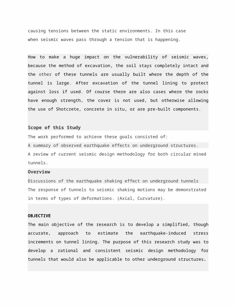
1- Pressure waves:
PW pressure waves with a horizontal shear waves, PW. HSW vertical component
pressure waves are a central component. PW on underground structures creates a
longitudinal strain and tension. Pw is the fastest seismic waves spread out. So the first
wave of the site will affect the soil structure.
Refer: 2
2- Vertical shear waves :
The main types of vertical shear waves are waves which include approximately two thirds
of energy are released. Structures and systems are the vertical displacement.
Refer: 2
3- Riley waves :
Riley in the waves, the particles at the top of their rotation, the wave is moving in the
opposite direction and movement of particles on the surface of the large diameter of the
ellipse that is perpendicular to wave propagation. Riley as vertical shear waves for large wave
structure function. Undergoing a shift underground system is acting based on their height.
Refer: 2
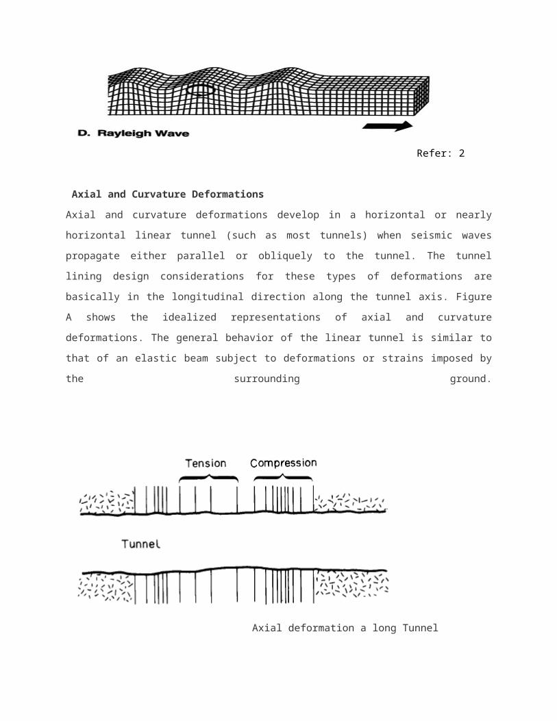
Axial and Curvature Deformations
Axial and curvature deformations develop in a horizontal or nearly horizontal linear tunnel (such
as most tunnels) when seismic waves propagate either parallel or obliquely to the tunnel. The
tunnel lining design considerations for these types of deformations are basically in the
longitudinal direction along the tunnel axis. Figure A shows the idealized representations of axial
and curvature deformations. The general behavior of the linear tunnel is similar to that of an
elastic beam subject to deformations or strains imposed by the surrounding ground.
Axial deformation a long Tunnel
Fig A.
Refer:1
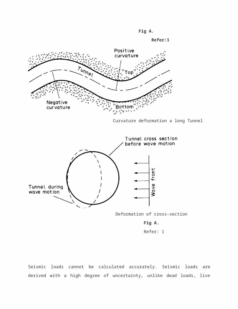
Curvature deformation a long Tunnel
Deformation of cross-section
Fig A.
Refer: 1
Seismic loads cannot be calculated accurately. Seismic loads are derived with a high degree of
uncertainty, unlike dead loads, live loads, or other effects such as temperature changes. Any
specified seismic effect has a risk (probability of exceedance) associated with it.
Overlying of Tunnel section Racking of Tunnel section
Deformation modes of tunnels due to seismic waves
Refer: 1
Seismic soil deformation
Two types of deformation can be obtained from the earthquake on the underground transport
systems, which include shear deformation and curvature deformation. Direct exposure of the
soil local curvature deformation curve (the earthquake) on underground structures arises.
Underground structures must have the capacity to absorb the resulting strain. Shear
deformation as well as the time delay in response to an acceleration of the incoming base is the
bedrock.
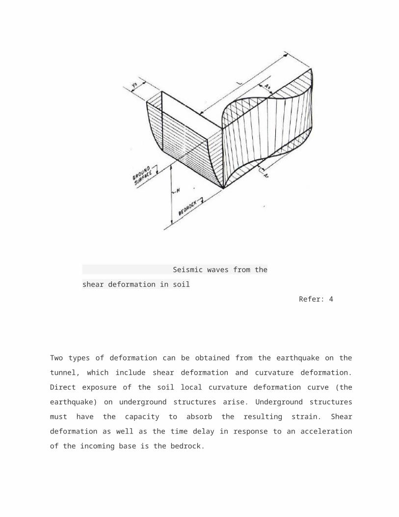
Seismic waves from the shear deformation in soil
Refer: 4
Two types of deformation can be obtained from the earthquake on the tunnel, which include
shear deformation and curvature deformation. Direct exposure of the soil local curvature
deformation curve (the earthquake) on underground structures arise. Underground structures

must have the capacity to absorb the resulting strain. Shear deformation as well as the time
delay in response to an acceleration of the incoming base is the bedrock.
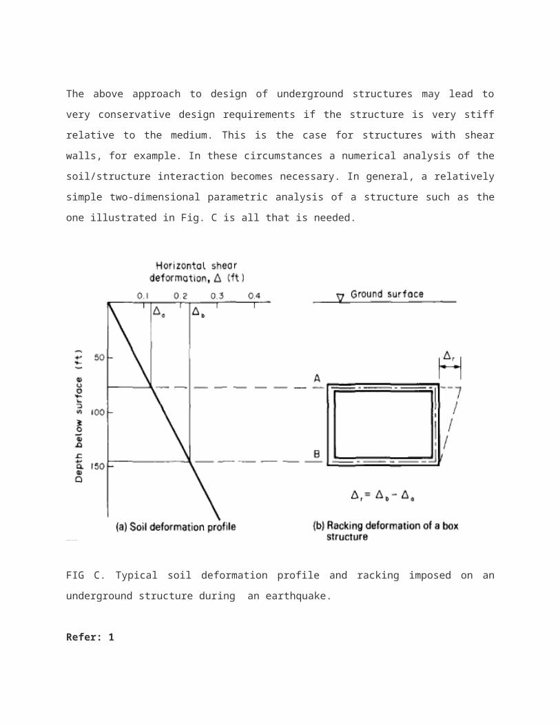
The above approach to design of underground structures may lead to very conservative design
requirements if the structure is very stiff relative to the medium. This is the case for structures
with shear walls, for example. In these circumstances a numerical analysis of the soil/structure
interaction becomes necessary. In general, a relatively simple two-dimensional parametric
analysis of a structure such as the one illustrated in Fig. C is all that is needed.
FIG C. Typical soil deformation profile and racking imposed on an underground structure during
an earthquake.
Refer: 1
Loading Criteria
Maximum Design Earthquake (MDE). Given the performance goals of the MDE the
recommended seismic loading combinations using the load factor design method are as follows:

For Cut-and-Cover Tunnel Structures:
U = D + L + E1+ E2 +EQ (Eq. 1)
Where U = required structural strength capacity
D = effects due to dead loads of structural components
L = effects due to live loads
E1 = effects due to vertical loads of earth and water
E2 = effects due to horizontal loads of earth and water
EQ = effects due to design earthquake (MDE)
For Mined (Circular) Tunnel Lining
Where U, D, L, and EQ are as defined in Equation 1
EX = effects of static loads due to excavation
H = effects due to hydrostatic water pressure
The structure should first be designed with adequate strength capacity under static
Loading conditions.
The structure should then be checked in terms of ductility as well as strength when
Earthquake effects, EQ, are considered. The “EQ” term for conventional surface
Structure design reflects primarily the inertial effect on the structures. For tunnel
Structures, the earthquake effect is governed by the displacements/deformations
Imposed on the tunnels by the ground.
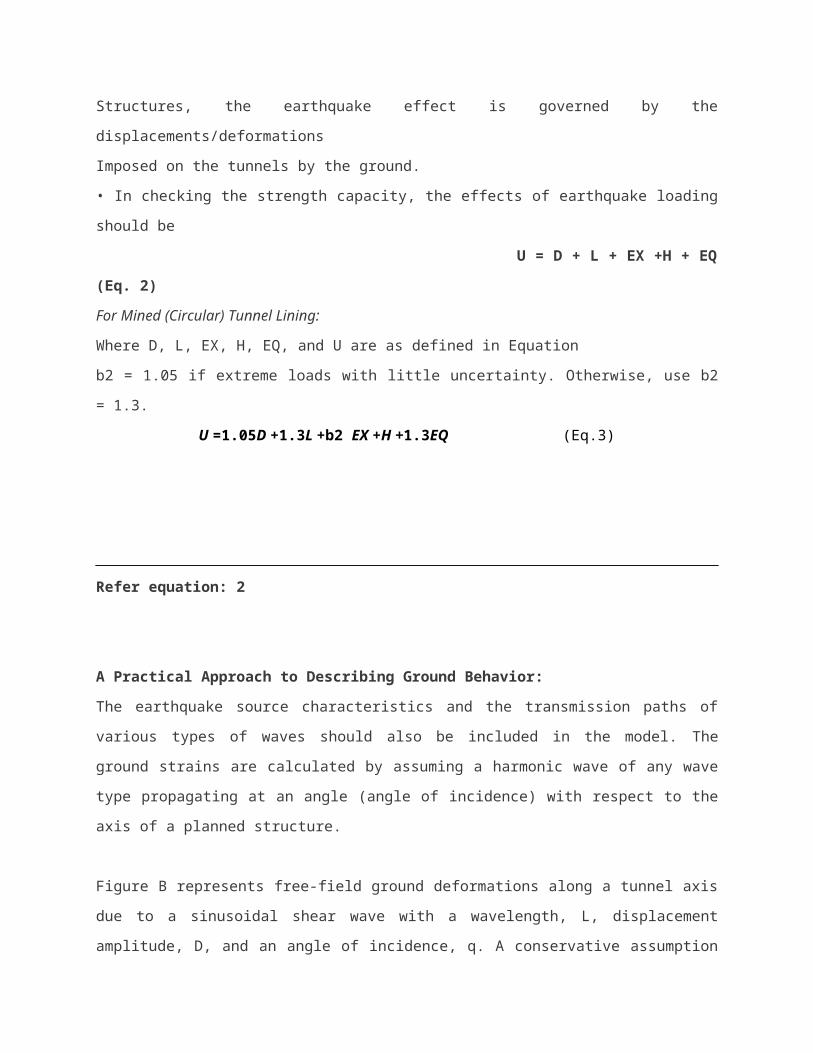
• In checking the strength capacity, the effects of earthquake loading should be
U = D + L + EX +H + EQ (Eq. 2)
For Mined (Circular) Tunnel Lining:
Where D, L, EX, H, EQ, and U are as defined in Equation
b2 = 1.05 if extreme loads with little uncertainty. Otherwise, use b2 = 1.3.
U =1.05D +1.3L +b2 EX +H +1.3EQ (Eq.3)
Refer equation: 2
A Practical Approach to Describing Ground Behavior:
The earthquake source characteristics and the transmission paths of various types of waves
should also be included in the model. The ground strains are calculated by assuming a
harmonic wave of any wave type propagating at an angle (angle of incidence) with respect to
the axis of a planned structure.
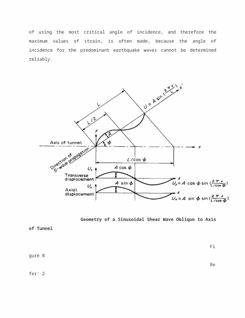
Figure B represents free-field ground deformations along a tunnel axis due to a sinusoidal shear
wave with a wavelength, L, displacement amplitude, D, and an angle of incidence, q. A
conservative assumption of using the most critical angle of incidence, and therefore the
maximum values of strain, is often made, because the angle of incidence for the predominant
earthquake waves cannot be determined reliably.
Geometry of a Sinusoidal Shear Wave Oblique to Axis of Tunnel
Figure B
Refer: 2
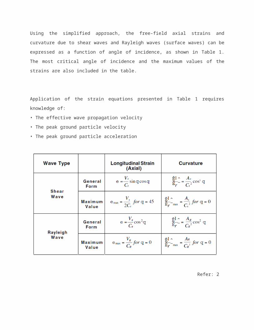
Using the simplified approach, the free-field axial strains and curvature due to shear waves and
Rayleigh waves (surface waves) can be expressed as a function of angle of incidence, as
shown in Table 1. The most critical angle of incidence and the maximum values of the strains
are also included in the table.
Application of the strain equations presented in Table 1 requires knowledge of:
• The effective wave propagation velocity
• The peak ground particle velocity
• The peak ground particle acceleration
Refer: 2
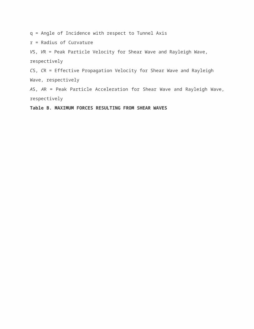
q = Angle of Incidence with respect to Tunnel Axis
r = Radius of Curvature
VS, VR = Peak Particle Velocity for Shear Wave and Rayleigh Wave, respectively
CS, CR = Effective Propagation Velocity for Shear Wave and Rayleigh Wave, respectively
AS, AR = Peak Particle Acceleration for Shear Wave and Rayleigh Wave, respectively
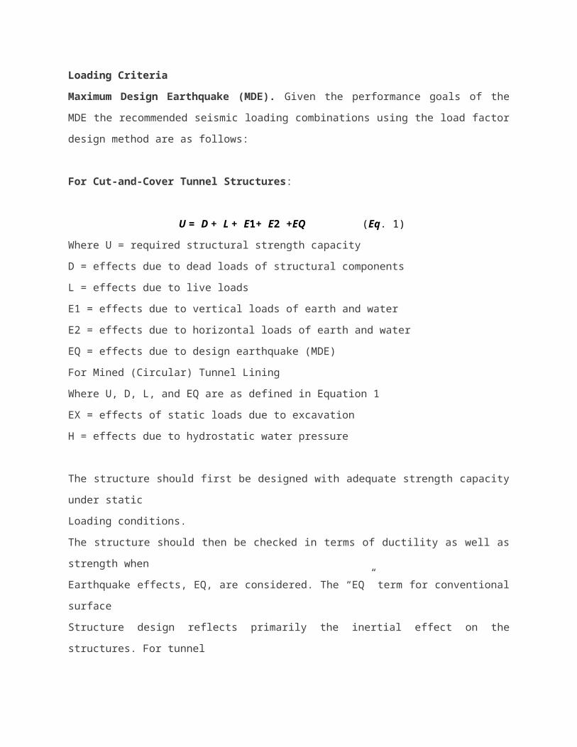
Table B. MAXIMUM FORCES RESULTING FROM SHEAR WAVES
Refer : 2
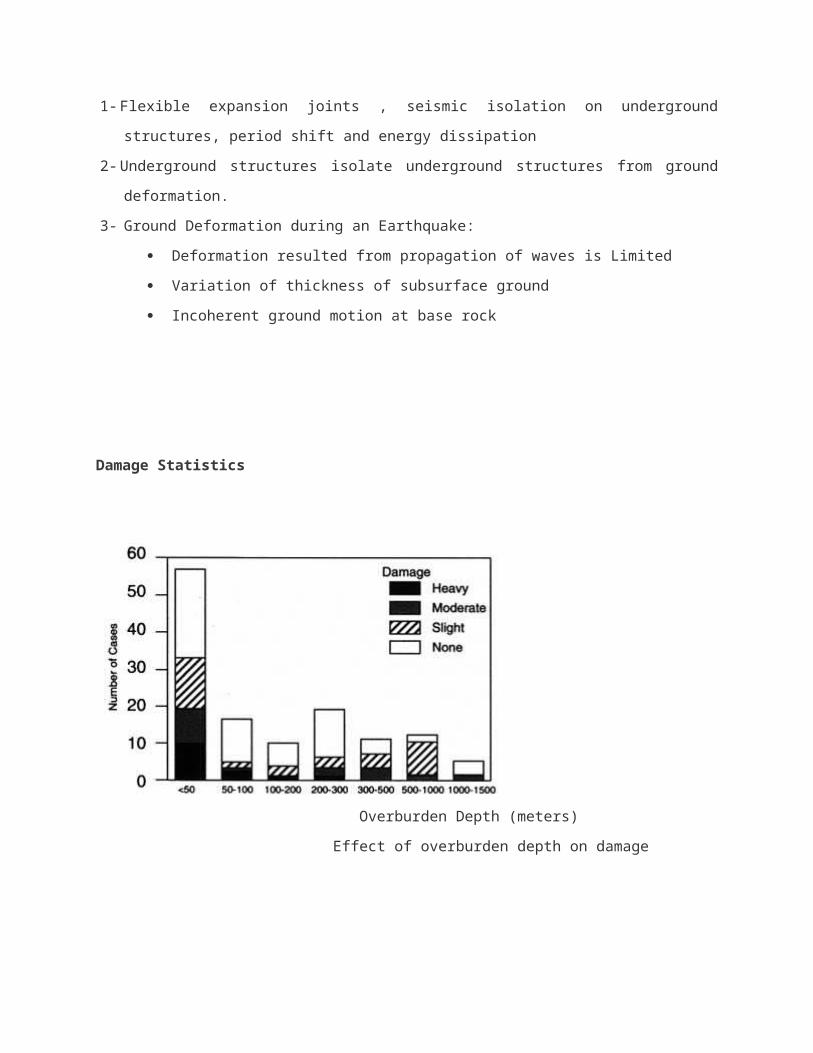
Measures for mitigating seismic effect on underground structures :
1- Flexible expansion joints , seismic isolation on underground structures, period shift and
energy dissipation
2- Underground structures isolate underground structures from ground deformation.
3- Ground Deformation during an Earthquake:
Deformation resulted from propagation of waves is Limited
Variation of thickness of subsurface ground
Incoherent ground motion at base rock
Damage Statistics
Overburden Depth (meters)
Effect of overburden depth on damage
Type of surrounding hock
Effect of surrounding rock type on damage
Richter Magnitude
Effects of earthquake magnitude on damage
COMPARISON BETWEEN SEISMIC AND STATIC FORCES AND DEFORMATIONS OF A
CIRCULAR TUNNEL
In these analyses the dimensions and material properties of the lined tunnel are:
M2/m, lining diameter: 6m, El = 24,840,000 KN/m2 and thickness of the overburden = 15m
And l ϑ = 0.2
Earthquake and ground parameters:
Young’s modulus (Em):100000-676,000 KN/m2, Gm = 38461.56-260000 KN/m2, γ max =
0.001626-0.004229, ϑ m = 0.3, γ t = 1.7 KN/m3 and Vs = 0.63 m/s and as = 0.45g.
The result of these analyses were compared and summarized as follows:
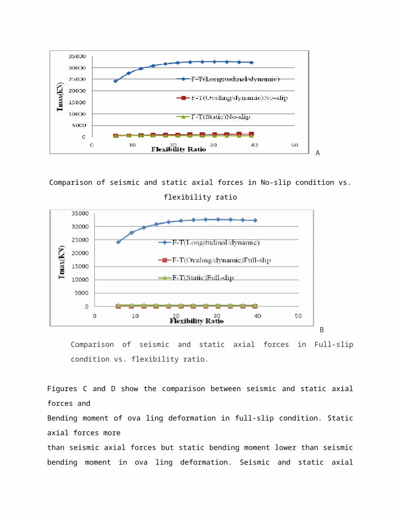
1) According to Figures A,B through 9, seismic axial forces and bending moment of longitudinal
deformation are much more than seismic and static axial forces and bending moment of
deformation in both no-slip and full-slip conditions. So that tunnels must be designed for
dynamic loading. Also these figures show that seismic forces of longitudinal deformation
increase by increasing flexibility ratio but seismic bending moment of this deformation
decreases by increasing flexibility ratio.
A
Comparison of seismic and static axial forces in No-slip condition vs. flexibility ratio
B
Comparison of seismic and static axial forces in Full-slip condition vs. flexibility ratio.
Figures C and D show the comparison between seismic and static axial forces and
Bending moment of ova ling deformation in full-slip condition. Static axial forces more
than seismic axial forces but static bending moment lower than seismic bending moment in ova
ling deformation. Seismic and static axial forces and bending moment of ova ling deformation
decrease by increasing flexibility ratio.
C
Comparison of seismic and static bending moment of deformation in full slip
Condition vs. flexibility ratio.

D
comparison of seismic and static axial forces of deformation in full-slip condition vs. flexibility ratio.
Comparison between seismic forces of longitudinal deformation and static forces show
that seismic forces of longitudinal deformation are much more than static forces , thus
lining of tunnels must be designed for dynamic loadings. Also dynamic axial forces and
bending moment are much more than static axial forces and bending moment while
overburden increases.
REFERENCE A, B, C, and D: Comparison between seismic and static analyses of
tunnels. Rock Mechanics, Fuenkajorn & Phien-wej (eds) 2009. ISBN 978 974 533
624 7
CONCLUSION
In the past most of the underground structures were designed without seismic considerations,
because generally the tunnels had a good performance during the earthquakes compared to
aboveground structures behavior.
Performance -based seismic design should be aimed both to maintain in operation the tunnels
during the more frequent events (of lower intensity) and to avoid human life losses for
exceptional earthquakes (of higher intensity), according to the local seismic hazard predictions.
In some cases, and almost always in presence of ground discontinuity, structural discontinuity
or high potential of ground failure, protecting measures need to be carefully designed.
REFERENCE
1- A seismic Design of Underground Structures C. M. St John and T. F. Zahrah
Tunneling and Underground Space Technology, Vol. 2, No. 2, pp. 165-197, 1987.
2- Seismic Design of Tunnels Jaw-Nan (Joe) Wang, Ph.D., P.E. Professional Associate Parsons Brinckerhoff Quade & Douglas, Inc. June 1993.
3-Comparison between seismic and static analyses of tunnels. Rock Mechanics, Fuenkajorn & Phien-wej (eds) 2009. ISBN 978 974 533 624 7
4 - Mirmirani, Shahriar. Effect of earthquakes on the tunnels, the fifth Conference of the tunnel 7
to 9 November 2010 Faculty of Engineering of Iran, Tehran University, pages 201 to 207
Appendix
SHAKE TABLE TESTING TO QUANTIFY SEISMIC SOIL-STRUCTURE-
INTERACTION OF UNDERGROUND STRUCTURES
This research uses shake table testing of scale soil-structure models to mimic the coupled
seismic response of underground structures and surrounding/supporting soil (termed soil-
structural-interaction or SSI). Currently the seismic design of subways and other critical
underground infrastructure rely on little to no empirical data for calibrating numerical
simulations. This research is working towards filling that empirical data gap. The research is
composed of two phases, the first a validation of the free-field response of a flexible wall barrel

filled with model soil, the second a test to measure the “racking” deformations induced in a
model subway cross-section embedded in the model soil.
This research project targets the seismic design of subways and other similar underground
structures. A scale model testing platform has been developed for 1D shake table tests
That mimics the dynamic free-field conditions of a soil column of soft cohesive soil subjected to
seismic loading. In this soil column a model structure is embedded to measure what are
Commonly called “racking” deformations or deformations of the top with respect to the bottom
of the embedded structure the stiffness ratio of the soil to the structure results in the soil-
Structure -interaction. These measured “racking” deformations will be modeled numerically
using equivalent linear (FLUSH) and non-linear (ABAQUS) soil-structure-interaction programs
to expand the applicability of the empirical results.
TESTING PLATFORM
In physical testing, and scale model testing in particular, the testing equipment and physical
model details can demand the bulk of the research efforts. This project is no exception. The first
year of this project was spent acquiring the necessary materials, fabricating and modifying the
testing equipment, and calibrating the testing platform.
The central piece of testing equipment is a flexible wall barrel that mimics free-field seismic site
response when subjected to shaking on the shake table. Validation of the testing platform
involves comparing analytical results with recorded response from the flexible wall barrel.
Figures 1 and 2 show the validation by Meymand (1998) demonstrating the dynamic
performance of the flexible barrel versus other testing containers. As can be seen the flexible
wall barrel provides the most accurate representation of seismic soil response with respect to
the prototype soil column as modeled numerically using QUAD4M (Hudson et al. 1994).
Figure 1. Different model soil containers for SSI shake table testing (after Meymand 1998).
Figure 2. Dynamic analysis of different model soil containers. showing that the flexible wall
barrel provides the most realistic response when compared to prototype field conditions (after
Meymand 1998).
The flexible wall barrel and associated equipment was assembled on the 1D shake table in the
Parsons Earthquake Lab at Cal Poly, and the mixing of an appropriate model soil was carried
out. Figure 3 shows the flexible wall barrel assembled on the shake table awaiting the model
soil. Figure 4 shows the filling of the barrel and Figure 5 shows the full barrel awaiting shake
table testing.
Figure 3. Testing platform showing the shake table with the flexible wall barrel. The flexible wall
barrel is composed of the four corner posts with universal joints at the top and bottom, the top
and bottom rings, and the barrel wall. The wall is composed of a 6.4 mm thick rubber membrane
which is confined by 45 mm wide Kevlar straps spaced on center every 60 mm. The (yellow)
mixer on the left is used to mix the large volumes of model soil (composed of kaolinite,
bentonite, fly ash, and water).
The Parsons Earthquake Lab at Cal Poly has a 1D shake table with a 9000 kg payload capacity.
Under the maximum payload the table can accelerate up to 1g, has a maximum velocity of 97
cm/sec, a maximum peak to peak displacement of 25 cm, and operates in the frequency range
of 0.1 to 50 Hz. A full flexible wall barrel and accompanying equipment is estimated to weigh on
the order of 7000 kg.

Figure 4. Process of filling the barrel with scale model soil Ten accelerometers were placed in
the soil lifts in both vertical and horizontal arrays to record the dynamic response of the soil
during shaking.
Figure 5. Shown is a full barrel being prepared for initial calibration tests. Note the cross bracing
still in place that will be removed prior to testing to allow the flexible wall barrel free movement in
response to the imposed shaking.
Figure 6 shows the plan view layout of the accelerometer array and the T-bar locations. The
accelerometers arrangement is composed of a central array to measure the average model soil
column response, an off center array in anticipation for the second phase of the test when the
model subway cross-section will be embedded in the soil column, and accelerometers near the
edges to measure any boundary effects due to the flexible wall barrel assembly.
Figure 6. Top down plan view of the flexible wall barrel showing the accelerometer array
layout, T-bar locations, and radial dimensions.
PHASE 1 TESTING
The first phase was to perform free-field tests to measure the dynamic response of the soil
column without the influence of the underground structure and provide a baseline for evaluating
the effects of the soil on the structure. The ground motions selected for table input are;
1. 1979 Imperial Valley, El Centro motion
2. 1992 Landers, Joshua Tree motion
3. 1999 Chi Chi, TCU075 motion
These motions were selected specifically to impose large adverse loads on an underground
structure. These were also the same motions selected and peer reviewed for a tunnel related
consulting project similar to the subway prototype.
PHASE 2 TESTING
An underground section of the BART (Bay Area Rapid Transit) light rail was chosen as the
prototype tunnel cross-section for the SSI tests. This structure is also similar to light rail tunnels
being considered in the Jiangsu province of China. A scale model structure adhering to the
similitude scaling of the structural stiffness of the BART tunnel cross section was assembled.
Figure 7. Shear wave velocity profile from Phase 1 tests. Shear wave velocity was
measured using top down hammer blows and correlated estimates from bottom up T-bar
tests.
Figure 8. Comparison of the free-field flexible barrel recording at the model soil surface
versus SHAKE results of the prototype soil profile. The input motion here is the 1979
Imperial Valley El Centro 180 recording.
This manuscript presents research delving into the seismic soil-structure-interaction
(SSI) of a subway in soft clayey soil. The goal of this research is to provide an empirical
basis for the “racking” deformations that are a design reality of underground SSI
projects. A 1g tenth scale model testing platform was developed for dynamic testing on
the shake table. The platform is composed of a flexible wall barrel, scale model soil, and
associated testing hardware. The first phase of the research, free-field testing, was
completed by the time of manuscript submission. The response of the flexible wall barrel
testing platform is shown in Figure 8 to adequately mimic the prototype soil column as
validated using 1D equivalent linear (SHAKE) numerical analysis.