earth retaining walls and structures - online-pdh
TRANSCRIPT

Earth Retaining Walls and
Structures
DISCLAIMER:
All course materials available on this website are not to be construed as a representation or warranty on the part of Online-PDH, or other persons
and/or organizations named herein. All course literature is for reference purposes only, and should not be used as a substitute for competent,
professional engineering council. Use or application of any information herein, should be done so at the discretion of a licensed professional
engineer in that given field of expertise. Any person(s) making use of this information, herein, does so at their own risk and assumes any and all
liabilities arising therefrom.
Copyright © 2009 Online-PDH - All Rights Reserved
1265 San Juan Dr. - Merritt Island, FL 32952
Phone: 321-501-5601
Online Continuing Education for Professional Engineers
Since 2009
PDH Credits:
5 PDH
Course No.:
ERS101
Publication Source:
Original Courseware By Donald W. Parnell, PE
Release Date:
April 2018

Earth Retaining Walls and Structures Credits: 5 PDH
Course Description
This course is intended as an introduction to earth retention, for the non-geotechnical engineer. The main objective of this course is to provide an overview of the principles of earth retention, earth retaining walls and other structures; plus various methods used to retain soil mass. There is also a basic introduction to basic soil mechanics principles, and the in-situ and laboratory soil testing procedures used to evaluate soil conditions at the site. Also covered are two common theories used for wall failure analysis (Rankine and Coulomb), and a case study of a wall failure highlighting some of the primary reasons for wall failure.
Topics
Overview of Earth Retention Structures
Uses of Retaining Walls
Types of Retaining Walls
Wall Anchoring & Remediation
Materials used in Retaining Wall Construction
Batter Walls and Tiered Walls
Proportioning - Using Proper Wall Proportions
Basic Soil Mechanics Principles, Basic Soil Classification
Cases of Lateral Earth Pressure; Hydrostatic Pressure
Surcharge and Seismic Loading
Backfill Soil Analysis and Evaluation
Soil Compaction and Consolidation
Drainage Systems
Failure Analysis, Factors of Safety, Rankin and Coulomb Theory
In-situ and Laboratory Soil Testing Procedures
Case study of a wall failure situation
Online-PDH
1265 San Juan Dr. Merritt island, FL 32952
Original Courseware by:
Donald W. Parnell, PE All Rights Reserved
Chapter One – Retaining
Structures
Course Overview
Definition of a Retaining Structure
When discussing the concept of a retaining “wall”, we may be referring to any vertical or nearly vertical-planed structure whose purpose is to retain a soil mass, and resist lateral earth pressures. An earth retention structure could be a short, medium, or tall wall, a basement wall, or internally stabilized earth retention systems such as those which use tiebacks with anchors, soil nailing, and other mechanically stabilized and reinforced earth systems.
Stabilized Walls
Stabilized walls can be classified as either internally-stabilized or externally-stabilized structures or systems.
Internally stabilized walls - are supported by the soil friction between the support members and the soil (backfill and in-situ).
Externally stabilized walls - are supported by means outside the soil mass such as struts, or within the wall itself such as reinforcing or gravitation force.
Types of Earth Pressures
In this course, we’ll also discuss the three types of laterally acting earth pressures (at-rest, active, and passive) as they apply to retaining wall design. Additionally, we will discuss some basic soil mechanics principles, along with some common field and laboratory soil testing procedures.
Factors of Safety
We will also briefly cover the methods used for calculating the factors of safety for sliding, overturning, bearing capacity, and shallow/deep shear failure modes.
Case Study
In addition, we will examine a case study of a wall failure situation which includes many of the common pitfalls of wall design, such as the effects of surcharge and hydrostatic loads on a wall, and the importance of preemptive stabilization remediation on aging structures.
Retaining Walls
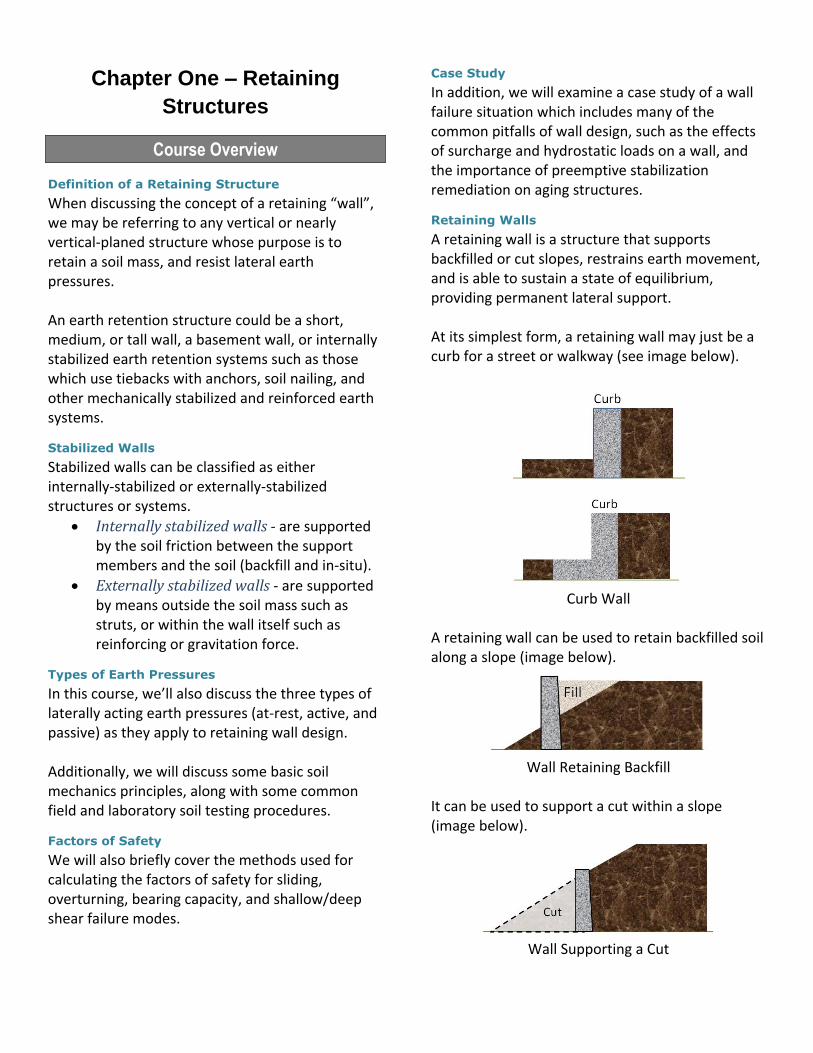
A retaining wall is a structure that supports backfilled or cut slopes, restrains earth movement, and is able to sustain a state of equilibrium, providing permanent lateral support. At its simplest form, a retaining wall may just be a curb for a street or walkway (see image below).
Curb Wall
A retaining wall can be used to retain backfilled soil along a slope (image below).
Wall Retaining Backfill
It can be used to support a cut within a slope (image below).
Wall Supporting a Cut
It can allow for a change of grade, or change of angle along that slope (image below).
Wall Facilitating a Change of Grade or Slope
Types of Retaining Walls
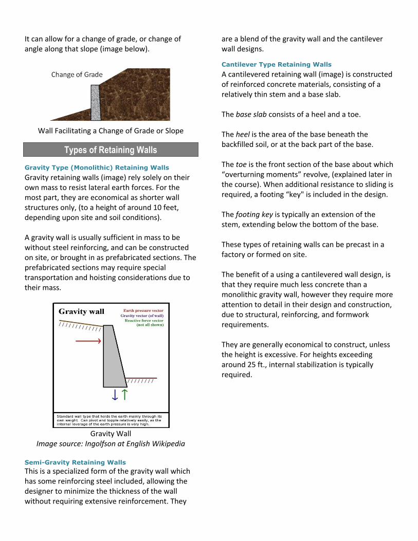
Gravity Type (Monolithic) Retaining Walls
Gravity retaining walls (image) rely solely on their own mass to resist lateral earth forces. For the most part, they are economical as shorter wall structures only, (to a height of around 10 feet, depending upon site and soil conditions). A gravity wall is usually sufficient in mass to be without steel reinforcing, and can be constructed on site, or brought in as prefabricated sections. The prefabricated sections may require special transportation and hoisting considerations due to their mass.
Gravity Wall
Image source: Ingolfson at English Wikipedia Semi-Gravity Retaining Walls
This is a specialized form of the gravity wall which has some reinforcing steel included, allowing the designer to minimize the thickness of the wall without requiring extensive reinforcement. They
are a blend of the gravity wall and the cantilever wall designs.
Cantilever Type Retaining Walls
A cantilevered retaining wall (image) is constructed of reinforced concrete materials, consisting of a relatively thin stem and a base slab. The base slab consists of a heel and a toe. The heel is the area of the base beneath the backfilled soil, or at the back part of the base. The toe is the front section of the base about which “overturning moments” revolve, (explained later in the course). When additional resistance to sliding is required, a footing “key" is included in the design. The footing key is typically an extension of the stem, extending below the bottom of the base. These types of retaining walls can be precast in a factory or formed on site. The benefit of a using a cantilevered wall design, is that they require much less concrete than a monolithic gravity wall, however they require more attention to detail in their design and construction, due to structural, reinforcing, and formwork requirements. They are generally economical to construct, unless the height is excessive. For heights exceeding around 25 ft., internal stabilization is typically required.

Cantilever Wall
Image source: Ingolfson at English Wikipedia
Counterfort retaining walls
These walls are similar to the cantilever walls with the exception that they have thin vertical concrete webs (counterforts) at regular intervals along the backside of the wall. The counterfort webs tie the stem and base together, with the purpose of reducing the shear forces and bending moments imposed upon the wall by the soil.
Pre-Cast Concrete Counterfort Retaining Wall Image Source: designerpropertiestexas.com
Additionally, the counterforts increase the weight of the wall due to this added concrete mass. Counterfort walls are similar to gravity, and cantilevered, in that they can be precast off site (image), or formed on site. When wall heights begin to reach excessive heights, the counterfort
retaining wall has economic benefits over the cantilever wall.
Buttress Wall
A buttress wall (image) is similar in nature to the counterfort wall, with the exception of having the support webs on the front face of the wall instead of the back face, acting as a compression strut. This wall is a fine example of external stabilization.
Culross Palace Gardens - Buttress Wall
Image Source: Dr. Richard Murray
Prefabricated Interlocking Block Walls
Interlocking masonry blocks (image) are a popular choice with the DIY retaining wall builder and professional builder alike. These masonry units usually have a flange in the back (depending upon the specific design), which when stacked properly, works as a built in “key” which prevents sliding, and creates a batter effect (inward wall slope). These building units work well, when layers of geotextiles are incorporated between compacted lifts of backfill, located at every few courses of block.
Prefab Blocked Wall
Image Source: Familyhandyman.com
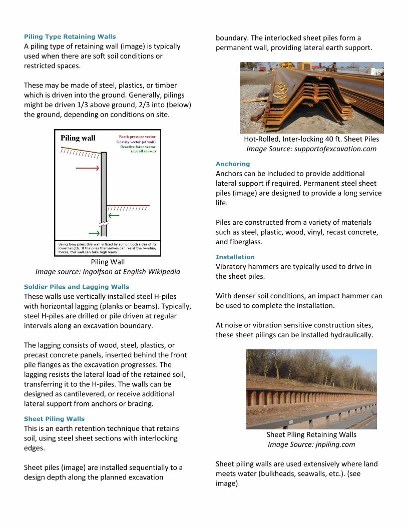
Piling Type Retaining Walls
A piling type of retaining wall (image) is typically used when there are soft soil conditions or restricted spaces. These may be made of steel, plastics, or timber which is driven into the ground. Generally, pilings might be driven 1/3 above ground, 2/3 into (below) the ground, depending on conditions on site.
Piling Wall
Image source: Ingolfson at English Wikipedia
Soldier Piles and Lagging Walls
These walls use vertically installed steel H-piles with horizontal lagging (planks or beams). Typically, steel H-piles are drilled or pile driven at regular intervals along an excavation boundary. The lagging consists of wood, steel, plastics, or precast concrete panels, inserted behind the front pile flanges as the excavation progresses. The lagging resists the lateral load of the retained soil, transferring it to the H-piles. The walls can be designed as cantilevered, or receive additional lateral support from anchors or bracing.
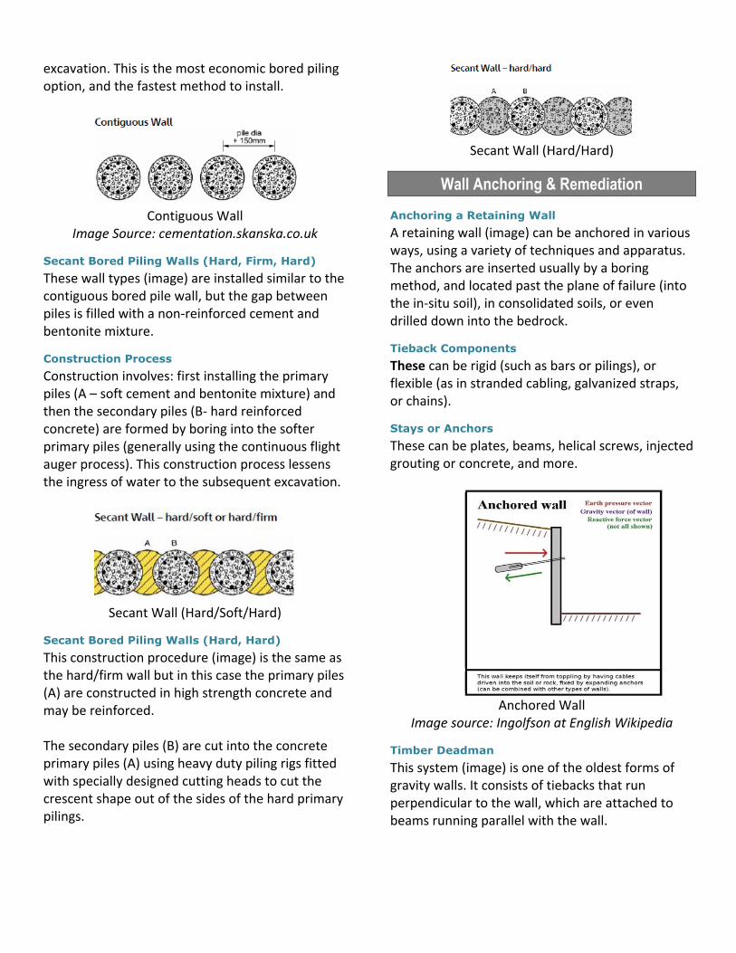
Sheet Piling Walls
This is an earth retention technique that retains soil, using steel sheet sections with interlocking edges. Sheet piles (image) are installed sequentially to a design depth along the planned excavation
boundary. The interlocked sheet piles form a permanent wall, providing lateral earth support.
Hot-Rolled, Inter-locking 40 ft. Sheet Piles Image Source: supportofexcavation.com
Anchoring
Anchors can be included to provide additional lateral support if required. Permanent steel sheet piles (image) are designed to provide a long service life. Piles are constructed from a variety of materials such as steel, plastic, wood, vinyl, recast concrete, and fiberglass.
Installation
Vibratory hammers are typically used to drive in the sheet piles. With denser soil conditions, an impact hammer can be used to complete the installation. At noise or vibration sensitive construction sites, these sheet pilings can be installed hydraulically.
Sheet Piling Retaining Walls Image Source: jnpiling.com
Sheet piling walls are used extensively where land meets water (bulkheads, seawalls, etc.). (see image)

Seawall
Image Source: landandseamarine.com
Driving Methods for Sheet Piles
Pitch and Drive
(for loose soils and short piles) Pitch and drive is the simplest method for sheet pile driving involving driving each sheet pile to full depth before pitching the next.
Panel Driving
(for dense sands and stiff cohesive soils or in the case of potential obstructions) Panel driving is used to ensure that the sheet piles are driven with good vertical alignment. An entire panel of piles is pitched. When obstructions are met, individual piles can be left high without disruption to the overall efficiency.
Staggered Driving
(for problematic soil conditions) In difficult soil conditions, a staggered driving sequence is used. Piles are installed between guide frames and then driven in short sequential steps: piles 1, 3 and 5 first, then piles 2 and 4. Bored Piling Walls This is a method that involves boring a circular hole into the ground, installing steel reinforcement, and filling the bore hole with concrete to form a completed pile. The boring is drilled to the required depth by means of either a crawler crane-mounted rotary boring unit, or a hydraulic based drilling machine.
Bored pile retaining walls may also include a system of earth anchors, reinforcement beams, soil improvement operations (grouting, etc.) and shotcrete reinforcement layer. This construction technique tends to be used in situations where sheet piling is a valid option, but where the vibration or noise levels created by pile driving equipment are not allowed. Bored cast in-situ piles are frequently used as an efficient and economic means of constructing temporary or permanent retaining walls. These techniques are suitable for the provision of deep basements, underground structures and motorway cuttings where working space is limited or adjacent existing structures require restraint. They avoid excessive bulk excavation and help to control ground movements. The choice of a particular system is influenced by a number of factors:
soil type (granular or cohesive, soft or stiff)
ground water profile (perched, high level)
maximum retained heights
construction time available
propping requirements
cost
life span There are three distinct bored pile wall options in current use:
Contiguous wall
Secant wall – hard/soft or hard/firm
Secant wall – hard/hard
Contiguous Pile Walls
Contiguous wall types (image) are installed leaving small gaps (around 6 inches or 150mm), in the structural wall where soil is exposed during the excavation process. This retaining wall option is best suited for retaining soil that is usually firm to stiff (but not granular) and where the ground water table does not rise above the level of the maximum
excavation. This is the most economic bored piling option, and the fastest method to install.
Contiguous Wall
Image Source: cementation.skanska.co.uk
Secant Bored Piling Walls (Hard, Firm, Hard)
These wall types (image) are installed similar to the contiguous bored pile wall, but the gap between piles is filled with a non-reinforced cement and bentonite mixture.
Construction Process
Construction involves: first installing the primary piles (A – soft cement and bentonite mixture) and then the secondary piles (B- hard reinforced concrete) are formed by boring into the softer primary piles (generally using the continuous flight auger process). This construction process lessens the ingress of water to the subsequent excavation.
Secant Wall (Hard/Soft/Hard)
Secant Bored Piling Walls (Hard, Hard)
This construction procedure (image) is the same as the hard/firm wall but in this case the primary piles (A) are constructed in high strength concrete and may be reinforced. The secondary piles (B) are cut into the concrete primary piles (A) using heavy duty piling rigs fitted with specially designed cutting heads to cut the crescent shape out of the sides of the hard primary pilings.
Secant Wall (Hard/Hard)
Wall Anchoring & Remediation
Anchoring a Retaining Wall
A retaining wall (image) can be anchored in various ways, using a variety of techniques and apparatus. The anchors are inserted usually by a boring method, and located past the plane of failure (into the in-situ soil), in consolidated soils, or even drilled down into the bedrock.
Tieback Components
These can be rigid (such as bars or pilings), or flexible (as in stranded cabling, galvanized straps, or chains).
Stays or Anchors
These can be plates, beams, helical screws, injected grouting or concrete, and more.
Anchored Wall
Image source: Ingolfson at English Wikipedia
Timber Deadman
This system (image) is one of the oldest forms of gravity walls. It consists of tiebacks that run perpendicular to the wall, which are attached to beams running parallel with the wall.
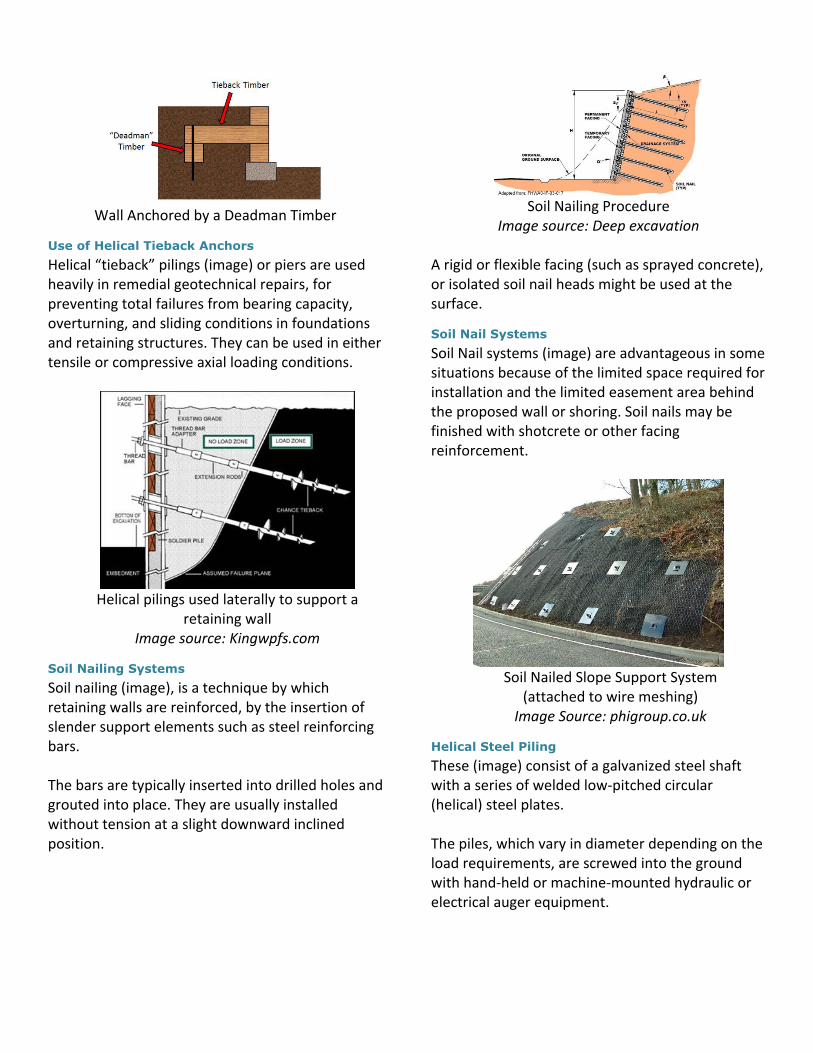
Wall Anchored by a Deadman Timber
Use of Helical Tieback Anchors
Helical “tieback” pilings (image) or piers are used heavily in remedial geotechnical repairs, for preventing total failures from bearing capacity, overturning, and sliding conditions in foundations and retaining structures. They can be used in either tensile or compressive axial loading conditions.
Helical pilings used laterally to support a
retaining wall Image source: Kingwpfs.com
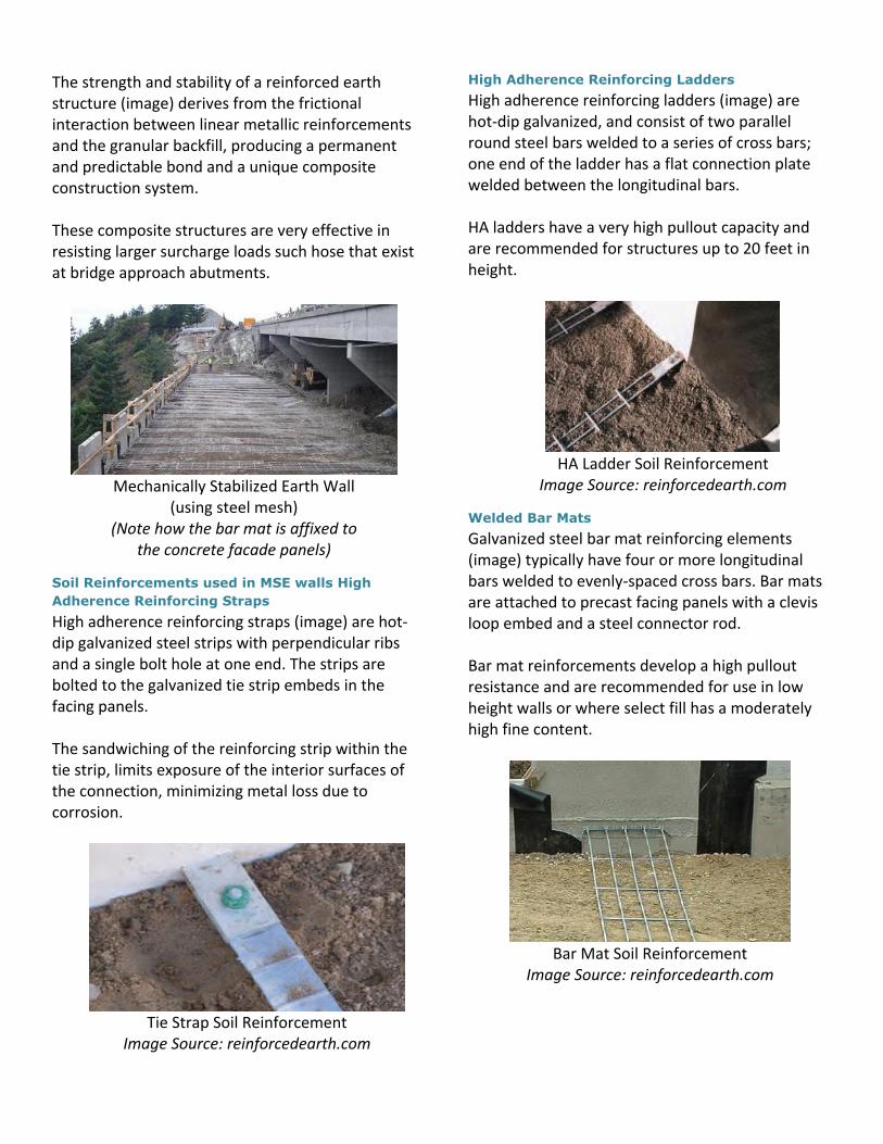
Soil Nailing Systems
Soil nailing (image), is a technique by which retaining walls are reinforced, by the insertion of slender support elements such as steel reinforcing bars. The bars are typically inserted into drilled holes and grouted into place. They are usually installed without tension at a slight downward inclined position.
Soil Nailing Procedure
Image source: Deep excavation A rigid or flexible facing (such as sprayed concrete), or isolated soil nail heads might be used at the surface.
Soil Nail Systems
Soil Nail systems (image) are advantageous in some situations because of the limited space required for installation and the limited easement area behind the proposed wall or shoring. Soil nails may be finished with shotcrete or other facing reinforcement.
Soil Nailed Slope Support System
(attached to wire meshing) Image Source: phigroup.co.uk
Helical Steel Piling
These (image) consist of a galvanized steel shaft with a series of welded low-pitched circular (helical) steel plates. The piles, which vary in diameter depending on the load requirements, are screwed into the ground with hand-held or machine-mounted hydraulic or electrical auger equipment.

Example of a Helical Screw Pier Wall
Image Source: naavaay.com The advantages of helical screw piles over conventional piling:
Quick installation
Causes no vibration during installation
Does not cause fumes due to heavy equipment exhaust
No excavating or spoil to be removed from site
No concrete or curing time
Highly suited for narrow and tight installations
Flexible and sustainable (can be removed and re-used if necessary, or 100% recycled)
Micropiles
Around the 1990’s, micropiles (image) began to catch on as a creative means to provide lateral (tensile) and bearing (compressive) support to foundations, and retaining structures. Micropiles can be used when there are strata of solid rock interlaying softer material. In such cases, a hole is drilled through all the layers using high-pressure hydraulics and pneumatics. Once drilled, a reinforcing member is inserted, similar to rebar, into the hole and then a cement grout is injected from the bottom up. The grout penetrates the softer soils, bonds to the harder ones and creates a friction "grip", able to bear large loads.
Micropile Characteristics
Base on AASHTO and FHWA definitions, micropiles are technically defined as piles which have the following characteristics:
Small diameter (less than 1 ft. in diameter)
Are drilled and grouted into place
Are replacement (not displacement) piles; meaning that the pile is installed by removal and replacement of material as opposed to displacement of existing material. A “displacement” pile is one that installed by displacing existing material. (A driven pile is an example of a “displacement” pile.)
Incorporate steel pipe casing and/or central steel core reinforcement
Reinforced; majority of load resisted by steel casing and/or central steel core reinforcement pile
Diagram of a micropile used for bearing support
Mechanically Stabilized and Reinforced Earth
Systems
Mechanically stabilized earth, or MSE, is soil constructed using artificial reinforcing by way of layered soil anchors fixed at their ends. These mats provide additional internal shear resistance much greater than that of simple gravity wall structures. Other options include layered steel straps. This type of soil strengthening usually requires an outer facade wall upon which to affix the layers.
The strength and stability of a reinforced earth structure (image) derives from the frictional interaction between linear metallic reinforcements and the granular backfill, producing a permanent and predictable bond and a unique composite construction system. These composite structures are very effective in resisting larger surcharge loads such hose that exist at bridge approach abutments.
Mechanically Stabilized Earth Wall
(using steel mesh) (Note how the bar mat is affixed to
the concrete facade panels)
Soil Reinforcements used in MSE walls High
Adherence Reinforcing Straps
High adherence reinforcing straps (image) are hot-dip galvanized steel strips with perpendicular ribs and a single bolt hole at one end. The strips are bolted to the galvanized tie strip embeds in the facing panels. The sandwiching of the reinforcing strip within the tie strip, limits exposure of the interior surfaces of the connection, minimizing metal loss due to corrosion.
Tie Strap Soil Reinforcement
Image Source: reinforcedearth.com
High Adherence Reinforcing Ladders
High adherence reinforcing ladders (image) are hot-dip galvanized, and consist of two parallel round steel bars welded to a series of cross bars; one end of the ladder has a flat connection plate welded between the longitudinal bars. HA ladders have a very high pullout capacity and are recommended for structures up to 20 feet in height.
HA Ladder Soil Reinforcement
Image Source: reinforcedearth.com
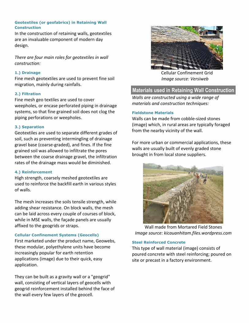
Welded Bar Mats
Galvanized steel bar mat reinforcing elements (image) typically have four or more longitudinal bars welded to evenly-spaced cross bars. Bar mats are attached to precast facing panels with a clevis loop embed and a steel connector rod. Bar mat reinforcements develop a high pullout resistance and are recommended for use in low height walls or where select fill has a moderately high fine content.
Bar Mat Soil Reinforcement
Image Source: reinforcedearth.com
Geotextiles (or geofabrics) in Retaining Wall
Construction
In the construction of retaining walls, geotextiles are an invaluable component of modern day design. There are four main roles for geotextiles in wall construction:
1.) Drainage
Fine mesh geotextiles are used to prevent fine soil migration, mainly during rainfalls.
2.) Filtration
Fine mesh geo textiles are used to cover weepholes, or encase perforated piping in drainage systems, so that fine grained soil does not clog the piping perforations or weepholes.
3.) Separation
Geotextiles are used to separate different grades of soil, such as preventing intermingling of drainage gravel base (coarse-graded), and fines. If the fine grained soil was allowed to infiltrate the pores between the coarse drainage gravel, the infiltration rates of the drainage mass would be diminished.
4.) Reinforcement
High strength, coarsely meshed geotextiles are used to reinforce the backfill earth in various styles of walls. The mesh increases the soils tensile strength, while adding shear resistance. On block walls, the mesh can be laid across every couple of courses of block, while in MSE walls, the façade panels are usually affixed to the geogrids or straps.
Cellular Confinement Systems (Geocells)
First marketed under the product name, Geowebs, these modular, polyethylene units have become increasingly popular for earth retention applications (image) due to their quick, easy application. They can be built as a gravity wall or a "geogrid" wall, consisting of vertical layers of geocells with geogrid reinforcement installed behind the face of the wall every few layers of the geocell.
Cellular Confinement Grid
Image source: Versiweb
Materials used in Retaining Wall Construction
Walls are constructed using a wide range of materials and construction techniques:
Fieldstone Materials
Walls can be made from cobble-sized stones (image) which, in rural areas are typically foraged from the nearby vicinity of the wall. For more urban or commercial applications, these walls are usually built of evenly graded stone brought in from local stone suppliers.
Wall made from Mortared Field Stones
Image source: kicauanhitam.files.wordpress.com
Steel Reinforced Concrete
This type of wall material (image) consists of poured concrete with steel reinforcing; poured on site or precast in a factory environment.

Steel Reinforced Concrete Wall
Gabion Wall System
This type of wall material (image) consists of wire mesh "boxes" or containers, which are filled with roughly cut stone, fractured concrete, or other coarse graded material. Gabion walls are freely draining retaining structures, and because of this, are often built in locations where ground water is an issue.
Gabion Wall along a Roadside Stream
Image source: ca.brockwhite.com
Steel Pilings
Vertical steel pilings (image) are usually used in a wall in conjunction with some type of horizontal laggings. Laggings may be made of treated wood beams, or vinyl, composites, and fiberglass material.
Timber Laggings
This wall material typically consists of treated wooden laggings slide in between the webs of H-shaped steel pilings (soldiers) (image).
Steel Pilings used with Wood Beams
Image source: blog.buildllc.com
Quarried Boulders
These types of materials (image) create a gravity wall of a different sort. Requiring the use of heavy lifting machinery, to move into place, they give the slope a rustic look which blends in with the surroundings of more primitive settings. However, this is considered more of a slope stabilization method than earth retention.
Quarried Boulders in a Rustic Setting
Image source: specialadditionslandscaping.com
Timber Pilings
Timber pilings (image) are usually in the form of 4x4 or 6x6 treated posts. Treated circular fence posts are a good alternative as well. With this type of vertical member, the lagging is placed behind the post.

Timber Pilings
Image Source: greenmanlandscaping.co.nz
Crib Components
This type of wall is one of the oldest and most proven styles of retaining wall design. This wall is designed much like the childhood building block toys, “Lincoln Logs”.
Crib Wall
The façade is made up of horizontal slats or beams, interlaced with notched tieback beams which are many times linked to deadman beams. Due to the large gaps between facial slats, the fill is extra coarsely graded with geotextile fabric behind the fill to prevent fine soil from migrating, thus eroding the slope.
Crib walls (image) consist of:
Timber - horizontal slats or beams of wood installed horizontally to retain rock fill. Creosote impregnated railroad ties are a common building block for these types of walls, however “ground contact” treated 4x4’s or 6x6’s are much more suitable and aesthetically pleasing.
Concrete – precast cellular-style concrete wall sections
Other Non- biodegradable Materials – other assorted materials could be used as well, such as subgrade approved plastics.
Timber and Concrete Crib Walls
Images sources: archiexpo.com and retainingsolutions.com.au
Fiberglass and Composite Pilings
These types of pilings (image) are relatively new to the retaining wall scene, but offer the promise of extended life expectancy, designed to replace the use of timber, steel, and concrete. These wall materials are recommended for waterfront applications where environmental considerations require a sheet pile wall structure that will not rot, decay, rust or spall.
Vinyl Sheet Piling Wall
Interlocking Masonry Blocks
These prefabricated blocks (image) have a locking flange — which makes installation easy for do it yourselfers. They remain in place by either self-weight, or with the use of mortar or adhesives.
Interlocking Blocks
Batter Walls and Tiered Walls
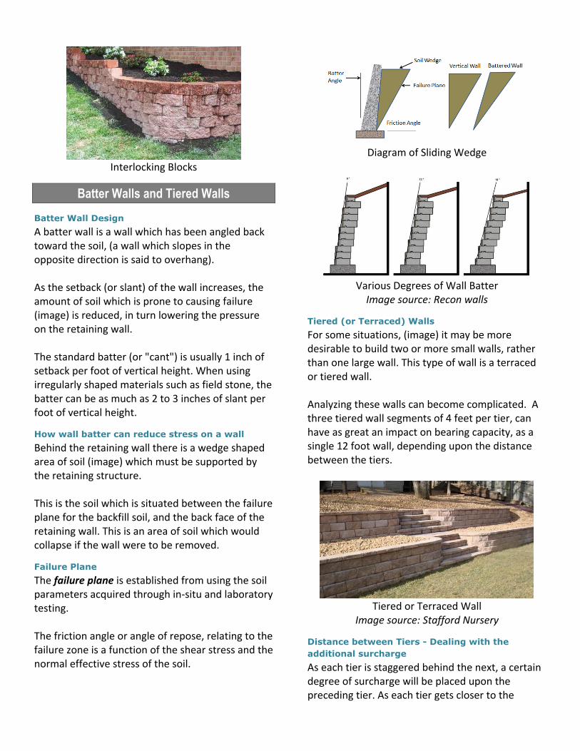
Batter Wall Design
A batter wall is a wall which has been angled back toward the soil, (a wall which slopes in the opposite direction is said to overhang). As the setback (or slant) of the wall increases, the amount of soil which is prone to causing failure (image) is reduced, in turn lowering the pressure on the retaining wall. The standard batter (or "cant") is usually 1 inch of setback per foot of vertical height. When using irregularly shaped materials such as field stone, the batter can be as much as 2 to 3 inches of slant per foot of vertical height.
How wall batter can reduce stress on a wall
Behind the retaining wall there is a wedge shaped area of soil (image) which must be supported by the retaining structure. This is the soil which is situated between the failure plane for the backfill soil, and the back face of the retaining wall. This is an area of soil which would collapse if the wall were to be removed.
Failure Plane
The failure plane is established from using the soil parameters acquired through in-situ and laboratory testing. The friction angle or angle of repose, relating to the failure zone is a function of the shear stress and the normal effective stress of the soil.
Diagram of Sliding Wedge
Various Degrees of Wall Batter
Image source: Recon walls
Tiered (or Terraced) Walls
For some situations, (image) it may be more desirable to build two or more small walls, rather than one large wall. This type of wall is a terraced or tiered wall. Analyzing these walls can become complicated. A three tiered wall segments of 4 feet per tier, can have as great an impact on bearing capacity, as a single 12 foot wall, depending upon the distance between the tiers.
Tiered or Terraced Wall
Image source: Stafford Nursery
Distance between Tiers - Dealing with the
additional surcharge
As each tier is staggered behind the next, a certain degree of surcharge will be placed upon the preceding tier. As each tier gets closer to the

adjacent lower tier, the surcharge loading on the lower section is increased. When a tier is placed within the failure plane of that lower adjacent tier, the surcharge will need to be included in the total “tally” of lateral forces which the lower tiered section may be subjected to.
Tier Spacing 2X the Height
A good rule of thumb to use, to avoid adding surcharge to a lower tier, is to double the height of the lower tier, and use that as the spacing measurement between tiered sections (image). For example, if Tier 1 (the bottom tier) is 5 feet high, then Tier 2 should be spaced horizontally 10 feet from that tier, in order to safely eliminate a surcharge load.
Tier Spacing between Wall Sections Image Source: retaining wall expert
Proportioning - Using Proper Wall Proportions
Proportioning
In retaining wall design, engineers must make certain assumptions concerning some of the dimensions of the wall, called “proportioning”, in order to arrive at a rough idea of the wall’s preliminary measurements. Arriving at the proper proportions, when planning a retaining wall is a key part of the iterative design process. Some proportional assumptions to consider:
Top of the stem
of any cast concrete retaining wall should be no less than 10 to 12 inches to account for the proper placement of concrete. Overall wall dimensions are also affected by the required minimum reinforcement coverage. This can add several inches to the wall's thickness, and can vary dependent on: severity of exposure, soil type, and reactivity.
Depth to the bottom of the base slab
This should be kept at a minimum of 20 to 24 inches. Note: it should always be located at a depth below the seasonal frost line.
Length of the base slab
This is usually about 50% to 70% of the total height of the wall (bottom of base to top of stem).
Stem thickness at the base (for cantilever and
counterfort walls)
This is often about 10% of the total wall height.
Base slab thickness
This is often about 10% of the total wall height as well.
Counterforts spacing
The spacing for center to center distances is roughly 30% to 70% of the total wall height. Note: For counterfort retaining walls, the general proportion of the stem and the base slab is the same as for cantilever walls.
Components of a Wall (image)
Base - Footing or foundation of the wall Stem - The vertical portion of the wall which resists the lateral earth pressures Key - The notched portion of the base, which resists sliding of the wall Toe - The point about which overturning moments rotate Weephole - Drainage hole to relieve hydrostatic pressure behind the wall Counterfort (not shown) - The webbed portion used to add support and extra resisting weight
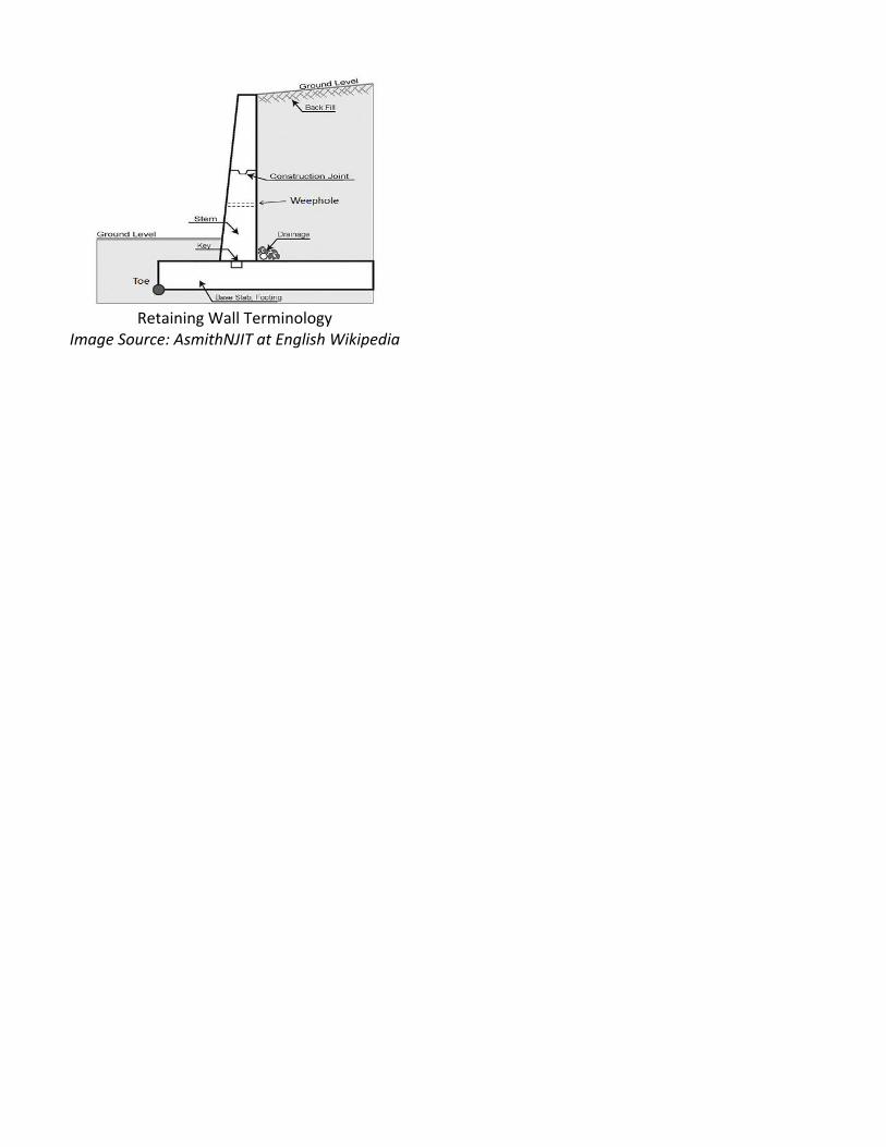
Retaining Wall Terminology
Image Source: AsmithNJIT at English Wikipedia

Chapter Two: Forces on a
Retaining Wall
Wall Stabilization
Having a Stabilized Wall
Walls need to be stabilized in order to remain at an equalized state, against sliding, pivoting, sinking, and rolling out of their supportive position. To have a “stabilized wall”, the forces which are seeking to cause the failure of the wall, must be less than the resisting forces seeking to prevent the failure. To verify the stability of a retaining wall, these steps are followed:
Check for overturning about the toe
Check for sliding failure along the base
Check for bearing capacity failure at the base
Check for settlement at the base
Check the overall stability (wall and surrounding soil mass
Internal vs. External Stability
Internal Stability vs External Stability
The means in which a wall is stabilized are:
1.) Externally Stabilized
Walls which are supported and stabilized by means outside the wall, or within the structure of the wall include:
Gravity type structures (gravitational weight)
Semi-gravity type structures (gravitational weight and steel reinforcing)
Cantilever type structures (gravitational weight and steel reinforcing)
Counterfort type structures (gravitational weight, steel reinforcing, and internal struts or buttresses)
Buttress walls (gravitational weight, steel reinforcing, and exterior struts or buttresses)
Prefabricated interlocking masonry blocks (gravitational weight and wall batter)
2.) Internally Stabilized
Walls which are supported and stabilized by means inside the backfill soil mass, the in-situ (existing undisturbed ground) soil mass, include:
Bored piling walls (grouted pilings and soil friction)
Micro-piles (grouted micro-pilings and soil friction)
Soil nailing systems (grouted members and soil friction)
Reinforced Earth systems (compacted-in-place strips, fabrics, meshes, grids, and backfill soil friction)
Stabilizing structural members which are drilled and grouted into the bedrock would also be considered internally stabilized.
Forces on a Retaining Wall
Wall Movement
The two groups of forces that act on a retaining wall:
Those that tend to cause the wall to move (Destabilizing)
Those forces which oppose movement of the wall (Stabilizing)
Group One (Cause Movement)
the weight of the soil behind the retaining wall (image)
surcharges on the backfill such as: slabs, roads, buildings, stockpiles, and other vertical loads applied to the backfill
Hydrostatic pressure from undrained water
Seismic vibration or construction related vibration (earthquake, blasting, pile driving, etc.)
Group Two (Oppose Movement)
The weight of the wall structure
the frictional resistance to sliding due to the weight of the wall
the passive resistance of the soil in front of the wall (image)
the force provided by mechanical restraining devices such as tiebacks, anchors, geotextiles

Types of Wall Movements
The wall can move in various ways such as:
Wall slides outward away from the backfill (Sliding)
Wall pivots about a moment center located at the lower front face of the base (Overturning)
Wall sinks in the front under the toe, and can simultaneously rotate outward (Bearing Capacity)
Wall and nearby soil mass slide and rotate due to a larger circular shear plane (Shallow and Deep Shear)
The Three Cases of Lateral Earth Pressures
Lateral Earth Pressure
This is the pressure that soil exerts horizontally. This is an important concept to understand, as it affects the consolidating behavior and strength of the soil. There are three cases of lateral earth pressure on a wall: at-rest, passive, and active. The three cases of lateral earth pressure are:
Case 1: At-Rest Condition of Lateral Earth
Pressure
With this category of lateral earth pressure there is no lateral movement of the wall, either away from or toward the backfill soil (image), thus the wall is in a state of static equilibrium. This condition usually occurs when the wall is restrained at the top and bottom against free movement. (An example would be a full depth or partial depth basement wall. This wall would be fully restrained from moving by the first floor anchoring, and the basement’s concrete slab.)
At Rest Case of Lateral Earth Pressure This would be the equation for an at-rest case when the backfill soil is coarse grained backfill:
Case 2: Active Condition of Lateral Earth
Pressure
With this category of lateral earth pressure there is movement of the wall away from the backfill soil (image). This is the typical scenario of a standard retaining wall, which experiences outward movement due to the pressures which come from the backfilled soil mass, surcharge loading, and hydrostatic pressures. This condition allows the soil mass within the failure zone free movement, with the potential for sliding, overturning, and global instability failures.

Active Case of Lateral Earth Pressure
Case 3: Passive Case of Lateral Earth Pressure
With this category of lateral earth pressure, movement of the wall is toward the backfill soil (image). This condition develops in the soil in front of the wall (around the wall’s face), and below grade. When the wall moves inward, it experiences the full passive pressure.
Passive Case of Lateral Earth Pressure
Lateral Earth Coefficients
Use of Coefficients
To find the horizontally acting component of a vertical resultant vector force (such as overburden and surcharge pressures), we make use of dimensionless coefficients. (These can be derived by algebraic or trigonometric relationships). There’s not one particular coefficient equation which applies to all soil conditions. Depending upon whether the soil is loose or dense sand, normally consolidated clay, or over consolidated clay, there are various equations used, that depend upon the soil’s individual properties when calculating the lateral earth pressure coefficient. The coefficient of lateral earth pressure, K, is defined as the ratio of the horizontal effective stress, (Ơh’), to the vertical effective stress, (Ơv‘). The effective stress is the intergranular stress calculated by subtracting the pore pressure from the total stress. The vertical effective stress at a depth (z) is simply the unit weight of the soil times the depth. The horizontal effective stress is the vertical effective stress times the coefficient (K). Given a mass of soil, restrained by a frictionless wall of height H. A soil element located at a depth z is subjected to a vertical effective pressure (Ơv ‘) and a horizontal effective pressure (Ơh’). Assume that there are no shear stresses on the vertical and horizontal planes of the soil element.
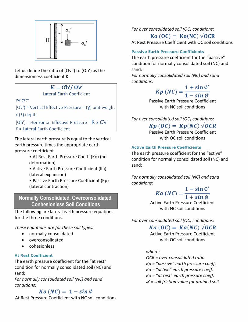
Let us define the ratio of (Ơv ‘) to (Ơh’) as the dimensionless coefficient K:
The lateral earth pressure is equal to the vertical earth pressure times the appropriate earth pressure coefficient.
• At Rest Earth Pressure Coeff. (Ko) (no deformation) • Active Earth Pressure Coefficient (Ka) (lateral expansion) • Passive Earth Pressure Coefficient (Kp) (lateral contraction)
Normally Consolidated, Overconsolidated, Conhesionless Soil Conditions
The following are lateral earth pressure equations for the three conditions.
These equations are for these soil types:
normally consolidated
overconsolidated
cohesionless
At Rest Coefficient
The earth pressure coefficient for the “at rest” condition for normally consolidated soil (NC) and sand: For normally consolidated soil (NC) and sand conditions:
𝑲𝒐 (𝑵𝑪) = 𝟏 − 𝒔𝒊𝒏 ∅ At Rest Pressure Coefficient with NC soil conditions
For over consolidated soil (OC) conditions:
𝐊𝐨 (𝐎𝐂) = 𝐊𝐨(𝐍𝐂) √𝐎𝐂𝐑 At Rest Pressure Coefficient with OC soil conditions
Passive Earth Pressure Coefficients
The earth pressure coefficient for the “passive” condition for normally consolidated soil (NC) and sand: For normally consolidated soil (NC) and sand conditions:
𝑲𝒑 (𝑵𝑪) =𝟏 + 𝐬𝐢𝐧 ∅′
𝟏 − 𝒔𝒊𝒏 ∅′
Passive Earth Pressure Coefficient with NC soil conditions
For over consolidated soil (OC) conditions:
𝑲𝒑 (𝑶𝑪) = 𝑲𝒑(𝑵𝑪) √𝑶𝑪𝑹 Passive Earth Pressure Coefficient
with OC soil conditions
Active Earth Pressure Coefficients
The earth pressure coefficient for the “active” condition for normally consolidated soil (NC) and sand: For normally consolidated soil (NC) and sand conditions:
𝑲𝒂 (𝑵𝑪) =𝟏 − 𝐬𝐢𝐧 ∅′
𝟏 + 𝒔𝒊𝒏 ∅′
Active Earth Pressure Coefficient with NC soil conditions
For over consolidated soil (OC) conditions:
𝑲𝒂 (𝑶𝑪) = 𝑲𝒂(𝑵𝑪) √𝑶𝑪𝑹 Active Earth Pressure Coefficient
with OC soil conditions
where: OCR = over consolidated ratio Kp = “passive” earth pressure coeff. Ka = “active” earth pressure coeff. Ko = “at rest” earth pressure coeff.
’ = soil friction value for drained soil
Finding Lateral Earth Pressure Coefficients
Using Empirical Data (Tables) to find Lateral
Earth Pressure Coefficients
Tables can be found in a wide variety of geotechnical publications, which give all 3 coefficients based on various forms of the coefficient formula, which might include a mixture of soil parameters such as: cohesion, friction angle, backfill surface angle, unit weight of the soil, among many others.
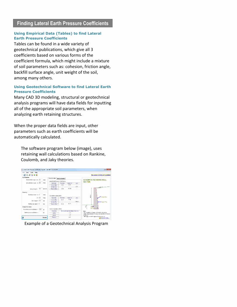
Using Geotechnical Software to find Lateral Earth
Pressure Coefficients
Many CAD 3D modeling, structural or geotechnical analysis programs will have data fields for inputting all of the appropriate soil parameters, when analyzing earth retaining structures. When the proper data fields are input, other parameters such as earth coefficients will be automatically calculated.
The software program below (image), uses retaining wall calculations based on Rankine, Coulomb, and Jaky theories.
Example of a Geotechnical Analysis Program
Hydrostatic Pressure on a Wall
Drainage of Retaining Wall Backfill
One design aspect that should not be overlooked, or underestimated, is the need to quickly drain the backfill of stormwater. Hydrostatic pressures behind a wall can nearly double the applied pressure on the wall if it isn’t properly accounted for in the calculations and design. Rapid water build up behind retaining structures is one of the principle causes of retaining wall failures. Drainage of water, resulting from rainfall or other wet conditions is very important to the stability of a retaining wall. Without proper drainage, the backfill can become saturated, which has the dual hazards of increasing the pressure on the wall, plus lessening the resistance of the backfill material to sliding. To increase infiltration rates of the backfill, and speed up the draining of stormwater, use of a granular backfill material is recommended. Benefits are good drainage, easy compaction, and an increased soil friction angle over cohesive soil types.
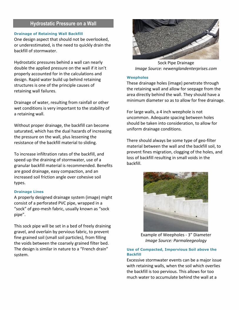
Drainage Lines
A properly designed drainage system (image) might consist of a perforated PVC pipe, wrapped in a “sock” of geo-mesh fabric, usually known as “sock pipe”. This sock pipe will be set in a bed of freely draining gravel, and overlain by pervious fabric, to prevent fine grained soil (small soil particles), from filling the voids between the coarsely grained filter bed. The design is similar in nature to a “French drain” system.
Sock Pipe Drainage
Image Source: newenglandenterprises.com
Weepholes
These drainage holes (image) penetrate through the retaining wall and allow for seepage from the area directly behind the wall. They should have a minimum diameter so as to allow for free drainage. For large walls, a 4 inch weephole is not uncommon. Adequate spacing between holes should be taken into consideration, to allow for uniform drainage conditions. There should always be some type of geo-filter material between the wall and the backfill soil, to prevent fines migration, clogging of the holes, and loss of backfill resulting in small voids in the backfill.
Example of Weepholes - 3” Diameter
Image Source: Parmaleegeology
Use of Compacted, Impervious Soil above the
Backfill
Excessive stormwater events can be a major issue with retaining walls, when the soil which overlies the backfill is too pervious. This allows for too much water to accumulate behind the wall at a
rate greater than the drainage system can discharge it. To counteract this, it’s recommended that the backfill should be overlain by a minimal 6” lift of compacted, low permeability soil which sheds the water rather than allowing it to infiltrate behind the wall, causing a rapid water buildup.
Surcharge Loads
Surcharge Loading on a Wall
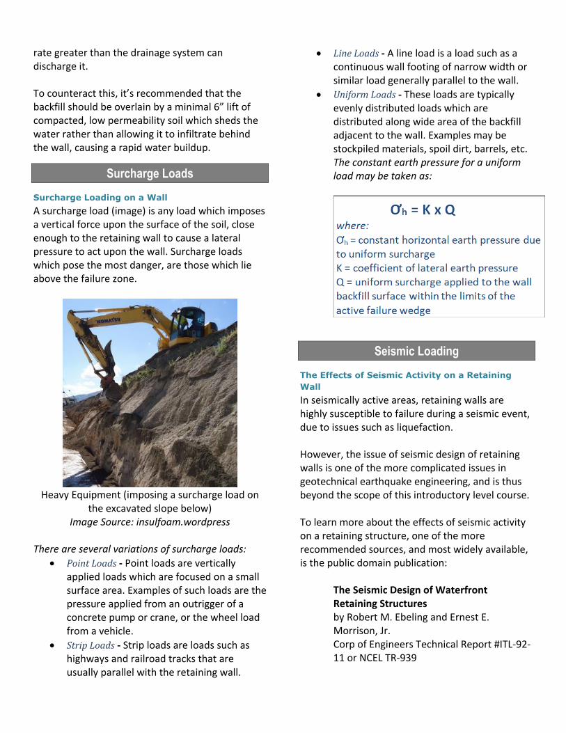
A surcharge load (image) is any load which imposes a vertical force upon the surface of the soil, close enough to the retaining wall to cause a lateral pressure to act upon the wall. Surcharge loads which pose the most danger, are those which lie above the failure zone.
Heavy Equipment (imposing a surcharge load on
the excavated slope below) Image Source: insulfoam.wordpress
There are several variations of surcharge loads:
Point Loads - Point loads are vertically applied loads which are focused on a small surface area. Examples of such loads are the pressure applied from an outrigger of a concrete pump or crane, or the wheel load from a vehicle.
Strip Loads - Strip loads are loads such as highways and railroad tracks that are usually parallel with the retaining wall.
Line Loads - A line load is a load such as a continuous wall footing of narrow width or similar load generally parallel to the wall.
Uniform Loads - These loads are typically evenly distributed loads which are distributed along wide area of the backfill adjacent to the wall. Examples may be stockpiled materials, spoil dirt, barrels, etc. The constant earth pressure for a uniform load may be taken as:
Seismic Loading
The Effects of Seismic Activity on a Retaining
Wall
In seismically active areas, retaining walls are highly susceptible to failure during a seismic event, due to issues such as liquefaction. However, the issue of seismic design of retaining walls is one of the more complicated issues in geotechnical earthquake engineering, and is thus beyond the scope of this introductory level course. To learn more about the effects of seismic activity on a retaining structure, one of the more recommended sources, and most widely available, is the public domain publication:
The Seismic Design of Waterfront Retaining Structures by Robert M. Ebeling and Ernest E. Morrison, Jr. Corp of Engineers Technical Report #ITL-92-11 or NCEL TR-939
Chapter 3: Backfill Soil
Conditions
Backfill Soil
Using Acceptable Backfill Soils
One of the most important factors to consider, when designing a retaining wall, is the type of soil used in the backfill. The ideal backfill of choice will be a free-draining, granular soil with high shear strength properties. In order to create a stable earth retention structure, the existing soil (native soil) behind the wall will likely need to be removed and a more suitable soil type brought in from offsite which has been properly graded specifically for use as retaining wall backfill. There are times when native cohesive soil must be used as backfill due to the inaccessibility of the site, or unavailability of properly graded fill within a reasonable distance of haul. When use of the correct fill is not feasible, then it is prudent to design the structure solid enough to withstand the hazards posed, of those unpredictable native soil conditions especially during and after rain events (swell and contraction, consolidation, desiccation, substandard shear strength, liquefaction potential, etc.).
To use Non-Cohesive Soils (Sandy Soil) or
Cohesive Soils (Clayey Soil)
The preferred soil for backfill behind retaining walls is soil that contains a high percentage of sand and gravel. Such a soil is referred to as a granular soil and has a friction angle of approximately 32° to 36°, depending on the degree of compaction of the soil. The main reason for preferring a granular soil for backfill is that it allows water to pass through it more easily than a non-granular, or clayey soil does. Also, the shear strength of a granular soil does not vary with the moisture content; therefore its shear strength is more predictable, and thus easier to design for.
Cohesive Soil - Poor Choice as a Backfill Soil
Clay soil varieties have characteristics that make it less than suitable for use as backfill for a retaining wall. First of all, clay soil is not sufficiently permeable and tends to retain the water that seeps into it. This added weight of the retained water increases the forces on the retaining wall. Second, once the clay becomes saturated, its cohesion decreases to nearly zero (turning to “mud”, as in mudslides). The shear strength of a soil is the sum of the frictional resistance to movement and the cohesion of the soil. Once the cohesion is lost due to soil saturation, the full force of the weight of water and most of the weight of the soil is applied to the wall. For these reasons, clay soil is not recommended as a suitable choice for retaining wall backfill.
Use of Rock as Backfill
Rock is a desirable choice for use as a backfill for retaining walls, and should be given due consideration whenever available. The rock fill should be consistently graded. A well-graded, densely compacted rock fill should consist of no more than roughly 2% fine grained soils, if it is to remain free draining. Rock fill Is a key component in gabion-style and crib-style walls.
Classifying of Soils
Acceptable Soil Classes
Certain fine grained cohesive soils may be used in wall construction, but additional backfilling, compaction and water management efforts are required. The following soil types should not be used in wall construction:
Poorly graded sands
Expansive clays
Soils with a plasticity index (PI) >20
Soils with a liquid limit (LL) >40 While cohesion-less free draining materials are preferred, with the following properties:
Less than 10% fines, and/or
Plasticity index less than 6
Liquid limit less than 30 These soils may be used for construction under certain conditions:
Low plasticity fines
(ie: CL, ML. SM, SC)
PI less than 20
LL less than 40) However, the ultimate choice of backfill soil should be based on the cost and availability of such ideal materials, weighed against the cost of a more expensively constructed and designed wall. If cohesive soil is your only option as a backfill, the wall will need to designed and built accordingly, in order to give the client a well-built, well-functioning structure.
Atterberg Limits
The Atterberg Limits are used as a basic measure of the critical water contents of a fine-grained soil. These measures include its shrinkage limit, plastic limit, and liquid limit. As dry, clayey soil takes on water, it undergoes a dramatic and distinct change in its behavior and consistency. Depending on the soil’s water content, it may appear in four states: solid, semi-solid, plastic and liquid. In each state, the consistency and behavior of a soil differs as do its engineering properties. Thus, the transition between each state can be defined based on the change of soil behavior.
Shrinkage Limit (SL)
The shrinkage limit (SL) is the water content where further loss of moisture will not result in any more volume reduction. The shrinkage limit is less commonly used than the liquid and plastic limits.
Plastic Limit (PL)
The plastic limit (PL) is determined by rolling out a thread of a fine portion of the soil onto a flat, non-porous surface. If the soil is at a moisture content where it behaves as a plastic, the thread will retain its shape down to
a narrow diameter. The sample can then be remolded and the test repeated. As the moisture content falls due to evaporation, the thread will begin to break apart at larger diameters. The plastic limit is defined as the moisture content where the thread breaks apart at a diameter of 3.2 mm (about 1/8 inch). A soil is considered non-plastic if a thread cannot be rolled out down to 3.2 mm at any moisture.
Liquid Limit (LL)
The liquid limit (LL) is defined, in concept as the water content at which the behavior of a clayey soil changes from a plastic to a liquid. The transition from plastic to liquid behavior is gradual over a range of water contents, and the shear strength of the soil is not actually zero at the liquid limit.
Plasticity Index (PI)
The plasticity index (PI) is a measure of the plasticity of a soil. The plasticity index is the range of water contents where the soil exhibits plastic properties. The PI is the difference between the liquid limit and the plastic limit (PI = LL-PL). Soils with a high PI tend to be clayey, while those with a lower PI tend to be silty, and those with a PI of 0 (non-plastic) tend to have little to no silt or clay content.
PI Ranges:
(0-3)- Nonplastic
(3-15) - Slightly plastic
(15-30) - Medium plastic
>30 - Highly plastic
Unified Soil Classifications
The Unified Soil Classification System (USCS) is a soil classification system used to describe the texture and grain size of a soil type. This classification system can be applied to most unconsolidated materials, and is represented by a two-letter symbol.

Unified Soil Classification System (USCS)
Group Symbols
Soil Compaction
Soil Compaction for Fill Soils
Soil compaction is the process of rearranging recently laid soil particles to consolidate the space occupied by those particles, while expelling the excess air and water within the voids. Compaction is accomplished by applying a vibratory force to layers of deposited soil called “lifts”. Successful compaction will be dependent upon the soil type being worked, the moisture content of the soil, and the compaction technique being used. A properly compacted soil helps to strengthen the internal strength of the soil mass by realigning the soil particles, and increasing the coefficient of friction (improving shear strength), as well as reducing undesirable settlement.
Degree of Compaction - Relative Density
In granular soils, the degree of compaction in the field can be measured according to the relative density, (Dr). When the value of Dr = 100%, the soil is very dense, and when Dr = 0% the soil is extremely loose and unstable soil conditions exist.
Dr = (emax – e) / (emax – emin) x 100% Relative Density of Granular Soil
where:
emax is the "maximum void ratio" corresponding to a very loose state
emin is the "minimum void ratio" corresponding to a very dense state
e is the in situ (undisturbed soil) void ratio
Soil Compaction Testing
The industry standard method of testing soil compaction is the (SPT) Standard Proctor Test (covered in the next page). The level of compaction in a soil mass is determined by comparing the density of the soil (as measured at the site) to the density of that soil type (as defined by the Standard Proctor tests). For example, if specifications require compaction to be “95 percent of the Standard Proctor”, this means the onsite soil density must equal 95% of the “maximum achievable” compaction.
Soil Compaction Methods
Compaction may be achieved by applying three basic types of force to the backfill soil.
Vibration Method
Soil vibratory machines send waves through the soil to reposition and consolidate the soil particles. This type of force does a good job at forcing out excess air within the uncompacted mass. Vibratory machines work well in noncohesive soils (soils comprised of a minimal 50 percent sand or gravel).
Vibratory Plate Soil Compactor
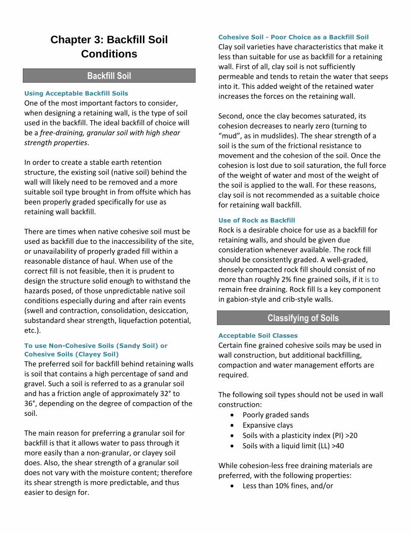
Ramming Method
Soil rammers such as a tamping rammer or vibrating sheep foot rollers, simulate the action of striking the ground with a hammer. This type of force is productive with highly cohesive clay soils because it breaks down the soil masses and expunges excess moisture.
Vibratory Tamping Rammer
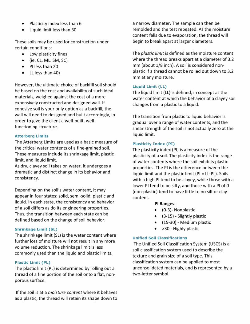
Vibratory Rollers
These units work similar to the non-vibratory roller equipment, with the exception of the obviously having a vibrating soil compacting roller. Most of these units have a water tank which can be filled or emptied to adjust the weight applied to the soil. Additionally, they usually have sprayers which can dampen the soil during each pass.
Vibratory Walk behind Roller
Static (non-vibratory) Method
This method utilizes the weight of the roller compaction machinery without the benefit of vibratory motion. Usually this will only yield
compaction of a thin top layer of soil where the load is applied. A heavy, “walk behind” roller can develop suitable results when used on an 8 to 10 inch lift. This method obtains proper compaction using broad area machinery surfaces such as with a weighted roller, but yields poor results when used with more focused loads such as by driving construction equipment back and forth over the soil. Heavy equipment should never be driven within 3 feet of the back face of the wall, or near the “sliding soil wedge” area of the backfill.
Adding water during the compaction process
The compaction process is aided by controlling the amount of moisture within the soil. Proper amounts of water act as a particle lubricant to help consolidate the soil particles as they are being compacted. When there is too much water in the soil, the water occupies space within the voids between the soil particles, preventing them from meshing together. If the soil is too dry, water will be required as each new lift of soil will require the lubrication in order to properly adjust and realign.
Soil Consolidation
The Consolidation Process of Soil
Sometimes soil consolidation can be confused with soil compaction (the mechanical packing of soil). Basically, consolidation is the process in which a reduction in volume takes place by expulsion of water under long term static overburden loading. It occurs when stress is applied to a soil causing the soil particles to realign and pack together more tightly, therefore reducing its bulk volume. When this occurs in a soil that is saturated with water, water will be squeezed out of the pores or voids in the soil.
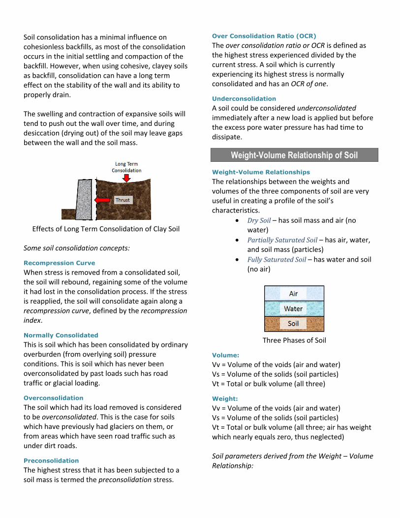
Soil consolidation has a minimal influence on cohesionless backfills, as most of the consolidation occurs in the initial settling and compaction of the backfill. However, when using cohesive, clayey soils as backfill, consolidation can have a long term effect on the stability of the wall and its ability to properly drain. The swelling and contraction of expansive soils will tend to push out the wall over time, and during desiccation (drying out) of the soil may leave gaps between the wall and the soil mass.
Effects of Long Term Consolidation of Clay Soil
Some soil consolidation concepts:
Recompression Curve
When stress is removed from a consolidated soil, the soil will rebound, regaining some of the volume it had lost in the consolidation process. If the stress is reapplied, the soil will consolidate again along a recompression curve, defined by the recompression index.
Normally Consolidated
This is soil which has been consolidated by ordinary overburden (from overlying soil) pressure conditions. This is soil which has never been overconsolidated by past loads such has road traffic or glacial loading.
Overconsolidation
The soil which had its load removed is considered to be overconsolidated. This is the case for soils which have previously had glaciers on them, or from areas which have seen road traffic such as under dirt roads.
Preconsolidation
The highest stress that it has been subjected to a soil mass is termed the preconsolidation stress.
Over Consolidation Ratio (OCR)
The over consolidation ratio or OCR is defined as the highest stress experienced divided by the current stress. A soil which is currently experiencing its highest stress is normally consolidated and has an OCR of one.
Underconsolidation
A soil could be considered underconsolidated immediately after a new load is applied but before the excess pore water pressure has had time to dissipate.
Weight-Volume Relationship of Soil
Weight-Volume Relationships
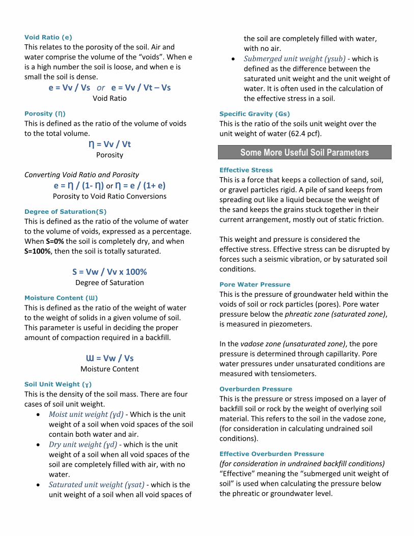
The relationships between the weights and volumes of the three components of soil are very useful in creating a profile of the soil’s characteristics.
Dry Soil – has soil mass and air (no water)
Partially Saturated Soil – has air, water, and soil mass (particles)
Fully Saturated Soil – has water and soil (no air)
Three Phases of Soil
Volume:
Vv = Volume of the voids (air and water) Vs = Volume of the solids (soil particles) Vt = Total or bulk volume (all three)
Weight:
Vv = Volume of the voids (air and water) Vs = Volume of the solids (soil particles) Vt = Total or bulk volume (all three; air has weight which nearly equals zero, thus neglected) Soil parameters derived from the Weight – Volume Relationship:
Void Ratio (e)
This relates to the porosity of the soil. Air and water comprise the volume of the “voids”. When e is a high number the soil is loose, and when e is small the soil is dense.
e = Vv / Vs or e = Vv / Vt – Vs Void Ratio
Porosity (Ƞ)
This is defined as the ratio of the volume of voids to the total volume.
Ƞ = Vv / Vt Porosity
Converting Void Ratio and Porosity
e = Ƞ / (1- Ƞ) or Ƞ = e / (1+ e) Porosity to Void Ratio Conversions
Degree of Saturation(S)
This is defined as the ratio of the volume of water to the volume of voids, expressed as a percentage. When S=0% the soil is completely dry, and when S=100%, then the soil is totally saturated.
S = Vw / Vv x 100% Degree of Saturation
Moisture Content (Ɯ)
This is defined as the ratio of the weight of water to the weight of solids in a given volume of soil. This parameter is useful in deciding the proper amount of compaction required in a backfill.
Ɯ = Vw / Vs Moisture Content
Soil Unit Weight (ɣ)
This is the density of the soil mass. There are four cases of soil unit weight.
Moist unit weight (ɣd) - Which is the unit weight of a soil when void spaces of the soil contain both water and air.
Dry unit weight (ɣd) - which is the unit weight of a soil when all void spaces of the soil are completely filled with air, with no water.
Saturated unit weight (ɣsat) - which is the unit weight of a soil when all void spaces of
the soil are completely filled with water, with no air.
Submerged unit weight (ɣsub) - which is defined as the difference between the saturated unit weight and the unit weight of water. It is often used in the calculation of the effective stress in a soil.
Specific Gravity (Gs)
This is the ratio of the soils unit weight over the unit weight of water (62.4 pcf).
Some More Useful Soil Parameters
Effective Stress
This is a force that keeps a collection of sand, soil, or gravel particles rigid. A pile of sand keeps from spreading out like a liquid because the weight of the sand keeps the grains stuck together in their current arrangement, mostly out of static friction. This weight and pressure is considered the effective stress. Effective stress can be disrupted by forces such a seismic vibration, or by saturated soil conditions.
Pore Water Pressure
This is the pressure of groundwater held within the voids of soil or rock particles (pores). Pore water pressure below the phreatic zone (saturated zone), is measured in piezometers. In the vadose zone (unsaturated zone), the pore pressure is determined through capillarity. Pore water pressures under unsaturated conditions are measured with tensiometers.
Overburden Pressure
This is the pressure or stress imposed on a layer of backfill soil or rock by the weight of overlying soil material. This refers to the soil in the vadose zone, (for consideration in calculating undrained soil conditions).
Effective Overburden Pressure
(for consideration in undrained backfill conditions) “Effective” meaning the “submerged unit weight of soil” is used when calculating the pressure below the phreatic or groundwater level.
Example of Overburden Pressure:
Assuming that a soil has a total unit weight (ɣ) of 125 pcf and the groundwater level is 4 feet below the ground surface. The vertical effective overburden pressure (Ơv’) at a depth of 10 feet below the ground surface (i.e. 4 feet below the groundwater depth) is:
Ơv’ = 4(ɣ) + 4(ɣ - ɣ’)
Effective Overburden Pressure Where ɣ is the total unit weight of the soil and ɣ’ is the effective (or submerged) unit weight of the soil, equaling the total unit weight of soil minus the unit weight of water (62.4 pcf). Therefore: Ơv’ = 4(125) + 4(125-62.4) = 750 psf
Soil Cohesion (c)
This refers to the shear strength of the soil, in the absence of compressive stresses.
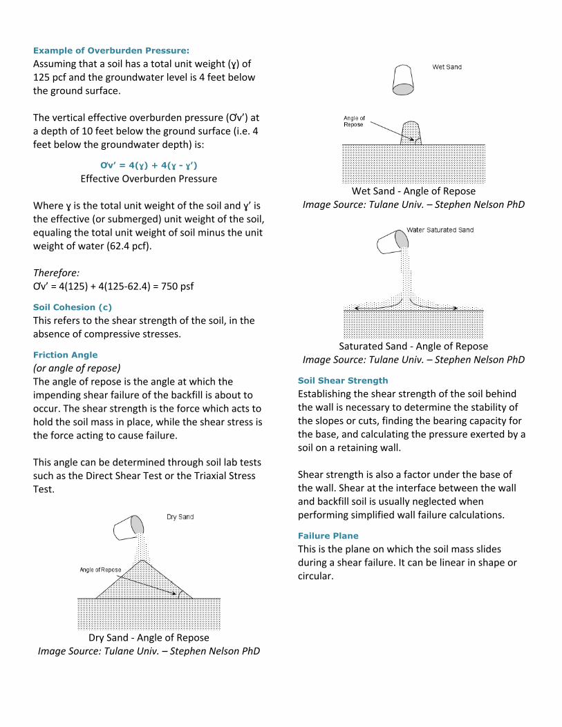
Friction Angle
(or angle of repose) The angle of repose is the angle at which the impending shear failure of the backfill is about to occur. The shear strength is the force which acts to hold the soil mass in place, while the shear stress is the force acting to cause failure. This angle can be determined through soil lab tests such as the Direct Shear Test or the Triaxial Stress Test.
Dry Sand - Angle of Repose
Image Source: Tulane Univ. – Stephen Nelson PhD
Wet Sand - Angle of Repose
Image Source: Tulane Univ. – Stephen Nelson PhD
Saturated Sand - Angle of Repose
Image Source: Tulane Univ. – Stephen Nelson PhD
Soil Shear Strength
Establishing the shear strength of the soil behind the wall is necessary to determine the stability of the slopes or cuts, finding the bearing capacity for the base, and calculating the pressure exerted by a soil on a retaining wall. Shear strength is also a factor under the base of the wall. Shear at the interface between the wall and backfill soil is usually neglected when performing simplified wall failure calculations.
Failure Plane
This is the plane on which the soil mass slides during a shear failure. It can be linear in shape or circular.

Failure Plane
Soil Testing in the Field (In situ)
Vane Shear Test
(In situ or in Ground Test for Clay Soils) When testing for the undrained shear strength of very soft to medium cohesive soils, fairly reliable results may be obtained directly from performing vane shear tests (image). These tests are simple to perform, and can be done very affordably in the field. The shear vane usually consists of four thin, equal-sized steel plates welded to a steel torque rod (image). To perform the simple vane shear test, the vane is pushed into the soil. Torque is applied using a torque wrench at the top of the rod to rotate the vane at a uniform speed. A cylinder of soil of height (ft.) and diameter (d) will resist the torque until the soil fails. The undrained shear strength of the cohesive soil can then be calculated from the torque wrench readings.
Vane Shear Testing Apparatus
Image Source: geoengineer.org
Standard Penetration Test (SPT)
This test uses a thick-walled sample tube that is driven into the ground by blows from a 140 lb. slide
hammer falling a distance of 30 in. The number of blows needed for the tube to penetrate each 6 in. interval is recorded (excluding the first 6 Inches). The sum of the number of blows required for the second and third 6 in. of penetration is termed the "standard penetration resistance" or the "N-value". The purpose of this test is to provide an indication of the relative density of sands and gravels from which it is virtually impossible to obtain undisturbed samples.
Cone Penetration or Cone Penetrometer Test
The CPT is one of the most used and accepted soil testing methods for soil investigation worldwide, being more popular than the SPT for geotechnical soil investigation. It has more accuracy, speed of deployment, more continuous soil profile, and reduced cost over other methods of soil testing. The ability to include other in situ tools using the CPT direct push drilling rig, helps in making this the more popular choice among geotechnical soil testing professionals for in situ testing. The CPT application (image) was standardized in 1986 by the ASTM, Standard number D3441. Later ASTM Standards have been written for the use of CPT for various environmental site characterizations, and groundwater monitoring soil profiles.
Cone Penetration Testing Apparatus Image Source: Lusilier at Wikipedia

Soil Tests Performed in the Lab
Direct Shear Test
(Soils under Consolidated, Drained Conditions) Sometimes called the “Shear Box Test”, this test (image) is performed to determine the consolidated, drained shear strength of a sandy to silty backfill soil. The shear strength is one of the most critical engineering properties of a soil, to provide superior shear strength when a structure is dependent on the soil’s shearing resistance.
Direct Shear Test
Benefits:
Simplest and most economical for sandy soil testing
Applicable for soil / wall structure interface
Disadvantages:
Soil is not allowed to fail along its weakest failure plane
The shear stress distribution is not uniform
Triaxial Shear Test Standards
The triaxial shear test is a common laboratory test used for obtaining shear strength parameters for a variety of soil types under drained or undrained, and confined or unconfined conditions. This test is so named due to the fact that it can confine the soil with 3 forms of pressure: radial stress, axial stress, and axial displacement. Samples of cohesive soils are often prepared directly from saturated compacted samples, either
undisturbed or remolded. For cohesion-less soils, however, the specimen is prepared with the aid of a mold that maintains the required shape of the specimen. Depending on the combination of loading and drainage condition, three main types of triaxial tests can be carried out:
Consolidated – Drained (CD)
Consolidated – Undrained (CU)
Unconsolidated - Undrained (UU)
Standard Proctor Test
The Proctor compaction test is a lab based geotechnical testing method for determining soil compaction properties, specifically the optimal moisture content at which a given soil type will become its densest and achieves its “maximum dry density”. The original test is often referred to as the "Standard Proctor Test", which was later modified and referred to as the "Modified Proctor Test". The primary difference between the two methods lies in the compaction energies applied. These laboratory tests generally consist of the compaction of a soil of known moisture content, into a cylindrically shaped mold of standardized dimensions, using compaction of a controlled magnitude. The soil is typically compacted into the mold, a certain quantity of equal layers, each receiving a number of blows from a standard weighted hammer from a specified height. This process is repeated for various moisture contents and the dry densities of each are recorded A function of the dry density to moisture content (image) is then plotted, to establish a compaction curve. The maximum dry density is finally obtained from the peak point of the compaction curve and its corresponding moisture content, also known as the optimal moisture content.
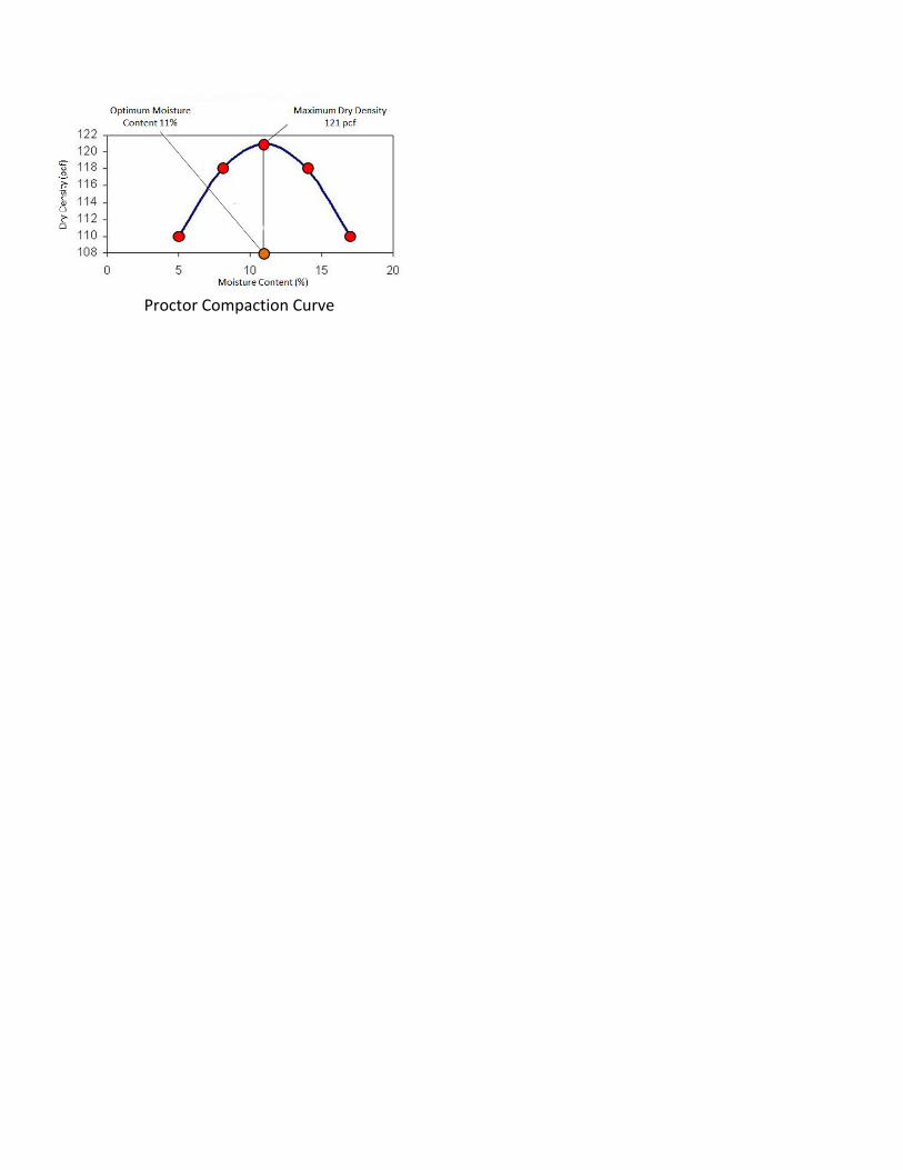
Proctor Compaction Curve

Chapter Four: Failure Analysis in
Retaining Walls
Failure Analysis
Failure Analysis
When we discuss active and passive lateral earth pressure, there are two classical theories of failure analysis that are widely used:
Rankine Earth Pressure Theory
Coulomb Earth Pressure Theory
Rankine Theory
Rankine Theory
This theory assumes that there is no wall friction, that the ground and failure surfaces are straight planes, and that the resultant force acts parallel to the backfill slope. The Rankine formula for passive pressure can only be used correctly when the embankment slope angle equals zero or is negative. If a large wall friction value can be developed, the Rankine Theory is not correct and will give less conservative results. Rankine's theory is not intended to be used for determining earth pressures directly against a wall. This theory is intended to be used for determining earth pressures on a vertical plane within a soil mass. When we use the Rankine Theory:
• No adhesion or friction exists between the wall face and soil
Rankine method is also applicable to inclined slopes as long as it is not a broken slope
• Lateral pressure is applied only to vertical walls
• Failure (in the backfill) occurs as a sliding wedge along an assumed failure plane defined by φ
• Lateral pressure varies linearly with depth
• The resultant pressure is located one-third of the height (H) above the base of the wall
• The resultant force is parallel to the backfill surface
• Coulomb w/ a frictionless wall gives the same results as Rankine
• For sloping backfill, the resultant is parallel to the slope
Coulomb Theory
Coulomb Theory
This theory provides a method of analysis that gives the resultant horizontal force on a retaining system for any slope of wall, wall friction, and slope of backfill provided. It is based on the assumption that soil shear resistance develops along the wall and failure plane.
When using the Coulomb Theory, procedures are similar to Rankine with these exceptions:
• Friction exists between the wall face and soil
• Accounts for friction by using a soil-wall friction angle of δ (which ranges from φ/2 to 2φ/3)
• Lateral pressure is not applied only to vertical walls
• Resultant force not necessarily parallel to the backfill surface because of the soil-wall friction value
• Coulomb theory considers angle of slope
Retaining Wall Failures
Some common causes of inadequate wall design resulting in failure typically arise from:
neglecting surcharge forces from other walls
designing for a level backfill surface when the backfill surface is actually sloped
using cohesive soils for the backfill
Note: Conditions for the Coulomb Theory, such
as wall friction and sloping backfill are not
discussed in this course.
not taking into account heavy stormwater conditions which may overload the drainage system
Types of Failure Modes
Overturning Failure Mode
Overturning failure is evident when the wall rotates about its bottom front edge (also called the toe of the wall). This occurs when the sum of the moments tending to cause overturning is greater than the sum of the moments resisting overturning. As with sliding failures, overturning failures usually result from an underestimation of the driving forces.
Overturning Equilibrium
The wall will remain in equilibrium in overturning, if the forces about the moment center resisting overturning are greater than or equal to the forces about the moment center causing overturning. The forces resisting overturning are the frictional resistance at the wall base, and the soil in front of the wall base.
Sliding Failure Mode
Sliding failure is when the wall moves forward, and the wall remains upright. This failure occurs when the horizontal forces which cause sliding are greater than the horizontal forces resisting the sliding. Usually, this occurs when either the driving force is underestimated or the resisting force is overestimated.
Sliding Equilibrium
The wall will remain in equilibrium in sliding, if the force resisting sliding is greater than or equal to the force causing sliding. The forces resisting sliding are the frictional resistance at the wall base, and the soil in front of the wall base.
Bearing Capacity Failure
This type of failure occurs beneath the base of the wall, due to the vertical component (vector) of the resultant lateral earth pressure force, and the gravitational forces acting vertical on the soil beneath the base.
Bearing Capacity Equilibrium
Bearing capacity failure results from shear stresses induced when the footing’s vertical pressure exceeds the shear strength of the soil. Generally, failure occurs due to an underestimation of the allowable bearing pressure of the soil for the base of the retaining wall. Long term pressure (based on an effective stress calculation) should be used while short-term bearing capacity should only be used in saturated clays.
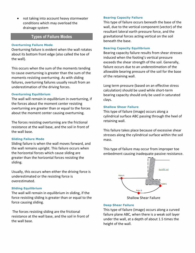
Shallow Shear Failure
This type of failure (image) occurs along a cylindrical surface ABC passing through the heel of retaining wall. This failure takes place because of excessive shear stresses along the cylindrical surface within the soil mass. This type of failure may occur from improper toe embedment causing inadequate passive resistance.
Shallow Shear Failure
Deep Shear Failure
This type of failure (image) occurs along a curved failure plane ABC, when there is a weak soil layer under the wall, at a depth of about 1.5 times the height of the wall.
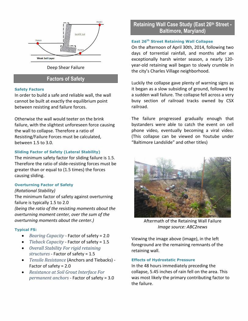
Deep Shear Failure
Factors of Safety
Safety Factors
In order to build a safe and reliable wall, the wall cannot be built at exactly the equilibrium point between resisting and failure forces. Otherwise the wall would teeter on the brink failure, with the slightest unforeseen force causing the wall to collapse. Therefore a ratio of Resisting/Failure Forces must be calculated, between 1.5 to 3.0.
Sliding Factor of Safety (Lateral Stability)
The minimum safety factor for sliding failure is 1.5. Therefore the ratio of slide-resisting forces must be greater than or equal to (1.5 times) the forces causing sliding.
Overturning Factor of Safety
(Rotational Stability) The minimum factor of safety against overturning failure is typically 1.5 to 2.0 (being the ratio of the resisting moments about the overturning moment center, over the sum of the overturning moments about the center.)
Typical FS:
Bearing Capacity - Factor of safety = 2.0
Tieback Capacity - Factor of safety = 1.5
Overall Stability For rigid retaining structures - Factor of safety = 1.5
Tensile Resistance (Anchors and Tiebacks) - Factor of safety = 2.0
Resistance at Soil Grout Interface For permanent anchors - Factor of safety = 3.0
Retaining Wall Case Study (East 26th Street - Baltimore, Maryland)
East 26th Street Retaining Wall Collapse
On the afternoon of April 30th, 2014, following two days of torrential rainfall, and months after an exceptionally harsh winter season, a nearly 120-year-old retaining wall began to slowly crumble in the city’s Charles Village neighborhood. Luckily the collapse gave plenty of warning signs as it began as a slow subsiding of ground, followed by a sudden wall failure. The collapse fell across a very busy section of railroad tracks owned by CSX railroad. The failure progressed gradually enough that bystanders were able to catch the event on cell phone video, eventually becoming a viral video. (This collapse can be viewed on Youtube under “Baltimore Landslide” and other titles)
Aftermath of the Retaining Wall Failure
Image source: ABC2news Viewing the image above (image), in the left foreground are the remaining remnants of the retaining wall.
Effects of Hydrostatic Pressure
In the 48 hours immediately preceding the collapse, 5.45 inches of rain fell on the area. This was most likely the primary contributing factor to the failure.

However, as this was not an unusually extreme rainfall for the Baltimore area, other factors also played a big role. In 1998, a similarly built section of wall required a major overhaul. As the retaining structure was built around the turn of the last century, it is likely that either the drainage system was compromised, or even non-existent.
Surcharge loading of the Line of Automobiles
Along the top of the wall, and within the backfill failure zone, were twelve parked automobiles. When this wall was originally constructed, automobiles were not the common mode of transportation. Therefore when the engineers of the time designed this retaining wall, they had no idea that such a heavy surcharge load would one day be imposed upon the wall.
Additional Surcharge load of the Sidewalk
Concrete Mass
Though it is a minor surcharge load, the weight of the overlying sidewalk could have played a minor role in the demise of the wall, as well. The specific weight of standard concrete is around 150 lbs per cubic foot while the weight of that same soil mass (if it was a dense, uniformly graded sand), is around 110 lbs. per cubic foot.
Positioning of Automobiles Following the
Collapse
One observation worth noting is the positioning of the cars following the collapse of the wall. A majority of the cars are still upright, suggesting that the “bottom was dropped out from beneath” the cars. This possibly suggests that the backfilled soil mass movement was fluid, and that the soil mass was in a saturated state, acting as it would in a mudslide situation.
Linear Cracks in Pavement
Based on images obtained from a Google Earth screenshot, there were linear cracks in the road
surface prior to the retaining wall’s collapse. These cracks were likely a fore warning of the impending wall failure. The cracks could be an indication of a readjusting soil mass. Additionally, these cracks may have been a channel for the stormwater to infiltrate behind the retaining structure.
Problems with the Wall for Years
Local residents had long complained to city officials concerning the state of the wall. Among the local residents filing suit against the city and railway company, it was commented that evidence of the eventual collapse of this wall was foreseen years prior. According to the city's report, local residents had repeatedly reported potholes, caving sidewalks, soil erosion, settlement and other problems along the area (image). Both the city of Baltimore, and CSX responded by sending inspectors, who in turn recommended making minor repairs. However, none of these inspections were conducted by qualified structural or geotechnical engineers. Additionally, there were no engineering studies performed on the wall or sidewalk, and no definite determination of the cause. The city had decided prior to the collapse that a more comprehensive rehabilitation project was required, but the $350,000 projected cost indicated to what degree, the officials were misinformed about the true nature of the wall’s condition.
Linear Cracks in the Pavement
(observed prior to collapse) Image source: Google Earth

Previous Winter Season was a Possible Minor
Contributing Factor as Well
From interviews with the Baltimore city mayor, it was disclosed that in the months prior to the failure, there had been an exceptionally harsh winter season. Factors that possibly could have had a minor contribution to the failure are heavy snow surcharge loading, and the freeze/thaw cycling of the water penetrating the roadway cracks, acting to weaken the shear strength of the soil mass.
Financial Costs and Local Headaches
It was fortunate that the wall collapse did not cause injury or loss of life. However the property loss was estimated at around $13 million for reconstruction costs (of which the railroad paid half, and the city paid the other half). Additional costs and headaches due to the collapse:
19 houses in the area were evacuated for weeks
temporary housing expenses for local displaced residents
gas mains were shut down
water mains were shut off
area traffic congestion was increased
one of CSX’s busiest sections of track was shut down
the road required reconstruction
local businesses were heavily affected, with some shutting down permanently
a local school was shut down for a period of time
the neighborhood was subjected to heavy construction noise and vibrations, for over a year.
Pending lawsuits will likely run the total cost much higher, as well
Potential of Being a Major Disaster Situation
It was also very fortunate that at the time of the collapse, no CSX train was approaching this section of track. This could have been a disaster of monumental proportion if, say a train with hazardous chemicals
or flammable liquids, had been barreling down the railroad, and hit the soil mass, derailing a long section of cars into the upcoming tunnel. As this was in the heart of one of America’s most populated cities, the injuries and loss of life could have been substantial. Additionally, given the close proximity of multi-story buildings and the overlying busy road, it was good fortune that no structures were involved in the collapse, or occupied passerby vehicles.
Rebuilding of the Wall Following the Collapse
Reconstruction of Wall
The city and railway company were able to have the wall rebuilt (images below) with a much better design. Using modern earth retention principles, the contractor was able to build a reinforced concrete wall with anchors which went down into the bedrock.
Rebuilding of the Wall Following the Collapse
Image source: Baltimore Sun
New Retaining Wall at East 26th Street
Image source: Baltimore Sun