early-stage assessment of the impacts of next generation...
TRANSCRIPT
Presenter:
Code:
Early-Stage Assessment of the
Impacts of Next Generation
Combat Power and Energy
Systems on Navy Ships
Presenter: Dr. Douglas Rigterink
Code: 823
Dr. Douglas Rigterink
[email protected] | 301-227-5886
Robert Ames (ONR)
Dr. Alexander Gray (NSWC-Carderock)
Dr. Norbert Doerry (NAVSEA 05T)
2/13
Agenda
• The Future of High Energy Combat Power and Energy Systems
• The Combat Power and Energy Systems Overarching
Integrated Product Team (OIPT)
• System Patterns and Templates
• Systems Patterns and Templates in Ship Design
• The Smart Ship Systems Design (S3D) Tool
• The LEAPS design environment
• The ASSET Ship Synthesis Tool
• S3D and ASSET for Point-Based Design
• Using Patterns and Templates for Set-Based Design
• Our Next Steps
The Future of High Energy Combat Power and Energy Systems
3/13
• Within the next 4 years, a new high energy system will come
online every 2 years
• Several of these systems will require similar enabling power
technologies: • Power converters
• Energy storage
• Control
• Integration efforts must be streamlined & focused to save time,
money, and ensure success by: • Sharing lessons learned and leveraging investments
• Seeking common solutions for similar issues
• Schedule and budget coordination
• To bring stakeholders together an OIPT co-chaired by PEO
Ships and NAVSEA 05 was formed with representation from
modernization, new construction, resource sponsor, and R&D
communities.
CPES OIPT Organization
4/13
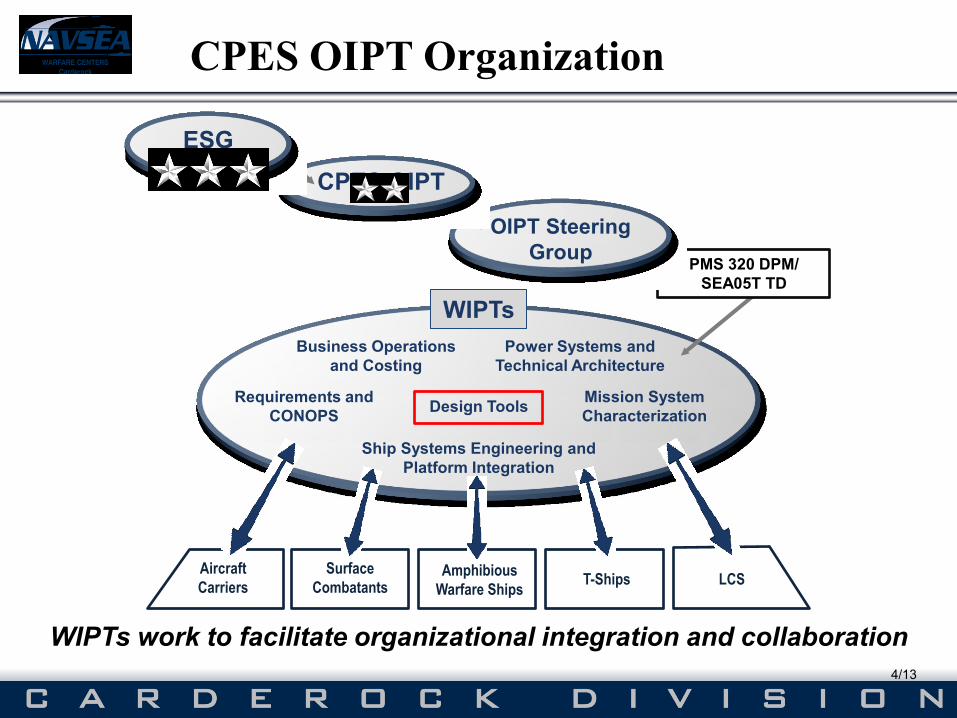
WIPTs work to facilitate organizational integration and collaboration
Requirements and
CONOPS
Ship Systems Engineering and
Platform Integration
Design Tools
Power Systems and
Technical Architecture
Mission System
Characterization
PMS 320 DPM/
SEA05T TD
OIPT Steering
Group
CPES OIPT
ESG
WIPTs
Business Operations
and Costing
Amphibious
Warfare Ships LCS T-Ships
Surface
Combatants
Aircraft
Carriers
Design Tools & Methodology Working Integrated Product Team
5/13
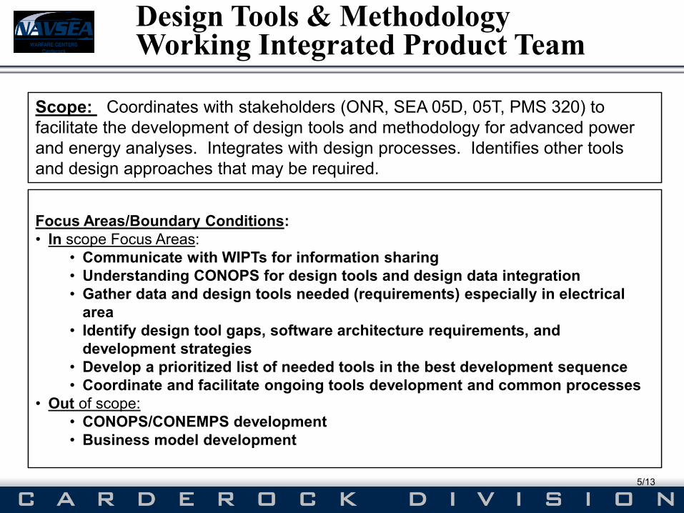
Scope: Coordinates with stakeholders (ONR, SEA 05D, 05T, PMS 320) to
facilitate the development of design tools and methodology for advanced power
and energy analyses. Integrates with design
and design
Scope: Coordinates with stakeholders (ONR, SEA 05D, 05T, PMS 320) to
facilitate the development of design tools and methodology for advanced power
and energy analyses. Integrates with design processes. Identifies other tools
and design approaches that may be required.
Focus Areas/Boundary Conditions
•
•
Focus Areas/Boundary Conditions:
• In scope Focus Areas:
• Communicate with WIPTs for information sharing
• Understanding CONOPS for design tools and design data integration
• Gather data and design tools needed (requirements) especially in electrical
area
• Identify design tool gaps, software architecture requirements, and
development strategies
• Develop a prioritized list of needed tools in the best development sequence
• Coordinate and facilitate ongoing tools development and common processes
• Out of scope:
• CONOPS/CONEMPS development
• Business model development
Ship System Patterns and Templates
6/13
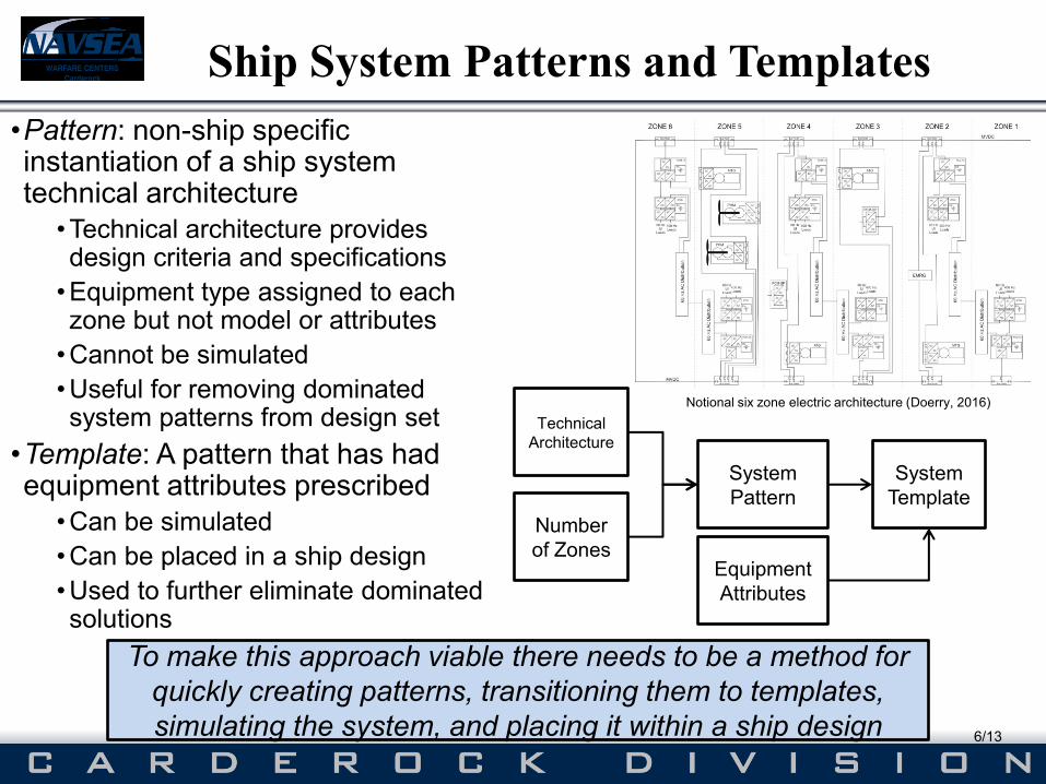
•Pattern: non-ship specific instantiation of a ship system technical architecture
•Technical architecture provides design criteria and specifications
•Equipment type assigned to each zone but not model or attributes
•Cannot be simulated
•Useful for removing dominated system patterns from design set
•Template: A pattern that has had equipment attributes prescribed
•Can be simulated
•Can be placed in a ship design
•Used to further eliminate dominated solutions
System
Template
System
Pattern
Number
of Zones
Technical
Architecture
Equipment
Attributes
To make this approach viable there needs to be a method for
quickly creating patterns, transitioning them to templates,
simulating the system, and placing it within a ship design
Notional six zone electric architecture (Doerry, 2016)
Smart Ship Systems Design (S3D) Tool
7/13
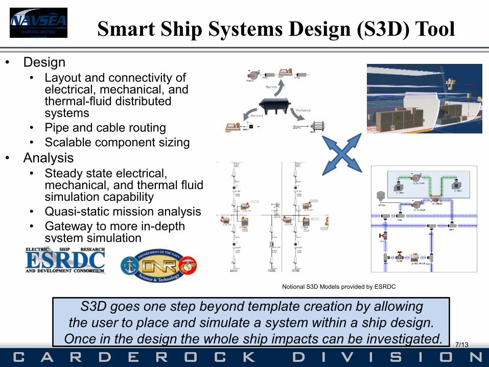
• Design • Layout and connectivity of
electrical, mechanical, and thermal-fluid distributed systems
• Pipe and cable routing
• Scalable component sizing
• Analysis • Steady state electrical,
mechanical, and thermal fluid simulation capability
• Quasi-static mission analysis
• Gateway to more in-depth system simulation
S3D goes one step beyond template creation by allowing
the user to place and simulate a system within a ship design.
Once in the design the whole ship impacts can be investigated.
Notional S3D Models provided by ESRDC
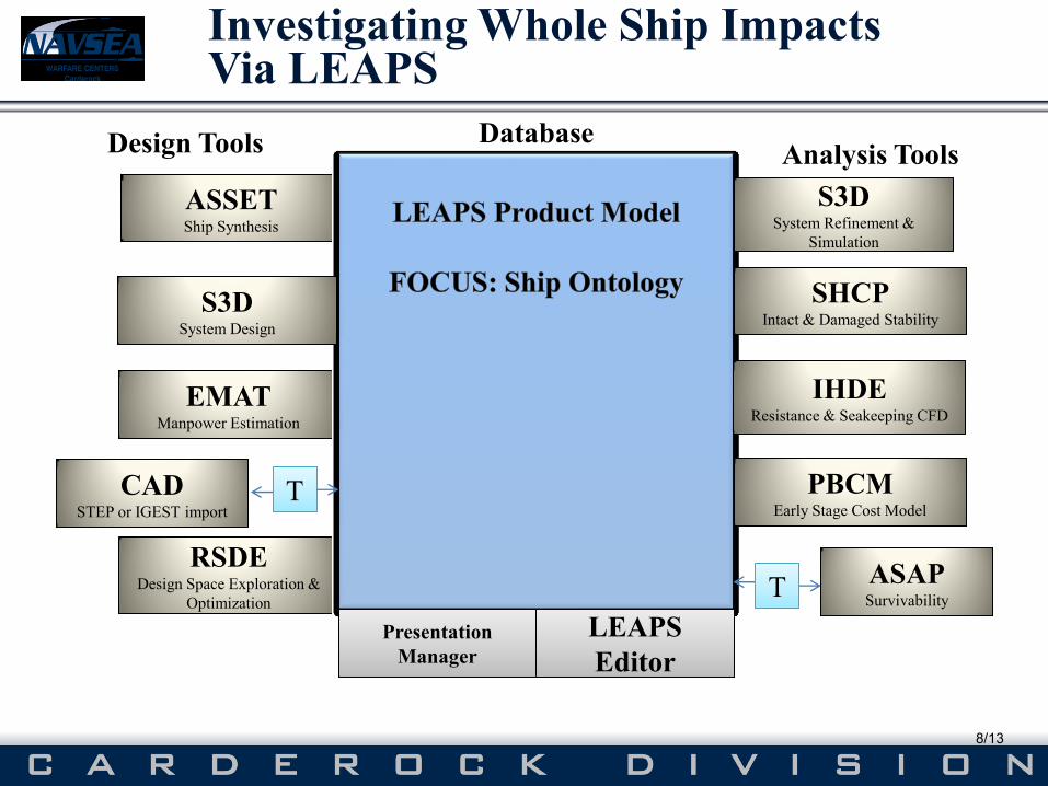
ASSET ASSET Ship Synthesis
EMAT EMAT Manpower Estimation
RSDE RSDE Design Space Exploration &
Optimization
Database
T T
Presentation
Manager
LEAPS
Editor
LEAPS
Editor
Design Tools Analysis Tools
PBCM PBCM Early Stage Cost Model
T T
CAD CAD STEP or IGEST import
IHDE Resistance & Seakeeping CFD
SHCP SHCP Intact & Damaged Stability
ASAP ASAP Survivability
S3D S3D System Design
S3D
Simulation
S3D System Refinement &
Simulation
Investigating Whole Ship Impacts Via LEAPS
8/13
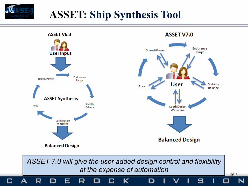
ASSET: Ship Synthesis Tool
9/13
ASSET 7.0 will give the user added design control and flexibility
at the expense of automation
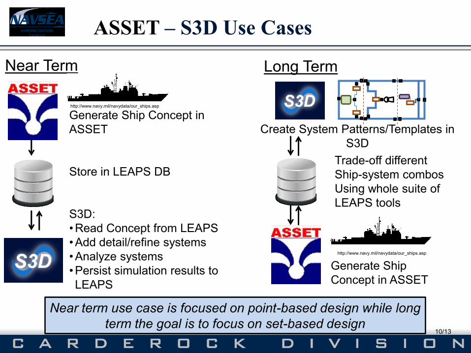
Generate Ship Concept in
ASSET
Store in LEAPS DB
S3D:
•Read Concept from LEAPS
•Add detail/refine systems
•Analyze systems
•Persist simulation results to
LEAPS
ASSET – S3D Use Cases
10/13
Create System Patterns/Templates in
S3D
Generate Ship
Concept in ASSET
Trade-off different
Ship-system combos
Using whole suite of
LEAPS tools
Long Term Near Term
Near term use case is focused on point-based design while long
term the goal is to focus on set-based design
http://www.navy.mil/navydata/our_ships.asp
http://www.navy.mil/navydata/our_ships.asp
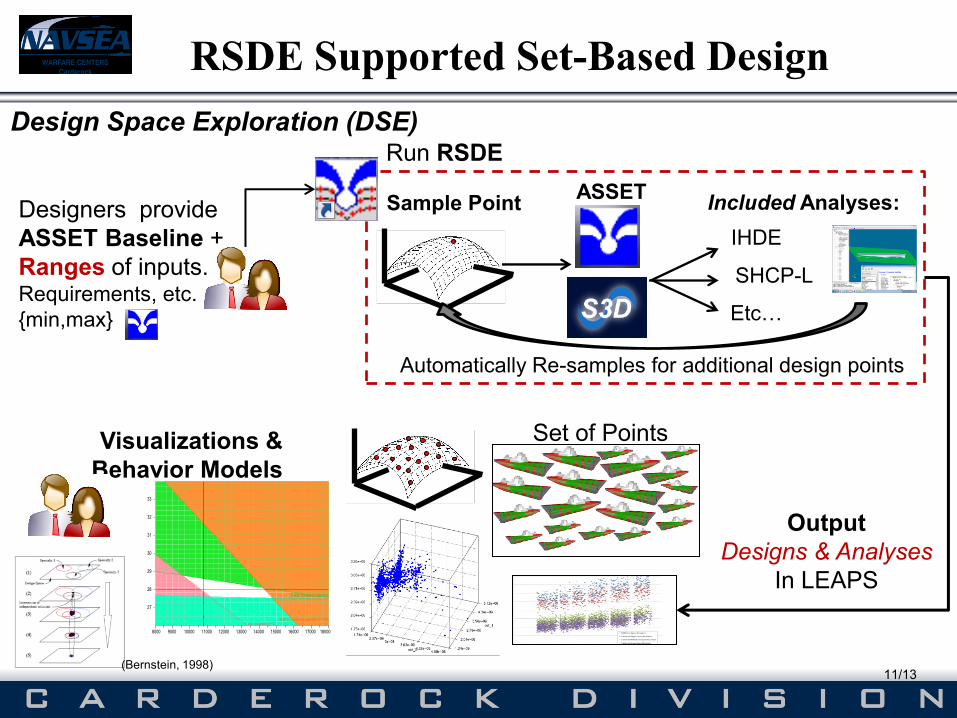
Designers provide
ASSET Baseline +
Ranges of inputs. Requirements, etc.
{min,max}
ASSET
IHDE
SHCP-L
Etc…
Included Analyses:
Run RSDE
Sample Point
Automatically Re-samples for additional design points
Output
Designs & Analyses
In LEAPS
Visualizations &
Behavior Models
Design Space Exploration (DSE)
(Bernstein, 1998)
RSDE Supported Set-Based Design
11/13
Set of Points
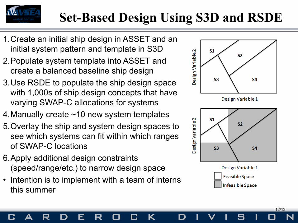
Set-Based Design Using S3D and RSDE
12/13
1.Create an initial ship design in ASSET and an
initial system pattern and template in S3D
2.Populate system template into ASSET and
create a balanced baseline ship design
3.Use RSDE to populate the ship design space
with 1,000s of ship design concepts that have
varying SWAP-C allocations for systems
4.Manually create ~10 new system templates
5.Overlay the ship and system design spaces to
see which systems can fit within which ranges
of SWAP-C locations
6.Apply additional design constraints
(speed/range/etc.) to narrow design space
• Intention is to implement with a team of interns
this summer
Questions?
13/13
Early-Stage Assessment of the impacts of Next
Generation Combat Power and Energy Systems on
Navy Ships
Dr. Douglas Rigterink (NSWC-Carderock)
[email protected] | 301-227-5886
The authors would like to thank:
Kelly Cooper, ONR
Julie Chalfant, MIT & ESRDC
Blake Langland, University of South Carolina & ESRDC
Dave Woodward, Sean Gallagher, Mike Robinson, Jim Carlson, NSWC-Philadelphia
Todd Heidenreich, Keawe Van Eseltine, NSWC-Carderock
Dave Helgerson
Dan Billingsley