eagle xg diameter signaling router - oracle help center · viewing peer route tables ... viewing...
TRANSCRIPT

EAGLE® XG Diameter SignalingRouter
Diameter and Mediation User Guide910-6822-001 Revision A
November 2013
Copyright 2013 Tekelec. All Rights Reserved. Printed in USA.Legal Information can be accessed from the Main Menu of the optical disc or on the
Tekelec Customer Support web site in the Legal Information folder of the Product Support tab.

Table of Contents
Chapter 1: Introduction...............................................................................18Overview...............................................................................................................................................19Scope and Audience............................................................................................................................19Document Organization......................................................................................................................19Documentation Admonishments.......................................................................................................20Related Publications............................................................................................................................20Customer Care Center.........................................................................................................................21Emergency Response...........................................................................................................................23Locate Product Documentation on the Customer Support Site....................................................24
Chapter 2: Configuration............................................................................25Configuration Sequence......................................................................................................................27Configuration Capacity Summary.....................................................................................................28Connection Capacity Validation........................................................................................................29
Connection Capacity Dashboard Page..................................................................................32MP Profiles............................................................................................................................................36
MP Profiles elements...............................................................................................................37Viewing MP Profiles................................................................................................................40Editing Configurable MP Profile Parameters......................................................................41Assigning MP Profiles to DA-MPs........................................................................................41
Application Ids configuration............................................................................................................42Application Ids elements........................................................................................................43Viewing Application Ids.........................................................................................................44Adding an Application Id.......................................................................................................45Editing an Application Id........................................................................................................46Deleting an Application Id.....................................................................................................46
CEX Parameters configuration...........................................................................................................47CEX Parameters elements.......................................................................................................47Viewing CEX Parameters........................................................................................................48Adding CEX Parameters.........................................................................................................48Editing CEX Parameters..........................................................................................................49Deleting CEX Parameters........................................................................................................50
Command Codes configuration.........................................................................................................50Command Codes elements.....................................................................................................51
2910-6822-001 Revision A, November 2013
Viewing Command Codes......................................................................................................51Adding a Command Code......................................................................................................51Editing a Command Code......................................................................................................52Deleting a Command Code....................................................................................................53
MCC Ranges configuration................................................................................................................53MCC Ranges elements.............................................................................................................54Viewing MCC Ranges.............................................................................................................54Adding MCC Ranges...............................................................................................................55Editing MCC Ranges...............................................................................................................55Deleting MCC Ranges.............................................................................................................56
Connection Configuration Set configuration...................................................................................56Connection Configuration Set elements...............................................................................57Viewing Connection Configuration Sets..............................................................................62Adding a Connection Configuration Set..............................................................................62Editing a Connection Configuration Set...............................................................................62Deleting a Connection Configuration Set.............................................................................63
CEX Configuration Set configuration...............................................................................................64CEX Configuration Set elements............................................................................................65Viewing CEX Configuration Sets...........................................................................................66Adding a CEX Configuration Set...........................................................................................66Editing a CEX Configuration Set...........................................................................................67Deleting a CEX Configuration Set.........................................................................................68
Capacity Configuration Set configuration........................................................................................68Capacity Configuration Set elements....................................................................................70Viewing Capacity Configuration Sets...................................................................................71Adding a Capacity Configuration Set...................................................................................71Editing a Capacity Configuration Set....................................................................................72Deleting a Capacity Configuration Set..................................................................................73
Egress Message Throttling Configuration Set configuration.........................................................73Egress Message Throttling Configuration Set elements.....................................................74Viewing Egress Message Throttling Configuration Sets....................................................75Adding an Egress Message Throttling Configuration Set.................................................75Editing an Egress Message Throttling Configuration Set..................................................76Deleting an Egress Message Throttling Configuration Set................................................77
Message Priority Configuration Set configuration..........................................................................77Message Priority Configuration Set elements......................................................................78Viewing Message Priority Configuration Sets.....................................................................79Adding a Message Priority Configuration Set.....................................................................79Editing a Message Priority Configuration Set.....................................................................80Deleting a Message Priority Configuration Set...................................................................81
Message Copy Configuration Set configuration.............................................................................81
3910-6822-001 Revision A, November 2013

Message Copy Configuration Set elements..........................................................................82Viewing Message Copy Configuration Sets.........................................................................83Adding a Message Copy Configuration Set.........................................................................83Editing a Message Copy Configuration Set.........................................................................84Deleting a Message Copy Configuration Set.......................................................................84
Local Node configuration...................................................................................................................85Local Node configuration elements.......................................................................................86Viewing Local Nodes...............................................................................................................88Adding a Local Node...............................................................................................................88Editing a Local Node...............................................................................................................89Deleting a Local Node.............................................................................................................90
Peer Node configuration.....................................................................................................................91Peer Node configuration elements........................................................................................92Viewing Peer Nodes................................................................................................................96Adding a Peer Node................................................................................................................96Editing a Peer Node.................................................................................................................98Deleting a Peer Node...............................................................................................................99
Connection configuration...................................................................................................................99Connection configuration elements.....................................................................................101Viewing Connections.............................................................................................................109Adding a Connection ............................................................................................................110Editing a Connection.............................................................................................................112Deleting a Connection...........................................................................................................114
Route Group configuration...............................................................................................................115Route Group configuration elements..................................................................................115Viewing Route Groups..........................................................................................................117Adding a Route Group..........................................................................................................117Editing a Route Group...........................................................................................................118Deleting a Route Group........................................................................................................119
Route List configuration....................................................................................................................119Route List configuration elements.......................................................................................120Viewing Route Lists...............................................................................................................121Adding a Route List...............................................................................................................122Editing a Route List................................................................................................................122Deleting a Route List.............................................................................................................123
Peer Route Tables configuration......................................................................................................123Peer Route Tables elements..................................................................................................124Viewing Peer Route Tables...................................................................................................124Adding a Peer Route Table...................................................................................................124Deleting a Peer Route Table..................................................................................................125Peer Routing Rules configuration........................................................................................125
4910-6822-001 Revision A, November 2013
Egress Throttle Groups configuration.............................................................................................133Egress Throttle Groups elements.........................................................................................134Viewing Egress Throttle Groups..........................................................................................137Adding Egress Throttle Groups...........................................................................................137Editing Egress Throttle Groups............................................................................................139Deleting Egress Throttle Groups.........................................................................................139
Reroute On Answer configuration..................................................................................................140Reroute On Answer configuration elements......................................................................140Viewing Reroute On Answer...............................................................................................141Adding a Reroute On Answer entry...................................................................................141Deleting a Reroute On Answer............................................................................................142
Application Route Tables configuration.........................................................................................142Application Route Tables elements.....................................................................................143Viewing Application Route Tables......................................................................................143Adding an Application Route Table...................................................................................143Deleting an Application Route Table..................................................................................144Application Routing Rules configuration...........................................................................144
Routing Option Sets configuration..................................................................................................152Routing Option Sets elements..............................................................................................152Viewing Routing Option Sets...............................................................................................156Adding a Routing Option Set...............................................................................................156Editing a Routing Option Set...............................................................................................157Deleting a Routing Option Set.............................................................................................157
Pending Answer Timers configuration...........................................................................................158Pending Answer Timers elements.......................................................................................161Viewing Pending Answer Timers........................................................................................162Adding a Pending Answer Timer........................................................................................162Editing a Pending Answer Timer........................................................................................162Deleting a Pending Answer Timer......................................................................................163
System Options configuration..........................................................................................................163System Options elements......................................................................................................164
DNS Options configuration..............................................................................................................166DNS Options elements..........................................................................................................167
Topology Hiding configuration.......................................................................................................167Diameter Topology Hiding...................................................................................................167Trusted Networks Lists configuration................................................................................189Path Topology Hiding Configuration Set configuration..................................................192S6a/S6d HSS Topology Hiding Configuration Set configuration..................................197MME/SGSN Topology Hiding Configuration Set configuration...................................200Protected Networks configuration......................................................................................206
DSR Bulk Import................................................................................................................................209
5910-6822-001 Revision A, November 2013

Bulk Import elements............................................................................................................215Using an Import file to insert DSR configuration data.....................................................216Using an Import file to update DSR configuration data..................................................216Using an Import file to delete DSR configuration data....................................................217
DSR Bulk Export.................................................................................................................................218Bulk Export elements.............................................................................................................220Manually Exporting a configuration data file once..........................................................223Scheduling periodic automatic exports of configuration data........................................224Bulk Import and Export CSV File Formats and Contents................................................225
Chapter 3: Diameter Message Copy.......................................................259Diameter Message Copy overview..................................................................................................260Diameter Message Copy feature......................................................................................................262
Chapter 4: Maintenance............................................................................270Overview.............................................................................................................................................271Route List maintenance.....................................................................................................................271
Route List maintenance elements........................................................................................271Viewing Route List status.....................................................................................................272
Route Group maintenance................................................................................................................272Route Group maintenance elements...................................................................................273Viewing Route Group status................................................................................................274
Peer Node maintenance....................................................................................................................274Peer Node maintenance elements........................................................................................274Viewing Peer Node status.....................................................................................................275
Connection maintenance...................................................................................................................275Connection maintenance elements......................................................................................276Viewing Connection status...................................................................................................278Enabling Connections............................................................................................................279Enabling All Connections.....................................................................................................279Disabling Connections...........................................................................................................279Disabling All Connections....................................................................................................280Viewing statistics for an SCTP connection.........................................................................280Starting Diagnosis on a Test Connection............................................................................281Ending Diagnosis on a Test Connection.............................................................................281
Egress Throttle Groups maintenance..............................................................................................282Egress Throttle Groups maintenance elements.................................................................284Viewing Egress Throttle Groups status..............................................................................285Enabling Egress Throttle Groups Rate Limiting................................................................286Disabling Egress Throttle Groups Rate Limiting..............................................................286
6910-6822-001 Revision A, November 2013

Enabling Egress Throttle Groups Pending Transaction Limiting...................................287Disabling Egress Throttle Groups Pending Transaction Limiting..................................287
Application maintenance..................................................................................................................288Applications maintenance elements....................................................................................288Viewing Application status..................................................................................................289Enabling Applications...........................................................................................................289Disabling Applications..........................................................................................................289
DA-MP maintenance.........................................................................................................................290DA-MPs maintenance elements...........................................................................................290Viewing DA-MP status..........................................................................................................292
Chapter 5: Reports......................................................................................293Overview.............................................................................................................................................294Generating Diagnostics Tool Reports..............................................................................................294
Viewing, Printing, and Saving Diagnostics Tool Reports................................................295Updating and Viewing MP Statistics (SCTP) Reports..................................................................296
MP Statistics (SCTP) report elements..................................................................................296
Chapter 6: Diameter Mediation...............................................................299Mediation overview...........................................................................................................................300Rule Templates...................................................................................................................................302
Rule Template elements........................................................................................................305Viewing Rule Templates.......................................................................................................321Adding a Rule Template.......................................................................................................321Adding online help to a Rule Template..............................................................................323Copying a Rule Template.....................................................................................................324Changing a Rule Template...................................................................................................325Importing a Rule Template...................................................................................................325Exporting a Rule Template...................................................................................................327Deleting a Rule Template......................................................................................................327
Formatting Value Wizard.................................................................................................................328Formatting Value Wizard elements.....................................................................................328Using the Formatting Value Wizard...................................................................................336
Enumerations......................................................................................................................................336Mediation Enumerations elements......................................................................................337Viewing Enumerations..........................................................................................................338Adding an Enumeration.......................................................................................................338Editing an Enumeration........................................................................................................339Deleting an Enumeration......................................................................................................339
Triggers................................................................................................................................................340
7910-6822-001 Revision A, November 2013
Mediation Triggers elements................................................................................................341Viewing Triggers....................................................................................................................342Associating a Rule Set with a Trigger.................................................................................342Removing the Association of a Rule Set with a Trigger...................................................343
State and Properties...........................................................................................................................344Mediation State & Properties elements...............................................................................345Importing a Rule Template...................................................................................................346Editing State and Properties.................................................................................................346Deleting a Rule Template......................................................................................................347
Base Dictionary...................................................................................................................................348Mediation Base Dictionary elements...................................................................................348Viewing an existing AVP Dictionary entry........................................................................350
Custom Dictionary.............................................................................................................................350Mediation Custom Dictionary elements.............................................................................351Adding a new AVP Dictionary entry..................................................................................353Changing an existing AVP Dictionary entry.....................................................................354Deleting an AVP dictionary entry.......................................................................................354
All-AVP Dictionary............................................................................................................................355Mediation All-AVP Dictionary elements............................................................................355Viewing an existing All-AVP Dictionary entry definition...............................................357
Vendors................................................................................................................................................357Mediation Vendors elements................................................................................................358Viewing Vendors....................................................................................................................358Adding a Vendor....................................................................................................................358Editing a Vendor Name.........................................................................................................359Deleting a Vendor..................................................................................................................360
Rule Sets...............................................................................................................................................360User-defined Rule Sets..........................................................................................................362Rule Sets elements - View page............................................................................................363Rule Sets elements - Insert and Edit Pages.........................................................................364Adding a Rule to a Rule Set..................................................................................................365Deleting All Rules from a Rule Set......................................................................................367Changing a Rule in a Rule Set..............................................................................................367Deleting One Rule from a Rule Set......................................................................................367
Chapter 7: DSR Capacity and Congestion Controls............................369Introduction........................................................................................................................................370DA-MP Overload Control.................................................................................................................370Per-Connection Ingress MPS Control.............................................................................................372Remote Congestion Controls............................................................................................................376
8910-6822-001 Revision A, November 2013

User Configurable Message Priority...................................................................................379Remote BUSY Congestion.....................................................................................................382Egress Transport Congestion...............................................................................................384Per Connection Egress Message Throttling........................................................................385User Configurable Connection Pending Transaction Limiting.......................................388
Egress Throttle Groups......................................................................................................................389Glossary.............................................................................................................................395
9910-6822-001 Revision A, November 2013

List of Figures
Figure 1: Connection Capacity Dashboard Connections Tab....................................................................32
Figure 2: Diameter Topology Hiding Boundary.......................................................................................169
Figure 3: Diameter Topology Hiding Trigger Points: Protected-to-Untrusted Transactions.............170
Figure 4: Diameter Topology Hiding Trigger Points: Untrusted-to-Protected Transactions.............170
Figure 5: TH Network Deployment with DSR in an Interworking Network.......................................173
Figure 6: S6a/S6d HSS TH Protected-HSS to Untrusted-MME/SGSN Diameter Transaction..........179
Figure 7: S6a/S6d HSS TH Untrusted-MME/SGSN to Protected-HSS Transaction...........................180
Figure 8: MME/SGSN TH Protected-MME/SGSN to Untrusted HSS Transaction............................183
Figure 9: MME/SGSN TH Untrusted-HSS to Protected MME/SGSN Transaction............................184
Figure 10: Route-Record Hiding - Request Message................................................................................185
Figure 11: Route-Record Hiding - Answer Message.................................................................................186
Figure 12: Multi-DEA Route-Record Message Loop Detection...............................................................186
Figure 13: Unsupported Pseudo-Host Route-Record Loop Detection...................................................187
Figure 14: Proxy-Host Hiding......................................................................................................................188
Figure 15: Error-Reporting-Host AVP Hiding...........................................................................................189
Figure 16: Diameter Message Copy Message Flow...................................................................................261
Figure 17: Diameter Mediation Trigger Points..........................................................................................341
Figure 18: Per Connection Message Coloring............................................................................................373
10910-6822-001 Revision A, November 2013

List of Tables
Table 1: Admonishments................................................................................................................................20
Table 2: MP Profile Selection..........................................................................................................................36
Table 3: MP Profile Elements..........................................................................................................................37
Table 4: Application Ids elements..................................................................................................................43
Table 5: CEX Parameters elements................................................................................................................48
Table 6: Command Codes elements..............................................................................................................51
Table 7: MCC Ranges elements......................................................................................................................54
Table 8: Connection Configuration Sets Elements......................................................................................57
Table 9: Configuration Sets Elements............................................................................................................65
Table 10: Capacity Configuration Sets Elements.........................................................................................70
Table 11: Egress Message Throttling Configuration Set Elements...........................................................74
Table 12: Message Priority Configuration Set Elements............................................................................78
Table 13: Message Copy Configuration Set Elements................................................................................82
Table 14: Local Node Configuration Elements............................................................................................86
Table 15: Peer Node Configuration Elements..............................................................................................92
Table 16: Connections Configuration Elements.........................................................................................101
Table 17: Route Groups Configuration Elements......................................................................................116
Table 18: Route Lists Configuration Elements...........................................................................................121
Table 19: Peer Route Tables Elements.........................................................................................................124
Table 20: Peer Routing Rules Configuration Elements.............................................................................127
Table 21: Peer Routing Rules Operators.....................................................................................................130
Table 22: Egress Throttle Groups Elements................................................................................................134
11910-6822-001 Revision A, November 2013

Table 23: Reroute On Answer Configuration Elements...........................................................................141
Table 24: Application Route Tables elements............................................................................................143
Table 25: Application Routing Rules Configuration Elements...............................................................145
Table 26: Application Routing Rules Operators........................................................................................148
Table 27: Routing Option Sets Elements.....................................................................................................153
Table 28: Diameter Pending Answer Timer and Transaction Lifetime Selection.................................159
Table 29: Pending Answer Timers Elements..............................................................................................161
Table 30: System Options Elements.............................................................................................................164
Table 31: DNS Options Elements.................................................................................................................167
Table 32: Topology Information Hiding and Restoral Procedures.........................................................170
Table 33: Example Protected Networks Configuration............................................................................173
Table 34: Example Trusted Network Lists Configuration.......................................................................173
Table 35: Network Trust Relationship Matrix...........................................................................................174
Table 36: Example Topology Hiding Status Settings................................................................................174
Table 37: General Criteria for Determining Whether a Message is a TH Candidate...........................174
Table 38: Protected Network Configuration Example..............................................................................176
Table 39: Topology Hiding AVPs and Hiding Methods..........................................................................176
Table 40: Example of Configuration of MME/SGSN TH Hostnames for a Protected Network........181
Table 41: Trusted Network Lists elements.................................................................................................190
Table 42: Path Topology Hiding Configuration Sets Elements...............................................................193
Table 43: S6a/S6d HSS Topology Hiding Configuration Sets Elements...............................................198
Table 44: MME/SGSN Topology Hiding Configuration Sets Elements................................................201
Table 45: Protected Network Configuration Elements.............................................................................207
Table 46: Valid Import Operations..............................................................................................................212
Table 47: Bulk Import elements....................................................................................................................215
12910-6822-001 Revision A, November 2013

Table 48: Bulk Export elements....................................................................................................................220
Table 49: Application Types Supported by DSR Bulk Import and Export............................................225
Table 50: Local Node CSV Format...............................................................................................................226
Table 51: Peer Node CSV Format.................................................................................................................226
Table 52: Route Group CSV Format............................................................................................................227
Table 53: Route List CSV Format.................................................................................................................228
Table 54: Peer Routing Rule CSV Format...................................................................................................228
Table 55: Connection CSV Format...............................................................................................................230
Table 56: Connection Configuration Set CSV Format...............................................................................230
Table 57: Reroute on Answer CSV Format.................................................................................................232
Table 58: System Options CSV Format.......................................................................................................232
Table 59: DNS Options CSV Format............................................................................................................232
Table 60: CEX Configuration Set CSV Format...........................................................................................233
Table 61: Capacity Configuration Set CSV Format...................................................................................233
Table 62: AppRouteRule CSV Format.........................................................................................................234
Table 63: Application ID CSV Format.........................................................................................................235
Table 64: CEX Parameters CSV Format......................................................................................................235
Table 65: Pending Answer Timer CSV Format..........................................................................................236
Table 66: Routing Option Set CSV Format.................................................................................................236
Table 67: Peer Route Table CSV Format.....................................................................................................237
Table 68: Message Priority Configuration Set CSV Format.....................................................................237
Table 69: Message Throttling Configuration Set CSV Format.................................................................237
Table 70: Message Copy Configuration Set CSV Format.........................................................................238
Table 71: Application Route Table CSV Format........................................................................................238
Table 72: MP Profile CSV Format................................................................................................................239
13910-6822-001 Revision A, November 2013
Table 73: Egress Throttle Groups CSV Format..........................................................................................239
Table 74: Reserved MCC Ranges CSV Format...........................................................................................240
Table 75: Command Code CSV Format......................................................................................................240
Table 76: Trusted Network List CSV Format.............................................................................................241
Table 77: Path Topology Hiding Configuration Set CSV Format...........................................................241
Table 78: S6a/S6d HSS Topology Hiding Configuration Set CSV Format............................................241
Table 79: MME/SGSN Topology Hiding Configuration Set CSV Format............................................242
Table 80: Protected Network CSV Format..................................................................................................242
Table 81: Supported Application CSV Format...........................................................................................243
Table 82: Address Individual CSV Format.................................................................................................243
Table 83: Address Range CSV Format........................................................................................................244
Table 84: Address Table CSV Format..........................................................................................................244
Table 85: Destination Table CSV Format....................................................................................................244
Table 86: Routing Exception CSV Format..................................................................................................245
Table 87: Address Resolution CSV Format................................................................................................245
Table 88: Option CSV Format.......................................................................................................................246
Table 89: Supported Application CSV Format...........................................................................................247
Table 90: Routing Exception CSV Format..................................................................................................247
Table 91: Default Destination Table CSV Format......................................................................................248
Table 92: Address Resolution CSV Format................................................................................................248
Table 93: Option CSV Format.......................................................................................................................249
Table 94: System Option CSV Format.........................................................................................................250
Table 95: Message Copy CSV Format.........................................................................................................251
Table 96: SBR CSV Format............................................................................................................................251
Table 97: IPFE IpfeOption CSV Format......................................................................................................252
14910-6822-001 Revision A, November 2013

Table 98: IPFE IpfeListTsa CSV Format......................................................................................................253
Table 99: PCRFs CSV Format.......................................................................................................................254
Table 100: Binding Key Priority CSV Format.............................................................................................254
Table 101: Policy DRA Topology Hiding CSV Format.............................................................................254
Table 102: Policy DRA Options CSV Format.............................................................................................255
Table 103: Error Codes CSV Format............................................................................................................255
Table 104: Access Point Names CSV Format.............................................................................................256
Table 105: Alarm Settings CSV Format.......................................................................................................256
Table 106: Congestion Options CSV Format..............................................................................................257
Table 107: Tekelec-Specific MsgCopyAnswer AVP Format....................................................................264
Table 108: Portion of the Answer Message Included as Data Value of the MsgCopyAnswerAVP.............................................................................................................................................................264
Table 109: Initial Values in the Default Message Copy Configuration Set............................................268
Table 110: Route Lists Maintenance Elements...........................................................................................271
Table 111: Route Group Maintenance Elements........................................................................................273
Table 112: Peer Nodes Maintenance Elements..........................................................................................274
Table 113: Connections Maintenance Elements.........................................................................................276
Table 114: Connections SCTP Statistics Elements.....................................................................................281
Table 115: Egress Throttle Groups Admin States......................................................................................282
Table 116: ETG Operational Status..............................................................................................................282
Table 117: ETG Operational Reason............................................................................................................283
Table 118: Egress Throttle Groups Maintenance Elements......................................................................284
Table 119: Applications Maintenance Elements........................................................................................288
Table 120: DA-MPs Maintenance Elements...............................................................................................290
Table 121: MP Statistics (SCTP) Report Elements.....................................................................................296
15910-6822-001 Revision A, November 2013

Table 122: Rule Template elements.............................................................................................................305
Table 123: Rule Template Condition Operators........................................................................................318
Table 124: Rule Template Condition Conversion Rules...........................................................................320
Table 125: Formatting Value Wizard elements..........................................................................................328
Table 126: Formatting Value Wizard Specifiers........................................................................................329
Table 127: Mediation Enumeration elements.............................................................................................337
Table 128: Diameter Mediation Triggers....................................................................................................340
Table 129: Mediation Triggers elements.....................................................................................................342
Table 130: Mediation State & Properties elements....................................................................................345
Table 131: Mediation Base Dictionary Elements.......................................................................................348
Table 132: Mediation Custom Dictionary Elements..................................................................................351
Table 133: Mediation All-AVP Dictionary elements.................................................................................355
Table 134: Mediation Vendors elements.....................................................................................................358
Table 135: Example of Default Ordering of Rules in a Rule Set..............................................................361
Table 136: Rule Sets Elements - View Page................................................................................................363
Table 137: Maximum Allowed Rule Sets and Rules.................................................................................364
Table 138: Rule Sets Elements - Insert and Edit Pages..............................................................................364
Table 139: CLs, CPLs, and Message Treatment.........................................................................................377
Table 140: Mapping Congestion Levels to CPL Values............................................................................378
Table 141: Remote BUSY and EMR Capacity Ranges...............................................................................379
Table 142: Message Priority Treatment Methods......................................................................................382
Table 143: Mapping Congestion Levels to CPL Values............................................................................384
Table 144: Congestion Levels Based on Thresholds..................................................................................387
Table 145: Message Priority and ETG Congestion Level..........................................................................391
Table 146: ETG Message Rate Congestion Levels Based on Threshold.................................................391
16910-6822-001 Revision A, November 2013

Table 147: ETG Pending Transaction Congestion Levels Based on Threshold.....................................393
17910-6822-001 Revision A, November 2013

Chapter
1Introduction
The Diameter document provides information abouthow to use the DSR GUI to perform DiameterSignaling Router tasks.
Topics:
• Overview.....19• Scope and Audience.....19• Document Organization.....19• Documentation Admonishments.....20• Related Publications.....20• Customer Care Center.....21• Emergency Response.....23• Locate Product Documentation on the Customer
Support Site.....24
18910-6822-001 Revision A, November 2013

Overview
The Diameter document provides information about how to use the DSR GUI to perform DiameterSignaling Router tasks.
The document provides the following types of information:
• Procedures to configure Diameter components• Maintenance information about Diameter components• Procedures to generate reports for the Diagnostics Tool and MP Statistics• Procedures to configure Diameter Mediation Rule Templates and Rule Sets
Scope and Audience
This manual is intended for personnel who perform Diameter Signaling Router tasks.
This manual contains procedures for performing Diameter Signaling Router tasks using the DSR GUI.
This manual does not describe how to install or replace software or hardware.
Document Organization
This document is organized into the following chapters:
• Introduction contains general information about the Diameter and Mediation help documentation,the organization of this manual, and how to get technical assistance.
• Configuration provides information on configuring Diameter resources and how to do bulk importsand exports of DSR configuration data.
• Diameter Message Copy describes the Diameter Message Copy feature, which is used in the DSR tosend a copy of a message to a DAS.
• Maintenance provides information on how to view the status of Diameter resources, and how toenable and disable connections and DSR Applications.
• Reports provides information on how to produce Diagnostic Tool reports and MP Statistics (SCTP)reports.
• Diameter Mediation contains information about how to use Diameter Mediation to solveinteroperability problems by creating rules to manipulate header parts and Attribute-Value Pairs(AVPs) in incoming routable messages.
• DSR Capacity and Congestion Controls contains information about the various ways DSR capacityand congestion can be managed to preserve the availability and Quality of Service (QoS) of theDSR.
19910-6822-001 Revision A, November 2013
Introduction

Documentation Admonishments
Admonishments are icons and text throughout this manual that alert the reader to assure personalsafety, to minimize possible service interruptions, and to warn of the potential for equipment damage.
Table 1: Admonishments
DescriptionIcon
Danger:
(This icon and text indicate the possibility ofpersonal injury.)
Warning:
(This icon and text indicate the possibility ofequipment damage.)
Caution:
(This icon and text indicate the possibility ofservice interruption.)
Topple:
(This icon and text indicate the possibility ofpersonal injury and equipment damage.)
Related Publications
The Diameter Signaling Router (DSR) documentation set includes the following publications, whichprovide information for the configuration and use of DSR and related applications.
Getting Started includes a product overview, system architecture, and functions. It also explains theDSR GUI features including user interface elements, main menu options, supported browsers, andcommon user interface widgets.
Feature Notice describes new features in the current release, provides the hardware baseline for thisrelease, and explains how to find customer documentation on the Customer Support Site.
Roadmap to Hardware Documentation provides links to access manufacturer online documentation forhardware related to the DSR.
Operation, Administration, and Maintenance (OAM) Guide provides information on system-levelconfiguration and administration tasks for the advanced functions of the DSR, both for initial setupand maintenance.
Communication Agent User Guide explains how to use the Communication Agent GUI pages to configureRemote Servers, Connection Groups, and Routed Servers, and to maintain configured connections.
20910-6822-001 Revision A, November 2013
Introduction

Diameter and Mediation User Guide explains how to use the Diameter GUI pages to manage theconfiguration and maintenance of Local and Peer Nodes, connections, Configuration Sets, Peer RoutingRules, Application Routing Rules, and System and DNS options; explains how to configure and useDiameter Mediation; and describes DSR capacity and congestion controls.
IP Front End (IPFE) User Guide explains how to the use the IPFE GUI pages to configure IPFE todistribute IPv4 and IPv6 connections from multiple clients to multiple nodes.
Range-Based Address Resolution (RBAR) User Guide explains how to use the RBAR GUI pages to configureRBAR to route Diameter end-to-end transactions based on Diameter Application ID, Command Code,Routing Entity Type, and Routing Entity address ranges and individual addresses.
Full-Address Based Resolution (FABR) User Guide explains how to use the FABR GUI pages to configureFABR to resolve designated Diameter server addresses based on Diameter Application ID, CommandCode, Routing Entity Type, and Routing Entity addresses.
Charging Proxy Application (CPA) and Offline Charging Solution User Guide describes the Offline ChargingSolution and explains how to use the CPA GUI pages to set System Options for CPA, configure theCPA's Message Copy capability, and configure the Session Binding Repository for CPA.
Policy DRA User Guide describes the topology and functions of the Policy Diameter Routing Agent(Policy DRA) DSR application and the Policy Session Binding Repository, and explains how to usethe GUI pages to configure Policy DRA.
DSR Alarms, KPIs, and Measurements Reference Guide provides detailed descriptions of alarms, events,Key Performance Indicators (KPIs), and measurements; indicates actions to take to resolve an alarm,event, or unusual Diameter measurement value; and explains how to generate reports containingcurrent alarm, event, KPI, and measurement information.
DSR Administration Guide describes DSR architecture, functions, configuration, and tools and utilities(IPsec, Import/Export, DIH, and database backups); and provides references to other publications formore detailed information.
Customer Care Center
The Tekelec Customer Care Center is your initial point of contact for all product support needs. Arepresentative takes your call or email, creates a Customer Service Request (CSR) and directs yourrequests to the Tekelec Technical Assistance Center (TAC). Each CSR includes an individual trackingnumber. Together with TAC Engineers, the representative will help you resolve your request.
The Customer Care Center is available 24 hours a day, 7 days a week, 365 days a year, and is linkedto TAC Engineers around the globe.
Tekelec TAC Engineers are available to provide solutions to your technical questions and issues 7days a week, 24 hours a day. After a CSR is issued, the TAC Engineer determines the classification ofthe trouble. If a critical problem exists, emergency procedures are initiated. If the problem is not critical,normal support procedures apply. A primary Technical Engineer is assigned to work on the CSR andprovide a solution to the problem. The CSR is closed when the problem is resolved.
Tekelec Technical Assistance Centers are located around the globe in the following locations:
Tekelec - Global
Email (All Regions): [email protected]
21910-6822-001 Revision A, November 2013
Introduction

• USA and Canada
Phone:
1-888-FOR-TKLC or 1-888-367-8552 (toll-free, within continental USA and Canada)
1-919-460-2150 (outside continental USA and Canada)
TAC Regional Support Office Hours:
8:00 a.m. through 5:00 p.m. (GMT minus 5 hours), Monday through Friday, excluding holidays
• Caribbean and Latin America (CALA)
Phone:
+1-919-460-2150
TAC Regional Support Office Hours (except Brazil):
10:00 a.m. through 7:00 p.m. (GMT minus 6 hours), Monday through Friday, excluding holidays
• Argentina
Phone:
0-800-555-5246 (toll-free)
• Brazil
Phone:
0-800-891-4341 (toll-free)
TAC Regional Support Office Hours:
8:00 a.m. through 5:48 p.m. (GMT minus 3 hours), Monday through Friday, excluding holidays
• Chile
Phone:
1230-020-555-5468
• Colombia
Phone:
01-800-912-0537
• Dominican Republic
Phone:
1-888-367-8552
• Mexico
Phone:
001-888-367-8552
• Peru
Phone:
0800-53-087
22910-6822-001 Revision A, November 2013
Introduction

• Puerto Rico
Phone:
1-888-367-8552 (1-888-FOR-TKLC)
• Venezuela
Phone:
0800-176-6497
• Europe, Middle East, and Africa
Regional Office Hours:
8:30 a.m. through 5:00 p.m. (GMT), Monday through Friday, excluding holidays
• Signaling
Phone:
+44 1784 467 804 (within UK)
• Software Solutions
Phone:
+33 3 89 33 54 00
• Asia
• India
Phone:
+91-124-465-5098 or +1-919-460-2150
TAC Regional Support Office Hours:
10:00 a.m. through 7:00 p.m. (GMT plus 5 1/2 hours), Monday through Saturday, excludingholidays
• Singapore
Phone:
+65 6796 2288
TAC Regional Support Office Hours:
9:00 a.m. through 6:00 p.m. (GMT plus 8 hours), Monday through Friday, excluding holidays
Emergency Response
In the event of a critical service situation, emergency response is offered by the Tekelec Customer CareCenter 24 hours a day, 7 days a week. The emergency response provides immediate coverage, automaticescalation, and other features to ensure that the critical situation is resolved as rapidly as possible.
23910-6822-001 Revision A, November 2013
Introduction

A critical situation is defined as a problem with the installed equipment that severely affects service,traffic, or maintenance capabilities, and requires immediate corrective action. Critical situations affectservice and/or system operation resulting in one or several of these situations:
• A total system failure that results in loss of all transaction processing capability• Significant reduction in system capacity or traffic handling capability• Loss of the system’s ability to perform automatic system reconfiguration• Inability to restart a processor or the system• Corruption of system databases that requires service affecting corrective actions• Loss of access for maintenance or recovery operations• Loss of the system ability to provide any required critical or major trouble notification
Any other problem severely affecting service, capacity/traffic, billing, and maintenance capabilitiesmay be defined as critical by prior discussion and agreement with the Tekelec Customer Care Center.
Locate Product Documentation on the Customer Support Site
Access to Tekelec's Customer Support site is restricted to current Tekelec customers only. This sectiondescribes how to log into the Tekelec Customer Support site and locate a document. Viewing thedocument requires Adobe Acrobat Reader, which can be downloaded at www.adobe.com.
1. Log into the Tekelec Customer Support site.
Note: If you have not registered for this new site, click the Register Here link. Have your customernumber available. The response time for registration requests is 24 to 48 hours.
2. Click the Product Support tab.3. Use the Search field to locate a document by its part number, release number, document name, or
document type. The Search field accepts both full and partial entries.4. Click a subject folder to browse through a list of related files.5. To download a file to your location, right-click the file name and select Save Target As.
24910-6822-001 Revision A, November 2013
Introduction

Chapter
2Configuration
The Diameter > Configuration pages allow you tomanage Diameter signaling routing configuration.
Topics:
• Configuration Sequence.....27• Configuration Capacity Summary.....28• Connection Capacity Validation.....29• MP Profiles.....36• Application Ids configuration.....42• CEX Parameters configuration.....47• Command Codes configuration.....50• MCC Ranges configuration.....53• Connection Configuration Set configuration.....56• CEX Configuration Set configuration.....64• Capacity Configuration Set configuration.....68• Egress Message Throttling Configuration Set
configuration.....73• Message Priority Configuration Set
configuration.....77• Message Copy Configuration Set
configuration.....81• Local Node configuration.....85• Peer Node configuration.....91• Connection configuration.....99• Route Group configuration.....115• Route List configuration.....119• Peer Route Tables configuration.....123• Egress Throttle Groups configuration.....133• Reroute On Answer configuration.....140• Application Route Tables configuration.....142• Routing Option Sets configuration.....152• Pending Answer Timers configuration.....158• System Options configuration.....163• DNS Options configuration.....166• Topology Hiding configuration.....167
25910-6822-001 Revision A, November 2013

• DSR Bulk Import.....209• DSR Bulk Export.....218
26910-6822-001 Revision A, November 2013
Configuration
Configuration Sequence
The Diameter > Configuration pages allow you to manage Diameter configuration.
Because some components need to be configured before others can be configured.
Diameter configuration on the SOAM needs to occur in the following order:
1. For DA-MPs, make any needed changes to configurable elements in the MP Profiles that will beused for the DA-MPs in the system; then assign MP Profiles to the DA-MPs.
2. Configure Application Route Tables.
Configure only the Table Names. The Application Routing Rules must be configured afterApplication Ids and Command Codes are configured.
3. Configure Pending Answer Timers.4. Configure Peer Route Tables.
Configure only the Table Names. The Peer Routing Rules must be configured after Route Lists areconfigured.
5. Configure Routing Option Sets.6. Configure Application Ids.7. Configure Command Codes.8. Configure MCC Ranges if either the Full Address Based Resolution (FABR) or Range Based Address
Resolution (RBAR) DSR Application is activated in the DSR.9. Configure CEX Parameters.10. Configure CEX Configuration Sets.11. Configure Connection Configuration Sets.
Modify the Default Connection Configuration Set or create new Connection Configuration Sets tomatch the SCTP, Diameter, and TCP options that apply to your network.
12. Configure Local Nodes.13. Configure Peer Nodes.
Enable Topology Hiding Status if Topology Hiding will be applicable to the Peer Node.
14. Configure Capacity Configuration Sets for use with the Per-Connection Ingress MPS Control featureand Connection Capacity Validation.
15. Configure Egress Message Throttling Configuration Sets.16. Configure Message Priority Configuration Sets.17. Configure Connections.18. Configure Route Groups.19. Configure Route Lists.20. If Alternate Implicit Routing will be used, edit Peer Nodes and select a Route List for each Alternate
Implicit Routing element.21. Configure Message Copy Configuration Sets.22. Configure Peer Routing Rules in each configured Peer Route Table.23. Configure Egress Throttle Groups.24. Configure Reroute On Answer, if it will be used in the system.
27910-6822-001 Revision A, November 2013
Configuration

25. Configure Application Routing Rules in each configured Application Route Table.26. If necessary, change the default System Options
• Enable the Per Connection Egress Message Throttling feature if it is used in the DSR.• Enable the Message Copy Feature if it is used in the DSR.• Change any default values as needed.
27. If necessary, enter or change default DNS Options.28. Use the Diameter > Maintenance pages to enable configured components:
• On the Diameter > Maintenance > Connections page, enable configured Connections.• On the Diameter > Maintenance > Egress Throttle Groups page, enable Egress Throttle Groups
Rate Limiting, Egress Throttle Groups Pending Transaction Limiting, or both, if used in theDSR.
The Diameter Topology Hiding components are configured in the following order on the NOAM:
1. Trusted Network Lists, which are used in the Protected Networks configuration2. One or more Configuration Sets, for each Topology Hiding Type that will be used:
• Path Topology Hiding Configuration Sets• S6a/S6d Topology Hiding Configuration Sets• MME/SGSN Topology Hiding Configuration Sets
3. Protected Networks, which use the Trusted Network Lists and Configuration Sets in theirconfiguration.
Configuration Capacity Summary
The Diameter > Configuration > Capacity Summary page displays information about maximumallowed and currently configured Diameter Configuration components. The following information isdisplayed in each row of a read-only table:
The type of Diameter Configuration componentConfiguration Item
The maximum number of entries for that component that can beconfigured in Diameter.
Max Allowed Entries
The number of entries for that components that are currentlyconfigured.
Configured Entries
The percentage of the maximum number of entries for thatcomponent that are currently configured.
% Utilization
Use the Diameter > Configuration > Capacity Summary page when planning, configuring, andmaintaining the DSR Diameter Configuration.
28910-6822-001 Revision A, November 2013
Configuration

Connection Capacity Validation
The Connection Capacity Validation function validates and limits the configuration of DiameterConnections, to better ensure that the configuration does not violate the Connection Count or ReservedIngress MPS capacity limitations of the DA-MP servers that handle Connections in real time.
Validation of the number of Connections and of Reserved Ingress MPS occurs in response to changesto the configuration of Connections and Capacity Configuration Sets. Such changes reduce the availableConnection capacity of a DSR and must be validated before they can be allowed. (Actions that increaseConnection capacity rather than reduce it do not require validation.)
Connection Capacity Validation has no direct impact on the operation of any given DA-MP at runtime or on IPFE servers in a DSR.
The following definitions apply in this document:
• Target Set - a collection of DA-MP servers, any one of which can be selected by the IPFE server forthe purposes of establishing a Floating (IPFE) Diameter Connection.
• Non-overlapping Target Set - A Target Set each of whose DA-MPs does not appear in any otherconfigured Target Set.
• Overlapping Target Sets - If any single DA-MP appears in more than one Target Set, those TargetSets "overlap" the DA-MP, sharing its capacity resources.
Connection Capacity Validation behaves according to the following general principles:
• The weighting of DA-MPs within a Target Set is assumed to be equal for the purposes of allConnection configuration validations.
Any non-equal weighting of DA-MPs within a Target Set (achieved through IPFE serverconfiguration) is of no consequence to -Connection Capacity Validation at configuration time.
• Over-configuration of both Connection counts and Reserved Ingress MPS is possible in certaincircumstances. No alarms or other "active" notifications are generated.
• For a system having no IPFE Connections, no over-configuration can occur under anycircumstances.
• For a system having one or more Target Sets that do not overlap each other, no over-configurationcan occur (with the possible exception of upgrading an already over-configured system).
• For a system having two or more Target Sets that overlap each other in any way,over-configuration can occur because the DSR does not prevent configuration changes whenoverlapping Target Sets are involved.
• The DSR and Connection Capacity Validation prevent and do not prevent configuration changesunder the following conditions:
• The DSR will not prevent Connection configuration changes that involve the DA-MPs inoverlapping Target Sets. The complexities of overlapping Target Sets make it difficult todetermine over-configuration conditions when a DSR with overlapping Target Sets is near orat capacity. If there are also non-overlapping Target Sets, prevention of changes affectingnon-overlapping Target Sets is still enforced.
• When only a single non-overlapping Target Set is involved, the DSR will prevent Connectionconfiguration changes that cause the Target Set's capacity to be exceeded.
29910-6822-001 Revision A, November 2013
Configuration

• When there are no Target Sets involved at all - meaning there are no IPFE Connections, onlyFixed Connections - the DSR will prevent Connection configuration changes that cause theindividual DA-MP hosting the subject Fixed Connection to exceed its capacity.
• The IPFE Connection Reserved Ingress MPS Scaling value (percent) is applied to a DA-MPs totalEngineered Ingress MPS. The IPFE Connection Reserved Ingress MPS Scaling value is effectivelya scaling factor on the total Reserved Ingress MPS that can be configured for a DA-MP, encompassingthe contributions of both IPFE and Fixed Connections.
• When dealing with a non-overlapping Target Set, the configuration capacity of the constituentDA-MPs can be thought of as pooled. Even though IPFE Connections are typically considered tobe evenly distributed across all the DA-MPs in the Target Set, within a non-overlapping Target Setcapacity from one DA-MP can be "borrowed and loaned" to another DA-MP, for the purposes ofvalidating capacity changes. (This has absolutely no effect on the actual distribution of IPFEConnections by the IPFE server.)
This situation can occur if the number of Fixed Connections varies significantly among DA-MPsin the non-overlapping Target Set. In that case, much of one DA-MP's capacity is taken up by FixedConnections, which means there is less room for IPFE Connections. But if another DA-MP in thenon-overlapping Target Set has fewer Fixed Connections, it has more room for IPFE Connections.The capacity on the DA-MP with fewer Fixed Connections can be used for IPFE Connections. SeeInterpreting Apparent DA-MP Over-Configuration with Non-overlapping Target Sets for a concreteexample of how this works.
IPFE Connection Reserved Ingress MPS Scaling
Because only the Client Diameter Connections are configured with non-zero Reserved Ingress MPS,IPFE Connection Reserved Ingress MPS Scaling values (IPFE Scaling Factor) greater than 50%introduce the potential for a DA-MP to accept sufficient IPFE Connections that could result in the totalingress MPS processed by the DA-MP (including ingress MPS on non-IPFE Connections) exceedingthe DA-MP's Engineered Ingress MPS rating.
• If ONLY IPFE Connections have non-zero Reserved Ingress MPS defined, and non-IPFEConnections have a zero Reserved Ingress MPS, the configuration restriction of the IPFE ScalingFactor = 50% will enable the system to behave optimally.
• If non-IPFE Connections have non-zero Reserved Ingress MPS defined, then the maximum ReservedIngress MPS available for all DA-MP Connections will be limited by scaled Engineered ReservedIngress MPS of the DA-MP.
Therefore, the IPFE Scaling Factor does in fact limit the total Connection Reserved Ingress MPS on aDA-MP. The intended deployment is that all Fixed Connections will have a Reserved Ingress MPSvalue of zero, so that the IPFE Scaling Factor value of 50% will affect only IPFE Connections.
Assumptions and Limitations
Connection Capacity Validation has the following assumptions and limitations:
• Configuration validation decisions never include run time or status information.• The allocation of IPFE Connection configurations within a Target Set is always evenly distributed
across the DA-MPs in the Target Set.• Even in valid configurations, it is possible that Connections cannot be established at run time due
to Ingress MPS variations.
30910-6822-001 Revision A, November 2013
Configuration

If Connections are running near capacity (say, above Reserved but below or at Maximum IngressMPS), a DA-MP may not be able to establish a Connection that is part of a properly-configuredsystem.
•
• Due to the even distribution mathematics, it is also possible for an IPFE Target Set to havesufficient Reserved Ingress MPS capacity overall, but any given DA-MP does not have sufficientcapacity to establish a given IPFE Connection whose Reserved Ingress MPS is sufficiently high.
This becomes more likely as the total Connection Reserved Ingress MPS approaches the capacityof the Target Set.
• Connection Capacity Validation does not take into account unequal weighting of DA-MPs withinan IPFE Target Set.
Weighting is primarily a Connection establishment factor. Weighting does not affect the Connectioncapacity of any individual DA-MP, or the total capacity of a Target Set.
Over-Configuration Considerations
Connection Capacity Validation has the following over-configuration considerations:
• Over-configuration of both Connection counts and Reserved Ingress MPS is possible and explicitlyallowed when overlapping Target Sets are present.
• Any DSR that is running a DSR release earlier than 5.0, and is already over-configured in someway, will remain over-configured after upgrade to DSR 5.0 or later.
• There are no alarms or other "active" notifications generated by the DSR system to indicateConnection count or Reserved Ingress MPS over-configurations.
• The Connection Capacity Dashboard page can be viewed to see the state of the currentConnection/DA-MP configuration. This is a "passive" notification.
• Over-configuration has no direct impact on the behavior of the DA-MP software when establishingConnections. The Connection Capacity Validation feature is a configuration-only feature; the logicused by the DA-MPs to determine if any given Connection establishment request can be honoredis unaffected by Connection Capacity Validation Updates.
The ability for a DA-MP to run traffic in excess of the scaled Engineered Ingress MPS value isunaffected by Connection Capacity Validation Updates.
• DSR 4.x systems having an IPFE Scaling Factor of 50% prior to upgrade will retain the 50% valueafter upgrade. But in DSR 4.0, this IPFE Scaling Factor was not used in configuration validation;in DSR 5.0, it is. It is possible for a DSR 4.0 system to be over-configured immediately after upgrade,with no change in configuration.
Look at the Diameter > Configuration > Connection Capacity Dashboard GUI page to see if theMaximum Reserved Ingress MPS (for the capacity) and Connection Reserved Ingress MPScolumns (Fixed and IPFE) show any over-configuration.
Interpreting Apparent DA-MP Over-Configuration with Non-overlapping Target Sets
Just because a particular DA-MP appears to be over-configured does not necessarily mean it is actuallyover-configured. The Connection Capacity Dashboard data must be interpreted within the context ofthe Target Set configuration established for the DSR.
Here is a concrete example. Figure 1: Connection Capacity Dashboard Connections Tab shows theConnections tab of the Connection Capacity Dashboard. And at first glance, it looks like Charger-MP3
31910-6822-001 Revision A, November 2013
Configuration

is highly over-configured. It has a capacity of 1000 Connections, and currently has 900 Fixed and 500IPFE Connections allocated to it.
Figure 1: Connection Capacity Dashboard Connections Tab
But a deeper analysis reveals that Charger-MP3 is part of just one non-overlapping Target Set, TS1.The individual DA-MP capacities within a non-overlapping Target Set can be pooled. The total availablecapacity of TS1 is (3 DA-MPs * 1000) = 3000 Connections. Given that there are 1500 Fixed Connectionsconfigured across the three DA-MPs, there is still room for 1500 IPFE Connections in TS1. Figure 1:Connection Capacity Dashboard Connections Tab shows those 1500 IPFE Connections evenly distributedacross the DA-MPs, 500 each.
Taken as a whole, the TS1 DA-MPs are not over-configured. Whenever all the Connections are actuallyestablished, 500 will be established on Charger-MP2, 100 on Charger-MP3, and 900 on Charger-MP4.The Connection Capacity Validation logic correctly determined that the DA-MPs within thenon-overlapping Target Set were able to accommodate all 1500 IPFE Connections configured for TS1,given the fact that each DA-MP in the Target Set has some number of Fixed Connections consumingcapacity.
Connection Capacity Dashboard Page
The functions of the Connection Capacity Validation feature are described in Connection CapacityValidation. On the Diameter > Configuration > Connection Capacity Dashboard GUI page, theConnection Capacity Validations feature displays the current Connection configuration capacityinformation for configured Active DA-MPs.
Each row on the page contains the information for one configured Active DA-MP.
The Diameter > Configuration > Connection Capacity Dashboard is a view-only page with two tabs.
The Connections tab contains information about the currently configured Connections for each DA-MPin the DSR NE. Fixed and IPFE Connections appear, with IPFE (Floating) Connections grouped byTarget Set.
The Connection Reserved Ingress MPS tab contains the currently configured Reserved Ingress MPSfor each DA-MP in the DSR NE. The contribution of both Fixed and IPFE Connections is displayed,with IPFE Connections grouped by Target Set.
If any configured DA-MP does not have an assigned MP Profile, the associated row on each Dashboardtab displays the MP Server Hostname in the first column, and all other fields in the row contain '—'.
32910-6822-001 Revision A, November 2013
Configuration

Note: The Connection Capacity Dashboard does not use field coloring. Usage values at or in excessof 100% are not flagged by cell coloring.
The Connections Tab
The following information appears for each configured Active DA-MP when the Connections tab isselected:
Hostname of the DA-MP server.MP ServerHostname
The percentage of the total Connection capacity currently used, which is the sumof Fixed and IPFE Connections allocated to the DA-MP, divided by the totalConnection Capacity value shown in the fourth column.
It is theoretically possible for this usage value to exceed 100%; the DSR does notprevent over-configuration in certain scenarios (typically involving overlapping
CurrentConnection Usage(%)
Target Sets, or a non-overlapping Target Set whose DA-MPs have significantlydifferent numbers of Fixed Connections assigned). For a given DA-MP, if thenumber of Connections allocated to that DA-MP exceeds the DA-MP's MaximumConnections count capacity (from the assigned MP Profile), the CurrentConnection Usage (%) value will exceed 100%.
The percentage of scaled Engineered Ingress MPS capacity currently used.
This usage value is computed as the sum of Reserved Ingress MPS values for aDA-MP's Fixed and IPFE Connections, divided by the Maximum Reserved
Current ReservedIngress MPSUsage (%)
Ingress MPS value shown in the fourth column of the Connection ReservedIngress MPS tab
It is theoretically possible for this usage value to exceed 100%; the DSR does notprevent over-configuration in certain scenarios (typically involving overlappingTarget Sets, or a non-overlapping Target Set whose DA-MPs have significantlydifferent numbers of Fixed Connections assigned).
The DA-MP's total Connection capacity.
The value is Maximum Connections value in the MP Profile that has beenassigned to the DA-MP, which is the maximum number of Diameter Connectionsthat the DA-MP can have configured at any one time.
ConnectionCapacity
The number of Fixed Connections currently configured for the DA-MP.
For a given DA-MP, the value displayed in the # Fixed Connections field should:
# FixedConnections
• Never exceed the Connection Capacity value.• Always agree with the number of Fixed Connections displayed on the
Diameter > Configuration > Connections page, when filtering on IP Owner= the given DA-MP
If a DA-MP has one or more configured Fixed Connections, the value appearsas a hyperlink. The hyperlink opens the Diameter > Configuration > Connections[Filtered]page, filtered to show only the Fixed Connections that are assigned tothe DA-MP.
If the DSR NE has Target Sets configured, the following information appears, one column for eachTarget Set, up to a maximum of 32 Target Sets:
33910-6822-001 Revision A, November 2013
Configuration
A configured Target Set, where n is the Target Set number. The numbering ofthe Target Sets will be ascending, but may not be sequential.
The value displayed for a given DA-MP and Target Set is the evenly-distributedallocation of IPFE Connections to each DA-MP in the Target Set. If the
TSn: # IPFEConnectionsReserved IngressMPS
evenly-distributed allocation value is zero, then the value 0 is displayed in thefield.
The evenly distributed allocation of IPFE Connections will be zero if there aremore DA-MPs in the Target Set than IPFE Connections configured for the TargetSet. In this case, to make it visually clear that the DA-MP is part of the TargetSet, the value of zero will be displayed (instead of leaving the field blank).
If a DA-MP has no IPFE allocation for a defined Target set, the correspondingfield is blank, to help visualize how Target Sets overlap.
The Connection Reserved Ingress MPS Tab
The following information appears under the Connection Reserved Ingress MPS tab:Hostname of the DA-MP server.MP Server
Hostname
The percentage of the total Connection capacity currently used, which is the sumof Fixed and IPFE Connections allocated to the DA-MP, divided by the totalConnection Capacity value shown in the fourth column.
It is theoretically possible for this usage value to exceed 100%; the DSR does notprevent over-configuration in certain scenarios (typically involving overlapping
CurrentConnectionUsage (%)
Target Sets, or a non-overlapping Target Set whose DA-MPs have significantlydifferent numbers of Fixed Connections assigned). For a given DA-MP, if thenumber of Connections allocated to that DA-MP exceeds the DA-MP's MaximumConnections count capacity (from the assigned MP Profile), the CurrentConnection Usage (%) value will exceed 100%.
The percentage of scaled Engineered Ingress MPS capacity currently used.
This usage value is computed as the sum of Reserved Ingress MPS values for aDA-MP's Fixed and IPFE Connections, divided by the Maximum Reserved Ingress
CurrentReserved IngressMPS Usage (%)
MPS value shown in the fourth column of the Connection Reserved Ingress MPStab
It is theoretically possible for this usage value to exceed 100%; the DSR does notprevent over-configuration in certain scenarios (typically involving overlappingTarget Sets, or a non-overlapping Target Set whose DA-MPs have significantlydifferent numbers of Fixed Connections assigned).
If the total Connection Reserved Ingress MPS for Connections allocated to a givenDA-MP exceeds the DA-MP's scaled Engineered Ingress MPS, the CurrentReserved Ingress MPS Usage (%) will exceed 100%
The DA-MP's Engineered Ingress MPS value, scaled by the IPFE ConnectionReserved Ingress MPS Scaling value (from the Diameter > Configuration >System Options page.
The DA-MP's Engineered Ingress MPS value comes from the MP Profile that hasbeen assigned to the DA-MP.
MaximumReserved IngressMPS
34910-6822-001 Revision A, November 2013
Configuration
The IPFE Connection Reserved Ingress MPS Scaling value, from the Diameter> Configuration > System Options page, is the percent of DA-MP EngineeredIngress MPS used by each DA-MP when validating the Reserved Ingress MPSfor a newly received IPFE Connection. A newly received IPFE Connection will berejected if the total Connection Reserved Ingress MPS for Fixed and alreadyestablished IPFE Connections would exceed the DA-MP's Engineered IngressMPS, scaled by this value.
The sum of the Reserved Ingress MPS values for all Fixed Connections configuredto a DA-MP.
For a given DA-MP, the value displayed in the Total Fixed Connection ReservedIngress MPS field should not exceed the Maximum Reserved Ingress MPS value.
Note: There is one possible exception. Consider a system already configured withFixed Connections having some non-zero Total Fixed Connection Reserved
Total FixedConnectionReserved IngressMPS
Ingress MPS. If the IPFE Scaling Factor is decreased, thus decreasing the scaledEngineered Ingress MPS on every DA-MP in the DSR, it is possible the new loweredMaximum Reserved Ingress MPS will be less than the already-configured TotalFixed Connection Reserved Ingress MPS.
If a DA-MP has no Fixed Connections assigned to it, the corresponding field showsa value of zero
If a DA-MP has one or more Fixed Connections, the value appears as a hyperlink.The hyperlink opens the Diameter > Configuration > Connections [Filtered]page, filtered to show only those Fixed Connections assigned to the DA-MP.
If the DSR NE has Target Sets configured, the following information appears following the tab columns,one column for each Target Set, up to a maximum of 32 Target Sets:
A configured Target Set, where n is the Target Set number. The numbering of theTarget Sets will be ascending, but might not be sequential.
Note: The IPFE GUI does not require Target Sets to be configured sequentially. TargetSets 4, 11, 12, and 32 can be defined, for example. The Dashboard page will always
TSn: # IPFEConnectionsReservedIngress MPS
show only the configured Target Sets, in order from the smallest configured numberto the largest configured number.
The value displayed for a given DA-MP and Target Set field is the evenly-distributedallocation of IPFE Connections' Reserved Ingress MPS to each DA-MP in the TargetSet. If the evenly-distributed allocation value is zero, then the value 0 shall be displayedin the field.
The evenly distributed allocation of IPFE Connections will be zero if all of the IPFEConnections configured for the Target Set have Reserved Ingress MPS values of zero.In this case, to make it visually clear that the DA-MP is part of the Target Set, the valueof zero will be displayed (instead of leaving the field blank).
If a DA-MP has no IPFE allocation for a defined Target set, the corresponding field isblank, to help visualize how Target Sets overlap.
If a DA-MP has one or more IPFE Connections allocated to it for a given Target Set,the value is displayed as a hyperlink. When clicked, the Diameter > Configuration> Connections [Filtered] page opens, filtered to show only those IPFE Connectionsassigned to the Target Set. Because IPFE Connections are not configured to a particular
35910-6822-001 Revision A, November 2013
Configuration
DA-MP, this filtered display cannot show a DA-MP allocation; it will instead showall IPFE Connections in the Target Set.
DA-MP and Target Set Associations
The DA-MPs that are included in a Target Set (TS) are easily identified because they always have anumber in the Dashboard cell that is the intersection of the DA-MP and Target Set.
• If there are no IPFE Connections yet defined for a TS, each DA-MP in the TS still shows a value ofzero on both the Connections and Connection Reserved Ingress MPS tabs.
• If there are fewer IPFE Connections defined for a TS than DA-MPs assigned to the TS, theevenly-distributed value shown on the Connections tab is zero. Each included DA-MP will showa value of zero for the Target Set.
• If all IPFE Connections in a Target Set have Reserved Ingress MPS values of zero, then each DA-MPincluded in the TS will show a value of zero on the Connection Reserved Ingress MPS tab.
Overlapping Target Sets can be easily identified on the Dashboard by looking for DA-MPs that havea value for more than one Target Set.
• If a given DA-MP shows no number for any Target Set, that DA-MP is not included in any TargetSet - and therefore cannot host IPFE Connections.
• If a given DA-MP shows a number for just one Target Set, that DA-MP is not "overlapped" in morethan one Target Set.
• If a given DA-MP shows a number for more than one Target Set, then all Target Sets that includethe DA-MP overlap.
MP Profiles
A Diameter Agent Message Processor (DA-MP) is a computer or blade hosting the DSR. Multipleinstances of the DSR are supported, each executing on a distinct DA-MP server.
An MP Profile defines maximum and threshold values for a DA-MP. An MP Profile must be assignedto each DA-MP in the DSR configuration. Select the appropriate MP Profile according to the DA-MPhardware and combination of DSR Applications that are running on the DA-MP, as shown in Table 2:MP Profile Selection. The only supported combination of session and database applications runningon the same DA-MP is Policy DRA and RBAR.
Table 2: MP Profile Selection
MP ProfileApplication(s)DA-MP Hardware
G6:RelayDiameter RelayG6 half height blade
G8:RelayDiameter RelayG8 half height blade
G7:RelayDiameter RelayG7 full height blade
VM:RelayDiameter RelayVirtual DA-MP
G6:DatabaseDiameter Relay + FABR or RBARG6 half height blade
G8:DatabaseDiameter Relay + FABR or RBARG8 half height blade
G7:DatabaseDiameter Relay + FABR or RBARG7 full height blade
36910-6822-001 Revision A, November 2013
Configuration

MP ProfileApplication(s)DA-MP Hardware
VM:DatabaseDiameter Relay + FABR or RBARVirtual DA-MP
G6:SessionDiameter Relay + CPA or Policy DRAG6 half height blade
G8:SessionDiameter Relay + CPA or Policy DRAG8 half height blade
G7:SessionDiameter Relay + CPA or Policy DRAG7 full height blade
VM:SessionDiameter Relay + CPA or Policy DRAVirtual DA-MP
G6:Session_DatabaseDiameter Relay + RBAR + Policy DRAG6 half height blade
G8:Session_DatabaseDiameter Relay + RBAR + Policy DRAG8 half height blade
G7:Session_DatabaseDiameter Relay + RBAR + Policy DRAG7 full height blade
Table 3: MP Profile Elements describes the user-configurable and engineering-configured values in anMP Profile.
Note: The Ingress Message Rate Alarm Threshold values for the Policy DRA application areuser-configurable on the NOAM Policy DRA > Configuration > Congestion Options GUI page; theyare not shown in Table 3: MP Profile Elements.
MP Profiles elements
Table 3: MP Profile Elements describes the fields on the MP Profiles page. The Data Input Notes applyonly to the Configurable elements.
Table 3: MP Profile Elements
Data Input NotesDescriptionField (* indicatesrequired field)
Configurable
Format: text boxThe percentage below DA-MP Engineered IngressMPS that DA-MP Overload Control will police
* CL1 Discard Percent
Range: 0 - 50%the total DA-MP ingress MPS when the DA-MPis in congestion level 1. Default: 0
Format: text boxThe percentage below DA-MP Engineered IngressMPS that DA-MP Overload Control will police
* CL2 Discard Percent
Range: 10 - 50%the total DA-MP ingress MPS to when theDA-MP is in congestion level 2. Default: 20
Format: text boxThe percentage below DA-MP Engineered IngressMPS that DA-MP Overload Control will police
* CL3 Discard Percent
Range: 20 - 50%the total DA-MP ingress MPS to when theDA-MP is in congestion level 3. Default: 40
Format: pulldown listThe order of priority and/or color-based trafficsegments to consider when determining discard
Congestion Discard Policy
37910-6822-001 Revision A, November 2013
Configuration

Data Input NotesDescriptionField (* indicatesrequired field)
Range: Priority Only,Color Within Priority,Priority Within Color
candidates for the application of treatment duringDA-MP Congestion processing.
Default: Priority Only
Format: text boxThe percent of total DA-MP ingress MPS aboveDA-MP Engineered Ingress MPS that DA-MP
* DOC Message DiscardPercentage Range: 0 - 50 %Overload Control will discard when the DA-MP
is in danger of congestion. Default: 20
Format: pulldown listThe order of priority and/or color-based trafficsegments to consider when determining discard
DOC Discard Policy
Range: Priority Only,Color Within Priority,Priority Within Color
candidates for the application of treatment duringDA-MP DOC processing.
Default: Priority Only
View-Only
Engineering-configuredThe maximum number of Diameter connectionsthe DA-MP can have configured at any one time
Maximum Connections
Engineering-configuredThe maximum ingress message rate, in messagesper second, that the DA-MP will support without
Engineered Ingress MPS
overload. This value limits the total ReservedIngress MPS of all Diameter Connectionsassigned to the DA-MP.
Engineering-configuredThe ingress message rate, in messages per second,above which a minor alarm is raised.
Maximum IngressMessage Rate MinorAlarm Set Threshold
Engineering-configuredThe ingress message rate, in messages per second,below which a minor alarm is cleared.
Maximum IngressMessage Rate MinorAlarm Clear Threshold
Engineering-configuredThe ingress message rate, in messages per second,above which a major alarm is raised.
Maximum IngressMessage Rate MajorAlarm Set Threshold
Engineering-configuredThe ingress message rate, in messages per second,below which a major alarm is cleared.
Maximum IngressMessage Rate MajorAlarm Clear Threshold
Engineering-configuredThe ingress message rate, in messages per second,above which a critical alarm is raised.
Maximum IngressMessage Rate CriticalAlarm Set Threshold
Engineering-configuredThe ingress message rate, in messages per second,below which a critical alarm is cleared.
Maximum IngressMessage Rate CriticalAlarm Clear Threshold
38910-6822-001 Revision A, November 2013
Configuration

Data Input NotesDescriptionField (* indicatesrequired field)
Engineering-configuredThe Diameter message processing rate, inmessages per second, above which a minor alarmis raised.
Routing Message RateMinor Alarm SetThreshold
Engineering-configuredThe Diameter message processing rate, inmessages per second, below which a minor alarmis cleared.
Routing Message RateMinor Alarm ClearThreshold
Engineering-configuredThe Diameter message processing rate, inmessages per second, above which a major alarmis raised.
Routing Message RateMajor Alarm SetThreshold
Engineering-configuredThe Diameter message processing rate, inmessages per second, below which a major alarmis cleared.
Routing Message RateMajor Alarm ClearThreshold
Engineering-configuredThe Diameter message processing rate, inmessages per second, above which a critical alarmis raised.
Routing Message RateCritical Alarm SetThreshold
Engineering-configuredThe Diameter message processing rate, inmessages per second, below which a criticalalarm is cleared.
Routing Message RateCritical Alarm ClearThreshold
Engineering-configuredThe ingress request rate for the RBARApplication, in messages per second, abovewhich a minor alarm is raised.
RBAR Receive MessageRate Minor Alarm SetThreshold
Engineering-configuredThe ingress request rate for the RBARApplication, in messages per second, belowwhich a minor alarm is cleared.
RBAR Receive MessageRate Minor Alarm ClearThreshold
Engineering-configuredThe ingress request rate for the RBARApplication, in messages per second, abovewhich a major alarm is raised.
RBAR Receive MessageRate Major Alarm SetThreshold
Engineering-configuredThe ingress request rate for the RBARApplication, in messages per second, belowwhich a major alarm is cleared.
RBAR Receive MessageRate Major Alarm ClearThreshold
Engineering-configuredThe ingress request rate for the RBARApplication, in messages per second, abovewhich a critical alarm is raised.
RBAR Receive MessageRate Critical Alarm SetThreshold
Engineering-configuredThe ingress request rate for the RBARApplication, in messages per second, belowwhich a critical alarm is cleared.
RBAR Receive MessageRate Critical Alarm ClearThreshold
Engineering-configuredThe ingress request rate for the FABRApplication, in messages per second, abovewhich a minor alarm is raised.
FABR Receive MessageRate Minor Alarm SetThreshold
39910-6822-001 Revision A, November 2013
Configuration

Data Input NotesDescriptionField (* indicatesrequired field)
Engineering-configuredThe ingress request rate for the FABRApplication, in messages per second, belowwhich a minor alarm is cleared.
FABR Receive MessageRate Minor Alarm ClearThreshold
Engineering-configuredThe ingress request rate for the FABRApplication, in messages per second, abovewhich a major alarm is raised.
FABR Receive MessageRate Major Alarm SetThreshold
Engineering-configuredThe ingress request rate for the FABRApplication, in messages per second, belowwhich a major alarm is cleared.
FABR Receive MessageRate Major Alarm ClearThreshold
Engineering-configuredThe ingress request rate for the FABRApplication, in messages per second, abovewhich a critical alarm is raised.
FABR Receive MessageRate Critical Alarm SetThreshold
Engineering-configuredThe ingress request rate for the FABRApplication, in messages per second, belowwhich a critical alarm is cleared.
FABR Receive MessageRate Critical Alarm ClearThreshold
Engineering-configuredThe ingress request rate for the CPA Application,in messages per second, above which a minoralarm is raised.
CPA Receive MessageRate Minor Alarm SetThreshold
Engineering-configuredThe ingress request rate for the CPA Application,in messages per second, below which a minoralarm is cleared.
CPA Receive MessageRate Minor Alarm ClearThreshold
Engineering-configuredThe ingress request rate for the CPA Application,in messages per second, above which a majoralarm is raised.
CPA Receive MessageRate Major Alarm SetThreshold
Engineering-configuredThe ingress request rate for the CPA Application,in messages per second, below which a majoralarm is cleared.
CPA Receive MessageRate Major Alarm ClearThreshold
Engineering-configuredThe ingress request rate for the CPA Application,in messages per second, above which a criticalalarm is raised.
CPA Receive MessageRate Critical Alarm SetThreshold
Engineering-configuredThe ingress request rate for the CPA Application,in messages per second, below which a criticalalarm is cleared.
CPA Receive MessageRate Critical Alarm ClearThreshold
Viewing MP Profiles
Use this task to view the available MP Profiles.
1. Select Diameter > Configuration > DA-MPs > MP Profiles.The Diameter > Configuration > DA-MPs > MP Profiles page appears.
2. Click the DA-MP type tabs at the top of the table to view the MP Profile settings for the followingDA-MP types:
40910-6822-001 Revision A, November 2013
Configuration
• G6:Relay - G6 DA-MP half height blade running relay application• G8:Relay - G8 DA-MP half height blade running relay application• G7:Relay - G7 DA-MP full height blade running relay application• VM:Relay - Virtualized DA-MP running relay application• G6:Database - G6 DA-MP half height blade running relay and database applications• G8:Database - G8 DA-MP half height blade running relay and database applications• G7:Database - G7 DA-MP full height blade running relay and database applications• VM:Database - Virtualized DA-MP running relay and database applications• G6:Session - G6 DA-MP half height blade running relay and session applications• G8:Session - G8 DA-MP half height blade running relay and session applications• G7:Session - G7 DA-MP full height blade running relay and session applications• VM:Session - Virtualized DA-MP running relay and session applications• G6:Session_Database - G6 DA-MP half height blade running relay, session, and database
applications• G8:Session_Database - G8 DA-MP half height blade running relay, session, and database
applications• G7:Session_Database - G7 DA-MP full height blade running relay, session, and database
applications
The MP Profile values are read-only. For information about the MP Profile values see MP Profiles.
Editing Configurable MP Profile Parameters
Use this task to edit the values for configurable parameters in each MP Profile type that will be assignedto a DA-MP in the DSR.
The configurable parameters are described in MP Profiles elements.
1. Select Diameter > Configuration > DA-MPs > MP Profiles.The Diameter > Configuration > DA-MPs > MP Profiles page appears.
2. For each MP Profile type, edit the values for the configurable parameters.3. Click:
• Apply to save the edited parameter values.• Cancel to reset the parameter values to their previous setting.
Assigning MP Profiles to DA-MPs
Use this task to assign an MP Profile to each DA-MP in the DSR.
Note: An MP Profile assignment does not take effect until the DA-MP has been restarted.
1. Select Diameter > Configuration > DA-MPs > Profile Assignments.The Diameter > Configuration > DA-MPs > Profile Assignments page appears.
2. For each DA-MP, select one of the available MP Profiles. See Table 2: MP Profile Selection for helpin selecting the appropriate MP Profile.
3. Click:
• Assign to assign the selected MP Profiles to the DA-MPs.
41910-6822-001 Revision A, November 2013
Configuration

• Cancel to reset the MP Profile assignments to their previous setting.
To correct a warning that a Standby MP has a different MP Profile assignment than its correspondingActive MP, reassign the desired MP Profile to the Active/Standby MP pair on this page.
Application Ids configuration
An Application Id, along with an Application Name, is used to uniquely identify a DiameterApplication.
An Application Route Table, a Peer Route Table, a Routing Option Set, and a Pending Answer Timercan be associated with an Application Id. These configuration settings are used when routing messagesthat contain the Application Id. However, if the Application Route Table, Peer Route Table, and RoutingOption Set are configured for a message's upstream Peer Node, then those settings override the onesconfigured for the Application Id. If the Pending Answer Timer is configured for a message'sdownstream Peer Node, then that setting overrides the one configured for the Application Id.
The Internet Assigned Numbers Authority (IANA) lists standard and vendor-specific Application Idson their iana.org website. On the website:
• Select Protocol Assignments• Scroll to locate the Authentication, Authorization, and Accounting (AAA) Parameters heading• Select Application IDs under the heading
The fields are described in Application Ids elements.
On the Diameter > Configuration > Application Ids page, you can perform the following actions:
• Filter the list of Application Ids, to display only the desired Application Ids.
• Sort the list entries in ascending or descending order by Application Id, Name, Application RouteTable, Peer Route Table, Routing Option Set, or Pending Answer Timer, by clicking the columnheading.
By default, the list is sorted by Application Id in ascending ASCII order.
• Click the Insert button.
The Diameter > Configuration > Application Ids [Insert] page opens. You can add a new DiameterConfiguration Application Id and its values. See Adding an Application Id.
If the maximum number of Application Ids (1000) already exists in the system, the Diameter >Configuration > Application Ids [Insert] page will not open, and an error message is displayed.
• Select an Application Id in the list, and click the Edit button.
The Diameter > Configuration > Application Ids [Edit] page opens. You can edit the selectedApplication Id. See Editing an Application Id.
• Select an Application Id in the list, and click the Delete button to remove the selected ApplicationId. See Deleting an Application Id.
42910-6822-001 Revision A, November 2013
Configuration

Application Ids elements
Table 4: Application Ids elements describes the fields on the Application Ids View, Insert, and Edit pages.Data Input Notes apply only to the Insert and Edit pages; the View page is read-only.
Table 4: Application Ids elements
Data Input NotesDescriptionElement
Format: case-sensitive;alphanumeric and underscore;
Application Id NameName
cannot start with a digit andmust contain at least one alpha
Range: 1 - 32 characters
Format: two radio buttons:Used to identify a specificDiameter Application.
Application Id Value
• Pulldown list of availableApplication IdsThe Application Id value is
placed in the Application IdAVP.
• Text box; numeric, maximum10 digits
The Application Id field isrequired, must be unique, and
Range:
• 1-16777215 for StandardApplication Ids
cannot be edited after it iscreated.
• 16777216-4294967294 forVendor-specific ApplicationIds
The Internet Assigned NumbersAuthority (IANA) lists standardand vendor-specific Application • 4294967295 for RelayIds on their iana.org website, Onthe website: Default in pulldown list:
"-Select-"• Select Protocol Assignments• Scroll to locate the
Authentication,Authorization, andAccounting (AAA)Parameters heading
• Select Application IDs underthe heading
Format: pulldown listThe Application Route Tableassociated with this Application
Application Route Table
Range: configured ApplicationRoute TablesId. The Application Route Table
contains Application RoutingRules that are used for routing Default: Default Application
Route TableRequests with the associatedAppl-Id when the upstream PeerNode does not have anassociated Application RouteTable.
43910-6822-001 Revision A, November 2013
Configuration

Data Input NotesDescriptionElementIf an Application Route Table isconfigured for a message'supstream Peer Node, thatApplication Route Tableoverrides the Application RouteTable specified here.
Format: pulldown listThe Peer Route Table associatedwith this Application Id. The
Peer Route Table
Range: configured Peer RouteTablesPeer Route Table contains Peer
Routing Rules that are used forrouting Requests with the Default: Default Peer Route
Tableassociated Appl-Id when theupstream Peer Node does nothave an associated Peer RouteTable.
If a Peer Route Table isconfigured for a message'supstream Peer Node, that PeerRoute Table overrides the PeerRoute Table specified here.
Format: pulldown listThe Routing Option Setassociated with the Diameter
Routing Option Set
Range: configured RoutingOption SetsApplication. Routing Option Sets
contain information used tohandle delivery error conditions.
If a Routing Option Set isconfigured for a message's
Default: Default Routing OptionSer
upstream Peer Node, thatRouting Option Set overrides theRouting Option Set specifiedhere.
Format: pulldown listThe Pending Answer Timerassociated with the DiameterApplication.
If a Pending Answer Timer isconfigured for a message's
Pending Answer Timer
Range: configured PendingAnswer Timers
Default: Default PendingAnswer Timerdownstream Peer Node, that
Pending Answer Timeroverrides the Pending AnswerTimer specified here.
Viewing Application Ids
Use this task to view all configured Application Ids.
44910-6822-001 Revision A, November 2013
Configuration

Select Diameter > Configuration > Application Ids.The Diameter > Configuration > Application Ids page appears with a list of configured ApplicationIds. The fields are described in Application Ids elements.
Adding an Application Id
Use this task to configure a new Application Id.
The fields are described in Application Ids elements.
1. Select Diameter > Configuration > Application Ids.
The Diameter > Configuration > Application Ids page appears.
2. Click Insert.
The Diameter > Configuration > Application Ids [Insert] page appears.
If the maximum number of Application Ids (1000) has already been configured in the system, theDiameter > Configuration > Application Ids [Insert] page will not open, and an error messagewill appear.
3. Enter a unique Name for the Diameter Application.4. Select an Application Id Value from the pulldown list or enter a unique value in the text box to
identify a specific Diameter Application. (Application Id is required.)5. Select an Application Route Table containing the Application Routing Rules that control routing
of messages associated with this Diameter Application.If an Application Route Table is configured for a message's upstream Peer Node, that ApplicationRoute Table overrides the Application Route Table specified here.
6. Select a Peer Route Table containing the Peer Routing Rules that control routing of messagesassociated with this Diameter Application.If a Peer Route Table is configured for a message's upstream Peer Node, that Peer Route Tableoverrides the Peer Route Table specified here.
7. Select a Routing Option Set that specifies how certain routing error conditions are handled formessages associated with this Diameter ApplicationA Routing Options Set that has an assigned Pending Answer Timer cannot be associated with anApplication Id.
If a Routing Option Set is configured for a message's upstream Peer Node, that Routing option Setoverrides the Routing Option Set specified here.
8. Select a Pending Answer Timer to specify how long DSR waits for a response to a messageassociated with this Diameter Application.If a Pending Answer Timer is configured for a message's downstream Peer Node, that PendingAnswer Timer overrides the Pending Answer Timer specified here.
9. Click:
• OK to save the new Application Id and return to the Diameter > Configuration > ApplicationIds page.
• Apply to save the new Application Id and remain on this page.
45910-6822-001 Revision A, November 2013
Configuration

• Cancel to return to the Diameter > Configuration > Application Ids page without saving anychanges.
If OK or Apply is clicked and any of the following conditions exist, an error message appears:
• Any fields contain a value that is out of the allowed range• The Application Id required field is empty (not entered)• Adding the new Application Id would cause the maximum number of Application Ids (1000)
to be exceeded• Adding the new Application Id would cause the maximum number of Peer Route
Table/Application Id combinations (20) to be exceeded.
Editing an Application Id
Use this procedure to change the Name, Application Route Table, Peer Route Table, Routing OptionSet, or Pending Answer Timer for a selected Application Id. (The Application Id Value field cannotbe changed.)
The fields are described in Application Ids elements.
When the Diameter > Configuration > Application Ids [Edit] page opens, the fields are populatedwith the current configured values.
1. Select Diameter > Configuration > Application Ids.
The Diameter > Configuration > Application Ids page appears.
2. Select the Application Id row to be changed.3. Click the Edit button.
The Diameter > Configuration > Application Ids [Edit] page appears.
4. Change the Name, Application Route Table, Peer Route Table, Routing Option Set, or PendingAnswer Timer for the selected Application Id.
5. Click:
• OK to save the changes and return to the Diameter > Configuration > Application Ids page.• Apply to save the changes and remain on this page.• Cancel to return to the Diameter > Configuration > Application Ids page without saving any
changes.
If OK or Apply is clicked and any of the following conditions exist, an error message appears:
• The selected Application Id no longer exists; it has been deleted by another user• Any fields contain values that are out of range• Any required field is empty (not entered)
Deleting an Application Id
Use the following procedure to delete an Application Id.
Note: An Application Id cannot be deleted if the Application Id is associated with a CEX ConfigurationSet.
46910-6822-001 Revision A, November 2013
Configuration

1. Select Diameter > Configuration > Application Ids.
The Diameter > Configuration > Application Ids page appears.
2. Select the Application Id to be deleted.3. Click the Delete button.
A popup window appears to confirm the delete.
4. Click:
• OK to delete the Application Id.
If the Application Id is associated with a CEX Configuration Set, the Application Id is not deletedand an error message appears.
• Click Cancel to cancel the delete function and return to the Diameter > Configuration >Application Ids page.
If OK is clicked and the selected Application Id no longer exists (it was deleted by another user),an error message is displayed and the Application Ids view is refreshed.
CEX Parameters configuration
Configure CEX Parameters to associate an application type and vendor ID with a Diameter Application.If specified, the vendor ID will be placed in the Vendor Id AVP.
On the Diameter > Configuration > CEX Parameters page, you can perform the following actions:
• Filter the list of Application Ids, to display only the desired Application Ids.
• Sort the list entries in ascending or descending order by Application Id, Application Id Type, orVendor Id, by clicking the column heading. By default, the list is sorted by Application Id inascending ASCII order.
• Click an Application Id in the list to go the Application Id configuration page for that application.• Click the Insert button.
The Diameter > Configuration > CEX Parameters [Insert] page opens. You can assign a new setof CEX Parameters to an Application Id. See Adding CEX Parameters.
• Select an Application Id in the list, and click the Edit button.
The Diameter > Configuration > CEX Parameters [Edit] page opens. You can edit the CEXParameters for the selected Application Id. See Editing CEX Parameters.
• Select an Application Id in the list, and click the Delete button to delete the CEX Parameters forthe selected Application Id. See Deleting CEX Parameters.
CEX Parameters elements
Table 5: CEX Parameters elements describes the fields on the CEX Parameters View, Insert, and Editpages. Data Input Notes apply only to the Insert and Edit pages; the View page is read-only.
47910-6822-001 Revision A, November 2013
Configuration
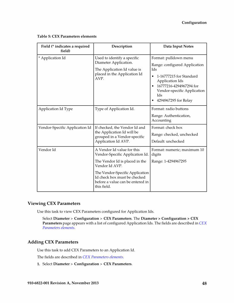
Table 5: CEX Parameters elements
Data Input NotesDescriptionField (* indicates a requiredfield)
Format: pulldown menuUsed to identify a specificDiameter Application.
* Application Id
Range: configured ApplicationIdsThe Application Id value is
placed in the Application IdAVP. • 1-16777215 for Standard
Application Ids• 16777216-4294967294 for
Vendor-specific ApplicationIds
• 4294967295 for Relay
Format: radio buttonsType of Application Id.Application Id Type
Range: Authentication,Accounting
Format: check boxIf checked, the Vendor Id andthe Application Id will be
Vendor-Specific Application Id
Range: checked, uncheckedgrouped in a Vendor-specificApplication Id AVP. Default: unchecked
Format: numeric; maximum 10digits
A Vendor Id value for thisVendor-Specific Application Id.
Vendor Id
Range: 1-4294967295The Vendor Id is placed in theVendor Id AVP.
The Vendor-Specific ApplicationId check box must be checkedbefore a value can be entered inthis field.
Viewing CEX Parameters
Use this task to view CEX Parameters configured for Application Ids.
Select Diameter > Configuration > CEX Parameters. The Diameter > Configuration > CEXParameters page appears with a list of configured Application Ids. The fields are described in CEXParameters elements.
Adding CEX Parameters
Use this task to add CEX Parameters to an Application Id.
The fields are described in CEX Parameters elements.
1. Select Diameter > Configuration > CEX Parameters.
48910-6822-001 Revision A, November 2013
Configuration
The Diameter > Configuration > CEX Parameters page appears.
2. Click Insert.
The Diameter > Configuration > CEX Parameters [Insert] page appears.
3. Select an Application Id from the pulldown menu.4. Set the Application Id Type.5. If appropriate, check the Vendor Specific Application Id check box.6. If you checked Vendor Specific Application Id, specify the Vendor Id.7. Click:
• OK to save the new CEX Parameters and return to the Diameter > Configuration > CEXParameters page.
• Apply to save the new CEX Parameters and remain on this page.• Cancel to return to the Diameter > Configuration > CEX Parameters page without saving any
changes.
If OK or Apply is clicked and any of the following conditions exist, an error message appears:
• Any fields contain a value that is out of the allowed range• The Application Id, Application Id Type, and Vendor Id combination is not unique
Editing CEX Parameters
Use this procedure to change the Application Id Type, Vendor-Specific Id, or Vendor Id for a selectedApplication Id. (The Application Id field cannot be changed.)
The fields are described in CEX Parameters elements.
When the Diameter > Configuration > CEX Parameters [Edit] page opens, the fields are populatedwith the current configured values.
Note: If the selected Application Id is present in a CEX Configuration Set that is a part of an Enabledconnection, the CEX Parameter fields cannot be changed. An error message is displayed.
1. Select Diameter > Configuration > CEX Parameters.
The Diameter > Configuration > CEX Parameters page appears.
2. Select the Application Id row to be changed.3. Click the Edit button.
The Diameter > Configuration > Application Ids [Edit] page appears.
4. Change the Application Id Type, Vendor-Specific Id, or Vendor Id for the selected ApplicationId.The Vendor Id must be unique.
5. Click:
• OK to save the changes and return to the Diameter > Configuration > CEX Parameters page.• Apply to save the changes and remain on this page.• Cancel to return to the Diameter > Configuration > CEX Parameters page without saving any
changes.
49910-6822-001 Revision A, November 2013
Configuration
If OK or Apply is clicked and any of the following conditions exist, an error message appears:
• The selected Application Id no longer exists; it has been deleted by another user• Any fields contain values that are out of range• Any required field is empty (not entered)• The Application Id, Application Id Type, and Vendor Id combination is not unique
Deleting CEX Parameters
Use the following procedure to delete CEX Parameters associated with an Application Id.
Note: CEX Parameters cannot be deleted if the Application Id is associated with a CEX ConfigurationSet.
1. Select Diameter > Configuration > CEX Parameters.
The Diameter > Configuration > CEX Parameters page appears.
2. Select the Application Id for which you want to delete CEX Parameters.3. Click the Delete button.
A popup window appears to confirm the delete.
4. Click:
• OK to delete the CEX Parameters from the Application Id.
If the Application Id is associated with a CEX Configuration Set, the CEX Parameters are notdeleted and an error message appears.
• Click Cancel to cancel the delete function and return to the Diameter > Configuration > CEXParameters page.
If OK is clicked and the selected Application Id no longer exists (it was deleted by another user),an error message is displayed and the CEX Parameters view is refreshed.
Command Codes configuration
The Command Code is one of the parameters contained in a Diameter Message. In the CommandCodes configuration section, you can define the Command Code values that can be used in PeerRouting Rules and Application Routing Rules.
On the Diameter > Configuration > Command Codes page, you can perform the following actions:
• Filter the list of Command Codes, to display only the desired Command Codes.
• Sort the list entries in ascending or descending order by Command Code or Command Code Nameby clicking the column heading. By default, the list is sorted by Command Code in ascendingnumerical order.
• Click the Insert button.
50910-6822-001 Revision A, November 2013
Configuration

The Diameter > Configuration > Command Codes [Insert] page opens. You can add a newCommand Code. See Adding a Command Code. If the maximum number of Command Codes (1000)already exists in the system, the Diameter > Configuration > Command Codes [Insert] page willnot open, and an error message is displayed.
• Select an Command Code in the list, and click the Edit button.
The Diameter > Configuration > Command Codes [Edit] page opens. You can edit the selectedCommand Code. See Editing a Command Code.
• Select an Command Code in the list, and click the Delete button to remove the selected CommandCode. See Deleting a Command Code.
Command Codes elements
Table 6: Command Codes elements describes the fields on the Command Codes View, Insert, and Editpages. Data Input Notes apply only to the Insert and Edit pages; the View page is read-only.
Table 6: Command Codes elements
Data Input NotesDescriptionField (* indicates arequired field)
Format: case-sensitive;alphanumeric and underscore (_);
Command Code Name* Name
cannot start with a digit and mustcontain at least one alpha
Range: 1 - 32 characters
Format: Pulldown menu ornumeric
Identifies the command associated withthe message
* Command Code
Range: Select from predefinedCommand Codes or enter anumeric value: 0-16777215
Default: none
Viewing Command Codes
Use this task to view all configured Command Codes.
Select Diameter > Configuration > Command Codes.The Diameter > Configuration > Command Codes page appears with a list of configured CommandCodes. The fields are described in Command Codes elements.
Adding a Command Code
Use this task to configure a new Command Code.
51910-6822-001 Revision A, November 2013
Configuration

The fields are described in Command Codes elements.
1. Select Diameter > Configuration > Command Codes.
The Diameter > Configuration > Command Codes page appears.
2. Click Insert.
The Diameter > Configuration > Command Codes [Insert] page appears.
If the maximum number of Command Codes (1000) has already been configured in the system,the Diameter > Configuration > Command Codes [Insert] page will not open, and an errormessage will appear.
3. Enter a unique Command Code Name for the Command Code.4. Select a Command Code from the menu or enter a unique value to identify a specific Command
Code (Command Code is required.)5. Click:
• OK to save the new Command Code and return to the Diameter > Configuration > CommandCodes page.
• Apply to save the new Command Code and remain on this page.• Cancel to return to the Diameter > Configuration > Command Codes page without saving
any changes.
If OK or Apply is clicked and any of the following conditions exist, an error message appears:
• Any fields contain a value that is out of the allowed range• Any required field is empty (not entered)• Adding the new Command Code would cause the maximum number of Command Codes
(1000) to be exceeded
Editing a Command Code
Use this procedure to change the Command Code Name for a selected Command Code. (The CommandCode field cannot be changed.)
The fields are described in Command Codes elements.
When the Diameter > Configuration > Command Codes [Edit] page opens, the fields are populatedwith the current configured values.
1. Select Diameter > Configuration > Command Codes.
The Diameter > Configuration > Command Codes page appears.
2. Select the Command Code row to be changed.3. Click the Edit button.
The Diameter > Configuration > Command Codes [Edit] page appears.
4. Change the Command Code Name for the selected Command Code.The Name must be unique.
5. Click:
52910-6822-001 Revision A, November 2013
Configuration

• OK to save the changes and return to the Diameter > Configuration > Command Codes page.• Apply to save the changes and remain on this page.• Cancel to return to the Diameter > Configuration > Command Codes page without saving
any changes.
If OK or Apply is clicked and any of the following conditions exist, an error message appears:
• The selected Command Code no longer exists; it has been deleted by another user• Any fields contain values that are out of range• Any required field is empty (not entered)
Deleting a Command Code
Use the following procedure to delete a Command Code.
A Command Code cannot be deleted if it is associated with any of the following Configurationcomponents:
• Peer Routing Rule• Application Routing Rule• Message Priority Configuration Set• A FABR or RBAR Address Resolution
1. Select Diameter > Configuration > Command Codes.
The Diameter > Configuration > Command Codes page appears.
2. Select the Command Code to be deleted.3. Click the Delete button.
A popup window appears to confirm the delete.
4. Click:
• OK to delete the Command Code.
If the Command Code is used in a Peer Routing Rule or Application Routing Rule, the CommandCode is not deleted and an error message appears.
• Click Cancel to cancel the delete function and return to the Diameter > Configuration >Command Codes page.
If OK is clicked and any of the following conditions exist, the selected Command Code no longerexists (it was deleted by another user), an error message is displayed and the Command Codes isrefreshed.
MCC Ranges configuration
The Reserved MCC Ranges component defines up to 10 distinct, non-overlapping Mobile CountryCode Ranges, which are the first 3 digits of the IMSI. A decoded IMSI that falls within one of theseMCC ranges is considered reserved for Address Resolution in the Range Based Address Resolution
53910-6822-001 Revision A, November 2013
Configuration

(RBAR) and Full Address Based Resolution (FABR) DSR Application. RBAR and FABR will continuedecoding using other AVP instances, or next Priority AVP (if configured), or next Routing Entity (ifconfigured).
The two following MCC Ranges are reserved by telephony standards and are recommended to beconfigured in addition to other user-specified ranges:
• 000-199• 800-899
On the Diameter > Configuration > MCC Ranges page, you can perform the following actions:
• Filter the list of MCC Ranges, to display only the desired MCC Ranges.
• Sort the list entries in ascending or descending order by Start MCC range or End MCC range byclicking the column heading. By default, the list is sorted by Start MCC range in ascending ASCIIorder.
• Click the Insert button.
The Diameter > Configuration > MCC Ranges [Insert] page opens. You can add new MCC Ranges.If the maximum number of MCC Ranges (10) already exists in the system, the Diameter >Configuration > MCC Ranges [Insert] page will not open, and an error message is displayed.
• Select an MCC Range in the list, and click the Edit button.
The Diameter > Configuration > MCC Ranges [Edit] page opens. The selected Start MCC, EndMCC, or both for the selected MCC Range can be edited.
• Select an MCC Range in the list, and click the Delete button to remove the selected MCC Range.
MCC Ranges elements
Table 7: MCC Ranges elements describes the fields on the Diameter > Configuration > MCC Rangespages.
Table 7: MCC Ranges elements
ValueDescriptionField (* indicates arequired field)
Format: text box; numeric.The start value of the Reserved MobileCountry Code Range.
* Start MCC
Range: 0-999
Format: text box; numeric.The end value of the Reserved MobileCountry Code Range.
* End MCC
Range: 0-999
Viewing MCC Ranges
Use this task to view all configured MCC Ranges.
MCC Ranges fields are described in MCC Ranges elements.
54910-6822-001 Revision A, November 2013
Configuration
Select Diameter > Configuration > MCC Ranges.The Diameter > Configuration > MCC Ranges page appears with a list of configured MCC Ranges.
Adding MCC Ranges
Use this task to configure new MCC Ranges.
MCC Ranges fields are described in MCC Ranges elements.
1. Select Diameter > Configuration > MCC Ranges.
The Diameter > Configuration > MCC Ranges page appears.
2. Click Insert.
The Diameter > Configuration > MCC Ranges [Insert] page appears.
If the maximum number of MCC Ranges (10) has already been configured in the system, theDiameter > Configuration > MCC Ranges [Insert] page will not open, and an error message willappear.
3. Enter a value for the Start MCC field.4. Enter a value for the End MCC field.5. Click:
• OK to save the new MCC Range and return to the Diameter > Configuration > MCC Rangespage.
• Apply to save the new MCC Range and remain on this page. The data displayed on the pageis updated.
• Cancel to return to the Diameter > Configuration > MCC Ranges page without saving anychanges.
If OK or Apply is clicked and any of the following conditions exist, an error message appears:
• Any fields contain a value that is out of the allowed range• Any required field is empty (not entered)• Adding the new MCC Range would cause the maximum number of MCC Ranges (10) to be
exceeded• The Start MCC field value is greater than the End MCC field value• The MCC Range created lies within the ranges of other MCC Ranges
Editing MCC Ranges
Use this task to change MCC Ranges.
MCC Ranges fields are described in MCC Ranges elements.
When the Diameter > Configuration > MCC Ranges [Edit] page opens, the fields are populated withthe current configured values.
1. Select Diameter > Configuration > MCC Ranges.
The Diameter > Configuration > MCC Ranges page appears.
55910-6822-001 Revision A, November 2013
Configuration

2. Select the MCC Range to be changed.3. Click the Edit button.
The Diameter > Configuration > MCC Ranges [Edit] page appears.
4. Change the Start MCC and End MCC fields.
5. Click:
• OK to save the changes and return to the Diameter > Configuration > MCC Ranges page.• Apply to save the changes and remain on this page.• Cancel to return to the Diameter > Configuration > MCC Ranges page without saving any
changes.
If OK or Apply is clicked and any of the following conditions exist, an error message appears:
• The selected MCC Range no longer exists; it has been deleted by another user• Any field contains values that are out of range• Any required field is empty (not entered)• The Start MCC field value is greater than the End MCC field value• The MCC Range created lies within the ranges of other MCC Ranges
Deleting MCC Ranges
Use this tak to delete a MCC Ranges.
1. Select Diameter > Configuration > MCC Ranges.
The Diameter > Configuration > MCC Ranges page appears.
2. Select the MCC Range to be deleted.3. Click the Delete button.
A popup window appears to confirm the delete.
4. Click:
• OK to delete the MCC Ranges.
• Click Cancel to cancel the delete function and return to the Diameter > Configuration > MCCRanges page.
If OK is clicked and the selected MCC Range no longer exists (it was deleted by another user), anerror message is displayed.
Connection Configuration Set configuration
Connection Configuration Sets provide a mechanism for adjusting a connection to account for thenetwork quality of service and Peer Node requirements. You can create a Connection ConfigurationSet with specific SCTP, Diameter, and TCP options and then assign it to a connection. The options are
56910-6822-001 Revision A, November 2013
Configuration

described in Connection Configuration Set elements. Each connection references a single ConnectionConfiguration Set.
The application has a default Connection Configuration Set called Default. The Default ConnectionConfiguration Set options can be modified, but the Default Connection Configuration Set cannot bedeleted. When you create a new Connection Configuration Set the values of the Default ConnectionConfiguration Set are automatically populated into the new Connection Configuration Set, allowingyou to easily create a new Connection Configuration Set that needs to have only a few options adjusted.
On the Connection Configuration Sets page, you can perform the following actions:
• Filter the list of Connection Configuration Sets to display only the desired Connection ConfigurationSets.
• Sort the list by column contents in ascending or descending order, by clicking the column heading.The default order is by Connection Configuration Set Name in ascending ASCII order.
• Click a tab to display the options for the Connection Configuration Set on that tab. The ConnectionConfiguration Set Name remains on the left of the page when the page is scrolled to the right tosee all of the options.
• Click the Insert button.
The Connection Configuration Sets [Insert] page appears. You can add a new ConnectionConfiguration Set and its options. See Adding a Connection Configuration Set.
If the maximum number of Connection Configuration Sets per Network Element (2000) alreadyexist in the system, the Connection Configuration Sets [Insert] page will not open, and an errormessage is displayed.
• Select a Connection Configuration Set Name in the list, and click the Edit button.
The Connection Configuration Sets [Edit] page opens. You can edit the selected ConnectionConfiguration Set. See Editing a Connection Configuration Set.
If at least one connection that uses the Connection Configuration Set is in the "Enabled" Adminstate, the Connection Configuration Sets [Edit] page will not open.
• Select a Connection Configuration Set Name in the list, and click the Delete button to remove theselected Connection Configuration Set.
The Default Connection Configuration Set cannot be deleted. See Deleting a Connection ConfigurationSet.
Connection Configuration Set elements
Table 8: Connection Configuration Sets Elements describes the fields on the Connection ConfigurationSets View, Edit, and Insert pages. Data Input Notes apply only to the Insert and Edit pages; the Viewpage is read-only.
Table 8: Connection Configuration Sets Elements
Data Input NotesDescriptionField (* indicatesrequired field)
Format: case-sensitivestring: alphanumeric
Unique Name of the Connection ConfigurationSet.
* ConnectionConfiguration Set Name
57910-6822-001 Revision A, November 2013
Configuration

Data Input NotesDescriptionField (* indicatesrequired field)
and underscore (_);must contain at leastone alpha and cannotstart with a digit
Range: 1 - 32 characters
SCTP Options
Format: numeric;milliseconds
Expected average network round-trip time inmilliseconds. This is used to initialize the
* Retransmit InitialTimeout (ms)
round-trip time value when an association is Range: 10 - 5000started but the round-trip time has not yet beenmeasured. The round-trip time is used by SCTPin calculating when to retransmit chunks.
Default: 120
Format: numeric;milliseconds
Minimum amount of time to wait for anacknowledgment for a message sent. This value
* Retransmit MinimumTimeout (ms)
prevents the retransmit timeout from becoming Range: 10 - 5000too small in networks with a very short round-triptime. Default: 120
Format: numeric;milliseconds
Maximum amount of time to wait for anacknowledgment for a message sent.
* Retransmit MaximumTimeout (ms)
Range: 10 - 10000This value places an upper bound on theexponential back-off algorithm used by SCTP for Default: 120retransmission timing. After this retransmitinterval is reached, retransmits will be sent at aconstant rate until an ACK is received or themaximum attempts is reached.
Format: numeric;milliseconds
Maximum amount of time to wait for an INIT tobe acknowledged.
* Retransmit MaximumTimeout for INIT
Range: 0, 10 - 10000This value overrides the Retransmit MaximumTimeout for INITs and is used to bound the initialsetup time. Default: 120
A value of 0 indicates that the RetransmitMaximum Timeout will be used for INITs as well.
Format: numeric;number of retransmits
Number of consecutive unsuccessful retransmitsthat will cause a path of the SCTP association tobe marked as failed.
* Number ofRetransmits TriggeringPath Failure Range: 1 - 10
This value indicates how many SCTPretransmission attempts should be made to each Default: 3
destination of an SCTP association before markingthe destination as failed.
This value must be less than the Number ofRetransmits Triggering Association Failure value.
58910-6822-001 Revision A, November 2013
Configuration

Data Input NotesDescriptionField (* indicatesrequired field)
Format: numeric;number of attempts
Number of consecutive retransmits that will causean SCTP association to be marked as failed. This
* Number ofRetransmits TriggeringAssociation Failure Range: 1 - 20value indicates how many SCTP retransmission
attempts should be made to all destinations foran SCTP association before marking theassociation as failed.
Default: 5
This value should not be greater than the sum ofthe retransmit attempts for all destinations withinthe association.
Format: numeric;number of attempts
Number of consecutive retransmits for INIT andCOOKIE-ECHO Chunks that will cause an SCTP
* Number ofRetransmits TriggeringInit Failure Range: 1 - 20connection to be marked as failed. This value
indicates how many retransmission attemptsshould be made to the primary SCTP address for Default: 8INIT and COOKIE-ECHO Chunks before markingthe connection as failed.
Format: numeric;milliseconds
The number of milliseconds to delay afterreceiving a DATA Chunk and prior to sending aSACK.
* SACK Delay
Range: 0 - 200A non-zero value for SACK Delay gives theapplication time to bundle DATA Chunks in the Default: 10
same SCTP datagram with the SACK, therebyreducing the number of packets in the network.Setting SACK Delay to zero disables this delay sothat SACKs are sent as quickly as possible.
Format: numeric;milliseconds
The number of milliseconds between sendingSCTP HEARTBEAT messages to a Peer.
* SCTP HeartbeatInterval
Range: 0, 100 - 300000Heartbeat messages are sent only when no userdata has been sent for the duration of theHeartbeat Interval. Default: 500
Setting the Heartbeat Interval to 0 disablesheartbeating (not recommended).
Format: numeric;number of bytes
Socket send buffer size for outgoing SCTPmessages.
* Socket Send BufferSize (bytes)
Range: 8000 - 5000000The send buffer size must be greater than or equalto the product of the bandwidth and the roundtrip delay for the association. Default: 2000000
Format: numeric;number of bytes
Socket receive buffer size for incoming SCTPmessages.
* Socket Receive BufferSize (bytes)
Range: 8000 - 5000000
59910-6822-001 Revision A, November 2013
Configuration

Data Input NotesDescriptionField (* indicatesrequired field)
The receive buffer size must be greater than orequal to the product of the bandwidth and theround trip delay for the association.
Default: 2000000
Format: numericSpecifies the maximum burst of packets that canbe emitted by this association.
* Maximum Burst
Range: 1 - 4
Default: 4
Format: numeric;number of streams
Maximum number of inbound SCTP streamssupported locally by the SCTP connection.
* Max Number ofInbound Streams
Range: 1 -16
Default: 8
Format: numeric;number of streams
Maximum number of outbound SCTP streamssupported locally by the SCTP connection.
* Max Number ofOutbound Streams
Range: 1 -16
Default: 8
Format: check box
Range: checked (YES) orunchecked (NO)
If checked, datagram bundling is enabled for theSCTP connection.
Datagram BundlingEnabled
Default: checked
Diameter Options
Format: numeric;seconds
Controls the frequency that transport connectionattempts are done to a Peer where no activetransport connection exists.
* Connect Timer (sec)
Range: 5 - 60Applicable only for connections that areconfigured to initiate a connection with a PeerNode.
Default: 30
Format: numeric;seconds
Initial value of the application watchdog timer.* Watchdog Timer InitValue (sec)
Range: 1 - 30
Default: 30
Format: numeric;seconds
Time to wait on a CER message from a Peer aftera connection is initiated by the Peer. Time to wait
* Capabilities ExchangeTimer (sec)
on a CEA response from a Peer after sending theCER. Range: 1 - 10
Default: 3
Format: numeric;seconds
After sending a DPA message, time to wait for aPeer to disconnect transport. After sending a DPR
* Disconnect Timer (sec)
60910-6822-001 Revision A, November 2013
Configuration

Data Input NotesDescriptionField (* indicatesrequired field)
Range: 1 - 10message, time to wait for the Peer to send theDPA. Default: 3If the timer expires, transport will be disconnectedby the application.
Format: radio buttonsProving mode for the Configuration Set.Proving Mode
Range: Suspect, Always,Never
Default: Suspect
Format: numeric;milliseconds
The time to wait for a Peer to send a DWAmessage in response to a DWR message duringconnection proving.
* Proving Timer (msec)
Range: 50 - 30000
Default: 500
Format: numeric;number of exchanges
The number of consecutive DWR and DWAexchanges within Proving Timer time duringconnection proving.
* Proving Times
Range: 1 - 1000
Default: 3
Format: numericThe maximum number of Pending Requestswaiting for Answers from the Peer on this
* Pending TransactionsPer Connection Range: 1 - 20000connection. If the maximum is reached, this
connection will not be selected for routing until Default: 1000the number of Pending Requests falls below thisvalue.
TCP Options
Format: check boxIf checked, the Nagle algorithm is enabled for theTCP connection.
Nagle Enabled
Range: checked (YES),unchecked (NO)
Default: checked
Format: numeric; bytesSocket send buffer size for outgoing TCPmessages. The send buffer size should be greater
* Socket Send BufferSize (bytes) Range: 8000 - 5000000than or equal to the product of the bandwidth and
the round trip delay for the connection. Default: 2000000
Format: numeric; bytesSocket receive buffer size for incoming TCPmessages. The receive buffer size should be
* Socket Receive BufferSize (bytes) Range: 8000 - 5000000greater than or equal to the product of the
bandwidth and the round trip delay for theconnection.
Default: 2000000
61910-6822-001 Revision A, November 2013
Configuration

Viewing Connection Configuration Sets
Use this task to view currently configured Connection Configuration Sets.
Select Diameter > Configuration > Configuration Sets > Connection Configuration Sets.The Connection Configuration Sets page appears.
Adding a Connection Configuration Set
Use this task to create a new Connection Configuration Set.
When you add a new Connection Configuration Set all of the fields on each tab are initially populatedwith the values from the Default Connection Configuration Set. For details about the fields in theConnection Configuration Set, see Connection Configuration Set elements.
1. Select Diameter > Configuration > Configuration Sets > Connection Configuration Sets.The Connection Configuration Sets page appears.
2. Click Insert.The Connection Configuration Sets [Insert] page appears.
3. Enter a unique name for the Configuration Set in the Connection Configuration Set Name field.4. Click the SCTP Options tab. Enter the SCTP values in the fields.5. Click the Diameter Options tab. Enter the Diameter values in the fields.6. Click the TCP Options tab. Enter the TCP values in the fields.7. Click:
• OK to save the data and return to the Connection Configuration Sets page.• Apply to save the data and remain on this page.• Cancel to return to the Connection Configuration Sets page without saving any changes.
If OK or Apply is clicked and any of the following conditions exist, an error message appears:
• Any field is empty (no value was entered)• The value in any field is not valid or is out of range• The Connection Configuration Set Name is not unique; it already exists in the system• The maximum number of Connection Configuration Sets per Network Element (2000) is already
configured• Under the SCTP Options tab, the Retransmit Maximum Timeout is less than the Retransmit
Minimum Timeout• Under the SCTP Options tab, the Number of Retransmits Triggering Path Failure is greater
than the Number of Retransmits Triggering Association Failure
Editing a Connection Configuration Set
Use this task to edit an existing Connection Configuration Set.
When the Connection Configuration Sets page opens, the fields are populated with the currentlyconfigured values.
62910-6822-001 Revision A, November 2013
Configuration

If the selected Connection Configuration Set is being used by a Local Node, any changes to the selectedConnection Configuration Set will not take effect for Peer-initiated connections until the next time thePeer Node connects to the Local Node.
The Connection Configuration Set Name cannot be edited.
Note: You must disable all Connections that use a particular Connection Configuration Set beforeyou can edit it. See Disabling Connections.
Changes to the Connection Configuration Set take effect after the changes are saved and the Connectionsthat refer to the changed Connection Configuration Set are set to the "Enabled" Admin state.
1. Select Diameter > Configuration > Configuration Sets > Connection Configuration Sets.The Connection Configuration Sets page appears.
2. Select the Connection Configuration Set you want to edit.3. Click Edit.
The Connection Configuration Sets [Edit] page appears.4. Update the relevant fields.
For information about each field, see Connection Configuration Set elements.
5. Click:
• OK to save the data and return to the Connection Configuration Sets page.• Apply to save the data and remain on this page.• Cancel to return to the Connection Configuration Sets page without saving any changes.
If OK or Apply is clicked and any of the following conditions exist, an error message appears:
• The selected Connection Configuration Set no longer exists; it has been deleted by another user• Any field is empty (no value was entered)• The value in any field is not valid or is out of range• Under the SCTP Options tab, the Retransmit Maximum Timeout is less than the Retransmit
Minimum Timeout• Under the SCTP Options tab, the Number of Retransmits Triggering Path Failure is greater
than the Number of Retransmits Triggering Association Failure• At least one connection that is using this Connection Configuration Set is not in the "Disabled"
Admin State
Deleting a Connection Configuration Set
Use this task to delete a Connection Configuration Set.
A Connection Configuration Set cannot be deleted if it is being used by any connections or LocalNodes. Before you perform this task, you must:
1. Disable any connections that use the Connection Configuration Set. See Disabling Connections.2. Edit those connections to no longer use the Connection Configuration Set. See Editing a Connection.3. Edit any Local Nodes that use the Connection Configuration Set to no longer do so. See Editing a
Local Node.
1. Select Diameter > Configuration > Configuration Sets > Connection Configuration Sets.The Connection Configuration Sets page appears.
2. Select the Connection Configuration Set you want to delete.
63910-6822-001 Revision A, November 2013
Configuration
3. Click Delete.A popup window appears to confirm the delete.
4. Click:
• OK to delete the Connection Configuration Set.• Cancel to cancel the delete function and return to the Connection Configuration Sets page.
If OK is clicked and the selected Connection Configuration Set is referenced by at least oneconnection or Local Node, an error message appears and the Connection Configuration Set is notdeleted.
If OK is clicked and the selected Connection Configuration Set no longer exists (it was deleted byanother user), an error message is displayed and the Connection Configuration Sets view is refreshed.
CEX Configuration Set configuration
A CEX Configuration Set provides a mechanism for assigning up to 10 unique CEX Parameters andup to 10 unique supported Vendor IDs to a Local Node or Connection. A default CEX ConfigurationSet named “Default” is pre-populated with CEX Parameters for the “RELAY” Application Id (0xFFFFFFFF).
Each Local Node will refer to a single CEX Configuration Set. The CEX Configuration Set is mandatoryfor Local Node. Each transport connection can optionally refer to a single CEX Configuration Set.During CEx message exchange, the CEX Configuration Set in the transport connection is used ifconfigured. Otherwise, the CEX Configuration Set in the Local Node (associated with the transportconnection) is used. A Vendor Id can be sent in the Supported-Vendor-ID AVP of a CEx even thoughthe Vendor Id is not configured in the Selected Supported Vendor Ids for the CEX Configuration Set.
The application has a default CEX Configuration Set called Default, which is always available. TheDefault CEX Configuration Set options cannot be modified or deleted. When you create a new CEXConfiguration Set the values of the Default CEX Configuration Set are automatically populated intothe new CEX Configuration Set, allowing you to easily create a new CEX Configuration Set that needsto have only a few options adjusted.
On the CEX Configuration Sets page, you can perform the following actions:
• Filter the list of CEX Configuration Sets to display only the desired CEX Configuration Sets.
• Sort the list in ascending or descending order, by clicking the CEX Configurations Set Namecolumn heading. The default order is by CEX Configuration Set Name in ascending ASCII order.
• In the CEX Parameters column,
• Click the + sign to the left of the number of Application Ids to expand the list of ApplicationIds for a CEX Configuration Set.
• Click the - sign to left of the number of Application Ids to collapse the expanded list ofApplication Ids for a CEX Configuration Set.
• Click a blue Application Id in an expanded list to open the Diameter > Configuration > CEXParameters [Filtered] page for the selected Application Id only.
• Click the Insert button.
The CEX Configuration Sets [Insert] page opens. You can add a new CEX Configuration Set andits values. See Adding a CEX Configuration Set. If the maximum number of CEX Configuration Sets
64910-6822-001 Revision A, November 2013
Configuration

(2000) already exists in the system, the CEX Configuration Sets [Insert] page will not open, andan error message is displayed.
• Select a CEX Configuration Set Name in the list, and click the Edit button.
The CEX Configuration Sets [Edit] page opens. You can edit the selected CEX Configuration Set.See Editing a CEX Configuration Set. The Default CEX Configuration Set cannot be edited.
• Select a CEX Configuration Set Name in the list, and click the Delete button to remove the selectedCEX Configuration Set.
The Default CEX Configuration Set cannot be deleted. See Deleting a CEX Configuration Set.
CEX Configuration Set elements
Table 9: Configuration Sets Elements describes the fields on the CEX Configuration Sets View, Edit, andInsert pages. Data Input Notes only apply to the Insert and Edit pages; the View page is read-only.
Table 9: Configuration Sets Elements
Data Input NotesDescriptionField (* indicates arequired field)
Format: Case-sensitivestring: alphanumeric
Unique Name of the CEX Configuration Set.
A CEX Configuration Set named Default is alwaysavailable.
* CEX Configuration SetName
and underscore (_);must contain at leastone alpha and cannotbegin with a digit.
Range: 1 - 32 characters
Format: Scrollable listAvailable CEX Parameters
All unique configured CEX Parameters, showingApplication Ids with Application Type, and withVendor Id if the Application Id is Vendor-Specific.
* CEX Parameters
Range: All configuredCEX Parameters
Maximum of 10 entries.Selected CEX Parameters
CEX Parameters that are selected from theAvailable CEX Parameters list for this CEXConfiguration Set.
Default: Relay
One, some, or all of theentries in the Selected
Must Include CEX Parameters
CEX Parameters selected from the Selected CEXParameters list that must be present in the CExmessage exchanged from the Peer.
CEX Parameters list;maximum of 10 entries
Format: Scrollable listAvailable Supported Vendor Ids
All unique Vendor Ids that have been configuredin the CEX Parameters configuration.
Supported Vendor Ids
Range: All configuredVendor Ids
65910-6822-001 Revision A, November 2013
Configuration
Data Input NotesDescriptionField (* indicates arequired field)
Maximum of 10 entriesSelected Supported Vendor Ids
Application Ids that are selected from theAvailable Supported Vendor Ids list for this CEXConfiguration Set.
Viewing CEX Configuration Sets
Use this task to view currently configured CEX Configuration Sets.
Select Diameter > Configuration > Configuration Sets > CEX Configuration Sets.The CEX Configuration Sets page appears.
Adding a CEX Configuration Set
Use this task to create a new CEX Configuration Set.
1. Select Diameter > Configuration > Configuration Sets > CEX Configuration Sets.The CEX Configuration Sets page appears.
2. Click Insert.The CEX Configuration Sets [Insert] page appears.
3. Enter a unique name for the CEX Configuration Set in the CEX Configuration Set Name field.4. Enter the information for the CEX Parameters in the fields.
• To add CEX Parameters to the Selected CEX Parameters list, select the entry in the AvailableCEX Parameters list and click the Add button below the Available CEX Parameters list.
• To add CEX Parameters to the Must Include CEX Parameters list, select the entry in the SelectedCEX Parameters list and click the Add button above the Must Include CEX Parameters list.
• To remove CEX Parameters from the Selected CEX Parameters list, select the entry in theSelected CEX Parameters list and click the Remove button below the Selected CEX Parameterslist.
• To remove CEX Parameters from the Must Include CEX Parameters list, select the entry in theMust Include CEX Parameters list and click the Remove button above the Must Include CEXParameters list.
5. Enter the information for the Supported Vendor IDs in the fields.
• To add a Vendor Id to the Selected Supported Vendor Ids list, select the entry in the AvailableSupported Vendor Ids list and click the Add button below the Available Supported VendorIds list.
• To remove a Vendor Id from the Selected Supported Vendor Ids list, select the entry in theSelected Supported Vendor Ids list and click the Remove button above the Selected SupportedVendor Ids list.
6. Click:
• OK to save the new CEX Configuration Set and return to the CEX Configuration Sets page.• Apply to save the new CEX Configuration Set and remain on this page.
66910-6822-001 Revision A, November 2013
Configuration

• Cancel to return to the CEX Configuration Sets page without saving any changes.
If OK or Apply is clicked and any of the following conditions exist, an error message appears:
• The Selected CEX Parameters list is empty (an item was not added)• Any item that was selected to add to a list was deleted by another user during this Insert session• The maximum number of configured CEX Configuration Sets (2000), Selected CEX Parameters
+ Must Include CEX Parameters for a CEX Configuration Set (10), or Supported Vendor Ids fora CEX Configuration Set (10) was reached by another user's entries during this Insert session
Editing a CEX Configuration Set
Use this task to edit an existing CEX Configuration Set.
For information about each field, see CEX Configuration Set elements.
Note: You must disable connections that use a particular CEX Configuration Set before you can editthe CEX Configuration Set. See Disabling Connections.
1. Select Diameter > Configuration > Configuration Sets > CEX Configuration Sets.The CEX Configuration Sets page appears.
2. Select the CEX Configuration Set that you want to edit.The Default CEX Configuration Set cannot be changed.
3. Click Edit.
The CEX Configuration Sets [Edit] page appears.
When the page opens, the fields are initially populated with the currently configured values.
4. Update the relevant fields.
If an entry is attempted that is not valid or is out of range, an error message appears.
The CEX Configuration Set Name cannot be changed.
• To add CEX Parameters to the Selected CEX Parameters list, select the entry in the AvailableCEX Parameters list and click the Add button below the Available CEX Parameters list.
• To add CEX Parameters to the Must Include CEX Parameters list, select the entry in the SelectedCEX Parameters list and click the Add button above the Must Include CEX Parameters list.
• To remove CEX Parameters from the Selected CEX Parameters list, select the entry in theSelected CEX Parameters list and click the Remove button below the Selected CEX Parameterslist.
• To remove CEX Parameters from the Must Include CEX Parameters list, select the entry in theMust Include CEX Parameters list and click the Add button above the Must Include CEXParameters list.
• To add a Vendor Id to the Selected Supported Vendor Ids list, select the entry in the AvailableSupported Vendor Ids list and click the Add button below the Available Supported VendorIds list.
• To remove a Vendor Id from the Selected Supported Vendor Ids list, select the entry in theSelected Supported Vendor Ids list and click the Remove button above the Selected SupportedVendor Ids list.
5. Click:
67910-6822-001 Revision A, November 2013
Configuration

• OK to save the changes and return to the CEX Configuration Sets page.• Apply to save the changes and remain on this page.• Cancel to return to the CEX Configuration Sets page without saving any changes.
If OK or Apply is clicked and any of the following conditions exist, an error message appears:
• The Selected CEX Parameters list is empty (no items were added)• Any item that was selected to add to a list was deleted by another user during this Insert session• The selected CEX Configuration Set is being used by a connection or a Local Node• The selected CEX Configuration Set was deleted by another user during this Edit session
Deleting a CEX Configuration Set
Use this task to delete a CEX Configuration Set.
A CEX Configuration Set cannot be deleted if it is being used by any connections or Local Nodes.Before you perform this task, you must:
1. Disable any connections that use the CEX Configuration Set. See Disabling Connections.2. Edit those connections to no longer use the CEX Configuration Set. See Editing a Connection.3. Edit any Local Nodes that use the CEX Configuration Set to no longer do so. See Editing a Local
Node.
The Default CEX Configuration Set can be edited, but cannot be deleted.
1. Select Diameter > Configuration > Configuration Sets > CEX Configuration Sets.The CEX Configuration Sets page appears.
2. Select one CEX Configuration Set that you want to delete.3. Click Delete
A popup window appears.4. Click:
• OK to delete the selected CEX Configuration Set.• Cancel to cancel the delete function and return to the CEX Configuration Sets page.
If OK is clicked and the selected CEX Configuration Set is referenced by at least one connection orLocal Node, an error message appears and the CEX Configuration Set is not deleted.
If OK is clicked and the selected CEX Configuration Set no longer exists (it was deleted by anotheruser), an error message is displayed and the CEX Configuration Sets view is refreshed.
Capacity Configuration Set configuration
Capacity Configuration Sets provide a mechanism for adjusting a connection to account for the networkquality of service and Peer Node requirements, and allow management of capacity data for DiameterPeer connections. Capacity Configuration Set data consists of reserved Ingress MPS, maximum IngressMPS, Ingress MPS minor alarm threshold, and Ingress MPS major alarm threshold.
The Capacity Configuration Set called Default is always available. The Default Capacity ConfigurationSet options can be modified, but the Default Capacity Configuration Set cannot be deleted. When you
68910-6822-001 Revision A, November 2013
Configuration

create a new Capacity Configuration Set the values of the Default Capacity Configuration Set areautomatically populated into the new Capacity Configuration Set, allowing you to easily create a newCapacity Configuration Set that needs to have only a few options adjusted.
On the Capacity Configuration Sets page, you can perform the following actions:
• Filter the list of Capacity Configuration Sets to display only the desired Capacity ConfigurationSets.
• Sort the Capacity Configuration Set entries by clicking the column headings. By default, the entriesare sorted by the Capacity Configuration Set column in ascending ASCII order.
• Click the Insert button.
The Capacity Configuration Sets [Insert] page opens. You can add a new Capacity ConfigurationSets and its values. See Adding a Capacity Configuration Set.
If the maximum number of Capacity Configuration Sets (1000) already exists in the system, theCapacity Configuration Sets [Insert] page does not open and an error message is displayed.
• Select the Name of a Capacity Configuration Set in the list, and click the Edit button.
The Capacity Configuration Sets [Edit] page opens. You can edit the selected CapacityConfiguration Set. See Editing a Capacity Configuration Set.
• Select the Name of a Capacity Configuration Set in the list, and click the Delete button to removethe selected Capacity Configuration Set. See Deleting a Capacity Configuration Set. The DefaultCapacity Configuration Set can be edited, but not deleted.
Connection Capacity Validation
The Connection Capacity Validation function validates and limits the configuration of DiameterConnections, to better ensure that the configuration does not violate the Connection Count or ReservedIngress MPS capacity limitations of the DA-MP servers that handle Connections in real time.
The Connection Capacity Validation function is described in Connection Capacity Validation.
Validation of the Reserved Ingress MPS occurs in response to changes to the configuration of CapacityConfiguration Sets that increase the Reserved Ingress MPS value, including editing the value andreplacing the Configuration Set with one that has a higher value. Such changes reduce the availableReserved Ingress MPS capacity of a DSR and must be validated before they can be allowed. (Actionsthat increase capacity rather than reduce it do not require validation.)
An error is displayed, stating the reason, when the validation determines that performing theconfiguration action would cause over-configuration of Reserved Ingress MPS in a DA-MP or TargetSet, or that a configuration action cannot be performed for another reason such as no MP Profileassigned to the subject DA-MP.
A warning is displayed when the validation cannot determine whether the configuration action wouldcause over-configuration of Reserved Ingress MPS in a DA-MP or Target Set.
If an error and a warning could apply, the error is displayed.
The Diameter > Configuration > Connection Capacity Dashboard page displays the current ConnectionCount and Reserved Ingress MPS data per DA-MP. The page functions and contents are described inConnection Capacity Dashboard Page.
69910-6822-001 Revision A, November 2013
Configuration
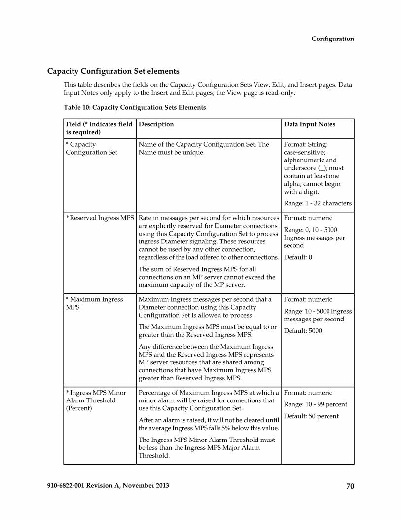
Capacity Configuration Set elements
This table describes the fields on the Capacity Configuration Sets View, Edit, and Insert pages. DataInput Notes only apply to the Insert and Edit pages; the View page is read-only.
Table 10: Capacity Configuration Sets Elements
Data Input NotesDescriptionField (* indicates fieldis required)
Format: String:case-sensitive;
Name of the Capacity Configuration Set. TheName must be unique.
* CapacityConfiguration Set
alphanumeric andunderscore (_); mustcontain at least onealpha; cannot beginwith a digit.
Range: 1 - 32 characters
Format: numericRate in messages per second for which resourcesare explicitly reserved for Diameter connections
* Reserved Ingress MPS
Range: 0, 10 - 5000Ingress messages persecond
using this Capacity Configuration Set to processingress Diameter signaling. These resourcescannot be used by any other connection,regardless of the load offered to other connections. Default: 0
The sum of Reserved Ingress MPS for allconnections on an MP server cannot exceed themaximum capacity of the MP server.
Format: numericMaximum Ingress messages per second that aDiameter connection using this CapacityConfiguration Set is allowed to process.
* Maximum IngressMPS Range: 10 - 5000 Ingress
messages per secondThe Maximum Ingress MPS must be equal to orgreater than the Reserved Ingress MPS. Default: 5000
Any difference between the Maximum IngressMPS and the Reserved Ingress MPS representsMP server resources that are shared amongconnections that have Maximum Ingress MPSgreater than Reserved Ingress MPS.
Format: numericPercentage of Maximum Ingress MPS at which aminor alarm will be raised for connections thatuse this Capacity Configuration Set.
* Ingress MPS MinorAlarm Threshold(Percent) Range: 10 - 99 percent
Default: 50 percentAfter an alarm is raised, it will not be cleared untilthe average Ingress MPS falls 5% below this value.
The Ingress MPS Minor Alarm Threshold mustbe less than the Ingress MPS Major AlarmThreshold.
70910-6822-001 Revision A, November 2013
Configuration

Data Input NotesDescriptionField (* indicates fieldis required)
Format: numericPercentage of Maximum Ingress MPS at which amajor alarm will be raised for connections thatuse this Capacity Configuration Set.
* Ingress Major AlarmThreshold (Percent) Range: 11 - 100 percent
Default: 80 percentAfter an alarm is raised, it will not be cleared untilthe average Ingress MPS falls 5% below this value.
The Ingress MPS Major Alarm Threshold must begrerater than the Ingress MPS Minor AlarmThreshold.
Format: numericTime (in ms) that a DSR Connection's ingressmessage rate must remain less than or equal to
* Reserved Ingress MPSAbatement Time Range: 1000 - 5000 msReserved Ingress MPS, after exceeding Reserved
Ingress MPS, in order to revert the ingress trafficcolor from Yellow to Green.
Default: 2000 ms
Viewing Capacity Configuration Sets
Use this task to view currently configured Capacity Configuration Sets.
Select Diameter > Configuration > Configuration Sets > Capacity Configuration Sets.The Capacity Configuration Sets page appears.
Adding a Capacity Configuration Set
Use this task to create a new Capacity Configuration Set. For information about the fields, see CapacityConfiguration Set elements.
1. Select Diameter > Configuration > Configuration Sets > Capacity Configuration Sets.The Capacity Configuration Sets page appears.
2. Click Insert.The Capacity Configuration Sets [Insert] page appears.
3. Enter a unique name for the Capacity Configuration Set in the Name field.4. Enter the Reserved Ingress MPS value in messages/second.5. Enter the Maximum Ingress MPS value in messages/second.6. Enter the Ingress MPS Minor Alarm Threshold as the percentage of the Maximum Ingress MPS
at which a Minor alarm will be raised for connections using this Capacity Configuration Set.7. Enter the Ingress MPS Major Alarm Threshold as the percentage of the Maximum Ingress MPS
at which a Major alarm will be raised for connections using this Capacity Configuration Set.8. Enter the Reserved Ingress MPS Abatement Time in milliseconds, if a value other than the default
value is needed.9. Click:
• OK to save the changes and return to the Capacity Configuration Sets page.• Apply to save the changes and remain on this page.
71910-6822-001 Revision A, November 2013
Configuration

If OK or Apply is clicked and any of the following conditions exist, an error message appears:
• Any field value is missing (not entered)• The Capacity Configuration Set is not unique (already exists in the system)• The maximum number of Capacity Configuration Sets (1000) is already configured• The Reserved Ingress MPS value is greater than the Maximum Ingress MPS value• The Ingress MPS Minor Alarm Threshold value is greater than the Ingress MPS Major Alarm
Threshold value
Editing a Capacity Configuration Set
Use this task to edit an existing Capacity Configuration Set.
The changes take effect upon receipt of the next message. Ingress MPS alarms are re-evaluated for allConnections that use the modified Capacity Configuration Set when the changes are replicated to theMP servers.
All Connections that use a particular Capacity Configuration Set must be in the Disabled Admin Statebefore the Reserved Ingress MPS value can be changed. See Disabling Connections. (The ReservedIngress MPS field is the only field that requires the Connections to be "Disabled" before it can bechanged.) See Disabling Connections.
The Capacity Configuration Set name cannot be changed.
1. Select Diameter > Configuration > Configuration Sets > Capacity Configuration Sets.The Diameter > Configuration > Configuration Sets > Capacity Configuration Sets page appears.
2. Select the Capacity Configuration Set to be edited.3. Click Edit.
The Capacity Configuration Sets [Edit] page appears.
The Capacity Configuration Sets [Edit] page will be populated with the current values for theselected Capacity Configuration Set.
4. Update the relevant fields.The fields are described in Capacity Configuration Set elements.
5. Click:
• OK to save the changes and return to the Capacity Configuration Sets page.• Apply to save the changes and remain on this page.• Cancel to return to the Capacity Configuration Sets page without saving any changes.
When OK or Apply is clicked, a popup window appears.
• Click OK to confirm that you want to change the Capacity Configuration Set values.• Click Cancel to remain on the Capacity Configuration Sets [Edit] page with the changes
displayed but not saved.
If Apply is clicked on the Capacity Configuration Sets [Edit] page, OK is clicked on the confirmationpopup window, and all changes are valid, a "Data Committed" message appears.
If OK is clicked on the popup window and the Reserved Ingress MPS field was changed for aCapacity Configuration Set that is referenced by any Connection that is in the "Enabled" Adminstate, an error message appears and the changes are not saved.
72910-6822-001 Revision A, November 2013
Configuration

6. Enable any Connections that were Disabled before the Capacity Configuration Set was changed.See Enabling Connections.
Deleting a Capacity Configuration Set
Use this task to delete a Capacity Configuration Set.
A Capacity Configuration Set cannot be deleted if it is being used by any Connections. Before youperform this task, you must disable any Connections that use the Capacity Configuration Set and editeach Connection to no longer use the Capacity Configuration Set. (See Disabling Connections and Editinga Connection.)
The Default Capacity Configuration Set can be edited, but cannot be deleted.
1. Select Diameter > Configuration > Configuration Sets > Capacity Configuration Sets.The Capacity Configuration Sets page appears.
2. Select the Capacity Configuration Set you want to delete.3. Click Delete.
A popup window appears to confirm the delete.4. Click:
• OK to delete the Capacity Configuration Set and return to the Capacity Configuration Setspage.
• Cancel to cancel the delete function and return to the Capacity Configuration Sets page.
If OK is clicked and the selected Capacity Configuration Set is referenced by at least one Connection,an error message appears and the Capacity Configuration Set is not deleted.
Egress Message Throttling Configuration Set configuration
Egress Message Throttling Configuration Sets provide a mechanism for managing egress messagetraffic on a Diameter Connection. You can create an Egress Message Throttling Configuration Set witha maximum allowable Egress Message Rate (EMR) and one to three pairs of EMR Threshold Throttlesand Abatement Throttles.
When the Egress Message Rate on a connection exceeds a Threshold Throttle value, the EMR congestionlevel for the connection is raised. When the Egress Message Rate on a connection falls below anAbatement Threshold, the EMR congestion level is lowered. Specifying a Smoothing Factor andAbatement time allows you to control the transitions between EMR congestion levels. The EMRcongestion level, along with the Egress Transport congestion level and the Remote Busy congestionlevel is used to control traffic on a connection.
The options are described in Egress Message Throttling Configuration Set elements. Each connection canreference a single Egress Message Throttling Configuration Set.
On the Egress Message Throttling Configuration Sets page, you can perform the following actions:
• Filter the list of Egress Message Throttling Configuration Sets to display only the desired EgressMessage Throttling Configuration Sets.
73910-6822-001 Revision A, November 2013
Configuration
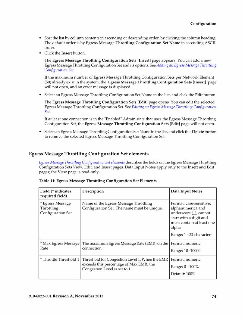
• Sort the list by column contents in ascending or descending order, by clicking the column heading.The default order is by Egress Message Throttling Configuration Set Name in ascending ASCIIorder.
• Click the Insert button.
The Egress Message Throttling Configuration Sets [Insert] page appears. You can add a newEgress Message Throttling Configuration Set and its options. See Adding an Egress Message ThrottlingConfiguration Set.
If the maximum number of Egress Message Throttling Configuration Sets per Network Element(50) already exist in the system, the Egress Message Throttling Configuration Sets [Insert] pagewill not open, and an error message is displayed.
• Select an Egress Message Throttling Configuration Set Name in the list, and click the Edit button.
The Egress Message Throttling Configuration Sets [Edit] page opens. You can edit the selectedEgress Message Throttling Configuration Set. See Editing an Egress Message Throttling ConfigurationSet.
If at least one connection is in the "Enabled" Admin state that uses the Egress Message ThrottlingConfiguration Set, the Egress Message Throttling Configuration Sets [Edit] page will not open.
• Select an Egress Message Throttling Configuration Set Name in the list, and click the Delete buttonto remove the selected Egress Message Throttling Configuration Set.
Egress Message Throttling Configuration Set elements
Egress Message Throttling Configuration Set elements describes the fields on the Egress Message ThrottlingConfiguration Sets View, Edit, and Insert pages. Data Input Notes apply only to the Insert and Editpages; the View page is read-only.
Table 11: Egress Message Throttling Configuration Set Elements
Data Input NotesDescriptionField (* indicatesrequired field)
Format: case-sensitive;alphanumerica and
Name of the Egress Message ThrottlingConfiguration Set. The name must be unique.
* Egress MessageThrottlingConfiguration Set underscore (_); cannot
start with a digit andmust contain at least onealpha
Range: 1 - 32 characters
Format: numeric
Range: 10 -10000
The maximum Egress Message Rate (EMR) on theconnection
* Max Egress MessageRate
Format: numeric
Range: 0 - 100%
Threshold for Congestion Level 1. When the EMRexceeds this percentage of Max EMR, theCongestion Level is set to 1
* Throttle Threshold 1
Default: 100%
74910-6822-001 Revision A, November 2013
Configuration

Data Input NotesDescriptionField (* indicatesrequired field)
Format: numeric
Range: 0 - 100%
Abatement Threshold for Congestion Level 1.When the EMR falls below this percentage of MaxEMR, the Congestion Level returns to 0.
* AbatementThreshold 1
Default: 80%
Format: numeric
Range: 0 - 100%
Threshold for Congestion Level 2. When the EMRexceeds this percentage of Max EMR, theCongestion Level is set to 2
Throttle Threshold 2
Default: none
Format: numeric
Range: 0 - 100%
Abatement Threshold for Congestion Level 2.When the EMR falls below this percentage of MaxEMR, the Congestion Level returns to 1.
Abatement Threshold2
Default: none
Format: numeric
Range: 0 - 100%
Threshold for Congestion Level 3. When the EMRexceeds this percentage of Max EMR, theCongestion Level is set to 3
Throttle Threshold 3
Default: none
Format: numeric
Range: 0 - 100%
Abatement Threshold for Congestion Level 3.When the EMR falls below this percentage of MaxEMR, the Congestion Level returns to 2.
Abatement Threshold3
Default: none
Format: numeric
Range: 20 - 90%
Percentage contribution of the current EMRsample to the Smoothed EMR
* Smoothing Factor
Default: 80%
Format: numeric
Range: 200 - 10000milliseconds
The amount of time a throttled connection'sSmoothed EMR must remain below an abatementthreshold before the Congestion Level is lowered.
* Abatement Time
Default: 500 milliseconds
Viewing Egress Message Throttling Configuration Sets
Use this task to view currently configured Egress Message Throttling Configuration Sets.
Select Diameter > Configuration > Configuration Sets > Egress Message Throttling ConfigurationSets.The Egress Message Throttling Configuration Sets page appears.
Adding an Egress Message Throttling Configuration Set
Use this task to create a new Egress Message Throttling Configuration Set. For more information aboutthe fields, see Egress Message Throttling Configuration Set elements.
75910-6822-001 Revision A, November 2013
Configuration

1. Select Diameter > Configuration > Configuration Sets > Egress Message Throttling ConfigurationSets.The Egress Message Throttling Configuration Sets page appears.
2. Click Insert.The Egress Message Throttling Configuration Sets [Insert] page appears.
3. Enter a unique name for the Configuration Set in the Egress Message Throttling ConfigurationSet Name field.
4. Enter the maximum Egress Message Rate in the Maximum Allowed EMR field.5. Enter one to three Throttle Thresholds and Abatement Thresholds as a percentage of the maximum
Egress Message Rate.6. Optionally, enter a Smoothing Factor and an Abatement Time.7. Click:
• OK to save the data and return to the Egress Message Throttling Configuration Sets page.• Apply to save the data and remain on this page.• Cancel to return to the Egress Message Throttling Configuration Sets page without saving
any changes.
If OK or Apply is clicked and any of the following conditions exist, an error message appears:
• Any required field is empty (no value was entered)• The value in any field is not valid or is out of range• The Egress Message Throttling Configuration Set Name is not unique; it already exists in the
system• Throttle thresholds and abatement thresholds do not follow the rule: TT3 > AT3 > TT2 > AT2
> TT1 > AT1• The maximum number of Egress Message Throttling Configuration Sets per Network Element
(50) is already configured
Editing an Egress Message Throttling Configuration Set
Use this task to edit an existing Egress Message Throttling Configuration Set.
When the Egress Message Throttling Configuration Sets page opens, the fields are populated withthe currently configured values.
The Egress Message Throttling Configuration Set Name cannot be edited.
1. Select Diameter > Configuration > Configuration Sets > Egress Message Throttling ConfigurationSets.The Egress Message Throttling Configuration Sets page appears.
2. Select the Egress Message Throttling Configuration Set you want to edit.3. Click Edit.
The Egress Message Throttling Configuration Sets [Edit] page appears.4. Update the relevant fields.
For information about each field, see Egress Message Throttling Configuration Set elements.
5. Click:
• OK to save the data and return to the Egress Message Throttling Configuration Sets page.
76910-6822-001 Revision A, November 2013
Configuration

• Apply to save the data and remain on this page.• Cancel to return to the Egress Message Throttling Configuration Sets page without saving
any changes.
If OK or Apply is clicked and any of the following conditions exist, an error message appears:
• The selected Egress Message Throttling Configuration Set no longer exists; it has been deletedby another user
• Any field is empty (no value was entered)• The value in any field is not valid or is out of range• Throttle thresholds and abatement thresholds do not follow the rule: TT3 > AT3 > TT2 > AT2
> TT1 > AT1
Deleting an Egress Message Throttling Configuration Set
Use this task to delete an Egress Message Throttling Configuration Set.
Note: An Egress Message Throttling Configuration Set cannot be deleted if it is being used by anyconnections. Before you perform this task, you must disable and edit any connections that use theEgress Message Throttling Configuration Set. (See Disabling Connections and Editing a Connection.)
1. Select Diameter > Configuration > Configuration Sets > Egress Message Throttling ConfigurationSets.The Egress Message Throttling Configuration Sets page appears.
2. Select the Egress Message Throttling Configuration Set you want to delete.3. Click Delete.
A popup window appears to confirm the delete.4. Click:
• OK to delete the Egress Message Throttling Configuration Set.• Cancel to cancel the delete function and return to the Egress Message Throttling Configuration
Sets page.
If OK is clicked and the selected Egress Message Throttling Configuration Set is referenced by atleast one connection, an error message appears and the Egress Message Throttling ConfigurationSet is not deleted.
If OK is clicked and the selected Egress Message Throttling Configuration Set no longer exists (itwas deleted by another user), an error message is displayed and the Egress Message ThrottlingConfiguration Sets view is refreshed.
Message Priority Configuration Set configuration
A Message Priority Configuration Set provides a mechanism for controlling how message priority isset for a request message arriving on a connection. A Message Priority Configuration Set contains oneor more Message Priority Rules.
77910-6822-001 Revision A, November 2013
Configuration

A Message Priority Rule consists of combination of an Application ID and a Command Code, and apriority. Incoming messages that match the Application ID and Command Code are assigned theassociated priority.
Message Priority Configuration Sets can be assigned to Connections or Peer Nodes.
The Message Priority Configuration Set fields are described in Message Priority Configuration Set elements.
On the Message Priority Configuration Sets page, you can perform the following actions:
• Filter the list of Message Priority Configuration Sets to display only the desired Message PriorityConfiguration Sets.
• Sort the list by column contents in ascending or descending order, by clicking the column heading.The default order is by Message Priority Configuration Set Name in ascending ASCII order.
• Click the + in the Message Priority Rules field to display the Message Priority Rules associatedwith a Message Priority Configuration Set.
• Click the Insert button.
The Message Priority Configuration Sets [Insert] page appears. You can add a new MessagePriority Configuration Set and its Message Priority Rules. See Adding a Message Priority ConfigurationSet.
If the maximum number of Message Priority Configuration Sets per Network Element (20) alreadyexist in the system, the Message Priority Configuration Sets [Insert] page will not open, and anerror message is displayed.
• Select an Message Priority Configuration Set Name in the list, and click the Edit button.
The Message Priority Configuration Sets [Edit] page opens. You can edit the selected MessagePriority Configuration Set. See Editing a Message Priority Configuration Set.
If at least one connection that uses the Message Priority Configuration Set is in the "Enabled" Adminstate, the Message Priority Configuration Sets [Edit] page will not open.
• Select an Message Priority Configuration Set Name in the list, and click the Delete button to removethe selected Message Priority Configuration Set. You cannot delete the Default Message PriorityConfiguration Set.
Message Priority Configuration Set elements
Table 12: Message Priority Configuration Set Elements describes the fields on the Message PriorityConfiguration Sets View, Edit, and Insert pages. Data Input Notes apply only to the Insert and Editpages; the View page is read-only.
Table 12: Message Priority Configuration Set Elements
Data Input NotesDescriptionField (* indicates arequired field)
Format: Case-sensitivestring: alphanumeric and
Unique name of the Message PriorityConfiguration Set.
* Message PriorityConfiguration Set Name
underscore (_); mustcontain at least one alpha
78910-6822-001 Revision A, November 2013
Configuration

Data Input NotesDescriptionField (* indicates arequired field)
and cannot begin with adigit.
Range: 1 - 32 characters
The number of Message Priority Rules definedin the Message Priority Configuration Set
* Message Priority Rules
Format: scrollable list
Range: configuredApplication Ids. An
The Application Id used to filter incomingDiameter messages
Application Id
asterisk (*) matches anyApplication Id.
The name of the application associated withthe Application Id
Application Name
Format: scrollable list
Range: configuredCommand Codes. An
The Command Code used to filter incomingDiameter messages.
Command Code
asterisk (*) matches anyCommand Code.
The name of the command associated withthe Command Code
Command Code Name
Format: pull down listThe message priority assigned to incomingmessages that match the combination ofApplication Id and Command Code.
Priority
Range: 0-2
Viewing Message Priority Configuration Sets
Use this task to view currently configured Message Priority Configuration Sets and their associatedMessage Priority Rules.
1. Select Diameter > Configuration > Configuration Sets > Message Priority Configuration Sets.The Message Priority Configuration Sets page appears.
2. Click the + in any Message Priority Rules field.The Message Priority Rules associated with the Message Priority Configuration Set are displayed.
Adding a Message Priority Configuration Set
Use this task to create a new Message Priority Configuration Set. For more information about thefields, see Message Priority Configuration Set elements.
1. Select Diameter > Configuration > Configuration Sets > Message Priority Configuration Sets.The Message Priority Configuration Sets page appears.
2. Click Insert.
79910-6822-001 Revision A, November 2013
Configuration

The Message Priority Configuration Sets [Insert] page appears.3. Enter a unique name for the Configuration Set in the Message Priority Configuration Set Name
field.4. Select an Application Id, Command Code, and Message Priority for the Message Priority Rule.5. Click Add to add more Message Priority Rules to the Message Priority Configuration Set.
You can add up to 50 rules per configuration set. Click the X beside the Message Priority field toclear the values for a Message Priority Rule.
6. Click:
• OK to save the data and return to the Message Priority Configuration Sets page.• Apply to save the data and remain on this page.• Cancel to return to the Message Priority Configuration Sets page without saving any changes.
If OK or Apply is clicked and any of the following conditions exist, an error message appears:
• Any required field is empty (no value was entered)• The value in any field is not valid or is out of range• The Message Priority Configuration Set Name is not unique; it already exists in the system• A wildcard is used for Application Id, but a specific Command Code is specified.• The maximum number of Message Priority Configuration Sets per Network Element (20) is
already configured
Editing a Message Priority Configuration Set
Use this task to edit an existing Message Priority Configuration Set.
When the Message Priority Configuration Sets page opens, the fields are populated with the currentlyconfigured values.
The Message Priority Configuration Set Name cannot be edited.
1. Select Diameter > Configuration > Configuration Sets > Message Priority Configuration Sets.The Message Priority Configuration Sets page appears.
2. Select the Message Priority Configuration Set you want to edit.3. Click Edit.
The Message Priority Configuration Sets [Edit] page appears.4. Update the relevant fields.
For information about each field, see Message Priority Configuration Set elements.
5. Click:
• OK to save the data and return to the Message Priority Configuration Sets page.• Apply to save the data and remain on this page.• Cancel to return to the Message Priority Configuration Sets page without saving any changes.
If OK or Apply is clicked and any of the following conditions exist, an error message appears:
• The selected Message Priority Configuration Set no longer exists; it has been deleted by anotheruser
• Any field is empty (no value was entered)• The value in any field is not valid or is out of range
80910-6822-001 Revision A, November 2013
Configuration

• A wildcard (*) is used for Application Id, but a specific Command Code is specified.
Deleting a Message Priority Configuration Set
Use this task to delete a Message Priority Configuration Set.
Note: The default Message Copy Configuration Set cannot be deleted.
1. Select Diameter > Configuration > Configuration Sets > Message Priority Configuration Sets.The Message Priority Configuration Sets page appears.
2. Select the Message Priority Configuration Set you want to delete.3. Click Delete.
A popup window appears to confirm the delete.4. Click:
• OK to delete the Message Priority Configuration Set.• Cancel to cancel the delete function and return to the Message Priority Configuration Sets
page.
If OK is clicked and the selected Message Priority Configuration Set is referenced by at least oneconnection, an error message appears and the Message Priority Configuration Set is not deleted.
If OK is clicked and the selected Message Priority Configuration Set no longer exists (it was deletedby another user), an error message is displayed and the Message Priority Configuration Sets viewis refreshed.
Message Copy Configuration Set configuration
A Message Copy Configuration Set provides a mechanism for determining the messages to be copied(Request or Answer), the Result-Code/Experimental Result-Code on which the Message Copy isinitiated, and number of retries to be made if the Message Copy attempt to DAS fails. The MessageCopy trigger point must specify a Message Copy Configuration Set when the message is marked forcopying.
The Message Copy Configuration Set fields are described in Message Copy Configuration Set elements.
On the Message Copy Configuration Sets page, you can perform the following actions:
• Filter the list of Message Copy Configuration Sets to display only the desired Message CopyConfiguration Sets.
• Sort the list by column contents in ascending or descending order, by clicking the column heading.The default order is by Message Copy Configuration Set Name in ascending ASCII order.
• Click the Insert button.
The Message Copy Configuration Sets [Insert] page appears. You can add a new Message CopyConfiguration Set. See Adding a Message Copy Configuration Set.
If the maximum number of Message Copy Configuration Sets (100) already exists in the system,an error message is displayed.
• Select a Message Copy Configuration Set Name in the list, and click the Edit button.
81910-6822-001 Revision A, November 2013
Configuration

The Message Copy Configuration Sets [Edit] page opens. You can edit the selected Message CopyConfiguration Set. See Editing a Message Copy Configuration Set.
If no row is selected, or if more than one row is selected, the Edit button is disabled.
• Select a Message Copy Configuration Set Name in the list, and click the Delete button to removethe selected Message Copy Configuration Set.
The Default Message Copy Configuration Set can be edited, but cannot be deleted. See Deleting aMessage Copy Configuration Set.
Message Copy Configuration Set elements
Table 12: Message Priority Configuration Set Elements describes the fields on the Message CopyConfiguration Sets View, Edit, and Insert pages. Data Input Notes apply only to the Insert and Editpages; the View page is read-only.
Table 13: Message Copy Configuration Set Elements
Data Input NotesDescriptionField (* indicates arequired field)
Format: text boxUnique name of the Message CopyConfiguration Set.
* Message CopyConfiguration Set Name Case-sensitive string:
alphanumeric andunderscore (_); must containat least one alpha andcannot begin with a digit.
Range: 1 - 32 characters
Format: pulldown listRoute List to be used for copying a messageto a DAS node.
* Route List for DAS Node
Range: configured RouteLists.
Default: "-Select-".
Format: radio buttonsType of Request to be copied to the DAS.Message Copy RequestType Range: Original Ingress
Request, Original EgressRequest
Default: Original IngressRequest
Format: radio buttonsIndicates whether the Ingress Answerreceived for the Diameter Message needsto be included in the copied message.
Ingress Answer Included
Range: Yes, No
Default: No
Format: radio buttonsResult Code/Experimental Result code thatshould match with incoming Answer Result
Original Answer ResultCode For Message Copy Range:
82910-6822-001 Revision A, November 2013
Configuration

Data Input NotesDescriptionField (* indicates arequired field)
Code (whose Request has been marked forMessage Copy), to allow copying a Requestto DAS.
• 2xxx result-code/experimental-result-code
• Any result/experimental-result-code
Default: 2xxx result-code/experimental-result-code
Format: radio buttonsResult Code/Experimental Result Code thatshould match with DAS Message Copy
DAS Answer Result Code
Range:Answer Result Code, to terminate theMessage Copy to DAS. • 2xxx result-code/
experimental-result-code• Any result/
experimental-result-code
Default: 2xxx result-code/experimental-result-code
Format: text box; numericMax Retransmission Attempts forDAS-Request
* Max DAS RetransmissionAttempts Range: 0-4
A value of 0 indicates that there will not beany re-transmissions after the first copyattempt.
Default: 0
Viewing Message Copy Configuration Sets
Use this task to view currently configured Message Copy Configuration Sets.
Select Diameter > Configuration > Configuration Sets > Message Copy Configuration Sets.The Message Copy Configuration Sets page appears.
Adding a Message Copy Configuration Set
Use this task to create a new Message Copy Configuration Set.
The fields are described in Message Priority Configuration Set elements.
1. Select Diameter > Configuration > Configuration Sets > Message Copy Configuration Sets.The Message Copy Configuration Sets page appears.
2. Click Insert.The Message Copy Configuration Sets [Insert] page appears.
If the maximum numbers of Message Copy Configuration Sets (100) allowed in the system arealready configured, the Message Copy Configuration Sets [Insert] page will not open.
3. Enter a unique name for the Configuration Set in the Message Copy Configuration Set Namefield.
83910-6822-001 Revision A, November 2013
Configuration

4. Select or enter the element values.5. Click:
• OK to save the new Configuration Set and return to the Message Copy Configuration Setspage.
• Apply to save the new Configuration Set and remain on this page.• Cancel to return to the Message Copy Configuration Sets page without saving any changes.
If OK or Apply is clicked and any of the following conditions exist, an error message appears:
• Any required field is empty (no value was entered).• The value in any field is not valid or is out of range.• The Message Copy Configuration Set Name is not unique; it already exists in the system.
Editing a Message Copy Configuration Set
Use this task to edit an existing Message Copy Configuration Set.
When the Message Copy Configuration Sets page opens, the fields are populated with the currentlyconfigured values.
The Message Copy Configuration Set Name cannot be edited.
The fields are described in Message Copy Configuration Set elements.
1. Select Diameter > Configuration > Configuration Sets > Message Copy Configuration Sets.The Message Copy Configuration Sets page appears.
2. Select the Message Copy Configuration Set you want to edit.3. Click Edit.
The Message Copy Configuration Sets [Edit] page appears.4. Update the relevant fields.5. Click:
• OK to save the changes and return to the Message Copy Configuration Sets page.• Apply to save the changes and remain on this page.• Cancel to return to the Message Copy Configuration Sets page without saving any changes.
If OK or Apply is clicked and any of the following conditions exist, an error message appears:
• The selected Message Copy Configuration Set no longer exists; it has been deleted by anotheruser.
• Any field is empty (no value was entered) .• The value in any field is not valid or is out of range.
Deleting a Message Copy Configuration Set
Use this task to delete a Message Copy Configuration Set.
The Default Message Copy Configuration Set can be edited, but cannot be deleted.
1. Select Diameter > Configuration > Configuration Sets > Message Copy Configuration Sets.The Message Copy Configuration Sets page appears.
84910-6822-001 Revision A, November 2013
Configuration
2. Select the Message Copy Configuration Set you want to delete.3. Click Delete.
A popup window appears to confirm the delete.4. Click:
• OK to delete the Message Copy Configuration Set.• Cancel to cancel the delete function and return to the Message Copy Configuration Sets page.
If OK is clicked and the selected Message Copy Configuration Set is referenced by any otherDiameter component or any DSR Application, an error message appears and the Message CopyConfiguration Set is not deleted.
Local Node configuration
A Local Node is a local Diameter node that is specified with a realm and an FQDN. The DSR supportsup to 32 Local Nodes.
The Local Node identifies:
• Domain information• SCTP Listen Port Number• TCP Listen Port Number• The supported transport type(s)• A list of IP addresses available for establishing Diameter transport connections
After it is configured, a Local Node can be assigned to connections for use in Diameter routing.
On the Diameter > Configuration > Local Nodes page, you can perform the following actions:
• Filter the list of Local Nodes to display only the desired Local Nodes.• Sort the list by a column in ascending or descending order, by clicking the column heading (except
IP Addresses). The default order is by Local Node Name in ascending ASCII order.• Click a field entry that is shown in blue for a Local Node. The blue entries are links to the
configuration pages for those types of items.
The Diameter > Configuration > {Item Type} (Filtered) page appears for the selected item.
• Click Insert.
The Diameter > Configuration > Local Nodes [Insert] page appears. You can add a new LocalNode.
The Diameter > Configuration > Local Nodes [Insert] page will not open if any of the followingconditions exist:
• The maximum number of Local Nodes (32) has already been configured.• There is no Signaling VIP Address available in the signaling Network Element (NE) that can
be added to the Local Node.
• Select a Local Node in the list, and click Edit.
The Diameter > Configuration > Local Nodes [Edit] page appears. You can edit the selected LocalNode.
85910-6822-001 Revision A, November 2013
Configuration

• Select a Local Node in the list, and click Delete. You can delete the selected Local Node.
Local Node configuration elements
Table 14: Local Node Configuration Elements describes the fields on the Local Nodes View, Insert, andEdit pages. Data Input Notes only apply to the Insert and Edit pages; the View page is read-only.
Table 14: Local Node Configuration Elements
Data Input NotesDescriptionField (* indicatesrequired field)
Format: string,case-sensitive;
Unique name of the Local Node.* Local Node Name
alphanumeric andunderscore (_); cannotstart with a digit andmust contain at leastone alpha
Range: 1 - 32 characters
Format: stringconsisting of a list of
Realm of the Local Node; defines theadministrative domain with which the usermaintains an account relationship.
* Realm
labels separated by dots.A label can containletters, digits, dash (-),and underscore (_). Alabel must begin with aletter, digit, orunderscore, and mustend with a letter ordigit. Underscore can beused only as the firstcharacter.
Range: Realm - up to255 characters; label - upto 63 characters
Format: stringconsisting of a list of
Unique Fully Qualified Domain Name; specifiesexact location in the tree hierarchy of the DNS.
* FQDN
labels separated by dots.A label must containletters, digits, dash (-),and underscore (_). Alabel must begin with aletter or underscore, andmust end with a letteror digit. Underscore canbe used only as the firstcharacter.
86910-6822-001 Revision A, November 2013
Configuration

Data Input NotesDescriptionField (* indicatesrequired field)
Range: FQDN - up to255 characters; label - upto 63 characters
Format: numericSCTP listen port number for the Local Node. TheSCTP Enabled box must be checked before a valuecan be entered in this field.
SCTP Listen Port
Range: 1024 - 65535
Default: 3868This SCTP Listen Port cannot be the same as aLocal Initiate Port of a Connection.
Format: numericTCP listen port number for the Local Node. TheTCP Enabled box must be checked before a valuecan be entered in this field.
TCP Listen Port
Range: 1024 - 65535
Default: 3868This TCP Listen Port cannot be the same as a LocalInitiate Port of a Connection.
Format: pulldown listConnection Configuration Set for the Local Node.* ConnectionConfiguration Set Range: configured
ConnectionConfiguration Sets,"Default" ConnectionConfiguration Set
Format: pulldown listCEX Configuration Set associated with the LocalNode.
* CEX Configuration Set
Range: configured CEXConfiguration Sets,The entries in the CEX Configuration Set field
create links to the Diameter > Configuration > "Default" CEXConfiguration Set.CEX Configuration Sets (Filtered) page, which
shows only the selected entry.
The CEX Configuration Set field for the LocalNode is used if the CEX Configuration Set is notassociated with the Connection.
Format: 128 pulldownlists
IP address, or addresses, available for establishingDiameter transport Connections to the Local
* IP Addresses
Node. You must assign at least one IP Address, Range:and can assign up to 128 IP addresses, to a Local• For a DSR that has
Active/StandbyNode. Up to 32 IP addresses can be IPFE TargetSet Addresses.
DA-MPs: availableIf fewer than four XSI interfaces are configuredand SCTP transport is selected, then the number Virtual Signaling IP
Addresses ,of IP Addresses selected must be the same as thenumber of XSI interfaces. including any
configured IPFEprimary andsecondary TSAs VIP
On the Local Nodes GUI pages, each IP addresshas appended to it:
87910-6822-001 Revision A, November 2013
Configuration

Data Input NotesDescriptionField (* indicatesrequired field)
• For VIP addresses, the string "VIP"
VIPs are present only in 1+1 Active/Standbyconfigurations
• For a DSR that hasMultiple-ActiveDA-MPs: static IPaddressesconfigured for each• For static IP addresses, the MP Server
Hostname of the DA-MP that owns the IPaddress
Static IP addresses are present only inMulti-Active N+0 configurations
DA-MP, includingany configured IPFEprimary andsecondary TSAs
• configured IPFEprimary andsecondary TSAs
• For TSAs, the name of the Target Set to whichthe IP address corresponds, followed by -p or-s (for example, TSA#-p for primary andTSA#-s for secondary IP Addresses where "#"is the Target Set number
TSAs can be present in either, but do not haveto be present at all.
Viewing Local Nodes
Use this task to view currently configured Local Nodes.
Select Diameter > Configuration > Local Nodes.The Diameter > Configuration > Local Nodes page appears.
Adding a Local Node
Use this task to create a new Local Node.
1. Select Diameter > Configuration > Local Nodes.The Diameter > Configuration > Local Nodes page appears.
2. Click Insert.The Diameter > Configuration > Local Nodes [Insert] page appears.
3. Enter a unique name for the Local Node in the Local Node Name field.4. Enter the Realm for the Local Node in the field.5. Enter an FQDN in the field.6. If you want the Local Node to listen for SCTP connections, check the SCTP Enabled check box.7. If SCTP Enabled is checked, enter an SCTP Listen Port number in the field.
This is the port that will be used by connections that use this Local Node to listen for SCTP requestmessages. The default 3868 is the well-known IANA port for Diameter traffic.
8. If you want the Local Node to listen for TCP connections, check the TCP Enabled check box.9. If TCP Enabled is checked, enter a TCP Listen Port number in the field.
88910-6822-001 Revision A, November 2013
Configuration
This is the port that will be used by connections that use this Local Node to listen for TCP requestmessages. The default 3868 is the well-known IANA port for Diameter traffic.
10. Select a Connection Configuration Set from the pulldown list. If you have not added additionalConnection Configuration Sets, only the Default Connection Configuration Set will be available.
11. Select a CEX Configuration Set for the Local Node from the pulldown list.If you have not added additional CEX Configuration Sets, only the Default CEX Configuration Setwill be available.
12. Select from 1 to 128 IP addresses from the IP Addresses pulldown lists.13. Click:
• OK to save the new Local Node and return to the Diameter > Configuration > Local Nodespage.
• Apply to save the new Local Node and remain on this page.• Cancel to return to the Diameter > Configuration > Local Nodes page without saving any
changes.
If OK or Apply is clicked and any of the following conditions exist, an error message appears:
• The maximum number of Local Nodes (32) per Network Element is already defined in thesystem
• Any required field is empty; no value was entered or selected• The entry in any field is not valid (wrong data type or out of the valid range)• The selected pulldown list entry no longer exists (has been deleted by another user)• The Local Node Name is not unique; it already exists in the system• The FQDN is already assigned to a different Local or Peer Node• Neither the SCTP Enabled check box nor the TCP Enabled check box is checked; one must be
checked• The SCTP Listen Port and IP Address combination is already assigned to a different Local or
Peer Node• The TCP Listen Port and IP Address combination is already assigned to a different Local or
Peer Node• The SCTP Listen Port or the TCP Listen Port is already used as a Local Initiate Port of a
Connection• Any of the selected IP Addresses is duplicated
Editing a Local Node
Use this task to edit a Local Node.
When the Diameter > Configuration > Local Nodes [Edit] page opens, the fields are initially populatedwith the current values for the selected Local Node.
Configuration considerations:
• The Local Node Name cannot be changed.• The following fields cannot be edited if there is at least one associated Enabled connection:
• Realm• FQDN• SCTP Listen Port (and the Transport Protocol is SCTP)
89910-6822-001 Revision A, November 2013
Configuration
• TCP Listen Port (and the Transport Protocol is TCP)• IP Address (cannot be removed if there is an Enabled connection, but a new IP Address can be
added)• Connection Configuration Set• CEX Configuration Set
1. Select Diameter > Configuration > Local Nodes.The Diameter > Configuration > Local Nodes page appears.
2. Select the Local Node you want to edit, then click Edit.The Diameter > Configuration > Local Nodes [Edit] page appears.
3. Update the relevant fields.
For more information about each field, see Local Node configuration elements.
The value for an entry in a pulldown list can be removed by selecting "--Select—" in the list, orselecting the X at the end of the list box (if an X is available).
4. Click:
• OK to save the data and return to the Diameter > Configuration > Local Nodes page.• Apply to save the data and remain on this page.• Cancel to return to the Diameter > Configuration > Local Nodes page without saving any
changes.
If OK or Apply is clicked and any of the following conditions exist, an error message appears:
• The selected Local Node no longer exists; it has been deleted by another user• The selected IP Address or Connection Configuration Set has been deleted by another user• Any required field is empty; no value was entered or selected• The entry in any field is not valid (wrong data type or out of the valid range)• The selected pulldown list entry no longer exists (has been deleted by another user)• The edited FQDN is already assigned to a different Local or Peer Node• Neither the SCTP Enabled check box nor the TCP Enable check box is checked; at least one of
them must be checked• SCTP Enabled was changed to be disabled (unchecked) and there is at least one associated
SCTP connection.• TCP Enabled was changed to be disabled (unchecked) and there is at least one associated TCP
connection.• The edited IP Address and SCTP Listen Port combination is already assigned to a different
Local Node or Peer Node• The edited IP Address and TCP Listen Port combination is already assigned to a different Local
Node or Peer Node• The selected SCTP Listen Port or TCP Listen Port is already used as a Local Initiate Port of a
connection
Deleting a Local Node
Use this task to delete a Local Node.
Note: A Local Node cannot be deleted if it is being used by any connections. Before you perform thistask, disable and delete any connections that use the Local Node.
90910-6822-001 Revision A, November 2013
Configuration

1. Select Diameter > Configuration > Local Nodes.The Diameter > Configuration > Local Nodes page appears.
2. Select the Local Node you want to delete.3. Click Delete.
A pop up window appears to confirm the delete.
4. Click:
• OK to delete the Local Node.
• Cancel to cancel the delete function and return to the Diameter > Configuration > Local Nodespage.
If OK is clicked and the selected Local Node no longer exists (it was deleted by another user), anerror message is displayed and the Local Nodes view is refreshed.
Peer Node configuration
A Peer Node is an external Diameter client, server, or agent with which the DSR establishes directtransport connections. A Peer Node may be a single computer or a cluster of computers and may haveone or more transport connections.
After it is configured, a Peer Node can be:
• Assigned to connections for use in Diameter routing• Assigned to Route Groups that manage the distribution of traffic to and among Peer Nodes
On the Diameter > Configuration > Peer Nodes page, you can perform the following actions:
• Filter the list of Peer Nodes, to display only the desired Peer Nodes.• Sort the list by a column in ascending or descending order, by clicking the column heading (except
IP Addresses). The default order is by Peer Node Name in ascending ASCII order.• Click an entry that is shown in blue in a column, to open the Diameter > Configuration >
<component> [Filtered] page and display that entry only.• Click Insert.
The Diameter > Configuration > Peer Nodes [Insert] page appears. You can add a new Peer Node.
The Diameter > Configuration > Peer Nodes [Insert] will not open if the maximum number ofPeer Nodes per Network Element (6000) already exists in the system.
• Select a Peer Node in the list, and click Edit.
The Diameter > Configuration > Peer Notes [Edit] page appears. You can edit the selected PeerNode.
• Select a Peer Node in the list, and click Delete. You can delete the selected Peer Node.
91910-6822-001 Revision A, November 2013
Configuration

Peer Node configuration elements
Table 15: Peer Node Configuration Elements describes the fields on the Peer Nodes View, Insert, and Editpages. Data Input Notes apply only to the Insert and Edit pages; the View page is read-only.
Table 15: Peer Node Configuration Elements
Data Input NotesDescriptionField (* indicatesrequired field)
Format: string,case-sensitive;
Unique name of the Peer Node.* Peer Node Name
alphanumeric andunderscore (_); cannotstart with a digit andmust contain at least onealpha
Range: 1 - 32 characters
Format: string consistingof a list of labels
Realm of the Peer Node.* Realm
separated by dots. Alabel must contain letters,digits, dash (-), andunderscore (_). A labelmust begin with a letteror underscore, and mustend with a letter or digit.Underscore can be usedonly as the firstcharacter.
Range: up to 255characters; label - up to63 characters
Format: string consistingof a list of labels
Unique Fully Qualified Domain Name; specifiesexact location in the tree hierarchy of the DNS.
* FQDN
separated by dots. Alabel must contain letters,digits, dash (-), andunderscore (_). A labelmust begin with a letteror underscore, and mustend with a letter or digit.Underscore can be usedonly as the firstcharacter.
Range: FQDN - up to 255characters; label - up to63 characters
92910-6822-001 Revision A, November 2013
Configuration

Data Input NotesDescriptionField (* indicatesrequired field)
Format: numericSCTP Listen Port Number for the Peer Node.SCTP Listen Port
Range: 1024 - 65535The SCTP Enabled box must be checked beforea value can be entered in this field. Default: 3868
Format: numericTCP Listen Port Number for the Peer Node.TCP Listen Port
Range: 1024 - 65535The TCP Enabled box must be checked before avalue can be entered in this field. Default: 3868
Format: numericIP address, or addresses, available forestablishing Diameter transport connections tothe Peer Node.
IP Addresses
Range: up to 128 valid IPAddresses
View - Each Peer Node entry displays a + signand the number of IP Addresses assigned to thatPeer Node. Click the + sign to display the IPAddresses; the + sign changes to a - sign. Clickthe - sign to display the number again.
[Insert] and [Edit] - The field contains an Addbutton that can be clicked up to 127 times tocreate 128 text boxes for IP Addresses. Each entryis numbered, to indicate the number of IPAddresses that have been added.
Format: pulldown listRoute List to use for routing messages to thisPeer Node if all Peer Routing Rules and implicitPeer Routes are unavailable.
Alternate Implicit Route
Range: configured RouteLists
Each entry in the Alternate Implicit Routecolumn on the View page is a link to the Default: "-Select-"
Diameter > Configuration > Route List[Filtered] page for the selected entry only.
Format: check boxIf checked, the Destination Realm AVP ofoutgoing messages will be overwritten with thisPeer Node Realm.
Replace Dest Realm
Range: checked,unchecked
Default: unchecked
Format: check boxIf checked, the Destination Host AVP of outgoingmessages will be overwritten with this Peer NodeFQDN.
Replace Dest Host
Range: checked,unchecked
Default: unchecked
Format: pulldown listIf Enabled, Diameter Topology Hiding will beapplicable to this Peer Node.
Topology Hiding Status
Range = Disabled,Enabled
93910-6822-001 Revision A, November 2013
Configuration

Data Input NotesDescriptionField (* indicatesrequired field)
Default = Disabled
Format: numericThe minimum number of connections that mustbe available to this Peer in order for it to be
* Minimum ConnectionCapacity Range: 1-64"Available". Otherwise, the Peer is "Degraded"
if fewer than the minimum number of Default: 1connections are "Available", or "Unavailable" ifno connections are "Available".
Format: numericThe maximum number of times that a Requestcan be rerouted to this Peer before the nexteligible Peer is selected.
* Maximum AlternateRouting Attempts Range: 1-4
Default: 4
Format: radio buttonsIndicates whether to perform alternate routingon alternate connections to the same Peer before
Alternate Routing OnConnection Failure Range: Same Peer,
Different Peerselecting the next eligible Peer of a Peer RouteGroup, when a connection failure occurs.
Default: Different Peer
Format: radio buttonsIndicates whether to perform alternate routingon the same connection or on alternate
Alternate Routing OnAnswer Timeout Range: Same Peer,
Different Peer, SameConnection
connections to the same Peer before selecting thenext eligible Peer of a Peer Route Group, whenan Answer Timeout occurs.
Default: Different Peer
Format: radio buttonsIndicates whether to perform alternate routingon alternate connections to the same Peer before
Alternate Routing OnAnswer Result Code Range: Same Peer,
Different Peerselecting the next eligible Peer of a Peer RouteGroup, when a reroute on Answer Result Codeoccurs. Default: Different Peer
For an Answer response received from a DASPeer, alternate routing on Answer Result Codeis determined by the Diameter > Configuration> Message Copy Configuration Set > OriginalAnswer Result Code for Message Copyparameter.
Format: pulldown listThe Application Route Table associated with thisPeer Node.
If Application Route Table is set to is NotSelected, the downstream Application Ids
Application Route Table
Range: Default,configured ApplicationRoute Tables
associated Application Route Table will be usedwhen processing transactions if it is defined. Default: Not Selected
Format: pulldown listThe Peer Route Table associated with the PeerNode. The Peer Route Table contains Peer
Peer Route Table
94910-6822-001 Revision A, November 2013
Configuration

Data Input NotesDescriptionField (* indicatesrequired field)
Range: Default,configured Peer RouteTables
Routing Rules used to route messages from thePeer Node.
If Peer Route Table is set to Not Selected, thePeer Route Table configured for the ApplicationId contained in the message is used.
Default: Not Selected
Format: pulldown listThe Routing Option Set associated with the PeerNode. Routing Option Sets contain informationused to handle delivery error conditions.
If Ingress Routing Option Set is set to NotSelected, the downstream Application Id's
Ingress Routing OptionSet Range: Default,
configured RoutingOption Sets
Default: Not Selectedassociated Routing Option Set will be used whenprocessing transactions if it is defined.
Format: pulldown listThe Pending Answer Timer associated with theegress Peer Node.
If Egress Pending Answer Timer is set to NotSelected, the downstream Application Id's
Egress Pending AnswerTimer Range: Default,
configured PendingAnswer Timers
associated Pending Answer Timer will be usedwhen processing transactions if it is defined. Default: Not Selected
Format: radio buttonsDefines the source of Message Priority for arequest message arriving on a Connectionassociated with the Peer Node.
The Message Priority setting for the Connectiontakes precedence over the Message Prioritysetting for the Peer Node.
Message Priority Setting
Range: None, Read fromRequest Message, UserConfigured
Default: None
Possible settings are:
• None - use the Default Message PriorityConfiguration Set
• Read from Request Message - read theMessage Priority from the ingress Request
• User Configured - Apply the user-configuredMessage Priority Configuration Set
Format: pulldown list
Range: Default,configured Message
The Message Priority Configuration set used ifUser Configured is selected for the MessagePriority Setting
Message PriorityConfiguration Set
Priority ConfigurationSets
Default: "-Select-"
95910-6822-001 Revision A, November 2013
Configuration

Viewing Peer Nodes
Use this task to view currently configured Peer Nodes.
Select Diameter > Configuration > Peer Nodes.The Diameter > Configuration > Peer Nodes page appears.
Adding a Peer Node
Use this task to create a new Peer Node.
1. Select Diameter > Configuration > Peer Nodes.The Diameter > Configuration > Peer Nodes page appears.
2. Click Insert.The Diameter > Configuration > Peer Nodes [Insert] page appears.
3. Enter a unique name for the Peer Node in the Peer Node Name field.4. Enter the Realm in the Realm field.5. Enter a Fully Qualified Domain Name in the FQDN field.6. If you want the Peer Node to support SCTP, click the SCTP Enabled check box (a check mark
appears in the box).7. If SCTP Enabled is checked, enter a port number in the SCTP Listen Port field.8. If you want the Peer Node to support TCP, check the TCP Enabled box.9. If TCP Enabled is checked, enter a port number in the TCP Listen Port field.10. Enter IP addresses in the IP Addresses fields.
An IP address is optional if a Primary DNS Server IP Address is configured. See DNS Optionsconfiguration.
To add the first IP Address, enter the IP address in the text box.
To add another IP Address, click the Add button and enter the IP Address in the new text box. SeeTable 15: Peer Node Configuration Elements for limitations on the number of IP addresses you canadd.
11. Select a Route List from the Alternate Implicit Route pulldown listThis field is optional. This Route List will be used for routing if the Connection to the Peer is downand a message does not match any of the configured Peer Routing Rules.
12. To overwrite the Destination Realm of outgoing messages to the peer with the Peer Realm, clickthe Replace Dest Realm check box (a check mark appears in the box).
13. To overwrite the Destination Host of outgoing messages to the peer with the Peer Node's FQDN,click the Replace Dest Host check box (a check mark appears in the box).
14. In the Minimum Connection Capacity text box, enter the minimum number of Connections thatmust be "Available" for the Peer to be "Available".
15. In the Maximum Alternate Routing Attempts text box, enter the maximum number of times thata Request can be rerouted to this Peer.
16. Select the Alternate Routing on Connection Failure radio button to indicate whether or not toperform alternate routing to the same or a different Peer when a Connection failure occurs.
96910-6822-001 Revision A, November 2013
Configuration

17. Select the Alternate Routing on Answer Timeout radio button to indicate whether or not to performalternate routing to the same or a different Peer, or the same Connection, when an Answer Timeoutoccurs.
18. Select the Alternate Routing on Answer Result Code radio button to indicate whether or not toperform alternate routing to the same or a different Peer when a Reroute on Answer Result Codeoccurs.
19. Select a Message Priority Setting to indicate the source of message priority for request messagesarriving on Connections associated with the Peer Node.
20. If Message Priority Setting is set to User Configured, specify the Message Priority ConfigurationSet that is used to determine message priority.
21. Select the Application Route Table to specify which Application Routing Rules are used whenrouting messages from the Peer Node.If Application Route Table is set to Not Selected, the Application Route Table configured for theApplication Id contained in the message is used.
22. Select the Peer Route Table to specify which Peer Routing Rules are used when routing messagesfrom the Peer Node.If Peer Route Table is set to Not Selected, the Peer Route Table configured for the Application Idcontained in the message is used.
23. Select the Routing Option Set to specify which options are used when certain routing failuresoccur.If Routing Option Set is set to Not Selected, the Routing Option Set configured for the ApplicationId contained in the message is used.
24. Select the Pending Answer Timer to specify how long DSR waits for a response from the PeerNode.If Pending Answer Timer is set to Not Selected, the Pending Answer Timer configured for theApplication Id contained in the message is used.
• OK to save the changes and return to the Diameter > Configuration > Peer Nodes page.• Apply to save the changes and remain on this page.• Cancel to return to the Diameter > Configuration > Peer Nodes page without saving any
changes.
If OK or Apply is clicked and any of the following conditions exist, an error message appears:
• The maximum number of Peer Nodes per Network Element (6000) is already defined in thesystem
• Any required field is empty; no value was entered or selected• The entry in any field is not valid (wrong data type or out of the valid range)• The selected Alternate Implicit Route (Route List) no longer exists; it was deleted by another
user during this Insert session• The Peer Node Name is not unique; it already exists in the system• The FQDN is already assigned to a different Local or Peer Node• Neither the SCTP Enabled check box nor the TCP Enabled check box is checked; at least one
must be checked• The SCTP Listen Port and IP Addresses combination is already assigned to a different Local
or Peer Node• The TCP Listen Port and IP Addresses combination is already assigned to a different Local or
Peer Node
97910-6822-001 Revision A, November 2013
Configuration
• The SCTP Listen Port or the TCP Listen Port is already used as a Local Initiate Port of aConnection
• Any of the selected IP Addresses is duplicated
Editing a Peer Node
Use this task to edit a Peer Node.
When the Diameter > Configuration > Peer Nodes [Edit] page opens, the fields are initially populatedwith the current values for the selected Peer Node.
Configuration considerations:
• The Peer Node Name cannot be changed• SCTP Enabled cannot be disabled (unchecked) if there is at least one associated SCTP connection.• TCP Enabled cannot be disabled (unchecked) if there is at least one associated TCP connection.• You cannot remove an IP Addresses entry that is in use by at least one connection. A new IP
Address can be added.• The following fields cannot be edited if there is at least one Enabled connection:
• Realm• Fully Qualified Domain Name• SCTP Listen Port• TCP Listen Port
1. Select Diameter > Configuration > Peer Nodes.The Diameter > Configuration > Peer Nodes page appears.
2. Select the Peer Node you want to edit, then click Edit.
The Diameter > Configuration > Peer Nodes [Edit] page appears.
3. Update the relevant fields.For more information about each field please see Peer Node configuration elements.
An entry in a pulldown list can be removed by selecting "--Select—" in the list, or selecting the Xat the end of the list box (if an X is available).
An IP Address can be removed by deleting the information in the text box or by clicking the X atthe end of the text box.
4. Click:
• OK to save the changes and return to the Diameter > Configuration > Peer Nodes page.• Apply to save the changes and remain on this page.• Cancel to return to the Diameter > Configuration > Peer Nodes page without saving any
changes.
If OK or Apply is clicked and any of the following conditions exist, an error message appears:
• The selected Peer Node no longer exists; it has been deleted by another user• The selected IP Addresses entry has been deleted by another user• Any required field is empty; no value was entered or selected• The entry in any field is not valid (wrong data type or out of the valid range)
98910-6822-001 Revision A, November 2013
Configuration
• The selected pulldown list entry no longer exists (has been deleted by another user)• The edited FQDN is already assigned to a different Local or Peer Node in the system• Neither the SCTP Enabled check box nor the TCP Enabled check box is checked; at least one
of them must be checked• The edited IP Addresses entry and SCTP Listen Port combination is already assigned to a
different Local Node or Peer Node• The edited IP Addresses entry and TCP Listen Port combination is already assigned to a different
Local Node or Peer Node• The selected SCTP Listen Port or TCP Listen Port is already used as a Local Initiate Port of a
connection
Deleting a Peer Node
Use this task to delete a Peer Node.
A Peer Node cannot be deleted if it is referenced by any of the following Diameter ConfigurationComponents:
• Route Groups• Connections• Egress Throttle Groups
Before you perform this task, remove the Peer Node from any Route Groups or Egress Throttle Groups,and disable and delete any transport Connections that use the Peer Node.
1. Select Diameter > Configuration > Peer NodesThe Diameter > Configuration > Peer Nodes page appears.
2. Select the Peer Node you want to delete.3. Click Delete.
A popup window appears to confirm the delete.4. Click:
• OK to delete the Peer Node.• Cancel to cancel the delete function and return to the Diameter > Configuration > Peer Nodes
page.
If OK is clicked and the selected Peer Node no longer exists (it was deleted by another user), anerror message is displayed and the Peer Nodes view is refreshed.
Connection configuration
A connection provides the reliable transport connectivity between Diameter nodes. A connection:
• Can use the SCTP or TCP transport protocol• Can be configured to initiate or respond to a connection to the Peer Diameter Node
For a given Peer Node, one Connection can be configured for each local IP Address/Transport/ListenPort combination. For example, if there is a Local Node that supports two IP Addresses then you can
99910-6822-001 Revision A, November 2013
Configuration
configure two SCTP Connections for the Peer Node - one for each Local Node IP Address and ListenPort.
On the Diameter > Configuration > Connections page, you can perform the following actions:
• Filter the list of Connections to display only the desired Connections.• Sort the list by a column in ascending or descending order, by clicking the column heading. The
default order is by Connection Name in ascending ASCII order.• Click a field that is shown in blue for a Connection. The blue fields are links to the configuration
pages for those types of items.
The Diameter > Configuration > {Item Type} (Filtered) page appears for the selected type of item.
• Click Insert.
The Diameter >Configuration > Connections [Insert] page appears. You can add a new Connection.
The Diameter > Configuration > Connections [Insert] will not open if any of the followingconditions exist:
• There is no Local Node in the signaling Network Element (NE) to which the Connection can beassigned.
• There is no Peer Node in the signaling Network Element (NE) to which the Connection can beassigned.
• Select a "Disabled" Connection, and click Edit.
The Diameter > Configuration > Connections [Edit] page appears. You can change the configurationof the selected Connection.
If the selected Connection is not in the "Disabled" Admin State, the Diameter > Configuration >Connections [Edit] page will not open.
Note: For information on disabling a Connection, see Disabling Connections.
• Select a "Disabled" Connection, and click Delete to delete the Connection.
Connection Capacity Validation
The Connection Capacity Validation function validates and limits the configuration of DiameterConnections, to better ensure that the configuration does not violate the Connection Count or ReservedIngress MPS capacity limitations of the DA-MP servers that handle Connections in real time.
The Connection Capacity Validation function is described in Connection Capacity Validation.
Validation of the number of Connections and of Reserved Ingress MPS occurs in response to thefollowing changes to the configuration of Connections and Capacity Configuration Sets. Such changesreduce the available Connection capacity of a DSR and must be validated before they can be allowed.(Actions that increase Connection capacity rather than reduce it do not require validation.)
• Adding a new Connection• Editing or replacing an existing Connection's assigned Capacity Configuration Set (where Reserved
Ingress MPS value is specified)• Removing a DA-MP from its parent Server Group• Removing a DA-MP from an IPFE Target Set or adding a DA-MP to an IPFE Target Set• Moving a Fixed Connection to a new DA-MP• Moving an IPFE Connection to a new Target Set
100910-6822-001 Revision A, November 2013
Configuration

• Converting a Fixed Connection to an IPFE Connection, or vice versa• Assigning a different MP Profile to a configured DA-MP
An error is displayed, stating the reason, when the validation determines that performing theconfiguration action would cause over-configuration of Connections or Reserved Ingress MPS in aDA-MP or Target Set, or that a configuration action cannot be performed for another reason such asno MP Profile assigned to the subject DA-MP.
A warning is displayed when the validation cannot determine whether the configuration action wouldcause over-configuration of Connections or Reserved Ingress MPS in a DA-MP or Target Set.
If an error and a warning could apply, the error is displayed.
The Diameter > Configuration > Connection Capacity Dashboard page displays the current ConnectionCount and Reserved Ingress MPS data per DA-MP. The page functions and contents are described inConnection Capacity Dashboard Page.
Connection configuration elements
Table 16: Connections Configuration Elements describes the fields on the Connections View, Edit, andInsert pages. Data Input Notes only apply to the Insert and Edit pages; the View page is read-only.
Table 16: Connections Configuration Elements
Data Input NotesDescriptionField (* indicatesrequired field)
Format: alphanumericand underscore (_).
Name of the Connection. The name must beunique in the system.
* Connection Name
Cannot start with a digitand must contain atleast one alpha (A-Z,a-z). The name iscase-sensitive.
Range: 1 - 32 characters
Format: radio buttonsType of Transport Protocol used by thisConnection.
Transport Protocol
Range: SCTP, TCPThe selected Transport Protocol must besupported by both the associated Local Node andPeer Node.
Default: SCTP
For Floating (IPFE) Connections, the TransportProtocol selected for this Connection must beincluded in the Supported Protocols for the IPFETarget Set.
• TCP Connections are not allowed when theTarget Set is configured to be SCTP_ONLY
• SCTP Connections are not allowed when thetarget set is configured to be TCP_ONLY
101910-6822-001 Revision A, November 2013
Configuration

Data Input NotesDescriptionField (* indicatesrequired field)
• When the Target Set is configured to beTCP_AND_SCTP, then both TCP and SCTPConnections are allowed.
Format: pulldown listLocal Node associated with the Connection.* Local Node
Range: all configuredLocal Nodes
The Local Node must use the same TransportProtocol as the Peer Node. The entries in the LocalNode field are links to the Diameter > Default: "--Select--"Configuration > Local Nodes (Filtered) page,which shows only the selected entry.
If two IP addresses are configured for the LocalNode, it is recommended that a Secondary IPAddress be configured for the Peer Node. ThePeer’s Secondary IP address is used as a fallbackfor the initiation of the SCTP Connectionestablishment if the Peer’s primary IP address isunreachable, as well as for the validation of theIP addresses advertised by the peer in theINIT/INIT_ACK SCTP chunk.
Note: It is recommended that separate LocalNodes be used for uni-homed and multi-homedSCTP Connections.
Format: pulldown listThe Connection can have one of the followingConnection Modes:
* Connection Mode
Range: Initiator Only,Responder Only,Initiator & Responder
• Initiator Only - indicates that the Local Nodewill initiate the Connection to the Peer Node.
• Responder Only - indicates that the LocalNode will only respond to the Connection
Default: Initiator &Responder
initiated from the Peer Node. The Local InitiatePort field is not available when the ResponderOnly value is selected here.
• Initiator & Responder - indicates that theLocal Node will initiate a Connection to thePeer Node and respond to Connectioninitiations from the Peer Node.
The Connection Mode must be the same for allConnections to the same Peer.
For UNI-HOMED Connections,
• If the Connection Mode is Initiator &Responder and Peer Node Identification isset to IP Address for any Connections to thePeer, then the following combination must beunique for each Connection to the Peer: PeerFQDN (from Peer Nodes configuration), Peer
102910-6822-001 Revision A, November 2013
Configuration

Data Input NotesDescriptionField (* indicatesrequired field)
Realm (from Peer Nodes configuration),Transport Protocol, Local IP, Local Listen Port(from Local Nodes configuration), "MustInclude" Application Ids in the CEXConfiguration Set.
• If the Connection Mode is Initiator &Responder and Peer Node Identification isTransport FQDN or Peer Diameter IdentityFQDN for at least one Connection to the Peer,then the following combination must beunique for each Connection to the Peer: PeerFQDN (from Peer Nodes configuration), PeerRealm (from Peer Nodes configuration),Transport Protocol, Local IP, Local Listen Port(from Local Nodes configuration), "MustInclude" Application Ids in the CEXConfiguration Set.
• The Connection Local IP Address and Localinitiate Port combination cannot be the sameas the Local IP Address and Listen Portcombination of one of the Local Nodes or ofanother Connection.
For MULTI-HOMED Connections,
• If the Connection Mode is Initiator &Responder and Peer Node Identification isset to IP Address for any Connections to thePeer, then the following combination must beunique for each Connection to the Peer: PeerFQDN (from Peer Nodes configuration), PeerRealm (from Peer Nodes configuration),Transport Protocol, Local IP Pair, Local ListenPort (from Local Nodes configuration), "MustInclude" Application Ids in the CEXConfiguration Set.
• If the Connection Mode is Initiator &Responder and Peer Node Identification isTransport FQDN or Peer Diameter IdentityFQDN for any Connections to the Peer, thenthe following combination must be unique foreach Connection to the Peer: Peer FQDN (fromPeer Nodes configuration), Peer Realm (fromPeer Nodes configuration), Transport Protocol,Local IP Pair, Local Listen Port (from LocalNodes configuration), "Must Include"Application Ids in the CEX Configuration Set.
• If the Connection Mode is Initiator &Responder and Transport FQDN is NOT
103910-6822-001 Revision A, November 2013
Configuration

Data Input NotesDescriptionField (* indicatesrequired field)
specified in any Connections to the Peer, thenthe following combination must be unique foreach Connection the Peer: Transport FQDN,Peer Realm, Transport Protocol, Local IP Pair,Remote IP Pair, Local Listen Port, "MustInclude" Application Ids.
• The Connection Local IP Address pair andLocal Initiate Port combination cannot be thesame as the Local IP Address pair and ListenPort combination of one of the Local Nodes orof another Connection.
Format: numericThe IP source port number to be used when theConnection is an Initiator.
Local Initiate Port
Range: 1024-65535This field is not available and is set to Blank whenthe Connection Mode is Responder Only. Default: Blank
View-onlyIndicates the source of the IP Address. Possiblevalues are:
IP Owner
• For VIP addresses, the string "VIP"• For static IP addresses, the MP Server
Hostname of the DA-MP that owns the LocalIP address
• For TSAs, the name of the Target Set to whichthe Local IP address corresponds, for example"TSA1".
The IP Owner field appears only on theConnections View page.
Format: pulldown listThe IP address to be used as Primary Local NodeAddress for this Connection.
* Primary Local IPAddress Range: all configured IP
addresses for theselected Local Node
A Local Node must be selected before thepulldown list becomes available, containing theIP Addresses corresponding to the selected LocalNode. Default: "--Select--"
When configuring TCP Connections, only MPstatic IP addresses, Primary TSAs and SecondaryTSAs can be selected as the Primary Local IPAddress.
If an IPFE Secondary Target Set Address (selectedfrom the Local Node's IP Address list) is assignedto the Primary Local IP Address of a DiameterConnection, then the Secondary Local IP Addressselection is disabled. In this case, a Uni-homedConnection is configured, but using the Target
104910-6822-001 Revision A, November 2013
Configuration

Data Input NotesDescriptionField (* indicatesrequired field)
Set's Secondary IP address as the only Local IPAddress for the Connection.
Each IP address in the pulldown list has anidentifying tag appended to it, as follows:
• In Active/Standby DA-MP NEs, a DA-MP VIPis appended with (VIP).
• In Multiple-Active DA-MP NEs, a static IPaddress owned by the DA-MP is appendedwith the Server Hostname of the DA-MP, forexample, (DA-MP1).
• For each IPFE Connection listed on the Viewscreen, the Primary Local IP Address fielddisplays "(TSA#-p)" or "(TSA#-s)" after the IPaddress, where "#" is the Target Set number,-p is a Primary TSA, and -s is a Secondary TSA.
Format: pulldown listThe IP address to be used as the Secondary LocalNode Address for this Connection.
Secondary Local IPAddress Range: all configured IP
addresses for theselected Local Node
A Local Node must be selected and the selectedConnection Transport Protocol must be SCTPbefore the list becomes available, containing theIP Addresses of the selected Local Node. Note: Primary TSAs,
labeled TSA#-p, are notvalid for selection.If an IPFE Primary Target Set Address (selected
from the Local Node's IP Address list) is assigned Default: "--Select--"to the Primary Local IP Address of a DiameterConnection, then the only valid selection for theSecondary Local IP Address is the correspondingIPFE Secondary Target Set Address (for example-if TSA1-p is assigned to Primary Local IP Addressof a DSR Connection, then the only valid selectionfor the Secondary Local IP Address will beTSA1-s.)
This address is used only for SCTP Multi-homing;it must be different from the selected PrimaryLocal IP Address. An IPFE Primary TSA and aSecondary TSA cannot be identical.
Each IP address in the pulldown list has anidentifying tag appended to it, as follows:
• In Active/Standby DA-MP NEs, a DA-MP VIPis appended with (VIP).
• In Multiple-Active DA-MP NEs, a static IPaddress owned by the DA-MP is appendedwith the Server Hostname of the DA-MP, forexample, (DA-MP1).
105910-6822-001 Revision A, November 2013
Configuration
Data Input NotesDescriptionField (* indicatesrequired field)
• For each IPFE Connection listed on the Viewscreen, the Primary Local IP Address fielddisplays "(TSA#-p)" or "(TSA#-s)" after the IPaddress, where "#" is the Target Set number.
• For each IPFE SCTP Multi-Homed Connectionlisted on the View screen, the Secondary LocalIP Address field displays "(TSA#-s)" after theIP address, where "#" is the Target Set number.and -s is Secondary TSA.
Format: pulldown listPeer Node associated with the Connection.* Peer Node
Range: all configuredPeer Nodes
The Peer Node must use the same IP protocol asthe Local Node. The entries in the Peer Node fieldare links to the Diameter > Configuration > Peer Default: "--Select--"Nodes (Filtered) page which shows only theselected entry.
Format: radio buttonsSpecifies whether the Peer Node is identified byone or more IP addresses, a Transport FQDN, ora Peer Diameter Identity FQDN.
Peer Node Identification
Range: IP Address,Transport FQDN, PeerDiameter IdentityFQDN
FQDNs are used for DNS lookup.
If no IP Address has been selected and noTransport FQDN has been specified, then the onlyaccepted choice is Peer Diameter identity FQDN.
Default: IP Address
The FQDN configured for the Connection takesprecedence over the Peer's Diameter IdentityFQDN.
• If the Peer Node Identification is set to IPAddress, then the Transport FQDN fieldcannot be changed and the Peer IP Addresspulldown lists are available.
• If the Peer Node Identification is set toTransport FQDN, then the Peer IP Addresspulldown lists are not available and theTransport FQDN field can be changed.
• If the Peer Node Identification is set to PeerDiameter Identity FQDN, then both theTransport FQDN field and the Peer IP Addresspulldown lists are not available.
Format: pulldown listThe IP Address to be used as the Primary PeerNode address for this Connection.
Primary Peer IPAddress Range: available IP
addressesA Peer Node must be selected before thepulldown list becomes available, containing theIP Addresses of the selected Peer Node. Default: "--Select--"
106910-6822-001 Revision A, November 2013
Configuration

Data Input NotesDescriptionField (* indicatesrequired field)
Format: pulldown listThe IP Address to be used as the Secondary PeerNode address for this Connection.
Secondary Peer IPAddress Range: available IP
addressesA Peer Node must be selected and the selectedConnection Transport Protocol must be SCTP Default: "--Select--"before the pulldown list becomes available,containing the IP Addresses of the selected PeerNode.
This address is used only for SCTP Multi-homing;it must be different from the selected Primary PeerIP Address.
Format: case-insensitivestring consisting of a list
Fully Qualified Domain Name for this Connection.
The Transport FQDN is used for DNS lookupwhen Peer Node Identification is set to TransportFQDN.
Transport FQDN
of labels separated bydots. A label can containletters, digits, dash (-),and underscore (_). Alabel must begin with aletter, digit, orunderscore, and mustend with a letter ordigit. Underscore can beused only as the firstcharacter.
Range: FQDN - up to255 characters; label - upto 63 characters
Format: pulldown listConnection Configuration Set associated with theConnection.
* ConnectionConfiguration Set Range: all configured
ConnectionThe entries in the Connection Configuration Setfield are links to the Connection Configuration Configuration Sets,
"Default" ConnectionConfiguration Set.
Sets (Filtered) page, which displays the attributesof only the selected entry.
Default: "--Select--"
Format: pulldown listCEX Configuration Set associated with theConnection.
CEX Configuration Set
Range: all configuredCEX Configuration Sets,The entries in the CEX Configuration Set field are
links to the CEX Configuration Sets (Filtered)page, which shows only the selected entry.
"Default" CEXConfiguration Set.
Default: "--Select--"
Format: pulldown listCapacity Configuration Set associated with theConnection. The Capacity Configuration Set
* CapacityConfiguration Set
107910-6822-001 Revision A, November 2013
Configuration

Data Input NotesDescriptionField (* indicatesrequired field)
Range: all configuredCapacity Configuration
defines reserved and maximum ingress messageprocessing rates and alarms thresholds for thisConnection. Sets, "Default" Capacity
Configuration SetThe entries in the Capacity Configuration Set fieldare links to the Capacity Configuration Sets Default: "Default"
Capacity ConfigurationSet
(Filtered) page, which displays only the selectedentry.
A new Connection cannot be added if it uses aCapacity Configuration Set with a non-zeroReserved Ingress MPS value that would causethe Reserved Ingress MPS total for the MP serverthat hosts the Connection to be more than theserver's Engineered Ingress MPS capacity. (Seethe Engineered Ingress MPS setting on theDiameter > Configuration > DA-MPs > MPProfiles page for the engineered capacity of theMP Server.)
Format: numericThe amount of time spent at Egress TransportCongestion Levels 3, 2, and 1 during EgressTransport Congestion Abatement
* Transport CongestionAbatement Timeout Range: 3 - 60 seconds
Default: 5 seconds
Format: pulldown listDefines which Request messages can beforwarded on this Connection after receiving a
* Remote Busy Usage
Range: Disabled,EnabledDIAMETER_TOO_BUSY response from the
Connection's Peer.Default: DisabledThe Connection is not considered to be
BUSY after receiving aDisabled
DIAMETER_TOO_BUSY response. AllRequest messages continue to beforwarded to (or rerouted to) thisConnection.
The Connection is considered to beBUSY after receiving a
Enabled
DIAMETER_TOO_BUSY response. NoRequest messages are forwarded to (orrerouted to) this Connection until theRemote Busy Abatement Timeoutexpires.
Format: numericIf Remote Busy Usage is set to Enabled or HostOverride, this defines the length of time in seconds
Remote BusyAbatement Timeout Range: 3 - 60 secondsthat the Connection will be considered BUSY from
the last time a DIAMETER_TOO_BUSY responsewas received.
Default: 5 seconds
108910-6822-001 Revision A, November 2013
Configuration

Data Input NotesDescriptionField (* indicatesrequired field)
Format: radio buttonsDefines the source of Message Priority for aRequest message arriving on the Connection.Possible settings are:
Message Priority Setting
Range: None, Read fromRequest Message, UserConfigured• None - use the Default Message Priority
Configuration Set Default: None• Read from Request Message - read the message
priority from the ingress Request ("---" appearsin the Message Priority Configuration Setcolumn)
• User Configured - Apply the user-configuredMessage Priority Configuration Set selectedfor the Connection
Format: pulldown list
Range: all configuredMessage PriorityConfiguration Sets
The Message Priority Configuration set used ifMessage Priority Setting is User Configured
Message PriorityConfiguration Set
Default: None
Format: pulldown listEgress Message Throttling Configuration Setassociated with the Connection. The Egress
Egress MessageThrottlingConfiguration Set Range: all configured
Egress MessageMessage Throttling Configuration Set defines themaximum Egress Message Rate and thresholdsused to set the congestion level for the Connection. Throttling
Configuration SetsThe entries in the Egress Message ThrottlingConfiguration Set field are links to the Egress Default: None ("---" is
displayed in thecolumn)Message Throttling Configuration Sets (Filtered)
page, which displays only the selected entry.
Format: check boxIf checked, the Connection is in Test Mode.Test Mode
Range: checked (YES),not checked (NO)
Default: not checked
Viewing Connections
Use this task to view currently configured connections.
Select Diameter > Configuration > Connections.The Diameter > Configuration > Connections page appears.
109910-6822-001 Revision A, November 2013
Configuration

Adding a Connection
Use this task to create a new Connection. The fields and configuration considerations are describedin Connection configuration elements.
1. Select Diameter > Configuration > Connections.
The Diameter > Configuration > Connections page appears.
2. Click Insert.
The Diameter > Configuration > Connections [Insert] page appears.
The Diameter > Configuration > Connections [Insert] will not open if any of the followingconditions exist:
• There is no Local Node in the signaling Network Element (NE) to which the Connection can beassigned.
• There is no Peer Node in the signaling Network Element (NE) to which the Connection can beassigned.
3. Enter a unique name for the Connection in the Connection Name field.4. Select the radio button for either SCTP or TCP in the Transport Protocol field.
The Transport Protocol that you select for your Connection must match the protocol supported byboth the Local Node and the Peer Node for the Connection.
5. Select a Local Node for the Connection from the pulldown list.The Local Node must use the same IP protocol as the Peer Node you select. If you do not see theLocal Node you want to use, you might need to create a new Local Node. See Adding a Local Node.
6. Select the Connection Mode for this Connection from the pulldown list.7. If you set up the Connection Mode for the Connection to initiate Connections, you can optionally
enter a Local Initiate Port number in the field.8. Select the Primary Local IP Address of this Connection from the pulldown list.9. If the Transport Protocol is set to SCTP, select the Secondary Local IP Address of this Connection
from the pulldown list.10. Select a Peer Node for the Connection from the pulldown list.
The Peer Node must use the same Transport Protocol as the Local Node that you selected. If youdo not see the Peer Node you want to use, you might need to create a new Peer Node. See Addinga Peer Node
11. Select the radio button for the type of Peer Node Identification to be used for this Connection.12. If needed, select the Primary Peer IP Address of this Connection from the Primary Peer IP Address
pulldown list.13. If needed, select the Secondary Peer IP Address of this Connection from the Secondary Peer IP
Address pulldown list.14. If needed, enter a Transport FQDN for this Connection.15. Select a Connection Configuration Set for this Connection from the pulldown list.16. If one is needed, select a CEX Configuration Set for this Connection from the pulldown list .17. If the Per Connection Ingress MPS Control feature is active in the system, select a Capacity
Configuration Set for the Connection from the pulldown list.
110910-6822-001 Revision A, November 2013
Configuration

18. Specify the Transport Congestion Abatement Timeout.19. Select a Remote Busy Usage setting from the pulldown menu.20. If you selected Enabled or Host Override for Remote Busy Usage, set the Remote Busy Abatement
Timeout value.21. Identify the source of Message Priorities for incoming requests by selecting a Message Priority
Setting.22. If you selected User Configured as the Message Priority Setting, select a Message Priority
Configuration Set from the pulldown menu.23. If you want this Connection to be a test Connection, click the Test Mode check box (the box is
checked).24. Click:
• OK to save the data and return to the Diameter > Configuration > Connections page.• Apply to save the data and remain on this page.• Cancel to return to the Diameter > Configuration > Connections page without saving any
changes.
If OK or Apply is clicked, and a Connection Capacity Validation issue (see Connection CapacityValidation) or any of the following conditions exists, an error message or warning message appears:
• The maximum number of Connections per Network Element already exists in the system. Themaximum number is the lesser of:
• 12,000• The sum of the Maximum Connections allowed for all DA-MPs. See MP Profiles.
• The maximum number of Connections per Peer Node (64) already exists in the system• Any required field is empty; no value was entered or selected• The entry in any field is not valid (wrong data type or out of the valid range)• The Connection Name is not unique; it already exists in the system• A selected pulldown list entry no longer exists (has been deleted by another user)• The selected Transport Protocol is not supported by the selected Local Node or Peer Node• The Connection Mode is set to Initiator Only or Initiator & Responder, a Peer IP Address is
not selected, and a Primary DNS Server IP Address is not configured• The Connection Mode is set to Initiator Only or Initiator & Responder, and the selected Local
IP Address (or pair for Multi-homing), Local Initiate Port, and Transport Protocol combinationis the same as the Local IP Address (or pair for Multi-homing), Listen Port, and TransportProtocol combination of one of the Local Nodes
• The Connection Mode is set to Initiator Only or Initiator & Responder, and the selected LocalIP Address (or pair for Multi-homing), Local Initiate port, and Transport Protocol combinationis the same as the Local IP Address (or pair for Multi-homing) and Local Initiate portcombination of another Connection
• For Uni-homed and Multi-homed Connections with various Connection Mode and Peer NodeIdentification combinations, the element combinations that must be unique are not unique (seethe Connection Mode element description in Connection configuration elements)
• The selected Primary and Secondary Local IP Addresses and the selected Primary and SecondaryPeer IP Addresses are not all of same type (IPv4 or IPv6)
• The Peer Node Identification is set to IP Address and no IP Address has been selected• The Peer Node Identification is set to Transport FQDN and no Transport FQDN has been
specified
111910-6822-001 Revision A, November 2013
Configuration

• Two IP addresses that are equal have been configured for either the Local IP Addresses or PeerIP Addresses.
• The Connection that is being added is a non-IPFE Connection and uses a Capacity ConfigurationSet with a non-zero Reserved Ingress MPS value and the addition of the new Connection wouldcause the MP server that hosts the Connection to have Reserved Ingress MPS totaling morethan the MP Server's Engineered Ingress MPS capacity. (See the Engineered Ingress MPS settingon the Diameter > Configuration > DA-MPs > MP Profiles page for the engineered capacityof the MP Server.)
• The Connection that is being added is a non-IPFE Connection and its addition would exceedthe maximum number of Connections supported by the MP server that owns the specified LocalIP Address(es). (See the Maximum Connections setting on the Diameter > Configuration >DA-MPs > MP Profiles page for the maximum number of Connections supported by the MPServer.)
• The Connection Mode is set to Initiator & Responder or Responder Only, the TransportProtocol is set to SCTP, the SCTP Listen Port matches the SCTP Listen Port of a Local Nodeused in another Initiator & Responder or Responder Only Connection and the Local IP Addressconflicts with the Local IP Address of that other Connection.
• The maximum number of Test Connections (2) already exists in the system
If OK or Apply is clicked, and the following condition exists, the indicated Warning appears:
• Two IP Addresses have been configured for the Local Node and only one IP Address isconfigured for the Peer Node
Warning - " It is recommended that a Secondary IP address also be configured for the PeerNode. The Peer's Secondary IP address is used as a fallback for the initiation of the SCTPConnection establishment if the Peer's Primary IP address is unreachable, and for the validationof the IP addresses advertised by the Peer in the INIT/INIT_ACK SCTP chunk."
25. Use the Enabling Connections procedure to enable the new Connection.
Editing a Connection
Use this task to edit an existing Connection.
Note: A Connection must be in the Disabled Admin State before it can be changed. See DisablingConnections.
1. Verify that the Connection to be edited is in the Disabled Admin State.a) Select Diameter > Maintenance > Connectionsb) If the Admin State is Disabled for the Connection to be edited, continue with Step 2.c) If the Admin State is Enabled for the Connection to be edited, use the Disabling Connections
procedure to disable the Connection. Then continue with Step 2
2. Select Diameter > Configuration > Connections.The Diameter > Configuration > Connections page appears.
3. Select the Connection you want to edit.4. Click Edit.
The Diameter > Configuration > Connections [Edit] page appears. The page is populated withthe current values for the selected Connection.
112910-6822-001 Revision A, November 2013
Configuration

The Diameter > Configuration > Connections [Edit] page will not open if any of the followingconditions exist:
• The selected Connection no longer exists (was deleted by another user).• The Connection is not in the "Disabled" Admin state.
5. Update the relevant fields.
For more information about each field see Connection configuration elements. The Connection Namecannot be edited.
Note: A Test Connection can be changed to a normal Connection by unchecking the Test Modecheck box. However, a normal Connection cannot be changed to a Test Connection.
Selecting the X at the end of a field clears the field, so that a different value can be entered orselected.
6. Click:
• OK to save the changes and return to the Diameter > Configuration > Connections page. TheConnection remains in the "Disabled" Admin state.
• Apply to save the changes and stay on this page. The Connection remains in the "Disabled"Admin state.
• Cancel to return to the Diameter > Configuration > Connections page without saving thechanges.
If OK or Apply is clicked, and a Connection Capacity Validation issue (see Connection CapacityValidation) or any of the following conditions exists, an error message or warning message appears:
• Any required field is empty; no value was entered or selected• The entry in any field in not valid (wrong data type or out of the valid range)• The edited Connection no longer exists in the system (it was deleted by another user)• The edited Connection is not in the "Disabled" Admin state• A selected pulldown list entry no longer exists (has been deleted by another user)• The selected Transport Protocol is not supported by the selected Local Node or Peer Node• The selected Local IP Address + Local Initiate Port combination is the same as the Local IP
Address and Local Node Listen Port combination of one of the Local Nodes• The selected Local IP Address + Local Initiate Port combination is the same as the Local Initiate
Port combination of another Connection• The Connection Mode is set to Initiator Only or Initiator & Responder, a Peer IP Address is
not selected, and a Primary DNS Server IP Address is not configured• The Connection Mode is set to Initiator Only or Initiator & Responder, and the selected Local
IP Address (or pair for Multi-homing), Local Initiate Port, and Transport Protocol combinationis the same the Local IP Address (or pair for Multi-homing), Listen Port, and Transport Protocolcombination of one of the Local Nodes
• The Connection Mode is set to Initiator Only or Initiator & Responder, and the selected LocalIP Address (or pair for Multi-homing), Local Initiate port, and Transport Protocol combinationis the same the Local IP Address (or pair for Multi-homing) and Local Initiate port combinationof another Connection
• All Local Node and Peer Node IP addresses are not of the same type (IPv4 or IPv6)• The Peer Node Identification is set to IP Address and no IP Address has been selected• The Peer Node Identification is set to Transport FQDN and no Transport FQDN has been
specified
113910-6822-001 Revision A, November 2013
Configuration

• Two IP addresses that are equal have been configured for either the Local or Peer IP Addresses.• The configured Primary and Secondary TSAs are identical for an IPFE SCTP Multi-homed
Connection association• The Connection that is being changed is a non-IPFE Connection and uses a Capacity
Configuration Set with a non-zero Reserved Ingress MPS value and the change to the Connectionwould cause the MP server that hosts the Connection to have Reserved Ingress MPS totalingmore than the MP Server's licensed Ingress MPS capacity. (See the Engineered Ingress MPSon the Diameter > Configuration > MP Profiles page for the licensed capacity of the MP Server.)
• For Uni-homed and Multi-homed Connections with various Connection Mode and Peer NodeIdentification combinations, the element combinations that must be unique are not unique (seethe Connection Mode element description in Connection configuration elements)
• The Connection Mode is set to Initiator & Responder or Responder Only, the TransportProtocol is set to SCTP, the SCTP Listen Port matches the SCTP Listen Port of a Local Nodeused in another Initiator & Responder or Responder Only Connection and the Local IP Addressconflicts with the Local IP Address of that other Connection
• Test Mode is changed from unchecked to checked, but the maximum number of Test Connectionsalready exists in the system.
7. Use the Enabling Connections procedure to enable the edited Connection.
Deleting a Connection
Use this task to delete an existing Connection.
Note: You must disable a Connection before you can delete it. See Disabling Connections.
1. Select Diameter > Configuration > Connections.The Diameter > Configuration > Connections page appears.
2. Select the Connection you want to delete.3. Click Delete.
A popup window appears to confirm the delete.4. Perform one of the following actions:
• Click OK to delete the Connection.• Click Cancel to cancel the delete function and return to the Diameter > Configuration >
Connections page.
If OK is clicked and any of the following conditions exist, an error message appears and theConnection is not deleted:
• The selected Connection is referenced by at least one Route Group• The selected Connection is referenced by at least one Egress Throttle Group• The selected Connection is not in the "Disabled" Admin State
If OK is clicked and the selected Connection no longer exists (it was deleted by another user), anerror message is displayed and the Connections view is refreshed.
114910-6822-001 Revision A, November 2013
Configuration

Route Group configuration
A Route Group is a user-configured set of Peer Nodes or Connections used to determine the distributionof traffic to each Peer Node in the same Route Group. Traffic is distributed among available PeerNodes or Connections based on the configured capacity assignment of each available Peer Node orConnection.
For example, if Peer Node A has a configured capacity of 100 and Peer Node B has a configuredcapacity of 150, then 40% of the messages sent to the Route Group will be forwarded to Peer Node Aand 60% of the messages will be forwarded to Peer Node B.
Each Route Group can be assigned a maximum of 160 Peer Nodes or Connections. Route Groups areassigned to Route Lists.
On the Diameter > Configuration > Route Groups page, you can perform the following actions:
• Filter the list of Route Groups to display only the desired Route Groups.• Sort the list by the Route Group Name column in ascending or descending order, by clicking the
column heading. The default order is ascending ASCII order.• Click an entry that is shown in blue for a Peer Node/Connection.
The Diameter > Configuration > Peer Nodes (Filtered) page appears for the selected Peer Node.
• Click Insert.
The Diameter > Configuration > Route Groups [Insert] page appears. You can add a new RouteGroup.
The Diameter > Configuration > Route Groups [Insert] will not open if the maximum number ofRoute Groups (6000) already exists in the system.
• Select a Route Group in the list, and click Edit.
The Diameter > Configuration > Route Groups [Edit] page appears. You can edit the selectedRoute Group.
If the selected Route Group has been deleted by another user, the Diameter > Configuration >Route Groups [Edit] page will not open.
• Select a Route Group in the list, and click Delete. You can delete the selected Route Group.
Route Group configuration elements
Table 17: Route Groups Configuration Elements describes the fields on the Route Groups View, Insert,and Edit pages. Data Input Notes only apply to the Insert and Edit pages; the View page is read-only.
115910-6822-001 Revision A, November 2013
Configuration

Table 17: Route Groups Configuration Elements
Data Input NotesDescriptionField (* indicatesrequired field)
Format: case-sensitive;alphanumeric andunderscore
Unique name of the Route Group.* Route Group Name
Range: 1 - 32 characters;cannot start with a digitand must contain atleast one alpha
Format: radio buttonsA Route Group can be configured with either PeerNodes (Peer Route Group) or Connections
Type
Range: Peer RouteGroup, ConnectionRoute Group
(Connections Route Group) that have the samepriority within a Route List.
Default: Peer RouteGroup
Each entry displays a +sign and the number of
List of Peer Nodes or Connections configured forthe Route Group.
Peer Node/Connection(View)
Peer Nodes orEach listed Peer Node or Connection entry is alink to the Diameter > Configuration > {EntryType} (Filtered) page for that entry only.
Connections assigned tothat Route Group. Clickthe + sign to display thePeer Nodes orConnections; the + signchanges to a - sign.Click the - sign todisplay the numberagain.
Up to 160 entries can beconfigured for a RouteGroup.
One entry defined for a Route Group.* Peer Node,Connection, andProvisioned Capacity
Click the Add button toinsert another entry forthe Route Group.
Format: pulldown listA Peer Node associated with the Route Group.Each Route Group can be assigned up to 160 PeerNodes.
Peer Node
The Peer Node field ispart of the Peer Node,
Range: 1-160 configuredPeer Nodes
The Peer Node field is available when the PeerRoute Group radio button is selected in the Typefield.
Connection, andCapacity fields that arecombined on the [Insert]and [Edit] pages. The Peer Node field is required.
116910-6822-001 Revision A, November 2013
Configuration

Data Input NotesDescriptionField (* indicatesrequired field)
Format: pulldown listA connection associated with the Route Group.Each Route Group can be assigned up to 160connections.
Connection
The Connection field ispart of the Peer Node,
Range: 1-160 configuredConnections for theselected Peer NodeThe Connection field is available when the
Connection Route Group radio button is selectedin the Type field and a Peer Node is selected.
Connection, andCapacity fields that arecombined on the [Insert]and [Edit] pages. The Connection field is required for Connection
Route Groups.
Format: numericView page: Provisioned capacity for a RouteGroup, which is the sum total of configured
Provisioned Capacity
The ProvisionedCapacity field is
Range: 1 - 64000capacity of peer nodes or connections within aRoute Group.combined with the Peer
Node and Connection [Insert] and [Edit] pages: Provisioned capacity ofa Peer Node or Connection within a Route Group.The Provisioned Capacity field is required.
fields on the [Insert] and[Edit] pages.
Traffic is distributed to available PeerNodes/Connections in a Route Groupproportional to the configured capacity for thePeer Node/Connection. A PeerNodes/Connection with a higher capacity will beassigned more traffic.
Viewing Route Groups
Use this task to view currently configured Route Groups.
Select Diameter > Configuration > Route Groups.The Diameter > Configuration > Route Groups page appears.
Adding a Route Group
Use this task to create a new Route Group.
1. Select Diameter > Configuration > Route Groups.The Diameter > Configuration > Route Groups page appears.
2. Click Insert.The Diameter > Configuration > Route Groups [Insert] page appears.
3. Enter a unique name for the Route Group in the Route Group Name field.4. Select the Type radio button for the entries included in the Route Group (Peer Nodes or
Connections).5. Select the Peer Node, or Peer Node and Connection, and enter the Provisioned Capacity field for
this Route Group entry.a) Select a Peer Node from the Peer Node pulldown list.
117910-6822-001 Revision A, November 2013
Configuration

b) If the Connection Route Group radio button is selected for the Type field, select a Connectionthat is assigned to the selected Peer Node from the Connection pulldown list.
c) Enter the Provisioned Capacity for the selected Peer Node or Connection.
6. Perform one of the following actions:
• If you want to add another Peer Node, Connection, and Provisioned Capacity entry to the RouteGroup, click Add and repeat Step 5 for this next entry. Up to 160 entries can be provisioned.
• If you do not want to add another entry, continue with Step 7.
7. Click:
• OK to save the changes and return to the Diameter > Configuration > Route Groups page.• Apply to save the changes and remain on this page.• Cancel to return to the Diameter > Configuration > Route Groups page without saving any
changes.
If OK or Apply is clicked and any of the following conditions exist, an error message appears:
• Any required field is empty; no value was entered or selected• The entry in any field in not valid (wrong data type or out of the valid range)• The Route Group Name is not unique; it already exists in the system• The selected pulldown list entry no longer exists (has been deleted by another user)• The selected Peer Node is a duplicate within the Route Group• The selected Connection is a duplicate within the Route Group for the same Peer Node• The maximum number of Route Groups (6000) already exists in the system
Editing a Route Group
Use this task to make changes to a Route Group.
When the Diameter > Configuration > Route Groups [Edit] page opens, the fields are initiallypopulated with the current values for the selected Route Group. The Route Group Name cannot bechanged.
1. Select Diameter > Configuration > Route Groups.The Diameter > Configuration > Route Groups page appears.
2. Select the Route Group you want to edit.3. Click Edit
The Diameter > Configuration > Route Groups [Edit] page appears.
To delete a Peer Node or a Connection from the Route Group, clear the Peer Node and ProvisionedCapacity field values either by selecting "--Select--" in the Peer Node pulldown list or by clickingthe X at the end of the Provisioned Capacity box for the Peer Node.
The Type field can be changed only if the Route Group is not assigned to any Route List.
When the Type field is changed, the Peer Node, Connection, and Provisioned Capacity entriesare reset to one entry with empty values. The Connection pulldown list is not available when PeerRoute Group is selected for the Type field.
4. Update the relevant fields.For more information about each field see Route Group configuration elements.
118910-6822-001 Revision A, November 2013
Configuration

5. Click:
• OK to save the data and exit this page.• Apply to save the data and stay on this page.• Cancel to return to the Diameter > Configuration > Route Groups page without saving any
changes.
If OK or Apply is clicked and any of the following conditions exist, an error message appears:
• Any required field is empty; no value was entered or selected• The entry in any field in not valid (wrong data type or out of the valid range)• The selected pulldown list entry no longer exists (has been deleted by another user)• The selected Peer Node is a duplicate within the Route Group• The selected Connection is a duplicate within the Route Group for the same Peer Node
Deleting a Route Group
Use this task to delete a Route Group.
Note: A Route Group cannot be deleted if it is included in any Route Lists.
1. Select Diameter > Configuration > Route Groups.The Diameter > Configuration > Route Groups page appears.
2. Select the Route Group you want to delete.3. Click Delete.
A popup window appears.4. Perform one of the following actions:
• Click OK to delete the Route Group.• Click Cancel to return to the Diameter > Configuration > Route Groups page without deleting
the Route Group
If OK is clicked and the selected Route Group is referenced by at least one Route List, an errormessage appears and the Route Group is not deleted.
If OK is clicked and the selected Route Group no longer exists (it was deleted by another user), anerror message is displayed and the Route Groups view is refreshed.
Route List configuration
A Route List is a user-configured set of Route Groups used to determine the distribution of trafficbetween each Route Group within the Route List. Each Route List can include up to three RouteGroups.
Traffic distribution to a Route Group is based on its available capacity and assigned priority withinthe Route List. A Route Group with a priority of 1 has the highest priority and a Route Group with apriority of 3 has the lowest priority.
Only one Route Group in a Route List is designated as the active Route Group for routing messagesfor that Route List. The other Route Groups in the Route List function as standby Route Groups. The
119910-6822-001 Revision A, November 2013
Configuration

active Route Group in each Route List is determined based on the Route Group's priority and itscapacity relative to the configured minimum capacity of the Route List.
When the Operational Status of Peer Nodes assigned to the active Route Group changes, or theconfiguration of either the Route List or Route Groups in the Route List changes, then the designatedactive Route Group for the Route List may change.
Route Lists are assigned to Peer Routing Rules. When a Diameter message matches a Peer RoutingRule, the Route List assigned to the Peer Routing Rule will direct the Diameter message to a Peer Nodein the active Route Group.
Route Lists are assigned to Peer Nodes when Alternate Implicit Routing will be used.
Route Lists are assigned to Message Copy Configuration Sets, to be used for copying a message to aDAS node.
On the Diameter > Configuration > Route Lists page, you can perform the following actions:
• Filter the list of Route Lists to display only the desired Route Lists.• Sort the list by the Route List Name column or the Minimum Route Group Availability Weight
column in ascending or descending order, by clicking the column heading. The default order is byRoute List Name in ascending ASCII order. The expanded rows of Route Groups are sorted byPriority.
• Click an entry that is shown in blue for a Route Group (in the expanded list).
The Diameter > Configuration > Route Groups (Filtered) page appears for the selected RouteGroup.
• Click Insert.
The Diameter > Configuration > Route Lists [Insert] page appears. You can add a new Route List.
The Diameter > Configuration > Route Lists [Insert] page will not open if
• The maximum number of Route Lists (2000) already exists in the system• There is no available Route Group
• Select a Route List in the list, and click Edit.
The Diameter > Configuration > Route Lists [Edit] page appears. You can edit the selected RouteList.
If the selected Route List has been deleted by another user, the Diameter > Configuration > RouteLists [Edit] page will not open.
• Select a Route List in the list, and click Delete. You can delete the selected Route List.
Route List configuration elements
Table 18: Route Lists Configuration Elements describes the fields on the Route Lists View, Insert, andEdit pages. Data Input Notes only apply to the Insert and Edit pages; the View page is read-only.
120910-6822-001 Revision A, November 2013
Configuration
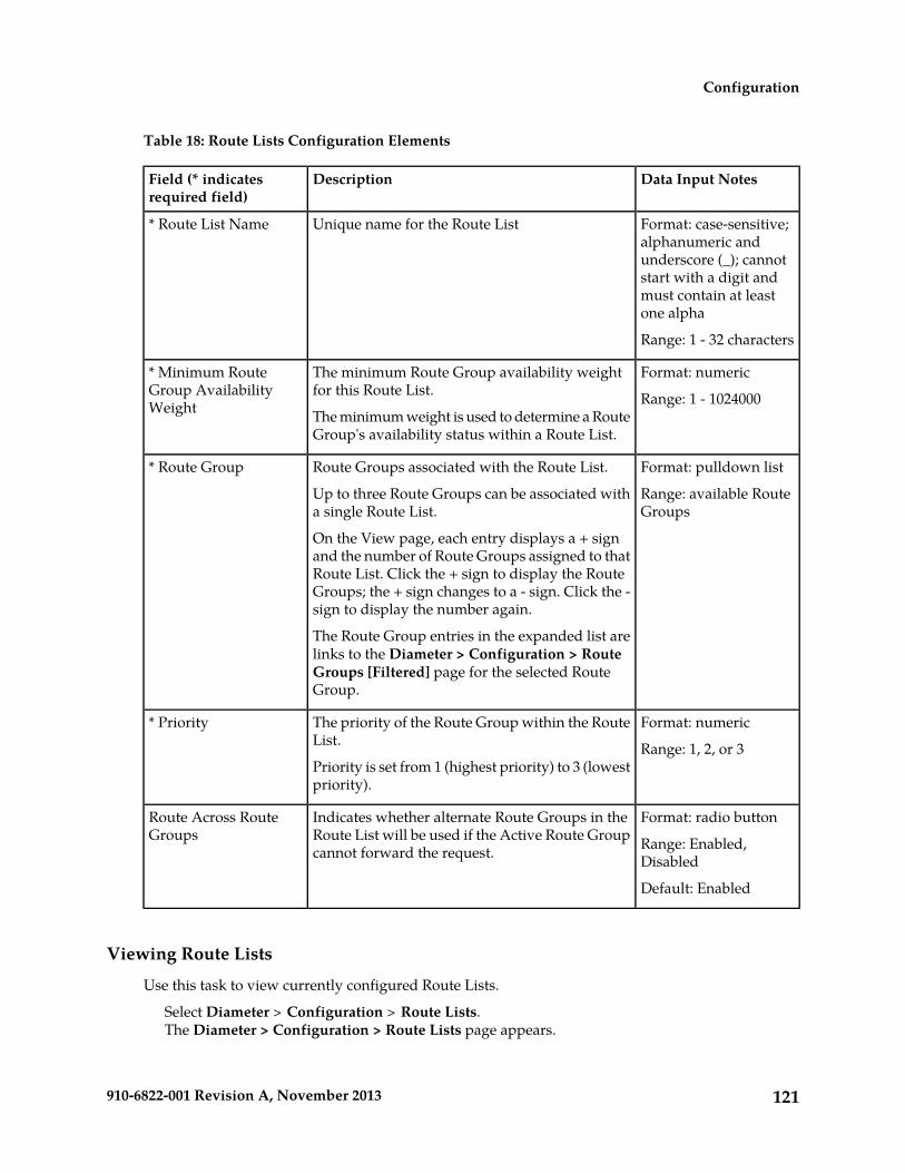
Table 18: Route Lists Configuration Elements
Data Input NotesDescriptionField (* indicatesrequired field)
Format: case-sensitive;alphanumeric and
Unique name for the Route List* Route List Name
underscore (_); cannotstart with a digit andmust contain at leastone alpha
Range: 1 - 32 characters
Format: numericThe minimum Route Group availability weightfor this Route List.
* Minimum RouteGroup AvailabilityWeight Range: 1 - 1024000
The minimum weight is used to determine a RouteGroup's availability status within a Route List.
Format: pulldown listRoute Groups associated with the Route List.* Route Group
Range: available RouteGroups
Up to three Route Groups can be associated witha single Route List.
On the View page, each entry displays a + signand the number of Route Groups assigned to thatRoute List. Click the + sign to display the RouteGroups; the + sign changes to a - sign. Click the -sign to display the number again.
The Route Group entries in the expanded list arelinks to the Diameter > Configuration > RouteGroups [Filtered] page for the selected RouteGroup.
Format: numericThe priority of the Route Group within the RouteList.
* Priority
Range: 1, 2, or 3Priority is set from 1 (highest priority) to 3 (lowestpriority).
Format: radio button
Range: Enabled,Disabled
Indicates whether alternate Route Groups in theRoute List will be used if the Active Route Groupcannot forward the request.
Route Across RouteGroups
Default: Enabled
Viewing Route Lists
Use this task to view currently configured Route Lists.
Select Diameter > Configuration > Route Lists.The Diameter > Configuration > Route Lists page appears.
121910-6822-001 Revision A, November 2013
Configuration
Adding a Route List
Use this task to create a new Route List. The fields are described in Route List configuration elements.
Note: You must have at least one Route Group configured before you can create a Route List.
1. Select Diameter > Configuration > Route Lists.The Diameter > Configuration > Route Lists page appears.
2. Click Insert.The Diameter > Configuration > Route Lists [Insert] page appears.
3. Enter a unique name for the Route List in the Route List Name field.4. Enter the Minimum Route Group Availability Weight in the field.5. Select one to three Route Groups from the Route Group pulldown lists.6. In the corresponding Priority field, set a priority for each selected Route Group.7. Enable or disable routing across alternate Route Groups in Route List by setting Route Across
Route Groups.8. Click:
• OK to save the data and return to the Diameter > Configuration > Route Lists page .• Apply to save the data and remain on this page.• Cancel to return to the Diameter > Configuration > Route Lists page without saving any
changes.
If OK or Apply is clicked and any of the following conditions exist, an error message appears:
• Any required field is empty; no value was entered or selected• The entry in any field in not valid (wrong data type or out of the valid range)• The Route List Name is not unique; it already exists in the system• The selected pulldown list entry no longer exists (has been deleted by another user)• A selected Route Group is a duplicate within the Route List• A Route Group Priority is not unique within the Route List• The maximum number of Route Lists (2000) already exists in the system
Editing a Route List
Use this task to make changes to existing Route Lists.
The Route List Name cannot be changed.
1. Select Diameter > Configuration > Route Lists.The Diameter > Configuration > Route Lists page appears.
2. Select the Route List you want to edit.3. Click Edit.
The Diameter > Configuration > Route Lists [Edit] page appears.
The page is initially populated with the current configured values for the selected Route List.
4. Update the relevant fields.For more information about each field see Route List configuration elements.
122910-6822-001 Revision A, November 2013
Configuration

5. Click:
• OK to save the changes and return to the Diameter > Configuration > Route Lists page.• Apply to save the changes and remain on this page.• Cancel to return to the Diameter > Configuration >Route Lists page without saving any
changes.
If OK or Apply is clicked and any of the following conditions exist, an error message appears:
• Any required field is empty; no value was entered or selected• The entry in any field in not valid (wrong data type or out of the valid range)• The selected Route List no longer exists (has been deleted by another user)• A selected Route Group no longer exists (has been deleted by another user)• A selected Route Group is a duplicate within the Route List• A Route Group Priority is not unique within the Route List
Deleting a Route List
Use this task to delete a Route List.
Note: A Route List cannot be deleted if any of the following conditions are true:
• The Route List is referenced by any Peer Node as the Alternate Implicit Route• The Route List is referenced by any Peer Routing Rule• The Route List is set as the Route List for DAS Node in any Message Copy Configuration Set
1. Select Diameter > Configuration > Route Lists.The Diameter > Configuration > Route Lists page appears.
2. Select the Route List you want to delete.3. Click Delete.
A popup window appears to confirm the delete.4. Click:
• OK to delete the Route List.• Cancel to cancel the delete function and return to the Diameter > Configuration > Route Lists
page.
If OK is clicked and the selected Route List no longer exists (it was deleted by another user), anerror message is displayed and the Route Lists view is refreshed.
Peer Route Tables configuration
A Peer Route Table is a set of prioritized Peer Routing Rules that define routing to Peer Nodes basedon message content.
On the Diameter > Configuration > Peer Route Tables page, you can perform the following actions:
• Filter the list of Peer Route Tables to display only the desired Peer Route Tables.• Sort the list by a column in ascending or descending order, by clicking the column heading. The
default order is by Peer Route Table Name in ascending ASCII order.
123910-6822-001 Revision A, November 2013
Configuration

• Click Insert.
The Diameter > Configuration > Peer Route Tables [Insert] page appears. You can add a newPeer Route Table.
The Diameter > Configuration > Peer Route Tables [Insert] page will not open if
• The maximum number of Peer Route Tables (100) already exists in the system.
• Select a Peer Route Table in the list, and click Edit.
The Diameter > Configuration > Peer Route Tables [Edit] page appears. You can edit the selectedPeer Route Table.
If the selected Peer Route Table has been deleted by another user, the Diameter > Configuration> Peer Route Tables [Edit] page will not open.
• Select a Peer Route Table in the list, and click Delete. You can delete the selected Peer Route Table.
Peer Route Tables elements
Table 19: Peer Route Tables Elements describes the fields on the Peer Route Tables View and Insert pages.Data Input Notes apply only to the Insert page; the View page is read-only.
Table 19: Peer Route Tables Elements
Data Input NotesDescriptionField (* indicatesrequired field)
Format: case-sensitive;alphanumeric andunderscore
Unique name of the Peer Route Table.* Peer Route TableName
Range: 1 - 32 characters;cannot start with a digitand must contain atleast one alpha
The number of Peer Routing Rules in the PeerRoute Table.
Number of Rules
Viewing Peer Route Tables
Use this task to view currently configured Peer Route Tables.
Select Diameter > Configuration > Peer Route Tables.The Diameter > Configuration > Peer Route Tables page appears.
Adding a Peer Route Table
Use this task to create a new Peer Route Table. The fields are described in Peer Route Tables elements.
1. Select Diameter > Configuration > Peer Route Tables.
124910-6822-001 Revision A, November 2013
Configuration

The Diameter > Configuration > Peer Route Tables page appears.2. Click Insert.
The Diameter > Configuration > Peer Route Tables [Insert] page appears.3. Enter a unique name for the Peer Route Table in the Peer Route Table Name field.4. Click:
• OK to save the data and go to the Viewing Rules for Peer Route Table page .• Apply to save the data and remain on this page.• Cancel to return to the Diameter > Configuration > Peer Route Tables page without saving
any changes.
If OK or Apply is clicked and any of the following conditions exist, an error message appears:
• Any required field is empty; no value was entered or selected• The entry in any field in not valid (wrong data type or out of the valid range)• The Peer Route Table Name is not unique; it already exists in the system• The maximum number of Peer Route Tables (100) already exists in the system
After a Peer Route Table is added, Peer Routing Rules can be defined for it. See Peer Routing Rulesconfiguration. For information on the order in which DSR components need to be configured, seeConfiguration Sequence.
Deleting a Peer Route Table
Use this task to delete a Peer Route Table.
Note: A Peer Route Table cannot be deleted if any of the following conditions are true:
• The Peer Route Table is referenced by any Peer Node• The Peer RouteTable is referenced by any Application Id• The selected Peer Route Table is the Default Peer Route Table
1. Select Diameter > Configuration > Peer Route Tables.The Diameter > Configuration > Peer Route Tables page appears.
2. Select the Peer Route Table you want to delete.3. Click Delete.
A popup window appears to confirm the delete.4. Click:
• OK to delete the Peer Route Table.• Cancel to cancel the delete function and return to the Diameter > Configuration > Peer Route
Tables page.
If OK is clicked and the selected Peer Route Table no longer exists (it was deleted by another user),an error message is displayed.
Peer Routing Rules configuration
Peer Routing Rules are prioritized lists of user-configured routing rules that define where to route amessage to upstream Peer Nodes. Routing is based on message content matching a Peer Routing Rule'sconditions. Peer Routing Rules are contained in Peer Route Tables.
125910-6822-001 Revision A, November 2013
Configuration

There are six Peer Routing Rule parameters:
• Destination-Realm• Destination-Host• Application-Id• Command-Code• Origin-Realm• Origin-Host
When a Diameter message matches the conditions of a Peer Routing Rule then the action specified forthe rule will occur. If you choose to route the Diameter message to a Peer Node, the message is sentto a Peer Node in the selected Route List based on the Route Group priority and Peer Node configuredcapacity settings. If you choose to Send an Answer, then the message is not routed and the specifiedDiameter Answer Code is returned to the sender.
Peer Routing Rules are assigned a priority in relation to other Peer Routing Rules. A message will behandled based on the highest priority routing rule that it matches. The lower the number a Peer RoutingRule is assigned the higher priority it will have. (1 is the highest priority and 99 is the lowest priority.)
If a message does not match any of the Peer Routing Rules and the Destination-Host parameter containsa Fully Qualified Domain Name (FQDN) matching a Peer Node, then the message will be directlyrouted to that Peer Node if it has an available Connection. If there is not an available Connection, themessage will be routed using the alternate implicit route configured for the Peer Node.
A Message Copy Configuration Set can be assigned to a Peer Routing Rule, to provide informationfor sending a copy of the message to a DAS.
On the Viewing Rules for Peer Route Table: {Peer Route Table Name} page, you can perform thefollowing actions:
• Filter the list of Rule Names, to display only the desired Rules.
• Sort the list entries in ascending or descending order by column (except Conditions), by clickingthe column heading.
By default, the list is sorted by Priority in ascending ASCII order. The lowest Priority value indicatesthe highest priority. For Rules with the same Priority, the Rule Name is used for sorting.
• Select a blue Route List entry, to open the Diameter > Configuration > Route Lists [Filtered] pagefor the selected entry.
• Click the Insert button.
The Inserting Rule for Peer Route Table: {Peer Route Table Name} page opens. You can add anew Peer Routing Rule and its values. See Adding a Peer Routing Rule.
If the maximum number of Peer Routing Rules (1000) already exists for the Peer Route Table, theInserting Rule for Peer Route Table: {Peer Route Table Name} page will not open, and an errormessage is displayed.
• Select the Rule Name of a Peer Routing Rule in the list, and click the Edit button.
The Editing Rule for Peer Route Table: {Peer Route Table Name} page opens. You can edit theselected Peer Routing Rule. See Editing a Peer Routing Rule.
If the selected Peer Routing Rule has been deleted by another user, the Editing Rule for Peer RouteTable: {Peer Route Table Name} page will not open.
126910-6822-001 Revision A, November 2013
Configuration

• Select the Rule Name of a Peer Routing Rule in the list, and click the Delete button to remove theselected Peer Routing Rule. See Deleting a Peer Route Rule.
Peer Routing Rule configuration elementsTable 20: Peer Routing Rules Configuration Elements describes the fields on the Peer Routing Rules View,Insert, and Edit pages. Data Input Notes only apply to the Insert and Edit pages; the View page isread-only.
Table 20: Peer Routing Rules Configuration Elements
Data Input NotesDescriptionField (* indicatesrequired field)
Format: case-sensitive;alphanumeric and underscore
Unique name of the Peer Routing Rule.* Rule Name
(_); cannot start with a digit andmust contain at least one alpha
Range: 1 - 32 characters
View-onlyThe Peer Route Table to which the PeerRouting Rule belongs
* Peer Route Table
Format: text box; numericPriority of the Rule in relation to other Rules.* Priority
Range: 1 - 99The priority is set from 1 (highest priority) to99 (lowest priority).
In order for a Diameter message to be matched by a Rule, the message mustmatch each specified part of a condition.
* Conditions
Each condition has three parts:
• Parameter• Operator• Value
Format: Operator and Value foreach Parameter
Parameter:
• Destination-Realm• Destination-Host• Application-Id• Command-Code• Origin-Realm• Origin-Host
Format: Pulldown list
Range: See Peer Routing Ruleoperators for a description of
Operator
Sets the relationship between the parameterand the value. For example, if the operator isset to Equals then the Diameter messageparameter must match the set value.
operators available for eachparameter.
127910-6822-001 Revision A, November 2013
Configuration

Data Input NotesDescriptionField (* indicatesrequired field)
Format: text box or pulldown list
Range:
Value
The value in the Diameter message the PeerRouting Rule uses to determine a match. A • Application-ID: available
configured Application IdsValue is required if the Operator is "Equals","Starts With", or "Ends With".
• Command-Code: availableconfigured Command Codes
• Destination-Realm andOrigin-Realm: Realm is acase-insensitive stringconsisting of a list of labelsseparated by dots. A labelmay contain letters, digits,dashes (-), and underscore(_). A label must begin witha letter or underscore andmust end with a letter ordigit. An underscore can beused only as the firstcharacter. A label can be atmost 63 characters long anda realm can be at most 255characters long. You canspecify a substring or acomplete string of a validRealm.
• Destination-Host andOrigin-Host: FQDN is acase-insensitive stringconsisting of a list of labelsseparated by dots. A labelmay contain letters, digits,dashes (-), and underscore(_). A label must begin witha letter or underscore andmust end with a letter ordigit. An underscore can beused only as the firstcharacter. A label can be atmost 63 characters long anda realm can be at most 255characters long. You canspecify a substring or acomplete string of a validFQDN.
128910-6822-001 Revision A, November 2013
Configuration

Data Input NotesDescriptionField (* indicatesrequired field)
Format: selection boxThe action that will happen if the Diametermessage matches the conditions set in the PeerRouting Rule:
Action
Range: Route to Peer, SendAnswer
• Route to Peer: routes a message to a PeerNode using the Route List associated withthis Rule.
Default: Route to Peer
• Send Answer: abandons message routingand sends an answer response that containsthe Diameter answer code associated withthis Rule.
Format: pulldown listRoute List associated with this Rule.Route List
Range: configured Route ListsA Route List is required if the Action is set toRoute to Peer. Default: "-Select-"The Route List entries on the View page arelinks to the Diameter > Configuration > RouteLists [Filtered] page for the selected entry.
Format: pulldown listThe priority to assign to the message. Themessage priority is assigned only when Actionis set to Route to Peer.
Message Priority
Range: No Change, 0, 1, 2. 0 islowest priority
Default: No Change
Format: pulldown listMessage Copy Configuration Set (MCCS) usedfor copying the messages to the DAS. A valid
Message CopyConfiguration Set Range: Default; configured
Message Copy ConfigurationSets
MCCS will mark the messages matched by thisPeer Route Rule for copy to the DAS.
Default: "-Select-"
Format: radio button forpulldown list; radio button fortext box
The answer code associated with this Rule.
A Diameter answer code is required if theAction is set to Send Answer.
AnswerResult-Code Value
Range:
• pulldown list: availableDiameter answer codes
• text box: 1000 - 5999
Default: 3002UNABLE_TO_DELIVER
Format: text box; numeric
Range: 0 - 4294967295
The Vendor Id to place in the Vendor Id AVPof the answer message.
Vendor Id
Format: text box; alphanumeric,underscore (_), period (.)
Value returned in the Error-Message AVP ofthe answer message.
Answer ErrorMessage
129910-6822-001 Revision A, November 2013
Configuration

Data Input NotesDescriptionField (* indicatesrequired field)
Range: 0 - 64 characters
Default: Null string
Peer Routing Rule operatorsTable 21: Peer Routing Rules Operators describes the condition operators available for each parameterin a Peer Routing Rule.
Table 21: Peer Routing Rules Operators
MeaningOperatorParameter
content must equal the value specifiedEqualsDestination-Realm
content must not equal the value specifiedNot Equal
content must start with the value specifiedStarts With
content must end with the value specifiedEnds With
content is not evaluated and the parameter's conditionis always true
Always True
content must equal the value specifiedEqualsDestination-Host
Destination-Host must be present and value must notequal the value specified
Present and Not Equal
content must start with the value specifiedStarts With
content must end with the value specifiedEnds With
Destination-Host must be presentPresent
Destination-Host must be absentAbsent
content is not evaluated and the parameter's conditionis always true
Always True
content must equal the value specifiedEqualsApplication-Id
content must not equal the value specifiedNot Equal
content is not evaluated and the parameter's conditionis always true
Always True
content must equal the value specifiedEqualsCommand-Code
content must not equal the value specifiedNot Equal
content is not evaluated and the parameter's conditionis always true
Always True
content must equal the value specifiedEqualsOrigin-Realm
content must not equal the value specifiedNot Equal
130910-6822-001 Revision A, November 2013
Configuration
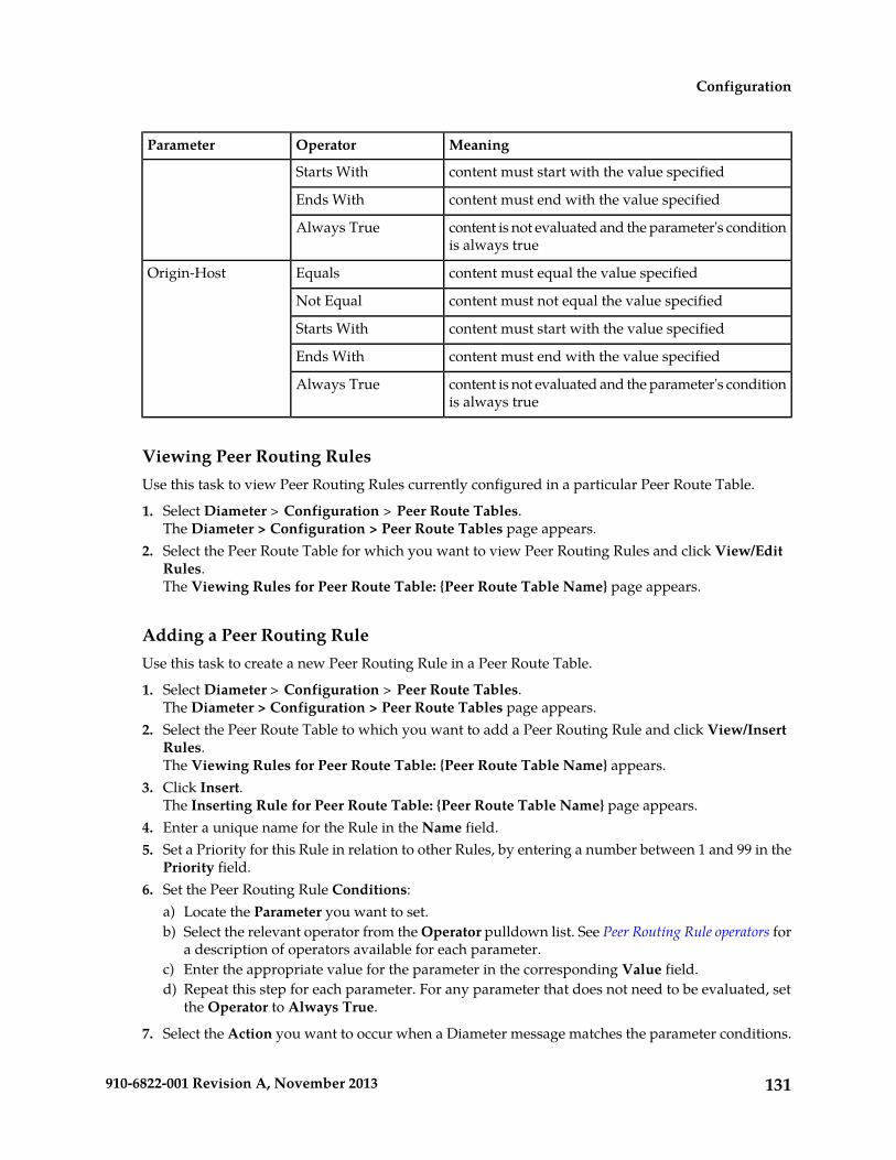
MeaningOperatorParameter
content must start with the value specifiedStarts With
content must end with the value specifiedEnds With
content is not evaluated and the parameter's conditionis always true
Always True
content must equal the value specifiedEqualsOrigin-Host
content must not equal the value specifiedNot Equal
content must start with the value specifiedStarts With
content must end with the value specifiedEnds With
content is not evaluated and the parameter's conditionis always true
Always True
Viewing Peer Routing RulesUse this task to view Peer Routing Rules currently configured in a particular Peer Route Table.
1. Select Diameter > Configuration > Peer Route Tables.The Diameter > Configuration > Peer Route Tables page appears.
2. Select the Peer Route Table for which you want to view Peer Routing Rules and click View/EditRules.The Viewing Rules for Peer Route Table: {Peer Route Table Name} page appears.
Adding a Peer Routing RuleUse this task to create a new Peer Routing Rule in a Peer Route Table.
1. Select Diameter > Configuration > Peer Route Tables.The Diameter > Configuration > Peer Route Tables page appears.
2. Select the Peer Route Table to which you want to add a Peer Routing Rule and click View/InsertRules.The Viewing Rules for Peer Route Table: {Peer Route Table Name} appears.
3. Click Insert.The Inserting Rule for Peer Route Table: {Peer Route Table Name} page appears.
4. Enter a unique name for the Rule in the Name field.5. Set a Priority for this Rule in relation to other Rules, by entering a number between 1 and 99 in the
Priority field.6. Set the Peer Routing Rule Conditions:
a) Locate the Parameter you want to set.b) Select the relevant operator from the Operator pulldown list. See Peer Routing Rule operators for
a description of operators available for each parameter.c) Enter the appropriate value for the parameter in the corresponding Value field.d) Repeat this step for each parameter. For any parameter that does not need to be evaluated, set
the Operator to Always True.
7. Select the Action you want to occur when a Diameter message matches the parameter conditions.
131910-6822-001 Revision A, November 2013
Configuration

• Route to Peer: route the message to a Peer Node using the Route List associated with this Rule.• Send Answer: abandon message routing and send an Answer response containing the Answer
Result-Code Value associated with this Rule.
8. If you selected Route to Peer as the Action, select the Route List to associate with this Rule fromthe pulldown list.
9. If you selected Route to Peer as the Action, select the Message Priority to assign to the message.10. If Diameter Message Copy will be used, select the Message Copy Configuration Set to use when
this Rule is selected for PRT-triggered Message Copy.11. If you selected Send Answer as the Action, select the desired Answer Result-Code Value selection
box:
• Select the pulldown list radio button to use an existing Answer Result-Code; then select anAnswer Result-Code in the list.
• Select the text box radio button, and enter your own Answer Result-Code value.
12. If you selected Send Answer as the Action, enter the desired Vendor Id AVP in the Vendor Idfield.
13. If you selected Send Answer as the Action, enter the desired Error-Message AVP in the AnswerError Message field.
14. Click:
• OK to save the changes and return to the Viewing Rules for Peer Route Table: {Peer RouteTable Name} page.
• Apply to save the changes and remain on this page.• Cancel to return to the Viewing Rules for Peer Route Table: {Peer Route Table Name} page
without saving any changes.
If OK or Apply is clicked and any of the following conditions exist, an error message appears:
• Any required field is empty (no entry was made)• Any field is not valid or is out of range• The Rule Name is not unique; it already exists in the system• The selected Route List no longer exists (has been deleted by another user)• The Rule is similar to an already existing Rule (the same attributes except for Rule Name and
Priority)• The maximum number of Peer Routing Rules (1000) already exists for the Peer Route Table.
Editing a Peer Routing RuleUse this task to edit a Peer Routing Rule in a Peer Route Table.
The Rule Name cannot be changed.
1. Select Diameter > Configuration > Peer Route Tables.The Diameter > Configuration > Peer Route Tables page appears.
2. Select the Peer Route Table which contains the Peer Routing Rule you want to edit and clickView/Edit Rules.The Viewing Rules for Peer Route Table: {Peer Route Table Name} page appears.
3. Select the Peer Routing Rule you want to edit, then click Edit.The Editing Rule for Peer Route Table: {Peer Route Table Name}page appears.
132910-6822-001 Revision A, November 2013
Configuration
4. Update the relevant fields.For more information about each field see Peer Routing Rule configuration elements and Peer RoutingRule operators.
5. Click:
• OK to save the data and return to Viewing Rules for Peer Route Table: {Peer Route TableName} page.
• Apply to save the data and remain on this page.• Cancel to return to the Viewing Rules for Peer Route Table: {Peer Route Table Name} page
without saving any changes.
If OK or Apply is clicked and any of the following conditions exist, an error message appears:
• Any required field is empty (no entry was made)• Any field is not valid or is out of range• The selected Peer Routing Rule no longer exists (was deleted by another user)• The selected Route List no longer exists (was deleted by another user)• The Rule is similar to an already existing Rule (the same attributes except for Rule Name and
Priority)
Deleting a Peer Route RuleUse this task to delete a Peer Routing Rule from a Peer Route Table.
1. Select Diameter > Configuration > Peer Route Tables.The Diameter > Configuration > Peer Route Tables page appears.
2. Select the Peer Route Table which contains the Peer Routing Rule you want to delete and clickView/Edit Rules.The Viewing Rules for Peer Route Table: {Peer Route Table Name} page appears.
3. Select the Peer Routing Rule you want to delete.4. Click Delete.
A popup window appears to confirm the delete.5. Click:
• OK to delete the Peer Routing Rule.• Cancel to cancel the delete function and return to the Viewing Rules for Peer Route Table:
{Peer Route Table Name} page.
If OK is clicked and the selected Peer Routing Rule no longer exists (it was deleted by anotheruser), an error message is displayed and the Peer Routing Rules view is refreshed.
Egress Throttle Groups configuration
Egress Throttle Groups are used to monitor egress Request rate and pending transactions for multiplePeers and Connections across multiple DA-MPs in a DSR.
Egress Throttle Group functions are described in detail in Egress Throttle Groups.
133910-6822-001 Revision A, November 2013
Configuration

Egress Throttle Group Rate Limiting is used to control the total egress Request traffic rate that a DSRwill route to a configured group of Peers or Connections.
Egress Throttle Group Pending Transaction Limiting is used to control the total number of transactionsthat a DSR will allow to be pending for a configured group of Peers or Connections.
The Egress Throttle Group Rate Limiting and Egress Throttle Group Pending Transaction Limitingprovide DSR egress throttling capability that enables:
• A group of Peers and Connections to be associated with an Egress Throttle Group• The maximum egress Request rate of Egress Throttle Groups to be set• The maximum pending transaction limit of Egress Throttle Groups to be set
On the Diameter > Configuration > Egress Throttle Groups page, the following actions can beperformed:
• Filter the list of Egress Throttle Groups to display only the desired Egress Throttle Groups.• Sort the list by a column in ascending or descending order, by clicking the column heading.
All columns except Time of Last Update sort in ascending ASCII order. The Time of Last Updatecolumn sorts by timestamp.
The default order is by Egress Throttle Groups Name in ascending ASCII order.
• Click Insert.
The Diameter > Configuration > Egress Throttle Groups [Insert] page opens. You can add newEgress Throttle Groups.
The Diameter > Configuration > Egress Throttle Groups [Insert] page will not open if the maximumnumber of Egress Throttle Groups (128 per DSR NE) already exists in the system.
• Select an Egress Throttle Group in the list, and click Edit.
The Diameter > Configuration > Egress Throttle Groups [Edit] page opens. You can edit theselected Egress Throttle Group.
If the selected Egress Throttle Group has been deleted by another user, the Diameter > Configuration> Egress Throttle Groups [Edit] page will not open.
• Select an Egress Throttle Group in the list, and click Delete to delete the selected Egress ThrottleGroup.
Egress Throttle Groups elements
Table 22: Egress Throttle Groups Elements describes the fields on the Diameter > Configuration > EgressThrottle Groups page.
Table 22: Egress Throttle Groups Elements
Data Input NotesDescriptionField (* indicates arequired field)
Format: text box;alphanumeric and
A name that uniquely identifies the EgressThrottle Group.
*Egress Throttle GroupName
underscore; must
134910-6822-001 Revision A, November 2013
Configuration

Data Input NotesDescriptionField (* indicates arequired field)
contain at least onealpha and must not startwith a digit.
Range: 1- 32 characters
Format: two checkboxes; one or both boxesmust be checked.
Egress throttlings configurable for this EgressThrottle Group.
Egress Throttlings
Range: Rate Limiting,Pending TransactionLimiting, or both.
Default: both checked.
Members
Format: text box;numeric
Range: 0-128
Peers associated with this Egress Throttle Group.Peers
Format: text box;numeric
Range: 0-128
Connections associated with this Egress ThrottleGroup.
Connections
Rate Limiting
Format: text box;numeric
Range: 100-250000
The maximum allowed Egress Request Rateshared by associated members.
*Maximum EgressRequest Rate
Format: text box;numeric
Range: 2-100
When Egress Request Rate exceeds this percentageof maximum Egress Request Rate, the CongestionLevel is set to 1.
*Onset Threshold Level1 (%)
Default: 100
Format: text box;numeric
Range: 1-100
When Egress Request Rate falls below thispercentage of maximum Egress Request Rate, theCongestion Level is set to 0.
*Abatement ThresholdLevel 1 (%)
Default: 80
Format: text box;numeric
Range: 4-100
When Egress Request Rate exceeds this percentageof maximum Egress Request Rate, the CongestionLevel is set to 2.
Onset Threshold Level2 (%)
135910-6822-001 Revision A, November 2013
Configuration

Data Input NotesDescriptionField (* indicates arequired field)
Format: text box;numeric
Range: 3-100
When Egress Request Rate falls below thispercentage of maximum Egress Request Rate, theCongestion Level is set to 1.
Abatement ThresholdLevel 2 (%)
Format: text box;numeric
Range: 6-100
When Egress Request Rate exceeds this percentageof maximum Egress Request Rate, the CongestionLevel is set to 3.
Onset Threshold Level3 (%)
Format: text box;numeric
Range: 5-100
When Egress Request Rate falls below thispercentage of maximum Egress Request Rate, theCongestion Level is set to 2.
Abatement ThresholdLevel 3 (%)
Format: text box;numeric
Range: 20-90
Percentage contribution of the current EgressRequest Rate sample to the Smoothed EgressRequest Rate.
*Smoothing Factor (%)
Default: 80
Format: text box;numeric
Range: 200-10000
The amount of time in milliseconds that theSmoothed Egress Request Rate must remain belowan abatement threshold before the CongestionLevel is lowered.
*Abatement Time(msec)
Default: 500
Pending Transaction Limiting
Format: text box;numeric
The maximum allowed Egress PendingTransactions for the Peers and Connections withina group.
*Maximum EgressPending Transactions
Range: 100-1000000
Format: text box;numeric
When Egress Pending Transactions exceeds thispercentage of maximum Egress PendingTransactions, the Congestion Level is set to 1.
*Onset Threshold Level1 (%)
Range: 2-100
Default: 100
Format: text box;numeric
When Egress Pending Transactions falls belowthis percentage of maximum Egress PendingTransactions, the Congestion Level is set to 0.
*Abatement ThresholdLevel 1 (%)
Range: 1-100
Default: 80
Format: text box;numeric
When Egress Pending Transactions exceeds thispercentage of maximum Egress PendingTransactions, the Congestion Level is set to 2.
Onset Threshold Level2 (%)
Range: 4-100
136910-6822-001 Revision A, November 2013
Configuration

Data Input NotesDescriptionField (* indicates arequired field)
Format: text box;numeric
When Egress Pending Transactions falls belowthis percentage of maximum Egress PendingTransactions, the Congestion Level is set to 1.
Abatement ThresholdLevel 2 (%)
Range: 3-100
Format: text box;numeric
When Egress Pending Transactions exceeds thispercentage of maximum Egress PendingTransactions, the Congestion Level is set to 3.
Onset Threshold Level3 (%)
Range: 6-100
Format: text box;numeric
When Egress Pending Transactions falls belowthis percentage of maximum Egress PendingTransactions, the Congestion Level is set to 2.
Abatement ThresholdLevel 3 (%)
Range: 5-100
Format: text box;numeric
The amount of time in milliseconds that EgressPending Transactions must remain below an
*Abatement Time(msec)
abatement threshold before the Congestion Levelis lowered. Range: 200-10000
Default: 500
Viewing Egress Throttle Groups
Use this task to view Egress Throttle Groups.
Egress Throttle Groups fields are described in Egress Throttle Groups elements.
Select Diameter > Configuration > Egress Throttle Groups.The Diameter > Configuration> Egress Throttle Groups page appears.
Adding Egress Throttle Groups
Use this task to create new Egress Throttle Groups.
Egress Throttle Groups fields are described in Egress Throttle Groups elements.
1. Select Diameter > Configuration > Egress Throttle Groups.The Diameter > Configuration > Egress Throttle Groups page appears.
2. Click Insert.The Diameter > Configuration > Egress Throttle Groups [Insert] page appears.
3. Enter a unique name for the Egress Throttle Group in the Egress Throttle Group Name field.4. Select either or both of the Egress Throttlings choices for this Egress Throttle Group by checking
one or both boxes to the right of the Egress Throttlings field. One or both boxes must be selectedfor all Egress Throttling Groups, as follows:a) To control the total egress Request traffic rate that a DSR will route to a user-defined group of
Connections or Peers associated with this Egress Throttle Group, check the Rate Limiting box.b) To control the total number of transactions that a DSR will allow to be pending for a user-defined
group of Connections or Peers associated with this Egress Throttle Group, check the PendingTransactions Limiting box.
137910-6822-001 Revision A, November 2013
Configuration

5. Under the Members tab, enter values for the following fields:a) Peers
Use the pulldown list to select from a list of Peer names, clicking the Add button after eachselection. Use the X to the right of the pulldown list to remove a selection.
b) ConnectionsUse the pulldown list to select from a list of Connection names, clicking the Add button aftereach selection. Use the X to the right of the pulldown list to remove a selection.
6. If the Rate Limiting chedk box for Egress Throttlings is checked for this Egress Throttle Group,enter values for the required fields and for optional fields, as needed.
7. If the Pending Transactions Limiting check box for Egress Throttlings is checked for this EgressThrottle Group, enter values for the required fields and for optional fields, as needed.
8. Click:
• OK to save the changes and return to the Diameter > Configuration > Egress Throttle Groupspage.
• Apply to save the changes and remain on this page.• Cancel to return to the Diameter > Configuration > Egress Throttle Groups page without
saving any changes.
If OK or Apply is clicked and any of the following conditions exist, an error message appears:
• The maximum number of Egress Throttle Groups have already been created.• There is no Peer Node or Connection in the signaling network element corresponding to the
Egress Throttle Group to be added.• Any required fields are left empty.• An Egress Throttle Group is configured with the greater than the maximum total number of
Peers and Connections.• An Egress Throttle Group is configured with duplicate Peers or Connections.• An Egress Throttle Group is configured with thresholds at level 3 set but thresholds at level 2
are missing.• An Egress Throttle Group is configured with Onset Thresholds at a congestion level 2 or level
3 without providing corresponding Abatement Thresholds.• An Egress Throttle Group is configured with Abatement Thresholds at a congestion level 2 or
level 3 without providing corresponding Onset Thresholds.• An Egress Throttle Group is configured with Onset Threshold at a congestion level lesser than
the corresponding Abatement Threshold level at the same level.• An Egress Throttle Group is configured with Onset Threshold at a congestion level greater than
the corresponding Abatement Threshold at the succeeding level• An Egress Throttle Group is configured with a Peer already configured as a member in any
Egress Throttle Group. (Explicit association of Peer with another Egress Throttle Group)• An Egress Throttle Group is configured with a Peer which is associated with a Connection
configured as a member in any Egress Throttle Group. (Implicit association of Peer with anotherEgress Throttle Group)
• An Egress Throttle Group is configured with a Connection already configured as a member inany Egress Throttle Group. (Explicit association of Connection with another Egress ThrottleGroup)
• An Egress Throttle Group is configured with a Connection which is associated with a Peerconfigured as a member in any Egress Throttle Group. (Implicit association of Connection withanother Egress Throttle Group)
138910-6822-001 Revision A, November 2013
Configuration

• An Egress Throttle Group is configured with a Connection and a Peer associated with eachother.
Editing Egress Throttle Groups
Use this task to edit Egress Throttle Groups.
When the Diameter > Configuration > Egress Throttle Groups [Edit] page opens, the columns areinitially populated with the current configuration of the selected Egress Throttle Group.
The existing Egress Throttle Groups Name cannot be changed.
Changes can be made to an Egress Throttle Group configuration with either Rate Limiting AdminState or Pending Transaction Limiting Admin State in the Enabled or the Disabled state.
Changes can be made to an Egress Throttle Group configuration irrespective of the Operational Statusof the associated Peer Connections.
Egress Throttle Groups fields are described in Egress Throttle Groups elements.
1. Select Diameter > Configuration > Egress Throttle Groups.The Diameter > Configuration > Egress Throttle Groups page appears.
2. Select the Egress Throttle Groups to be edited, then click Edit.
The Diameter > Configuration > Egress Throttle Groups [Edit] page appears.
3. Update the relevant fields.
An entry in a pulldown list can be removed by selecting the entry in the list, and then clicking theX to the right of the pulldown list.
4. Click:
• OK to save the changes and return to the Diameter > Configuration > Egress Throttle Groupspage.
• Apply to save the changes and remain on this page.• Cancel to return to the Diameter > Configuration > Egress Throttle Groups page without
saving any changes.
If OK or Apply is clicked and any of the following conditions exist, an error message appears:
• An attempt is made to remove the Rate Limiting Egress Throttling by removing the check fromthe corresponding Egress Throttlings check box for an Egress Throttle Group for which theRate Limiting Admin State is set to Enabled.
• An attempt is made to remove Pending Transaction Egress Throttling by removing the checkfrom the corresponding Egress Throttlings check box for an Egress Throttle Group for whichthe Pending Transaction Limiting Admin State is set to Enabled.
Deleting Egress Throttle Groups
Use this task to delete Egress Throttle Groups.
An Egress Throttle Group cannot be deleted if either its corresponding Rate Limiting Admin State orPending Transaction Limiting Admin State is not in the Disabled admin state. Before you perform
139910-6822-001 Revision A, November 2013
Configuration

this task, ensure that the Rate Limiting Admin State or Pending Transaction Limiting Admin State forthe Egress Throttle Group is in the Disabled admin state.
1. Select Diameter > Configuration > Egress Throttle GroupsThe Diameter > Configuration > Egress Throttle Groups page appears.
2. Select the Egress Throttle Group to be deleted.3. Click Delete.
A popup window appears to confirm the delete.4. Click:
• OK to delete the Egress Throttle Group.• Cancel to cancel the delete function and return to the Diameter > Configuration > Egress
Throttle Groups page.
If OK is clicked and the following condition exists, an error message appears:
• The Egress Throttle Group Rate Limiting Admin State for the Egress Throttle Group to be deletedis not in the Disabled admin state.
• The Egress Throttle Group Pending Transaction Limiting Admin State for the Egress ThrottleGroup to be deleted is not in the Disabled admin state.
Reroute On Answer configuration
Using Reroute On Answer, you can configure rerouting scenarios based on the Application Id andResult-Code AVP values in Answer messages. If these values match the configured order pair ofApplication Id and Result-Code AVP value, the message is rerouted to another available Peer Nodefrom the Route Group selected during the routing process.
If there are no additional available Peer Nodes in the selected Route Group, or the maximum numberof transmits has been met, then reroute is not attempted and the Answer is sent back to the originator.
On the Diameter > Configuration > Reroute on Answer page, you can perform the following actions:
• Filter the list to display only the desired entries.• Sort the list by column in ascending or descending order, by clicking the column heading. The
default order is by Answer Result Code-AVP Value in ascending ASCII order.• Click Insert.
The Diameter > Configuration > Reroute on Answer [Insert] page appears. You can add a newentry.
The Diameter > Configuration > Reroute on Answer [Insert] will not open if the maximum numberof Reroute on Answer entries (1000) already exists in the system.
• Select a Reroute on Answer entry, and click Delete to delete the selected entry.
Reroute On Answer configuration elements
Table 23: Reroute On Answer Configuration Elements describes the fields on the Reroute On Answer Viewand Insert pages. Data Input Notes apply only to the Insert page; the View page is read-only.
140910-6822-001 Revision A, November 2013
Configuration

Table 23: Reroute On Answer Configuration Elements
Data Input NotesDescriptionField (* indicatesrequired field)
Format: numericValue in the result-code AVP of the Answermessage.
* Answer Result-CodeAVP Value Range: 0 - 4294967295
Format: radio buttons,text box, and pulldownlist
Application ID in the Answer message thatidentifies a Diameter Application. It is commonlyused for screening and routing messages betweenDiameter nodes.
The Internet Assigned Numbers Authority listsstandard and vendor-specific Application IDs ontheir iana.org website. On the website:
Application Id
Range:
• first radio button:ALL
• second radio button:pulldown list with• Select Protocol AssignmentsavailableApplication Ids
• Scroll to locate the Authentication,Authorization, and Accounting (AAA)Parameters heading Default: ALL
• Select Application IDs under the heading
Viewing Reroute On Answer
Use this task to view Reroute On Answer.
Select Diameter > Configuration > Reroute On Answer.The Diameter > Configuration > Reroute on Answer page appears.
Adding a Reroute On Answer entry
Use this task to create a new Reroute On Answer entry.
The fields are described in Reroute On Answer configuration elements.
1. Select Diameter > Configuration > Reroute On Answer.The Diameter > Configuration > Reroute on Answer page appears.
2. Click Insert.The Diameter > Configuration > Reroute On Answer [Insert] page appears.
3. Enter the desired Result-Code AVP in the Answer Result-Code AVP Value field.4. Perform one of the following actions for Application Id:
• Select ALL to apply the Reroute On Answer entry to all Application Ids.• Select the second radio button, and select the appropriate Application Id from the pulldown
list.
5. Click:
• OK to save the changes and return to the Diameter > Configuration > Reroute on Answerpage.
141910-6822-001 Revision A, November 2013
Configuration
• Apply to save the changes and remain on this page.• Cancel to return to the Diameter > Configuration > Reroute on Answer page without saving
any changes.
If OK or Apply is clicked and any of the following conditions exist, an error message appears:
• A field is empty; a value was not entered• A value is not valid• The Answer Result-Code AVP Value and Application Id combination is not unique; it already
exists in the system• Adding the new Reroute on Answer entry would cause the maximum number of Reroute on
Answer entries (1000) to be exceeded
Deleting a Reroute On Answer
Use this task to delete a Reroute On Answer entry.
1. Select Diameter > Configuration > Reroute On Answer.The Diameter > Configuration > Reroute On Answer page appears.
2. Select the Answer Result-Code AVP Value for the Reroute On Answer you want to delete.A popup window appears to confirm the delete.
3. Click Delete.4. Click:
• OK to delete the Reroute on Answer entry.• Cancel to cancel the delete function and return to the Diameter > Configuration > Reroute On
Answer page.
If OK is clicked and the selected entry no longer exists (it was deleted by another user), an errormessage is displayed and the Reroute on Answer page is refreshed.
Application Route Tables configuration
An Application Route Table contains one or more Application Routing Rules that can be used forrouting Request messages to DSR Applications.
On the Diameter > Configuration > Application Route Tables page, you can perform the followingactions:
• Filter the list of Application Route Tables to display only the desired Application Route Tables.• Sort the list in ascending or descending order by clicking a column heading. The default order is
by Application Route Table Name in ascending ASCII order.• Click Insert.
The Diameter > Configuration > Application Route Tables [Insert] page appears. You can adda new Application Route Table.
The Diameter > Configuration > Application Route Tables [Insert] page will not open if themaximum number of Application Route Tables (100) already exists in the system.
142910-6822-001 Revision A, November 2013
Configuration

• Select an Application Route Table in the list, and click Delete. You can delete the selectedApplication Route Table.
• Select an Application Route Table in the list, and click View/Edit Rules.
The Diameter > Configuration > Application Route Tables [View/Edit Rules] page appears. Youcan edit the selected Application Route Table Rules.
If the selected Application Route Table has been deleted by another user, the Diameter >Configuration > Application Route Tables [View/Edit Rules] page will not open.
Application Route Tables elements
Table 24: Application Route Tables elements describes the fields on the Application Route Tables Viewand Insert pages. Data Input Notes apply only to the Insert page; the View page is read-only.
Table 24: Application Route Tables elements
Data Input NotesDescriptionField (* indicatesrequired field)
Format: text box;alphanumeric and
Unique name of the Application Route Table.* Application RouteTable Name
underscore (_); cannotstart with a digit andmust contain at leastone alpha
Range: 1 - 32 characters
Viewing Application Route Tables
Use this task to view currently configured Application Route Tables. The fields are described inApplication Route Tables elements
Select Diameter > Configuration > Application Route Tables.The Diameter > Configuration > Application Route Tables page appears.
Adding an Application Route Table
Use this task to create a new Application Route Table. The fields are described in Application RouteTables elements.
1. Select Diameter > Configuration > Application Route Tables.The Diameter > Configuration > Application Route Tables page appears.
2. Click Insert.The Diameter > Configuration > Application Route Tables [Insert] page appears.
3. Enter a unique name for the Application Route Table in the Application Route Table Name field.4. Click:
143910-6822-001 Revision A, November 2013
Configuration
• OK to save the new Application Route Table and go to the Diameter > Configuration >Application Route Tables page .
• Apply to save the new Application Route Table and remain on this page.• Cancel to return to the Diameter > Configuration > Application Route Tables page without
saving any changes.
If OK or Apply is clicked and any of the following conditions exist, an error message appears:
• Any required field is empty; no value was entered or selected• The entry in any field in not valid (wrong data type or out of the valid range)• The Application Route Table Name is not unique; it already exists in the system• Adding this Application Route Table would cause the maximum number of Application Route
Tables (100) allowed in the system to be exceeded• Adding this Application Route Table would cause the maximum number of Application Routing
Rules (1000) allowed in the system to be exceeded
After an Application Route Table is added, Application Routing Rules can be defined for it. SeeApplication Routing Rules configuration.
Deleting an Application Route Table
Use this task to delete an Application Route Table.
Note: A Peer Route Table cannot be deleted if any of the following conditions are true:
• The Peer Route Table is referenced by any Peer Node• The Peer RouteTable is referenced by any Application Id• The selected Peer Route Table is the Default Peer Route Table
1. Select Diameter > Configuration > Application Route Tables.The Diameter > Configuration > Application Route Tables page appears.
2. Select the Application Route Table you want to delete.3. Click Delete.
A popup window appears to confirm the delete.4. Click:
• OK to delete the Application Route Table.• Cancel to cancel the delete function and return to the Diameter > Configuration > Application
Route Tables page.
If OK is clicked and the selected Application Route Table no longer exists (it was deleted byanother user), an error message is displayed.
Application Routing Rules configuration
An Application Routing Rule defines message routing to a DSR Application based on message contentmatching the Application Routing Rule's conditions. There are six Application Routing Rule parameters:
• Destination-Realm• Destination-Host• Application-Id
144910-6822-001 Revision A, November 2013
Configuration

• Command-Code• Origin-Realm• Origin-Host
When a Diameter message matches the conditions of an Application Routing Rule then message isrouted to the DSR Application specified in the rule.
Application Routing Rules are assigned a priority in relation to other Application Routing Rules. Amessage will be handled based on the highest priority routing rule that it matches. The lower thenumber an Application Routing Rule is assigned the higher priority it will have. (1 is highest priorityand 99 is lowest priority.)
One or more DSR Applications must be activated before Application Routing Rules can be configured.
On the Viewing Rules for Application Route Table: {Application Route Table Name} page, you canperform the following actions:
• Filter the list of Rule Names, to display only the desired Rules.• Sort the list entries in ascending or descending order by Rule Name, Priority, or Application Name,
by clicking the column heading.
By default, the list is sorted by Priority in ascending ASCII order. The lowest Priority value indicatesthe highest priority. For Rules with the same Priority, the Rule Name is used for sorting.
• Click the Insert button.
The Inserting Rule for Application Route Table: {Application Route Table Name} page opens.You can add a new Application Routing Rule and its values. See Adding an Application Routing Rule.If the maximum number of Application Routing Rules (1000) already exists in the system, theInserting Rule for Application Route Table: {Application Route Table Name} page will not open,and an error message is displayed.
• Select the Rule Name of an Application Routing Rule in the list, and click the Edit button.
The Editing Rule for Application Route Table: {Application Route Table Name} page opens. Youcan edit the selected Application Routing Rule. See Editing an Application Routing Rule.
• Select the Rule Name of an Application Routing Rule in the list, and click the Delete button toremove the selected Application Routing Rule. See Deleting an Application Routing Rule
Application Routing Rule configuration elementsTable 25: Application Routing Rules Configuration Elements describes the fields on the Application RoutingRules View, Insert, and Edit pages. Data Input Notes apply only to the Insert and Edit pages; the Viewpage is read-only.
Table 25: Application Routing Rules Configuration Elements
Data Input NotesDescriptionField (* indicatesrequired field)
Format: text box;case-sensitive;
Name of the Application Routing Rule. The Namemust be unique.
* Rule Name
alphanumeric andunderscore (_); cannotstart with a digit and
145910-6822-001 Revision A, November 2013
Configuration

Data Input NotesDescriptionField (* indicatesrequired field)
must contain at leastone alpha (A-Z, a-z)
Range: 1 - 32 characters
View OnlyApplication Route Table associated with this Rule.* Application RouteTable
Format: text box;numeric
Priority of the Rule in relation to other Rules.
The lower the Priority number, the higher aPriority a Application Routing Rule will have.
* Priority
Range: 1 - 99That is, the Application Routing Rule with aPriority set to 1 has first priority, the ApplicationRouting Rule with a Priority set to 2 has secondpriority, and so on.
Conditions associated with this Rule.* Conditions
Each condition has three parts:
• Parameter• Operator• Value
Format: Operator andValue for eachParameter
Parameter:
• Destination-Realm• Destination-Host• Application-ID• Command-Code• Origin-Realm• Origin-Host
Format: Pulldown listOperator
Range: See ApplicationRouting Rule operators
Sets the relationship between the Parameter andthe Value. For example, if the Operator is set toEquals then the Diameter message Parameter mustmatch the set Value.
for a description ofoperators available foreach parameter.
Default: "-Select-"
Format: text box orpulldown list
Value
The value in the Diameter message that theApplication Routing Rule uses to determine amatch.
• Destination-Realmand Origin-Realm:text box;The Value field is required when the Operator is
"Equals", "Starts With", and "Ends With". case-insensitivestring consisting of alist of labels
146910-6822-001 Revision A, November 2013
Configuration

Data Input NotesDescriptionField (* indicatesrequired field)
The Value field is disabled for the Operators"Present", "Absent", and "Always True".
separated by dots,where a label maycontain letters,digits, dashes ('-')and underscore ('_').A label must startwith a letter, digit orunderscore and mustend with a letter ordigit. Underscoresmay be used only asthe first character. Alabel can be at most63 characters longand a Realm cab beat most 255characters long.
• Destination-Hostand Origin-Host(FQDN): text box;case-insensitivestring consisting of alist of labelsseparated by dots,where a label maycontain letters,digits, dashes ('-')and underscore ('_').A label must startwith a letter, digit orunderscore and mustend with a letter ordigit. Underscoresmay be used only asthe first character. Alabel can be at most63 characters longand a FQDN can beat most 255characters long.
• Application-ID:pulldown list ofconfiguredApplication Ids
• Command-Code:pulldown list ofconfiguredCommand Codes
147910-6822-001 Revision A, November 2013
Configuration

Data Input NotesDescriptionField (* indicatesrequired field)
Range: One or moreParameters withOperator and Value foreach Parameter
Default forApplication-Id andCommand Code:"-Select-"
Format: pulldown listDSR Application Name associated with this Rule.* Application Name
Range: All activatedDSR Applications
Default: "-Select-"
Application Routing Rule operatorsTable 26: Application Routing Rules Operators describes the Conditions operators available for eachparameter in a Application Routing Rule.
Table 26: Application Routing Rules Operators
MeaningOperatorParameter
content must equal the value specifiedEqualsDestination-Realm
content must not equal the value specifiedNot Equal
content must start with the value specifiedStarts With
content must end with the value specifiedEnds With
content is not evaluated and the parameter's conditionis always true
Always True
content must equal the value specifiedEqualsDestination-Host
Destination-Host must be present and value must notequal the value specified
Present and Not Equal
content must start with the value specifiedStarts With
content must end with the value specifiedEnds With
Destination-Host must be presentPresent
Destination-Host must be absentAbsent
content is not evaluated and the parameter's conditionis always true
Always True
content must equal the value specifiedEqualsApplication-Id
148910-6822-001 Revision A, November 2013
Configuration

MeaningOperatorParameter
content must not equal the value specifiedNot Equal
content is not evaluated and the parameter's conditionis always true
Always True
content must equal the value specifiedEqualsCommand-Code
content must not equal the value specifiedNot Equal
content is not evaluated and the parameter's conditionis always true
Always True
content must equal the value specifiedEqualsOrigin-Realm
content must not equal the value specifiedNot Equal
content must start with the value specifiedStarts With
content must end with the value specifiedEnds With
content is not evaluated and the parameter's conditionis always true
Always True
content must equal the value specifiedEqualsOrigin-Host
content must not equal the value specifiedNot Equal
content must start with the value specifiedStarts With
content must end with the value specifiedEnds With
content is not evaluated and the parameter's conditionis always true
Always True
Viewing Application Routing RulesThe use of Application Routing Rules is described in Application Routing Rules configuration.
The fields are described in Application Routing Rule configuration elements.
To view currently configured Application Routing Rules in a selected Application Route Table,
1. Select Diameter > Configuration > Application Route Tables.The Diameter > Configuration > Application Route Tables page appears with a list of configuredApplication Route Tables.
2. Select an Application Route Table Name in the list.3. Click View/Edit Rules.
The Viewing Rules for Application Route Table: {Application Route Table Name} page opens,with a list of the Rules that are currently configured in the selected Application Route Table.
Adding an Application Routing RuleUse this procedure to create a new Application Routing Rule in a selected Application Route Table.The fields are described in Application Routing Rule configuration elements.
149910-6822-001 Revision A, November 2013
Configuration

1. Select Diameter > Configuration > Application Route Tables.
The Diameter > Configuration > Application Routie Tables page appears.
2. Select an Application Route Table Name in the list.3. Click View/Edit Rules.
The Viewing Rules for Application Route Table: {Application Route Table Name} page appears.
4. Click Insert.The Inserting Rule for Application Route Table: {Application Route Table Name} page appears.
If the maximum number of Application Routing Rules (1000) already exists in the system, theDiameter > Configuration > Application Routing Rules [Insert] page will not open.
5. Enter a unique name for the Rule in the Rule Name field.6. Set a Priority for this Rule in relation to other Rules, by entering a number between 1 and 99 in the
Priority field.7. Set the Application Routing Rule Conditions:
a) Locate the Parameter you want to set.b) Select the relevant operator from the Operator pulldown list.
See Application Routing Rule operators for a description of operators available for each Parameter.c) Enter the appropriate value for the Parameter in the corresponding Value field.
The Value text box is disabled for some Operators that do not require a value.d) Repeat this step for each Parameter. For any Parameter that does not need to be evaluated, set
the Operator to Always True.
8. From the pulldown list, select the DSR Application Name associated with this Rule.9. Click:
• OK to save the Rule and return to the Diameter > Configuration > Application Routing Rulespage.
• Apply to save the Rule and remain on this page.• Cancel to return to the Viewing Rules for Application Route Table: {Application Route Table
Name} page without saving any changes.
If OK or Apply is clicked and any of the following conditions exist, an error message appears:
• Any required field is empty (no entry was made)• Any field is not valid or is out of range• The Rule Name is not unique• The Rule is similar to an already existing Rule (the same attributes except for Rule Name and
Priority)• Adding the Application Routing Rule would cause the maximum number of Application Routing
Rules (1000) allowed in the system to be exceeded
For Application Route Tables that are associated with Application Ids, a warning appears for anattempt to add an Application Routing Rule with an Application-Id that does not match theApplication Id with which the Application Route Table is associated.
150910-6822-001 Revision A, November 2013
Configuration

Editing an Application Routing RuleUse this task to edit an Application Routing Rule in a selected Application Route Table.
Note: The Rule Name field cannot be edited.
1. Select Diameter > Configuration > Application Route Tables.
The Diameter > Configuration > Application Routie Tables page appears.
2. Select an Application Route Table Name in the list.3. Click View/Edit Rules.
The Viewing Rules for Application Route Table: {Application Route Table Name} page appears.
4. Select a Rule to edit.5. Click Edit.
The Editing Rule for Application Route Table: {Application Route Table Name} page appears.
6. Update the relevant fields.For more information about each field see Application Routing Rule configuration elements andApplication Routing Rule operators.
7. Click:
• OK to save the changes and return to the Viewing Rules for Application Route Table:{Application Route Table Name} page.
• Apply to save the changes and remain on this page.• Cancel to return to the Viewing Rules for Application Route Table: {Application Route Table
Name} page without saving any changes.
If OK or Apply is clicked and any of the following conditions exist, an error message appears:
• The selected Application Routing Rule no longer exists; it has been deleted by another user• Any required field is empty (no entry was made)• Any field is not valid or is out of range• The Rule is similar to an already existing Rule (the same attributes except for Rule Name and
Priority)
Deleting an Application Routing RuleUse this task to delete an Application Routing Rule from a selected Application Route Table.
1. Select Diameter > Configuration > Application Route Tables.The Diameter > Configuration > Application Route Tables page appears with a list of configuredApplication Route Tables.
2. Select an Application Route Table Name in the list.3. Click View/Edit Rules.
The Viewing Rules for Application Route Table: {Application Route Table Name} page opens,with a list of the Rules that are currently configured in the selected Application Route Table.
4. Select the Application Routing Rule you want to delete, then click Delete.A popup window appears.
151910-6822-001 Revision A, November 2013
Configuration

5. Perform one of the following actions:
• Click OK to delete the Application Routing Rule.• Click Cancel to cancel the delete function and return to the Viewing Rules for Application
Route Table: {Application Route Table Name} page.
If OK is clicked and the selected Application Routing Rule no longer exists (it was deleted byanother user), an error message is displayed and the Application Routing Rules view is refreshed.
Routing Option Sets configuration
A Routing Option Set is a collection of Routing Options that are used when a Request message isreceived to control the number of times an application can forward the request message and howcertain delivery error situations are handled.
A Routing Option Set can be associated with the Peer Node that the Request is received from, or withthe Diameter Application Id contained in the Request message header. If Routing Option Sets areassociated with both the Peer Node and the Application Id, the one associated with the Peer Nodetakes precedence. If neither the Peer Node nor the Application Id have an associated Routing OptionSet, then the Default Routing Option Set is used.
On the Diameter > Configuration > Routing Option Sets page, you can perform the following actions:
• Filter the list of Routing Option Sets to display only the desired Routing Option Sets.• Sort the list by a column in ascending or descending order, by clicking the column heading. The
default order is by Routing Option Set Name in ascending ASCII order.• Click Insert.
The Diameter > Configuration > Routing Option Sets [Insert] page appears. You can add a newRouting Option Set.
The Diameter > Configuration > Routing Option Sets [Insert] page will not open if the maximumnumber of Routing Option Sets (20) already exists in the system
• Select a Routing Option Set in the list, and click Edit.
The Diameter > Configuration > Routing Option Sets [Edit] page appears. You can edit theselected Routing Option Set.
If the selected Routing Option Set has been deleted by another user, the Diameter > Configuration> Routing Option Sets [Edit] page will not open.
• Select a Routing Options Set in the list, and click Delete. You can delete the selected Routing OptionSet. The Default Routing Option Set cannot be deleted.
Routing Option Sets elements
Table 27: Routing Option Sets Elements describes the fields on the Routing Option Sets View, Insert, andEdit pages. Data Input Notes apply only to the Insert and Edit pages; the View page is read-only.
152910-6822-001 Revision A, November 2013
Configuration

Table 27: Routing Option Sets Elements
Data Input NotesDescriptionField (* indicatesrequired field)
Format: text box;case-sensitive;
Unique name of the Routing Option Set.* Routing Option SetName
alphanumeric andunderscore
Range: 1 - 32 characters;cannot start with a digitand must contain atleast one alpha
Format: text box;numeric
Maximum number of times an application isallowed to forward a Request message.
* Maximum PerMessage ForwardingAllowed Range: 1 - 5
Default: 1
Format: text box;numeric
The total time DSR allows to forward a Request,including initial and all subsequent routingattempts.
Transaction Lifetime
Range: 100 - 540000 ms
Default: 1000 ms
Format: pulldown listPending Answer Timer of this Routing OptionSet
Pending Answer Timer
Range: Default,configured PendingAnswer Timers
If the Pending Answer Timer value is "NotSelected", the egress Peer Node's associatedPending Answer Timer, if it is defined, will beused when processing transactions. Default: "Not Selected."
A Pending Answer Timer cannot be assigned tothe Default Routing Option Set.
Format: pulldown listAction taken by DSR when a Request cannot beprocessed due to an internal resource beingexhausted
* Resource ExhaustedAction Range: Abandon with
no Answer; SendAnswer
Default: Abandon withno Answer
Format: radio button forpulldown list, radiobutton for text box
Value to be placed in the Result-Code AVP of theAnswer message. An Answer Result-Code valueis required if Resource Exhausted Action is 'SendAnswer'
Resource ExhaustedAnswer Result-Code
Range: 1000 - 5999
Select the code from thepulldown list or enterthe code in the text box.
153910-6822-001 Revision A, November 2013
Configuration

Data Input NotesDescriptionField (* indicatesrequired field)
Default: "3004TOO_BUSY" inpulldown list
Format: text box;alphanumeric
String to be placed in the Error-Message AVP ofthe Answer message for Resource Exhaustion
Resource ExhaustedAnswer Error Message
Range: 0 - 64 characters
Format: text box;numeric
Range: 1 - 4294967295
Resource Exhausted Vendor-Id Value. Whenspecified, the Answer generated will be anExperimental-Result-Code grouped AVP with thespecified Vendor-Id value placed in the Vendor-IdAVP.
Resource ExhaustedVendor Id
Format: pulldown listAction taken by DSR when the routing of aRequest is abandoned or the time to route exceedsthe Transaction Lifetime
* No Peer ResponseAction Range: Abandon with
no Answer; SendAnswer
Default: Send Answer
Format: radio button forpulldown list, radiobutton for text box
Result-code value returned in an Answer messagewhen a message is not successfully routed due tobeing abandoned or timing out
No Peer ResponseResult-Code
Range: 1000 - 5999This Result-Code value is required if if the NoPeer Response Action is 'Send Answer'. Select the code from the
pulldown list or enterthe code in the text box.
Default: "3002UNABLE_TO_DELIVER"in pulldown list
Format: text box;alphanumeric
String to be placed in the Error-Message AVP ofthe Answer message for No Peer Response
No Peer Response ErrorMessage
Range: 0 - 64 characters
Default: Null string
Format: numeric
Range: 1 - 4294967295
No Peer Response Vendor-Id value. Whenspecified, the Answer generated will be anExperimental-Result-Code grouped AVP with the
No Peer ResponseVendor Id
specified Vendor-Id value placed in the Vendor-IdAVP.
Format: pulldown listAction taken by DSR when the routing of aRequest is abandoned because the last egressconnection selection fails
* Connection FailureAction Range: Abandon with
no Answer; SendAnswer
154910-6822-001 Revision A, November 2013
Configuration

Data Input NotesDescriptionField (* indicatesrequired field)
Default: Send Answer
Format: radio button forpulldown list, radiobutton for text box
Value to be placed in the Result-Code AVP of theAnswer message when a message is notsuccessfully routed due to connection failure. An
Connection FailureAnswer Result-Code
Answer Result-Code value is required if theConnection Failure Action is 'Send Answer'. Range: 1000 - 5999
Select the code from thepulldown list or enterthe code in the text box.
Default: "3002UNABLE_TO_DELIVER"in pulldown list
Format: text box;alphanumeric
String to be placed in the Error-Message AVP ofthe Answer message for Connection Failure.
Connection FailureAnswer Error Message
Range: 0 - 64 characters
Default: Null string
Format: text box;numeric
Range: 1 - 4294967295
Vendor Id value returned in an Answer messagewhen a message is not successfully routed due toconnection failure. When specified, the Answergenerated will be an Experimental-Result-Code
Connection FailureVendor Id
grouped AVP with the specified Vendor-Id valueplaced in the Vendor-Id AVP.
Format: pulldown listAction taken by DSR when the routing of aRequest is abandoned because the last connectionevaluated is congested
* ConnectionCongestion Action Range: Abandon with
no Answer; SendAnswer
Default: Send Answer
Format: radio button forpulldown list, radiobutton for text box
Value to be placed in the Result-Code AVP of theAnswer message when a message is notsuccessfully routed due to Connection congestion.
Connection CongestionAnswer Result-Code
Range: 1000 - 5999
Select the code from thepulldown list or enterthe code in the text box.
Default: "3002UNABLE_TO_DELIVER"in pulldown list
Format: alphanumericString to be placed in the Error-Message AVP ofthe Answer message for Connection congestion
Connection CongestionAnswer Error Message Range: 0 - 64 characters
155910-6822-001 Revision A, November 2013
Configuration

Data Input NotesDescriptionField (* indicatesrequired field)
Default: Null string
Format: numeric
Range: 1 - 4294967295
Vendor Id value returned in an Answer messagewhen a message is not successfully routed due toConnection congestion. When specified, the
Connection CongestionVendor Id
Answer generated will be anExperimental-Result-Code grouped AVP with thespecified Vendor-Id value placed in the Vendor-IdAVP.
Viewing Routing Option Sets
Use this task to view currently configured Routing Option Sets.
Select Diameter > Configuration > Routing Option Sets.The Diameter > Configuration > Routing Options Sets page appears.
Adding a Routing Option Set
Use this task to create a new Routing Option Set. The fields are described in Routing Option Sets elements.
1. Select Diameter > Configuration > Routing Option Sets.The Diameter > Configuration > Routing Option Sets page appears.
2. Click Insert.The Diameter > Configuration > Routing Option Sets [Insert] page appears.
3. Enter a unique name for the Routing Option Set in the Routing Option Set Name field.4. Enter or select the values for the Routing Option Set elements.
Required elements are marked with a red asterisk (*).
5. Click:
• OK to save the changes and return to the Diameter > Configuration > Routing Option Setspage.
• Apply to save the changes and remain on this page.• Cancel to return to the Diameter > Configuration > Routing Option Sets page without saving
any changes.
If OK or Apply is clicked and any of the following conditions exist, an error message appears:
• Any required field is empty; no value was entered or selected• The entry in any field in not valid (wrong data type or out of the valid range)• The Routing Option Set Name is not unique; it already exists in the system• The maximum number of Routing Option Sets (20) already exists in the system• The Pending Answer Timer value is greater than the Routing Option Set Transaction Lifetime
value.
156910-6822-001 Revision A, November 2013
Configuration

Editing a Routing Option Set
Use this task to make changes to existing Routing Option Sets.
The Routing Option Set Name cannot be changed.
1. Select Diameter > Configuration > Routing Option Sets.The Diameter > Configuration > Routing Option Sets page appears.
2. Select the Routing Option Set you want to edit.3. Click Edit.
The Diameter > Configuration > Routing Option Sets [Edit] page appears.
The page is initially populated with the current configured values for the selected Routing OptionSet.
4. Update the relevant fields.The fields are described in Routing Option Sets elements.
5. Click:
• OK to save the changes and return to the Diameter > Configuration > Routing Options Setspage.
• Apply to save the changes and remain on this page.• Cancel to return to the Diameter > Configuration > Routing Option Sets page without saving
any changes.
If OK or Apply is clicked and any of the following conditions exist, an error message appears:
• Any required field is empty; no value was entered or selected• The entry in any field in not valid (wrong data type or out of the valid range)• The selected Routing Option Set no longer exists (has been deleted by another user)• The Pending Answer Timer value is greater than the Routing Option Set Transaction Lifetime
value.• A Pending Answer Timer is assigned to the Routing Option Set when the Routing Option Set
has been assigned to an Application Id.
Deleting a Routing Option Set
Use this task to delete a Routing Option Set.
Note: A Routing Option Set cannot be deleted if any of the following conditions are true:
• The Routing Option Set is referenced by any Peer Node• The Routing Option Set is referenced by any Application Id• The Routing Option Set is the Default Routing Option Set
1. Select Diameter > Configuration > Routing Option Sets.The Diameter > Configuration > Routing Option Sets page appears.
2. Select the Routing Option Set you want to delete.3. Click Delete.
A popup window appears to confirm the delete.
157910-6822-001 Revision A, November 2013
Configuration

4. Click:
• OK to delete the Routing Option Set.• Cancel to cancel the delete function and return to the Diameter > Configuration > Routing
Option Sets page.
If OK is clicked and the selected Routing Option Set no longer exists (it was deleted by anotheruser), an error message is displayed and the Routing Option Sets view is refreshed.
Pending Answer Timers configuration
A Pending Answer Timer sets the amount of time the DSR waits for an Answer after sending a Requestto a Peer Node.
In many cases, the Pending Answer Timer used by DSR is based on Diameter client response timerequirements. Different Diameter clients for a single Application-ID can have differing response timerequirements. The DSR Pending Answer Timer can be controlled based on Ingress Peer Node.
A Pending Answer Timer can be associated with:
• The Peer Node that the Request is sent to• The configured Diameter Application Id that is contained in the Request message header
If Pending Answer Timers are associated with both the Peer Node and the Application Id, the oneassociated with the Peer Node takes precedence. If neither the Peer Node nor the Application Id havean associated Pending Answer Timer, then the Default Pending Answer Timer is used.
When forwarding a Request upstream, the Diameter Routing Function determines the Pending AnswerTimer to be used as follows:
• If a Routing Option Set is configured for the Ingress Peer Node AND Pending Answer Timer isconfigured in the Routing Option Set
Use Ingress Peer Node Routing Option Set Pending Answer Timer
• Else If a Pending Answer Timer is configured for the Egress Peer Node
Use Egress Peer Node Pending Answer Timer
• Else If a configured Application-ID exists for the Application-ID in the Request
Use Application-ID Pending Answer Timer
• Else
Use the system Default Pending Answer Timer
The Diameter Routing Option Set provides an optional Pending Answer Timer element. If a configuredPending Answer Timer is specified in a Routing Option Set:
• Routing Option Set Maximum per Message Forwarding Allowed must be > 1• Routing Option Set Transaction Lifetime must be greater than or equal to the value of the Pending
Answer Timer specified for the Routing Option Set
The Routing Option Set Transaction Lifetime value controls the total time that Diameter will attemptto process a transaction, including re-routing attempts. Although the Routing Option Set can be
158910-6822-001 Revision A, November 2013
Configuration

associated with an Ingress Peer Node, Diameter evaluates the Routing Option Set Transaction Lifetimefor expiration only at re-routing attempts, which means:
• Transaction Lifetime is not applicable or configurable if the Routing Option Set has re-routingdisabled (Maximum per Message Forwarding Allowed value is set to 1)
• Transaction Lifetime maybe extended by as much as 1 Pending Answer Timer interval in somecases
A Routing Option Set referenced by a Diameter Application-ID entry cannot have a Pending AnswerTimer configured, because each Diameter Application-ID entry always has an associated PendingAnswer Timer. The Default Pending Answer Timer is assigned to each Application Id if a configuredPending Answer Timer is not assigned.
Diameter selection of the Pending Answer Timer and Transaction Lifetime values to be used whenrouting Requests upstream will operate as indicated in Table 28: Diameter Pending Answer Timer andTransaction Lifetime Selection.
Table 28: Diameter Pending Answer Timer and Transaction Lifetime Selection
Application-IDentry exists forAppl-ID inRequest beingprocessed?
EgressPendingAnswer Timerspecified inEgress PeerNode?
Pending AnswerTimer specifiedin Ingress PeerNode RoutingOption Set?
Routing OptionSet specified inIngress PeerNode?
1. Resultant PendingAnswer Timer valueused
2. Resultant TransactionLifetime value used (ifre-routing is enabled inthe Routing Option Set -Maximum ForwardRouting Attempts valueis greater than 1)
N/AN/AYesYes 1. Pending Answer Timer inIngress Peer NodeRouting Option Set
2. Transaction Lifetime inIngress Peer NodeRouting Option Set
N/AYesNoYes 1. Egress Pending AnswerTimer in Egress PeerNode
2. Transaction Lifetime inIngress Peer NodeRouting Option Set
YesNoNoYes 1. Pending Answer Timer inApplication-ID tableentry for Request'sAppl-ID
2. Transaction Lifetime inIngress Peer NodeRouting Option Set
159910-6822-001 Revision A, November 2013
Configuration

Application-IDentry exists forAppl-ID inRequest beingprocessed?
EgressPendingAnswer Timerspecified inEgress PeerNode?
Pending AnswerTimer specifiedin Ingress PeerNode RoutingOption Set?
Routing OptionSet specified inIngress PeerNode?
1. Resultant PendingAnswer Timer valueused
2. Resultant TransactionLifetime value used (ifre-routing is enabled inthe Routing Option Set -Maximum ForwardRouting Attempts valueis greater than 1)
NoNoNoYes 1. System Default PendingAnswer Timer
2. Transaction Lifetime inIngress Peer NodeRouting Option Set
YesYesN/ANo 1. Egress Pending AnswerTimer in Egress PeerNode
2. Transaction Lifetime inRouting Option Setassociated withconfiguredApplication-ID entry forRequest's Appl-ID
NoYesN/ANo 1. Egress Pending AnswerTimer in Egress PeerNode
2. Transaction Lifetime insystem Default RoutingOption Set
YesNoN/ANo 1. Pending Answer Timer inApplication-ID tableentry for Request'sAppl-ID
2. Transaction Lifetime inRouting Option Setassociated withApplication-ID entry forRequest's Appl-ID
NoNoN/ANo 1. System Default PendingAnswer Timer
2. Transaction Lifetime insystem Default RoutingOption Set
The Diameter > Configuration > Pending Answer Timers page
160910-6822-001 Revision A, November 2013
Configuration

On the Diameter > Configuration > Pending Answer Timers page, you can perform the followingactions:
• Filter the list of Pending Answer Timers to display only the desired Pending Answer Timers.• Sort the list by a column in ascending or descending order, by clicking the column heading. The
default order is by Pending Answer Timer Name in ascending ASCII order.• Click Insert.
The Diameter > Configuration > Pending Answer Timers [Insert] page appears. You can add anew Pending Answer Timer.
The Diameter > Configuration > Pending Answer Timers [Insert] page will not open if
• The maximum number of Pending Answer Timers (8) already exists in the system.
• Select a Pending Answer Timer in the list, and click Edit.
The Diameter > Configuration > Pending Answer Timers [Edit] page appears. You can edit theselected Pending Answer Timer.
If the selected Pending Answer Timer has been deleted by another user, the Diameter >Configuration > Pending Answer Timers [Edit] page will not open.
• Select a Pending Answer Timer in the list, and click Delete. You can delete the selected PendingAnswer Timer. You cannot delete the Default Pending Answer Timer.
Pending Answer Timers elements
Table 29: Pending Answer Timers Elements describes the fields on the Pending Answer Timers View,Insert, and Edit pages. Data Input Notes apply only to the Insert and Edit pages; the View page isread-only.
Table 29: Pending Answer Timers Elements
Data Input NotesDescriptionField (* indicatesrequired field)
Format: case-sensitive;alphanumeric andunderscore
Unique name of the Pending Answer Timer.* Pending AnswerTimer Name
Range: 1 - 32 characters;cannot start with a digitand must contain atleast one alpha
Format: numericThe amount of time the DSR will wait for anAnswer from a downstream Peer Node
* Pending AnswerTimer Value Range: 100 - 180000 ms
Default: 1000 ms
161910-6822-001 Revision A, November 2013
Configuration

Viewing Pending Answer Timers
Use this task to view currently configured Pending Answer Timers Sets.
Select Diameter > Configuration > Pending Answer Timers.The Diameter > Configuration > Pending Answer Timers page appears.
Adding a Pending Answer Timer
Use this task to create a new Pending Answer Timer. The fields are described in Pending Answer Timerselements.
1. Select Diameter > Configuration > Pending Answer Timers.The Diameter > Configuration > Pending Answer Timers page appears.
2. Click Insert.The Diameter > Configuration > Pending Answer Timers [Insert] page appears.
3. Enter a unique name for the Pending Answer Timer in the Pending Answer Timer Name field.4. Set the Pending Answer Timer Value.5. Click:
• OK to save the data and return to the Diameter > Configuration > Pending Answer Timerspage .
• Apply to save the data and remain on this page.• Cancel to return to the Diameter > Configuration > Pending Answer Timers page without
saving any changes.
If OK or Apply is clicked and any of the following conditions exist, an error message appears:
• Any required field is empty; no value was entered or selected• The entry in any field in not valid (wrong data type or out of the valid range)• The Pending Answer Timer Name is not unique; it already exists in the system• Adding the Pending Answer Timer would cause the maximum number of Pending Answer
Timers (8) allowed in the system to be exceeded
Editing a Pending Answer Timer
Use this task to make changes to existing Pending Answer Timers.
The Pending Answer Timer Name cannot be changed.
1. Select Diameter > Configuration > Pending Answer Timers.The Diameter > Configuration > Pending Answer Timers page appears.
2. Select the Pending Answer Timer you want to edit.3. Click Edit.
The Diameter > Configuration > Pending Answer Timers [Edit] page appears.
The page is initially populated with the current configured values for the selected Pending AnswerTimer.
4. Update the relevant fields.
162910-6822-001 Revision A, November 2013
Configuration

For more information about each field see Pending Answer Timers elements.
5. Click:
• OK to save the changes and return to the Diameter > Configuration > Pending Answer Timerspage.
• Apply to save the changes and remain on this page.• Cancel to return to the Diameter > Configuration > Pending Answer Timers page without
saving any changes.
If OK or Apply is clicked and any of the following conditions exist, an error message appears:
• Any required field is empty; no value was entered or selected• The entry in any field in not valid (wrong data type or out of the valid range)• The selected Pending Answer Timer no longer exists (has been deleted by another user)• For a Pending Answer Timer that is assigned to a Routing Option Set, the Pending Answer
Timer value is greater than the Transaction Lifetime value in the Routing Option Set.
Deleting a Pending Answer Timer
Use this task to delete a Pending Answer Timer.
Note: A Pending Answer Timer cannot be deleted if the Pending Answer Timer is referenced by anyof the following components:
• Peer Node• Application Id• Routing Option Set
The Default Pending Answer Timer cannot be deleted.
1. Select Diameter > Configuration > Pending Answer Timers.The Diameter > Configuration > Pending Answer Timers page appears.
2. Select the Pending Answer Timer you want to delete.3. Click Delete.
A popup window appears to confirm the delete.4. Click:
• OK to delete the Pending Answer Timer.• Cancel to cancel the delete function and return to the Diameter > Configuration > Pending
Answer Timers page.
If OK is clicked and the selected Pending Answer Timer no longer exists (it was deleted by anotheruser), an error message is displayed and the Pending Answer Timers view is refreshed.
System Options configuration
Diameter System Options can be viewed and set on the Diameter > Configuration > System Optionspage.
The following System Options are described in System Options elements:
163910-6822-001 Revision A, November 2013
Configuration

• General Options
• The maximum Diameter message size allowed• Per Connection Egress Message Throttling - Enable or Disable• IPFE Connection Reserved Ingress MPS Scaling - % of DA-MP Engineered Ingress MPS used
by each DA-MP when validating the Reserved Ingress MPS for a newly received IPFE connection.
• Alarm Threshold Options
• Available Alarm Budget• Aggregation alarm thresholds for Fixed Connections, Floating (IPFE) Connections, Peer Nodes,
and Route Lists.
• Message Copy Options
• Message Copy Feature - Enabled, Disabled• Message Congestion Level, at or above which Message Copy functions are disabled
Note: Options specific to Message Copy are configured in Message Copy Configuration Sets.See Message Copy Configuration Set configuration.
To open the Diameter > Configuration > System Options page, select Diameter > Configuration >System Options.
On the Diameter > Configuration > System Options page, you can:
• Modify current System Options values, and click Apply to save the changes.• Click Cancel to remove and not save any changes you have made.• Click the General Options, Alarm Threshold Options, or Message Copy Options tab to access
those options.
If Apply is clicked and the following condition exists, an error message is displayed:
• Any field has no value entered or has an entry that is not valid
System Options elements
Table 30: System Options Elements describes the fields on the System Options page.
Table 30: System Options Elements
Data Input NotesDescriptionField
General Options
Format: numericMaximum message size of a Diameter message(in bytes) allowed by the application.
Maximum Message SizeAllowed Range: 8192 - 30000
This field is Read-Only; it cannot be changed. Default: 8192
Format: checkboxControls whether Connections use Egress MessageThrottling Configuration Sets to set congestionlevels.
Per Connection EgressMessage ThrottlingEnabled Range: Checked
(Enabled), Not checked(Disabled
164910-6822-001 Revision A, November 2013
Configuration

Data Input NotesDescriptionFieldDefault: Checked(Enabled)
Format: numericpercentage
Range: 30-100
Controls whether new IPFE Connections areallowed. If the total Connection Reserved IngressMPS for Fixed and established IPFE connectionswould exceed this percentage of the DA-MP's
IPFE ConnectionReserved Ingress MPSScaling
Engineered Ingress MPS, the new IPFE connectionwill be rejected.
This field is View-Only; it cannot beuser-configured.
Default: 50%
Alarm Threshold Options
Format: numericThe number of alarms availableAvailable Alarm Budget
Range: 0-3000
Default: 3000 if no alarmthresholds have been set
Format: numeric
Range: 1 to AvailableAlarm Budget
Major threshold for aggregated Fixed Connectionalarms per DA-MP. The Available Alarm Budgetis decremented by this value multiplied by thenumber of configured DA-MPs.
Fixed Connection MajorAggregation AlarmThreshold
Default: 100
Format: numeric
Range: 0 to AvailableAlarm Budget
Critical threshold for aggregated Fixed Connectionalarms per DA-MP. This value is not countedagainst the Available Alarm Budget.
Fixed ConnectionCritical AggregationAlarm Threshold
Default: 200
Format: numeric
Range: 1 to AvailableAlarm Budget
Major threshold for aggregated IPFE Connectionalarms per NE. The Available Alarm Budget isdecrement by this value.
IPFE Connection MajorAggregation AlarmThreshold
Default: 100
Format: numeric
Range: 0 to AvailableAlarm Budget
Critical threshold for aggregated IPFE Connectionalarms per NE. This value is not counted againstthe Available Alarm Budget.
IPFE ConnectionCritical AggregationAlarm Threshold
Default: 100
Format: numeric
Range: 1 to AvailableAlarm Budget
Critical threshold for aggregated Peer NodeFailure alarms per NE. The Available AlarmBudgets decremented by this value
Peer Node FailureCritical AggregationAlarm Threshold
Default: 600
165910-6822-001 Revision A, November 2013
Configuration

Data Input NotesDescriptionField
Format: numeric
Range: 1 to AvailableAlarm Budget
Critical threshold for aggregated Route ListFailure alarms per NE. The Available AlarmBudget is decremented by this value
Route List FailureCritical AggregationAlarm Threshold
Default: 600
Message Copy Options
Format: radio button
Range: Enabled.Disabled
Enables the Message Copy Feature system wideif this option is enabled.
Message Copy Feature
Default: Disabled
Format: radio button
Range: CL1, CL2
The MP congestion at or above which the MessageCopy function is disabled.
MP Congestion Level
Default: CL1
DNS Options configuration
The DNS Options page allows you to set the length of time the application will wait for queries fromthe Domain Name System (DNS) server. You can also provide an IP address for the primary andsecondary DNS servers.
To open the Diameter > Configuration > DNS Options page, select Diameter > Configuration >DNS Options.
The DNS Options fields are described in DNS Options elements.
On the Diameter > Configuration > DNS Options page, you can set the DNS Options values andclick:
• Apply to save the changes• Cancel to remove and not save any changes
If Apply is clicked and any of the following conditions exist, an error message appears:
• The DNS Query Duration Timer field has no value• The DNS Query Duration Timer value is not valid• The Primary or Secondary DNS Server IP Address field value is not valid• The Secondary DNS Server IP Address field has a value, but the Primary DNS Server IP Address
field is blank• The Primary DNS Server IP Address field is blank and there is at least one Initiator Connection
without a Peer IP Address
166910-6822-001 Revision A, November 2013
Configuration

DNS Options elements
Table 31: DNS Options Elements describes the fields on the Diameter > Configuration > DNS Optionspage.
Table 31: DNS Options Elements
Data Input NotesDescriptionField (* indicatesrequired field)
Format: valid IP addressIP address of the primary DNS server.Primary DNS Server IPAddress
Format: valid IP addressIP address of the secondary DNS server.Secondary DNS ServerIP Address
Format: numericThe amount of time the application waits forqueries to the DNS servers (in seconds).
* DNS Query DurationTimer Range: 1 - 4
Default: 2
Topology Hiding configuration
The following components can be configured for Diameter Topology Hiding:
• Trusted Network Lists• Path Topology Hiding Configuration Sets• S6a/S6d HSS Topology Hiding Configuration Sets• MME/SGSN Topology Hiding Configuration Sets• Protected Networks
Diameter Topology Hiding
Diameter messages contain sensitive information such as addresses of entities from a Diameter Networkor the number of such entities. Therefore, an operator may choose to hide this information in orderto minimize the risk of attacks and to be able to perform changes to the internal network at will.
Topology Hiding (TH) is based upon the relationships between Diameter Networks. A DiameterNetwork is identified by a Realm. The Diameter Network from which a message was initiated isdefined in its Origin-Realm AVP. The intended Diameter Network destination of the message isdefined in its Destination-Realm AVP. Both of these AVPs are mandatory parameters in all Diametermessages.
For the purpose of discussing network relationships, a network can be defined as one of the followingtypes:
• Protected Network - A network whose topology information must be protected when messagesare exchanged with Untrusted Networks. A network trust/untrust relationship is always viewedfrom the perspective of a Protected Network. For example, if Networks "N1" and "N2" are Protected
167910-6822-001 Revision A, November 2013
Configuration
Networks, it's perfectly acceptable for Network "N1" to trust Network "N2" while Network "N2"does not trust Network "N1". If this asymmetric relationship exists, then the topology informationof N1 will not be protected from N2 but the topology information of N2 will be protected from N1.
• Trusted Network - A network that a particular Protected Network trusts; no information from thatProtected Network will be hidden or modified when forwarded to a Trusted Network.
• Untrusted Network - A network that a particular Protected Network does not trust; topology-relatedinformation from that Protected Network will be hidden or modified when forwarded to anUntrusted Network.
Topology Hiding involves hiding topology-related information in messages sent from a ProtectedNetwork to an Untrusted Network, as well as restoring the topology-related information in messagesfrom an Untrusted Network. The restoral process can occur during the same Diameter transaction orcan occur on subsequent unrelated Diameter transactions. The following Topology Hiding techniquesare supported:
• Topology information hiding
• Host identity hiding - Hiding the identity of any host (embedded in a Diameter message) thatis a member of a Protected Network when a message is originated by any Diameter node in aProtected Network to any Diameter node that is a member of a network that is Untrusted bythat Protected Network.
Techniques for address hiding include encryption and replacing an Actual Hostname with aPseudo Hostname.
• Number of Hosts hiding - A method that prevents the Untrusted Network from deducing howmany hosts are members of a Protected Network based upon the content of messages that theUntrusted Network receives from the Protected Network.
Techniques for Number of Hosts hiding include replacing Protected Network host names witha single Pseudo Hostname for the Protected Network, and replacing Protected Network hostnames with randomly generated Pseudo Hostnames.
The second technique is used when a message sent from the Untrusted Network to the ProtectedNetwork contains one or more Pseudo Hostnames that must be mapped back to the ActualHostnames for purposes such as message routing. Mapping of Pseudo-to-Actual Hostnamesmay occur during a transaction Request/Answer message exchange or may need subsequentUntrusted Network initiated transactions to the Protected Network.
• Topology information restoral - When an Actual Hostname is replaced by a Pseudo Hostname, itis many times necessary to replace the Pseudo Hostname with the Actual Hostname in the followingcases:
• When an Answer message response for a Diameter transaction is returned from the UntrustedNetwork
A Diameter node that is receiving the Answer response associated with a Diameter transactionfor which Topology Hiding occurred is expecting to see the Actual Hostname, not a PseudoHostname, in the Answer message.
• When a new Diameter transaction is initiated from the Untrusted Network to the ProtectedNetwork
An Untrusted Network node may actually save the Pseudo Hostname received in a transactionfor use in subsequent transactions to the Protected Network. This can occur, for example, forUntrusted-HSS to Protected-MME/SGSN transactions whereby the Untrusted-HSS saves the
168910-6822-001 Revision A, November 2013
Configuration

MME/SGSN's host name when it initiates subsequent Diameter transactions (such as CLR) tothat MME/SGSN.
The need to replace a Pseudo Hostname with an Actual Hostname in subsequent Untrusted-to-ProtectedNetwork transactions is required for routing purposes, and is required when the destination host inthe Protected Network requires that messages sent to it contain its Actual Hostname.
Diameter Edge Agent (DEA) Topology Hiding procedures are always invoked on the interface closestto an Untrusted Network, as illustrated in Figure 2: Diameter Topology Hiding Boundary.
Figure 2: Diameter Topology Hiding Boundary
Topology Hiding Trigger Points
Diameter Topology Hiding is performed at well-known locations within the Diameter Routing Functionsoftware, on both Protected-to-Untrusted Diameter transactions and Untrusted-to-Protected Diametertransactions. These well-known locations are referred to as Topology Hiding (TH) Trigger Points. Twotypes of TH Trigger Points are defined:
• Information hiding Trigger Point: A TH Trigger Point that, when invoked, attempts to hide anytopology related-information within a Diameter message that is being sent to an Untrusted Network.This type of TH Trigger Point is identified by the "TH" suffix in the Trigger Point name.
• Information restoral Trigger Point: A TH Trigger Point that, when invoked, attempts to restore anytopology hidden information within a Diameter message received from an Untrusted Network toits original or actual value. This type of TH Trigger Point is identified by the "TR" suffix (TopologyRestoral) in the Trigger Point name.
For Protected-to-Untrusted Network Diameter transactions, any topology-sensitive information inthe Protected-to-Untrusted Network Request message is hidden just prior to forwarding the Requestmessage to a Peer Node that serves as a gateway to the Untrusted Network. (The adjacent Peer Nodemay be a member of a Untrusted Network or may be connected directly or indirectly to Diameternodes that are members of an Untrusted Network from the Protected Network's perspective.)
For the purposes of Diameter Routing Function transaction processing, the Trigger Point for evaluatingwhether topology-related information should be hidden is called Request Topology Hiding (RTH).
When the Diameter Edge Agent (DEA) receives an Answer message associated with aProtected-to-Untrusted Diameter transaction, it must consider whether the Answer message containsany hidden topology-related information that must be restored to its original value. This Trigger Pointis called Answer Topology Restoral (ATR).
The high level logical locations of the RTH and ATR TH Trigger Points for Protected-to-UntrustedNetwork Diameter transactions are shown in Figure 3: Diameter Topology Hiding Trigger Points:Protected-to-Untrusted Transactions.
169910-6822-001 Revision A, November 2013
Configuration
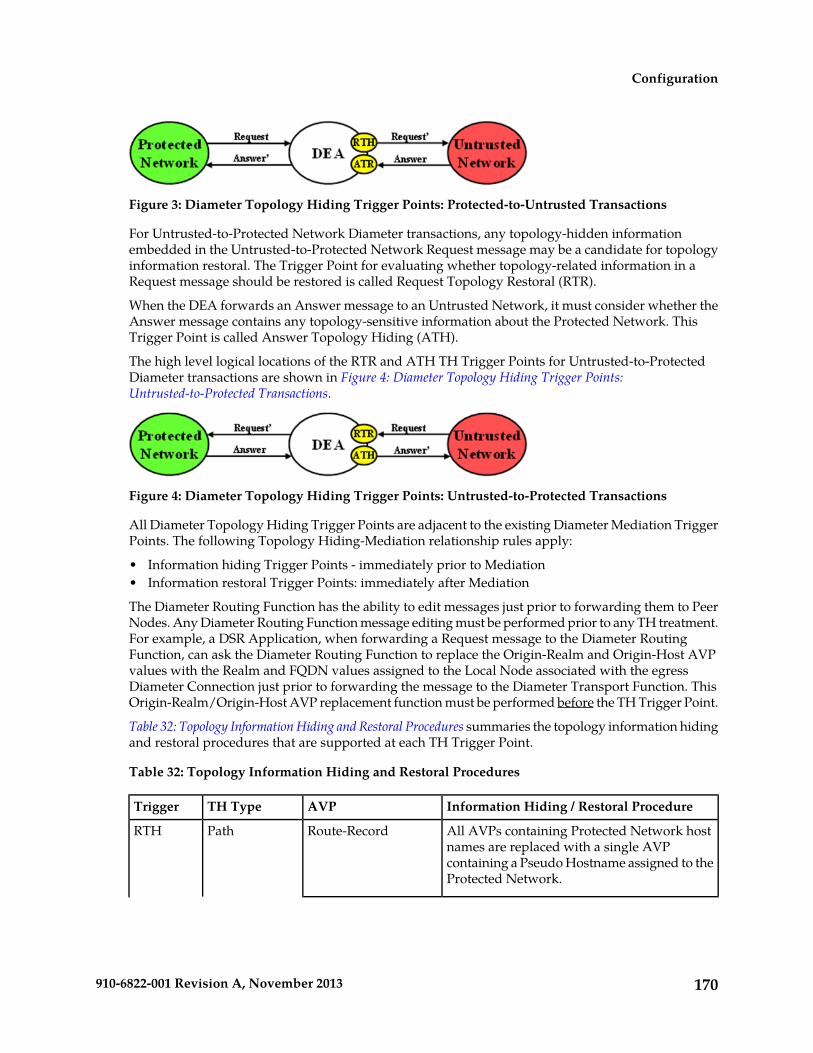
Figure 3: Diameter Topology Hiding Trigger Points: Protected-to-Untrusted Transactions
For Untrusted-to-Protected Network Diameter transactions, any topology-hidden informationembedded in the Untrusted-to-Protected Network Request message may be a candidate for topologyinformation restoral. The Trigger Point for evaluating whether topology-related information in aRequest message should be restored is called Request Topology Restoral (RTR).
When the DEA forwards an Answer message to an Untrusted Network, it must consider whether theAnswer message contains any topology-sensitive information about the Protected Network. ThisTrigger Point is called Answer Topology Hiding (ATH).
The high level logical locations of the RTR and ATH TH Trigger Points for Untrusted-to-ProtectedDiameter transactions are shown in Figure 4: Diameter Topology Hiding Trigger Points:Untrusted-to-Protected Transactions.
Figure 4: Diameter Topology Hiding Trigger Points: Untrusted-to-Protected Transactions
All Diameter Topology Hiding Trigger Points are adjacent to the existing Diameter Mediation TriggerPoints. The following Topology Hiding-Mediation relationship rules apply:
• Information hiding Trigger Points - immediately prior to Mediation• Information restoral Trigger Points: immediately after Mediation
The Diameter Routing Function has the ability to edit messages just prior to forwarding them to PeerNodes. Any Diameter Routing Function message editing must be performed prior to any TH treatment.For example, a DSR Application, when forwarding a Request message to the Diameter RoutingFunction, can ask the Diameter Routing Function to replace the Origin-Realm and Origin-Host AVPvalues with the Realm and FQDN values assigned to the Local Node associated with the egressDiameter Connection just prior to forwarding the message to the Diameter Transport Function. ThisOrigin-Realm/Origin-Host AVP replacement function must be performed before the TH Trigger Point.
Table 32: Topology Information Hiding and Restoral Procedures summaries the topology information hidingand restoral procedures that are supported at each TH Trigger Point.
Table 32: Topology Information Hiding and Restoral Procedures
Information Hiding / Restoral ProcedureAVPTH TypeTrigger
All AVPs containing Protected Network hostnames are replaced with a single AVP
Route-RecordPathRTH
containing a Pseudo Hostname assigned to theProtected Network.
170910-6822-001 Revision A, November 2013
Configuration
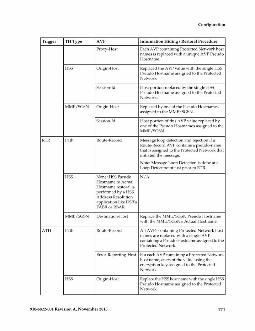
Information Hiding / Restoral ProcedureAVPTH TypeTrigger
Each AVP containing Protected Network hostnames is replaced with a unique AVP PseudoHostname.
Proxy-Host
Replaced the AVP value with the single HSSPseudo Hostname assigned to the ProtectedNetwork
Origin-HostHSS
Host portion replaced by the single HSSPseudo Hostname assigned to the ProtectedNetwork.
Session-Id
Replaced by one of the Pseudo Hostnamesassigned to the MME/SGSN.
Origin-HostMME/SGSN
Host portion of this AVP value replaced byone of the Pseudo Hostnames assigned to theMME/SGSN
Session-Id
Message loop detection and rejection if aRoute-Record AVP contains a pseudo-name
Route-RecordPathRTR
that is assigned to the Protected Network thatinitiated the message.
Note: Message Loop Detection is done at aLoop Detect point just prior to RTR.
N/ANone; HSS PseudoHostname to Actual
HSS
Hostname restoral isperformed by a HSSAddress Resolutionapplication like DSR'sFABR or RBAR.
Replace the MME/SGSN Pseudo Hostnamewith the MME/SGSN's Actual Hostname.
Destination-HostMME/SGSN
All AVPs containing Protected Network hostnames are replaced with a single AVP
Route-RecordPathATH
containing a Pseudo Hostname assigned to theProtected Network.
For each AVP containing a Protected Networkhost name, encrypt the value using the
Error-Reporting-Host
encryption key assigned to the ProtectedNetwork.
Replace the HSS host name with the single HSSPseudo Hostname assigned to the ProtectedNetwork.
Origin-HostHSS
171910-6822-001 Revision A, November 2013
Configuration
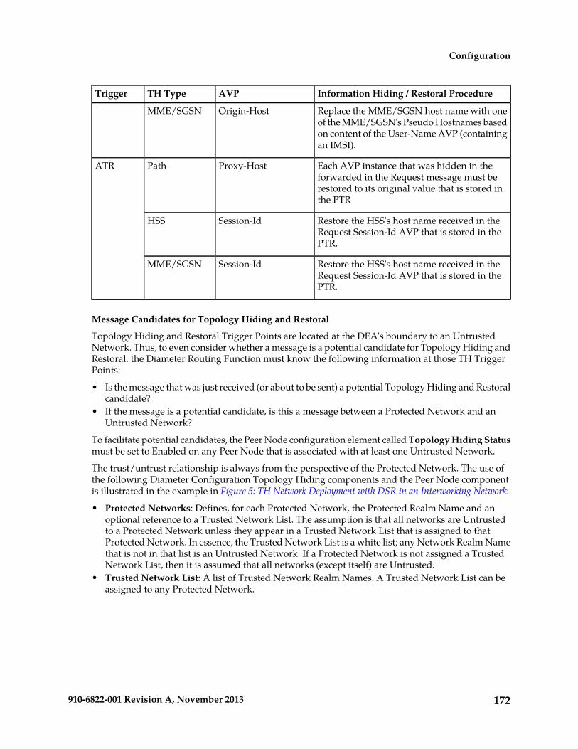
Information Hiding / Restoral ProcedureAVPTH TypeTrigger
Replace the MME/SGSN host name with oneof the MME/SGSN's Pseudo Hostnames based
Origin-HostMME/SGSN
on content of the User-Name AVP (containingan IMSI).
Each AVP instance that was hidden in theforwarded in the Request message must be
Proxy-HostPathATR
restored to its original value that is stored inthe PTR
Restore the HSS's host name received in theRequest Session-Id AVP that is stored in thePTR.
Session-IdHSS
Restore the HSS's host name received in theRequest Session-Id AVP that is stored in thePTR.
Session-IdMME/SGSN
Message Candidates for Topology Hiding and Restoral
Topology Hiding and Restoral Trigger Points are located at the DEA's boundary to an UntrustedNetwork. Thus, to even consider whether a message is a potential candidate for Topology Hiding andRestoral, the Diameter Routing Function must know the following information at those TH TriggerPoints:
• Is the message that was just received (or about to be sent) a potential Topology Hiding and Restoralcandidate?
• If the message is a potential candidate, is this a message between a Protected Network and anUntrusted Network?
To facilitate potential candidates, the Peer Node configuration element called Topology Hiding Statusmust be set to Enabled on any Peer Node that is associated with at least one Untrusted Network.
The trust/untrust relationship is always from the perspective of the Protected Network. The use ofthe following Diameter Configuration Topology Hiding components and the Peer Node componentis illustrated in the example in Figure 5: TH Network Deployment with DSR in an Interworking Network:
• Protected Networks: Defines, for each Protected Network, the Protected Realm Name and anoptional reference to a Trusted Network List. The assumption is that all networks are Untrustedto a Protected Network unless they appear in a Trusted Network List that is assigned to thatProtected Network. In essence, the Trusted Network List is a white list; any Network Realm Namethat is not in that list is an Untrusted Network. If a Protected Network is not assigned a TrustedNetwork List, then it is assumed that all networks (except itself) are Untrusted.
• Trusted Network List: A list of Trusted Network Realm Names. A Trusted Network List can beassigned to any Protected Network.
172910-6822-001 Revision A, November 2013
Configuration

Figure 5: TH Network Deployment with DSR in an Interworking Network
For the sake of discussion, assume that all of the networks are Protected Networks and the ProtectedNetworks and Trusted Network Lists shown in Table 33: Example Protected Networks Configuration andTable 34: Example Trusted Network Lists Configuration are configured:
Table 33: Example Protected Networks Configuration
Trusted Network List NameProtected Network Realm NameProtected Network Name
Trusted Networks-1n1.comN1
Trusted Networks-2n2.comN2
Trusted Networks-3n3.comN3
Trusted Networks-4n4.comN4
Table 34: Example Trusted Network Lists Configuration
Network Realm ListProtected Network Name
n3.comTrusted Networks-1
n3.comTrusted Networks-2
n4.com
n2.comTrusted Networks-3
n1.comTrusted Networks-4
n2.com
n3.com
Based on the example Protected Networks and Trusted Network Lists, the "trust" relationship matrixamong the four networks in this example configuration is shown in Table 35: Network Trust RelationshipMatrix.
173910-6822-001 Revision A, November 2013
Configuration

Table 35: Network Trust Relationship Matrix
Relationship with Peer NetworkProtectedNetwork N4N3N2N1
Not TrustedTrustedNot TrustedTrustedN1
TrustedTrustedTrustedNot TrustedN2
Not TrustedTrustedTrustedNot TrustedN3
TrustedTrustedTrustedTrustedN4
YesNoYesYesIs this networkUntrusted by atleast one othernetwork?
Based on the Network Trust Relationship Matrix, the Peer Node element settings for the networkshown in Table 36: Example Topology Hiding Status Settings would be used:
Table 36: Example Topology Hiding Status Settings
Topology Hiding Status Element SettingPeer Node
EnabledPeer Node-1
EnabledPeer Node-2
DisabledPeer Node-3
EnabledPeer Node-4
With the information in Table 36: Example Topology Hiding Status Settings, the TH type-independentcriteria for determining whether a message is a potential candidate for Topology Hiding/Restoral aredefined in Table 37: General Criteria for Determining Whether a Message is a TH Candidate.
Table 37: General Criteria for Determining Whether a Message is a TH Candidate
General Topology Hiding/RestoralCandidate Criteria
Message PathMessageTH Trigger
Egress Peer Node Topology Hiding Statusis Enabled, AND
Protected-to-UntrustedRequestRTH
Origin-Realm is a Protected Network X,AND
Destination-Realm is an UntrustedNetwork to Protected Network X
Ingress Peer Node Topology Hiding Statusis Enabled, AND
Untrusted-to-ProtectedRequestRTR
174910-6822-001 Revision A, November 2013
Configuration

General Topology Hiding/RestoralCandidate Criteria
Message PathMessageTH Trigger
Destination-Realm is a Protected NetworkX, AND
Origin-Realm is an Untrusted Network toProtected Network X
Egress Peer Node Topology Hiding Statusis Enabled, AND
Protected-to-UntrustedAnswerATH
Origin-Realm is a Protected Network X,AND
Realm of the Diameter Node that originatedthe transaction is an Untrusted Network toProtected Network X
TH Trigger point ATH occurs after theDiameter Routing Function deallocates thePTR for the transaction. Therefore, theOrigin-Realm value that was received inthe Request message must be stored in theApplication-Data stack event just prior todeallocating the PTR in order for theDiameter Routing Function to make anevaluation at ATH of whether the Answerresponse is being sent to an UntrustedNetwork.
PTR contains one or more indications thattopology information restoral is required
Untrusted-to-ProtectedAnswerATR
For Untrusted-to-Protected Answermessages, any information that was hiddenin the egress Request is a candidate forrestoral regardless of which "Network"sends the Answer message response.Topology information restoral at ATR isalways performed regardless of the egressPeer Node's Topology Hiding Status ifTopology Hiding was performed on theegress Request message for this Diametertransaction.
If the TH Trigger Point criteria defined in Table 37: General Criteria for Determining Whether a Messageis a TH Candidate are met, then the Diameter Routing Function must determine which TH types areenabled for the associated Protected Network. Each TH type might have additional criteria that mustbe met in order to determine whether topology-related information hiding or restoral is required.
The Protected Networks configuration component defines which TH types are enabled for the ProtectedNetwork. If a Configuration Set for the TH type is assigned to the Protected Network, then that THtype is enabled for that Protected Network and the rules for that TH type are applied. The Path,S6a/S6d HSS, and MME/SGSN TH types are supported. An example Protected Network component
175910-6822-001 Revision A, November 2013
Configuration
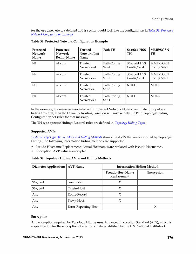
for the use case network defined in this section could look like the configuration in Table 38: ProtectedNetwork Configuration Example:
Table 38: Protected Network Configuration Example
MME/SGSNTH
S6a/S6d HSSTH
Path THTrustedNetwork ListName
ProtectedNetworkRealm Name
ProtectedNetworkName
MME/SGSNConfig Set-1
S6a/S6d HSSConfig Set-1
Path ConfigSet-1
TrustedNetworks-1
n1.comN1
MME/SGSNConfig Set-1
S6a/S6d HSSConfig Set-1
Path ConfigSet-2
TrustedNetworks-2
n2.comN2
NULLNULLPath ConfigSet-3
TrustedNetworks-3
n3.comN3
NULLNULLPath ConfigSet-4
TrustedNetworks-4
n4.comN4
In the example, if a message associated with Protected Network N3 is a candidate for topologyhiding/restoral, then the Diameter Routing Function will invoke only the Path Topology HidingConfiguration Set rules for that message.
The TH type-specific Hiding/Restoral rules are defined in Topology Hiding Types.
Supported AVPs
Table 39: Topology Hiding AVPs and Hiding Methods shows the AVPs that are supported by TopologyHiding. The following information hiding methods are supported:
• Pseudo Hostname Replacement: Actual Hostnames are replaced with Pseudo Hostnames.• Encryption: AVP value is encrypted
Table 39: Topology Hiding AVPs and Hiding Methods
Information Hiding MethodAVP NameDiameter Applications
EncryptionPseudo-Host NameReplacement
XSession-IdS6a, S6d
XOrigin-HostS6a, S6d
XRoute-RecordAny
XProxy-HostAny
XError-Reporting-HostAny
Encryption
Any encryption required by Topology Hiding uses Advanced Encryption Standard (AES), which isa specification for the encryption of electronic data established by the U.S. National Institute of
176910-6822-001 Revision A, November 2013
Configuration

Standards and Technology (NIST) in 2001. AES has been adopted by the U.S. government and is nowused worldwide. It supersedes the Data Encryption Standard (DES) that was published in 1977.
AES is an iterative, symmetric-key block cipher that can use keys of 128, 192, and 256 bits (with 256being the hardest to crack), and encrypts and decrypts data in blocks of 128 bits (16 bytes). Unlikepublic-key ciphers that use a pair of keys, symmetric-key ciphers use the same key to encrypt anddecrypt data. Encrypted data returned by block ciphers have the same number of bits that the inputdata had. Iterative ciphers use a loop structure that repeatedly performs permutations and substitutionsof the input data. All three key lengths are sufficient to protect classified information up to the SECRETlevel.
AES must be used in conjunction with a FIPS (Federal Information Processing Standard) approved orNIST recommended mode of operation. The mode specifies how data will be encrypted(cryptographically protected) and decrypted (returned to original form). Diameter Topology Hidingsupports AES-Cipher BlockChaining (CBC) mode and a 128-bit key size.
Note: If assistance is needed in troubleshooting encrypted Error-Reporting-Host AVPs, contact yourCustomer Care Center. You will need the Encryption Key that is configured in the Diameter >Configuration > Topology > Path Topology Configuration Set GUI page.
Assumptions
Diameter Topology Hiding has the following assumptions:
• In order to detect message looping for Request messages containing a Route-Record PseudoHostname, all Diameter Edge Agents in the service provider's network must have the same TopologyHiding configuration.
• A message loop for Request messages containing a Route-Record Pseudo Hostname may not bedetected for messages returned to any Diameter Edge Agent from any network that is trusted bythe Protected Network that initiated the Diameter transaction.
Topology Hiding TypesTopology Hiding can be a Diameter application-specific or Diameter application-independentprocedure.
• Topology Hiding is Diameter application-specific if the rules apply only to a Diameterapplication-specific message set (such as S6a).
• Topology Hiding is Diameter application-independent if the rules apply to any Diameter message(any Command Code).
The information to be hidden can be controlled based upon the following Topology Hiding types:
• S6a/S6d Topology Hiding
S6a/S6d Topology Hiding is applied only to the S6a/S6d Command Codes defined in 3GPP TS29.272, "Mobility Management Entity (MME) and Serving GPRS Support Node (SGSN) relatedinterfaces based on Diameter protocol", and requires knowing which S6a/S6d messages areHSS-initiated versus MME/SGSN-initiated.
• S6a/S6d HSS Topology Hiding
S6a/S6d HSS Topology Hiding is concerned with hiding the identity(s) of a Protected Network'sHSS when it exchanges messages with Untrusted Networks. An HSS's Hostname is embeddedin the Origin-Host and Session-Id AVPs sent in Request messages and in the Origin-Host AVPsent in Answer messages.
177910-6822-001 Revision A, November 2013
Configuration
S6a/S6d HSS Topology Hiding determines which entity (HSS or MME/SGSN) initiated amessage, based on the Command Code in the message.
S6a/S6d HSS Topology Hiding can be enabled for each Protected Network, by assigning anS6a/S6d HSS Topology Hiding Configuration Set to the configured Protected Network.
• MME/SGSN Topology Hiding
MME/SGSN Topology Hiding is concerned with hiding the identity of a Protected HomeNetwork's MME/SGSNs, as well as the number of MME/SGSNs in the network, when itexchanges messages with Untrusted Networks. A MME/SGSN's identity is embedded in theOrigin-Host and Session-Id AVPs sent in Request messages and in the Origin-Host AVP sentin Answer messages.
MME/SGSN Topology Hiding determines which entity (HSS or MME/SGSN) initiated anS6a/S6d message, based on the Command Code in the message.
MME/SGSN Topology Hiding can be enabled for each Protected Network, by assigning anMME/SGSN Topology Hiding Configuration Set to the configured Protected Network.
• Path Topology Hiding
Path Topology Hiding is Diameter application-independent, and can be applied to any DiameterCommand Code.
Path Topology Hiding is concerned with hiding a Protected Network's Hostnames and the numberof hosts in the following AVPs:
• Route-Record AVP: Sent in Request messages. More than one Route-Record AVP can exist ina Request message.
• Proxy-Host AVP: An AVP embedded in the grouped Proxy-Info AVP that is sent in Requestand Answer messages. More than one Proxy-Host AVP can exist in a message.
• Error-Reporting-Host AVP: Sent in Answer messages. More than one Error-Reporting-HostAVP can exist in an Answer message.
Path Topology Hiding can be enabled for each Protected Network, by assigning a Path TopologyHiding Configuration Set to the configured Protected Network.
S6a/S6d HSS Topology HidingS6a/S6d HSS Topology Hiding is concerned with hiding the identities of a Protected Network's HSSwhen it exchanges messages with Untrusted Networks. An HSS's host name is embedded in theOrigin-Host and Session-Id AVPs sent in Request messages and the Origin-Host AVP sent in Answermessages. This capability is associated with the Diameter S6a/S6d application message set defined in3GPP TS 29.272, "Mobility Management Entity (MME) and Serving GPRS Support Node (SGSN) relatedinterfaces based on Diameter protocol".
S6a/S6d HSS Topology Hiding determines which entity (HSS or MME/SGSN) initiated a messagebased on the Command Code in the message.
HSS identities are hidden by replacing the Hostname portion of the Origin-Host and Session-Id AVPs(Session-Id format: <host name><implementation portion>) with an operator-defined HSS PseudoHostname that is assigned to the Protected Network in the S6a/S6d HSS Topology Hiding ConfigurationSet.
178910-6822-001 Revision A, November 2013
Configuration

Protected-HSS to Untrusted-MME/SGSN Transactions
For Protected-HSS to Untrusted-MME/SGSN Diameter transactions, S6a/S6d HSS Topology Hidingis concerned with the following topology information hiding and restoral issues:
• The AVPs containing an HSS's Actual Hostname in Request messages must be hidden with thesingle HSS Pseudo Hostname assigned to the Protected Network at TH Trigger Point RTH.
• The MME/SGSN will send an Answer response to the transaction with the Session-Id received inthe Request (which also contains an HSS Pseudo Hostname). Because the Session-Id value returnedin the Answer must match the value sent in the Request, the HSS Pseudo Hostnames in the Answermessage Session-Id AVP must be restored with the HSS Hostname or Hostnames sent in the Requestmessage.
The Session-Id AVP values are restored at TH Trigger Point ATR, from the Hostname portion ofthe Session-Id AVP value that is saved in the Pending Transaction Record (PTR).
The Hostname restoral procedure is not required for Answers initiated by DSR internal nodes(Diameter Routing Function and DSR Applications) as these Answer responses are based uponthe original Request message content and thus do not contain Pseudo Hostnames.
An example of a Protected-HSS to Untrusted-MME/SGSN Diameter transaction is shown in Figure 6:S6a/S6d HSS TH Protected-HSS to Untrusted-MME/SGSN Diameter Transaction.
Figure 6: S6a/S6d HSS TH Protected-HSS to Untrusted-MME/SGSN Diameter Transaction
For Protected-HSS to Untrusted-MME/SGSN transactions, S6a/S6d HSS topology information hidingis required only on Request messages that meet the following criteria:
• Message was a candidate for Topology Hiding as defined by TH Trigger Point RTH in Table 37:General Criteria for Determining Whether a Message is a TH Candidate
• S6a/S6d HSS Topology Hiding is enabled for the Protected Network (an S6a/S6d HSS TopologyHiding Configuration Set is assigned to the Protected Network)
• The Request message is a member of the S6a/S6d message set and was initiated by an HSS asdetermined from the Command Code in the message
For Protected-HSS to Untrusted-MME/SGSN transactions, S6a/S6d HSS topology information hidingis performed only on Answer messages that meet the following criterion:
• At TH Trigger Point ATR, the "S6a/S6d HSS TH ATR" flag in the PTR associated with the Answermessage is set to "Enabled".
When the above criterion is met, Session-Id AVP restoral will be performed using the HSS's ActualHostname stored in the PTR.
179910-6822-001 Revision A, November 2013
Configuration

Untrusted-MME/SGSN to Protected-HSS Transactions
For Untrusted-MME/SGSN to Protected-HSS Diameter transactions, S6a/S6d HSS TH is concernedwith the following topology information hiding and restoral issue:
• The HSS-initiated Answer response will contain an HSS Actual Hostname in the Origin-Host AVP.The Actual Hostname must be hidden with the HSS Pseudo Hostname or Hostnames assigned tothe Protected Network at TH Trigger Point ATH.
Restoral of a Protected-HSS's Actual Hostname in the Untrusted-MME/SGSN to Protected-HSS Requestmessage is not performed by Topology Hiding. Instead, this replacement function is required of anHSS Address Resolution application such as the FABR and RBAR DSR Applications.
For Untrusted-MME/SGSN to Protected-HSS transactions, S6a/S6d HSS topology information hidingis required only on Answer messages that meet the following criteria:
• Message was a candidate for Topology Hiding as defined by topology Trigger Point ATH in Table37: General Criteria for Determining Whether a Message is a TH Candidate
• S6a/S6d HSS Topology Hiding is enabled for the Protected Network (an S6a/S6d HSS TopologyHiding Configuration Set is assigned to the Protected Network)
• The Answer message is a member of the S6a/S6d message set and was initiated by an HSS asdetermined from the Command Code in the message
An example of an Untrusted-MME/SGSN to Protected-HSS Diameter transaction is shown in Figure7: S6a/S6d HSS TH Untrusted-MME/SGSN to Protected-HSS Transaction.
Figure 7: S6a/S6d HSS TH Untrusted-MME/SGSN to Protected-HSS Transaction
MME/SGSN Topology HidingMME/SGSN Topology Hiding is concerned with hiding the identity of a Protected Home Network'sMME/SGSNs and the number of MME/SGSNs in the network, when it exchanges messages withUntrusted Networks. A MME/SGSN's identity is embedded in the Origin-Host and Session-Id AVPssent in Request messages and in the Origin-Host AVP sent in Answer messages. MME/SGSN TopologyHiding is associated with the Diameter S6a/S6d application message set defined in 3GPP TS 29.272,"Mobility Management Entity (MME) and Serving GPRS Support Node (SGSN) related interfacesbased on Diameter protocol".
MME/SGSN Topology Hiding determines which entity (HSS or MME/SGSN) initiated an S6a/S6dmessage based on the Command Code in the message.
MME/SGSN identities are hidden by replacing the Actual Hostname portion of the Origin-Host andSession-Id AVPs (Session-Id format: <host name><implementation portion>) with an MME/SGSNPseudo Hostname. The Origin-Host and Session-Id AVPs can have different MME/SGSN Hostnames.A unique Pseudo Hostname must be created for each MME/SGSN in a Protected Network. When theMME/SGSN initiates a transaction to the HSS, the HSS saves the MME/SGSN's identity for use in
180910-6822-001 Revision A, November 2013
Configuration

subsequent HSS-to-MME/SGSN transactions. This MME/SGSN Pseudo Hostname must not only beunique, but the DEA must be able to convert the MME/SGSN's Pseudo Hostname to an ActualMME/SGSN Hostname for these subsequent HSS-to-MME/SGSN transactions.
In order to hide the number of MME/SGSNs in a network, each MME/SGSN will be assigned eithera random or fixed number of Pseudo Hostnames. A maximum number is defined by the Count in thePseudo Hostname Generation attribute of the MME/SGSN Topology Hiding Configuration Set. TheRandomize Count creates a random number of Pseudo Hostnames, between 1 and the Count value,that are associated with an Actual Hostname. This procedure of creating randomized MME/SGSNPseudo Hostnames and assigning them to an Actual Pseudo Hostname is performed by the GUI, thenused by the Diameter Routing Function. The created MME/SGSN TH Hostnames allow the DiameterRouting Function to map a Protected-MME/SGSN Actual Hostname to a set of MME/SGSN PseudoHostnames, and to map a MME/SGSN Pseudo Hostname received from an Untrusted-HSS to aProtected-MME/SGSN Actual Hostname.
Table 40: Example of Configuration of MME/SGSN TH Hostnames for a Protected Network shows an exampleof MME/SGSN TH Host Names configuration for a Protected Network with a maximum of 3 randomlycreated Pseudo Hostnames.
Table 40: Example of Configuration of MME/SGSN TH Hostnames for a Protected Network
MME/SGSN PseudoHostnames
MME/SGSN Actual HostnameMME/SGSN TH Configuration SetName
mme042.example.commme1.westregion.example.comProtected Network-1 MME/SGSNConfig mme821.example.com
mme123.example.commme1.westregion.example.comProtected Network-1 MME/SGSNConfig
mme533.example.commme2.westregion.example.comProtected Network-1 MME/SGSNConfig mme773.example.com
mme092.example.com
mme922.example.commme1.eastregion.example.comProtected Network-1 MME/SGSNConfig mme729.example.com
mme411.example.commme2.eastregion.example.comProtected Network-1 MME/SGSNConfig mme002.example.com
mme655.example.com
mme218.example.commme2.eastregion.example.comProtected Network-1 MME/SGSNConfig
mme331.example.commme2.eastregion.example.comProtected Network-1 MME/SGSNConfig mme249.example.com
mme447.example.com
mme776.example.commme1.texasregion.example.comProtected Network-1 MME/SGSNConfig
181910-6822-001 Revision A, November 2013
Configuration

MME/SGSN PseudoHostnames
MME/SGSN Actual HostnameMME/SGSN TH Configuration SetName
mme077.example.com
mme295.example.commme1.texasregion.example.comProtected Network-1 MME/SGSNConfig mme622.example.com
mme861.example.com
mme333.example.commme1.texasregion.example.comProtected Network-1 MME/SGSNConfig
Protected-MME/SGSN to Untrusted-HSS Transactions
For Protected-MME/SGSN to Untrusted-HSS Diameter transactions, MME/SGSN Topology Hidingis concerned with the following topology information hiding and restoral issues:
• The AVPs containing an MME/SGSN's Actual Hostname in Request messages must be hiddenwith one of the Pseudo Hostnames assigned to the MME/SGSN at TH Trigger Point RTH.
• The HSS saves the subscriber's location using the Origin-Host AVP contents containing a PseudoHostname. In subsequent HSS-to-MME/SGSN transactions, the MME/SGSN will be addressedby one of its Pseudo Hostnames, requiring a Pseudo-to-Actual Hostname restoral.
• All MME/SGSN-to-HSS transactions associated with a particular subscriber must use the sameMME/SGSN Pseudo Hostname. Otherwise, the HSS will think that the subscriber has moved toanother MME/SGSN and unnecessarily change the subscriber's location. For S6a/S6d transactions,the subscriber associated with the transaction is identified by an IMSI, which for the S6a/S6dmessage set is embedded in the User-Name AVP, a mandatory AVP in all MME/SGSN-to-HSSRequest messages.
Note: Although the Origin-Host and Session-Id AVPs both have MME/SGSN Actual Hostnames,the names could be different. Because the HSS associates the MME/SGSN's location based on theOrigin-Host AVP content, it is the MME/SGSN Actual Hostname in the Origin-Host AVP thatmust be used for selecting a MME/SGSN Pseudo Hostname. This MME/SGSN Pseudo Hostnamecan be used to replace both of the Hostname fields in the forwarded Request message.
• The HSS sends an Answer response to the transaction with the Session-Id received in the Requestand containing an MME/SGSN Pseudo Hostname. Because the Session-Id value returned in theAnswer must match the value in the Request, the MME/SGSN Pseudo Hostname in the Session-IdAVP must be replaced with its corresponding value received in the Request message. The valueis restored at TH Trigger Point ATR, with the Hostname portion of the Session-Id AVP value thatis stored in the PTR.
This Hostname restoral procedure is not required for Answers initiated by DSR internal nodes (theDiameter Routing Function and DSR Applications) as these Answer responses are based upon theoriginal Request message content.
An example of a Protected-MME/SGSN to Untrusted-HSS Diameter transaction is shown in Figure 8:MME/SGSN TH Protected-MME/SGSN to Untrusted HSS Transaction.
182910-6822-001 Revision A, November 2013
Configuration
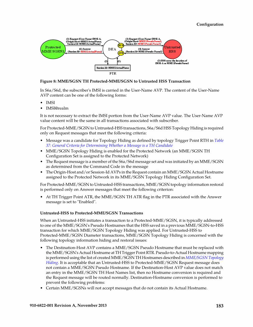
Figure 8: MME/SGSN TH Protected-MME/SGSN to Untrusted HSS Transaction
In S6a/S6d, the subscriber's IMSI is carried in the User-Name AVP. The content of the User-NameAVP content can be one of the following forms:
• IMSI• IMSI@realm
It is not necessary to extract the IMSI portion from the User-Name AVP value. The User-Name AVPvalue content will be the same in all transactions associated with subscriber.
For Protected-MME/SGSN to Untrusted-HSS transactions, S6a/S6d HSS Topology Hiding is requiredonly on Request messages that meet the following criteria:
• Message was a candidate for Topology Hiding as defined by topology Trigger Point RTH in Table37: General Criteria for Determining Whether a Message is a TH Candidate
• MME/SGSN Topology Hiding is enabled for the Protected Network (an MME/SGSN THConfiguration Set is assigned to the Protected Network)
• The Request message is a member of the S6a/S6d message set and was initiated by an MME/SGSNas determined from the Command Code in the message
• The Origin-Host and/or Session-Id AVPs in the Request contain an MME/SGSN Actual Hostnameassigned to the Protected Network in its MME/SGSN Topology Hiding Configuration Set.
For Protected-MME/SGSN to Untrusted-HSS transactions, MME/SGSN topology information restoralis performed only on Answer messages that meet the following criterion:
• At TH Trigger Point ATR, the MME/SGSN TH ATR flag in the PTR associated with the Answermessage is set to "Enabled".
Untrusted-HSS to Protected-MME/SGSN Transactions
When an Untrusted-HSS initiates a transaction to a Protected-MME/SGSN, it is typically addressedto one of the MME/SGSN's Pseudo Hostnames that the HSS saved in a previous MME/SGSN-to-HSStransaction for which MME/SGSN Topology Hiding was applied. For Untrusted-HSS toProtected-MME/SGSN Diameter transactions, MME/SGSN Topology Hiding is concerned with thefollowing topology information hiding and restoral issues:
• The Destination-Host AVP contains a MME/SGSN Pseudo Hostname that must be replaced withthe MME/SGSN's Actual Hostname at TH Trigger Point RTR. Pseudo-to-Actual Hostname mappingis performed using the list of created MME/SGSN TH Hostnames described in MME/SGSN TopologyHiding. It is acceptable that an Untrusted-HSS to Protected-MME/SGSN Request message doesnot contain a MME/SGSN Pseudo Hostname. If the Destination-Host AVP value does not matchan entry in the MME/SGSN TH Host Names list, then no Hostname conversion is required andthe Request message will be routed normally. Destination-Hostname conversion is performed toprevent the following problems:
• Certain MME/SGSNs will not accept messages that do not contain its Actual Hostname.
183910-6822-001 Revision A, November 2013
Configuration

• DSR routing problems associated with Pseudo Hostnames. For example, Diameter "Implicit Routing"works only with Actual Hostnames (such as the FQDN assigned to the Peer Node and used forthe Capabilities Exchange procedure [CER/CEA]).
• An Origin-Host AVP containing an MME/SGSN's Actual Hostname in the Answer response fromthe Protected-MME/SGSN must be hidden with one of the Pseudo Hostnames assigned to thatMME/SGSN. This is done at TH Trigger Point ATH.
An example of an Untrusted-HSS to Protected-MME/SGSN Diameter transaction is shown in Figure9: MME/SGSN TH Untrusted-HSS to Protected MME/SGSN Transaction.
Figure 9: MME/SGSN TH Untrusted-HSS to Protected MME/SGSN Transaction
For Untrusted-HSS to Protected-MME/SGSN transactions, S6a/S6d HSS Topology Hiding is invokedonly on Request messages that meet the following criteria:
• Message was a candidate for topology Hiding as defined by TH Trigger Point RTR in Table 37:General Criteria for Determining Whether a Message is a TH Candidate
• MME/SGSN Topology Hiding is enabled for the Protected Network (an MME/SGSN TopologyHiding Configuration Set is assigned to the Protected Network)
• The Request message is a member of the S6a/S6d message set and was initiated by an MME/SGSNas determined from the Command Code in the message
• The Destination-Host AVP contains a MME/SGSN Pseudo Hostname that is assigned to theProtected Network as determined from the list of created MME/SGSN TH Host Names describedin MME/SGSN Topology Hiding.
For Untrusted-HSS to Protected-MME/SGSN transactions, S6a/S6d HSS Topology Hiding is invokedonly on Answer messages at TH Trigger Point ATH that meet the following criteria:
• Message was a candidate for Topology Hiding as defined by topology Trigger Point ATH in Table37: General Criteria for Determining Whether a Message is a TH Candidate
• MME/SGSN Topology Hiding is enabled for the Protected Network (an MME/SGSN TopologyHiding Configuration Set is assigned to the Protected Network)
• The Answer message is a member of the S6a/S6d message set and was initiated by an MME/SGSNas determined from the Command Code in the message
• The Origin-Host AVP contains an MME/SGSN Actual Hostname that is assigned to the ProtectedNetwork in its MME/SGSN Topology Hiding Configuration Set.
Path Topology HidingPath Topology Hiding is concerned with hiding the identities of a Protected Network's hiding aProtected Network's Hostnames and the number of hosts in the following AVPs:
• Route-Record AVP: Sent in Request messages. More than one Route-Record AVP may exist in aRequest message.
• Proxy-Host AVP: An AVP embedded in the Grouped Proxy-Info AVP that is sent in Request andAnswer messages. More than one Proxy-Host AVP may exist in a message.
• Error-Reporting-Host AVP: Sent in Answer messages. More than one Error-Reporting-Host AVPcould exist in an Answer message.
184910-6822-001 Revision A, November 2013
Configuration

Path Topology Hiding can be enabled for each Protected Network, by assigning a Path TH ConfigurationSet to the configured Protected Network.
Route-Record AVP Hostname Hiding - Request Messages
Route-Records AVPs are appended to Request messages to assist in message loop detection. WhenDiameter node N relays a Request message received from Diameter node –1 to Diameter node N+1,Diameter node N appends a Route-Record AVP to the Request message containing the Hostname ofDiameter node –1. For Request messages that are forwarded from a Protected Network N1 to anUntrusted Network, there could be Protected Network N1 Hostnames embedded in one or more ofthe Route-Record AVPs.
Route-Record AVP Hostname hiding is performed only on Request messages that meet the followingcriteria:
• Message is a candidate for Topology Hiding as defined by topology Trigger Point RTH in Table 37:General Criteria for Determining Whether a Message is a TH Candidate
• Path Topology Hiding is enabled for the Protected Network (a Path TH Configuration Set is assignedto the configured Protected Network)
• At least one of the Route-Record AVPs contains a Protected Network Hostname.
An example of Route-Record AVP Hostname hiding for a Request message routed from a ProtectedNetwork to an Untrusted Network is shown in Figure 10: Route-Record Hiding - Request Message.
Figure 10: Route-Record Hiding - Request Message
The Path Topology Hiding Configuration Set assigned to the Protected Network has the followingelements that are used for Route-Record Topology Hiding:
• Hostname Suffixes - A list of Protected Network Hostname Suffixes that are used to specify whichHostnames to hide when messages are forwarded to Untrusted Networks. Any Route-Record AVPscontaining a Hostname not matching an entry in this Hostname Suffixes list will not be hidden.
• Route-Record Pseudo Hostname - The Pseudo Hostname to be used when replacing all of theRoute-Record AVPs that contain a Hostname that meets the Route-Record AVP hiding criteria.
Route-Record AVP Hostname hiding is performed by replacing all of the Route-Record AVPs thatmeet the Route-Record AVP hiding criteria with a single Route-Record AVP that contains a singleconfigured Pseudo Hostname. Route-Record AVP Hostname hiding occurs after the Diameter RoutingFunction appends any Route-Record AVPs to the Request message.
Route-Record AVP Hostname Hiding - Answer Messages
Diameter Relay and Proxy Agents are required to append a Route-Record AVP into any forwardedRequest message. There are no Relay Agent or Proxy Agent requirements to perform this function forAnswer messages. However, in certain Diameter specifications (such as S6a/S6d and RFC 4006), theRoute-Record AVP is specified as an optional AVP in certain Answer messages (including CCA andmost of the S6a/S6d Answer messages). Thus, it is probable that Answer messages initiated by aProtected Network node and forwarded to an Untrusted Network by a DEA can contain one or moreRoute-Record AVPs with Protected Network Hostnames. Therefore, Route-Record AVP Hostnamehiding will be applied to Answer messages using the same procedure that is used for Request messages.
185910-6822-001 Revision A, November 2013
Configuration

Route-Record AVP Hostname hiding is performed only on Answer messages that meet the followingcriteria:
• Message is a candidate for Topology Hiding as defined by topology Trigger Point ATH in Table37: General Criteria for Determining Whether a Message is a TH Candidate
• Path Topology Hiding is enabled for the Protected Network (a Path Topology Hiding ConfigurationSet is assigned to the configured Protected Network)
• At least one of the Route-Record AVPs contains a Protected Network Hostname
An example of Route-Record AVP Host Name hiding for an Answer message initiated by a ProtectedNetwork to an Untrusted Network is shown in Figure 11: Route-Record Hiding - Answer Message.
Figure 11: Route-Record Hiding - Answer Message
Route-Record AVP Hiding and Inter-Network Message Loop Detection
The technique of replacing one or more Route-Record AVPs with a single Route-Record AVP containinga Pseudo Hostname must not defeat the fundamental purpose of the Route-Record AVP - messageloop detection. Because Route-Record Topology Hiding is considered a DEA function and is appliedonly to Request messages leaving a network, inter-network ingress message loop detection is neededat the inter-network boundary. For example, a Request message can egress the network from DEA-1but loop back to the network through DEA-2 as shown in Figure 12: Multi-DEA Route-Record MessageLoop Detection. If an inter-network message loop is not detected by a DEA, the loop will not be detectedwithin the Protected Network because a DEA replaced the Route-Records for the internal nodes witha single Route-Record AVP containing a Pseudo Hostname.
Topology Hiding configuration components must be managed from the NOAM so that an identicalcopy of all Topology Hiding configured components will be distributed to all DEAs controlled by theNOAM. This allows inter-network ingress message loop detection to be supported by any DEA.
Inter-network ingress message loop detection is supported at the RTR Trigger Point. A typical messageloop path between two DEAs with Path Topology Hiding enabled is illustrated in Figure 9.
Figure 12: Multi-DEA Route-Record Message Loop Detection
It is possible but highly unlikely (as in an invalid inter-network relationship) that a Request messagethat leaves the Protected Network addressed to an Untrusted Network will loop back to the Protected
186910-6822-001 Revision A, November 2013
Configuration

Network through a Trusted Network, as shown in Figure 13: Unsupported Pseudo-Host Route-RecordLoop Detection. This type of message loop detection is NOT supported.
Figure 13: Unsupported Pseudo-Host Route-Record Loop Detection
Inter-network ingress message loop detection occurs when all of the following criteria are met:
• Message is a candidate for Topology Hiding as defined by TH Trigger Point RTR in Table 37: GeneralCriteria for Determining Whether a Message is a TH Candidate
• Path Topology Hiding is enabled for the Protected Network (a Path Topology Hiding ConfigurationSet is assigned to the configured Protected Network)
• A Route-Record AVP contains the Protected Network's Pseudo Hostname used for Route-RecordAVP Host Name hiding
Proxy-Host AVP Hiding and Restoral
The grouped Proxy-Info AVP allows stateless agents to add local state to a Diameter Request message,with the guarantee that the same state will be present in the Answer message response. The embeddedProxy-Host AVP identifies the Diameter node that appended the Proxy-Info AVP to the Requestmessage. A Protected Network Hostname in any Proxy-Host AVP must be hidden when the AVP isforwarded to an Untrusted Network. More than one Proxy-Host AVP instance can exist in a Requestmessage. Every instance that contains a Protected Network Hostname must be hidden with auniquePseudo Hostname.
The Path Topology Hiding Configuration Set assigned to the Protected Network has the followingelements that are used for Proxy-Host AVP Hiding:
• Hostname Suffixes - A list of Protected Network Hostname Suffixes that are used to specify whichHostnames to hide when messages are forwarded to Untrusted Networks. Any Proxy-Host AVPswith a Hostname not matching an entry in this Hostname Suffixes list will not be hidden.
• Proxy-Host Pseudo Hostname Suffix - In order to hide the number of Proxy Agents in the ProtectedNetwork, a random Proxy-Host pseudo-host name of the format <prefix><suffix> will be used,where the "prefix" is a random 3-digit value created each time Proxy-Host name substitution isperformed and "suffix" is a fixed-length string defined by this configured element. All of theProxy-Host pseudo-host names inserted into any Request message must be unique.
Proxy-Host AVP Hiding is performed only on Request messages that meet the following criteria:
• Message is a candidate for Topology Hiding as defined by TH Trigger Point RTH in Table 37: GeneralCriteria for Determining Whether a Message is a TH Candidate
• At least one of the Proxy-Host AVPs contains a Protected Network's Hostname
187910-6822-001 Revision A, November 2013
Configuration

• Path Topology Hiding is enabled for the Protected Network (a Path Topology Hiding ConfigurationSet is assigned to the Protected Network)
An example of Proxy-Host AVP Hiding for a Request message initiated by a Protected Network to anUntrusted Network is shown in Figure 14: Proxy-Host Hiding.
Figure 14: Proxy-Host Hiding
Because the Proxy-Info AVP is used by stateless agents to store local transaction state information intoa Request message and retrieve that information from the Answer response, it is important that theDEA restore the original Proxy-Host AVP values (received in the original Request message) when itforwards the Answer response message. Thus, any Proxy-Host AVP value that is replaced at THTrigger Point RTH must be saved in its respective Diameter Routing Function PTR.
Proxy-Host AVP Restoral is performed only on Answer messages that meet the following criterion:
• At TH Trigger Point ATR, the Restore Proxy-Host AVPs flag in the PTR associated with the Answermessage is set to Enabled.
When the criterion is met, Proxy-Host AVP Restoral will be performed. The Diameter Routing Functionwill replace every Proxy-Host AVP value that matches a Proxy-Host Pseudo Hostname (stored in thePTR) with the original Hostname (also stored in the PTR).
Error Reporting Host AVP Hiding
The Error-Reporting-Host AVP contains the identity of the Diameter node that set the Result-CodeAVP to a value other than 2001 (Success), only if the host setting the Result-Code is different from theone encoded in the Origin-Host AVP.
From a Topology Hiding perspective, the Hostname in this AVP must be hidden if it contains aProtected Network Hostname and is being sent to an Untrusted Network.
The content of this AVP will be hidden using encryption. Troubleshooters in the Protected Networkmust have the ability to decrypt the value. Topology Hiding uses Advanced Encryption Standard(AES), which is described in Encryption.
Although unlikely, more than one Error-Reporting-Host AVP could exist in an Answer message; eachError-Reporting-Host AVP containing a Protected Network's Hostname must be encrypted.
Error-Reporting-Host AVP Hiding is performed only on Answer messages that meet the followingcriteria:
• Message is a candidate for Topology Hiding as defined by topology Trigger Point ATH in Table37: General Criteria for Determining Whether a Message is a TH Candidate
• At least one of the Error-Reporting-Host AVPs contains a Protected Network's Hostname
188910-6822-001 Revision A, November 2013
Configuration

• Path Topology Hiding is enabled for the Protected Network (a Path Topology Hiding ConfigurationSet is assigned to the Protected Network)
An example of Error-Reporting-Host AVP Hiding for an Answer message received from a ProtectedNetwork that is being forwarded to an Untrusted Network is shown in Figure 15: Error-Reporting-HostAVP Hiding.
Figure 15: Error-Reporting-Host AVP Hiding
The Path Topology Hiding Configuration Set assigned to the Protected Network has the followingelements that are used for Error-Reporting-Host Topology Hiding:
• Hostname Suffixes - A list of Protected Network Hostname Suffixes that are used to specify whichhost names to hide when messages are forwarded to Untrusted Networks. Any Error-Reporting-HostAVPs with a Hostname not matching an entry in this Hostname Suffixes list will not be hidden.
• Error-Reporting-Host Encryption Key - User-configured encryption key that must be used forencrypting the Error-Reporting-Host AVP value. A user-configured encryption key allows theError-Reporting-Host AVP value to be decrypted in troubleshooting, if required.
Trusted Networks Lists configuration
A Trusted Network List is a list of Realms identifying networks where Topology Hiding will NOT beinvoked for messages to and from that network. Up to 500 Trusted Network Lists can be configured.Each Trusted Network List can contain up to 100 Trusted Network Realms.
Trusted Network Lists can be configured only on an NOAM.
On the Diameter > Configuration > Trusted Networks Lists page, you can perform the followingactions:
• Filter the list of Trusted Networks Lists, to display only the desired Trusted Networks Lists.
• Sort the list entries in ascending or descending order by Trusted Networks List Name by clickingthe column heading. By default, the list is sorted by Trusted Networks List Name in ascendingnumerical order.
• Click the Insert button.
The Diameter > Configuration > Trusted Networks Lists [Insert] page opens. You can add a newTrusted Networks List. See Adding a Trusted Network List. If the maximum number of TrustedNetworks Lists (500) already exists in the system, the Diameter > Configuration > Trusted NetworksLists [Insert] page will not open, and an error message is displayed.
• Select a Trusted Networks List Name in the list, and click the Edit button.
The Diameter > Configuration > Trusted Networks Lists [Edit] page opens. You can edit theselected Trusted Networks List. See Editing a Trusted Network List.
• Select a Trusted Networks List Name in the list, and click the Delete button to remove the selectedTrusted Networks List. See Deleting a Trusted Network List.
189910-6822-001 Revision A, November 2013
Configuration

Trusted Network Lists elementsTable 41: Trusted Network Lists elements describes the fields on the Diameter > Configuration > TrustedNetwork Lists View, Insert, and Edit pages. Data Input Notes apply only to the Insert and Edit pages;the View page is read-only.
Table 41: Trusted Network Lists elements
Data Input NotesDescriptionField (* indicates arequired field)
Format: case-sensitive;alphanumeric and underscore (_);
A name that uniquely identifies theTrusted Network List.
* Trusted Network ListName
cannot start with a digit and mustcontain at least one alpha
Range: 1 - 32 characters
Format: Test box; case- insensitivestring consisting of a list of labels
Trusted Network Realms for this TrustedNetwork List. For Trusted Network
* Trusted NetworkRealms
separated by dots, where a labelRealms the Topology Hiding Feature willnot be applied. may contain letters, digits, dashes
('-') and underscore ('_'). A labelClick the Add button to enter anotherRealm. must start with a letter, digit or
underscore and must end with aletter or digit. Underscores can beClick the X next to a Realm to delete the
entry. used only as the first character. Alabel can be at most 63 characterslong and a Realm can be at most255 characters long.
Range: 1-100 entries
Viewing Topology Hiding Trusted Network ListsUse this task to view configured Topology Hiding Trusted Network Lists.
On the NOAM, select Diameter > Configuration > Topology Hiding > Trusted Network Lists.The Diameter > Configuration > Topology Hiding > Trusted Network Lists page appears.
Adding a Trusted Network ListUse this task on the NOAM to create a new Trusted Network List. The fields are described in TrustedNetwork Lists elements.
1. Select Diameter > Configuration > Topology Hiding > Trusted Network Lists.The Diameter > Configuration > Topology Hiding > Trusted Network Lists page appears.
2. Click Insert.The Diameter > Configuration > Topology Hiding > Trusted Network Lists [Insert] page appears.
3. Enter a unique name for the Trusted Network List in the Trusted Network List Name field.4. Enter one or more, up to 100, Trusted Network Realms.
190910-6822-001 Revision A, November 2013
Configuration

5. Click:
• OK to save the data and return to the Diameter > Configuration > Topology Hiding > TrustedNetwork Lists page .
• Apply to save the data and remain on this page.• Cancel to return to the Diameter > Configuration > Topology Hiding > Trusted Network
Lists page without saving any changes.
If OK or Apply is clicked and any of the following conditions exist, an error message appears:
• Any required field is empty; no value was entered or selected• The entry in any field in not valid (wrong data type or out of the valid range)• The Trusted Network List Name is not unique; it already exists in the system• The maximum number of Trusted Network Lists (100) would be exceeded in the system
Editing a Trusted Network ListUse this task to make changes to existing Trusted Network Lists.
The Trusted Network List Name cannot be changed.
1. Select Diameter > Configuration > Topology Hiding > Trusted Network Lists.The Diameter > Configuration > Topology Hiding > Trusted Network Lists page appears.
2. Select the Trusted Network List you want to edit.3. Click Edit.
The Diameter > Configuration > Topology Hiding > Trusted Network Lists [Edit] page appears.
The page is initially populated with the current configured values for the selected Trusted NetworkList.
4. Update the relevant fields.For more information about each field see Trusted Network Lists elements.
5. Click:
• OK to save the data and return to the Diameter > Configuration > Topology Hiding > TrustedNetwork Lists page .
• Apply to save the data and remain on this page.• Cancel to return to the Diameter > Configuration > Topology Hiding > Trusted Network
Lists page without saving any changes.
If OK or Apply is clicked and any of the following conditions exist, an error message appears:
• Any required field is empty; no value was entered or selected• The entry in any field in not valid (wrong data type or out of the valid range)
Deleting a Trusted Network ListUse this task on the NOAM to delete a Trusted Network List.
Note: A Pending Answer Timer cannot be deleted if the Pending Answer Timer is referenced by anyof the following components:
191910-6822-001 Revision A, November 2013
Configuration
• Peer Node• Application Id• Routing Option Set
The Default Pending Answer Timer cannot be deleted.
1. Select Diameter > Configuration > > Topology Hiding > Trusted Network Lists.The Diameter > Configuration > Topology Hiding > Trusted Network Lists page appears.
2. Select the Trusted Network List you want to delete.3. Click Delete.
A popup window appears to confirm the delete.4. Click:
• OK to delete the Trusted Network List.• Cancel to cancel the delete function and return to the Diameter > Configuration > Topology
Hiding > Trusted Network Lists page.
If OK is clicked and the selected Trusted Network List no longer exists (it was deleted by anotheruser), an error message is displayed and the Trusted Network Lists view is refreshed.
Path Topology Hiding Configuration Set configuration
Path Topology Hiding Configuration Sets provide information that is used to perform Path TopologyHiding for Protected Networks. Each Protected Network can reference a single Path Topology HidingConfiguration Set.
The fields are described in Path Topology Hiding Configuration Set elements.
Each Path Topology Hiding Configuration Set contains the following information:
• Path Topology Hiding Configuration Set Name - Unique name for this Configuration Set.• Hostname Suffixes - List of Hostname suffixes that are used to identify the Protected Network's
host name that must be hidden in Route-Record, Proxy-Host, and Error-Reporting-Host AVPs.• Route-Record Pseudo Hostname - Pseudo-host name to be used when replacing Route-Record
headers.• Encryption Key - Encryption key used for Error-Reporting-Host obscuring.
On the Diameter > Configuration > Topology Hiding > Path Topology Hiding Configuration Setspage, you can perform the following actions:
• Filter the list of Path Topology Hiding Configuration Sets to display only the desired Path TopologyHiding Configuration Sets.
• Sort the list by column contents in ascending or descending order (except Hostname Suffixes), byclicking the column heading. The default order is by Path Topology Hiding Configuration SetName in ascending ASCII order.
• In the Hostname Suffixes column,
• Click the + sign to the left of the number of Hostname Suffixes to expand the list of HostnameSuffixes for the Configuration Set.
• Click the -sign to the left of the number of Hostname Suffixes to collapse the list of HostnameSuffixes for the Configuration Set.
• Click the Insert button.
192910-6822-001 Revision A, November 2013
Configuration

The Diameter > Configuration > Topology Hiding > Path Topology Hiding Configuration Sets[Insert] page appears. You can add a new Path Topology Hiding Configuration Set and its elements.See Adding a Path Topology Hiding Configuration Set.
If the maximum number of Path Topology Hiding Configuration Sets per Network Element (500)already exist in the system, the Diameter > Configuration > Topology Hiding > Path TopologyHiding Configuration Sets [Insert] page will not open, and an error message is displayed.
• Select a Path Topology Hiding Configuration Set Name in the list, and click the Edit button.
The Diameter > Configuration > Topology Hiding > Path Topology Hiding Configuration Sets[Edit] page opens. You can edit the selected Connection Configuration Set. See Editing a PathTopology Hiding Configuration Set.
If at least one Protected Network references the Path Topology Hiding Configuration Set theDiameter > Configuration > Topology Hiding > Path Topology Hiding Configuration Sets [Edit]page will not open.
• Select a Path Topology Hiding Configuration Set Name in the list, and click the Delete button toremove the selected Path Topology Hiding Configuration Set. See Deleting a Path Topology HidingConfiguration Set.
If at least one Protected Network references the selected Path Topology Hiding Configuration Set,the Configuration Set will not be deleted.
Path Topology Hiding Configuration Set elementsTable 42: Path Topology Hiding Configuration Sets Elements describes the fields on the Path TopologyHiding Configuration Sets View, Edit, and Insert pages. Data Input Notes apply only to the Insert andEdit pages; the View page is read-only.
Table 42: Path Topology Hiding Configuration Sets Elements
Data Input NotesDescriptionField (* indicatesrequired field)
Format: case-sensitivestring; alphanumeric
A name that uniquely identifies the Path TopologyHiding Configuration Set.
* Path Topology HidingConfiguration Set Name
and underscore (_);must contain at leastone alpha and cannotstart with a digit
Range: 1 - 32 characters
Format: case-insensitivestring consisting of a list
List of Hostname Suffixes that are used to identifythe Protected Network's host name that must be
* Hostname Suffixes
of labels separated byhidden in Route-Record, Proxy-Host, andError-Reporting-Host AVPs. dots, where a label may
contain letters, digits,Up to 10 Hostname Suffixes can be configured foreach Path Topology Hiding Configuration Set. dashes ('-'), and
underscore ('_'). A labelmust start with a letter,digit, or underscore and
193910-6822-001 Revision A, November 2013
Configuration

Data Input NotesDescriptionField (* indicatesrequired field)
must end with a letteror digit. Underscorescan be used only as thefirst character.
Label - up to 63characters; HostnameSuffix - up to 255characters.
Format: case-insensitivestring consisting of a list
A pseudo-host name that is used in replacingRoute-Record headers.
* Route-Record PseudoHostname
of labels separated bydots, where a label maycontain letters, digits,dashes ('-'), andunderscore ('_'). A labelmust start with a letter,digit, or underscore andmust end with a letteror digit. Underscorescan be used only as thefirst character.
Label - up to 63characters;Route-Record PseudoHostname - up to 255characters.
Format: case-insensitivestring consisting of a list
A pseudo-host name that is used in replacing thehost name in the Proxy-Host AVP.
* Proxy Host PseudoHostname
of labels separated bydots, where a label maycontain letters, digits,dashes ('-'), andunderscore ('_'). A labelmust start with a letter,digit, or underscore andmust end with a letteror digit. Underscorescan be used only as thefirst character.
Label - up to 63characters; Proxy HostPseudo Hostname - upto 255 characters.
Format: alphanumericstring
Encryption Key to be used in Error-ReportingHost obscuring.
* Encryption Key
194910-6822-001 Revision A, November 2013
Configuration

Data Input NotesDescriptionField (* indicatesrequired field)
Range: up to 16characters; validEncryption Key
Viewing Path Topology Hiding Configuration SetsUse this task to view currently configured Path Topology Hiding Configuration Sets.
Select Diameter > Configuration > Topology Hiding > Path Topology Hiding ConfigurationSets.The Path Topology Hiding Configuration Sets page appears.
Adding a Path Topology Hiding Configuration SetUse this task to create a new Path Topology Hiding Configuration Set.
For more information about the fields, see Path Topology Hiding Configuration Set elements.
1. Select Diameter > Configuration > Configuration Sets > Path Topology Hiding ConfigurationSets.The Path Topology Hiding Configuration Sets page appears.
2. Click Insert.The Path Topology Hiding Configuration Sets [Insert] page appears.
Note: If the maximum number of Configuration Sets allowed in the system (500) has beenconfigured, the S6a/S6d HSS Topology Hiding Configuration Sets [Insert] page will not open.
3. Enter a unique name for the Configuration Set in the Path Topology Hiding Configuration SetName field.
4. Enter a suffix for the Hostname in the Hostname Suffix field.5. Enter a value to be used when replacing the Route-Record headers in the Route-Record Pseudo
Hostname field.6. Enter a value to be used when replacing the host name in the Proxy-Host AVP in the Proxy-Host
Pseudo Hostname field.7. Enter an encryption key value in the Encryption Key field.8. Click:
• OK to save the new Configuration Set and return to the Path Topology Hiding ConfigurationSets page.
• Apply to save the changes and remain on this page.• Cancel to return to the Path Topology Hiding Configuration Sets page without saving any
changes.
If OK or Apply is clicked and any of the following conditions exist, an error message appears:
• Any required field is empty (no value was entered).• The value in any field is not valid or is out of range.• The Path Topology Hiding Configuration Set Name is not unique; it already exists in the
system.
195910-6822-001 Revision A, November 2013
Configuration

Editing a Path Topology Hiding Configuration SetUse this task to edit an existing Path Topology Hiding Configuration Set.
When the Path Topology Hiding Configuration Sets page opens, the fields are populated with thecurrently configured values.
The Path Topology Hiding Configuration Set Name cannot be edited.
1. Select Diameter > Configuration > Topology Hiding > Path Topology Hiding ConfigurationSets.The Path Topology Hiding Configuration Sets page appears.
2. Select the Path Topology Hiding Configuration Set you want to edit.3. Click Edit.
The Path Topology Hiding Configuration Sets [Edit] page appears.4. Update the relevant fields.
For information about each field, see Path Topology Hiding Configuration Set elements.
5. Click:
• OK to save the changes and return to the Path Topology Hiding Configuration Sets page.• Apply to save the changes and remain on this page.• Cancel to return to the Path Topology Hiding Configuration Sets page without saving any
changes.
If OK or Apply is clicked and any of the following conditions exist, an error message appears:
• The selected Path Topology Hiding Configuration Set no longer exists; it has been deleted byanother user.
• Any required field is empty (no value was entered) .• The value in any field is not valid or is out of range.
Deleting a Path Topology Hiding Configuration SetUse this task to delete a Path Topology Hiding Configuration Set.
Note: A Path Topology Hiding Configuration Set that is used in a Protected Network cannot bedeleted.
1. Select Diameter > Configuration > Topology Hiding > Path Topology Hiding ConfigurationSets.The Path Topology Hiding Configuration Sets page appears.
2. Select the Path Topology Hiding Configuration Set you want to delete.3. Click Delete.
A popup window appears to confirm the delete.4. Click:
• OK to delete the Path Topology Hiding Configuration Set.• Cancel to cancel the delete function and return to the Path Topology Hiding Configuration
Sets page.
196910-6822-001 Revision A, November 2013
Configuration

S6a/S6d HSS Topology Hiding Configuration Set configuration
S6a/S6d HSS Topology Hiding Configuration Sets provide information that is used to perform S6a/S6dHSS Topology Hiding for Protected Networks. Each Protected Network can reference a single S6a/S6dHSS Topology Hiding Configuration Set.
The fields are described in S6a/S6d HSS Topology Hiding Configuration Set elements.
Each S6a/S6d HSS Topology Hiding Configuration Set contains the following information:
• S6a/S6d HSS Topology Hiding Configuration Set Name - Unique name for this Configuration Set.• S6a/S6d HSS Pseudo Hostname - Pseudo-host name to be used when replacing the HSS host name.
On the Diameter > Configuration > Topology Hiding > S6a/S6d HSS Topology Hiding ConfigurationSets page, you can perform the following actions:
• Filter the list of S6a/S6d HSS Topology Hiding Configuration Sets to display only the desiredS6a/S6d HSS Topology Hiding Configuration Sets.
• Sort the list by column contents in ascending or descending order (except Hostname Suffixes), byclicking the column heading. The default order is by S6a/S6d HSS Topology Hiding ConfigurationSet Name in ascending ASCII order.
• Click the Insert button.
The Diameter > Configuration > Topology Hiding > S6a/S6d HSS Topology Hiding ConfigurationSets [Insert] page appears. You can add a new S6a/S6d HSS Topology Hiding Configuration Setand its elements. See Adding an S6a/S6d HSS Topology Hiding Configuration Set.
If the maximum number of S6a/S6d HSS Topology Hiding Configuration Sets (500) already existsin the system, the Diameter > Configuration > Topology Hiding > Path Topology HidingConfiguration Sets [Insert] page will not open, and an error message is displayed.
• Select a S6a/S6d HSS Topology Hiding Configuration Set Name in the list, and click the Edit button.
The Diameter > Configuration > Topology Hiding > S6a/S6d HSS Topology Hiding ConfigurationSets [Edit] page opens. You can edit the selected S6a/S6d HSS Configuration Set. See Editing anS6a/S6d HSS Topology Hiding Configuration Set.
• Select a S6a/S6d HSS Topology Hiding Configuration Set Name in the list, and click the Deletebutton to remove the selected S6a/S6d HSS Topology Hiding Configuration Set. See Deleting anS6a/S6d HSS Topology Hiding Configuration Set.
If the selected S6a/S6d HSS Topology Hiding Configuration Set is used in a Protected Network,the Configuration Set will not be deleted.
S6a/S6d HSS Topology Hiding Configuration Set elementsTable 43: S6a/S6d HSS Topology Hiding Configuration Sets Elements describes the fields on the S6a/S6dHSS Topology Hiding Configuration Sets View, Edit, and Insert pages. Data Input Notes apply onlyto the Insert and Edit pages; the View page is read-only.
197910-6822-001 Revision A, November 2013
Configuration

Table 43: S6a/S6d HSS Topology Hiding Configuration Sets Elements
Data Input NotesDescriptionField (* indicatesrequired field)
Format: case-sensitivestring; alphanumeric
A name that uniquely identifies the S6a/S6d HSSTopology Hiding Configuration Set.
* S6a/S6d HSSTopology HidingConfiguration Set Name and underscore (_);
must contain at leastone alpha and cannotstart with a digit
Range: 1 - 32 characters
Format: case-insensitivestring consisting of a list
The name to be used in replacing the HSSHostname.
* S6a/S6d HSS PseudoHostname
of labels separated bydots, where a label maycontain letters, digits,dashes ('-'), andunderscore ('_'). A labelmust start with a letter,digit, or underscore andmust end with a letteror digit. Underscorescan be used only as thefirst character.
Label - up to 63characters; S6a/S6d HSSPseudo Hostname - upto 255 characters.
Viewing S6a/S6d HSS Topology Hiding Configuration SetsUse this task to view currently configured S6a/S6d HSS Topology Hiding Configuration Sets.
Select Diameter > Configuration > Topology Hiding > S6a/S6d HSS Topology HidingConfiguration Sets.The S6a/S6d HSS Topology Hiding Configuration Sets page appears.
Adding an S6a/S6d HSS Topology Hiding Configuration SetUse this task to create a new S6a/S6d HSS Topology Hiding Configuration Set.
For more information about the fields, see S6a/S6d HSS Topology Hiding Configuration Set elements.
1. Select Diameter > Configuration > Topology Hiding > S6a/S6d HSS Topology HidingConfiguration Sets.The S6a/S6d HSS Topology Hiding Configuration Sets page appears.
Note: If the maximum number of Configuration Sets allowed in the system (500) has beenconfigured, the S6a/S6d HSS Topology Hiding Configuration Sets [Insert] page will not open.
198910-6822-001 Revision A, November 2013
Configuration

2. Click Insert.The S6a/S6d HSS Topology Hiding Configuration Sets [Insert] page appears.
3. Enter a unique name for the Configuration Set in the S6a/S6d HSS Topology Hiding ConfigurationSet Name field.
4. Enter a unique name to be used when replacing the S6a/S6d HSS Hostname in the S6a/S6d HSSPseudo Hostname field.
5. Click:
• OK to save the changes and return to the S6a/S6d HSS Topology Hiding Configuration Setspage.
• Apply to save the changes and remain on this page.• Cancel to return to the S6a/S6d HSS Topology Hiding Configuration Sets page without saving
any changes.
If OK or Apply is clicked and any of the following conditions exist, an error message appears:
• Any required field is empty (no value was entered).• The value in any field is not valid or is out of range.• The S6a/S6d HSS Topology Hiding Configuration Set Name is not unique; it already exists
in the system.
Editing an S6a/S6d HSS Topology Hiding Configuration SetUse this task to edit an existing S6a/S6d HSS Topology Hiding Configuration Set.
When the S6a/S6d HSS Topology Hiding Configuration Sets page opens, the fields are populatedwith the currently configured values.
The S6a/S6d HSS Topology Hiding Configuration Set Name cannot be edited.
1. Select Diameter > Configuration > Topology Hiding > S6a/S6d HSS Topology HidingConfiguration Sets.The S6a/S6d HSS Topology Hiding Configuration Sets page appears.
2. Select the S6a/S6d HSS Topology Hiding Configuration Set you want to edit.3. Click Edit.
The S6a/S6d HSS Topology Hiding Configuration Sets [Edit] page appears.4. Update the relevant fields.
For information about each field, see S6a/S6d HSS Topology Hiding Configuration Set elements.
5. Click:
• OK to save the data and return to the S6a/S6d HSS Topology Hiding Configuration Sets page.• Apply to save the data and remain on this page.• Cancel to return to the S6a/S6d HSS Topology Hiding Configuration Sets page without saving
any changes.
If OK or Apply is clicked and any of the following conditions exist, an error message appears:
• The selected S6a/S6d HSS Topology Hiding Configuration Set no longer exists; it has beendeleted by another user.
• Any field is empty (no value was entered).• The value in any field is not valid or is out of range.
199910-6822-001 Revision A, November 2013
Configuration

Deleting an S6a/S6d HSS Topology Hiding Configuration SetUse this task to delete an S6a/S6d HSS Topology Hiding Configuration Set.
Note: An S6a/S6d HSS Topology Hiding Configuration Set that is used in a Protected Network cannotbe deleted.
1. Select Diameter > Configuration > Topology Hiding > S6a/S6d HSS Topology HidingConfiguration Sets.The S6a/S6d HSS Topology Hiding Configuration Sets page appears.
2. Select the S6a/S6d HSS Topology Hiding Configuration Set you want to delete.3. Click Delete.
A popup window appears to confirm the delete.4. Click:
• OK to delete the S6a/S6d HSS Topology Hiding Configuration Set.• Cancel to cancel the delete function and return to the S6a/S6d HSS Topology Hiding
Configuration Sets page.
MME/SGSN Topology Hiding Configuration Set configuration
MME/SGSN Topology Hiding Configuration Sets provide information that is used to performMME/SGSN Topology Hiding for Protected Networks.
Each Protected Network can reference a single MME/SGSN Topology Hiding Configuration Set.
The fields are described in MME/SGSN Topology Hiding Configuration Set elements.
Each MME/SGSN Topology Hiding Configuration Set contains the following information:
• MME/SGSN Topology Hiding Configuration Set Name - Unique name for this Configuration Set.• Pseudo Hostname Generation - Attributes to control the format and generation of Pseudo Hostnames
corresponding to an Actual Hostname.
• Count - The maximum number of Pseudo Hostnames associated with an Actual Hostname.• Randomize Count - Allows random number of Pseudo Hostnames between 1 and Count to be
associated with an Actual Hostname.• Auto Generate - Allows Pseudo Hostnames to be automatically generated corresponding to an
Actual Hostname.• Prefix - Prefix for the auto-generated Pseudo Hostname.• Suffix - Suffix for the auto-generated Pseudo Hostname.• Length - Length of the random number used in the auto-generated Pseudo Hostname.
• Hostnames - List of Actual Hostnames and their Pseudo Hostnames in this MME/SGSN TopologyHiding Configuration Set.
• MME/SGSN Actual Hostname Not Found Action - Action to be taken when the Orig-Host in theDiameter message is not configured as Actual Hostname.
• MME/SGSN Actual Hostname Not Found Answer Result-Code Value - Value to be placed in theResult-Code AVP of the Answer message.
• MME/SGSN Actual Hostname Not Found Vendor Id - Value to be placed in the Vendor ID AVP.• MME/SGSN Actual Hostname Not Found Answer Error Message - String to be placed in the
Error-Message AVP of the Answer message.
200910-6822-001 Revision A, November 2013
Configuration

On the Diameter > Configuration > Topology Hiding > MME/SGSN Topology Hiding ConfigurationSets page, you can perform the following actions:
• Filter the list of MME/SGSN Topology Hiding Configuration Sets to display only the desiredMME/SGSN Topology Hiding Configuration Sets.
• Sort the list by column contents in ascending or descending order (except Hostname Suffixes), byclicking the column heading. The default order is by MME/SGSN Topology Hiding ConfigurationSet Name in ascending ASCII order.
• Click the Insert button.
The Diameter > Configuration > Topology Hiding > MME/SGSN Topology Hiding ConfigurationSets [Insert] page appears. You can add a new MME/SGSN Topology Hiding Configuration Setand its elements. See Adding an MME/SGSN Topology Hiding Configuration Set.
If the maximum number of MME/SGSN Topology Hiding Configuration Sets (500) already existin the system, the Diameter > Configuration > Topology Hiding > MME/SGSN Topology HidingConfiguration Sets [Insert] page will not open, and an error message is displayed.
• Select a MME/SGSN Topology Hiding Configuration Set Name in the list, and click the Edit button.
The Diameter > Configuration > Topology Hiding > MME/SGSN Topology Hiding ConfigurationSets [Edit] page opens. You can edit the selected Configuration Set. See Editing an MME/SGSNTopology Hiding Configuration Set.
• Select an MME/SGSN Topology Hiding Configuration Set Name in the list, and click the Deletebutton to remove the selected MME/SGSN Topology Hiding Configuration Set. See Deleting anMME/SGSN Topology Hiding Configuration Set.
If at least one Protected Network references the selected MME/SGSN Topology HidingConfiguration Set, the Configuration Set will not be deleted.
MME/SGSN Topology Hiding Configuration Set elementsTable 44: MME/SGSN Topology Hiding Configuration Sets Elements describes the fields on the MME/SGSNTopology Hiding Configuration Sets View, Edit, and Insert pages. Data Input Notes apply only to theInsert and Edit pages; the View page is read-only.
Table 44: MME/SGSN Topology Hiding Configuration Sets Elements
Data Input NotesDescriptionField (* indicatesrequired field)
Format: case-sensitivestring; alphanumeric
A name that uniquely identifies the MME/SGSNTopology Hiding Configuration Set.
* MME/SGSNTopology HidingConfiguration Set Name and underscore (_);
must contain at leastone alpha and cannotstart with a digit
Range: 1 - 32 characters
Attributes to control the format and generationof Pseudo Hostnames corresponding to an ActualHostname:
Pseudo HostnameGeneration
201910-6822-001 Revision A, November 2013
Configuration

Data Input NotesDescriptionField (* indicatesrequired field)
Format: pulldown listCount - The maximum number of PseudoHostnames associated with an Actual Hostname. Range: 1 -3
Default: 3
Format: checkboxRandomize Count - If checked, random numberof Pseudo Hostnames between 1 and Count areassociated with an Actual Hostname. Default = checked
Format: checkboxAuto Generate - If checked, Pseudo Hostnamesare automatically generated corresponding to anActual Hostname. Default: checked
Format: case-insensitivestring consisting of a list
Prefix - Prefix for the auto generated PseudoHostname.
of labels separated bydots, where a label maycontain letters, digits,dashes ('-'), andunderscore ('_'). A labelmust start with a letter,digit, or underscore andmust end with a letteror digit. Underscorescan be used only as thefirst character.
Range: up to 63characters
Format: case-insensitivestring consisting of a list
Suffix - Suffix for the auto generated PseudoHostname.
of labels separated bydots, where a label maycontain letters, digits,dashes ('-'), andunderscore ('_'). A labelmust start with a letter,digit, or underscore andmust end with a letteror digit. Underscorescan be used only as thefirst character.
Range: up to 63characters
Format: pull-down listLength - Length of the random number used inthe auto generated Pseudo Hostname. Range: 4, 5
Default: 4
202910-6822-001 Revision A, November 2013
Configuration

Data Input NotesDescriptionField (* indicatesrequired field)
Format: Each Actualand Pseudo Hostname
List of Actual Hostnames and their PseudoHostnames in this MME/SGSN Topology HidingConfiguration Set.
* Hostnames
is a case-insensitivestring consisting of a list• Text boxes for Actual Hostname and Pseudo
Hostnames of labels separated bydots, where a label may
• Click the Add button to open up to 300 entries. contain letters, digits,• Click the X at the end of an entry to delete the
Actual Hostname entry and its correspondingPseudo Hostnames.
dashes ('-'), andunderscore ('_'). A labelmust start with a letter,digit, or underscore andmust end with a letteror digit. Underscorescan be used only as thefirst character.
Label - up to 63characters; Actual orPseudo Hostname - upto 255 characters.
Range: ActualHostname - 1 - 300entries. PseudoHostname - 1 - 3 entriesper actual Hostname.
Format: radio buttongroup
Action to be performed when the Orig-Host inthe Diameter message is not configured as Actual
MME/SGSN ActualHostname Not FoundAction Range:Hostname in this MME/SGSN Topology Hiding
Configuration Set.• Send Answer• Abandon• Forward
Default: Send Answer
Format: radio buttongroup with values as a
Value to be placed in the Result-Code AVP of theAnswer message.
MME/SGSN ActualHostname Not Found
text box and apull-down list.This value is required if the MME/SGSN Actual
Hostname Not Found Action is Send Answer.
Answer Result-CodeValue
Range: 1000 - 5999
Default: 3002
Format: text boxVendor ID to be placed in Vendor Id AVP.MME/SGSN ActualHostname Not FoundVendor Id Range: 1 - 4294967295
203910-6822-001 Revision A, November 2013
Configuration

Data Input NotesDescriptionField (* indicatesrequired field)
Format: text boxString to be placed in the Error-Message AVP ofthe Answer message.
MME/SGSN ActualHostname Not FoundAnswer Error Message Range: 0 - 64 characters
Default: Null string. NoError-Message AVP inAnswer message.
Viewing MME/SGSN Topology Hiding Configuration SetsUse this task to view currently configured MME/SGSN Topology Hiding Configuration Sets.
Select Diameter > Configuration > Topology Hiding > MME/SGSN Topology HidingConfiguration Sets.The MME/SGSN Topology Hiding Configuration Sets page appears.
Adding an MME/SGSN Topology Hiding Configuration SetUse this task to create a new MME/SGSN Topology Hiding Configuration Set.
For more information about the fields, see MME/SGSN Topology Hiding Configuration Set elements.
1. Select Diameter > Configuration > Topology Hiding > MME/SGSN Topology HidingConfiguration Sets.The MME/SGSN Topology Hiding Configuration Sets page appears.
2. Click Insert.The MME/SGSN Topology Hiding Configuration Sets [Insert] page appears.
Note: If the maximum number of Configuration Sets allowed in the system (500) has beenconfigured, the S6a/S6d HSS Topology Hiding Configuration Sets [Insert] page will not open.
3. Enter a unique name for the Configuration Set in the MME/SGSN Topology Hiding ConfigurationSet Name field.
4. Enter values for the Actual Hostname and associated Pseudo Hostnames in the appropriate fields.5. Complete the optional fields as desired.6. Click:
• OK to save the changes and return to the MME/SGSN Topology Hiding Configuration Setspage.
• Apply to save the changes and remain on this page.• Cancel to return to the MME/SGSN Topology Hiding Configuration Sets page without saving
any changes.
If OK or Apply is clicked and any of the following conditions exist, an error message appears:
• Any required field is empty (no value was entered).• The value in any field is not valid or is out of range.• The MME/SGSN Topology Hiding Configuration Set Name is not unique; it already exists in
the system.
204910-6822-001 Revision A, November 2013
Configuration

Editing an MME/SGSN Topology Hiding Configuration SetUse this task to edit an existing MME/SGSN Topology Hiding Configuration Set.
When the MME/SGSN Topology Hiding Configuration Sets page opens, the fields are populatedwith the currently configured values.
Configured Actual Hostname and Pseudo Hostnames entries cannot be edited. New Actual Hostnamesand Pseudo Hostnames can be added, and configured entries can be deleted.
1. Select Diameter > Configuration > Topology Hiding > MME/SGSN Topology HidingConfiguration Sets.The MME/SGSN Topology Hiding Configuration Sets page appears.
2. Select the MME/SGSN Topology Hiding Configuration Set you want to edit.3. Click Edit.
The MME/SGSN Topology Hiding Configuration Sets [Edit] page appears.4. Update the relevant fields.
For information about each field, see MME/SGSN Topology Hiding Configuration Set elements.
5. Click:
• OK to save the changes and return to the MME/SGSN Topology Hiding Configuration Setspage.
• Apply to save the changes and remain on this page.• Cancel to return to the MME/SGSN Topology Hiding Configuration Sets page without saving
any changes.
If OK or Apply is clicked and any of the following conditions exist, an error message appears:
• The selected MME/SGSN Topology Hiding Configuration Set no longer exists; it has beendeleted by another user.
• Any required field is empty (no value was entered) .• The value in any field is not valid or is out of range.
Deleting an MME/SGSN Topology Hiding Configuration SetUse this task to delete an MME/SGSN Topology Hiding Configuration Set.
An MME/SGSN Topology Hiding Configuration Set that is being used by a Protected Network cannotbe deleted.
1. Select Diameter > Configuration > Toplogy Hiding > MME/SGSN Toplogy Hiding ConfigurationSets.The MME/SGSN Toplogy Hiding Configuration Sets page appears.
2. Select the MME/SGSN Topology Hiding Configuration Set you want to delete.3. Click Delete.
A popup window appears to confirm the delete.4. Click:
• OK to delete the MME/SGSN Topology Hiding Configuration Set.• Cancel to cancel the delete function and return to the MME/SGSN Toplogy Hiding
Configuration Sets page.
205910-6822-001 Revision A, November 2013
Configuration

Protected Networks configuration
A Protected Network component contains Topology Hiding (TH) configuration data that is used whenmessages to and from that network are to be protected using Topology Hiding. The following fieldsare described in Protected Network configuration elements:
• Protected Network Realm - Realm of a network that is to be protected.• Trusted Network List - A Trusted Network List of networks that are trusted by this Protected
Network. If a Trusted Network List is not assigned to the Protected Network, then no networksare trusted for the Protected Network.
• Path Topology Hiding Configuration Set - The set of Path TH elements for this Protected Network.If a Path TH Configuration Set is not assigned to the Protected Network, then Path TH is disabledfor the Protected Network.
• MME/SGSN Topology Hiding Configuration Set - The set of MME/SGSN TH elements for thisProtected Network. If a MME/SGSN TH Configuration Set is not assigned to the Protected Network,then MME/SGSN TH is disabled for the Protected Network.
• S6a/S6d HSS Topology Hiding Configuration Set - The set of S6a/S6d HSS TH elements for thisProtected Network. If a S6a/S6d HSS TH Configuration Set is not assigned to the Protected Network,then S6a/S6d HSS TH is disabled for the Protected Network.
On the Diameter > Configuration > Topology Hiding > Protected Networks page, you can performthe following actions:
• Filter the list of Protected Networks, to display only the desired Protected Networks.• Sort the list by a column in ascending or descending order, by clicking the column heading. The
default order is by Protected Network Realm in ascending ASCII order.• Click an entry that is shown in blue for a Trusted Network List or a Configuration Set, to open the
Diameter > Configuration > Topology Hiding [Filtered] view page for that entry only.
• Click Insert.
The Diameter > Configuration > Topology Hiding > Protected Networks [Insert] page appears.You can add a new Protected Network.
The Diameter > Configuration > Topology Hiding > Protected Networks [Insert] will not openif the maximum number of Protected Networks per Network Element (500) already exists in thesystem.
• Select a Protected Network in the list, and click Edit.
The Diameter > Configuration > Topology Hiding > Protected Networks [Edit] page appears.You can edit the selected Protected Network
• Select a Protected Network in the list, and click Delete. You can delete the selected ProtectedNetwork.
Protected Network configuration elementsTable 45: Protected Network Configuration Elements describes the fields on the Topology Hiding >Protected Networks View, Insert, and Edit pages. Data Input Notes apply only to the Insert and Editpages; the View page is read-only.
206910-6822-001 Revision A, November 2013
Configuration

Table 45: Protected Network Configuration Elements
Data Input NotesDescriptionField (* indicatesrequired field)
Format: case-insensitivestring consisting of a list
Protected Network Realm that uniquely identifiesthe Protected Network.
* Protected NetworkRealm
of labels separated bydots, where a label maycontain letters, digits,dashes ('-'), andunderscore ('_'). A labelmust start with a letter,digit, or underscore andmust end with a letteror digit. Underscorescan be used only as thefirst character.
Range: Label - up to 63characters; ProtectedNetwork Realm - up to255 characters.
Format: Pulldown listTrusted Network List name for this ProtectedNetwork.
Trusted Network List
Range: "-Disabled-";configured TrustedNetwork Lists
Default: Disabled
Format: Pulldown listPath Topology Hiding Configuration Set namefor this Protected Network.
Path Topology HidingConfiguration Set Range: "-Disabled-";
configured PathTopology ConfigurationSets
Default: Disabled
Format: Pulldown listMME/SGSN Topology Hiding Configuration Setname for this Protected Network.
MME/SGSN TopologyHiding ConfigurationSet Range: "-Disabled-";
configured MME/SGSNTopology ConfigurationSets
Default: Disabled
Format: Pulldown listS6a/S6d Topology Hiding Configuration Set namefor this Protected Network.
S6a/S6d HSS TopologyHiding ConfigurationSet Range: "-Disabled-";
configured S6a/S6dHSS TopologyConfiguration Sets
207910-6822-001 Revision A, November 2013
Configuration

Data Input NotesDescriptionField (* indicatesrequired field)
Default: Disabled
Viewing Topology Hiding Protected NetworksUse this task to view configured Topology Hiding Protected Networks.
On the NOAM, select Diameter > Configuration > Topology Hiding > Protected Networks.The Diameter > Configuration > Topology Hiding > Protected Networks page appears.
Adding a Protected NetworkUse this task on the NOAM to create a new Protected Network.
The fields are described in Protected Network configuration elements.
1. Select Diameter > Configuration > Topology Hiding > Protected Networks.The Diameter > Configuration > Topology Hiding > Protected Networks page appears.
2. Click Insert.The Diameter > Configuration > Topology Hiding > Protected Networks [Insert] page appears.
3. Enter a unique name in the Protected Network Realm field, to identify the Protected Network.4. Select a Trusted Network List for the Protected Network, if required.5. Select a Configuration Set for each required type of Topology Hiding:
• Path Topology Hiding Configuration Set• S6a/S6d HSS Topology Hiding Configuration Set• MME/SGSN HSS Topology Hiding Configuration Set
6. Click:
• OK to save the changes and return to the Diameter > Configuration > Topology Hiding >Protected Networks page .
• Apply to save the changes and remain on this page.• Cancel to return to the Diameter > Configuration > Topology Hiding > Protected Networks
page without saving any changes.
If OK or Apply is clicked and any of the following conditions exist, an error message appears:
• Any required field is empty; no value was entered or selected• The entry in any field in not valid (wrong data type or out of the valid range)• The Protected Network Realm is not unique; it already exists in the system• Adding this Protected Network would exceed the maximum number of Protected Networks
(500) allowed in the system
Editing a Protected NetworkUse this task to make changes to existing Protected Networks.
The Protected Network Realm cannot be changed.
208910-6822-001 Revision A, November 2013
Configuration

1. Select Diameter > Configuration > Topology Hiding > Protected Networks.The Diameter > Configuration > Topology Hiding > Protected Networks page appears.
2. Select the Protected Network you want to edit.3. Click Edit.
The Diameter > Configuration > Topology Hiding > Protected Networks [Edit] page appears.
The page is initially populated with the current configured values for the selected Protected Network
4. Update the relevant fields.For more information about each field see Protected Network configuration elements
5. Click:
• OK to save the changes and return to the Diameter > Configuration > Topology Hiding >Protected Networks page .
• Apply to save the changes and remain on this page.• Cancel to return to the Diameter > Configuration > Topology Hiding > Protected Networks
page without saving any changes.
If OK or Apply is clicked and any of the following conditions exist, an error message appears:
• Any required field is empty; no value was entered or selected• The entry in any field in not valid (wrong data type or out of the valid range)
Deleting a Protected NetworkUse this task on the NOAM to delete a Protected Network
1. Select Diameter > Configuration > > Topology Hiding > Protected Networks.The Diameter > Configuration > Topology Hiding > Protected Networks page appears.
2. Select the Protected Network you want to delete.3. Click Delete.
A popup window appears to confirm the delete.4. Click:
• OK to delete the Protected Network.• Cancel to cancel the delete function and return to the Diameter > Configuration > Topology
Hiding > Protected Networks page.
If OK is clicked and the selected Protected Network no longer exists (it was deleted by anotheruser), an error message is displayed and the Protected Networks view is refreshed.
DSR Bulk Import
The DSR Bulk Import operations use configuration data in ASCII Comma-Separated Values (CSV)files (.csv), to insert new data into, update existing data in, or delete existing data from the DiameterConfiguration, IPFE Configuration, or DSR Applications (FABR, RBAR, Policy DRA, and ChargingSBR ) Configuration data in the system.
209910-6822-001 Revision A, November 2013
Configuration

Import CSV Files
Import CSV files can be created by using a DSR Bulk Export operation, or can be manually createdusing a text editor. The CSV file formats are described in Bulk Import and Export CSV File Formats andContents.
Caution: The format of each Import CSV file record must be compatible with theconfiguration data in the current DSR release in the system.
• Configuration data refers to any data that is configured for one of the Export Application types(FABR, RBAR, CPA, Policy DRA, and SBR DSR Applications; IPFE; and the Diameter Configurationcomponents).
• For the "Diameter" Export Application type, configuration data refers to any data that is configuredusing the GUI pages that are available from the Diameter Configuration menu folder.
Note: Diameter Mediation configuration data cannot be imported with DSR Bulk Import operations;Mediation has its own Import and Export functions.
• Each file can contain one or more records of the same format (for one configuration component,such as records for several Diameter Configuration Connections); the entire format for each recordmust be contained in one line of the file.
Files that are created using the DSR Bulk Export operation can be exported either to the Status &Manage File Management Directory (Status & Manage > Files page), or to the local Export ServerDirectory.
For files that are exported to the Export Server Directory,
• If a remote Export Server has been configured (see the Administration > Remote Servers > DataExport page), the files in the Export Server Directory are automatically transferred to the configuredremote Export Server and are deleted from the Export Server Directory. The transferred files donot appear in the list on the local system Status & Manage > Files page or in the list on the Diameter> Configuration > Import page.
• If a remote Export Server has not been configured, the files in the Export Server Directory appearin the list on the Status & Manage > Tasks > Active Tasks page, and also appear in the list on thelocal system Status & Manage > Files page, but not on the Diameter > Configuration > Importpage.
For files that are exported to the File Management Directory,
• The files appear in the File Management area list on the local system Status & Manage > Files pageand in the list on the Diameter > Configuration > Import page.
• The files can be downloaded, edited, uploaded, and used for Import operations.
• Import CSV files must be in the File Management area of the local system before they can beused for Import operations on the local system.
• The Download function on the Status & Manage > Files page can be used to download thefiles to a location off of the local system for editing or transfer to another system.
• The Upload function on the Status & Manage > Files page can be used to upload the files tothe File Management area of the local system.
For files that are created manually using a text editor on a computer,
• Import CSV files that are located off of the local system must be uploaded to the File Managementarea of the local system before they can be used for Import operations on the local system.
210910-6822-001 Revision A, November 2013
Configuration

• The Upload function on the Status & Manage > Files page can be used to upload the files to theFile Management area of the local system.
Import Operations
Caution: Bulk Import can degrade the performance of the DA MP and should beperformed only in the maintenance window.
The CSV files that are used for Import operations must be in the local File Management area on theOAM where the data can be configured - the NOAM for Diameter Topology Hiding and network-widePolicy DRA data, and the SOAM for the rest of the Diameter data, site-specific Policy DRA data, IPFEdata, and DSR Application data.
The Diameter > Configuration > Import page lists all files in the File Management area (on the Status& Manage > Files page) that have the .csv file extension.
The File Management button on the Diameter > Configuration > Import page opens the Status &Manage > Files page.
The following Import operations can be performed:
Note: The Application Type, Keyword, and Key fields in each file record are used to identify theconfiguration data entry in the system.
• Insert new configuration data into the system
Only data records that do not currently exist in the system are inserted. Any records in the file thatdo already exist in the system are treated and logged as failures.
• Update existing configuration data in the system
Only data records that currently exist in the system can be updated. Any records in the file that donot already exist in the system, and any records that already exist in the system but are not updatedin the file, are treated and logged as failures.
• Delete existing configuration data from the system
Only data records that currently exist in the system can be deleted. Any records in the file that donot exist in the system, and any records that exist in the system but are not changed in the file, aretreated and logged as failures.
For the Import operation on each record in a file to be successful with no errors logged for the operation,each record must be valid for the configuration data format and for the Import operation that is beingperformed.
• Exported configuration data probably needs to be edited before the exported file is used for anImport operation on the same system.
Insert from CSV operations - Records need to be added or edited to be able to insert newconfiguration data entries (such as connections or Route Lists). It is best to remove from the fileany records for existing configuration data entries; they will be flagged as errors for an Insertoperation. It might be difficult to distinguish between logged errors for existing data and for therecords for the new entries.
Update from CSV operations – Records need to be edited to change element values in existingconfiguration data entries. The Application Type, Keyword, and Key fields are NOT changed in
211910-6822-001 Revision A, November 2013
Configuration

the records, so that the entries can be identified as existing in the system. It is best to remove fromthe file any records for existing configuration data entries that are NOT being updated; they willbe flagged as errors for an Insert operation. It might be difficult to distinguish between loggederrors for existing records that are not updated and for the updated records.
Delete from CSV operations – Using an exported file without editing it will remove from thesystem all of the configuration data entries in the exported records. If you do not want to deleteall of the configuration data entries that are in the file records, edit the file and remove the recordsfor the entries that are NOT to be deleted. Records for configuration data entries that do not existin the system will be flagged as errors for a Delete operation. For example, if you want to delete20 of 100 configured connections, edit the file and remove the records for the 80 connections thatyou do not want to delete.
• Files that were created using the DSR Bulk Export operation and are transferred to another systemfor importing configuration data on that other system may not need to be edited. Exceptions mightbe system-specific information such as IP addresses and DA-MP Profiles.
• Manually created files can be created so that they contain only the configuration data that is neededfor the desired Import operation.
The files can be edited later for use with a different Import operation.
Manually created CSV files are not required to contain a comment header. If a comment header isincluded in the file, it must be formatted using pound signs (#), as shown in the Export file headerthat is described in Export Results.
Not all of the Import operations are valid for all types of configuration data. Table 46: Valid ImportOperations indicates the valid operations for the listed types of configuration data.
Table 46: Valid Import Operations
DeleteUpdateInsertConfiguration Data
Diameter
XMP Profiles
XXApplication Ids
XXXCEX Parameters
XXXCommand Codes
XXXConnection Configuration Sets
XXXCEX Configuration Sets
XXXCapacity Configuration Sets
XXXEgress Message ThrottlingConfiguration Sets
XXXMessage Priority Configuration Sets
XXXLocal Nodes
XXXPeer Nodes
XXXConnections
212910-6822-001 Revision A, November 2013
Configuration

DeleteUpdateInsertConfiguration Data
XXXRoute Groups
XXXRoute Lists
XXXPeer Route Tables
XXXPeer Routing Rules
XXReroute on Answer
XXXApplication Routing Rules
XXXRouting Option Sets
XXXPending Answer Timers
XSystem Options
XDNS Options
XXXTrusted Network List
XXXPath Topology Hiding ConfigurationSet
XXXS6a/S6d HSS Topology HidingConfiguration Set
XXXMME/SGSN HSS Topology HidingConfiguration Set
XXXProtected Network
Rbar
XXXApplications
XExceptions
XXXDestinations
XXXAddress Tables
XXXAddresses
XXXAddress Resolution
XSystem Options
Fabr
XXXApplications
XExceptions
XXXDefault Destinations
XXXAddress Resolution
XSystem Options
213910-6822-001 Revision A, November 2013
Configuration

DeleteUpdateInsertConfiguration Data
Cpa
XSystem Options
XMessage Copy
Sbr
XSBR
Cannot be imported or exportedSBR Subresource Mapping
Pdra
XXXPCRFs
XBinding Key Priority
XXXTopology Hiding
XSite Options
XError Codes
XAlarm Settings
XXXAccess Point Names
XNetwork-Wide Options
XCongestion Options
Ipfe
XIPFE Options
XXXIPFE List Tsa
Import Operation Results
Each Import operation creates one or two files that appear in the File Management area:
• A log file that has the same name as the Import file, but with the .log extension
For example, ImportExportStatus/<import file name>.log
The Bulk Import operation can be configured with the Abort On First Error check box to:
• Log the error for each record that failed during the operation, and continue the Import operation.• Log the error for just the first record that failed, and end the Import operation.
Information for records that succeed is not included in the log. The log file contains the Action(Import operation) that was performed; and the number of Successful Operations (records), FailedOperations (records), and Total Operations (records).
• A Failures file, if failures occurred during the Import operation
The file is a .csv with the same name as the Import file, but contains _Failures in the file name.
For example, if the Import file name is October_2_SO_DSR1_Diameter_CmdCodes.csv, theFailures file is named October_2_SO_ DSR1_Diameter_CmdCodes_Failures.csv
214910-6822-001 Revision A, November 2013
Configuration

A Failures file can be downloaded from the local File Management area to a computer off the localsystem, edited to correct each record that failed, uploaded to the local system File Managementarea, and used again to repeat the Import operation and successfully process the records.
Any Failures .csv files in the File Management Directory that remain unchanged for more than 14 daysand any log files older than 14 days will be automatically removed. The task to remove these files runsonce a day.
The Diameter > Configuration > Import page
On the Diameter > Configuration > Import page, you can perform the following actions:
• Sort the list of files by column, by clicking the column heading. The default sort is by File Namein ascending ASCII order.
• Select a file and click the Insert From CSV button, the Update From CSV button, or the DeleteFrom CSV button.
A popup window appears to confirm the selected Import operation.
One import or export task at a time is allowed.
• Click Tasks to display the status and progress of an Import operation.
The progress of the import operation can also be viewed on the Status & Manage > Tasks > ActiveTasks page.
• Click the File Management button to open the Status & Manage > Files page.
Exported .csv files can be viewed, downloaded to an external location, uploaded from an externallocation, and deleted.
Log files from Import operations can be viewed and deleted.
• Click the Abort On First Error check box.
When a check mark appears in the box, only the first record that failed is recorded in the log andthe Failures .csv file. The Bulk Import operation stops after the error is detected and logged.
When there is no check mark in the box (the default), all records that failed are recorded in the logand the Failures .csv file.
Bulk Import elements
Table 47: Bulk Import elements describes the fields on the Diameter > Configuration > Import page.
Table 47: Bulk Import elements
DescriptionElement
The name of the .csv file from the Status & Manage File Management area.File Name
Number of lines in the file.Line Count
The creation time and date of the file.Time Stamp
215910-6822-001 Revision A, November 2013
Configuration

Using an Import file to insert DSR configuration data
Use the following procedure to insert into the system new configuration data entries from the recordsin a DSR Bulk Import CSV file for Diameter, IPFE, or a DSR Application.
1. Select Diameter > Configuration > Import.
The Diameter > Configuration > Import page appears. The page lists all of the .csv files from theStatus & Manage > Files File Management area.
2. Select the File Name for the file to be used to insert the configuration data.3. Specify whether the Import operation should stop processing on the first error that occurs, or
should continue processing if errors occur during the Import operation.
• To log all errors and continue processing when errors occur, click the Abort On First Errorcheck box so that the box is empty (the default).
• To log the first error that occurs and stop processing, click the Abort On First Error check boxso that a checkmark appears in the check box.
4. Click the Insert From CSV button.
A popup window appears to confirm the file that you want to use for the Insert From CSV operation.
5. On the popup window, click:
• OK to perform the Import Insert From CSV operation.
An indication is displayed that the operation is in progress.
• Cancel to cancel the Insert From CSV operation and return to the Diameter > Configuration> Import page.
6. To view the progress of the Import operation, you can:
• Select the Tasks icon near the top left of the Diameter > Configuration > Import page.• Select Status & Manage > Tasks > Active Tasks to open the Status & Manage > Tasks > Active
Tasks (Filtered) page.
7. To view the log file from the Import operation, click File Management button on the Diameter >Configuration > Import page to open the Status & Manage > Files (Filtered) page.
Using an Import file to update DSR configuration data
Use the following procedure to use the contents of a DSR Bulk Import .csv file to update existingDiameter, IPFE, or DSR Application configuration data in the system.
1. Select Diameter > Configuration > Import.
The Diameter > Configuration > Import page appears. The page lists all of the .csv files from theStatus & Manage > Files File Management area.
2. Select the File Name for the file to be used to update the configuration data.3. Specify whether the Import operation should stop processing on the first error that occurs, or
should continue processing if errors occur during the Import operation.
216910-6822-001 Revision A, November 2013
Configuration
• To continue processing when errors occur, click the Abort On First Error check box so that thebox is empty (the default).
• To stop processing on the first error, click the Abort On First Error check box so that a checkmarkappears in the check box.
4. A popup window appears to confirm the file to use for the Update From CSV operation.
5. On the popup window, do one of the following actions:
• OK to perform the Import Update From CSV operation.
An indication is displayed that the operation is in progress.
• Cancel to cancel the Update From CSV operation and return to the Diameter > Configuration> Import page.
6. To view the progress of the Import operation, you can:
• Select the Tasks icon near the top left of the Diameter > Configuration > Import page.• Select Status & Manage > Tasks > Active Tasks to open the Status & Manage > Tasks > Active
Tasks (Filtered) page.
7. To view the log file from the Import operation, and the Failures.csv file if one was created, clickFile Management button to open the Status & Manage > Files (Filtered) page.
Using an Import file to delete DSR configuration data
Use the following procedure to use the contents of a DSR Bulk Import .csv file to delete Diameter,IPFE, or DSR Application configuration data.
Note: This operation does NOT delete a .csv file from the list of files on the page.
1. Select Diameter > Configuration > Import.
The Diameter > Configuration > Import page appears. The page lists all of the .csv files from theStatus & Manage > Files File Management area.
2. Select the File Name for the file to be used to delete the configuration data.3. Click the Delete From CSV button.
A popup window appears to confirm the file that you want to use for the Delete From CSVoperation.
4. On the popup window, click:
• OK to perform the Import Delete From CSV operation.
An indication is displayed that the operation is in progress.
• Click Cancel to cancel the Delete From CSV operation and return to the Diameter >Configuration > Import page.
5. To view the progress of the Import operation, you can:
• Select the Tasks icon near the top of the Diameter > Configuration > Import page.
217910-6822-001 Revision A, November 2013
Configuration

• Select Status & Manage > Tasks > Active Tasks to open the Status & Manage > Tasks > ActiveTasks (Filtered) page.
6. To view the log file from the Import operation, click File Management button to open the Status& Manage > Files (Filtered) page.
DSR Bulk Export
The DSR Bulk Export operation creates ASCII Comma-Separated Values (CSV) files (.csv) containingDiameter, IPFE, and DSR Application configuration data. Exported configuration data can be editedand used with the DSR Bulk Import operations to change the configuration data in the local systemwithout the use of GUI pages. The exported files can be transferred to and used to configure anotherDSR system.
Note: Exported CSV files are not intended for long-term backup of configuration data. (Use theDatabase Backup function described in the DSR Administration Guide and DSR Administration Helpfor long-term backups of configuration data.)
Exported CSV Files
Each exported CSV file contains one or more records for the configuration data that was selected forthe Export operation. The record formats and contents are described in Bulk Import and Export CSVFile Formats and Contents.
The selected configuration data can be exported once immediately, or can be periodically automaticallyexported on a defined schedule.
• Configuration data refers to any data that is configured for one of the Export Application types(FABR, RBAR, CPA, Policy DRA, and SBR DSR Applications; IPFE; and the Diameter Configurationmenu folder).
Exports must be performed on the OAM where the data can be configured - the NOAM for DiameterTopology Hiding and network-wide Policy DRA data, and the SOAM for the rest of the Diameterdata, site-specific Policy DRA data, IPFE data, and DSR Application data.
• For the "Diameter" Export Application type, configuration data refers to any data that is configuredusing the GUI pages that are available from the Diameter Configuration folder.
Note: Diameter Mediation configuration data cannot be exported with DSR Bulk Export; Mediationhas its own Import and Export functions.
The following configuration data can be exported in one Export operation:
• All exportable configuration data in the system• All exportable configuration data from the selected Export Application• Exportable configuration data from a selected configuration component for the selected Export
Application
When ALL is selected, the exported data for each configuration component appears in a separate .csvfile.
218910-6822-001 Revision A, November 2013
Configuration

For data that is exported once immediately, the default Output File Name has the following format;the name can be changed and is not required to keep this format: NEName_Timestamp-TimeZone_ApplicationType_DataType.csv.
For data that is scheduled to be exported periodically, the default Task Name is DSR ConfigurationExport; the name can be changed.
All exported .csv files contain a comment header with the following information:
• Software revision used to generate the exported file• Date and Time file was generated• Name of each selected Data object exported• Total number of exported records
The following example illustrates how the export file header might appear, but it might not lookexactly as shown:
################################################################################### Tekelec DSR Software Revision: xxxx# Date/Time Generated: mm/dd/yy hh:mm:ss# Exported Application: <ApplicationType># Exported Object: <ObjectType># Number of Records: nnn##################################################################################
Export Operations
Exported files can be written to the File Management Directory in the Status & Manage File Managementarea (see the Status & Manage > Files page) or to the Export Server Directory.
Files that are created by a DSR Bulk Export operation must be in the local File Management area beforethey can be used for Bulk Import operations. See DSR Bulk Import.
For files that are exported to the local File Management Directory,
• The files appear in the File Management area list on the local system (see the Status & Manage >Files page) and in the list on the Diameter > Configuration > Import page.
• These files can be used for Import operations on the local system.
Any .csv files that are exported to the File Management Directory and remain unchanged for morethan 14 days will be automatically removed. The task to remove these files runs once a day.
For files that are exported to the local Export Server Directory,
• If a remote Export Server has been configured (see Administration > Remote Servers > Data Export), the files in the local Export Server Directory are transferred to the configured remote ExportServer location and are deleted from the local Export Server Directory. These transferred files donot appear in the File Management area on the local system, and cannot be used for Importoperations on the local system.
• If a remote Export Server has not been configured, the files in the local Export Server Directoryappear in the list on the Status & Manage > Tasks > Active Tasks page and in the File Managementarea list on the local system, but not on the Diameter > Configuration > Import page. These filescannot be used for Import operations on the local system.
219910-6822-001 Revision A, November 2013
Configuration

Export Results
If the export has any failures or is unsuccessful, the results of the export operation are logged to a logfile with the same name as the exported file but with a ".log" extension. Successful export operationswill not be logged.
The Diameter Configuration Export page
On the Diameter > Configuration > Export page, you can perform the following actions:
• Manually export configuration data one time immediately in a CSV file to either the Export Serveror the File Management area.
• Schedule periodic automatic exports of configuration data in CSV files to either the Export Serveror the File Management area. Scheduled exports are listed on the Status & Manage > Tasks >Scheduled Tasks page.
• Click Tasks to display the status and progress of an Export operation.
The progress of the export operation can also be viewed on the Status & Manage > Tasks > ActiveTasks page.
• Click the File Management button on the Diameter > Configuration > Export page to open theStatus & Manage > Files page.
On the Status & Manage > Files page, exported .csv files can be viewed, downloaded to an externallocation, uploaded from an external location, and deleted. Log files from Export operations can beviewed and deleted.
Bulk Export elements
Table 48: Bulk Export elements describes the fields on the Diameter Configuration Export page.
Table 48: Bulk Export elements
Data Input NotesDescriptionElement (* indicates requiredfield)
Format: Pulldown listDiameter or activated DSRApplication from which
* Export Application
Range: ALL, Diameter, Ipfe, allactivated DSR Applicationsconfiguration data will be
exported.To clear the field, select -Select-in the list.
Format: Pulldown listData to be exported.Export Data
Range: ALL; configurationfolders for Diameter (except
Diameter, Ipfe, or a specificactivated DSR Application must
Mediation folders), Ipfe, or theselected DSR Application.
be selected in Export Applicationbefore this list is available.
This field is required whenDiameter or a DSR Applicationis selected.
To clear the field, select -Select-in the list.
220910-6822-001 Revision A, November 2013
Configuration

Data Input NotesDescriptionElement (* indicates requiredfield)
Format: Valid characters arealphanumeric characters, dash(-), and underscore (_)
Name of the .csv export file.
The default name appears in thisfield when Export Frequency isOnce and:
Output File Name
Default file name: file name inthe format• ALL is selected in Export
Application NeName_ReportDate-TimeZone_ApplicationType_
• Diameter, Ipfe, or a DSRApplication is selected in
ReportType, with the followingvalues:
Export Application, and ALLNeName = Host name of the NOor SO from which the
or a specific configurationfolder is selected in ExportData configuration data will be
exported.The default file name can bechanged, and is not required tofollow the default format.
ReportDate = Current date in theformat mmddyy.
TimeZone = Current Time Zone.This field is required when it isavailable. Application Type = the selected
Export Application to exportfrom
ObjectType = the selected Datato export
Format: text box; length must notexceed 24 characters. Valid
Periodic Export Task name.
This field is required when theExport Frequency is not Once.
* Task Name
characters are alphanumeric,minus sign (-), and spacesbetween words. The firstcharacter must be an alphacharacter. The last charactermust not be a minus sign.
Range: 1-24 characters
Default: DSR ConfigurationExport
Format: text box; length must notexceed 255 characters. Valid
Periodic Export Task description.Description
characters are alphanumeric,minus sign (-), and spacesbetween words. The firstcharacter must be an alphacharacter. The last charactermust not be a minus sign.
Range: 1-255 characters
221910-6822-001 Revision A, November 2013
Configuration

Data Input NotesDescriptionElement (* indicates requiredfield)
Format: radio buttonsDirectory in which an export filewill be placed.
Export Directory
Range: radio button for ExportServer Directory, radio buttonfor File Management Directory
Files that are exported to theExport Server Directory willautomatically be copied over to Default: Export Server Directorythe remote if one is configured.The files will be deleted form thelocal system after the transfer tothe remote Export Server iscomplete.
Files that are exported to the FileManagement Directory, or areexported to the Export ServerDirectory when no remoteExport Server is configured, canbe viewed and imported on thelocal system.
Format: radio buttonsHow often the data will bewritten to the Export Server
Export Frequency
Range: radio buttons for Once,Hourly, Daily, WeeklyDirectory or File Management
Directory.Default: OnceWhen Once is selected, the
export is performed immediatelyafter Ok is clicked.
Format: text box with up anddown selection arrows
The minute of each hour whenthe data will be exported.
Minute
Range: 1-59This field is available only whenHourly is selected for ExportFrequency. Default: 0
Format:Time of day when data will beexported.
Time of Day
• Text box; the time can betyped in the format HH:MMAM or HH:MM PM.
This field is available only whenDaily or Weekly is selected forExport Frequency. • Pulldown list; click in the box
to display a 24-hour list oftimes that are at 15-minuteintervals. Select the desiredtime in the list.
Range: 12:00 AM through 11:45PM in 15-minute intervals, orspecified time
Default: 12:00 AM
222910-6822-001 Revision A, November 2013
Configuration

Data Input NotesDescriptionElement (* indicates requiredfield)
Format: a radio button for eachday of the week
Day of the week on which datawill be exported.
Day of the Week
Range: Sunday, Monday,Tuesday, Wednesday, Thursday,Friday, Saturday
Thsi field is available only whenWeekly is selected for ExportFrequency.
Default: Sunday
Manually Exporting a configuration data file once
Use the following procedure to export a configuration data .csv file once immediately to the Status &Manage File Management area or to the Export Server Directory.
Note: The exported file appears the File Management area list on the Status & Manage > Files pageif the File Management Directory is selected as the Export Directory, or if the Export Server Directoryis selected and no remote Export Server is configured.
1. Select Diameter > Configuration > Export.
The Diameter > Configuration > Export page appears.
2. Verify that the Once radio button is selected in the Export Frequency list. (Select Once if anotherradio button is currently selected.)
3. In the Export Application pulldown list, select ALL, Diameter, Ipfe, or the activated DSRApplication from which the configuration data will be exported.If you selected ALL, go to Step 5.
4. In the Export Data pulldown list, select ALL or the configuration folder that contains the data thatwill be exported from the selected Export Application type.
5. Either use (do not change) the default Output File Name, or change the entry to the desired name.6. Select the radio button for the Export Directory to which the file will be exported.
Select either the Export Server Directory (the default), or the File Management Directory.
7. Select Ok to perform the Export operation.An indication is displayed that the operation is in progress.
8. To view the progress of the Export operation, you can:
• Select the Tasks icon near the top of the Diameter > Configuration > Export page.• Select Status & Manage > Tasks > Active Tasks to open the Status & Manage > Tasks > Active
Tasks (Filtered) page.
9. To locate a file in the File Management area or to view the log file from an Export operation, clickFile Management button to open the Status & Manage > Files (Filtered) page.
223910-6822-001 Revision A, November 2013
Configuration

Scheduling periodic automatic exports of configuration data
Use the following procedure to schedule periodic automatic Exports of configuration data files to thelocal Export Server Directory or to the local File Management area.
Note: When the selected Export Directory is the Export Server Directory, the file is exported to atemporary Export directory on the local system. A remote Export Server must be configured beforethe exported file can be transferred to the specified directory on the configured remote Export Server.See the online help for the Administration > Remote Servers > Data Export page for instructions toconfigure a remote Export Server.
If no remote Export Server is configured, or if the exported configuration data could be used for Importoperations on the local system, select File Management Directory as the Export Directory.
1. Select Diameter > Configuration > Export.
The Diameter > Configuration > Export page appears.
2. In the Export Application pulldown list, select ALL, Diameter, Ipfe, or the activated DSRApplication from which the configuration data will be exported.If you selected ALL, go to Step 4.
3. In the Export Data pulldown list, select ALL or the configuration folder that contains the data thatwill be exported from the selected Export Application type.
4. Select the radio button for the Export Frequency of the scheduled Exports. (Do not select Once.)5. Either use the default Task Name (DSR Configuration Export), or change the name if desired for
the Export operation.The Task Name is required when the Export Frequency is not Once.
6. If a description of the Export task is desired, enter the Description in the text box (up to 255characters).
7. Select the radio button for the Export Directory to which the file will be exported.Select either the Export Server Directory (the default), or the File Management Directory.
Select the File Management Directory if no remote Export Server has been configured.
8. Enter or select the time or day information to specify when the scheduled Export operations willoccur.
• If Export Frequency is Hourly, enter (type or click the arrows) the Minute of each hour (0-59)when the file will be exported.
• If Export Frequency is Daily, enter (type, or click in the box and select from the pulldown list)the Time of Day when the file will be exported. Select from 15-minute intervals or enter aspecific time.
• If Export Frequency is Weekly,
• Select the radio button for the Day of Week on which the file will be exported.• Enter (type, or click in the box and select from the pulldown list) the Time of Day when the
file will be exported. Select from 15-minute intervals or enter a specific time.
9. Click Ok to save the schedule.To view, edit, or delete the saved schedule task, select Status & Manage > Tasks > Active Tasksor click the link in the indication to open the Status & Manage > Tasks > Scheduled Tasks page.
224910-6822-001 Revision A, November 2013
Configuration

The schedule can be changed or deleted on the Status & Managed > Tasks > Scheduled Taskspage.
10. To view the progress of an Export operation, you can:
• Select the Tasks icon near the top of the Diameter > Configuration > Export page.• Select Status & Manage > Tasks > Active Tasks to open the Status & Manage > Tasks > Active
Tasks (Filtered) page.
11. To locate a file in the File Management area or to view the log file from an Export operation, clickFile Management button to open the Status & Manage > Files (Filtered) page.
Bulk Import and Export CSV File Formats and Contents
CSV File Formats and Contents
DSR Bulk Import and Export files support an ASCII Comma-Separated Values (CSV) file format.
• The configuration data described in each table in this help section is contained in a single line inthe CSV file.
• The first field or column of each line defines the Application Type; see Table 49: Application TypesSupported by DSR Bulk Import and Export.
• The second column describes the configuration data type, such as LocalNode, PeerNode, orRouteList.
• Subsequent fields or columns contain the associated configuration data.• Fields containing text that includes spaces or commas are enclosed in double quotes.• Element values that are selected using radio buttons on the GUI page are shown as separate fields
or columns in the CSV Format tables. A selected value appears in its field or column; an unselectedvalue is shown as just two commas in the file (...,,...) to maintain the positioning in the file.
• The CSV file can include optional comment lines for documenting within the file. Comment linesmust begin with a pound sign (#) in the first column, and can be included on any line of the file.
Table 49: Application Types Supported by DSR Bulk Import and Export
DescriptionApplication Type
Common Diameter PlugIn (DPI)Diameter
Range Based Address Resolution (RBAR)Rbar
Full Address Based Resolution (FABR)Fabr
Charging Proxy Application (CPA)Cpa
Session Binding Repository (Charging SBR)Sbr
Policy Diameter Routing Agent (Policy DRA)Pdra
IP Front End (IPFE)Ipfe
Diameter CSV File Formats
The following tables describe the CSV file content and attribute field or column positions for allconfiguration data supported by the Diameter Application Type.
225910-6822-001 Revision A, November 2013
Configuration

Local Node configuration elements describes the configuration data elements listed in Table 50: Local NodeCSV Format and configuration considerations for the data elements that must be observed when theelements are edited in the CSV files.
Table 50: Local Node CSV Format
Data DescriptionColumn
Application Type (Diameter)0
LocalNode (Keyword)1
Name (Key)2
Fqdn3
Realm4
Tcp Port5
Sctp Port6
Connection Configuration Set Name7
Cex Configuration Set Name8
IP Address [0]9
(repeated x 128)
IP Address [127]136
IP Type [0] (LocalIp, PeerIp, IpfeTsa)137
(repeated x 128)
IP Type [127] (LocalIp, PeerIp, IpfeTsa)264
Peer Node configuration elements describes the configuration data elements listed in Table 51: Peer NodeCSV Format and configuration considerations for the data elements that must be observed when theelements are edited in the CSV files.
Table 51: Peer Node CSV Format
Data DescriptionColumn
Application Type (Diameter)0
PeerNode (Keyword)1
Name (Key)2
Fqdn3
Realm4
Tcp Port5
Sctp Port6
Replace Destination Host (No, Yes)7
226910-6822-001 Revision A, November 2013
Configuration
Data DescriptionColumn
Replace Destination Realm (No, Yes)8
Minimum Connection Capacity9
Alternate Route on Connection failure (SamePeer, DifferentPeer, SameConnection)10
Alternate Route on Answer Timeout (SamePeer, DifferentPeer, SameConnection)11
Alternate Route on Answer Result Code (SamePeer, DifferentPeer, SameConnection)12
Alternate Implicit Route13
Maximum Alternate Routing Attempts14
IP Address [0]15
(repeated x 128)
IP Address [127]142
Routing Option Set143
Pending Answer Timer144
Peer Route Table145
Message Priority Setting146
Message Priority Configuration Set147
Application Route Table148
Topology Hiding Status (Enabled, Disabled)149
Route Group configuration elements describes the configuration data elements listed in Table 52: RouteGroup CSV Format and configuration considerations for the data elements that must be observed whenthe elements are edited in the CSV files.
Table 52: Route Group CSV Format
Data DescriptionColumn
Application Type (Diameter)0
RouteGrp (Keyword)1
Name (Key)2
Type (Peer, Connection)3
Peer Node 1 Name4
Peer Node 1 Weight5
(repeated x 160) . . .
Peer Node 160 Name322
Peer Node 160 Weight323
227910-6822-001 Revision A, November 2013
Configuration

Data DescriptionColumn
Connection 1 Name324
Connection 1 Weight325
(repeated x 160) . . .
Connection 160 Name643
Connection 160 Weight644
Route List configuration elements describes the configuration data elements listed in Table 53: Route ListCSV Format and configuration considerations for the data elements that must be observed when theelements are edited in the CSV files.
Table 53: Route List CSV Format
Data DescriptionColumn
Application Type (Diameter)0
RouteList (Keyword)1
Name (Key)2
Minimum Route Group Availability Weight3
Route Across Route Groups (Enabled, Disabled)4
Route Group 1 Name5
Route Group 1 Priority6
Route Group 2 Name7
Route Group 2 Priority8
Route Group 3 Name9
Route Group 3 Priority10
Peer Routing Rule configuration elements describes the configuration data elements listed in Table 54:Peer Routing Rule CSV Format and configuration considerations for the data elements that must beobserved when the elements are edited in the CSV files.
Table 54: Peer Routing Rule CSV Format
Data DescriptionColumn
Application Type (Diameter)0
PeerRouteRule (Keyword)1
Name (Key)2
Priority3
param (DestHost, DestRealm, OrigHost,OrigRealm, CmdCode, AppID)4
228910-6822-001 Revision A, November 2013
Configuration
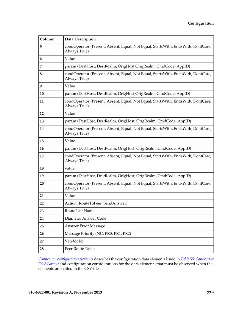
Data DescriptionColumn
condOperator (Present, Absent, Equal, Not Equal, StartsWith, EndsWith, DontCare,Always True)
5
Value6
param (DestHost, DestRealm, OrigHost,OrigRealm, CmdCode, AppID)7
condOperator (Present, Absent, Equal, Not Equal, StartsWith, EndsWith, DontCare,Always True)
8
Value9
param (DestHost, DestRealm, OrigHost,OrigRealm, CmdCode, AppID)10
condOperator (Present, Absent, Equal, Not Equal, StartsWith, EndsWith, DontCare,Always True)
11
Value12
param (DestHost, DestRealm, OrigHost, OrigRealm, CmdCode, AppID)13
condOperator (Present, Absent, Equal, Not Equal, StartsWith, EndsWith, DontCare,Always True)
14
Value15
param (DestHost, DestRealm, OrigHost, OrigRealm, CmdCode, AppID)16
condOperator (Present, Absent, Equal, Not Equal, StartsWith, EndsWith, DontCare,Always True)
17
value18
param (DestHost, DestRealm, OrigHost, OrigRealm, CmdCode, AppID)19
condOperator (Present, Absent, Equal, Not Equal, StartsWith, EndsWith, DontCare,Always True)
20
Value21
Action (RouteToPeer, SendAnswer)22
Route List Name23
Diameter Answer Code24
Answer Error Message25
Message Priority (NC, PR0, PR1, PR2)26
Vendor Id27
Peer Route Table28
Connection configuration elements describes the configuration data elements listed in Table 55: ConnectionCSV Format and configuration considerations for the data elements that must be observed when theelements are edited in the CSV files.
229910-6822-001 Revision A, November 2013
Configuration
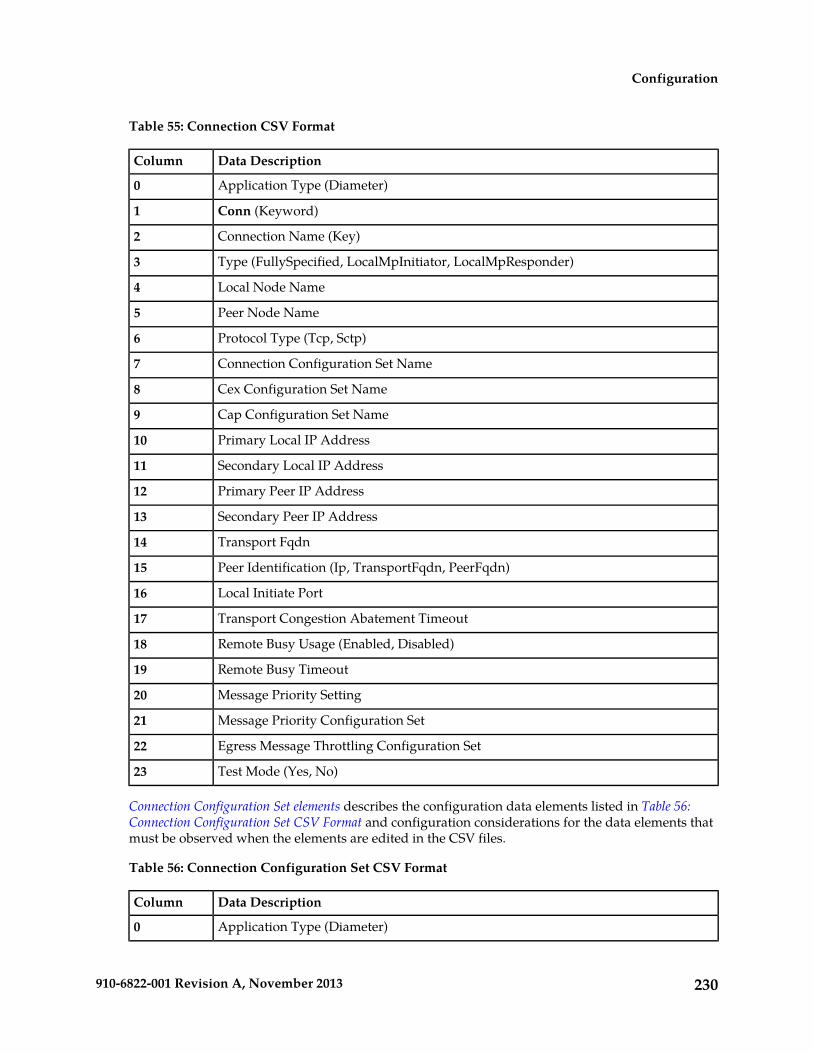
Table 55: Connection CSV Format
Data DescriptionColumn
Application Type (Diameter)0
Conn (Keyword)1
Connection Name (Key)2
Type (FullySpecified, LocalMpInitiator, LocalMpResponder)3
Local Node Name4
Peer Node Name5
Protocol Type (Tcp, Sctp)6
Connection Configuration Set Name7
Cex Configuration Set Name8
Cap Configuration Set Name9
Primary Local IP Address10
Secondary Local IP Address11
Primary Peer IP Address12
Secondary Peer IP Address13
Transport Fqdn14
Peer Identification (Ip, TransportFqdn, PeerFqdn)15
Local Initiate Port16
Transport Congestion Abatement Timeout17
Remote Busy Usage (Enabled, Disabled)18
Remote Busy Timeout19
Message Priority Setting20
Message Priority Configuration Set21
Egress Message Throttling Configuration Set22
Test Mode (Yes, No)23
Connection Configuration Set elements describes the configuration data elements listed in Table 56:Connection Configuration Set CSV Format and configuration considerations for the data elements thatmust be observed when the elements are edited in the CSV files.
Table 56: Connection Configuration Set CSV Format
Data DescriptionColumn
Application Type (Diameter)0
230910-6822-001 Revision A, November 2013
Configuration

Data DescriptionColumn
ConnCfgSet (Keyword)1
ConnCfgSet Name (Key)2
retransInitialTimeout3
retransMinTimeout4
retransMaxTimeout5
retransMaxTimeoutInit6
retransPathFailure7
retransAssocFailure8
retransInitFailure9
sackDelay10
heartbeatInterval11
sctpSockSendSize12
sctpSockReceiveSize13
sctpNumInboundStreams14
sctpNumOutboundStreams15
burstMax16
sctpDatagramBundlingEnabled (Yes, No)17
tcpSockSendSize18
tcpSockRecvSize19
tcTimer20
twinitTimer21
tdpxTimer22
tcexTimer23
nagleEnabled (Yes, No)24
provingTimeout25
provingDwrsToSend26
provingMode (Always, Suspect, Never)27
pendTransPerConn28
Reroute On Answer configuration elements describes the configuration data elements listed in Table 57:Reroute on Answer CSV Format and configuration considerations for the data elements that must beobserved when the elements are edited in the CSV files.
231910-6822-001 Revision A, November 2013
Configuration
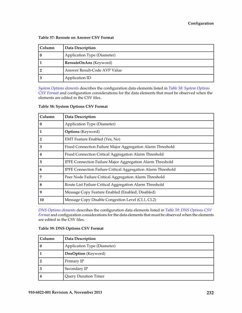
Table 57: Reroute on Answer CSV Format
Data DescriptionColumn
Application Type (Diameter)0
RerouteOnAns (Keyword)1
Answer Result-Code AVP Value2
Application ID3
System Options elements describes the configuration data elements listed in Table 58: System OptionsCSV Format and configuration considerations for the data elements that must be observed when theelements are edited in the CSV files.
Table 58: System Options CSV Format
Data DescriptionColumn
Application Type (Diameter)0
Options (Keyword)1
EMT Feature Enabled (Yes, No)2
Fixed Connection Failure Major Aggregation Alarm Threshold3
Fixed Connection Critical Aggregation Alarm Threshold4
IPFE Connection Failure Major Aggregation Alarm Threshold5
IPFE Connection Failure Critical Aggregation Alarm Threshold6
Peer Node Failure Critical Aggregation Alarm Threshold7
Route List Failure Critical Aggregation Alarm Threshold8
Message Copy Feature Enabled (Enabled, Disabled)9
Message Copy Disable Congestion Level (CL1, CL2)10
DNS Options elements describes the configuration data elements listed in Table 59: DNS Options CSVFormat and configuration considerations for the data elements that must be observed when the elementsare edited in the CSV files.
Table 59: DNS Options CSV Format
Data DescriptionColumn
Application Type (Diameter)0
DnsOption (Keyword)1
Primary IP2
Secondary IP3
Query Duration Timer4
232910-6822-001 Revision A, November 2013
Configuration

CEX Configuration Set elements describes the configuration data elements listed in Table 60: CEXConfiguration Set CSV Format and configuration considerations for the data elements that must beobserved when the elements are edited in the CSV files.
Table 60: CEX Configuration Set CSV Format
Data DescriptionColumn
Application Type (Diameter)0
CexCfgSet (Keyword)1
Name2
Selected Application ID [1]3
Selected Type [1]4
Selected Vendor ID[1]5
(repeated x 10)
Selected Application ID [10]30
Selected Type [10]31
Selected Vendor ID [10]32
Must Application ID [1]33
Must Type [1]34
Must Vendor ID[1]35
(repeated x 10)
Must Application ID[10]60
Must Type [10]61
Must Vendor ID[10]62
Vendor ID [1]63
(repeated x 10)
Vendor ID [10]72
Capacity Configuration Set elements describes the configuration data elements listed in Table 61: CapacityConfiguration Set CSV Format and configuration considerations for the data elements that must beobserved when the elements are edited in the CSV files.
Table 61: Capacity Configuration Set CSV Format
Data DescriptionColumn
Application Type (Diameter)0
CapCfgSet (Keyword)1
Capacity Configuration Set Name (Key)2
233910-6822-001 Revision A, November 2013
Configuration

Data DescriptionColumn
Reserved Ingress MPS3
Maximum Ingress MPS4
Ingress MPS Minor Alarm Threshold5
Ingress MPS Major Alarm Threshold6
Reserved Ingress MPS Abatement Time7
Application Routing Rule configuration elements describes the configuration data elements listed in Table62: AppRouteRule CSV Format and configuration considerations for the data elements that must beobserved when the elements are edited in the CSV files.
Table 62: AppRouteRule CSV Format
Data DescriptionColumn
Application Type (Diameter)0
AppRouteRule (Keyword)1
Name (Key)2
Priority3
param (DestHost, DestRealm, OrigHost,OrigRealm, CmdCode AppID)4
condOperator (Present, Absent, Equal, Not Equal, StartsWith, EndsWith, DontCare,Always True)
5
Value6
param (DestHost, DestRealm, OrigHost,OrigRealm, CmdCode AppID)7
condOperator (Present, Absent, Equal, Not Equal, StartsWith, EndsWith, DontCare,Always True)
8
Value9
param (DestHost, DestRealm, OrigHost,OrigRealm, CmdCode AppID)10
condOperator (Present, Absent, Equal, Not Equal, StartsWith, EndsWith, DontCare,Always True)
11
Value12
param (DestHost, DestRealm, OrigHost,OrigRealm, CmdCode AppID)13
condOperator (Present, Absent, Equal, Not Equal, StartsWith, EndsWith, DontCare,Always True)
14
Value15
param (DestHost, DestRealm, OrigHost,OrigRealm, CmdCode AppID)16
condOperator (Present, Absent, Equal, Not Equal, StartsWith, EndsWith, DontCare,Always True)
17
234910-6822-001 Revision A, November 2013
Configuration

Data DescriptionColumn
value18
param (DestHost, DestRealm, OrigHost,OrigRealm, CmdCode AppID)19
condOperator (Present, Absent, Equal, Not Equal, StartsWith, EndsWith, DontCare,Always True)
20
Value21
Application Name22
Application Route Table23
Application Ids elements describes the configuration data elements listed in Table 63: Application ID CSVFormat and configuration considerations for the data elements that must be observed when the elementsare edited in the CSV files.
Table 63: Application ID CSV Format
Data DescriptionColumn
Application Type (Diameter)0
Appids (Keyword)1
Application ID2
Name3
Routing Option Set4
Pending Answer Timer5
Peer Route Table6
Application Route Table7
CEX Parameters elements describes the configuration data elements listed in Table 64: CEX ParametersCSV Format and configuration considerations for the data elements that must be observed when theelements are edited in the CSV files.
Table 64: CEX Parameters CSV Format
Data DescriptionColumn
Application Type (Diameter)0
CexParameters (Keyword)1
Application ID2
Vendor ID3
Pending Answer Timers elements describes the configuration data elements listed in Table 65: PendingAnswer Timer CSV Format and configuration considerations for the data elements that must be observedwhen the elements are edited in the CSV files.
235910-6822-001 Revision A, November 2013
Configuration

Table 65: Pending Answer Timer CSV Format
Data DescriptionColumn
Application Type (Diameter)0
PendingAnswerTimer (Keyword)1
Name2
Timer3
Routing Option Sets elements describes the configuration data elements listed in Table 66: Routing OptionSet CSV Format and configuration considerations for the data elements that must be observed whenthe elements are edited in the CSV files.
Table 66: Routing Option Set CSV Format
Data DescriptionColumn
Application Type (Diameter)0
RoutingOptionSet (Keyword)1
Name2
Maximum Per Message Forwarding Allowed3
Transaction Lifetime4
Pending Answer Timer5
Resource Exhausted Action6
Resource Exhausted Result Code7
Resource Exhausted Error Message8
Resource Exhausted Vendor Id9
No Peer Response Action10
No Peer Response Result Code11
No Peer Response Error Message12
No Peer Response Vendor Id13
Connection Failure Action14
Connection Failure Result Code15
Connection Failure Error Message16
Connection Failure Vendor Id17
Connection Congestion Action18
Connection Congestion Result Code19
Connection Congestion Error Message20
236910-6822-001 Revision A, November 2013
Configuration

Data DescriptionColumn
Connection Congestion Vendor Id21
Peer Route Tables elements describes the configuration data elements listed in Table 67: Peer Route TableCSV Format and configuration considerations for the data elements that must be observed when theelements are edited in the CSV files.
Table 67: Peer Route Table CSV Format
Data DescriptionColumn
Application Type (Diameter)0
PeerRouteTable (Keyword)1
Name (Key)2
Message Priority Configuration Set elements describes the configuration data elements listed in Table 68:Message Priority Configuration Set CSV Format and configuration considerations for the data elementsthat must be observed when the elements are edited in the CSV files.
Table 68: Message Priority Configuration Set CSV Format
Data DescriptionColumn
Application Type (Diameter)0
MsgPriorityCfgSet (Keyword)1
Name2
applId[1]3
cmdCode[1]4
msgPriority[1]5
(repeated x 50)
applId[50]151
cmdCode[50]152
msgPriority[50]153
Egress Message Throttling Configuration Set elements describes the configuration data elements listed inTable 68: Message Priority Configuration Set CSV Format and configuration considerations for the dataelements that must be observed when the elements are edited in the CSV files.
Table 69: Message Throttling Configuration Set CSV Format
Data DescriptionColumn
Application Type (Diameter)0
MsgThrottlingCfgSet (Keyword)1
237910-6822-001 Revision A, November 2013
Configuration
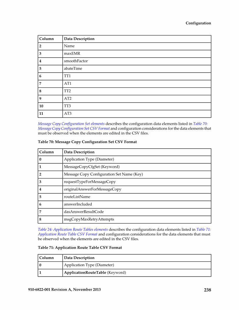
Data DescriptionColumn
Name2
maxEMR3
smoothFactor4
abateTime5
TT16
AT17
TT28
AT29
TT310
AT311
Message Copy Configuration Set elements describes the configuration data elements listed in Table 70:Message Copy Configuration Set CSV Format and configuration considerations for the data elements thatmust be observed when the elements are edited in the CSV files.
Table 70: Message Copy Configuration Set CSV Format
Data DescriptionColumn
Application Type (Diameter)0
MessageCopyCfgSet (Keyword)1
Message Copy Configuration Set Name (Key)2
requestTypeForMessageCopy3
originalAnswerForMessageCopy4
routeListName5
answerIncluded6
dasAnswerResultCode7
msgCopyMaxRetryAttempts8
Table 24: Application Route Tables elements describes the configuration data elements listed in Table 71:Application Route Table CSV Format and configuration considerations for the data elements that mustbe observed when the elements are edited in the CSV files.
Table 71: Application Route Table CSV Format
Data DescriptionColumn
Application Type (Diameter)0
ApplicationRouteTable (Keyword)1
238910-6822-001 Revision A, November 2013
Configuration
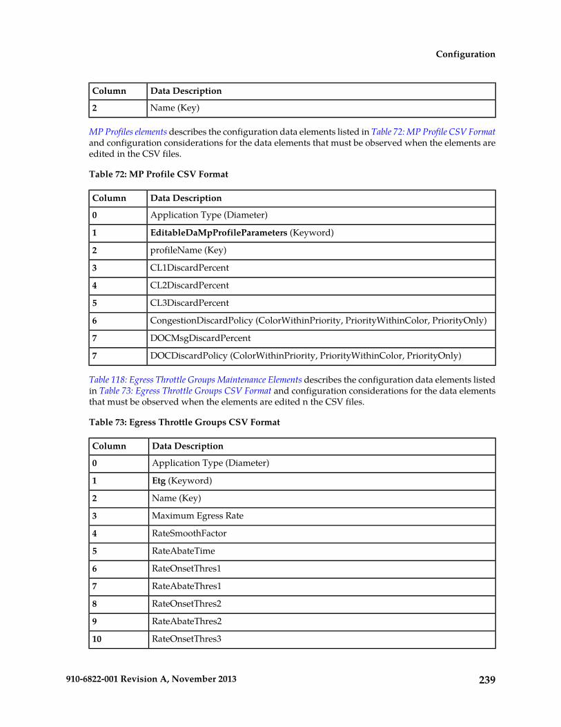
Data DescriptionColumn
Name (Key)2
MP Profiles elements describes the configuration data elements listed in Table 72: MP Profile CSV Formatand configuration considerations for the data elements that must be observed when the elements areedited in the CSV files.
Table 72: MP Profile CSV Format
Data DescriptionColumn
Application Type (Diameter)0
EditableDaMpProfileParameters (Keyword)1
profileName (Key)2
CL1DiscardPercent3
CL2DiscardPercent4
CL3DiscardPercent5
CongestionDiscardPolicy (ColorWithinPriority, PriorityWithinColor, PriorityOnly)6
DOCMsgDiscardPercent7
DOCDiscardPolicy (ColorWithinPriority, PriorityWithinColor, PriorityOnly)7
Table 118: Egress Throttle Groups Maintenance Elements describes the configuration data elements listedin Table 73: Egress Throttle Groups CSV Format and configuration considerations for the data elementsthat must be observed when the elements are edited n the CSV files.
Table 73: Egress Throttle Groups CSV Format
Data DescriptionColumn
Application Type (Diameter)0
Etg (Keyword)1
Name (Key)2
Maximum Egress Rate3
RateSmoothFactor4
RateAbateTime5
RateOnsetThres16
RateAbateThres17
RateOnsetThres28
RateAbateThres29
RateOnsetThres310
239910-6822-001 Revision A, November 2013
Configuration

Data DescriptionColumn
RateAbateThres311
Maximum Number of Pending Transactions12
PendTransAbateTime13
PendTransOnsetThres114
PendTransAbateThres115
PendTransOnsetThres216
PendTransAbateThres217
PendTransOnsetThres318
PendTransAbateThres319
Peers20
repeated x 128
Conns147
repeated x 128
Table 7: MCC Ranges elements describes the configuration data elements listed in Table 74: Reserved MCCRanges CSV Format and configuration considerations for the data elements that must be observed whenthe elements are edited in the CSV files.
Table 74: Reserved MCC Ranges CSV Format
Data DescriptionColumn
Application Type (Diameter)0
ReservedMccRanges (Keyword)1
startMccRange2
endMccRange3
Table 6: Command Codes elements describes the configuration data elements listed in Table 75: CommandCode CSV Format and configuration considerations for the data elements that must be observed whenthe elements are edited in the CSV files.
Table 75: Command Code CSV Format
Data DescriptionColumn
Application Type (Diameter)0
CmdCodes (Keyword)1
cmdCode2
name3
240910-6822-001 Revision A, November 2013
Configuration

Table 41: Trusted Network Lists elements describes the configuration data elements listed in Table 76:Trusted Network List CSV Format and configuration considerations for the data elements that must beobserved when the elements are edited in the CSV files.
Table 76: Trusted Network List CSV Format
Data DescriptionColumn
Application Type (Diameter)0
TrustedNetworkList (Keyword)1
Name (Key)2
trustedRealm [1]3
(repeated x 100)
Table 42: Path Topology Hiding Configuration Sets Elements describes the configuration data elementslisted in Table 77: Path Topology Hiding Configuration Set CSV Format and configuration considerationsfor the data elements that must be observed when the elements are edited in the CSV files.
Table 77: Path Topology Hiding Configuration Set CSV Format
Data DescriptionColumn
Application Type (Diameter)0
PathTopologyHidingCfgSet (Keyword)1
Name (Key)2
hostnameSuffix3
(repeated x 10)
pseudoRouteRecord13
pseudoProxy14
encryptionKey15
S6a/S6d HSS Topology Hiding Configuration Set elements describes the configuration data elements listedin Table 78: S6a/S6d HSS Topology Hiding Configuration Set CSV Format and configuration considerationsfor the data elements that must be observed when the elements are edited in the CSV files.
Table 78: S6a/S6d HSS Topology Hiding Configuration Set CSV Format
Data DescriptionColumn
Application Type0
HssTopologyHidingCfgSet (Keyword)1
Name (Key)2
pseudoHssHostname3
241910-6822-001 Revision A, November 2013
Configuration

MME/SGSN Topology Hiding Configuration Set elements describes the configuration data elements listedin Table 79: MME/SGSN Topology Hiding Configuration Set CSV Format and configuration considerationsfor the data elements that must be observed when the elements are edited in the CSV files.
Table 79: MME/SGSN Topology Hiding Configuration Set CSV Format
Data DescriptionColumn
Application Type (Diameter )0
MmeTopologyHidingCfgSet (Keyword)1
Name (Key)2
count3
randomizeCount4
autoGenerate5
prefix6
suffix7
length8
Action (SendAnswer, Forward, Abandon)9
resultCode10
vendorId11
errMsg12
actualHostname[1]13
pseudoHostname114
pseudoHostname215
pseudoHostname316
(combination of actual and pseudo hostnames repeated x 300)
Table 45: Protected Network Configuration Elements describes the configuration data elements listed inTable 80: Protected Network CSV Format and configuration considerations for the data elements thatmust be observed when the elements are edited in the CSV files.
Table 80: Protected Network CSV Format
Data DescriptionColumn
Application Type (Diameter)0
ProtectedNetwork (Keyword)1
protectedRealm (Key)2
trustedNetList3
pathTopologyHidingCfgSet4
242910-6822-001 Revision A, November 2013
Configuration

Data DescriptionColumn
mmeTopologyHidingCfgSet5
hssTopologyHidingCfgSet6
Range-Based Address Resolution (RBAR) CSV File Formats
The following tables describe the CSV file content and attribute column positions for all configurationdata supported by the RBAR Application Type.
Note: Address Individual and Address Range elements are in different CSV files for performancereasons.
"Applications configuration elements" in the RBAR Help describes the configuration data elementslisted in Table 81: Supported Application CSV Format and configuration considerations for the dataelements that must be observed when the elements are edited in the CSV files.
Table 81: Supported Application CSV Format
Data DescriptionColumn
Application Type (Rbar)0
SuppAppl (Keyword)1
Application ID2
Routing Mode (Proxy)3
"Addresses configuration elements" in the RBAR Help describes the configuration data elements listedin Table 82: Address Individual CSV Format and configuration considerations for the data elements thatmust be observed when the elements are edited in the CSV files.
Table 82: Address Individual CSV Format
Data DescriptionColumn
Application Type (Rbar)0
AddressIndv (Keyword)1
Table Name2
Address3
Destination4
Pfx Length5
Routing Entity (Imsi, Msisdn, Impi, Impu, Ipv4, Ipv6PfxAddr, Unsigned16)6
Old Table Name7
Old Address8
Old Pfx Length9
243910-6822-001 Revision A, November 2013
Configuration

"Addresses configuration elements" in the RBAR Help describes the configuration data elements listedin Table 82: Address Individual CSV Format and configuration considerations for the data elements thatmust be observed when the elements are edited in the CSV files.
Table 83: Address Range CSV Format
Data DescriptionColumn
Application Type (Rbar)0
AddressRange (Keyword)1
Table Name2
Start Address3
End Address4
Destination5
Pfx Length6
Old Table Name7
Old Start Address8
Old Pfx Length9
"Address Tables configuration elements" in the RBAR Help describes the configuration data elementslisted in Table 84: Address Table CSV Format and configuration considerations for the data elementsthat must be observed when the elements are edited in the CSV files.
Table 84: Address Table CSV Format
Data DescriptionColumn
Application Type (Rbar)0
AddressTable (Keyword)1
Name2
Comment3
Routing Entity (Imsi, Msisdn, Impi, Impu, Ipv4, Ipv6PfxAddr, Unsigned16)4
"Destinations configuration elements" in the RBAR Help describes the configuration data elementslisted in Table 85: Destination Table CSV Format and configuration considerations for the data elementsthat must be observed when the elements are edited in the CSV files.
Table 85: Destination Table CSV Format
Data DescriptionColumn
Application Type (Rbar)0
Destination (Keyword)1
244910-6822-001 Revision A, November 2013
Configuration

Data DescriptionColumn
Name2
Realm3
Fqdn4
Avp Insertion (No, Yes)5
"Exceptions configuration elements" in the RBAR Help describes the configuration data elements listedin Table 86: Routing Exception CSV Format and configuration considerations for the data elements thatmust be observed when the elements are edited in the CSV files.
Table 86: Routing Exception CSV Format
Data DescriptionColumn
Application Type (Rbar)0
RoutingException (Keyword)1
Application ID2
Exception Type (UnknownCmdCode, NoRoutingEntityAddress, NoDrtEntry)3
Action (FwdUnchanged, FwdToDest, SendAnswer, SendAnsExp)4
Destination Name5
Answer Result Code6
Vendor ID7
Error Message8
"Address Resolutions configuration elements" in the RBAR Help describes the configuration dataelements listed in Table 87: Address Resolution CSV Format and configuration considerations for thedata elements that must be observed when the elements are edited in the CSV files.
Table 87: Address Resolution CSV Format
Data DescriptionColumn
Application Type (Rbar)0
Resolution (Keyword)1
Application ID2
CMD Code3
CMD Name4
Routing Entity 1 (Imsi, Msisdn, Impi, Impu, Ipv4, Ipv6PfxAddr, Unsigned16)5
Re 1 Avp 1 (PublicIdentity, SvcInfoSubscrId0, SvcInfoSubscrId1, SvcInfoSubscrId2,SvcInfoSubscrId3, SvcInfoSubscrId4, SubscriptionId0, SubscriptionId1, SubscriptionId2,
6
245910-6822-001 Revision A, November 2013
Configuration

Data DescriptionColumnSubscriptionId3, SubscriptionId4, UserIdentityMsisdn, UserIdentityPublic, UserName,FramedIpAddress, FramedIpv6Prefix, SvcInfoPsInfo3gppcc, Unprovisioned)
Re 1 Avp 2 (PublicIdentity, SvcInfoSubscrId0, SvcInfoSubscrId1, SvcInfoSubscrId2,SvcInfoSubscrId3, SvcInfoSubscrId4, SubscriptionId0, SubscriptionId1, SubscriptionId2,
7
SubscriptionId3, SubscriptionId4, UserIdentityMsisdn, UserIdentityPublic, UserName,FramedIpAddress, FramedIpv6Prefix, SvcInfoPsInfo3gppcc, Unprovisioned)
Re 1 Address Table Name8
Routing Entity 2 (Imsi, Msisdn, Impi, Impu, Ipv4, Ipv6PfxAddr, Unsigned16)9
Re 2 Avp 1 (PublicIdentity, SvcInfoSubscrId0, SvcInfoSubscrId1, SvcInfoSubscrId2,SvcInfoSubscrId3, SvcInfoSubscrId4, SubscriptionId0, SubscriptionId1, SubscriptionId2,
10
SubscriptionId3, SubscriptionId4, UserIdentityMsisdn, UserIdentityPublic, UserName,FramedIpAddress, FramedIpv6Prefix, SvcInfoPsInfo3gppcc, Unprovisioned)
Re 2 Avp 2 (PublicIdentity, SvcInfoSubscrId0, SvcInfoSubscrId1, SvcInfoSubscrId2,SvcInfoSubscrId3, SvcInfoSubscrId4, SubscriptionId0, SubscriptionId1, SubscriptionId2,
11
SubscriptionId3, SubscriptionId4, UserIdentityMsisdn, UserIdentityPublic, UserName,FramedIpAddress, FramedIpv6Prefix, SvcInfoPsInfo3gppcc, Unprovisioned)
Re 2 Address Table name12
"System Options elements" in the RBAR Help describes the configuration data elements listed in Table88: Option CSV Format and configuration considerations for the data elements that must be observedwhen the elements are edited in the CSV files.
Table 88: Option CSV Format
Data DescriptionColumn
Application Type (Rbar)0
Option (Keyword)1
Uri Supported (No, Yes)2
RemoveDestHost (No, Yes)3
Exclude Space (No, Yes)4
Allow Subsequent DSR App Invoc (No, Yes)5
Realm6
Fqdn7
Resource Exhaustion Error Code8
Resource Exhaustion Error Message9
Resource Exhaustion Vendor ID10
Unavailable Application Action (ContinueRouting, DefaultRoute, SendAnswer,SendAnsExp)
11
246910-6822-001 Revision A, November 2013
Configuration

Data DescriptionColumn
Unavailable Application Route List12
Unavailable Application Result Code13
Unavailable Application Error Message14
Unavailable Application Vendor ID15
ASCII Exluded List [0]16
(repeated x 20) . . .
ASCII Excluded List [19]35
TBCD Excluded List [0]36
(repeated x 5) . . .
TBCD Excluded List [4]40
Full Address-Based Resolution (FABR) CSV File Formats
The following tables describe the CSV file content and attribute column positions for all configurationdata supported by the FABR Application Type.
"Applications configuration elements" in the FABR Help describes the configuration data elementslisted in Table 81: Supported Application CSV Format and configuration considerations for the dataelements that must be observed when the elements are edited in the CSV files.
Table 89: Supported Application CSV Format
Data DescriptionColumn
Application Type (Fabr)0
SuppAppl (Keyword)1
Application ID2
Routing Mode (Proxy)3
"Exceptions configuration elements" in the FABR Help describes the configuration data elements listedin Table 86: Routing Exception CSV Format and configuration considerations for the data elements thatmust be observed when the elements are edited in the CSV files.
Table 90: Routing Exception CSV Format
Data DescriptionColumn
Application Type (FABR)0
RoutingException (Keyword)1
Application ID2
Exception Type (UnknownCmdCode, NoRoutingEntityAddress, NoAddrMatch,DpErrors, DpCongestion)
3
247910-6822-001 Revision A, November 2013
Configuration

Data DescriptionColumn
Action (FwdUnchanged, FwdToDest, SendAnswer, SendAnsExp)4
Destination Name5
Answer Result Code6
Vendor ID7
Error Message8
"Destinations configuration elements" in the FABR Help describes the configuration data elementslisted in Table 85: Destination Table CSV Format and configuration considerations for the data elementsthat must be observed when the elements are edited in the CSV files.
Table 91: Default Destination Table CSV Format
Data DescriptionColumn
Application Type (Fabr)0
Destination (Keyword)1
Name2
Realm3
Fqdn4
"Address Resolutions configuration elements" in the FABR Help describes the configuration dataelements listed in Table 87: Address Resolution CSV Format and configuration considerations for thedata elements that must be observed when the elements are edited in the CSV files.
Table 92: Address Resolution CSV Format
Data DescriptionColumn
Application Type (Fabr)0
Resolution (Keyword)1
Application ID2
CMD Code3
Routing Entity 1 (Imsi, Msisdn, Impi, Impu)4
Re 1 Avp 1 (PublicIdentity, SvcInfoSubscrId0, SvcInfoSubscrId1, SvcInfoSubscrId2,SvcInfoSubscrId3, SubscriptionId0, SubscriptionId1, SubscriptionId2, SubscriptionId3,UserIdentityMsisdn, UserIdentityPublic, UserName, WildCardedPubIdnty)
5
Re 1 Avp 2 (PublicIdentity, SvcInfoSubscrId0, SvcInfoSubscrId1, SvcInfoSubscrId2,SvcInfoSubscrId3, SubscriptionId0, SubscriptionId1, SubscriptionId2, SubscriptionId3,UserIdentityMsisdn, UserIdentityPublic, UserName, WildCardedPubIdnty)
6
Re 1 Destination Type (ImsHss, LteHss, Pcrf, Ocs, Ofcs, Aaa, UserDefined1,UserDefined 2)
7
248910-6822-001 Revision A, November 2013
Configuration

Data DescriptionColumn
Routing Entity 2 (Imsi, Msisdn, Impi, Impu)8
Re 2 Avp 1 (PublicIdentity, SvcInfoSubscrId0, SvcInfoSubscrId1, SvcInfoSubscrId2,SvcInfoSubscrId3, SubscriptionId0, SubscriptionId1, SubscriptionId2, SubscriptionId3,UserIdentityMsisdn, UserIdentityPublic, UserName, WildCardedPubIdnty)
9
Re 2 Avp 2 (PublicIdentity, SvcInfoSubscrId0, SvcInfoSubscrId1, SvcInfoSubscrId2,SvcInfoSubscrId3, SubscriptionId0, SubscriptionId1, SubscriptionId2, SubscriptionId3,UserIdentityMsisdn, UserIdentityPublic, UserName, WildCardedPubIdnty)
10
Re 2 Destination Type (ImsHss, LteHss, Pcrf, Ocs, Ofcs, Aaa, UserDefined1,UserDefined 2)
11
"System Options elements" in the FABR Help describes the configuration data elements listed in Table88: Option CSV Format and configuration considerations for the data elements that must be observedwhen the elements are edited in the CSV files.
Table 93: Option CSV Format
Data DescriptionColumn
Application Type (Fabr)0
Option (Keyword)1
RemoveDestHost (No, Yes)2
Exclude Space (No, Yes)3
Allow Subsequent DSR App Invoc (No, Yes)4
Realm5
Fqdn6
Resource Exhaustion Error Code7
Resource Exhaustion Error Message8
Resource Exhaustion Vendor ID9
Unavailable Application Action (ContinueRouting, DefaultRoute, SendAnswer,SendAnsExp)
10
Unavailable Application Route List11
Unavailable Application Result Code12
Unavailable Application Error Message13
Unavailable Application Vendor ID14
ASCII Excluded List [0]15
(repeated x 20) . . .
ASCII Excluded List [19]33
249910-6822-001 Revision A, November 2013
Configuration
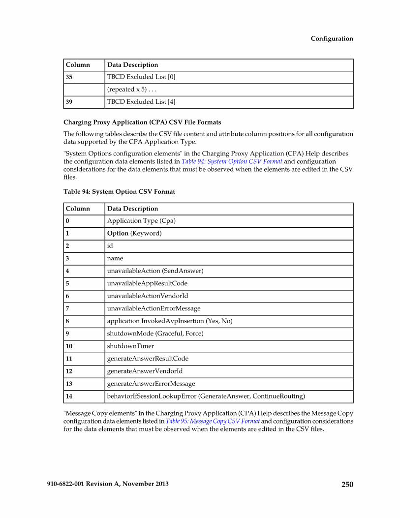
Data DescriptionColumn
TBCD Excluded List [0]35
(repeated x 5) . . .
TBCD Excluded List [4]39
Charging Proxy Application (CPA) CSV File Formats
The following tables describe the CSV file content and attribute column positions for all configurationdata supported by the CPA Application Type.
"System Options configuration elements" in the Charging Proxy Application (CPA) Help describesthe configuration data elements listed in Table 94: System Option CSV Format and configurationconsiderations for the data elements that must be observed when the elements are edited in the CSVfiles.
Table 94: System Option CSV Format
Data DescriptionColumn
Application Type (Cpa)0
Option (Keyword)1
id2
name3
unavailableAction (SendAnswer)4
unavailableAppResultCode5
unavailableActionVendorId6
unavailableActionErrorMessage7
application InvokedAvpInsertion (Yes, No)8
shutdownMode (Graceful, Force)9
shutdownTimer10
generateAnswerResultCode11
generateAnswerVendorId12
generateAnswerErrorMessage13
behaviorIfSessionLookupError (GenerateAnswer, ContinueRouting)14
"Message Copy elements" in the Charging Proxy Application (CPA) Help describes the Message Copyconfiguration data elements listed in Table 95: Message Copy CSV Format and configuration considerationsfor the data elements that must be observed when the elements are edited in the CSV files.
250910-6822-001 Revision A, November 2013
Configuration

Table 95: Message Copy CSV Format
Data DescriptionColumn
Application Type (Cpa)0
Messagecopy (Keyword)1
messageCopyStatus2
messageCopyRouteList13
messageCopyRouteList24
messageCopyRouteList35
messageCopyRouteList46
messageCopyRouteList57
messageCopyRouteList68
messageCopyRouteList79
messageCopyRouteList810
messageCopyRouteList911
messageCopyRouteList1012
calledStationIdString113
calledStationIdString214
calledStationIdString315
calledStationIdString416
"SBR elements" in the Charging Proxy Application (CPA) Help describes the Session Binding Repository(SBR) configuration data elements listed in Table 96: SBR CSV Format and configuration considerationsfor the data elements that must be observed when the elements are edited in the CSV files.
Table 96: SBR CSV Format
Data DescriptionColumn
Application Type (Sbr)0
Sbrconfig (Keyword)1
sbdbAuditStartTime2
sbdbAuditStopTime3
staleSbdbSessionBindingAge4
maximumActiveSessionBindings5
mostlyStalePercent6
251910-6822-001 Revision A, November 2013
Configuration

IP Front End CSV File Formats
The following tables describe the CSV file content and attribute column positions for all configurationdata supported by the IP Front End (IPFE) Application Type.
"Configuration Options elements" in the IPFE Help describes the configuration data elements listedin Table 97: IPFE IpfeOption CSV Format and configuration considerations for the data elements thatmust be observed when the elements are edited in the CSV files.
Table 97: IPFE IpfeOption CSV Format
Data DescriptionColumn
Application Type (Ipfe)0
Options (Keyword)1
Ipfe1IpAddress2
Ipfe2IpAddress3
Ipfe3IpAddress4
Ipfe4IpAddress5
StatSyncTcpPort6
StateSyncReconnectS7
ApplicationMinPort8
ApplicationMaxPort9
RejectOption (tcpreset, drop, icmphostunreachable, icmpportunreachable,icmpadminprohibited)
10
SctpRejectOption (drop, icmphostunreachable, icmpportunreachable,icmpadminprohibited)
11
OverloadStart12
LeastLoadStart13
Accounting Support (enabled, disabled)14
ConnectTryPort15
ConnectTimeoutS16
ConnectTryIntervalS17
MonitorProtocol (tcpconnectonly, fullmonitoring, disabled)18
PacketRateLimit19
Tsa1DeleteAge20
Tsa1IPAddress21
Tsa1IPSecondaryAddress22
Tsa1IPSecondaryPreferredIpfe23
252910-6822-001 Revision A, November 2013
Configuration
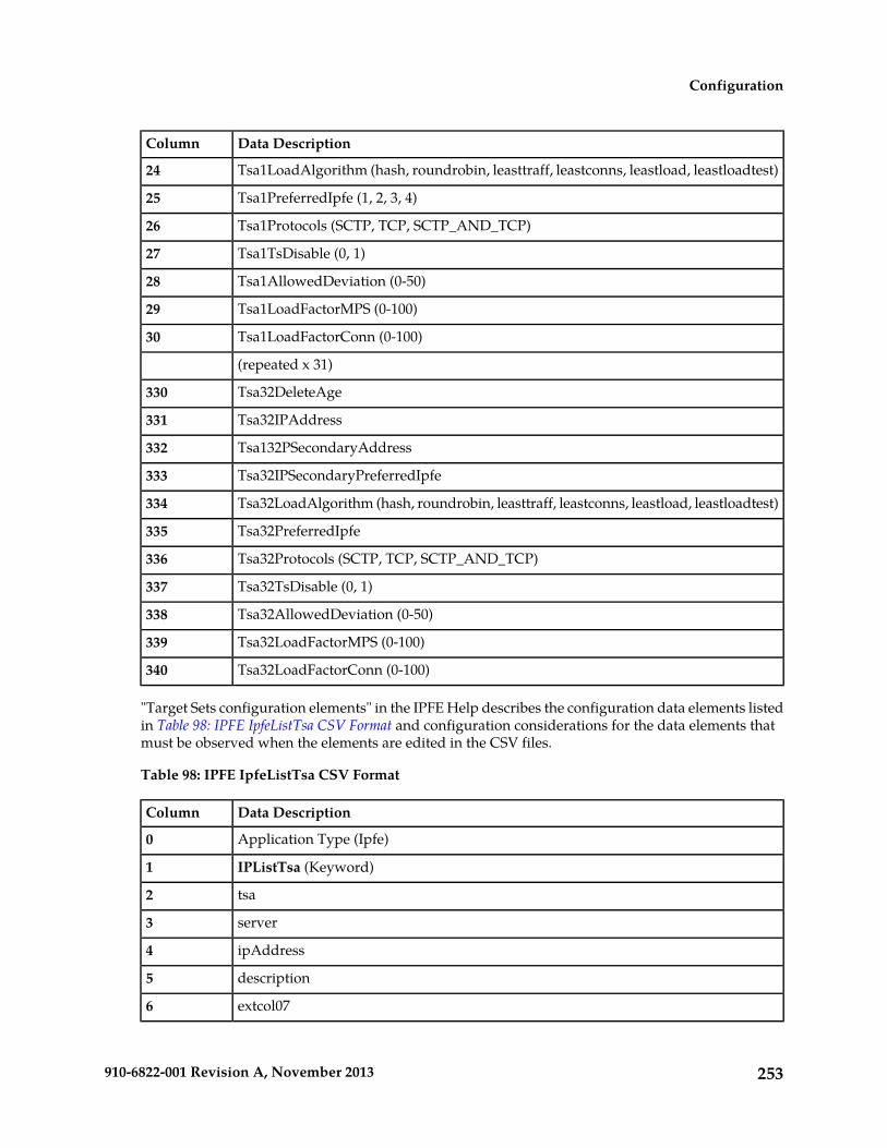
Data DescriptionColumn
Tsa1LoadAlgorithm (hash, roundrobin, leasttraff, leastconns, leastload, leastloadtest)24
Tsa1PreferredIpfe (1, 2, 3, 4)25
Tsa1Protocols (SCTP, TCP, SCTP_AND_TCP)26
Tsa1TsDisable (0, 1)27
Tsa1AllowedDeviation (0-50)28
Tsa1LoadFactorMPS (0-100)29
Tsa1LoadFactorConn (0-100)30
(repeated x 31)
Tsa32DeleteAge330
Tsa32IPAddress331
Tsa132PSecondaryAddress332
Tsa32IPSecondaryPreferredIpfe333
Tsa32LoadAlgorithm (hash, roundrobin, leasttraff, leastconns, leastload, leastloadtest)334
Tsa32PreferredIpfe335
Tsa32Protocols (SCTP, TCP, SCTP_AND_TCP)336
Tsa32TsDisable (0, 1)337
Tsa32AllowedDeviation (0-50)338
Tsa32LoadFactorMPS (0-100)339
Tsa32LoadFactorConn (0-100)340
"Target Sets configuration elements" in the IPFE Help describes the configuration data elements listedin Table 98: IPFE IpfeListTsa CSV Format and configuration considerations for the data elements thatmust be observed when the elements are edited in the CSV files.
Table 98: IPFE IpfeListTsa CSV Format
Data DescriptionColumn
Application Type (Ipfe)0
IPListTsa (Keyword)1
tsa2
server3
ipAddress4
description5
extcol076
253910-6822-001 Revision A, November 2013
Configuration

Policy Diameter Routing Agent CSV File Formats
The following tables describe the CSV file content and attribute column positions for all configurationdata supported by the Policy DRA Application Type.
"PCRFs elements" in the Policy DRA Help describes the configuration data elements listed in Table 99:PCRFs CSV Format and configuration considerations for the data elements that must be observed whenthe elements are edited in the CSV files.
Table 99: PCRFs CSV Format
Data DescriptionColumn
Application Type (Pdra)0
Pcrf (Keyword)1
PCRF Peer Node Name (Key)2
Comments3
"Binding Key Priority elements" in the Policy DRA Help describes the configuration data elementslisted in Table 100: Binding Key Priority CSV Format and configuration considerations for the dataelements that must be observed when the elements are edited in the CSV files.
Table 100: Binding Key Priority CSV Format
Data DescriptionColumn
Application Type (Pdra)0
BindPriority (Keyword)1
Priority 12
Binding Key Type 1 (Imsi, Msisdn, Ipv4, Ipv6)3
Priority 24
Binding Key Type 2 (Imsi, Msisdn, Ipv4, Ipv6)5
Priority 36
Binding Key Type 3 (Imsi, Msisdn, Ipv4, Ipv6)7
Priority 48
Binding Key Type 4 (Imsi, Msisdn, Ipv4, Ipv6)9
"Topology Hiding elements" in the Policy DRA Help describes the configuration data elements listedin Table 101: Policy DRA Topology Hiding CSV Format and configuration considerations for the dataelements that must be observed when the elements are edited in the CSV files.
Table 101: Policy DRA Topology Hiding CSV Format
Data DescriptionColumn
Application Type (Pdra)0
254910-6822-001 Revision A, November 2013
Configuration

Data DescriptionColumn
TopoHiding (Keyword)1
Policy Client Peer Node Name (Key)2
Comments3
"Site Options elements" and "Network-Wide Options elements" in the Policy DRA Help describes theconfiguration data elements listed in Table 102: Policy DRA Options CSV Format and configurationconsiderations for the data elements that must be observed when the elements are edited in the CSVfiles.
Table 102: Policy DRA Options CSV Format
Data DescriptionColumn
Application Type (Pdra)0
PdraOptions (Keyword)1
Policy DRA Mate DSR Peer Node Name2
Topology Hiding Enabled3
Topology Hiding Scope4
Topology Hiding FQDN5
Topology Hiding Realm6
Peer Route Table Name7
Policy DRA Unavailable (Relay, Discard)8
Default Stale Session Timeout9
Origin-Host and Origin-Realm for Policy DRA generated RAR messages (Local Host,PCRF)
10
Audit Default Max Frequency11
"Error Codes elements" in the Policy DRA Help describes the configuration data elements listed inTable 103: Error Codes CSV Format and configuration considerations for the data elements that mustbe observed when the elements are edited in the CSV files.
Table 103: Error Codes CSV Format
Data DescriptionColumn
Application Type (Pdra)0
ErrorCodes (Keyword)1
Error Condition (Key) (PdraUnavailCong, BindingNotFound,BindingFoundButUnableToRoute, SbrError, BindingKeyNotFoundCondition,BindingNotCreatedUnableToRoute)
2
255910-6822-001 Revision A, November 2013
Configuration

Data DescriptionColumn
Gx/Gxx Result Code3
Gx/Gxx Experimental Code4
Gx/Gxx Vendor ID5
Rx Result Code6
Rx Experimental Code7
Rx Vendor ID8
S9 Result Code9
S9 Experimental Code10
S9 Vendor ID11
All Result Code12
All Experimental Code13
All Vendor ID14
"Access Point Names elements" in the Policy DRA Help describes the configuration data elementslisted in Table 102: Policy DRA Options CSV Format and configuration considerations for the dataelements that must be observed when the elements are edited in the CSV files.
Table 104: Access Point Names CSV Format
Data DescriptionColumn
Application Type (Pdra)0
AccessPointName (Keyword)1
Access Point Name2
Stale Session Timeout3
"Alarm Settings elements" in the Policy DRA Help describes the configuration data elements listed inTable 105: Alarm Settings CSV Format and configuration considerations for the data elements that mustbe observed when the elements are edited in the CSV files.
Table 105: Alarm Settings CSV Format
Data DescriptionColumn
Application Type (Pdra)0
AlarmSupp (Keyword)1
Alarm Name 1 (PdraIngressMessageRate,OutstandingPdraSessionsThresholdExceeded)
2
Critical Alarm Threshold (Percent) 13
256910-6822-001 Revision A, November 2013
Configuration

Data DescriptionColumn
Suppress Critical 1 (Yes, No)4
Major Alarm Threshold (Percent) 15
Suppress Major 1 (Yes, No)6
Minor Alarm Threshold (Percent) 17
Suppress Minor 1 (Yes, No)8
Alarm Name 2 (PsbrActiveSessionsThreshold)9
Critical Alarm Threshold (Percent) 210
Suppress Critical 2 (Yes, No)11
Major Alarm Threshold (Percent) 212
Suppress Major 2 (Yes, No)13
Minor Alarm Threshold (Percent) 114
Suppress Minor 2 (Yes, No)15
Alarm Name 3 (PdraActiveBindingsThreshold)16
Critical Alarm Threshold (Percent) 317
Suppress Critical 3 (Yes, No)18
Major Alarm Threshold (Percent) 319
Suppress Major 3 (Yes, No)20
Minor Alarm Threshold (Percent) 321
Suppress Minor 3 (Yes, No)22
"Congestion Options elements" in the Policy DRA Help describes the configuration data elementslisted in Table 102: Policy DRA Options CSV Format and configuration considerations for the dataelements that must be observed when the elements are edited in the CSV files.
Table 106: Congestion Options CSV Format
Data DescriptionColumn
Application Type (Pdra)0
CongOptions (Keyword)1
Critical Alarm Onset Threshold 12
Critical Alarm Abatement Threshold 13
Major Alarm Onset Threshold 14
Major Alarm Abatement Threshold 15
Minor Alarm Onset Threshold 16
257910-6822-001 Revision A, November 2013
Configuration
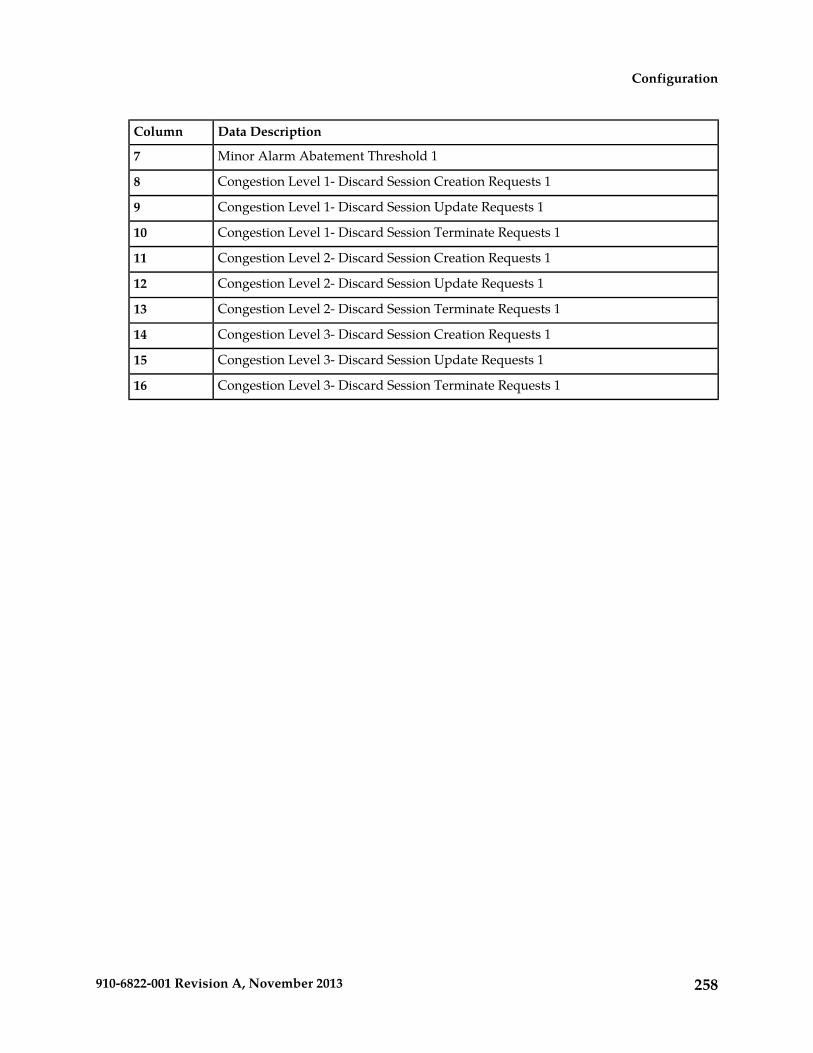
Data DescriptionColumn
Minor Alarm Abatement Threshold 17
Congestion Level 1- Discard Session Creation Requests 18
Congestion Level 1- Discard Session Update Requests 19
Congestion Level 1- Discard Session Terminate Requests 110
Congestion Level 2- Discard Session Creation Requests 111
Congestion Level 2- Discard Session Update Requests 112
Congestion Level 2- Discard Session Terminate Requests 113
Congestion Level 3- Discard Session Creation Requests 114
Congestion Level 3- Discard Session Update Requests 115
Congestion Level 3- Discard Session Terminate Requests 116
258910-6822-001 Revision A, November 2013
Configuration

Chapter
3Diameter Message Copy
The Diameter Message Copy function provides theability to forward a copy of a Diameter Request
Topics:
• Diameter Message Copy overview.....260 message, and optionally the Answer message,• Diameter Message Copy feature.....262 routed through the DSR to a Diameter Application
Server (a DAS Peer). Diameter Message Copy canbe triggered by a configuration or can be dictatedby a DSR Application.
259910-6822-001 Revision A, November 2013

Diameter Message Copy overview
For a message that was routed through the DSR, the Diameter Message Copy feature provides theability to forward a copy of the Diameter Request message, and optionally the Answer message, to aDiameter Application Server (a DAS Peer). Diameter Message Copy can be triggered by a configurationor can be dictated by a DSR Application.
Diameter Message Copy copies both Diameter Request and Answer messages as directed by one ormore Trigger Points within the DSR node. The Trigger Points can be any processing functions actingon the messages, including Diameter Mediation, DSR Applications, and Peer Routing Rules. MessageCopy Configuration Sets define the contents and conditions on which the copy needs to be performed.
Message Copy Configuration Sets provide a mechanism for determining the messages to be copied(Request or Answer), the Result-Code/Experimental Result-Code on which the Message Copy isinitiated, and number of retries to be made if the Message Copy attempt to DAS fails. The MessageCopy Trigger Point must specify a Message Copy Configuration Set when the message is marked forcopying.
Trigger Points mark the message ready for copy, based on the circumstances and requirements specificto the Trigger Points. The Diameter Message Copy feature determines the condition at which the copyneeds to made and ensures that the copied message is delivered to DAS. A triggering condition orrule can be configured. The Trigger Points also supply a Message Copy Configuration Set to specifythe conditions on which the copy needs to be initiated and the contents to be included in the CopiedMessage.
A copy of certain Diameter Request messages that transit a DSR network can be used for such functionsas bookkeeping and verification or for offering additional services. The criteria or triggering conditionto copy a Request to a DAS Peer can be simple or complex, and might be based on the presence ofcertain AVPs and their values in the Request message and certain Result Codes in the Answer receivedin response to the Request.
When a Diameter Request meeting the triggering condition is received by the DSR, the message ismarked as 'ready to copy' by the entity that processes the message.
When the response to the Request (the Answer) is received, if the Answer contains the matching ResultCode as specified by a Message Copy Configuration Set, the resultant action is executed - in the caseof Diameter Message Copy, the action would be to copy the Request and optionally the Answer andsend the Copied Message to a DAS Peer.
The Message Copy feature copies only the Diameter portion of the Request, and optionally the Answer,matching a triggering condition; the transport and IP layers are not copied. Diameter Message Copyis not a 'port mirror' that replicates everything received on the wire on a specific port to an egress port.Figure 1 depicts this message flow overview:
260910-6822-001 Revision A, November 2013
Diameter Message Copy

Figure 16: Diameter Message Copy Message Flow
Possible use cases for Diameter Message Copy include the following cases:
• Use Case 1: A copy of all Requests that match certain basic criteria are sent to a DAS. For example,an incoming ULR over the S6a interface. In this case, the operator may wish to send a welcomeSMS based on the success of the ULR. (It is assumed that the DAS has additional intelligence todistinguish an initial registration from a re-registration)
• Use Case 2: A copy of all Requests that match some advanced criteria (like the presence of anapplication level AVP or if its value equals a pre-configured value) are sent to a DAS. For example,a Lawful Intercept server maybe in interested in the registration of a specific IMSI.
• Use Case 3: A DSR Application determines the Requests to be copied to a DAS. For example, theCharging Proxy Application (CPA) marks all messages in a session that has the Called-Station-IdAVP set to a specific value in the ACR-Start message.
Message Copy Trigger Points
The Diameter Message Copy feature can be separated into a trigger action and the actual copy operation.The actual copy operation is performed by the Diameter Routing Function. The trigger action isexecuted either within the Diameter Routing Function or from a local DSR Application. When a Requestmessage received by the DSR, the different tasks that could process a message can determine whetherthe messages should be tagged for copy.
The Diameter message to be copied can be the Request Message as it arrived at the DSR Node (IngressRequest Message) or the final processed Request message routed out of the DSR Node (Egress RequestMessage). The Trigger Point can determine whether the response Answer message received by theDSR (Ingress Answer Message) to the Request message also needs to be copied along with the Requestmessage. The Trigger Point tags the message for copy and uses a Message Copy Configuration Set toconvey the details and conditions for copying the message.
Each Trigger Point must specify a Message Copy Configuration Set. If there are multiple Trigger Pointsacting on the same message (from Mediation or PRT triggering, or both), the Message CopyConfiguration Set specified by the last Trigger Point will be used (with its specified Route List).
261910-6822-001 Revision A, November 2013
Diameter Message Copy

Note: CPA still provides a Route List in place of a Message Copy Configuration Set. See ChargingProxy Application (CPA) Message Copy. Diameter Message Copy implementation ensures that CPAfunctioning is not affected by the introduction of the Message Copy Configuration Sets.
The copy rules and trigger actions could be implemented as described in the following examples:
• The Charging Proxy Application (CPA) allows configuration of rules based on the value of theDiameter Called-Station-Id AVP in the Diameter Accounting Request (ACR) message. If CPAreceives an ACR message with a value in the Called-Station-Id AVP that matches the configuredrule, the Message Copy action is triggered.
• A Message Copy trigger can be initiated from the Diameter Peer Routing Rules. Peer Routing Rulesdetermine the Route List based on the characteristics of the egress Request message. The criteriaconfigured in the Peer Routing Rules can also be used for triggering a message copy, by specifyinga Message Copy Configuration Set in a Peer Routing Rule.
• The Diameter Mediation feature can trigger a Message Copy, by specifying a Message CopyConfiguration Set in a Rule Template Action. See Rule Templates.
Diameter Message Copy feature
The Diameter Message Copy feature provides flexible ways to specify the conditions under which thecopy of the Request (or both Request and Answer) must be made. It makes use of the existing routingprinciples supported by DSR to provide routing of the messages to DAS. The Message Copy isperformed only after the completion of the original transaction.
Message processing
While Message Copy Trigger Points tag the messages to be copied, the Diameter Message Copy featurein the Diameter Routing Function encodes and copies the messages to the DAS based on the detailsspecified in the Message Copy Configuration Sets.
As a Diameter Request message is passed from the ingress side to the egress side, the message can gothrough modifications before being routed out to the upstream Peer. During the DSR processing, theDiameter Message header and data portions can get modified; a function like Mediation, a local DSRApplication, and the Diameter Routing function could change the message as part of its processing.Thus, the two points of interest in the message processing are: 1) before the Diameter message ismodified by DSR, and 2) after all the modifications by DSR and the Diameter message is sent out tothe upstream Peer.
Some customers need the Answer messages received for the original Diameter Request messages fromthe upstream Peer to be copied along with the Request message, because the Answer message containscritical information that will be useful at the DAS while processing the copied data. The DiameterMessage Copy feature supports copying the Ingress Answer messages along with the Request messages(Ingress or Egress); the Answer message alone cannot be copied to a DAS. The Diameter MessageCopy feature copies to the DAS the ingress Answer received to original Request Message, as describedin Ingress Answer Message Encoding.
When the Diameter Request message that is marked for copying is sent out, the message is stored asa normal Diameter Pending Transaction. When the Answer message arrives, it has been matched tothe Request message, and the message is checked for rerouting. After all required rerouting, theterminating message is checked for copy eligibility. If eligible, the Answer is further qualified ascontaining the desired Result Code; then the message is copied and routed to a DAS Peer.
262910-6822-001 Revision A, November 2013
Diameter Message Copy
The Diameter Message Copy feature can be treated as another form of rerouting. The copy of theoriginal Request and Answer are combined into one single message that is encoded as a copied message,processed as a new Diameter transaction, and passed to Peer Routing for Connection selection andtransmission. The new Diameter/copy transaction is processed as any other Diameter Request, requiringa new Answer from the DAS Peer with a qualifying Result Code (separate from the original transaction)to complete the copy transaction. However, with Message Copy, the Answer message from the DASPeer is released by the Diameter Routing Function and not forwarded on, because the Diameter RoutingFunction on the local DA-MP was the originator of the transaction. (Message Copy is not performedif DSR generates the Answer, or if the original Request times out.)
After a message is selected for copying, a DAS is selected for routing and the normal existing Diameterrouting and congestion handling is applied. Copied Messages are assigned a Message Priority of 2,and are processed in the same way as any Priority 2 message.
Each Diameter Request successfully copied will be treated as a new transaction. When a receivedDiameter Request is copied it becomes two transactions - one for the original and one for the MessageCopy. Thus, a copied Request/Answer transaction deducts two MPS from the net MPS rating of theDSR. No additional flow control or congestion mechanism specific to Message Copy is required. Theadditional MPS for Message Copy also accounts for copying the original Answer messages to the DAS.
Routing to a DAS Peer
A DAS Peer is treated just as another Diameter Peer. Copied messages will be routed to an availableDAS Peer selected from Route Lists configured or specified in the Diameter Routing Function. RouteLists are configured and intended to point to a Peer Node. The DAS Route List to which the messageneeds to be copied is specified in a Message Copy Configuration Set (or by CPA configuration).
Note: The DAS servers are expected to be direct Peers of the DSR. Message Copy cannot be supportedto DAS servers that are connected through other DSRs, relays, and proxy servers.
Only Requests matching the advertised Application-Id are copied to the DAS.
If a message has been marked for Message copy to a certain DAS-Route List and all the availableConnections to the Peers in the Route List do not support the Application-Id present in the copiedmessage, the copy is not performed, an Event is raised, and the copy action is ignored.
Note: Diameter Message Copy does not support copying the same message to multiple DAS Peerssimultaneously.
If the DSR tries to route the original Diameter Request message to Peer in a Route List and the Answeris not received, the DSR must attempt alternate routing by selecting other Peers in the Route Groupand Route List. If alternate routing is attempted, only one copy of the original Request (Ingress orEgress), and optionally the Answer, will be sent to the DAS Peer to avoid flooding the DAS Peer dueto failure recovery and rerouting on the signaling side.
The Diameter Message Copy feature evaluates the copy eligibility based only on the original terminatingtransaction. The Result Code/Experimental Result Code of the terminating Answer is used to evaluatethe copy eligibility. This ensures that the copy of the message is sent only once to the DAS, regardlessof the number of alternate routing attempts. Message Copy is evaluated based on the value of theResult code/Experimental Result code AVP in the Original terminating Answer. If an Egress Requestmessage is selected for copying, the Egress Request corresponding to the terminating Answer is copiedto the DAS.
Regardless of which message is actually copied, the copy action is always performed by the DiameterMessage Copy feature only once on the original Diameter Request messages. The Message Copytriggering will not be performed on the rerouted Diameter Request messages. A Diameter Requestmessage can be marked for copy only before the first routing attempt of the original Request message.
263910-6822-001 Revision A, November 2013
Diameter Message Copy

The Message Copy triggering could happen multiple times on the Answer Messages in the alternaterouting scenario (from Mediation and PRT triggering). Only the last trigger that is set on the originalterminating Answer is considered for Message Copy.
DAS Peer Response and Error Handling
The DAS Peer is expected to respond to the copied message with either a 2xxx (Success) or an errorResult code/Experimental Result code. When such a response is not received (either due to anunexpected response or outbound Connection failure), a retry mechanism will resend the messageuntil the expected response is received or the maximum number of retries is exhausted. The mechanismconsists of a configurable number of retries and a retry timer. If a response is received, it will bediscarded after the release of the associated resources. If the intended Route List for the DAS Peer isunavailable, the copy is not performed (or is discarded).
Reroute on Answer based on a DAS Answer response is not supported. Message Copy provides itsown rerouting mechanism.
Ingress Answer Message Encoding
When the Message Copy Configuration Set specifies that the Ingress Answer message need to beincluded in the copied message, the header-stripped Answer message is encoded in the copied Requestmessage in the data portion of a Tekelec-specific 'MsgCopyAnswer' AVP. This AVP has the formatdescribed in Table 107: Tekelec-Specific MsgCopyAnswer AVP Format.
Table 107: Tekelec-Specific MsgCopyAnswer AVP Format
Byte 4Byte 3Byte 2Byte 1
AVP Code = 2516(0x9d4)
Length = (number of octets including 12 octets of AVP header)Flags=10000000
Vendor ID = 323(0x143)
Data = Answer Message (Octet String)
The value of the MsgCopyAnswer AVP has the AVP portion of the received Ingress Answer message.The Diameter header is stripped out from the original Ingress Answer message, and the remainingportion of the message that contains all the AVPs is included as the value of the MsgCopyAnswerAVP, as shown in Table 108: Portion of the Answer Message Included as Data Value of the MsgCopyAnswerAVP.
Table 108: Portion of the Answer Message Included as Data Value of the MsgCopyAnswer AVP
Byte 4Byte 3Byte 2Byte 1
Message LengthVersion
Command-CodeCommand Flags
Application-ID
Hop-by-Hop Identifier
End-to-End Identifier
AVPs (This is the only portion included as the value of the 'MsgCopyAnswer' AVP.)
264910-6822-001 Revision A, November 2013
Diameter Message Copy

Rerouting of Copied Messages
The rerouting of the Copied Messages to DAS is different from rerouting the original Request messages.A Copied Message will be retried when the Result Code in the Answer from DAS is different fromthe one specified in the Message Copy Configuration Set. This is not influenced by the "Reroute onAnswer" configured for the Application-Id. The maximum attempts to resend the Copied Message islimited by the Max DAS Retransmission Attempts value specified in the Message Copy ConfigurationSet. These attempts are not influenced by the maximum reroutes specified in the Routing Option Sets,Application-Id, or Peer configuration. The total transaction life time of a message is controlled by thesettings on the ingress Peer node. In the case of a Copied Message, the Local Node is the ingress Peer.Therefore, there is no specific Transaction Lifetime for the Copied Messages. The maximum retryattempts and the Pending Answer Timer configured for the Peers will limit the Total TransactionLifetime of the Copied Message.
DSR and Message Copy congestion
The Diameter Message Copy feature can be manually enabled or disabled system-wide. The discussionshere assume that the Diameter Message Copy feature is enabled.
The Diameter Routing Function can automatically disable the Diameter Message Copy feature if theDA-MP enters into a certain level of congestion. This congestion level at which the Diameter MessageCopy feature gets disabled is configurable on the Diameter > Configuration > System Options >Message Copy Options GUI page.
If the local DA-MP enters into congestion based on the value of the configured MP Congestion Levelfor Message Copy, the Diameter Message Copy feature on that DA-MP will be disabled automaticallyas a load-shedding mechanism. Messages that are awaiting the copy action - those that have beenmarked and are awaiting an original Answer from a Diameter Peer - will not be copied. Those thathave already been copied to the DAS and are awaiting a response from the DAS to complete thetransaction will be processed until normal completion (either an Answer is received from the DASPeer, or the number of DAS retries has been exhausted and the Copy pending transaction is deleted);that is, their transactions will not be deleted by the Pending Transaction Manager.
An original Request is not eligible for copy until a matching Answer is received from the upstreamPeer. Between when a message is marked for copy and is actually ready to be copied, the local DA-MP'sstatus can change. Therefore, the Diameter Message Copy feature will be declared as disabled whenthe next Answered marked message is processed by the Pending Transaction Manager to have a copymade and the local DA-MP has congested (based on the Message Copy MP Congestion Level). AMessage Copy alarm will also be raised at this time.
The Diameter Message Copy feature will be enabled again when the local DA-MP Congestion Levelabates (based on the configured Message Copy MP Congestion Level) and an attempt is made to copya message that is marked for copy. The Message Copy disabled alarm will be cleared only when thelocal DA-MP congestion (Message Copy) is abated below the configured Message Copy MP CongestionLevel and a message marked for copy is processed by the Diameter Message Copy feature.
If the Diameter Message Copy feature processing capacity reaches 100% congestion, further MessageCopy actions cannot be completed. In order to process the messages, the Diameter Message Copyfeature will not be disabled; but an alarm is raised indicating the processing capacity status until thecongestion abates.
Message Copy Configuration Sets
A Message Copy Configuration Set (MCCS) is a collection of attributes that determine the messagesto be copied (Request or optionally the Answer), the Result code/Experimental Result code on which
265910-6822-001 Revision A, November 2013
Diameter Message Copy

the Message Copy is initiated, and the number of retries to be made if the Message Copy attempt tothe DAS fails. A Message Copy Trigger Point must specify a Message Copy Configuration Set whenthe message is marked for copying.
Note: The Diameter Routing Function uses the values in the Default Message Copy ConfigurationSet for Charging Proxy Application (CPA) Message Copy. CPA specifies the Route List for the DASthat is to be used for the CPA Message Copy. See Charging Proxy Application (CPA) Message Copy
The DSR supports up to 100 Message Copy Configuration Sets. The following elements can beconfigured for each Message Copy Configuration Set; the fields are described in Message CopyConfiguration Set elements:
• Message Copy Configuration Set Name - Each Message Copy Configuration Set is assigned aunique name. A default Message Copy Configuration Set named "Default" is always provided,and can be edited but not deleted.
• Route List of the DAS Node - The required Route List of the DAS Node element of the MCCSspecifies the Route List to use for copying the message. This Route List consists of either a PeerRoute Group or Connection Route Group. The DAS Peers are treated like any other Diameter Peerswith respect to Connection establishment and management. The CEx messages are exchangedupon establishing a Connection and the DWx/DPx messages are exchanged as needed. OnlyRequests matching the advertised Application-Id are copied to the DAS. If a message has beenmarked for Message Copy to a certain DAS Route List and all the available Connections to thePeers in the Route List do not support the Application-Id present in the copied message, the copyis not performed, an Event is raised, and the copy action is ignored.
The Route List must exist before the MCCS can select it. Route Groups must be configured beforeRoute Lists can be configured in Diameter Configuration.
The DAS servers are expected to be direct Peers of the DSR. Message Copy is not supported toDAS servers that are connected through other DSRs, relays, and proxy servers.
• Message Copy Request Type - The DSR alters the original Request significantly as it traverses theDSR. Depending on the function provided by the DAS, the DAS might be interested in seeing theRequest prior to or after the modifications made by the DSR. The DAS can receive a copy of theOriginal Ingress Request or the Original Egress Request. The Original Ingress Request is the Requestas received prior to any manipulation by the DSR. The Original Egress Request is the Request assent by the DSR to the upstream Peer. The default is Original Ingress Request.
• Ingress Answer Included - In some cases, DAS must be interested in the contents of the originalAnswer received for the Request message, for accomplishing the function. When the Ingress AnswerIncluded element is set to YES, the Diameter Message Copy feature copies the ingress Answer thatis received for the original Request Message to the DAS, as described in Ingress Answer MessageEncoding. The default is NO, Answer not included.
• Original Answer Result Code for Message Copy - The Result Code of the Answer messagescorresponding to the Original Requests could influence the Message Copy action. For example, aDAS may not be interested in receiving a copy of the Request if the Original Transaction endedwith an Answer that contained a non-2xxx Result Code/Experimental Result Code. The DAS canreceive a copy of the message based on the outcome of the Original Transaction. If 2xxx is selected,the Diameter Message Copy feature is performed only if the value of the Result Code/ExperimentalResult Code AVP in the Original Answer is a 2xxx. If Any Result Code is selected, the MessageCopy is performed regardless of the Result Code/Experimental Result Code AVP value as longas the DSR receives an Answer from the upstream Peer. The default is to copy on 2xxx only.
The Diameter Message Copy is not performed if the DSR generates the Answer or if the originalRequest times out.
266910-6822-001 Revision A, November 2013
Diameter Message Copy

The DSR could attempt alternate routing on a given Request, but in such cases the Diameter MessageCopy is attempted just once regardless of the number of alternate routing attempts. Message Copyis evaluated based on the value of the Result Code/Experimental Result Code AVP in the Originalterminating Answer.
• DAS Answer Result Code - DAS servers are expected to respond with a 2xxx Result Code or anerror Result Code/Experimental Result Code upon the receipt of the copied message. If anappropriate Answer is not received, the DSR retransmits the copied message for the configuredmaximum number of times until the appropriate response is received. The DAS Message CopyAnswer Result Code can be configured with one of the following choices:
• 2xxx Result Code/Experimental Result Code in the DAS Answer• Any Result Code/Experimental Result Code in the DAS Answer
• Max DAS Retransmission Attempts - This value determines the maximum number of times acopied message is retransmitted using the specified Route List, until the DAS Answer containingthe specified Result Code is received.
In the event that an appropriate Answer is not received, the DSR retransmits the copied messagefor this configured number of times until the appropriate response is received. The default is 0 andthe range is 0-4. If the value is 0, there will be no retransmission attempts.
Diameter Configuration for Message Copy
The following Diameter Configuration components need to be configured if the Diameter MessageCopy feature will be used in the system:
• For PRT-Triggered Message Copy:
• One or more Route Groups• One or more Route Lists• One or more Message Copy Configuration Sets• One or more Peer Route Tables• One or more Peer Routing Rules
A Message Copy Configuration Set must be specified in each Peer Routing Rule that will beused to trigger Message Copy.
• Set the Message Copy Feature element to Enabled in Diameter > Configuration > SystemOptions
• For Mediation-Triggered Message Copy:
• One or more Route Groups• One or more Route Lists• One or more Message Copy Configuration Sets
A Message Copy Configuration Set must be specified in each Rule Template Action that willbe used to trigger Message Copy for Mediation.
• Set the Message Copy Feature element to Enabled in Diameter > Configuration > SystemOptions
• For Charging Proxy Application (CPA) Message Copy:
• One or more Route Groups
267910-6822-001 Revision A, November 2013
Diameter Message Copy

• One or more Route Lists• Message Copy must be configured correctly in CPA configuration as described in the Charging
Proxy Application (CPA) and Offline Charging Solution User Guide and Help.
CPA specifies the Diameter-configured Route List to use for the DAS.
The Diameter Routing Function uses the values in the Default Message Copy Configuration Set(except for the Route List of the DAS Node).
• Set the Message Copy Feature element to Enabled in Diameter > Configuration > SystemOptions
PRT-Triggered Message Copy
A Peer Routing Rule can be configured such that Request messages routed through that Peer RoutingRule can be marked for copying to a Diameter Application Server (DAS). The Diameter Message Copyfeature uses the contents and conditions that are specified in a Message Copy Configuration Set (MCCS)for copying the message. If there is valid MCCS configured in the Peer Routing Rule, the DiameterRouting Function marks the message for copy and attaches the specified MCCS. The Diameter MessageCopy feature validates the transaction using the MCCS and copies the message to the DAS.
Charging Proxy Application (CPA) Message Copy
The Diameter Message Copy feature using Message Copy Configuration Sets is backward compatiblewith the Trigger Points specifying only the Route Lists.
CPA configuration specifies only the DAS Route List for copying to the DAS (Route Lists must beconfigured in Diameter before they can be configured in CPA); CPA does not specify any MessageCopy Configuration Sets. The additional details for the Message Copy of a CPA message are retrievedfrom the Default Message Copy Configuration Set.
Only Request messages are copied to the DAS Destination. The copy operation is carried out whenthe corresponding Answer message is received.
During a new DSR installation, the Default Message Copy Configuration Set is created on the DSR,and initialized with the values shown in Table 109: Initial Values in the Default Message Copy ConfigurationSet.
Table 109: Initial Values in the Default Message Copy Configuration Set
ValueElement
DefaultMessage Copy Configuration Set Name
(no value)Route List of DAS
Original Ingress RequestMessage Copy Request Type
NoIngress Answer Included
2xxx Result Code/Experimental Result CodeOriginal Answer Result code For Message Copy
2xxx Result Code/Experimental Result CodeDAS Answer Result Code
0Max DAS Retransmission Attempts
268910-6822-001 Revision A, November 2013
Diameter Message Copy

On upgrade from a DSR source release that does not support Message Copy Configuration Sets to aDSR that supports Message Copy Configuration Sets, the Message Copy values that are configuredin the Diameter > Configuration > System Options > Message Copy tab of the source release are movedto the Default Message Copy Configuration Set of the target release.
The Default Message Copy Configuration Set can be edited if different values are needed for CPAMessage Copy.
Mediation-Triggered Diameter Message Copy
The Mediation Rule Template "Message Copy" Action can be defined to trigger Diameter MessageCopy for messages that are processed by Diameter Mediation.
The Message Copy Action triggers Diameter Message Copy, and specifies the Diameter-configuredMessage Copy Configuration Set (MCCS) that contains the Request/Answer content criteria to beused by the Diameter Message Copy feature to copy the message to a DAS. The Message CopyConfiguration Set specifies a configured Route List for the DAS. See Message Copy Configuration Setconfiguration.
Mediation Message Copy can be performed only for Request messages; the Message Copy Action isignored if set at Mediation Trigger Point ATP10 (Diameter Answer message prior to be forwarded toconnection).
If Diameter Message Copy is triggered for the same message from multiple locations, the MessageCopy Configuration Set for the latest Message Copy triggering is used.
In the case of Request re-route due to invalid Result code, only the Message Copy Configuration Setthat is associated with the Answer that completes the transaction at ATP1 is considered.
The Message Copy is performed after the completion of the original transaction. The Copied Messageis not processed by the Mediation Triggering Points.
269910-6822-001 Revision A, November 2013
Diameter Message Copy

Chapter
4Maintenance
The Diameter > Maintenance pages display statusinformation for Route Lists, Route Groups, Peer
Topics:
• Overview.....271 Nodes, Connections, Egress Throttle Groups, DSR• Route List maintenance.....271 Applications, and Diameter Agent Message
Processors (DA-MPs).• Route Group maintenance.....272• Peer Node maintenance.....274 On the Diameter > Maintenance >
ConnectionsDiameterMaintenance page you canenable and disable Connections.
• Connection maintenance.....275• Egress Throttle Groups maintenance.....282• Application maintenance.....288 On the Diameter > Maintenance > Applications
page you can enable and disable DSR Applications.• DA-MP maintenance.....290
270910-6822-001 Revision A, November 2013

Overview
The Diameter > Maintenance pages allow you to view the following information and perform thefollowing actions:
• On the Diameter > Maintenance pages you can view status information for Route Lists, RouteGroups, Peer Nodes, Connections, Egress Throttle Groups, DSR Applications, and Diameter AgentMessage Processors (DA-MPs).
• On the Diameter > Maintenance > Connections page you can enable and disable Connections.• On the Diameter > Maintenance > Applications page you can enable and disable DSR Applications.
Route List maintenance
The Diameter > Maintenance > Route Lists page displays the Minimum Availability Weight andRoute Group assignments for configured Route Lists. You can also view the Priority, Active/Standbyassignments, Provisioned Capacity, Current Capacity, and the Status of Route Groups assigned to aRoute List.
This information can be used to determine if changes need to be made to the Peer Routing Rules RouteList assignments to better facilitate Diameter message routing. Additionally, this information is usefulfor troubleshooting alarms.
On the Diameter > Maintenance > Route Lists page, you can perform the following actions:
• Filter the list of Route Lists to display only the desired Route Lists.• Sort the list by a column, in ascending or descending order, by clicking the column heading. The
default order is by Route List Name in ascending ASCII order.• Prevent the page from automatically refreshing by clicking the Pause updates check box.
Route List maintenance elements
This table describes fields on the Route Lists maintenance page.
Table 110: Route Lists Maintenance Elements
DescriptionField
Name of the Route List.Route List Name
Minimum Route Group availability weight for this Route List.Minimum Route GroupAvailability Weight
Route Groups assigned to the Route List.Route Group
Hostname of the Message Processor Server from which status isreported.
MP Server Hostname
• For a Multiple Active DA-MP configuration, the MP Leaderalways reports the Route List status
271910-6822-001 Revision A, November 2013
Maintenance

DescriptionField• For an Active/Standby DA-MP configuration, the Active DA-MP
reports the Route List status
Priority of each Route Group in the Route List.Priority
Capacity assignment for each Route Group in the Route List.Provisioned Capacity
Current capacity available for each Route Group in the Route List.Current Capacity
A Route Group can be:Active/Standby
• Active: this is the Route Group that Diameter messages areactively being routed to
• Standby: messages are not currently being routed to this RouteGroup, unless the Active Route Group is unavailable and RouteAcross Route Groups is enabled on the Route List
• Unk: information on this Route Group is not present in thedatabase
Route List or Route Group status can be:Status
• Available: the available capacity of the Route Group is greaterthan the Minimum Route Group Availability Weight
• Degraded: the available capacity of the Route Group is greaterthan zero, but less than the Minimum Route Group AvailabilityWeight
• Unavailable: the Route Group available capacity is zero• Unk: status information is not available in the database
Time stamp that shows the last time the status information wasupdated.
Time of Last Update
Viewing Route List status
Use this task to view the current status of configured Route Lists.
Select Diameter > Maintenance > Route Lists.The Diameter > Maintenance > Route Lists page appears.
Route Group maintenance
The Diameter > Maintenance > Route Groups page allows you to view the Provisioned Capacity andAvailable Capacity for Route Groups and to view information about Peer Nodes or Connectionsassigned to a Route Group.
This information can be used to determine if changes need to be made to the Peer Node or Connectionassignments in a Route Group in order to better facilitate Diameter message routing. Additionally,this information is useful for troubleshooting alarms.
On the Diameter > Maintenance > Route Groups page, you can perform the following actions:
272910-6822-001 Revision A, November 2013
Maintenance

• Filter the list of Route Groups to display only the desired Route Groups.• Sort the list by Route Group Name, in ascending or descending order, by clicking the column
heading. The default order is ascending ASCII order.• Click the + in any entry in the Peer Node/Connection field to view information about the Peer
Nodes or Connections in a Route Group.• With an entry in the Peer Node/Connection field expanded, click the Peer Node or Connection
Name to go to the maintenance page for the Peer Node or Connection.• Prevent the page from automatically refreshing by clicking the Pause updates check box.
Route Group maintenance elements
Table 111: Route Group Maintenance Elements describes fields on the Diameter > Maintenance RouteGroups page.
Table 111: Route Group Maintenance Elements
DescriptionField
Name of the Route Group.Route Group Name
Number and names of Peer Nodes or Connections in the RouteGroup.
Peer Node/Connection
Hostname of MP Server from which status is reported.MP Server Hostname
• For a Multiple Active DA-MP configuration, the MP Leaderalways reports the Route Group status
• For an Active/Standby DA-MP configuration, the ActiveDA-MP reports the Route Group status
Provisioned Capacity • For a Peer Route Group, the sum total of the ProvisionedCapacity of all the Peer Nodes in the Route Group.
• For a Connection Route Group, the sum total of the ProvisionedCapacity of all the Connections in the Route Group.
The percentage of capacity assigned to each Peer Node/Connectioncompared to all Peer Nodes/Connections in the Route Group.
Provisioned Percent
Available Capacity • For a Peer Route Group, the sum total of the Available Capacityof all the Peer Nodes in the Route Group.
• For a Connection Route Group, the sum total of AvailableCapacity of all the Connections in the Route Group.
The percentage of capacity the Peer Node/Connection currentlyhas compared to the total Available Capacity of all PeerNodes/Connections in the Route Group.
Available Percent
Peer Node/Connection Status can be:Peer Node/Connection Status
• Available: the Available Capacity is greater than the minimumcapacity
• Degraded: the Available Capacity is greater than zero, but lessthan the Provisioned Capacity
273910-6822-001 Revision A, November 2013
Maintenance

DescriptionField• Unavailable: the Available Capacity is zero• Unk: status information is not available in the database
Time stamp that shows the last time the status information wasupdated.
Time of Last Update
Viewing Route Group status
Use this task to view the status of configured Route Groups.
Select Diameter > Maintenance > Route Groups.The Diameter > Maintenance > Route Groups page appears.
Peer Node maintenance
The Diameter > Maintenance > Peer Nodes page provides the operational status of Peer Nodeconnections, including a reason for the status.
On the Diameter > Maintenance > Peer Nodes page, you can perform the following actions:
• Filter the list of Peer Nodes to display only the desired Peer Nodes.• Sort the list by a column, in ascending or descending order, by clicking the column heading (except
MP Server Hostname and Connection). The default order is by Peer Node Name in ascendingASCII order.
• Click the + in any entry in the Connection field to view information about the Connections associatedwith the Peer Node.
• With an entry in the Connection field expanded, click the Connection Name to go to the maintenancepage for the Connection.
• Prevent the page from automatically refreshing by clicking the Pause updates check box.
Peer Node maintenance elements
This table describes fields on the Peer Nodes maintenance page.
Table 112: Peer Nodes Maintenance Elements
DescriptionField
Name of the Peer Node.Peer Node Name
Hostname of MP Server from which status is reported.
For the Peer Node status:
MP Server Hostname
• For a Multiple Active DA-MP configuration, the MP Leaderalways reports the Peer Node status
• For an Active/Standby DA-MP configuration, the Active DA-MPreports the Peer Node status
274910-6822-001 Revision A, November 2013
Maintenance

DescriptionFieldFor Connection status (when the Connection field is expanded):
• Fixed (non-IPFE) Connections are always reported by theDA-MP that hosts the Fixed Connection
• Owned IPFE Connections are always reported by the DA-MPthat hosts the established IPFE Connection
• Unowned IPFE Connections (ones that have been configured,but are currently not assigned to a DA-MP by IPFE) are reportedby the MP Leader
Peer Node Operational Status can be:Operational Status
• Available: at least one Peer Node connection is available forrouting
• Degraded: the Peer Node connection is not unavailable but itis not operating as expected. The Operational Reason fieldprovides additional information on this status.
• Unavailable: all connections for a Peer Node are unavailable.The Operational Reason field provides additional informationon this status.
Reason for the Peer Node Operational Status. Information is alsoavailable for each connection.
Operational Reason
Number and names of connections associated with the Peer Node.Connection
Time stamp that shows the last time the status information wasupdated.
Time of Last Update
Viewing Peer Node status
Use this task to view the current status of configured Peer Nodes.
Select Diameter > Maintenance > Peer Nodes.The Diameter > Maintenance > Peer Nodes page appears.
Connection maintenance
The Diameter > Maintenance > Connections page allows you to view information about existingconnections, including the operational status of each connection.
On the Diameter > Maintenance > Connections page, you can perform the following actions:
• Filter the list of Connections to display only the desired Connections.• Sort the list by a column in ascending or descending order, by clicking the column heading. The
default order is by Connection Name in ascending ASCII order.• Click a Local Node to go the configuration page for the Local Node.• Click a Peer Node to go to the maintenance page or the Peer Node.
275910-6822-001 Revision A, November 2013
Maintenance

• Click a Message Priority or Egress Message Throttling Configuration Set to go to the configurationpage for the Configuration Set.
• Prevent the page from automatically refreshing by clicking the Pause updates check box.• Enable connections.• Disable connections.• View statistics for an SCTP connection.• Run diagnostics on a test connection.
For information about diagnostics reports, see Viewing, Printing, and Saving Diagnostics Tool Reports.
Connection maintenance elements
This table describes fields on the Connections maintenance page.
Table 113: Connections Maintenance Elements
DescriptionField
Name of the ConnectionConnection Name
Hostname of the MP server from which status is reported:MP Server Hostname
• Fixed (non-IPFE) Connections are always reported by theDA-MP that hosts the Fixed Connection
• Established IPFE Connections are always reported by theDA-MP that hosts the established IPFE Connection
• Non-Established IPFE Connections (ones that have beenconfigured, but are currently not assigned to a DA-MP by IPFE)are reported by the MP Leader
A Connection's administrative state can be:Admin State
• Enabled: the Connection is Enabled• Disabled: the Connection is Disabled• Unk: unknown; the state of the Connection is not available in
the database
A Connection's administrative state can be:Operational Status
• Available: the Connection is available for routing• Degraded: the Connection is not unavailable but it is not
operating as expected. The Operational Reason field providesadditional information on this status.
• Unavailable: the Connection is unavailable. The OperationalReason field provides additional information on this status.
The Connection Priority Level is the maximum of the followingvalues:
CPL
• Operational Status (0=available; 3=degraded; 99=unavailable)• Remote Busy Congestion Level (0-3)• Egress Transport Congestion Level (0-4)
276910-6822-001 Revision A, November 2013
Maintenance

DescriptionField• Egress Message Rate Congestion Level (0-3)
Reason for the Operational Status. The following reasons can occur:Operational Reason
• Disabled• Connecting• Listening• Abnormal• Disconnecting• Proving• Watchdog• Remote Busy Congestion• Egress Transport Congestion• Egress Message Rate Congestion• Normal• Peer with reduced IP set
The Connection can have one of the following Connection Modes:Connection Mode
• Initiator Only - indicates that the Local Node will initiate theConnection the Peer Nodes.
• Responder Only - indicates that the Local Node will onlyrespond to the Connection initiated from the Peer Node.
• Initiator & Responder - indicates that the Local Node willinitiate a Connection in addition to responding to Connectioninitiations from the Peer Node.
Local Node associated with the ConnectionLocal Node
Peer Node associated with the ConnectionPeer Node
The IP address(es) of the Peer Node associated with the ConnectionRemote IP Addresses
The Listen Port of the Peer Node associated with the ConnectionRemote Port
A 30-second running average of the Ingress messages processedby the Connection
Ingress Msgs Per Second
A comma-separated list of Application IDs received in a DiameterCEA message, or a list of Application Names. The first 10Application IDs received in the CEA are listed.
Common Application Ids
The amount of time spent at Egress Transport Congestion Levels3, 2, and 1 during Egress Transport Congestion Abatement
Transport CongestionAbatement Timeout
Indicates which Request messages can be forwarded on thisConnection after receiving a DIAMETER_TOO_BUSY responsefrom the Connection's Peer.
Remote Busy Usage
The Connection is not considered to be BUSY afterreceiving a DIAMETER_TOO_BUSY response. All
Disabled
Request messages continue to be forwarded to (orrerouted to) this Connection.
277910-6822-001 Revision A, November 2013
Maintenance

DescriptionField
The Connection is considered to be BUSY afterreceiving a DIAMETER_TOO_BUSY response. No
Enabled
Request messages are forwarded to (or rerouted to)this Connection until the Remote Busy AbatementTimeout expires.
The Connection is considered to be BUSY afterreceiving a DIAMETER_TOO_BUSY response. Only
HostOverride
Request messages whose Destination-Host AVP valueis the same as the Connection's Peer FQDN can beforwarded to (or rerouted to) this Connection untilthe Remote Busy Abatement Timeout expires.
If Remote Busy Usage is Enabled or Host Override, this is the timeperiod in seconds that the Connection will be considered BUSY
Remote Busy AbatementTimeout
from the last time a DIAMETER_TOO_BUSY response wasreceived.
Indicates the source of Message Priority for a Request messagearriving on the Connection. Possible settings are:
Message Priority Setting
• None - use the Default Message Priority Configuration Set• Read from Request Message - read the Message Priority from
the ingress Request• User Configured - Apply the user configured Message Priority
Configuration Set
The Message Priority Configuration Set associated with theConnection
Message Priority ConfigurationSet
The Egress Message Throttling Configuration Set associated withthe Connection
Egress Message ThrottlingConfiguration Set
The most recent smoothed Egress Message Rate on the ConnectionSmoothed EMR
Indicates if this is a Test ConnectionTest Mode
For a test Connection currently undergoing diagnosis, this showsthe number of PDUs yet to be diagnosed.
PDUs to Diagnose
Time stamp that shows the last time the status information wasupdated
Time of Last Update
Viewing Connection status
Use this task to view the current status of configured connections.
Select Diameter > Maintenance > Connections.The Diameter > Maintenance > Connections page appears.
278910-6822-001 Revision A, November 2013
Maintenance

Enabling Connections
Use the following steps to enable one or more connections.
1. Select Diameter > Maintenance > Connections.The Diameter > Maintenance > Connections page appears.
2. Select 1 - 20 connections to enable.To select multiple connections, press the CTRL key when selecting each connection. To selectmultiple contiguous connections, click the first connection you want, then press the SHIFT key andselect the last connection you want. All the connections between are also selected.
3. Click Enable.A confirmation box appears.
4. Click OK.The selected connections are enabled.
If any of the selected connections no longer exist (they have been deleted by another user), an errormessage is displayed, but any selected connections that do exist are enabled.
Enabling All Connections
Use the following steps to enable all connections that are displayed as result of the application of afilter. If a filter is applied, then all connections that meet the filter requirements and that are currentlydisabled will be enabled. If no filter is applied, then all currently disabled connections will be enabled.
1. Select Diameter > Maintenance > Connections.The Diameter > Maintenance > Connections page appears.
2. Optionally, click Filter and add up to four filters to limit the number of connections displayed.Click Go to apply the filter.
3. Click Enable All.A confirmation box appears.
4. Click OK.The connections are enabled.
If any of the selected connections no longer exist (they have been deleted by another user), an errormessage is displayed, but any selected connections that do exist are enabled.
Disabling Connections
Use the following steps to disable one or more connections.
1. Select Diameter > Maintenance > Connections.The Diameter > Maintenance > Connections page appears.
2. Select 1 - 20 connections to disable.To select multiple connections, press the CTRL key when selecting each connection. To selectmultiple contiguous connections, click the first connection you want, then press the SHIFT key andselect the last connection you want. All the connections between are also selected.
3. Click Disable.
279910-6822-001 Revision A, November 2013
Maintenance

A confirmation box appears.4. Click OK.
The selected connections are disabled.
If any of the selected connections no longer exist (they have been deleted by another user), an errormessage is displayed, but any selected connections that do exist are disabled.
Disabling All Connections
Use the following steps to disable all connections that are displayed as result of the application of afilter. If a filter is applied, then all connections that meet the filter requirements and that are currentlyenabled will be disabled. If no filter is applied, then all currently enabled connections will be disabled.
1. Select Diameter > Maintenance > Connections.The Diameter Maintenance Connections page appears.
2. Optionally, click Filter and add up to four filters to limit the number of connections displayed.Click Go to apply the filter.
3. Click Disable All.A confirmation box appears.
4. Click OK.The connections are disabled.
If any of the selected connections no longer exist (they have been deleted by another user), an errormessage is displayed, but any selected connections that do exist are disabled.
Viewing statistics for an SCTP connection
Use the following steps to view statistics for an SCTP connection.
1. Select Diameter > Maintenance > Connections.The Diameter > Maintenance > Connections page appears.
2. Select an SCTP connection that has an Operational Status of Available or Degraded.3. Click SCTP STATISTICS.
The Diameter > Maintenance > Connections > SCTP Statistics page appears.
Connections SCTP StatisticsThe Diameter > Maintenance > Connections > SCTP Statistics page allows you to view statisticsabout paths within an SCTP connection.
Each line on the Diameter > Maintenance > Connections > SCTP Statistics page represents a pathwithin an SCTP connection.
On the Diameter > Maintenance > Connections > SCTP Statistics page, you can do the followingactions:
• Filter the list of paths to display only the desired paths.• Get information about the SCTP connection by clicking Info.• Sort the list by IP Address, in ascending or descending order, by clicking the column heading. The
default order is ascending ASCII order.
280910-6822-001 Revision A, November 2013
Maintenance
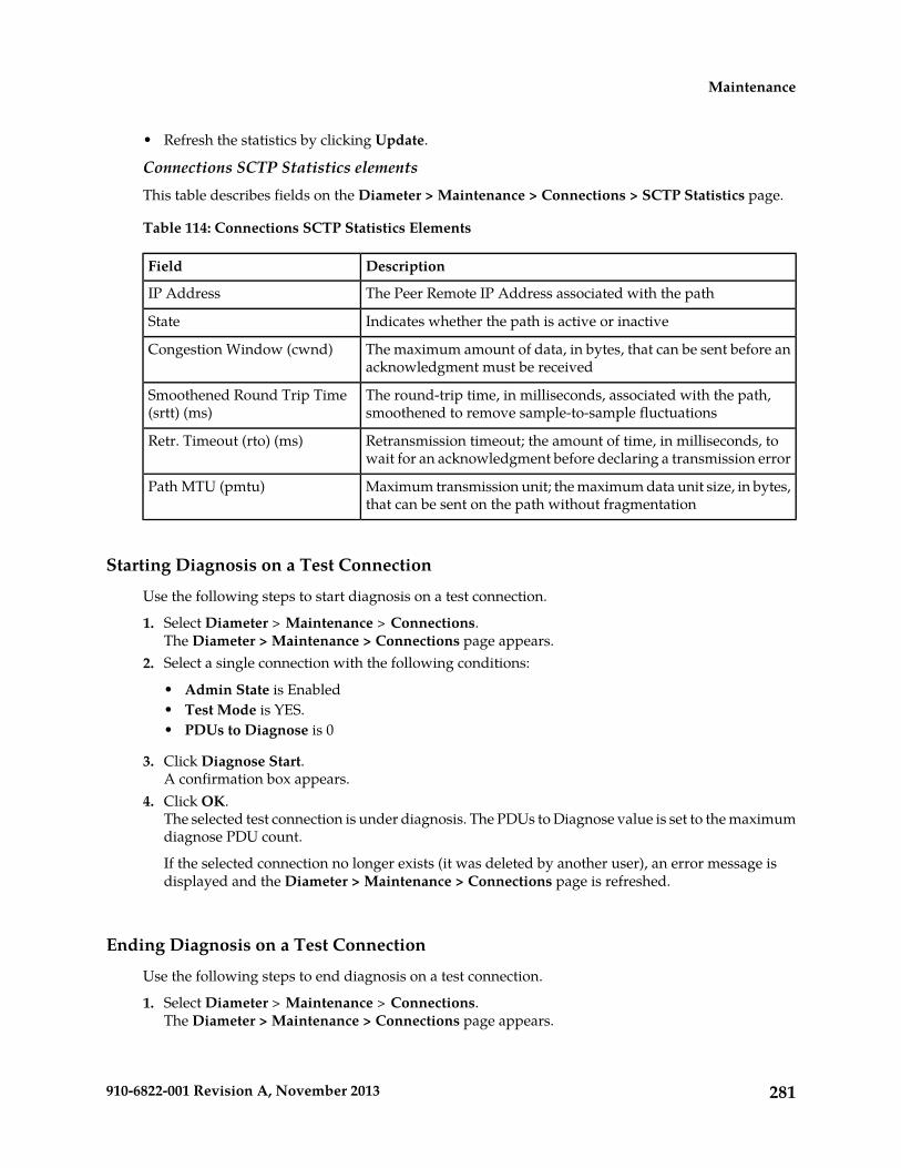
• Refresh the statistics by clicking Update.
Connections SCTP Statistics elementsThis table describes fields on the Diameter > Maintenance > Connections > SCTP Statistics page.
Table 114: Connections SCTP Statistics Elements
DescriptionField
The Peer Remote IP Address associated with the pathIP Address
Indicates whether the path is active or inactiveState
The maximum amount of data, in bytes, that can be sent before anacknowledgment must be received
Congestion Window (cwnd)
The round-trip time, in milliseconds, associated with the path,smoothened to remove sample-to-sample fluctuations
Smoothened Round Trip Time(srtt) (ms)
Retransmission timeout; the amount of time, in milliseconds, towait for an acknowledgment before declaring a transmission error
Retr. Timeout (rto) (ms)
Maximum transmission unit; the maximum data unit size, in bytes,that can be sent on the path without fragmentation
Path MTU (pmtu)
Starting Diagnosis on a Test Connection
Use the following steps to start diagnosis on a test connection.
1. Select Diameter > Maintenance > Connections.The Diameter > Maintenance > Connections page appears.
2. Select a single connection with the following conditions:
• Admin State is Enabled• Test Mode is YES.• PDUs to Diagnose is 0
3. Click Diagnose Start.A confirmation box appears.
4. Click OK.The selected test connection is under diagnosis. The PDUs to Diagnose value is set to the maximumdiagnose PDU count.
If the selected connection no longer exists (it was deleted by another user), an error message isdisplayed and the Diameter > Maintenance > Connections page is refreshed.
Ending Diagnosis on a Test Connection
Use the following steps to end diagnosis on a test connection.
1. Select Diameter > Maintenance > Connections.The Diameter > Maintenance > Connections page appears.
281910-6822-001 Revision A, November 2013
Maintenance
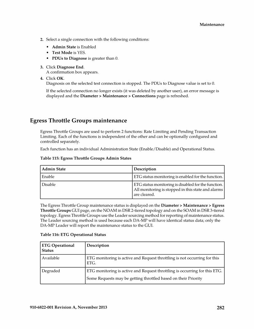
2. Select a single connection with the following conditions:
• Admin State is Enabled• Test Mode is YES.• PDUs to Diagnose is greater than 0.
3. Click Diagnose End.A confirmation box appears.
4. Click OK.Diagnosis on the selected test connection is stopped. The PDUs to Diagnose value is set to 0.
If the selected connection no longer exists (it was deleted by another user), an error message isdisplayed and the Diameter > Maintenance > Connections page is refreshed.
Egress Throttle Groups maintenance
Egress Throttle Groups are used to perform 2 functions: Rate Limiting and Pending TransactionLimiting. Each of the functions is independent of the other and can be optionally configured andcontrolled separately.
Each function has an individual Administration State (Enable/Disable) and Operational Status.
Table 115: Egress Throttle Groups Admin States
DescriptionAdmin State
ETG status monitoring is enabled for the function.Enable
ETG status monitoring is disabled for the function.All monitoring is stopped in this state and alarmsare cleared.
Disable
The Egress Throttle Group maintenance status is displayed on the Diameter > Maintenance > EgressThrottle Groups GUI page, on the NOAM in DSR 2-tiered topology and on the SOAM in DSR 3-tieredtopology. Egress Throttle Groups use the Leader sourcing method for reporting of maintenance status.The Leader sourcing method is used because each DA-MP will have identical status data; only theDA-MP Leader will report the maintenance status to the GUI.
Table 116: ETG Operational Status
DescriptionETG OperationalStatus
ETG monitoring is active and Request throttling is not occurring for thisETG.
Available
ETG monitoring is active and Request throttling is occurring for this ETG.
Some Requests may be getting throttled based on their Priority
Degraded
282910-6822-001 Revision A, November 2013
Maintenance

DescriptionETG OperationalStatus
ETG monitoring is inactive and Request Throttling is not occurring for thisETG. The Operational Reason indicates why this ETG is Inactive.
When Operational Reason is "Disabled" the ETG is Inactive due tomaintenance actions.
Inactive
When the Operational Reason is "SMS Service Degraded" or "No DA-MPLeader" the ETG is Inactive due to a fault condition.
If either Rate Limiting or Pending Transaction Limiting Operational Status is Degraded, then theDiameter Routing Function will throttle the Request messages according to highest severity. Forexample, if Rate Limiting Operational Status is Congestion Level 1 and Pending Transaction LimitingOperational Status is Congestion Level 2 , then the Diameter Routing Function will throttle Requestmessages according to Congestion Level 2 (all Request messages with Priority 0 or 1 will be throttled).
Table 117: ETG Operational Reason
DescriptionETG OperationalReason
ETG is "Disabled" due to maintenance actions.Disabled
No Requests are getting throttled for this ETG for the function.Normal
Request throttling is happening for Requests with Priority 0.Congestion Level 1
Request throttling is happening for Requests with Priority 0 and 1.Congestion Level 2
Request throttling is happening for Requests with Priority 0, 1, and 1.Congestion Level 3
ETG monitoring is Inactive due to "Degraded" status reported to theDiameter Routing Function.
SMS Service Degraded
ETG Monitoring is Inactive due to HA reporting "No DA-MP Leader"condition to the Diameter Routing Function.
No DA-MP Leader
The Diameter > Maintenance > Egress Throttle Groups page provides the Operational Status of theEgress Throttle Groups Rate Limiting and Pending Transactions Limiting functions, including anOperational Reason for the status.
Egress Throttle Groups maintenance fields are described in Egress Throttle Groups maintenance elements
If the column data is not present in the database, the columns for the Egress Throttle Group Name aredisplayed as Unk.
On the Diameter > Maintenance > Egress Throttle Groups page, you can perform the followingactions:
• Filter the list of Egress Throttle Groups to display only the Egress Throttle Groups.• Sort the list by a column, in ascending or descending order, by clicking the column heading. The
default order is by Egress Throttle Groups in ascending ASCII order.• Select one or more (up to 20) Egress Throttle Groups records at a time.• Enable Rate Limiting for up to 20 selected Egress Throttle Groups.
283910-6822-001 Revision A, November 2013
Maintenance

• Disable Rate Limiting for up to 20 selected Egress Throttle Groups.• Enable Pending Transaction Limiting for up to 20 selected Egress Throttle Groups.• Disable Pending Transactions Limiting for up to 20 selected Egress Throttle Groups.• Prevent the page from automatically refreshing every 10 seconds, by clicking the Pause updates
check box.
Egress Throttle Groups maintenance elements
This table describes fields on the Egress Throttle Groups maintenance page.
Table 118: Egress Throttle Groups Maintenance Elements
DescriptionField
Name of the Egress Throttle Group.Egress Throttle Group Name
Rate Limiting Admin State can be Enabled or Disabled.Rate Limiting Admin State
Rate Limiting Operational Status can be:Rate Limiting Operational Status
• Available: at least one Egress Throttle Groups peer or connectionis available.
• Degraded: the Egress Throttle Groups peer or connection is notunavailable but it is not operating as expected. The Rate LimitingOperational Reason field provides additional information onthis status.
• Inactive: all connections for an Egress Throttle Group areunavailable. The Rate Limiting Operational Reason fieldprovides additional information on this status.
• Unk: data is not available in the database.
Rate Limiting Operational Reason as corresponding to the RateLimiting Operational Status:
Rate Limiting OperationalReason
• Available - Normal• Degraded - Congestion Level 1, Congestion Level 2, Congestion
Level 3• Inactive - SMS Service Degraded, No DA-MP Leader, Disabled• Unk - Unk
The cell background color associated with value of PendingTransaction Limiting Operational Reason is as follows:
• Disabled - normal/no special coloring• Normal - normal/no special coloring• SMS Service Degraded - red• No DA-MP Leader - red• Unk - red• Congestion Level 1 - yellow• Congestion Level 2 - yellow• Congestion Level 3 - yellow
284910-6822-001 Revision A, November 2013
Maintenance

DescriptionField
The rate resulting from the application of the Smoothing Factor tothe Egress Request Rate.
Smoothed Rate
Pending Transaction Limiting Admin State can be Enabled orDisabled.
Pending Transaction LimitingAdmin State
Pending Transaction Limiting Operational Status can be:Pending Transaction LimitingOperational Status • Available: at least one Egress Throttle Groups peer or connection
is available.• Degraded: the Egress Throttle Groups peer or connection is not
unavailable but it is not operating as expected. The PendingTransaction Limiting Operational Reason field providesadditional information on this status.
• Inactive: all connections for an Egress Throttle Group areunavailable. The Pending Transaction Limiting OperationalReason field provides additional information on this status.
• Unk: data is not available in the database.
Pending Transaction Limiting Reason as corresponding to thePending Transaction Limiting Operational Status:
Pending Transaction LimitingOperational Reason
• Available - Normal• Degraded - Congestion Level 1, Congestion Level 2, Congestion
Level 3• Inactive - SMS Service Degraded, No DA-MP Leader, Disabled• Unk - Unk
The cell background color associated with value of PendingTransaction Limiting Operational Reason is as follows:
• Disabled - normal/no special coloring• Normal - normal/no special coloring• SMS Service Degraded - red• No DA-MP Leader - red• Unk - red• Congestion Level 1 - yellow• Congestion Level 2 - yellow• Congestion Level 3 - yellow
The combined number of Pending Transactions for the Peers andConnections of an ETG.
Number of PendingTransactions
Displayed as yyyy-month name-date hr:min:sec UTC.Time of Last Update
Viewing Egress Throttle Groups status
Use this task to view the current status of configured Egress Throttle Groups .
Select Diameter > Maintenance > Egress Throttle Groups .The Diameter > Maintenance > Egress Throttle Groups page appears.
285910-6822-001 Revision A, November 2013
Maintenance

Enabling Egress Throttle Groups Rate Limiting
Use the following procedure to Enable Egress Throttle Groups Rate Limiting.
The Egress Throttle Groups Rate Limiting Admin State of Egress Throttle Groups can be updatedirrespective of the Operational Status of the associated Peer Node Connections.
1. Select Diameter > Maintenance > Egress Throttle Groups.The Diameter > Maintenance > Egress Throttle Groups page appears.
2. Select at least 1, but no more than 20 Egress Throttle Groups to Disable.To select multiple Egress Throttle Groups, press and hold the CTRL key when selecting each EgressThrottle Group. To select multiple contiguous Egress Throttle Groups, click the first Egress ThrottleGroup to be selected, then press the SHIFT key and select the last Egress Throttle Group to beselected. All Egress Throttle Groups between are also selected.
3. Click Enable Rate Limiting.a) A confirmation box appears if between 1 and 20 Egress Throttle Group Names are selected.
Click OK in the confirmation box to Enable the selected Egress Throttle Group Names.Click Cancel in the confirmation box to cancel the Enable action. The Admin State of the selectedEgress Throttle Groups remains unchanged.If OK is clicked and any of the following conditions exist, an error message appears:
• Any of the selected Egress Throttle Groups do not exist in the database.• Any of the selected Egress Throttle Groups do not have Egress Throttle Groups Rate Limiting
configured.
b) An Alert Box is displayed if more than 20 Egress Throttle Group Names are selected.
Disabling Egress Throttle Groups Rate Limiting
Use the following steps to Disable Egress Throttle Groups Rate Limiting.
The Egress Throttle Groups Rate Limiting Admin State of Egress Throttle Groups can be updatedirrespective of the Operational Status of the associated Peer Node Connections.
1. Select Diameter > Maintenance > Egress Throttle Groups.The Diameter > Maintenance > Egress Throttle Groups page appears.
2. Select at least 1, but no more than 20 Egress Throttle Groups to Disable.To select multiple Egress Throttle Groups, press and hold the CTRL key when selecting each EgressThrottle Group. To select multiple contiguous Egress Throttle Groups, click the first Egress ThrottleGroup to be selected, then press the SHIFT key and select the last Egress Throttle Group to beselected. All Egress Throttle Groups between are also selected.
3. Click Disable Rate Limiting.a) A confirmation box appears if between 1 and 20 Egress Throttle Groups are selected.
Click OK in the confirmation box to Disable the selected Egress Throttle Groups.Click Cancel in the confirmation box to cancel the Disable action. The Admin State of the selectedEgress Throttle Groups remains unchanged.If OK is clicked and any of the following conditions exist, an error message appears:
• Any of the selected Egress Throttle Groups do not exist in the database.
286910-6822-001 Revision A, November 2013
Maintenance

• Any of the selected Egress Throttle Groups do not have the Egress Throttling Groups RateLimiting configured.
b) An Alert Box is displayed if more than 20 Egress Throttle Groups are selected.
Enabling Egress Throttle Groups Pending Transaction Limiting
Use the following steps to Enable Egress Throttle Groups Pending Transaction Limiting.
The Egress Throttle Groups Pending Transaction Limiting Admin State of Egress Throttle Groups canbe updated irrespective of the Operational Status of the associated Peer Node Connections.
1. Select Diameter > Maintenance > Egress Throttle Groups.The Diameter > Maintenance > Egress Throttle Groups page appears.
2. Select at least 1, but no more than 20 Egress Throttle Groups to Disable.To select multiple Egress Throttle Groups, press and hold the CTRL key when selecting each EgressThrottle Group. To select multiple contiguous Egress Throttle Groups, click the first Egress ThrottleGroup to be selected, then press the SHIFT key and select the last Egress Throttle Group to beselected. All Egress Throttle Groups between are also selected.
3. Click Enable Pending Transaction Limiting.a) A confirmation box appears if between 1 and 20 Egress Throttle Group Names are selected.
Click OK in the confirmation box to Enable the selected Egress Throttle Group Names.Click Cancel in the confirmation box to cancel the Enable action. The Admin State of the selectedEgress Throttle Groups remains unchanged.If OK is clicked and any of the following conditions exist, an error message appears:
• Any of the selected Egress Throttle Groups do not exist in the database.• Any of the selected Egress Throttle Groups do not have Egress Throttling Groups Pending
Transaction Limiting configured.
b) An Alert Box is displayed if more than 20 Egress Throttle Groups are selected.
Disabling Egress Throttle Groups Pending Transaction Limiting
Use the following steps to Disable Egress Throttle Groups Pending Transaction Limiting.
The Egress Throttle Groups Pending Transaction Limiting Admin State of Egress Throttle Groups canbe updated irrespective of the Operational Status of the associated Peer Node Connections.
1. Select Diameter > Maintenance > Egress Throttle Groups.The Diameter > Maintenance > Egress Throttle Groups page appears.
2. Select at least 1, but no more than 20 Egress Throttle Groups to Disable.To select multiple Egress Throttle Groups, press and hold the CTRL key when selecting each EgressThrottle Group. To select multiple contiguous Egress Throttle Groups, click the first Egress ThrottleGroup to be selected, then press the SHIFT key and select the last Egress Throttle Group to beselected. All Egress Throttle Groups between are also selected.
3. Click Disable Pending Transaction Limiting.a) A confirmation box appears if between 1 and 20 Egress Throttle Groups are selected.
Click OK in the confirmation box to Disable the selected Egress Throttle Groups.
287910-6822-001 Revision A, November 2013
Maintenance

Click Cancel in the confirmation box to cancel the Disable action. The Admin State of the selectedEgress Throttle Groups remains unchanged.If OK is clicked and any of the following conditions exist, an error message appears:
• Any of the selected Egress Throttle Groups do not exist in the database.• Any of the selected Egress Throttle Groups do not have the Egress Throttling Pending
Transaction Limiting configured.
b) An Alert Box is displayed if more than 20 Egress Throttle Groups are selected.
Application maintenance
The Diameter > Maintenance > Applications page allows you to view state and congestion informationabout existing DSR applications.
On the Diameter > Maintenance > Applications page, you can perform the following actions:
• Filter the list of Applications to display only the desired Applications.• Sort the list by column, in ascending or descending order, by clicking the column heading. The
default order is by DSR Application Name in ascending ASCII order.
• Change the Admin State of a selected DSR Application to Enabled or Disabled on a selected MPServer. See Enabling Applications and Disabling Applications.
• Prevent the page from automatically refreshing by clicking the Pause updates check box.
Applications maintenance elements
The following table describes fields on the Applications maintenance page.
Table 119: Applications Maintenance Elements
DescriptionField
Name of the DSR ApplicationDSR Application Name
Hostname of the Message Processor Server from which status is reportedMP Server Hostname
Admin State of the DSR Application (Enabled, Disabled). The Admin Statepersists over DSR Application restart and server reboot.
Admin State
Operational Status of the DSR Application (Unavailable, Available, orDegraded)
Operational Status
Operational Reason that is filled in by the DSR Application and extractedfrom the database
Operational Reason
Congestion Level of the DSR Application (Normal, CL1, CL2, CL3)Congestion Level
Time stamp that shows when the application changed to the status shownin Operational State
Time of Last Update
288910-6822-001 Revision A, November 2013
Maintenance

DescriptionField
If the run-time data for Operational Status, Operational Reason, Congestion Level, and Time of LastStatus change is not present in the database, the data is displayed as Unknown.
Viewing Application status
Use this task to view the current status of configured applications.
Select Diameter > Maintenance > Applications.The Diameter > Maintenance > Applications page appears.
Enabling Applications
Use this task to enable one or more applications.
Applications are enabled only on the MP servers shown in the rows you select.
1. Select Diameter > Maintenance > Applications.The Diameter > Maintenance > Applications page appears.
2. Select one or more applications to enable.To select multiple applications, press the CTRL key when selecting each application. To selectmultiple contiguous applications, click the first application you want, then press the SHIFT keyand select the last application you want. All the applications between are also selected.
3. Click Enable.A popup window appears.
4. Click
• OK to enable the selected applications and bring the applications to the Available OperationalState.
• Cancel to return to the Diameter > Maintenance > Applications page without enabling theapplications.
If OK is clicked and an application no longer exists in the system (it was deleted by another user),an error message is displayed and the Diameter > Maintenance > Applications page is refreshed.
Disabling Applications
Use this task to disable one or more applications.
Applications are disabled only on the MP servers shown in the rows you select.
1. Select Diameter > Maintenance > Applications.The Diameter > Maintenance > Applications page appears.
2. Select one or more applications to disable.To select multiple applications, press the CTRL key when selecting each application. To selectmultiple contiguous applications, click the first application you want, then press the SHIFT keyand select the last application you want. All the applications between are also selected.
3. Click Disable.
289910-6822-001 Revision A, November 2013
Maintenance

A confirmation box appears.4. Click
• OK to disable the selected applications and bring the applications to the Unavailable OperationalState.
• Cancel to return to the Diameter > Maintenance > Applications page without disabling theapplications.
If OK is clicked and an application no longer exists in the system (it was deleted by another user),an error message is displayed and the Diameter > Maintenance > Applications page is refreshed.
DA-MP maintenance
The Diameter > Maintenance > DA-MPs page allows you to view state and congestion informationabout Diameter Agent Message Processors.
On the Diameter > Maintenance > DA-MPs page, you can perform the following actions:
• Click the Peer DA-MP Status tab to view peer status information for the DA-MPs.• Click the DA-MP Connectivity tab to view information about connections on the DA-MPs.• Click the tab for an individual DA-MP to see DA-MP and connection status from the point-of-view
of that DA-MP.
If there are more tabs than fit on one page, click the left and right arrow buttons to scroll throughthe tabs, or click the down arrow button to select a specific tab from a menu.
• Prevent the page from automatically refreshing by clicking the Pause updates check box.
For detailed information about the fields displayed on the Diameter > Maintenance > DA-MPs page,see DA-MPs maintenance elements.
DA-MPs maintenance elements
The following table describes fields on the DA-MPs maintenance page.
Table 120: DA-MPs Maintenance Elements
DescriptionField
Peer DA-MP Status Tab
The numeric identifier of the reporting DA-MP ServerMP ID
The hostname of the reporting DA-MP ServerMP Server Hostname
The number of peer DA-MPs whose status is available# Peer MPs Available
The number of peer DA-MPs whose status is degraded# Peer MPs Degraded
The number of peer DA-MPs whose status is unavailable# Peer MPs Unavailable
Indicates whether a DA-MP reports itself as MP Leader. The MP Leaderprovides status information to the OAM for Route Lists, Route Groups,
MP Leader
290910-6822-001 Revision A, November 2013
Maintenance
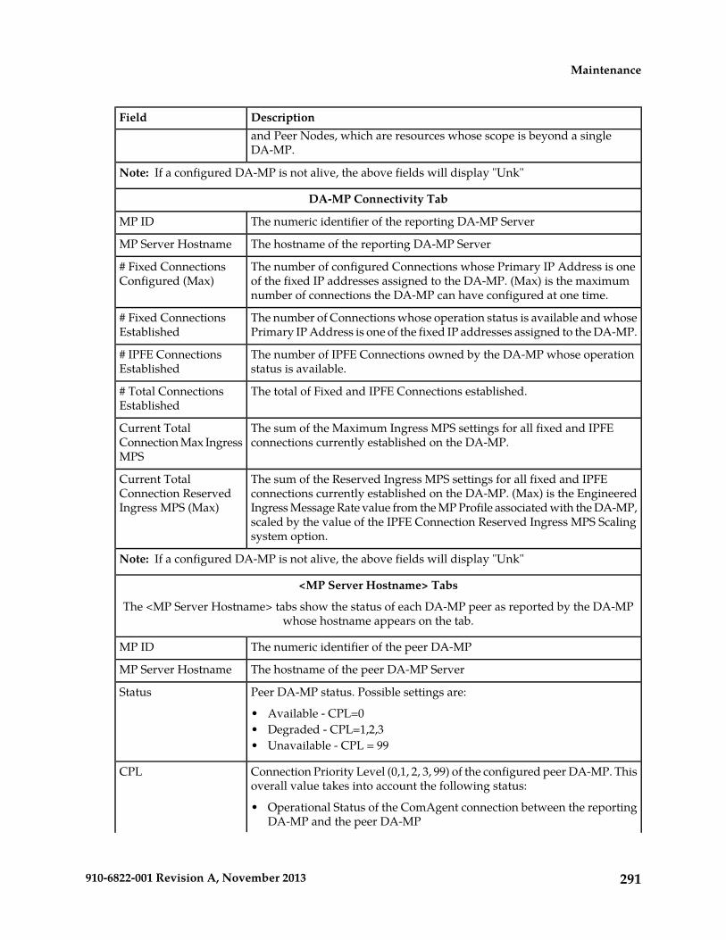
DescriptionFieldand Peer Nodes, which are resources whose scope is beyond a singleDA-MP.
Note: If a configured DA-MP is not alive, the above fields will display "Unk"
DA-MP Connectivity Tab
The numeric identifier of the reporting DA-MP ServerMP ID
The hostname of the reporting DA-MP ServerMP Server Hostname
The number of configured Connections whose Primary IP Address is oneof the fixed IP addresses assigned to the DA-MP. (Max) is the maximumnumber of connections the DA-MP can have configured at one time.
# Fixed ConnectionsConfigured (Max)
The number of Connections whose operation status is available and whosePrimary IP Address is one of the fixed IP addresses assigned to the DA-MP.
# Fixed ConnectionsEstablished
The number of IPFE Connections owned by the DA-MP whose operationstatus is available.
# IPFE ConnectionsEstablished
The total of Fixed and IPFE Connections established.# Total ConnectionsEstablished
The sum of the Maximum Ingress MPS settings for all fixed and IPFEconnections currently established on the DA-MP.
Current TotalConnection Max IngressMPS
The sum of the Reserved Ingress MPS settings for all fixed and IPFEconnections currently established on the DA-MP. (Max) is the Engineered
Current TotalConnection ReservedIngress MPS (Max) Ingress Message Rate value from the MP Profile associated with the DA-MP,
scaled by the value of the IPFE Connection Reserved Ingress MPS Scalingsystem option.
Note: If a configured DA-MP is not alive, the above fields will display "Unk"
<MP Server Hostname> Tabs
The <MP Server Hostname> tabs show the status of each DA-MP peer as reported by the DA-MPwhose hostname appears on the tab.
The numeric identifier of the peer DA-MPMP ID
The hostname of the peer DA-MP ServerMP Server Hostname
Peer DA-MP status. Possible settings are:Status
• Available - CPL=0• Degraded - CPL=1,2,3• Unavailable - CPL = 99
Connection Priority Level (0,1, 2, 3, 99) of the configured peer DA-MP. Thisoverall value takes into account the following status:
CPL
• Operational Status of the ComAgent connection between the reportingDA-MP and the peer DA-MP
291910-6822-001 Revision A, November 2013
Maintenance

DescriptionField• Congestion level of the peer DA-MP• Status of the DSR Process running on the peer DA-MP
Reason for CPL setting. Possible settings are:CPL Reason
• Available - There is no MP-level impairment on the peer DA-MP• MP Congestion - Indicates peer DA-MP is in congestion (CL1, CL2, or
CL3)• Inter-MP Connection Unavailable - The ComAgent connection between
the reporting DA-MP and the peer DA-MP has an Operation Status ofUnavailable.
• DSR Process Not Running - The DSR process is not running on the peerDA-MP.
Viewing DA-MP status
Use this task to view the current status of configured Diameter Agent Message Processors.
Select Diameter > Maintenance > DA-MPs.The Diameter > Maintenance > DA-MPs page appears.
292910-6822-001 Revision A, November 2013
Maintenance

Chapter
5Reports
The Diameter Reports GUI pages provide access tothe following reports:
Topics:
• Overview.....294• Diagnostics Tool reports• Generating Diagnostics Tool Reports.....294• MP Statistics (SCTP) reports• Updating and Viewing MP Statistics (SCTP)
Reports.....296
293910-6822-001 Revision A, November 2013

Overview
The Diameter Reports GUI pages provide access to the following reports:
• Diagnostics Tool reports
The DSR Diagnostics Tool provides the capability to test Mediation Rule Templates that are in"Test" or "Active" state before they are subjected to live traffic in the network. A test message isinjected into the system on a connection that is in Test Mode (see Connection maintenance). At varioustracepoints, the DSR Diagnostics Tool logs the Rules that are applied, actions taken, and otherdiagnostic information on a test message that is injected into the system. The Diagnostics ToolReports can be used to view the logged information for each test.
• MP Statistics (SCTP) reports
The MP Statistics (SCTP) Reports page displays the Message Processor (MP) SCTP statistics perMP, for all MPs or for a selected set of MPs. Each row shows the statistics for one MP.
Generating Diagnostics Tool Reports
The DSR Diagnostics Tool provides the capability to test Mediation Rule Templates that are in "Test"or "Active" state before they are subjected to live traffic in the network.
The Rule Templates are tested for a message that is injected into a connection that is set to Test Mode.A connection can be set to Test Mode only when it is created; an existing non-test connection cannotbe changed into a test connection. A maximum of two test connections can exist in the system at onetime.
All incoming messages on a test connection are marked as TestMode messages. When the DiagnoseStart button is clicked on the Diameter > Maintenance > Connections page, TestMode messages aresent on a test connection that is selected, in Test Mode, and not Disabled.
At various trace points, the DSR Diagnostics Tool logs the Rules that are applied, actions taken, andother diagnostic information on a test message that is injected into the system. Reports are providedthat are based on the logs. Logging begins when the Diagnose Start button is clicked. The test can bestopped by clicking the Diagnose Stop button on the Maintenance Connection page.
Use this task to generate Diagnostics Tool reports from the test logs.
1. Select Diameter > Reports > Diagnostics Tool.The Diameter > Reports > Diagnostics Tool page appears.
2. Select zero records, or select one or more connection records under one or more connection namesin the Connection list.
• If zero records are selected, the report will include all available Diagnostics Tool data.• If one or more records are selected, the report will include data for the selected test runs.
3. Click the Report button.The Diameter > Reports > Diagnostics Tool [Report] page appears and displays the generatedreport. You can save and print the report.
294910-6822-001 Revision A, November 2013
Reports

Viewing, Printing, and Saving Diagnostics Tool Reports
Use this task to view, print, and save reports that are generated from Diagnostics Tool test logs.
When the Report button is clicked on the Diameter > Reports > Diagnostics Tool page, a report isgenerated for all available or the selected test records.
The report has two parts:
• Title Block
The Title Block contains the following information:
• <Application Name> Diagnostics Tool Report• Report Generated: <time and date in UTC>• From: <active/standby><server Role> on host <Hostname>• Report Version: <application version>• User: userid of the GUI user who generated the report>
• Section Block
One or more Section Blocks follow the Title Block. Each Section Block corresponds to one test runon one connection.
Each section in a Section Block corresponds to reports for a test run. A section displays the followingheader information:
• Report for <connection name>• Test run begun: <timestamp when the test run was started>
Each message that was diagnosed in a test run is identified by a PDU ID. The log entriescorresponding to the message are reported in ascending order of the timestamp.
Each subsection has the following line as a header: PDU ID <pduId>. The heading is followedby the zero or more lines of log entries corresponding to the PDU, in the following format:<timestamp> <tracepoint name> : <log text>.
For example:
Report for Connection1Test Run begun: Tue May 24 19:51:39 2011 UTC- - - - - - - - - - - - - - - - - - - - - - - - - - - - - - - - - - - - - - - -
PDU ID 42011-May-16 10:46:10 UTC Tracepoint0 :Message Received2011-May-16 10:49:51 UTC Tracepoint1 :Message Sent to DRL................................................................................
PDU ID 52011-May-18 04:18:25 UTC Tracepoint0 : Message Received................................................................................
1. To print the report, click the Print button.A dialog box opens, allowing you to choose the printer to be used for printing the report.
2. To save the report, click the Save button.
295910-6822-001 Revision A, November 2013
Reports

A dialog box opens, allowing you to choose the location in which to save the report.
Updating and Viewing MP Statistics (SCTP) Reports
The Diameter > Reports > MP Statistics (SCTP) page displays the Message Processor (MP) SCTPstatistics per MP, for all MPs or for a selected set of MPs. Each row shows the statistics for one MP.
The statistics are updated on the page each time the Update button is clicked. The counts are notrefreshed automatically.
The MP Statistics (SCTP) Report is described in MP Statistics (SCTP) report elements.
Use this task to update and view MP Statistics (SCTP) reports.
1. Select Diameter > Reports > MP Statistics (SCTP).The Diameter > Reports > MP Statistics (SCTP) page appears.
2. Select the Scope of the report from the Scope pulldown list.
• To be able to select individual MPs, choose Server.• To select all MPs in a Network Element, choose NE.
3. In the box on the right, list the MPs to be included in the report.
• To add a specific MP to the list on the right, so that its statistics will be shown in the report,select the MP in the box on the left, and click Add.
Repeat this action for each specific MP that is to be listed in the report.
• To add all of the available MPs to the list on the right, click the AddAll button.
• To remove a specific MP from the report, select the MP in the box on the right, and click Remove.The selected MP moves to the box on the left.
• To remove all of the listed MPs from the box on the right (to prepare to create a new list), clickRemoveAll. All of the MPs from the box on the right move to the box on the left.
4. When the list in the box on the right contains the MPs for the report, click Go.The selected MPs and their statistics are listed in the columns of the report.
5. Click Update to display the current statistics for the listed MPs.
MP Statistics (SCTP) report elements
Table 121: MP Statistics (SCTP) Report Elements describes the fields for selecting MPs and the contentsof the columns on the Diameter > Reports > MP Statistics (SCTP) page.
Table 121: MP Statistics (SCTP) Report Elements
Data Input NotesDescriptionField
MP Selection
296910-6822-001 Revision A, November 2013
Reports

Data Input NotesDescriptionField
Format: pulldown listSelect Network Element or Server. All of theselected MPs have the same Scope.
Scope
Range: NE, Server
Format: List of allMPs/NEs; list ofselected MPs/NEs
Left list is all available MPs or NEs, dependingon the selected Scope.
Right box is all MPs or NEs selected for the report.
Statistics for
Report Columns
DescriptionField
Hostname of the MP Server from which status is reportedMP
Current number of SCTP associations establishedCurrent Established
Number of locally-initiated SCTP associations establishedEstablished (LocalInitiated)
Number of peer-initiated SCTP associations establishedEstablished (PeerInitiated)
Number of IP packets received. Each IP packet contains one or more SCTPchunks.
Packets Rcvd
Number of IP packets sent. Each IP packet contains one or more SCTPchunks.
Packets Sent
Number of SCTP DATA Chunks received not including duplicatesDATA chunks Rcvd(excluding Duplicates)
Number of SCTP DATA Chunks sent not including duplicatesDATA chunk Sent(excluding Duplicates)
Number of SCTP DATA Chunks retransmitted due to fast transmit ruleFast Retransmits
Number of SCTP DATA Chunks retransmitted due to acknowledgmenttimeout
Retransmits
Number of SCTP Control Chunks sent. A control chunk is one of: INIT,INIT ACK, COOKIE ECHO, COOKIE ACK, SACK
CTRL chunk Sent
Number of SCTP Control Chunks received. A control chunk is one of: INIT,INIT ACK, COOKIE ECHO, COOKIE ACK, SACK
CTRL chunks Rcvd
Number of SCTP User messages fragmented because message lengthexceeds path MTU
Fragmented UserMessages
Number of SCTP User messages reassembled due to fragmentationReassembled UserMessages
Number of ABORT messages receivedAborted
Number of SHUTDOWN messages receivedShutdown
Number of Out of the Blue messages received from an unknown peerOut of Blue ChunksRcvd
297910-6822-001 Revision A, November 2013
Reports

Data Input NotesDescriptionField
Number of SCTP Checksum Errors detectedChecksum Error
298910-6822-001 Revision A, November 2013
Reports

Chapter
6Diameter Mediation
The Diameter Mediation feature allows easy creationof Mediation Rules.
Topics:
• Mediation overview.....300• Rule Templates.....302• Formatting Value Wizard.....328• Enumerations.....336• Triggers.....340• State and Properties.....344• Base Dictionary.....348• Custom Dictionary.....350• All-AVP Dictionary.....355• Vendors.....357• Rule Sets.....360
299910-6822-001 Revision A, November 2013

Mediation overview
Diameter message mediation helps to solve interoperability issues by using rules to manipulate headerparts and Attribute-Value Pairs (AVPs) in an incoming routable message, when data in the messagematches some specified conditions at a specified point of message processing. Tasks of the “if conditionmatches, then do some action” type can be solved in the most efficient way.
The Diameter Mediation feature extends the CAPM (Computer-Aided Policy Making) framework toallow for easy creation of Mediation rules for use in 3G, LTE and IMS networks. Mediation RuleTemplates are created to define the Conditions that must be matched in a message and the Actionsthat are applied to modify the message contents.
• A Condition defines a part of the message that is used in the comparison, an operator for the typeof comparison, and a type of data that must match the data in the message part. Two or moreConditions in the same Rule Template are collectively referred to as a Condition Set; the Conditionsare “AND”ed in the comparison process.
• An Action can be adding, altering, or deleting AVPs; modifying the message header Flags, Length,Command-Code, or Application-ID; or other operations. Two or more Actions in a Rule Templateare collectively referred to as an Action Set.
A Message Copy Action can also be defined to trigger Diameter Message Copy for copying amessage to a DAS.
Mediation can be performed on:
• Routable Diameter messages only (Mediation is not supported on Diameter CEA and CER, DWRand DWA, and DPR and DPA messages)
• Specific Diameter interfaces or all Diameter interfaces (“interfaces” refers to Diameter ApplicationIds and not hardware/network interfaces)
Mediation Message Copy can be performed only for Request messages, and is ignored if set at MediationTrigger Point ATP1.
After a Rule Template definition is complete, a Rule Set can be generated from the Rule Template.The data needed for the Conditions and the Actions is provisioned in the generated Rule Set. AMediation rule is an instance of the data needed for the execution of Mediation logic. The actual dataneeded for the Conditions and the Actions is provisioned in one or more rules in the generated RuleSet. All of the rules associated with one Mediation Rule Template are collectively referred to as theRule Set for the Rule Template. See Rule Sets.
Rule Sets can be associated with pre-defined Request or Answer Trigger points in the DSR messageprocessing logic. When message processing reaches a Trigger point and the Conditions in an associatedRule Set are met, the Actions for that Rule Set are applied to the message. The changes to the messagecontent can result in modifying the message processing behavior at that Trigger point in the processinglogic. See Triggers
Diameter Mediation provides a Rule Templates interface, a Rule Sets interface, and other GUI screens:
• The Rule Templates interface is used primarily for the creation and modification of Rule Templates.
When the Mediation feature is activated in the system and “Meta-Administrator” privileges areactivated for the feature, the Rule Templates folder appears under the Mediation folder in theDiameter left-hand GUI menu.
300910-6822-001 Revision A, November 2013
Diameter Mediation

The “Meta-Administrator” privileges can be deactivated later, so that the Rule Templates folderdoes not appear under the Mediation folder. This can be to prevent unauthorized modification ofthe created Rule Templates in the system.
A user, who could be designated as the “Meta-Administrator”, can use the Rule Templates GUIscreens and other Mediation GUI screens to perform the following tasks:
• Add, edit, and delete Enumeration Types, AVP Dictionary entries, and Vendors that are usedin creating Rule Templates (see Enumerations, Custom Dictionary, and Vendors)
• Create, modify, delete, copy, import, and export Rule Templates (see Rule Templates)• Add help text to a Rule Template; the help text will be available for the Rule Set that is generated
from the Rule Template (see Rule Templates)• Associate Rule Sets with Triggers, and remove Rule Set associations with Triggers (see Triggers)• Set the Action Error Handling property of a Rule Set (see State and Properties)• Change the state of a Rule Template (see State and Properties)
When a Rule Template is being created or modified, it is in the Development state.
The Rule Template state can be changed from Development to Test to allow its Rule Set to betested or to allow the Rule Template to be exported.
The Rule Template state can be changed to Active to enable use of its generated Rule Set forlive traffic.
The Rule Template state can be changed from Test or Active back to Development to allowmodification of the Rule Template (all existing rule provisioning for its associated Rule Sets willbe deleted).
• The Rule Sets interface is used primarily for the provisioning of rules and actual data in Rule Sets.
After a Rule Template has been created, the generation of the Rule Set from the Rule Templatecreates an entry in the Mediation Rule Sets GUI folder.
A user, who could be designated as the “Rule Set Administrator”, can use the Rule Sets entries,Enumerations, Triggers, and State & Properties GUI screens, and other GUI screens to perform thefollowing tasks, but cannot create, modify, copy, or export Rule Templates:
• Add a rule to a Rule Set, and provision the actual data that is used by the rule in the messagematching process (see Rule Sets)
• Edit and delete rules in Rule Sets (see Rule Sets)• Delete Rule Sets (see Rule Sets)• Change the state of a Rule Template (see State and Properties)
The Rule Template state can be changed to Test for testing its Rule Sets or to Active for enablingits Rule Sets for use with live traffic.
When “Meta-Administrator” privileges are deactivated, the state cannot be changed back toDevelopment.
• Set the Action Error Handling property of a Rule Set (State and Properties• Test a Rule Set
A Diagnostics Tool is available to test Mediation rules before they are subjected to live trafficin the network. The DSR Diagnostics Tool logs the rules applied, Actions taken, and otherdiagnostics information when a test message is injected into the system. The tool generatestraffic and sends Diameter Messages on a test connection. As a test message traverses the system,
301910-6822-001 Revision A, November 2013
Diameter Mediation

the DSR application logic generates diagnostics messages at Trigger points. The Diameter >Reports > Diagnostics Tool GUI is used to view the diagnostics log reports. See Reports.
• Associate Rule Sets with Triggers, and remove Rule Set associations with Triggers (see Triggers)• Import previously exported Rule Templates (see State and Properties)
The state of an imported Rule Template is set to Test by default.
• View the Enumeration types that can be used in the rules (see Enumerations)• View the Vendors that can be used in Rule Templates (see Vendors)
Mediation-Triggered Diameter Message Copy
The Rule Template "Message Copy" Action can be defined to trigger Diameter Message Copy formessages that are processed by Diameter Mediation.
The Message Copy Action triggers Diameter Message Copy, and specifies the Message CopyConfiguration Set (MCCS) that contains the Request/Answer content criteria to be used by the MessageCopy function to copy the message to a DAS. The Message Copy Configuration Set specifies a RouteList for the DAS. See Message Copy Configuration Set configuration.
The Message Copy Action is ignored if set at ATP10 (Diameter Answer message prior to be forwardedto connection).
If Message Copy is triggered for the same message from multiple locations, the Message CopyConfiguration Set for the latest Message Copy triggering prevails.
In the case of Request re-route due to invalid Result-Code, only the Message Copy Configuration Setthat is associated with the Answer that completes the transaction at ATP1 is considered.
The Message Copy is performed after the completion of the original transaction. The copy of themessage is not processed by the Mediation Triggering Points.
Rule Templates
Rule Templates are created by:
• Formulating the Conditions against which to match incoming requests or responses• Defining the Mediation Actions that are applied to the message when the Conditions match
Note: The "Meta-Administrator" privileges must be activated for the Diameter Mediation featurebefore the Rule Templates GUI screens can be accessed to create and modify Rule Templates.
A Rule Template is created by configuring Settings, Conditions, and Actions.
Settings
Settings are the main Rule Template properties:
• Rule Template Name: A placeholder for meaningful text to describe the purpose of the RuleTemplate and Rule Set.
• Message type support: The type of message processing that is supported by a Rule Template;either a Request, an Answer, or both. In Diameter Mediation, both Request and Answer aresupported, and the element value cannot be changed.
302910-6822-001 Revision A, November 2013
Diameter Mediation

Conditions
One or more (up to 5) matching expressions (Conditions) can be defined in a Rule Template. Theexpressions are combined into one logical expression with "AND" operators, so that the request orresponse matches the condition set if all of the expressions are true. If no matching expression isdefined, the message unconditionally matches.
Each matching expression consists of a left-hand value or operand, an operator, and a right-hand valueor operand.
• Left value: Allows accessing any part of a message, any information stored by the previous RuleTemplate, and any information that the application resolves runtime.
• Operator: Allows comparison of the Left value and the Right value• Right value: Allows performing the syntax check for the entered data on the generated Rule Sets
page.
Conditions can be configured to cause Mediation to use fast database lookups of the rule data. SeeFast Search.
Actions
Actions indicate what to do when the conditions match (such as modify the part of a message, forwarda message, send a reply, insert or remove headers, or set attributes for further processing). Actionsimplement the mediation of a message.
When the message processing reaches a selected triggering point, the Conditions of the Rule Templateare examined for the message. If the Conditions match, Mediation Actions are applied to the message.The Actions allow manipulation of some particular part of the message, adding or deleting informationin the message, forwarding the message to a specific destination, or triggering of Diameter MessageCopy to send a copy of the message to a DAS.
The Actions to take when a Mediation operation is triggered and its Condition Set is matched aredefined in the Rule Template. Actions belonging to the same Rule Template form an Action Set. SeeRule Template elements for the Actions available in Rule Templates.
On the Diameter > Mediation > Rule Templates page, you can perform the following actions:
• Filter the list of Rule Template Names to display only the desired Rule Templates.
• Click the Insert button.
The Diameter Mediation Rule Templates [Insert] page opens. You can add a new Rule Templatesand its values. See Adding a Rule Template. If the maximum number of Rule Templates (100) alreadyexist in the system, the Rule Templates [Insert] page will not open, and an error message isdisplayed.
• Click the Import button.
The Diameter > Mediation > Rule Templates [Import] page opens. You can import a Rule Templatefrom a location outside the Diameter system, to which the Rule Template was previously exportedfrom Mediation. See Importing a Rule Template. If the maximum number of Rule Templates (100)already exist in the system, the Rule Templates [Import] page will not open, and an error messageis displayed.
• Select a Rule Template Name in the list, and click the Copy button.
The Diameter > Mediation > Rule Templates [Copy] page opens. You can change the informationfor the copied Rule Template to create a new Rule Template. See Copying a Rule Template. If the
303910-6822-001 Revision A, November 2013
Diameter Mediation
maximum number of Rule Templates (100) already exist in the system, the Rule Templates [Copy]page will not open, and an error message is displayed.
• Select a Rule Template Name in the list, and click the Edit button.
The Diameter > Mediation > Rule Templates [Edit] page opens. You can edit the selected RuleTemplate. See Changing a Rule Template.
• Select a Rule Template Name in the list, and click the Delete button to remove the selected RuleTemplate. See Deleting a Rule Template.
• Select a Rule Template Name in the list, and click the Export button.
The Diameter > Mediation > Rule Templates [Export] page opens. You can export the selectedRule Template to a location outside of the Diameter system. See Exporting a Rule Template.
• Select a Rule Template Name in the list, and click the Set Help button.
The Diameter > Mediation > Rule Templates [Set Help] page opens. You can create online helpfor the selected Rule Template. See Adding online help to a Rule Template.
Fast Search
The Fast Search option is used to cause Mediation to use fast database lookups. If Fast Search is notused, the values of each condition are checked one-by-one until the first match is found.
The Fast Search option appears as the first element for each condition that is defined in the Conditionssection for a Rule Template. The Fast Search option is not editable; it serves only to indicate whetherFast Search will or will not be used for the condition:
All of the conditions with the Fast Search option enabled must precede any conditions without FastSearch enabled in the Rule Set list. If any conditions without Fast Search enabled precede conditionswith Fast Search enabled, a database lookup could fall back to slow search because of the order of theconditions.
The value of the Fast Search option is determined by the Operator and the Right value that are selectedfor the condition. The Fast Search value is either the “Yes” (check mark) sign or the “No”(red circlewith a red line through it) sign.
• Fast Search is supported only by the “equals”, “begins with (longest match)”, “begins with”, “iswithin”, “exists”, “does not exist”, “is true”, “is false” Operators.
• If a “no” sign is displayed for the Fast Search option, then the Operator “=^^” (begins with – longestmatch) is disabled (cannot be selected) in the Operator drop down list for the condition.
• Regardless of the Operator, the Fast Search option is supported if the Right value is a Fixed value(a data value was entered in the Rule Template, and the value cannot be changed in the Rule Set).
• Regardless of the Operator, the Fast Search option is not supported if the “xl-value” Right valuetype is selected without a Fixed value.
The “Yes” sign is displayed for the Fast Search option if:
• One of the Operators “==” (equals), “=^^” (begins with-longest match), “=^ (begins with)”, “iswithin”, “exists”, “does not exist”, “is true, “is false” is selected and the Right value type is not“xl-value”.
• The Default value is Fixed regardless of the selected Operator and Right value type; and eitherthe condition is the first one in the Condition Set, or all the conditions above it also have a “Yes”sign for the Fast Search option.
304910-6822-001 Revision A, November 2013
Diameter Mediation

In any other case, the “No” sign is displayed.
When the selected Operator, the order of the conditions, or the Right value type changes, then everyFast Search “Yes” and “No” value has to be reevaluated and redrawn, and the Case-sensitive checkbox is either enabled or disabled accordingly.
If a “Yes” sign has to be changed to “No” under the Fast Search heading as a result of the reevaluation,and the related Operator “=^^” (begins with-longest match) was selected, a dialog box is displayedto confirm disabling of Fast Search:
Case-sensitive lookup depends on the Fast Search option; the check box is unchecked and disabled ifFast Search is also disabled. The Case-sensitive check box is enabled only for the Octet-String andUTF8String Right value types.
Rule Template elements
Table 122: Rule Template elements describes the information that can be contained in a Rule Template.Some of these elements appear only when adding, editing, or copying a Rule Template.
Table 122: Rule Template elements
Data Input NotesDescriptionElement
Settings: This section contains basic information for the Rule Template.
Format: a-z, A-Z, 0-9, -, ., @, and _("Unset" cannot be used as a RuleTemplate Name.)
Name used to label this Rule Template inthis application.
This field is required.
Rule TemplateName
Range: 1-255 characters
Format: Check marksIndicates the type of message processingthat is supported by the Rule Template
Message SupportType Range: Request, Answer, or both are
checked.(Request, Answer, or both). The MessageSupport Type depends on the selectedconditions and actions. Default: Both are checked
This field cannot be edited.
Conditions: This section defines a set of zero to five matching expressions.
The defined matching expressions are combined to make one logical expression with AND operators,so the set matches on the message if all the expressions are true.
If no matching expression is defined, the message unconditionally matches.
OR operators can be simulated by setting up multiple Rule Templates.
All conditions are supported by both requests and replies.
Format: Check mark (Yes) or redcircle with red line through it (No);not editable
If check marked, fast database lookupsare used. Otherwise, the values of thespecified field are checked one-by-one
Fast Search
until the first match is found. See FastSearch. Range: Yes sign or No sign
Default: Yes sign
305910-6822-001 Revision A, November 2013
Diameter Mediation

Data Input NotesDescriptionElementThe value of the Fast Search option isdetermined by:
All Conditions with the Fast Searchoption checked must precede theothers to maintain the Fast Search.• The selected Operator, the Right value
type, and the Default value When the Default value is Fixed,Fast Search is enabled regardless of• Yes (check mark) if one of the
following Operators is selected and the selected Operator and Rightvalue type.the Right value type is not
"xl-value":
• equals (==)• begins with-longest match
(=^^)• begins with (=^)• is within• exists• does not exist• is true• is false
• The Condition evaluation order;Conditions are ANDed as follows:
• Yes (check mark) if the Conditionis the first one in the Conditionssection or all Conditions above thisone also have a Yes check mark forthe Fast Search option.
• No sign for other cases.
Fast Search is not automatically disabledwhen "any" instance of an AVP is lookedup in the condition. Fast Search must bemanually disabled for the selectedinstance number of "any". Disabling theFast Search can be achieved, for example,by selecting an "xl-value" as the Rightvalue.
Format: Text string
Range: 1 to 64 characters
The name for the Left value to display fora Condition on the Rule Set page.
This field is required.
Name
Format: descriptive textThe description that appears for aCondition on the Rule Sets page. If
Description
Range: 1 to 255 characters stringpossible, provide information such as theformat to be used (such as text string ortelephone number format) and the rangeof values (such as 1 to 255 characters).
306910-6822-001 Revision A, November 2013
Diameter Mediation

Data Input NotesDescriptionElement
Format: Text boxThe left-hand value in a Condition. TheLeft value typically refers to a regular or
Left value
Range: See Formatting Value Wizardgrouped AVP component (AVP headerparts or value) or a Diameter Headercomponent. Grouped AVPs that have adepth of one are supported (one or moreAVPs at the same level within an AVP).
This field is required.
The value can be defined using theFormatting Value Wizard.
Format: Pulldown listThe operator being used to compare Leftvalue and Right value in a Condition.
Operator
Range: See Table 123: Rule TemplateCondition Operators"Exist" and "not exist" operators are used
to check the presence of the specifiedLeft-hand value. Default: equals (==)
"Is true" and "is not true" operators areused to verify whether the specified Leftvalue is not 0 or equals 0 (is empty in thecase of a string type).
Format: Check boxCase Sensitive
Range: Checked or not checkedAllows the comparison to be looked upconsidering case. Case-sensitive search is Default: Not checked (not
case-sensitive)possible only together with Fast Search.Without Fast Search, the lookup is alwayscase-insensitive.
The check box is enabled for OctetStringand UTF8String Right values.
Format: Pulldown listThe type of data that is compared to thefield in the message (specified by the Left
Right value
Range: Right value types are:value) in a Condition to determine if there• Integer32is a match and Mediation should be
performed. • Integer64• Unsigned32The Right value can be:• Unsigned64
• Empty; the Optional check box ischecked (it can be left empty in the • Float32
• Float64rule provisioning in a Rule Set), or the• Address (IPv4 or IPv6 IP
address)Right value is not used by the selectedOperator (such as "exists").
• Time (number of seconds since0h on 1 January 1900)
• One of the Right value types shown inthe Range: list.
Actual data of the specified type isentered in a rule in the Rule Set that is
• UTF8string• DiameterIdentity (FQDN or
Realm)
307910-6822-001 Revision A, November 2013
Diameter Mediation

Data Input NotesDescriptionElementgenerated from the Rule Template, touse in the comparison.
• DiameterURI• IP/Netmask (IPv4 or IPv6
Netmask)• An actual data value of the selectedRight value type, provisioned in the • Enumerated (available Enum
values; prefaced by "enum:")Default value field of the Condition inthe Rule Template. • OctetString
• xl-value (references to AVPs,LAVPs, or parts of the Diametermessage)
• Regular expression (Perl 5regular expression)
Default: Integer32
All previously provisionedEnumerated Types shall be listedprefixed with “enum:”. For example:“enum: xyz”.
Format: Text boxDefault value: An actual data value todisplay for the Right value of a Conditionon the Rule Set page. Range: Data value that is valid for
selected Right value type.When the Default value is Fixed, FastSearch is enabled regardless of theselected Operator and Right value type.
When OctetString or UTF8String isselected, any human-readablecharacter is valid.
When the "xl-value" type is selected,all Default value entries must bexl-values.
Format: Check boxOptional: The Optional check box can bechecked so that the Right value data could Range: Check mark or no check
markbe deleted or left empty in the Rule Setrule, or unchecked indicating that theRight value data must be entered and canbe changed in the Rule Set rule.
Default: Checked
Format: Check boxFixed: Indicates that the Right value datathat is entered in the Default value in the Range: Check mark or no check
markRule Template Condition is actual data,and cannot be changed in the Rule Setrule. Default: Not checked
Actions: This section specifies the possible settings for each action to be taken for this Rule Template.
All conditions are supported by both requests and replies.
Format: Pulldown listAdd a new Action to the list that isapplied when the conditions of the RuleTemplate match on the message.
New Action
Range: Actions listed in this sectionof this table.
308910-6822-001 Revision A, November 2013
Diameter Mediation

Data Input NotesDescriptionElement
Actions performed on the Diameter Header
Header Part - the component tomodify
Allows modifying or overwriting of theVersion, Command Code, andApplication ID components of theDiameter Header.
Modify DiameterHeader Parts
Format: Pulldown list
Range: Version, Command Code,Application IDNote: Modifying values in the Diameter
Header can result in incompatibility withthe standard defined in IETF RFC3588bis Default: Version(draft-ietf_dime_rfc3588bix-26.txt)Diameter Base Protocol. Overwrite to - the new value of the
component
Format: Integer
Range: New value; 8-bit, 24-bit, or32-bit unsigned integer
Format: Radio buttons for eachCommand Flag, to set, clear, or keepthe flag:
Allows modifying of one or moreCommand Flags in the processedmessage, including the reserved flags:
Set Command Flags
• Set Command Flag Range:• Clear Command Flag Set : R, P, E, T, r4, r5, r6, r7• Keep original value
Clear: R, P, E, T, r4, r5, r6, r7Flags R, P, E, and T are supported; r4, r5,r6, and r7 are reserved for future use: Keep: R, P, E, T, r4, r5, r6, r7
Default: Keep original• R - Request; shows whether themessage is a Request or a Response.
• P - Proxiable; shows if the message canbe proxied, relayed, or redirected, orit must be locally processed.
• E - Error; shows if the messagecontains protocol or semantic errors.
• T - Shows that a message canpotentially be a retransmitted messageafter a link fail-over, or is used to aidremoval of duplicate messages.
Actions performed on the Diameter Payload (AVPs)
Most of these actions can be applied to a regular AVP, to a Grouped AVP, or to an AVP within theGrouped AVP.
To perform the action on a regular or Grouped AVP, the supported AVP definition from the dictionaryand the instance number or value must be specified. The value is valid only for some of the actions.
For actions that are performed on an AVP within a Grouped AVP, the parent AVP and its instancenumber must be specified.
If an AVP is not present in the dictionary, it is unknown by the Mediation feature and must be definedin the dictionary before the specified action can be performed.
309910-6822-001 Revision A, November 2013
Diameter Mediation
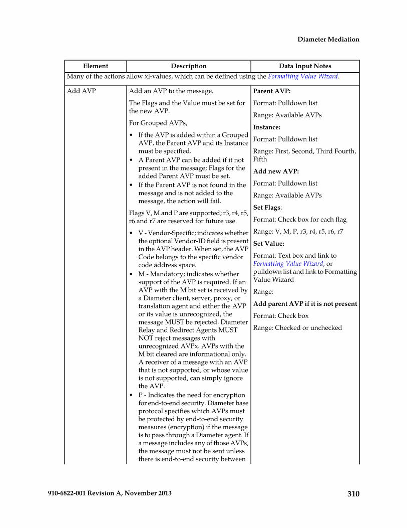
Data Input NotesDescriptionElementMany of the actions allow xl-values, which can be defined using the Formatting Value Wizard.
Parent AVP:Add an AVP to the message.Add AVP
The Flags and the Value must be set forthe new AVP.
Format: Pulldown list
Range: Available AVPsFor Grouped AVPs, Instance:• If the AVP is added within a Grouped
AVP, the Parent AVP and its Instancemust be specified.
Format: Pulldown list
Range: First, Second, Third Fourth,Fifth• A Parent AVP can be added if it not
present in the message; Flags for theadded Parent AVP must be set.
Add new AVP:
Format: Pulldown list• If the Parent AVP is not found in themessage and is not added to themessage, the action will fail.
Range: Available AVPs
Set Flags:Flags V, M and P are supported; r3, r4, r5,r6 and r7 are reserved for future use. Format: Check box for each flag
Range: V, M, P, r3, r4, r5, r6, r7• V - Vendor-Specific; indicates whetherthe optional Vendor-ID field is present Set Value:in the AVP header. When set, the AVP
Format: Text box and link toFormatting Value Wizard, or
Code belongs to the specific vendorcode address space.
pulldown list and link to FormattingValue Wizard
• M - Mandatory; indicates whethersupport of the AVP is required. If anAVP with the M bit set is received by Range:a Diameter client, server, proxy, or
Add parent AVP if it is not presenttranslation agent and either the AVPor its value is unrecognized, the Format: Check boxmessage MUST be rejected. Diameter
Range: Checked or uncheckedRelay and Redirect Agents MUSTNOT reject messages withunrecognized AVPx. AVPs with theM bit cleared are informational only.A receiver of a message with an AVPthat is not supported, or whose valueis not supported, can simply ignorethe AVP.
• P - Indicates the need for encryptionfor end-to-end security. Diameter baseprotocol specifies which AVPs mustbe protected by end-to-end securitymeasures (encryption) if the messageis to pass through a Diameter agent. Ifa message includes any of those AVPs,the message must not be sent unlessthere is end-to-end security between
310910-6822-001 Revision A, November 2013
Diameter Mediation

Data Input NotesDescriptionElementthe originator and the recipient of themessage.
Parent AVP:Delete a specified AVP in the message.Delete AVP
If the Instance of the specified AVP is All,the action is applied to all instances of theAVP or Grouped AVP in the message.
Format: Pulldown list
Range: Available AVPs
Instance:If the specified AVP is within a GroupedAVP, the Parent AVP and its Instancemust be specified.
Format: Pulldown list
Range: First, Second, Third Fourth,FifthIf the specified AVP is the last AVP within
the Grouped AVP, the action can bedefined to also delete the Parent AVP. Delete AVP:
Format: Radio button for Instancewith pulldown list; radio button forIf the specified AVP is a Grouped AVP,
the Grouped AVP and all of the AVPswithin the group are deleted. With the value with text box or
pulldown list and link to FormattingValue WizardIf the deleted AVP has been the last AVP
within the Grouped AVP, then Delete Range:parent AVP if it is empty can be checkedto delete the Parent AVP as well. Instance: First, Second, Third,
Fourth, Fifth, AllIf the specified AVP is not found in themessage, the Delete AVP action isconsidered to be successful.
With the value: Text, or pulldownlist values that vary with selectedAVP to delete (see Formatting ValueWizard)
Delete parent AVP if it is empty
Format: Check box
Range: Checked or unchecked;default is checked
Save AVP:Store a specified top-level AVP from themessage into the buffer associated with
Save AVP
Format: Pulldown list; radio buttonfor Instance with pulldown list;the transaction. A saved AVP is stored in
the buffer as long as the transaction exists. radio button for With the value withSaved AVPs can be accessed through theFormatting Value Wizard as corresponding
text box or pulldown list and link toFormatting Value Wizard
Linking-AVPs with the same AVP andinstance number. Range:
Pulldown list: Available AVPsIf the Instance of the specified AVP is All,the action saves all instances of the AVPin the message.
Instance: First, Second, Third,Fourth, Fifth, All
Note: A grouped AVP can be saved andrestored, but sub-AVPs within the stored
With the value: Text, or pulldownlist values that vary with selected
311910-6822-001 Revision A, November 2013
Diameter Mediation

Data Input NotesDescriptionElementAVP to delete (see Formatting ValueWizard)
or restored grouped AVP cannot beretrieved (such as [email protected]["name"][index].avp["name"][index]),modified, or removed.
If the same AVP is saved multiple times(the action is applied multiple times), thesaved value is overwritten each time theAVP is saved.
If the specified AVP is not found in themessage, the Save AVP action isconsidered to have failed.
Restore AVP:Restore a top-level AVP that has beenpreviously stored. AVPs can be restored
Restore AVP
Format: Pulldown listin the message by either appending eachAVP to the message or by replacing all ofthe same existing AVPs.
Range: Available AVPs
Instance:The instance number of the saved AVPmust be specified, to find the appropriateLinking-AVP (LAVP) that was stored.
Format: Pulldown list
Range: First, Second, Third Fourth,FifthNote: A Grouped AVP can be saved and
restored, but sub-AVPs within the stored Delete before restore:or restored Grouped AVP cannot be Format: Check boxretrieved (such as [email protected]["name"][index].avp["name"][index]),modified, or removed.
Range: Checked, unchecked; defaultis unchecked.
Set LAVP - Specifies the LAVP tobe set into the buffer associated withthe transaction.
Allows constructing a top-levelnon-Grouped AVP by setting the Flagsand specifying the value, and placing itinto the buffer associated with the
Set LAVP
Format: Pulldown listDiameter transaction. The AVP can beaccessed as a Linking-AVP through theFormatting Value Wizard.
Range: All non-Grouped AVPs fromthe dictionary
The value is stored in the buffer as longas the transaction exists. The LAVP canbe used for the Restore AVP action.
Default: First non-Grouped AVPdefinition from the dictionary
Instance - The instance number ofthe AVP within the buffer of thetransaction.
• Instance - A new AVP overwrites anyexisting AVP with the same instancenumber. Format: Pulldown list
• Set Value Range: First, Second, Third, Fourth,Fifth• The Input field is available when
the selected LAVP has a dataformat other than "Enumerated". Default: First
Set Flags - (see Flag definitions inAdd AVP)
312910-6822-001 Revision A, November 2013
Diameter Mediation

Data Input NotesDescriptionElement• If the flag must be set, the flag is
checked and disabled.• The Pulldown list is available when
the selected LAVP has the dataformat "Enumerated". • If the flag must not be set, the
flag is unchecked and disabled.• An error message appears if theentered value of the Input field is • If the flag can be set, the check
box is available to be changed.not an x1-value and does notcorrespond to the data formatrequired by the selected AVP. Format: Check boxes for the flags
Range: V, M, P, r3, r4, r5, r6, r7• Value type: Select the type of value
that can be assigned to this Default: From the dictionaryLinking-AVP. Possible value types are Set Value - Specifies the value of the
LAVP.the same as those for the Right valuein the Conditions section of this page.
Input field• Default Value: Default value to assign
to this Linking-AVP and to display on Format: Value entered through theFormatting Value Wizard page (clickthe Wizard link).
the Rule Sets page. Enter a 1 to 255character string.
Range: Values available in theFormatting Value Wizard.
• Descr: Add text here to describe thisAVP. This description appears on theRule Sets page. A maximum of 255characters can be entered.
Default: N/A
Pulldown list:• Optional: Click to make this AVP
optional on the Rule Sets page. Format: Pulldown list
Range: All of the values of thecorresponding Enumerated Type
• Delete: Click to delete an existingLinking-AVP.
Default: First value of theEnumerated Type
Actions that allow modifying an AVP
If the specified AVP is not found in the message, the action is considered to have failed.
Parent AVP:Replace an AVP definition with a newone, keeping the original AVP value and
Change AVP Code
Format: Pulldown listflag that are not strictly defined in thedictionary (that can be set). Range: Available AVPs
Allows changing the Code of the specifiedAVP and modifying its Flags.
Instance:
Format: Pulldown list
Range: First, Second, Third Fourth,Fifth
Old AVP:
Format: Pulldown list; radio buttonfor Instance with pulldown list;radio button for With the value with
313910-6822-001 Revision A, November 2013
Diameter Mediation

Data Input NotesDescriptionElementtext box or pulldown list and link toFormatting Value Wizard
Range:
Pulldown list: Available AVPs
Instance: First, Second, Third,Fourth, Fifth
With the value: Text, or pulldownlist values that vary with selectedAVP (see Formatting Value Wizard)
New AVP
Format: Pulldown list
Range: Available AVPs
Parent AVPAllows setting, clearing, and keeping theoriginal value of AVP flags.
Change AVP Flags
Format: Pulldown listFlags V, M and P are supported; r3, r4, r5,r6 and r7 are reserved for future use. Range: Available AVPs
Instance - The instance number ofthe AVP within the buffer of thetransaction.
• V - Vendor-Specific; indicates whetherthe optional Vendor-ID field is presentin the AVP header. When set, the AVPCode belongs to the specific vendorcode address space.
AVP
Format: Pulldown list; radio buttonfor Instance with pulldown list;• M - Mandatory; indicates whether
support of the AVP is required. If an radio button for With the value withAVP with the M bit set is received by text box or pulldown list and link toa Diameter client, server, proxy, or Formatting Value Wizard; Set Flag,translation agent and either the ABP Clear Flag, and Keep original radio
buttons for flags.or its value is unrecognized, themessage MUST be rejected. Diameter
Range:Relay and Redirect Agents MUSTNOT reject messages with Pulldown list: Available AVPsunrecognized AVPx. AVPs with the
Instance: First, Second, Third,Fourth, Fifth
M bit cleared are informational only.A receiver of a message with an AVPthat is not supported, or whose value With the value: Text, or pulldown
list values that vary with selectedAVP (see Formatting Value Wizard)
is not supported, can simply ignorethe AVP.
• P - Indicates the need for encryptionfor end-to-end security. Diameter base Flags: V, M, P, r3, r4, r5, r6, r7protocol specifies which AVPs mustbe protected by end-to-end securitymeasures (encryption) if the messageis to pass through a Diameter agent. Ifa message includes any of those AVPs,the message must not be sent unless
314910-6822-001 Revision A, November 2013
Diameter Mediation

Data Input NotesDescriptionElementthere is end-to-end security betweenthe originator and the recipient of themessage.
Parent AVP:Allows overwriting of the value of anAVP.
Set AVP Value
Format: Pulldown list
Range: Available AVPs
Instance:
Format: Pulldown list
Range: First, Second, Third Fourth,Fifth
AVP:
Format: Pulldown list; radio buttonfor Instance with pulldown list;radio button for With the value withtext box or pulldown list and link toFormatting Value Wizard
Range:
Instance: First, Second, Third,Fourth, Fifth
With the value: Text, or pulldownlist values that vary with selectedAVP (see Formatting Value Wizard)
Set Value:
Format: Text box or pulldown listand link to Formatting Value Wizard
Range: Text, or pulldown list valuesthat vary with selected AVP (seeFormatting Value Wizard)
Parent AVP:Strips the defined number of charactersfrom either the beginning or the ending
Strip from AVPValue Format: Pulldown listof the AVP value. This action can be used
in combination with the Prefix/Suffix toAVP Value action.
Range: Available AVPs
Instance:
Format: Pulldown list
Range: First, Second, Third Fourth,Fifth
AVP:
Format: Pulldown list; radio buttonfor Instance with pulldown list;
315910-6822-001 Revision A, November 2013
Diameter Mediation

Data Input NotesDescriptionElementradio button for With the value withtext box and link to Formatting ValueWizard
Range:
Pulldown list: Available AVPs
Instance: First, Second, Third,Fourth, Fifth
With the value: Text (see FormattingValue Wizard)
Strip from:
Format: Radio buttons, text box
Range: Radio button for Beginningof the value; radio button for End ofthe value; text - number ofcharacters to strip
Parent AVP:Add the defined data as a prefix or suffixto the AVP value. This action can be used
Prefix/Suffix toAVP Value Format: Pulldown listin combination with the Strip for AVP
Value action. Range: Available AVPs
Instance:
Format: Pulldown list
Range: First, Second, Third Fourth,Fifth
AVP:
Format: Pulldown list; radio buttonfor Instance with pulldown list;radio button for With the value withtext box and link to FormattingValue Wizard; radio buttons forPrefix or Suffix; text box for prefixor suffix with link to FormattingValue Wizard
Range:
Pulldown list: Available AVPs
Instance: First, Second, Third,Fourth, Fifth
With the value: Text box (seeFormatting Value Wizard)
Radio buttons: Prefix to the value,Suffix to the value
316910-6822-001 Revision A, November 2013
Diameter Mediation

Data Input NotesDescriptionElementText: The prefix or suffix (seeFormatting Value Wizard)
Parent AVP:Use a defined pattern to locate a field inthe AVP value, and replace the data in thefield with the specified new data.
Substitute in AVPValue Format: Pulldown list
Range: Available AVPs
Instance:
Format: Pulldown list
Range: First, Second, Third Fourth,Fifth
AVP:
Format: Pulldown list; radio buttonfor Instance with pulldown list;radio button for With the value withtext box and link to Formatting ValueWizard
Range:
Pulldown list: Available AVPs
Instance: First, Second, Third,Fourth, Fifth
With the value: Text box (seeFormatting Value Wizard)
Pattern:
Format: Text box
Range: Patten to locate the field
Replacement:
Format: Text box
Range: Text of the replacement data(see Formatting Value Wizard)
Other Actions
Format: Pulldown list for SelectMessage Copy Configuration Setfield
Trigger Diameter Message Copy for themessage, based on the values in theMessage Copy Configuration Set that isspecified for the Action. See Message CopyConfiguration Set configuration.
Message Copy
Range: Default; configured MessageCopy Configuration Sets
Default: "-Select-"
Format: Pulldown listNote: The value needs to be set at thetime the new Rule Template is defined.
Execute Ruletemplate
317910-6822-001 Revision A, November 2013
Diameter Mediation

Data Input NotesDescriptionElementRange: Available Rule Templates in"Test" and "Active" states
Only Rule Templates in "Test" or "Active"state are listed in the pulldown list.
Default: First Rule Template Namein the list
This field is displayed on DiameterMediation Rule Template Insert and Editpages, but not on the View page.
N/AExits from the Execution Trigger,bypassing any subsequent Rule Setassociated with it.
Exit from ExecutionTrigger
Table 123: Rule Template Condition Operators describes the Operators that can be used between the LeftValue and the Right value in a Rule Template Condition.
The value can be an AVP, another part of a Diameter message, a constant, or an internal variable.
Table 123: Rule Template Condition Operators
Returns true when...OperatorType
Operator
Example of use
Value exists AND equals...Genericequals (==)
@msg.command.code==316
Value does not exist OR does not equal...Genericdoes not equal (!=)
@msg.command.code!=316
Value exists AND begins with (longest match)...Stringbegins with (longest match) (=^^)
@msg.avp["Destination-Realm"]=^^test
Value exists AND begins with...Stringbegins with (=^)
@msg.avp["Destination-Realm"]=^testlb
Value does not exist OR does not begin with...Stringdoes not begin with (!=^)
@msg.avp["Destination-Realm"]!=^testlb
Value exists AND ends with...Stringends with (=$)
@msg.avp["Origin-Host"][1]=$entity.com
Value does not exist OR does not end with...Stringdoes not end with (!=$)
@msg.avp["Origin-Host"][1]!=$entity.com
Value exists AND matches the regularexpression...
Stringregular expression match (=~)
@msg.avp[Session-Id]!=~.*\.example\..*
Value does not exist OR does not match theregular expression...
Stringregular expression does not match(!=~)
@msg.avp["Session-Id"]!=~.*\example\..*
318910-6822-001 Revision A, November 2013
Diameter Mediation

Returns true when...OperatorType
Operator
Example of use
Value exists AND is less than...Numericless than (<)
@msg.avp["Validity-Time"]<30
Value exists AND is greater than...Numericgreater than (>)
@msg.avp["Validity-Time"]>30
Value exists AND is less than or equal to...Numericless than or equal to (<=)
@msg.avp["Validity-Time"]<=30
Value exists AND is greater than or equal to...Numericgreater than or equal to (>=)
@msg.avp["Validity-Time"]>=30
Value exists AND is within...Subnetis within
@msg.avp["Served-Party-IP-Address] is within192.168.0.0/24
Value does not exist OR is not within...Subnetis not within
@msg.avp["Served-Party-IP-Address] is not within192.168.0.0/24
AVP specified as Left value exists...exists
@msg.avp["Vendor-Specific-Application"] exists
AVP specified as Left value does not exist...does not exist
@msg.avp["Vendor-Specific-Application"] doesnot exist
AVP specified as Left value exists AND it is notempty/non-zero...
is true
@msg.avp["Disconnect-Cause"] is true
AVP specified as Left value does not exist OR itis empty/0...
is false
@msg.avp["Disconnect-Cause"] is false
"is true" and "is false" work only on numbers (Integer32, Integer32, Unsigned32, Unsigned64, Float32,Float64, Enumerated, Time) and strings (OctetString, UTF8String, DiameterIdentity, DiameterURI).
For an IP Address, "is true" always succeeds; the address can be converted to a string that is neverempty.
If the condition cannot be evaluated (for example, the AVP does not exist or the xl-value isincompatible), then "is true" will fail and "is false" will succeed.
Based on the type of operator selected, the Left value and the Right value are converted according tothe rules in Table 124: Rule Template Condition Conversion Rules.
319910-6822-001 Revision A, November 2013
Diameter Mediation

Table 124: Rule Template Condition Conversion Rules
ConversionRight valueType
OperatorType
Left value Type
Convert Left value and Right value to strings.-String-
Convert Left value and Right value to numbers.-Numeric-
Convert Left value to an IP address.-Subnet-
Convert Right value to a subnet
No conversion is needed.StringGenericString
No conversion is needed.NumericGenericNumeric
No conversion is needed.IP addressGenericIP address
Convert Left value to a number.NumericGenericString
Convert Right value to a number.StringGenericNumeric
Convert Right value to an IP address.StringGenericIP address
Convert Left value to an IP address.IP addressGenericString
Conversion cannot be done.None of these cases
Operators by Type (see also Table 123: Rule Template Condition Operators)
=~, !=~, =^, =^^, !=^, =$, !=$String
<, >, <=, >=Numeric
is within, is not withinSubset
==, !=Generic
The conversion fails if the input value is reasonably not convertible to the new format (such as thenumeric input cannot be converted to an IP Address).
If the conversion is impossible or fails, the condition is evaluated to false unless the operator is negated(begins with !, or "is not within").
For float to string conversion, the double argument is rounded and converted to decimal notation inthe style [-]ddd.dddddd, with 6 characters of precision. If the conversion does not fit into 21 characters,then it will fail.
For IPv6 to string conversion, the following rules apply:
• Leading zeros are ignored (01->1)• Lowercase to uppercase (ffff->FFFF)• 1:0:0:0:0:0:0:0->1:0:0:0:0:0:0:0• 1::2->1:0:0:0:0:0:0:2• ::ffff->0:0:0:0:0:0:0:FFFF• ffff::->FFFF:0:0:0:0:0:0:• ::->0:0:0:0:0:0:0:0
320910-6822-001 Revision A, November 2013
Diameter Mediation

Viewing Rule Templates
Use this procedure to view all existing Rule Templates.
Select Diameter > Mediation > Rule Templates.The Diameter > Mediation > Rule Templates page appears.
Adding a Rule Template
Use this procedure to define a new Rule Template. A maximum of 64 Rule Templates can be defined.
There are three sections of the Diameter > Mediation > Rule Templates [Insert] page: Settings,Conditions, and Actions. For a list of Rule Template elements and their definitions, see Rule Templateelements.
After the definition is complete and the Rule Template State is set to "Active" or "Test", this RuleTemplate appears as a Rule Set in the Diameter > Mediation > Rule Sets menu folder.
1. If Mediation-Triggered Message Copy will be used (the Message Copy Action will be selected inone or more Rule Templates), the following Diameter Configuration is required before each Actioncan be configured.a) Configure one or more Route Groups that will be used for one or more Route Lists for the
Message Copy DAS.b) Configure one or more Route Lists for the DAS.c) Configure one or more Message Copy Configuration Sets that can be assigned to one or more
Rule Template Message Copy Actions.
2. Verify that the required Diameter Mediation Enumeration Types, AVP Dictionary entries, andVendors have been defined in the system.Use the following GUI pages to view the entries, and to access the GUI pages to enter, change, ordelete entries as needed
• Enumerations• All-AVP Dictionary• Vendors
3. Select Diameter > Mediation > Rule Templates.The Diameter > Mediation > Rule Templates page opens.
4. Click the Insert button.The Diameter > Mediation > Rule Templates [Insert] page opens.
If the maximum number of Rule Templates (100) already exist in the system, the Rule Templates[Insert] page will not open, and an error message is displayed.
5. Enter the Settings values for the Rule Template.a) Enter the name for the Rule Template in the Name text box.
The Name describes the purpose of the Rule Template.b) The Message type support for the Rule Template cannot be provisioned.
Request and Answer are both supported.
321910-6822-001 Revision A, November 2013
Diameter Mediation

6. Enter the values to define up to 5 Conditions in the Rule Template.
Note: A Rule Template can be defined with no Conditions. It will unconditionally match for allprocessed messages.
The order in which conditions appear on the Diameter > Mediation > Rule Templates pagedetermines the order in which the conditions are processed. The Up and Down buttons are usedto change the order of processing.
The Fast Search check mark or stop symbol displayed for a condition is determined by the Operatorand the Optional fields. A check mark appears for Fast Search when the Operator is either "equals","begins with-longest match", or "begins with", and the Optional element is not check marked.
A check mark in Optional indicates that a matching expression is optional. This means that theuser can leave this condition's Value field blank on the Diameter > Mediation > Rule Set page,and this condition will then not be used during message processing.
a) Enter a Name for the condition. This name appears on the generated Rule Set page after thisRule Template is saved.
b) Enter a Left value in the text box, or use the Formatting Value Wizard to select the componentsof the Left value.The Left value appears in the text box.
c) Select an Operator from the pulldown menu.d) Select a Right value from the pulldown list.e) Provide a Default value for the Right value that will appear on the Rule Set page that is
generated from the Rule Template.f) Click the appropriate check boxes to display a check mark in the boxes that apply for this Rule
Template.
Click the Case sensitive check box to indicate that the values must match in case as well ascontent.
Click the Optional check box to indicate that the user can decide to exclude the matchingexpression form the condition set by leaving the Right value empty.
Click the Fixed check box to indicate that the Right value cannot be changed in the rule.
g) To add another condition, click Add and repeat the substeps in this step for each additionalcondition.
7. Enter the values to define one or more Actions in the Rule Template.When any defined Conditions are met, the Actions specified in this section of the page are taken.At least one Action must be specified for a Rule Template.a) From the New Action pulldown list, select an Action to take for this Rule Template.b) Click [Add] to open the GUI fields for the selected Action.c) Enter the information in the fields. The fields are described in Rule Template elements.
8. When the Rule Template definition is complete, click:
• OK to save the Rule Template and return to the Diameter > Mediation > Rule Templates page.The Rule Template Name appears in the list on the page.
• Apply to save the Rule Template and remain on the Diameter > Mediation > Rule Templates[Insert] page for additional changes.
• Cancel to return to the Diameter > Mediation > Rule Templates page without saving the RuleTemplate.
322910-6822-001 Revision A, November 2013
Diameter Mediation

If OK or Apply is clicked and any of the following conditions exist, an error or warning messageappears:
• Any of the Default value fields in the Conditions contain a value that cannot fit into the rangeof the selected Right value with a supported Operator.
• Any of the Default value fields in the Conditions contain a value that is not valid or is not thecorrect format for the selected Right value with a supported Operator.
• Adding the new Rule Template would cause the maximum number (100) of Rule Templatesallowed in the system to be exceeded.
9. If you want to add online help to describe this Rule Template in its generated Rule Set, performthe Adding online help to a Rule Template procedure. Then continue with Step 10.
10. When the Rule Template definition is complete, go to the Diameter Mediation State & Propertiespage.a) Change the Rule Template State from Development to either Test or Active.b) Set the Action Error Handling property.After the Rule Template definition is completed and saved, the Rule Template state and propertiescan be changed to make the Rule Template available for testing and to generate the Rule Set fromthe Rule Template.
The Rule Template state can be changed to Test to allow testing, provisioning of the Rule Set data,and associating the Rule Set with a Trigger (see Triggers) before the Rule Set is used in live traffic.
The state can be changed to Active after the testing is successful, the Rule Set data is provisioned,the Rule Set is associated with a Trigger, and the Rule Set is ready to use in live traffic.
11. If one or more Rule Template Actions for Message Copy have been configured, go to the Diameter> Configuration > System Options page, select the Message Copy Options tab, and select theEnabled radio button for the Message Copy Feature element.
Adding online help to a Rule Template
When a Rule Template is created, online help can be added to the Rule Template to describe it in itsgenerated Rule Set.
After online help is added, when the user clicks the context-sensitive help icon in the upper rightcorner of the associated Diameter > Mediation > Rule Sets {name} page, this online help explainshow to use the Diameter > Mediation > Rule Sets {name} page to configure the Rule Set.
This help is standalone, and is not part of the online help provided by Tekelec as part of the Mediationfeature.
Use this procedure to add context-sensitive online help to an existing Rule Template:
1. Select Diameter > Mediation > Rule Templates.
The Diameter > Mediation > Rule Templates page appears.
2. Select the Rule Template Name to which online help will be added.3. Click Set Help.
The Diameter > Mediation > Rule Templates [Set Help] page appears.
4. Change the contents of the Title box to an appropriate title for this help.
323910-6822-001 Revision A, November 2013
Diameter Mediation
The Rule Template Name appears in the Title box as the default.
5. In the Text field, add specific details on how to configure a rule using this Rule Set, such as aprocedure and result. You can also add detail on how the various fields interrelate, and provideany cautions to prevent loss of data.
6. To see how the help text you have entered will look from the Rule Set page, click Preview.
A separate window opens and displays the help text.
Close the preview window when you are finished previewing the help text.
7. When the help page is complete, click:
• OK to save the help page and return to the Diameter > Mediation > Rule Templates page.• Apply to save the changes and remain on the Diameter > Mediation > Rule Templates [Set
Help] page for additional changes.• Cancel to return to the Diameter > Mediation > Rule Templates page without saving any
changes.
The new help text is now available from the help icon on the Diameter > Mediation > Rule Sets{name} page for this Rule Template.
Rule Templates Help elementsWhen Set Help is clicked for an existing Rule Template on the Diameter Mediation Rule Templatespage, the following information appears:
Data Input NotesDescriptionElement
Format: Text stringTitle to appear at the top of theHelp page. This field is requiredwhen providing Help.
Title
Range: 1-64 characters
Format: Text string (HTML tagsallowed)
Detailed explanation of this RuleSet: how to use it and descriptionof any interrelated features.
Text
Range: 1 - 1500 characters
(Generated and used by software)Path
Copying a Rule Template
Use this procedure to copy an existing Rule Template and save it as a new Rule Template. For a listof Rule Template elements and their definitions, see Rule Template elements.
1. Select Diameter > Mediation > Rule Templates.The Diameter > Mediation > Rule Templates page appears.
2. Select the Rule Template that you want to copy.3. Click Copy.
The Diameter > Mediation > Rule Templates [Copy] page appears.
If the maximum number of Rule Templates (100) already exist in the system, the Rule Templates[Copy] page will not open, and an error message is displayed.
324910-6822-001 Revision A, November 2013
Diameter Mediation

4. Enter a different Rule Template Name for the new Rule Template.5. Make any changes as needed.6. Click:
• OK to save the definition and return to the Diameter > Mediation > Rule Templates page.• Apply to save the definition and remain on the Diameter > Mediation > Rule Templates [Copy]
page.• Cancel to return to the Diameter > Mediation > Rule Templates page without saving any
changes.
Changing a Rule Template
Use this procedure to change values for an existing Rule Template (for a list of Rule Template elementsand their definitions, see Rule Template elements).
When a Rule Template is in the Development state, all elements can be changed.
After the Rule Template state has been changed to Test or Active, only the following elements can bechanged. The Rule Template state must be set back to Development to change any other elements (allprovisioning of rules for the Rule Template will be lost when the state is changed back to Development).(See State and Properties.)
• Rule Template Name• Name of the Conditions• Default value of the Conditions (except when the Fixed box has been checked)• Description of the Condition• Default value of the Actions (except for the value of the "Execute Rule Template")
1. Select Diameter > Mediation > Rule Templates.
The Diameter > Mediation > Rule Templates page appears.
2. Click Edit on the Rule Template row to be changed.
The Diameter > Mediation > Rule Templates [Edit] page appears.
3. Change Conditions and Actions as needed.4. Click:
• OK to save the changes and return to the Diameter > Mediation > Rule Templates page.• Apply to save the changes and remain on the Diameter > Mediation > Rule Templates [Edit]
page.• Cancel to return to the Diameter > Mediation > Rule Templates page without saving any
changes.
Importing a Rule Template
A Rule Template can be imported into the DSR system using the Import function on the Diameter >Mediation > Rule Templates page.
Existing Rule Templates can be imported. Existing Rule Templates are previously defined RuleTemplates that have been exported from Diameter Mediation using the Export function.
325910-6822-001 Revision A, November 2013
Diameter Mediation

The Mediation version in the file selected for importing must be compatible with the DSR release intowhich the file is imported.
A successfully imported Rule Template file appears in the list on the Diameter > Mediation > RuleTemplates page, the Diameter > Mediation > State & Properties page, and as a Rule Set in theDiameter > Mediation > Rule Sets menu folder (no Rule Set is generated if the only Action is "ExecuteRule Template").
The imported Rule Template is automatically set to the "Test" state.
The Enumeration Types that are used in the Rule Template are imported, if they do not already existin the system.
If the selected Rule Template references another Rule Template (as an Execute Rule Template action)that is not already present in the system, the referenced Rule Template is also imported (unless thereis already a Rule Template with the same Name but a different definition).
Use the following procedure to import an existing Rule Template that is located outside of the DSRfile system (stored on a local computer):
1. Select Diameter > Mediation > Rule Templates.The Diameter > Mediation > Rule Templates page appears.
2. Click Import.The Diameter > Mediation > Rule Templates [Import] page appears.
If the maximum number of Rule Templates (100) already exist in the system, the Diameter >Mediation > Rule Templates [Import] page will not open, and an error message is displayed.
3. Click Browse to open the Choose File popup window.4. Navigate to the location of the Rule Template file you want to import, and select the file.5. With the Rule Template filename displayed in the File name field, click Open.
The filename appears in the Choose a file to import field.
6. Click Import File.
If the Import File button is clicked and any of the following conditions exist, the file is not importedand an error message appears:
• The selected file does not exist• The selected file is larger than 1 MB• The selected file has wrong .xml structure or missing data• The Mediation version of the file is not compatible with the DSR system into which the file is
being imported• The Name field of the imported Rule Template is empty• Any Operator field in a Condition contains an operator that is not valid• Any Right value field in a Condition• A value type specifies an Enumerated Type that is not defined either in the system or in the
imported file• A Condition or Action in the selected file includes an Enumerated Type that is already present
in the system, but that contains different Enumerated Type values• The selected file contains an Action that is not defined in the system• The selected file contains more than the allowed maximum number of Conditions (5)
326910-6822-001 Revision A, November 2013
Diameter Mediation

• A Condition in the selected file includes a Right value that is not supported by the selectedOperator
• The Right value of a Condition in the file is not a supported value type• The selected file contains more than the allowed maximum number of Actions (5), unless the
maximum number is exceeded because of automatically added final actions (some actionsactually result in multiple actions)
• Importing the file would cause the allowed maximum number of Rule Templates (100) in thesystem to be exceeded
• The selected Rule Template references another Rule Template (as an Execute Rule Templateaction) that is not present in the system
• The selected file contains mutually exclusive Actions (that cannot be used together in the sameRule Template)
Exporting a Rule Template
Use this procedure to export a Rule Template from within the DSR to an external location, such asyour hard drive or a memory stick.
The selected file is saved in .xml format, and contains the following information:
• The Rule Template without any provisioned data• All of the Enumeration Type definitions with the possible values to which the Rule Template refers• Mediation version number• Help pages related to the Rule Template
Note: The Export button is not available (grayed out) for Rule Templates that are in the "Development"state (see the Diameter > Mediation > State and Properties page).
1. Select Diameter > Mediation > Rule Templates.
The Diameter > Mediation > Rule Templates page appears.
2. Select the Rule Template Name row for the Rule Template to be exported.3. Click the Export button.
A File Download popup window appears.
4. Click Browse to pop up the Choose File window.5. Navigate to the location to which you want to export the Rule Template.6. Click Export File.
The selected file is saved to the specified location.
Deleting a Rule Template
When a Rule Template is deleted, it is removed from the entire system, including the Diameter >Mediation > State and Properties page, the Diameter > Mediation > Triggers page, and the Daimeter> Mediation > Rule Sets page.
Any Rule Sets that were generated from this Rule Template are also deleted automatically.
327910-6822-001 Revision A, November 2013
Diameter Mediation

If a Rule Set belonging to the selected Rule Template is enabled for live traffic ("Active" state on theState and Properties page), an error message appears indicating that the Rule Template cannot bedeleted as long as it is being used by the system for live traffic.
Use this procedure to delete an existing Rule Template.
1. Select Diameter > Mediation > Rule Templates.
The Diameter > Mediation > Rule Templates page appears.
2. Select the Rule Template Name of the Rule Template to be removed.3. Click Delete.4. A popup window appears to confirm the delete when the selected Rule Template is in the
"Development" state or the "Test" state (see the State and Properties page).
• Click OK to confirm the delete.• Click Cancel to cancel the delete function and return to the Diameter > Mediation > Rule
Templates page.
5. If the selected Rule Template has any data provisioned, another confirmation popup windowappears indicating that all of the provisioned data that belongs to any Rule Set generated from theRule Template will be deleted.
• Click OK to confirm the delete of the provisioned data.• Click Cancel to cancel the delete function and return to the Diameter > Mediation > Rule
Templates page.
Formatting Value Wizard
The Formatting Value Wizard is a popup window available from both the Diameter > Mediation >Rule Templates Insert/Edit/Copy pages and the Diameter > Mediation > Rule Sets Insert/Editpages. The wizard simplifies entry of xl-formatted strings, which require specific syntax coding. BothLog and Add Header functions require xl-formatted string coding.
An xl-formatted string can contain references to the state of the server, or to the message beingprocessed. For example, %@ruri.user refers to the user part of the Request URI within an xl-formattedstring. The references are replaced with their actual value before the log message is issued, or beforethe string is appended to the Request.
Formatting Value Wizard elements
When [wizard] is clicked, the information shown in Table 125: Formatting Value Wizard elements appears:
Table 125: Formatting Value Wizard elements
DescriptionElement
The value of the variable in xl-format.Value
The components of this value can be entered manually, by clicking onone or more specifiers, or both.
328910-6822-001 Revision A, November 2013
Diameter Mediation

DescriptionElement
List of elements that can be part of an xl-formatted string.Specifiers
A specifier is either a single item, or a group of items forming a sublist.Every specifier that is selected is put into the Value field where thecursor is currently located.
The Specifiers are described in Table 126: Formatting Value WizardSpecifiers.
The readable description of the xl-formatted string in the Value field.Preview
The specifiers described in Table 126: Formatting Value Wizard Specifiers can be used to create or updatethe variables in the Value field.
Note: [Index] that is either a [<number>] or [any] can be excluded from all of the expressions that referto the first instance of the AVP.
The instance number "any" can be present in the Left value of the Condition only once.
The instance number "any" can be present in the Right value of the Condition only once.
Table 126: Formatting Value Wizard Specifiers
Specifier
Preview Valuexl-formatted ValueSub-ItemsNew Line
<BR> (This causes a line break onthe GUI screen.)
\r\n
{"string constant"}string constantType the stringconstant
StringConstant
Preview Valuexl-formatted ValueSub-ItemsDiameterHead
{Version}@msg.versionVersion
{Message Length}@msg.lengthMessage Length
{R Command Flag}@msg.command.flags.RCommand Flags: R
{P Command Flag}@msg.command.flags.PCommand Flags: P
{E Command Flag}@msg.command.flags.ECommand Flags: E
{T Command Flag}@msg.command.flags.TCommand Flags: T
{r4 Command Flag}@msg.command.flags.r4Command Flags: r4
{r5 Command Flag}@msg.command.flags.r5Command Flags: r5
{r6 Command Flag}@msg.command.flags.r6Command Flags: r6
{r7 Command Flag}@msg.command.flags.r7Command Flags: r7
{Application ID}@msg.application_idApplication ID
{Hop-to-Hop Identifier}@msg.hbh_idHop-by-Hop Identifier
329910-6822-001 Revision A, November 2013
Diameter Mediation

Specifier
{End-to-End Identifier}@msg.e2e_idEnd-to-End Identifier
Sub-ItemsAVP
Parent AVP
Pulldown list containing all AVP definitions from the dictionary that have the type "Grouped".
Parent AVP Instance number
Pulldown list containing the index of the Parent AVP, if a Parent AVP is selected (First,Second, Third, Fourth, Fifth).
AVP
Pulldown list containing all AVP definitins from the dictionary (except for the case wherethe selected Parent AVP is grouped; then only those AVPs that belont the group are available).
AVP instance number
Pulldown list containing the indexes of AVP (First, Second, Third, Fourth, Fifth, Any).
AVP Component
Pulldown list containing the following components:
• Data• Data Length• AVP Code• Flag V• Flag M• Flag P• Flag r3• Flag r4• Flag r5• Flag r6• Flag r7• Vendor-ID
Flags V, M, and P are supported; flags r3, r4, r5, r6, and r7 are reserved for future use.
xl-formatted Value
@msg.avp[“name”]
@msg.avp[“name”][index]
@msg.avp[“name”][index].code
@msg.avp[“name”][index].flags.V
@msg.avp[“name”][index].flags.M
@msg.avp[“name”][index].flags.P
@msg.avp[“name”][index].flags.r3
330910-6822-001 Revision A, November 2013
Diameter Mediation

[email protected][“name”][index].flags.r4
@msg.avp[“name”][index].flags.r5
@msg.avp[“name”][index].flags.r6
@msg.avp[“name”][index].flags.r7
@msg.avp[“name”][index].vendor_id
@msg.avp[“name”][index].data
@msg.avp[“name”][index].data_length
@msg.avp[“name”][index].avp[“name”][index]
@msg.avp[“name”][index].avp[“name”][index].code
@msg.avp[“name”][index].avp[“name”][index].flags.V
@msg.avp[“name”][index].avp[“name”][index].flags.M
@msg.avp[“name”][index].avp[“name”][index].flags.P
@msg.avp[“name”][index].avp[“name”][index].flags.r3
@msg.avp[“name”][index].avp[“name”][index].flags.r4
@msg.avp[“name”][index].avp[“name”][index].flags.r5
@msg.avp[“name”][index].avp[“name”][index].flags.r6
@msg.avp[“name”][index].avp[“name”][index].flags.r7
@msg.avp[“name”][index].avp[“name”][index].vendor_id
@msg.avp[“name”][index].avp[“name”][index].data
@msg.avp[“name”][index].avp[“name”][index].data_length
Preview Value
{AVP:“Name”}
{AVP:“Name”[Index]}
{AVP:“Name”[Index].Code}
{AVP:“Name”[Index].Flag V}
{AVP:“Name”[Index].Flag M}
{AVP:“Name”[Index].Flag P}
{AVP:“Name”[Index].Flag r3}
{AVP:“Name”[Index].Flag r4}
{AVP:“Name”[Index].Flag r5}
{AVP:“Name”[Index].Flag r6}
{AVP:“Name”[Index].Flag r7}
{AVP:“Name”[Index].Vendor-ID}
331910-6822-001 Revision A, November 2013
Diameter Mediation
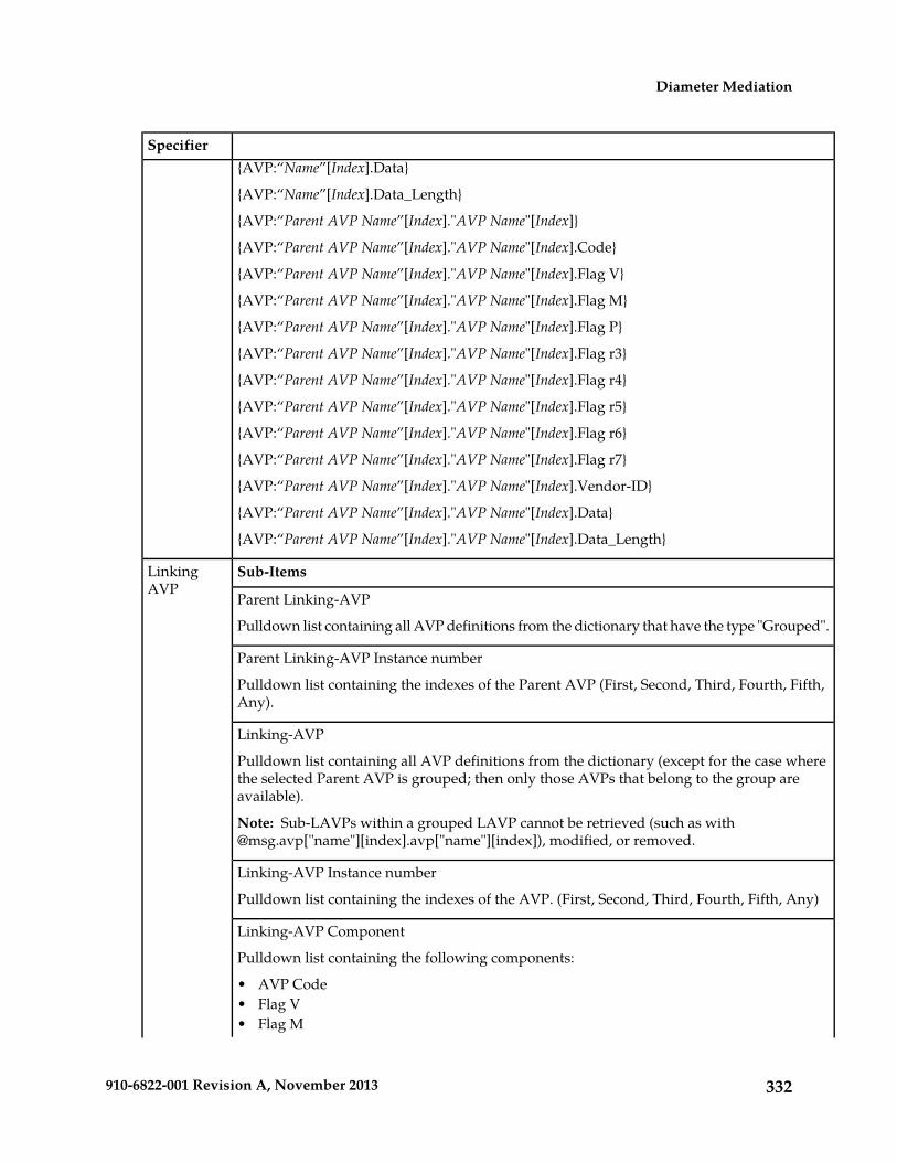
Specifier{AVP:“Name”[Index].Data}
{AVP:“Name”[Index].Data_Length}
{AVP:“Parent AVP Name”[Index]."AVP Name"[Index]}
{AVP:“Parent AVP Name”[Index]."AVP Name"[Index].Code}
{AVP:“Parent AVP Name”[Index]."AVP Name"[Index].Flag V}
{AVP:“Parent AVP Name”[Index]."AVP Name"[Index].Flag M}
{AVP:“Parent AVP Name”[Index]."AVP Name"[Index].Flag P}
{AVP:“Parent AVP Name”[Index]."AVP Name"[Index].Flag r3}
{AVP:“Parent AVP Name”[Index]."AVP Name"[Index].Flag r4}
{AVP:“Parent AVP Name”[Index]."AVP Name"[Index].Flag r5}
{AVP:“Parent AVP Name”[Index]."AVP Name"[Index].Flag r6}
{AVP:“Parent AVP Name”[Index]."AVP Name"[Index].Flag r7}
{AVP:“Parent AVP Name”[Index]."AVP Name"[Index].Vendor-ID}
{AVP:“Parent AVP Name”[Index]."AVP Name"[Index].Data}
{AVP:“Parent AVP Name”[Index]."AVP Name"[Index].Data_Length}
Sub-ItemsLinkingAVP
Parent Linking-AVP
Pulldown list containing all AVP definitions from the dictionary that have the type "Grouped".
Parent Linking-AVP Instance number
Pulldown list containing the indexes of the Parent AVP (First, Second, Third, Fourth, Fifth,Any).
Linking-AVP
Pulldown list containing all AVP definitions from the dictionary (except for the case wherethe selected Parent AVP is grouped; then only those AVPs that belong to the group areavailable).
Note: Sub-LAVPs within a grouped LAVP cannot be retrieved (such as [email protected]["name"][index].avp["name"][index]), modified, or removed.
Linking-AVP Instance number
Pulldown list containing the indexes of the AVP. (First, Second, Third, Fourth, Fifth, Any)
Linking-AVP Component
Pulldown list containing the following components:
• AVP Code• Flag V• Flag M
332910-6822-001 Revision A, November 2013
Diameter Mediation

Specifier• Flag P• Flag r3• Flag r4• Flag r5• Flag r6• Flag r7• Vendor ID• Data• Data Length
Flags V, M, and P are supported; flags r3, r4, r5, r6, and r7 are reserved for future use.
xl-formatted Value
@store.avp[“name”]
@store.avp[“name”][index]
@store.avp[“name”][index.code]
@store.avp[“name”][index].flags.V
@store.avp[“name”][index].flags.M
@store.avp[“name”][index].flags.P
@store.avp[“name”][index].flags.r3
@store.avp[“name”][index].flags.r4
@store.avp[“name”][index].flags.r5
@store.avp[“name”][index].flags.r6
@store.avp[“name”][index].flags.r7
@store.avp[“name”][index].length
@store.avp[“name”][index].vendor_id
@store.avp[“name”][index].avp[“name”][index]
@store.avp[“name”][index].avp[“name”][index].code
@store.avp[“name”][index].avp[“name”][index].flags.V
@store.avp[“name”][index].avp[“name”][index].flags.M
@store.avp[“name”][index].avp[“name”][index].flags.P
@store.avp[“name”][index].avp[“name”][index].flags.r3
@store.avp[“name”][index].avp[“name”][index].flags.r4
@store.avp[“name”][index].avp[“name”][index].flags.r5
@store.avp[“name”][index].avp[“name”][index].flags.r6
@store.avp[“name”][index].avp[“name”][index].flags.r7
@store.avp[“name”][index].avp[“name”][index].vendor-id
333910-6822-001 Revision A, November 2013
Diameter Mediation

[email protected][“name”][index].avp[“name”][index].data
@store.avp[“name”][index].avp[“name”][index].data_length
Preview Value
{LAVP:“Name”}
{LAVP:“Name”[Index]}
{LAVP:“Name”[Index].Code}
{LAVP:“Name”[Index].Flag V}
{LAVP:“Name”[Index].Flag M}
{LAVP:“Name”[Index].Flag P}
{LAVP:“Name”[Index].Flag r3}
{AVP:“Name”[Index].Flag r4}
{AVP:“Name”[Index].Flag r5}
{LAVP:“Name”[Index].Flag r6}
{LAVP:“Name”[Index].Flag r7}
{LAVP:“Name”[Index].Vendor-ID
{LAVP:“Name”[Index].Data}
{LAVP:“Name”[Index].Data_Length}
{LAVP:“Parent LAVP Name”[Index]."LAVP Name"[Index]}
{LAVP:“Parent LAVP Name”[Index]."LAVP Name"[Index].Code}
{LAVP:“Parent LAVP Name”[Index]."LAVP Name"[Index].Flag V}
{LAVP:“Parent LAVP Name”[Index]."LAVP Name"[Index].Flag M}
{LAVP:“Parent LAVP Name”[Index]."LAVP Name"[Index].Flag P}
{LAVP:“Parent LAVP Name”[Index]."LAVP Name"[Index].Flag r3}
{LAVP:“Parent LAVP Name”[Index]."LAVP Name"[Index].Flag r4}
{LAVP:“Parent LAVP Name”[Index]."LAVP Name"[Index].Flag r5}
{LAVP:“Parent LAVP Name”[Index]."LAVP Name"[Index].Flag r6}
{AVP:“Parent LAVP Name”[Index]."LAVP Name"[Index].Flag r7}
{LAVP:“Parent LAVP Name”[Index]."LAVP Name"[Index].Vendor-ID}
{LAVP:“Parent LAVP Name”[Index]."LAVP Name"[Index].Data}
{LAVP:“Parent LAVP Name”[Index]."LAVP Name"[Index].Data_Length}
Preview Valuexl-formatted ValueSub-ItemsFunctions
{Length of (<string>)}strlen(<string>Length of
334910-6822-001 Revision A, November 2013
Diameter Mediation

Specifier
Used to determine the length of a number and then to determine if additional digits shouldbe prepended or removed.
For example, if a 7-digit number is received, a default area code might have to be prependedto the number.
“Length of” always works on string types. If the parameter happens to be a number, then itwill be automatically treated as a string by these functions. Hence, strlen(123) will work thesame as strlen("123"), and return 3.
The input of the function "string" might include other xl-values such as contants, DiameterHeader parts, AVP or LAVP parts, or other functions.
{Hash (<string>), <range>)}hash(<string>, <range>)Hash
Used for making a routing decision based on the hash generated on the "session-id" AVP.This AVP is present in charging messages such as ACR and CCR.
For example, if session-id hashes to 1, then set dest-host to host1, if it hashes to 2, then setdest-host to host2.
Because all messages in a session need to go to the same host and they all have the samesession-id, the mechanism can be used to send them to the same host without maintainingstate.
The input of the function "string" might include other xl-values such as contants, DiameterHeader parts, AVP or LAVP parts, or other functions.
Substring (<string>,<position>,<length>)}
substr(<string>,<position>,<length>)
Substring
Postion can be negative,(counted from the end).
Used to inspect a part of a string or number and make changes if needed.
For example, if the first 4 characters match "+011", then delete the characters.
“Substring” works always on string types.
The input of the function "position" specifies the position(character) at whch the counting ofthe substring will start. Position 0 inidcates the first character of the string. -1 indicates thelast character of the string.
The input of the function "length" specifies the number of characters to include in the substring.
The specified substring will be extracted.
For example: substr(@msg.avp["APN-OI-Replacement"][1],0,5)
{<x>hours}hour2sec(<hours>)X hours
{<y>minutes}min2sec(<minutes>)Y minutes
{GMT time}time( )GMT
Can be used to perform time of day routing.
335910-6822-001 Revision A, November 2013
Diameter Mediation

SpecifierCertain AVPs carry time, which can be compared against a specified hour and minute toperform time of day routing.
The inputs "hours" or "minutes" might include other xl-values.
Provide the ability toperform mathematicaloperations on the AVP.
Operators • +• +• •- -
• Plus• Minus
\<number>\<number>Number of occurenceof the back reference:
BackReference
input field for onedigit; default is 0.
Because Back Reference can be part of only a replacement string, this specifier is presentedonly for the Substitute in AVP Value Action.
Using the Formatting Value Wizard
Use the following procedure to code an xl-formatted string using the wizard. See Formatting ValueWizard elements for:
• A list of wizard elements and their descriptions• A list of xl-code specifiers, their sub-items, xl-formatted values, and preview values
1. On a Diameter > Mediation GUI page, click Wizard.
The wizard popup window appears.
2. Click the specifier you want to add to the Value, or type characters directly into the Value field.
If a specifier requires additional information, a popup window prompts for this information.
The selected characters or specifier in xl-format appears in the Value field. The specifier descriptionalso appears in the Preview section of the window.
3. Add additional specifiers or text as needed.4. When the Value is complete, click Ok.
The xl-formatted string appears in the Value field on the GUI page.
Enumerations
An Enumeration Type (Enum Type) consists of a name and a set of values. The purpose of the EnumType is to strictly define the possible values of a data input field.
336910-6822-001 Revision A, November 2013
Diameter Mediation

The allowed values are comma-separated items, which might optionally contain colons. If an itemcontains a colon, then everything before the colon is a label and everything after the colon is a value.If an item does not contain a colon, then the value and the label are the same.
Pre-defined Enum Types are provided with the Diameter Mediation feature. New Enum Types canbe defined with their possible values. When a new Enum Type is created, it automatically appears inthe Conditions section of the Diameter > Mediation > Rule Templates Insert, Copy, and Edit pages,within the list of Right value types. The Enum Type must be created before a Rule Template Conditioncan use it. The values of the Enum Type used by the Mediation Rule Set can be modified after the RuleTemplate has been created.
When a Right value of a Rule Template Condition is set to an Enum Type, the actual value can be setin a rule only to one of the valid values of the specified Enum Type. This is enforced by presenting apulldown list instead of an input field on the Diameter > Mediation > Rule Sets [Insert] and [Edit]pages.
On the Diameter > Mediation > Enumerations page, you can perform the following actions:
• Filter the list of Enumerations to display only the desired Names.
• Click the Insert button.
The Diameter > Mediation > Enumerations [Insert] page opens. You can add a new EnumerationType and its values. See Adding an Enumeration.
If the maximum number of Enumeration Types (64) already exist in the system, the Diameter >Mediation > Enumerations [Insert] page will not open, and an error message is displayed.
• Select the Name of an Enumeration in the list, and click the Edit button.
The Diameter > Meditation > Enumerations [Edit] page opens. You can edit the selectedEnumeration Type. See Editing an Enumeration.
• Select the Name of an Enumeration Type in the list, and click the Delete button to remove theselected Enumeration Type. See Deleting an Enumeration.
Mediation Enumerations elements
Table 127: Mediation Enumeration elements describes the fields on the Diameter > Mediation >Enumerations View, Insert, and Edit pages. Data Input Notes apply only to the Insert and Edit pages;the View page is read-only.
Table 127: Mediation Enumeration elements
Data Input NotesDescriptionElement
Format: String, with validcharacters a-z, A-Z, 0-9, dash (-),period (.), @, and underscore (_)
Name used to label thisEnumeration Type in the system.
A unique value is required inthis field.
Name
Range: 1-64 characters
Format: List of values that canbe separate items (a,b,c) or in the
Comma-separated list of possiblevalues.
Values
form of <label>:<value> (a:1,b:2,c:3).
337910-6822-001 Revision A, November 2013
Diameter Mediation

Data Input NotesDescriptionElementThe allowed values arecomma-separated items, which
Range: 1-2048 characters
might optionally contain colons.If an item contains a colon, theneverything before the colon is alabel and everything after thecolon is a value. If an item doesnot contain a colon, then thevalue and the label are the same.
A value is required in this field.
Viewing Enumerations
Use this task to view all configured Mediation Enumerations.
The use of Mediation Enumerations is described in Enumerations.
Select Diameter > Mediation > Enumerations.The Diameter > Mediation > Enumerations page appears with a list of configured Enumerationsand their values. The fields are described in Mediation Enumerations elements.
Adding an Enumeration
The following procedure can be used to configure a new Enumeration Type.
A new Enumeration Type can be used when defining Rule Template Conditions and Linking-AVPs.
The fields are described in Mediation Enumerations elements.
1. Select Diameter > Mediation > Enumerations.
The Diameter > Mediation > Enumerations page appears.
2. Click Insert.
The Diameter > Mediation > Enumerations [Insert] page appears.
Note: If the maximum number of Mediation Enumerations (64) has already been configured inthe system, the Diameter > Mediation > Enumerations [Insert] page will not open, and an errormessage will appear.
3. Enter a unique Name for the Enumeration Type that is being added.4. Enter one or more Values to associate with this Enumeration Name. Use a comma to separate
multiple values.5. Click:
• OK to save the changes and return to the Diameter > Mediation > Enumerations page.
OK is not available until a Name is entered.
• Apply to save the changes and remain on the Diameter > Mediation > Enumerations [Insert]page.
338910-6822-001 Revision A, November 2013
Diameter Mediation

Apply is not available until a Name is entered.
• Cancel to return to the Diameter > Mediation > Enumerations page without saving any changes.
If OK or Apply is clicked and any of the following conditions exist, an error message appears:
• The Name or Value contains characters that are not valid• The Value is empty (not entered)• The Name is not unique• Creating this new Enum Type will cause the allowed maximum number of Enum Types (64)
to be exceeded
Editing an Enumeration
Use this procedure to change the Name, or Values, or both, associated with an Enumeration.
An item cannot be removed from the comma-separated list of values that is already used by theconfigured data of a Rule Template or by the Rule Template.
The fields are described in Mediation Enumerations elements.
1. Select Diameter > Mediation > Enumerations.
The Diameter > Mediation > Enumerations page appears.
2. Select the row containing the Enumeration to be changed.3. Click the Edit button.
TheDiameter > Mediation > Enumerations [Edit] page appears.
4. Change the Name or Values, or both, associated with the selected Enumeration.5. Click:
• OK to save the changes and return to the Diameter > Mediation > Enumerations page.
OK is not available if the Name field is empty.
• Apply to save the changes and remain on the Diameter > Mediation > Enumerations [Edit].
Apply is not available if the Name field is empty.
• Cancel to return to the Diameter > Mediation > Enumerations page without saving any changes.
If OK or Apply is clicked and any of the following conditions exist, an error message appears:
• The Name or Value contains characters that are not valid• The Name is not unique• An item has been removed from the comma-separated list of values that is already used by the
configured data of a Rule Template or by the Rule Template
Deleting an Enumeration
Use the following procedure to delete an Enumeration.
An Enumeration Type cannot be deleted if any Rule Templates refer to the Enumeration Type.
339910-6822-001 Revision A, November 2013
Diameter Mediation

1. Select Diameter > Mediation > Enumerations.
The Diameter > Mediation > Enumerations page appears.
2. Select the Name of the Enumeration Type to be deleted.3. Click the Delete button.
A popup window appears to confirm the delete.
4. Click OK.
• OK delete the Enum Type and return to the Diameter > Mediation > Enumerations page.• Cancel to cancel the delete function and return to the Diameter > Mediation > Enumerations
page.
When OK is clicked and any configured Rule Templates refer to the Enum Type that is beingdeleted, the Enum Type is not deleted and an error message appears.
Triggers
An execution trigger defines a triggering point within the message processing logic. When the triggeringpoint is reached, the mediation operations (Rule Sets) associated with that triggering point are executed.The type of the Trigger defines whether the triggering point is part of the request or the answerprocessing.
The available triggering points are pre-defined. One or more Rule Sets can be associated with a Trigger.The Triggers described in Table 128: Diameter Mediation Triggers and shown in Figure 17: DiameterMediation Trigger Points are available for Diameter Mediation.
The behavior of an MP is exactly the same with and without a Trigger if no Rule Set is associated withthe Trigger.
Note: CEA, CER, DWA, DWR, DPA, and DPR messages are never handled by the Mediation feature.
The Rule Set can be defined to be executed as a part of the Actions of another Rule Set, or it can betriggered at some specific point of the message processing
Rule Sets that are associated with a Trigger are executed in the sequence in which they are listed underthe Trigger name on the Diameter > Mediation > Triggers page.
Associations of a Trigger with new Rule Sets can be added, existing associations can be removed, andthe sequence of the Rule Set Name list can be changed to modify the MP behavior based on the RuleSet execution.
Table 128: Diameter Mediation Triggers
Triggering PointMessage TypeExecution Trigger Name
Request Trigger Point 1; occurs uponreceipt of a request
RequestDiameter request message receivedfrom connection
Request Trigger Point 10; occurs justbefore forwarding the request upstream
RequestDiameter request message ready to beforwarded to connection
340910-6822-001 Revision A, November 2013
Diameter Mediation

Triggering PointMessage TypeExecution Trigger Name
Answer Trigger Point 1; occurs uponreceipt of an answer
ResponseDiameter answer message receivedfrom connection
Answer Trigger Point 10; occurs justbefore forwarding the answerdownstream
ResponseDiameter answer message ready to beforwarded to connection
Figure 17: Diameter Mediation Trigger Points
On the Diameter > Mediation > Triggers page, you can perform the following actions:
• Click the Insert button under a Trigger name.
The Diameter > Mediation > Triggers [Insert] page opens. You can associate a new Rule Set withthe Trigger. See Associating a Rule Set with a Trigger.
• Select a Rule Set Name in the list under a Trigger name, and click the Remove button.
The association of the Rule Set with the the Trigger can be removed, and the Rule Set Name isdeleted from the list for the Trigger. See Removing the Association of a Rule Set with a Trigger
• Use the Up and Down buttons to alter the sequence of execution of the Rule Sets associated witha Trigger.
• For a selected Rule Set Name, clicking the Up button under the Rule Set Name list moves theselected Rule Set Name one position toward the top or beginning of the list.
• For a selected Rule Set Name, clicking the Down button under the Rule Set Name list movesthe selected Rule Set Name one position toward the bottom or end of the list.
Mediation Triggers elements
Table 129: Mediation Triggers elements describes the fields on the Diameter > Mediation > Triggers andDiameter > Mediation > Triggers [Insert] pages. Data Input Notes apply only to the Diameter >Mediation > Triggers [Insert] page; the Triggers page is read-only.
341910-6822-001 Revision A, November 2013
Diameter Mediation

Table 129: Mediation Triggers elements
Data Input NotesDescriptionElement
Triggers page: The Rule Sets thatare associated with a Trigger are
The name of each Rule Set thatis associated with a Trigger andexecuted by the triggering point.
Rule Set Name
listed under the name of theassociated Trigger..Triggers [Insert] page:
Format: Pulldown list
Range: The Rule Sets (supportedby the Trigger and in the"Active" or "Test" state) are listedin the Rule Set Name pulldownlist.
Default: First Rule Set that issupported by the Trigger and isin the "Active" or "Test" state.
The Rule Set state is set on theState & Properties page for the
A yes sign (check mark)indicates that the Rule Set hasbeen set to the "Active" state(enabled for the live traffic).
Live
Rule Template Name thatcorresponds to the Rule Set.
Viewing Triggers
The operation of Diameter Mediation Triggers is explained in Triggers.
To view all existing Mediation Triggers, select Diameter > Mediation > Triggers.
The Diameter > Mediation > Triggers page appears, with a list of existing Triggers, and with the RuleSets that are associated with each Trigger listed under the Trigger name. The fields on the page aredescribed in Mediation Triggers elements.
Associating a Rule Set with a Trigger
Use this procedure to associate a Rule Set with a Trigger.
Only Rule Sets with Rule Templates in "Test" or "Active" state can be associated with a Trigger.
1. Select Diameter > Mediation > Triggers.
The Diameter > Mediation > Triggers page appears.
2. Click Insert under the Trigger with which the new Rule Set is to be associated.
The Diameter > Mediation > Triggers [Insert] page opens.
The Diameter > Mediation > Triggers [Insert] page does not open and an error message appearsif any of the following conditions exist:
• There are no Rule Sets that support the Trigger and that are in the "Active" or "Test" state
342910-6822-001 Revision A, November 2013
Diameter Mediation

• Associating another Rule Set to the Trigger would cause the total allowed number of associated"Test" Rule Sets (10) or "Active" Rule Sets (5) to be exceeded
3. Select the desired Rule Set Name from the pulldown list.The default is the first Rule Set in the pulldown list.
4. The newly assigned Rule Set appears at the bottom of the list of Rule Sets for the Trigger. If theRule Set sequence needs to be changed, use the Up and Down buttons to move the Rule Sets todifferent positions in the list.Clicking a Rule Set and the Up button moves the selected Rule Set up one position toward the topof the list.
Clicking a Rule Set and the Down button moves the selected Rule Set down one position towardthe bottom of the list.
The Live column will show a check mark if the Rule Template for the newly associated Rule Set isin the "Active" state for use with live traffic (see the State & Properties page).
5. Click:
• OK to save the new Rule Set association and return to the Diameter > Mediation > Triggerspage.
• Apply to save the new Rule Set association and remain on the Diameter > Mediation > Triggers[Insert] page.
If OK or Apply is clicked and the selected Rule Set no longer exists (was deleted by another user),an error message appears.
Removing the Association of a Rule Set with a Trigger
Use the following procedure to remove the association of a Rule Set with a Trigger and delete the RuleSet Name from the list for the Trigger.
1. Select Diameter > Mediation > Triggers.
The Diameter > Mediation > Triggers page appears.
2. Select the Rule Set Name in the list under the Trigger name.3. Click the Remove button below the Rule Set Name list for the Trigger.
A popup window appears to confirm the removal.
4. Click:
• OK to remove the association of the Rule Set with the Trigger and delete the Rule Set Namefrom the list for the Trigger.
• Cancel to cancel the Remove function and return to the Diameter > Mediation > Triggers page.
343910-6822-001 Revision A, November 2013
Diameter Mediation

State and Properties
The Diameter > Mediation > State & Properties page lists all of the Rule Templates that are configuredin the system, and shows the State and Action Error Handling setting for each Rule Template.
Each Rule Template is in one of the following states at any point of time:
• Development• Test• Active
The Action Error Handling defines the error handling strategy to be used if any Action in the RuleTemplate fails.
Each Rule Template starts in the “Development” state when it is being created. Rule Templates in theDevelopment state cannot be assigned to Triggers.
After all of the necessary Conditions and Actions have been added, the Rule Template must be set tothe “Test” state, to indicate that the Rule Template is complete. A Rule Set entry is generated in theRule Sets Left-hand Menu folder; the Rule Set can be provisioned with actual data in one or morerules, and can be associated with a Trigger. In the "Test" state, only limited changes can be made tothe contents of the Rule Template.(See Rule Templates.)
The Rule Template state can be set back to "Development" only when the " Meta-Administrator"privileges are activated for the Diameter Mediation feature. All provisioned data for the Rule Templatewill be lost if the state is set back to "Development".
The Rule Template state can be set to "Test" or the association between the Rule Set and a Trigger canbe removed to disable the Rule Set for live traffic.
In the “Test” state a Mediation Rule Set does not affect the live traffic, but the operator can test thenewly created, imported, or modified Rule Set that was generated from the Rule Template. TheDiagnostics Tool can be used to exercise and test the Rule Templates in the “Test” state, along withRule Templates in the “Active” state. See Connection maintenance and Generating Diagnostics Tool Reports.
When the state of a Rule Template is set to "Active", the Rule Set associated with the Rule Templatebegins to participate in processing of real traffic messages.
The Import function from the Diameter > Mediation > Rule Templates page is duplicated on theDiameter > Mediation > State & Properties page for use when the "Meta-Administrator" privilegesare not activated and the Diameter > Mediation > Rule Templates page cannot be accessed. Animported Rule Template is set to "Test" state.
On the Diameter > Mediation > State & Properties page, you can perform the following actions:
• Filter the list to display only the desired Rule Templates.• Sort the entries in the list, by clicking the column headings. By default, the list is in alphabetical
order by Rule Template Name.• Click Import Rule Template to import a previously exported Rule Template from a location outside
of the DSR system. See Importing a Rule Template.
If importing a Rule Template would cause the maximum number of Rule Templates (100) in thesystem to be exceeded, the Rule Template is not imported and an error message appears.
344910-6822-001 Revision A, November 2013
Diameter Mediation

• Select a Rule Template Name in the list, and click Edit. You can change the State and Action ErrorHandling for the selected Rule Template. See Editing State and Properties.
When the "Meta-Administrator" privileges are not activated for the Diameter Mediation feature,the state of a Rule Template cannot be changed back to "Development".
• Select a Rule Template Name in the list, and click Delete to remove the selected Rule Templatefrom the list. See Deleting a Rule Template.
When a Rule Template is deleted from the Diameter > Mediation > State & Properties page, it isdeleted from all other pages at the same time.
Mediation State & Properties elements
Table 130: Mediation State & Properties elements describes the fields on the Diameter > Mediation >State & Properties and Diameter > Mediation > State & Properties [Edit] pages. Data Input Notesapply only to the Diameter > Mediation > State & Properties [Edit] page; the Diameter > Mediation> State & Properties page is read-only.
Table 130: Mediation State & Properties elements
Data Input NotesDescriptionElement
The Diameter > Mediation >State & Properties [Edit] page
The name of a configured RuleTemplate.
Rule Template Name
shows Selected Rule Template;the Name cannot te edited.
Format: pulldown listThe state of the Rule Template.State
Range: Development (only forcreating and modifying RuleTemplates), Test, Active
"Development" - the RuleTemplate is disabled for any liveor test traffic; it is underdevelopment. Default: Development"Test" - the the Rule Sets entry isgenerated and the Rule Set isenabled only for the special testmessages.
"Active" - the Rule Template andRule Set are enabled for any kindof traffic.
Format: pulldown listSpecifies the type of errorhandling to be used if an Actionin a Rule Template fails.
Action Error Handling
Ramge: ignore the error,immediately exit from the ruletemplate, immediately exit fromthe trigger point
Default: ignore the error
345910-6822-001 Revision A, November 2013
Diameter Mediation

Importing a Rule Template
A Rule Template can be imported into the DSR system using the Import Rule Template action on theDiameter > Mediation > State & Properties page.
Existing Rule Templates can be imported. Existing Rule Templates are previously generated RuleTemplates that have been exported from Diameter Mediation using the Export action on the Diameter> Mediation > Rule Templates page.
Use the following procedure to import a Rule Template located outside of the EAGLE XG DSR filesystem (stored on the local computer):
1. Select Diameter > Mediation > State & Properties.
The Diameter > Mediation > State & Properties page appears.
2. Click Import Rule Template.
The Diameter > Mediation > State & Properties [Import] page appears.
3. Click Browse to open the Choose File popup window.4. Navigate to the location of the Rule Template file that you want to import.5. With the Rule Template filename displayed in the File name field, click Open.
The filename appears in the Choose a file to import field.
6. Click Import File.
The selected Rule Template file is imported, and appears in the Rule Template Name list on theDiameter > Mediation > State & Properties page.
Editing State and Properties
Use this procedure to change the state and properties associated with a Rule Template. The changestake effect immediately after OK or Apply is clicked.
The state of a Rule Template can be changed to or from the "Development" state only when the"Meta-Administrator" privileges are activated for the Diameter Mediation feature.
A Rule Template state cannot be changed from "Test" to "Development" for a Rule Template that isreferenced by another instance such as another Rule Template or the Execution Trigger.
When a Rule Template state is changed back to "Development", any associated Rule Sets will be deletedfrom the Rule Sets folder.
The fields are described in Mediation State & Properties elements.
1. Select Diameter > Mediation > State & Properties.
The Diameter > Mediation > State & Properties page appears.
2. Select the row containing the Rule Template to be changed.3. Click the Edit button.
The Diameter > Mediation > State & Properties [Edit] page appears.
346910-6822-001 Revision A, November 2013
Diameter Mediation

4. Change the State or Action Error Handling, or both, associated with the selected Rule Template.5. Click:
• OK to save the changes and return to the Diameter > Mediation > State & Properties page.
• Apply to save the changes and remain on Diameter > Mediation > State & Properties [Edit]page.
• Cancel to return to the Diameter > Mediation > State & Properties page without saving anychanges.
If OK or Apply is clicked, and the Rule Template state was changed to "Active", and the maximumnumber of Active Rule Templates (5) already exists in the system, an error message appears.
When the state of a Rule Template is changed from "Test" to "Development" and the Rule Templateis not referenced anywhere, a popup window appears to confirm the change to "Development"state.
When the state of a Rule Template is changed from "Development" to "Test", a new Rule Set appearsin the left-hand GUI menu Rule Sets folder; the Rule Set has the same name as the Rule Template.(If the Rule Template contains only the "Execute Rule Template" Action, then a Rule Set is notgenerated.) If the new Rule Set has help defined in the Rule Template, the Help folder in theleft-hand GUI menu is updated to include the Rule Set help.
Deleting a Rule Template
Use the following procedure to delete a Rule Template from the Diameter > Mediation > State &Properties list.
When a Rule Template is deleted from the Diameter > Mediation > State & Properties page, it isdeleted from all other pages at the same time.
1. Select Diameter > Mediation > State & Properties.
The Diameter > Mediation > State & Properties page appears.
2. Select the Rule Template Name to be deleted.3. Click the Delete button.
A popup window appears to confirm the delete.
4. Click:
• OK to delete the Rule Template and return to the Diameter > Mediation > State & Propertiespage.
• Cancel to cancel the delete function and return to the Diameter > Mediation > State & Propertiespage.
347910-6822-001 Revision A, November 2013
Diameter Mediation

Base Dictionary
The Diameter > Mediation > Base Dictionary page allows the operator to view the basic AVPs thatare familiar to the system (defined in the Base Diameter Standard, and in Diameter Applications suchas Diameter Credit Control Application and S6a interface).
The AVP Attribute Name, AVP Code, AVP Flag settings, Vendor ID, and Data Type are included inthe AVP definition.
If the Data Type is Enumerated, the name of the Enumerated Type is also included.
If the Data Type is Grouped, the list of Grouped AVPs appears in the dictionary.
Proprietary and additional standard AVP definitions can be added in the Custom Dictionary. SeeCustom Dictionary. Custom Dictionary entries are not displayed on the Base Dictionary View page.
The AVP definitions in the Base Dictionary can be changed (overwritten) only by specifying them inthe Custom Dictionary with a different definition. The AVP Code, Vendor ID, and Attribute Namemust remain the same in the changed definition.
AVP names that are defined in the dictionary can be used in creating Rule Templates and in provisioningRule Sets.
On the Diameter > Mediation > Base Dictionary page, you can perform the following actions:
• Filter the list to display only the desired entries. (The Flags cannot be filtered.)• Sort the list entries in ascending or descending order in a column, by clicking the column heading.
The default order is by Attribute Name in alphabetical order. The Flags cannot be sorted.• Select an AVP definition in the list, and click the View button.
The Diameter > Mediation > Base Dictionary [View] page appears. The detailed definition forthe selected AVP is displayed. The fields are described in Mediation Base Dictionary elements.
Mediation Base Dictionary elements
Table 131: Mediation Base Dictionary Elements describes the fields on the Mediation > Base Dictionaryview-only pages.
Table 131: Mediation Base Dictionary Elements
Data NotesDescriptionField
Format: alphanumeric,underscore (_), anddash (-).
Name of the AVP; the unique combinationof AVP Code - Vendor Id.
Attribute Name
Range: 1 - 255 characters
Format: numbericAVP CodeAVP Code
Range: 0-4294967295
Format: pulldown listVendor-IDVendor-ID
348910-6822-001 Revision A, November 2013
Diameter Mediation
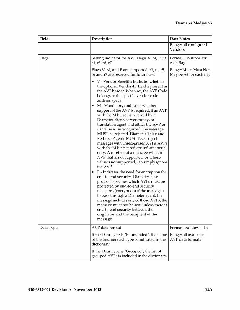
Data NotesDescriptionFieldRange: all configuredVendors
Format: 3 buttons foreach flag
Setting indicator for AVP Flags: V, M, P, r3,r4, r5, r6, r7
Flags
Range: Must, Must Not,May be set for each flag
Flags V, M, and P are supported; r3, r4, r5,r6 and r7 are reserved for future use.
• V - Vendor-Specific; indicates whetherthe optional Vendor-ID field is present inthe AVP header. When set, the AVP Codebelongs to the specific vendor codeaddress space.
• M - Mandatory; indicates whethersupport of the AVP is required. If an AVPwith the M bit set is received by aDiameter client, server, proxy, ortranslation agent and either the AVP orits value is unrecognized, the messageMUST be rejected. Diameter Relay andRedirect Agents MUST NOT rejectmessages with unrecognized AVPs. AVPswith the M bit cleared are informationalonly. A receiver of a message with anAVP that is not supported, or whosevalue is not supported, can simply ignorethe AVP.
• P - Indicates the need for encryption forend-to-end security. Diameter baseprotocol specifies which AVPs must beprotected by end-to-end securitymeasures (encryption) if the message isto pass through a Diameter agent. If amessage includes any of those AVPs, themessage must not be sent unless there isend-to-end security between theoriginator and the reciipient of themessage.
Format: pulldown listAVP data formatData Type
Range: all availableAVP data formats
If the Data Type is "Enumerated", the nameof the Enumerated Type is indicated in thedictionary.
If the Data Type is "Grouped", the list ofgrouped AVPs is included in the dictionary.
349910-6822-001 Revision A, November 2013
Diameter Mediation
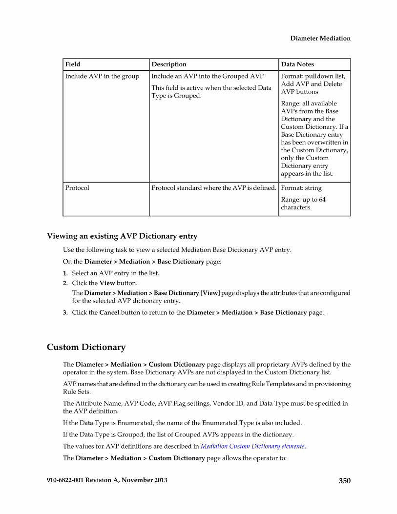
Data NotesDescriptionField
Format: pulldown list,Add AVP and DeleteAVP buttons
Include an AVP into the Grouped AVP
This field is active when the selected DataType is Grouped.
Include AVP in the group
Range: all availableAVPs from the BaseDictionary and theCustom Dictionary. If aBase Dictionary entryhas been overwritten inthe Custom Dictionary,only the CustomDictionary entryappears in the list.
Format: stringProtocol standard where the AVP is defined.Protocol
Range: up to 64characters
Viewing an existing AVP Dictionary entry
Use the following task to view a selected Mediation Base Dictionary AVP entry.
On the Diameter > Mediation > Base Dictionary page:
1. Select an AVP entry in the list.2. Click the View button.
The Diameter > Mediation > Base Dictionary [View] page displays the attributes that are configuredfor the selected AVP dictionary entry.
3. Click the Cancel button to return to the Diameter > Mediation > Base Dictionary page..
Custom Dictionary
The Diameter > Mediation > Custom Dictionary page displays all proprietary AVPs defined by theoperator in the system. Base Dictionary AVPs are not displayed in the Custom Dictionary list.
AVP names that are defined in the dictionary can be used in creating Rule Templates and in provisioningRule Sets.
The Attribute Name, AVP Code, AVP Flag settings, Vendor ID, and Data Type must be specified inthe AVP definition.
If the Data Type is Enumerated, the name of the Enumerated Type is also included.
If the Data Type is Grouped, the list of Grouped AVPs appears in the dictionary.
The values for AVP definitions are described in Mediation Custom Dictionary elements.
The Diameter > Mediation > Custom Dictionary page allows the operator to:
350910-6822-001 Revision A, November 2013
Diameter Mediation
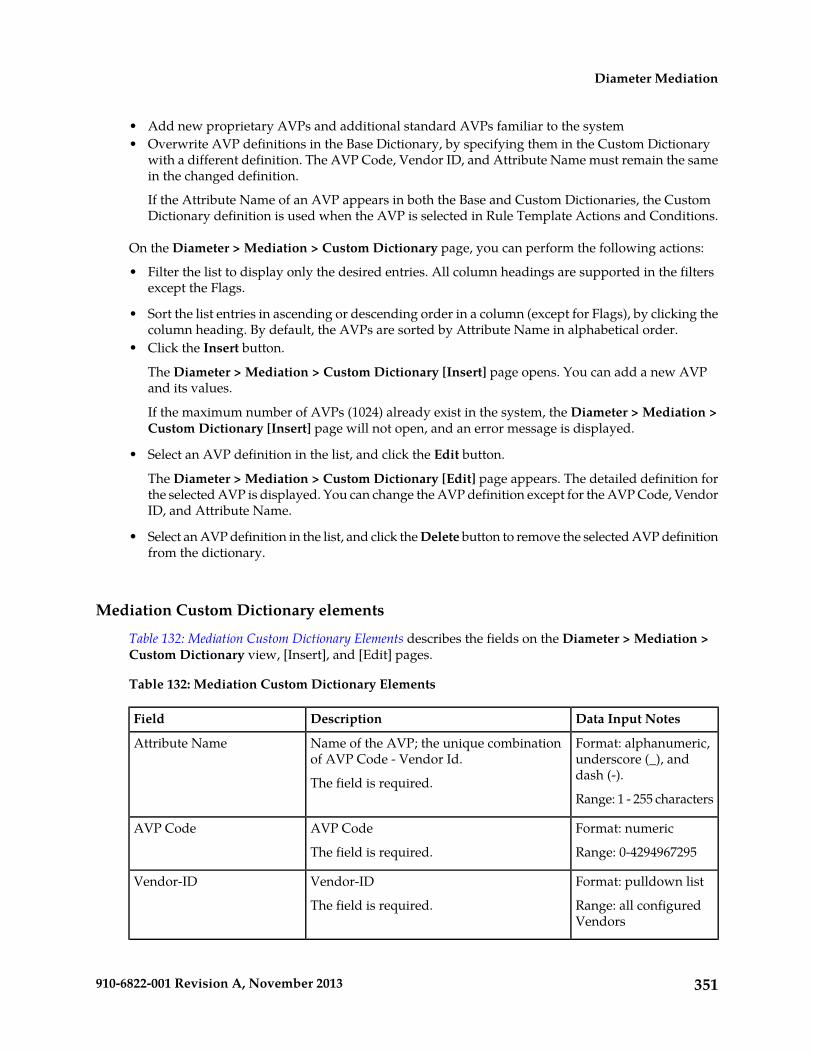
• Add new proprietary AVPs and additional standard AVPs familiar to the system• Overwrite AVP definitions in the Base Dictionary, by specifying them in the Custom Dictionary
with a different definition. The AVP Code, Vendor ID, and Attribute Name must remain the samein the changed definition.
If the Attribute Name of an AVP appears in both the Base and Custom Dictionaries, the CustomDictionary definition is used when the AVP is selected in Rule Template Actions and Conditions.
On the Diameter > Mediation > Custom Dictionary page, you can perform the following actions:
• Filter the list to display only the desired entries. All column headings are supported in the filtersexcept the Flags.
• Sort the list entries in ascending or descending order in a column (except for Flags), by clicking thecolumn heading. By default, the AVPs are sorted by Attribute Name in alphabetical order.
• Click the Insert button.
The Diameter > Mediation > Custom Dictionary [Insert] page opens. You can add a new AVPand its values.
If the maximum number of AVPs (1024) already exist in the system, the Diameter > Mediation >Custom Dictionary [Insert] page will not open, and an error message is displayed.
• Select an AVP definition in the list, and click the Edit button.
The Diameter > Mediation > Custom Dictionary [Edit] page appears. The detailed definition forthe selected AVP is displayed. You can change the AVP definition except for the AVP Code, VendorID, and Attribute Name.
• Select an AVP definition in the list, and click the Delete button to remove the selected AVP definitionfrom the dictionary.
Mediation Custom Dictionary elements
Table 132: Mediation Custom Dictionary Elements describes the fields on the Diameter > Mediation >Custom Dictionary view, [Insert], and [Edit] pages.
Table 132: Mediation Custom Dictionary Elements
Data Input NotesDescriptionField
Format: alphanumeric,underscore (_), anddash (-).
Name of the AVP; the unique combinationof AVP Code - Vendor Id.
The field is required.
Attribute Name
Range: 1 - 255 characters
Format: numericAVP CodeAVP Code
Range: 0-4294967295The field is required.
Format: pulldown listVendor-IDVendor-ID
Range: all configuredVendors
The field is required.
351910-6822-001 Revision A, November 2013
Diameter Mediation
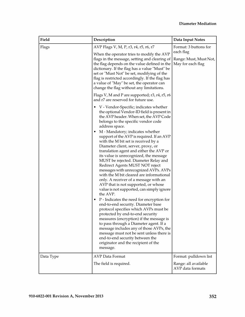
Data Input NotesDescriptionField
Format: 3 buttons foreach flag
AVP Flags V, M, P, r3, r4, r5, r6, r7
When the operator tries to modify the AVPflags in the message, setting and clearing of
Flags
Range: Must, Must Not,May for each flagthe flag depends on the value defined in the
dictionary. If the flag has a value "Must" beset or "Must Not" be set, modifying of theflag is restricted accordingly. If the flag hasa value of "May" be set, the operator canchange the flag without any limitations.
Flags V, M and P are supported; r3, r4, r5, r6and r7 are reserved for future use.
• V - Vendor-Specific; indicates whetherthe optional Vendor-ID field is present inthe AVP header. When set, the AVP Codebelongs to the specific vendor codeaddress space.
• M - Mandatory; indicates whethersupport of the AVP is required. If an AVPwith the M bit set is received by aDiameter client, server, proxy, ortranslation agent and either the AVP orits value is unrecognized, the messageMUST be rejected. Diameter Relay andRedirect Agents MUST NOT rejectmessages with unrecognized AVPs. AVPswith the M bit cleared are informationalonly. A receiver of a message with anAVP that is not supported, or whosevalue is not supported, can simply ignorethe AVP.
• P - Indicates the need for encryption forend-to-end security. Diameter baseprotocol specifies which AVPs must beprotected by end-to-end securitymeasures (encryption) if the message isto pass through a Diameter agent. If amessage includes any of those AVPs, themessage must not be sent unless there isend-to-end security between theoriginator and the recipient of themessage.
Format: pulldown listAVP Data FormatData Type
Range: all availableAVP data formats
The field is required.
352910-6822-001 Revision A, November 2013
Diameter Mediation

Data Input NotesDescriptionField
Format: pulldown list,Add AVP and DeleteAVP buttons
Include an AVP into the Grouped AVP
This field is active when the selected DataType is Grouped.
Include AVP in the group(insert and edit pages only)
Range: all availableAVPs from the BaseTo include another AVP in the Grouped
AVP, click on the Add AVP button. A newrow for AVP selection appears. Dictionary and the
Custom Dictionary. If aBase Dictionary entryTo remove an AVP from the Grouped AVP,
click on the Delete AVP button. has been overwritten inthe Custom Dictionary,only the CustomDictionary entryappears in the list.
Format: stringProtocol standard where the AVP is defined.Protocol
Range: up to 64characters
The field is required.
Adding a new AVP Dictionary entry
Use the following task to add a new AVP Dictionary entry to the Custom Dictionary, or overwrite aBase Dictionary AVP.
The attributes are described in Mediation Custom Dictionary elements.
1. Select Diameter > Mediation > Custom Dictionary.The Diameter > Mediation > Custom Dictionary page appears.
The Diameter > Mediation > Custom Dictionary page will not open if the maximum number ofAVPs (1024) have already been created in the dictionary.
2. Click the Insert button.The Diameter > Mediation > Custom Dictionary [Insert] page opens.
3. Enter the attribute values for the new AVP, or customize a Base Dictionary AVP by changing fieldsexcept the Attribute Name, AVP Code, and Vendor-ID.
4. Click:
• OK to save the changes and return to the Diameter > Mediation > Custom Dictionary page.• Apply to save the changes and remain on the Diameter > Mediation > Custom Dictionary
[Insert] page.• Cancel to return to the Diameter > Mediation > Custom Dictionary page without saving any
changes.
If OK or Apply is clicked and if a Base Dictionary entry is overwritten and the original entry isused by any Rule Templates, the original entry is used until the application is restarted.
353910-6822-001 Revision A, November 2013
Diameter Mediation

Changing an existing AVP Dictionary entry
Use the following task to change an existing Custom Dictionary AVP entry.
Note: Base Dictionary entries cannot be edited directly. To change a Base Dictionary entry, use theAdding a new AVP Dictionary entry procedure to enter a new AVP in the Custom Dictionary that hasthe same Attribute Name, AVP Code, and Protocol as the Base Dictionary entry that you want tochange. Enter different values for the attributes that you want to change.
The fields are described in Mediation Custom Dictionary elements.
1. Select Diameter > Mediation > Custom Dictionary.The Diameter > Mediation > Custom Dictionary page appears.
2. In the list, select the entry to be changed, and click the Edit button.The Diameter > Mediation > Custom Dictionary [Edit]page appears.
3. Change the available attributes as needed .
The Attribute Name, AVP Code, and Protocol cannot be changed.
4. Click:
• OK to save the changes and return to the Diameter > Mediation > Custom Dictionary page.
• Apply to save the changes and remain on the Diameter > Mediation > Custom Dictionary[Edit] page.
Cancel to return to the Diameter > Mediation > Custom Dictionary page without saving anychanges.
If the old version of the AVP is referred to by any Rule Template, the application must be restartedto begin use of the changed AVP. The old version will be used until the restart is done.
Deleting an AVP dictionary entry
Use the following procedure to delete an AVP entry from the Custom Dictionary.
1. Select Diameter > Mediation > Custom Dictionary.
The Diameter > Mediation > Custom Dictionary page appears.
2. Select the Attribute Name of the AVP entry to be deleted.3. Click the Delete button.
A popup window appears to confirm the delete.
4. Click:
• OK to delete the AVP and return to the Diameter > Mediation > Custom Dictionary page.• Cancel to return to theDiameter > Mediation > Custom Dictionary page without deleting the
AVP.
When OK is clicked and any configured Rule Template or Rule Set refers to the AVP that is beingdeleted, the AVP is not deleted and an error message appears.
354910-6822-001 Revision A, November 2013
Diameter Mediation

All-AVP Dictionary
The Diameter > Mediation > All-AVP Dictionary page allows the operator to view all AVP entriesthat are in the Base and Custom Dictionaries. The Base Dictionary entries are black and the CustomDictionary entries are blue. (The term "AVP Dictionary" refers to the combined contents of the Baseand Custom Dictionaries.)
Note: If a Base Dictionary AVP has been overwritten in the Custom Dictionary, only the CustomDictionary entry is shown in the All-AVP Dictionary list.
The list and the entries cannot be changed from this page.
Proprietary and additional standard AVP definitions can be added in the Custom Dictionary. SeeCustom Dictionary.
The AVP definitions in the Base Dictionary can be changed (overwritten) by specifying them in theCustom Dictionary with a different definition. The code, Vendor ID, and attribute name must remainthe same in the changed definition. See Base Dictionary and Custom Dictionary.
On the Diameter > Mediation > All-AVP Dictionary page, you can perform the following actions:
• Filter the list to display only the desired entries.
• Sort the list entries in ascending or descending order in a column, by clicking the column heading(except the flag headings).
• Select an AVP definition in the list, and click the View button.
The Diameter > Mediation > All-AVP Dictionary > [View] page appears. The detailed definitionfor the selected AVP is displayed (the definition cannot be changed on this page). The definitionelements are described in Mediation All-AVP Dictionary elements.
Mediation All-AVP Dictionary elements
Table 133: Mediation All-AVP Dictionary elements describes the fields on the Diameter > Mediation >All-AVP Dictionary pages.
Table 133: Mediation All-AVP Dictionary elements
Data NotesDescriptionField
Format: alphanumeric,underscore (_), anddash (-).
Name of the AVP; the unique combinationof AVP Code - Vendor Id.
Attribute Name
Range: 1 - 255 characters
Format: numericAVP CodeAVP Code
Range: 0-4294967295
Format: pulldown listVendor-IDVendor-ID
355910-6822-001 Revision A, November 2013
Diameter Mediation

Data NotesDescriptionFieldRange: all configuredVendors
Format: 3 buttons foreach flag
AVP Flags V, M, P, r3, r4, r5, r6, r7
Flags V, M, and P are supported; r3, r4, r5,r6 and r7 are reserved for future use.
Flags
Range: Must, Must Not,May for each flag• V - Vendor-Specific; indicates whether
the optional Vendor-ID field is present inthe AVP header. When set, the AVP Codebelongs to the specific vendor codeaddress space.
• M - Mandatory; indicates whethersupport of the AVP is required. If an AVPwith the M bit set is received by aDiameter client, server, proxy, ortranslation agent and either the AVP orits value is unrecognized, the messageMUST be rejected. Diameter Relay andRedirect Agents MUST NOT rejectmessages with unrecognized AVPs. AVPswith the M bit cleared are informationalonly. A receiver of a message with anAVP that is not supported, or whosevalue is not supported, can simply ignorethe AVP.
• P - Indicates the need for encryption forend-to-end security. Diameter baseprotocol specifies which AVPs must beprotected by end-to-end securitymeasures (encryption) if the message isto pass through a Diameter agent. If amessage includes any of those AVPs, themessage must not be sent unless there isend-to-end security between theoriginator and the recipient of themessage.
Format: pulldown listAVP Data FormatData Type
Range: all availableAVP data formats
Format: pulldown list,Add AVP and DeleteAVP buttons
Include an AVP into the Grouped AVP
This field is active when the selected DataType is Grouped.
Include AVP in the group
Range: all availableAVPs from the BaseDictionary and theCustom Dictionary. If a
356910-6822-001 Revision A, November 2013
Diameter Mediation

Data NotesDescriptionFieldBase Dictionary entryhas been overwritten inthe Custom Dictionary,only the CustomDictionary entryappears in the list.
Format: stringProtocol standard where the AVP is defined.Protocol
Range: up to 64characters
Viewing an existing All-AVP Dictionary entry definition
Use the following task to view a selected Mediation All-AVP Dictionary AVP entry definition. (Thedefinition cannot be changed on this page.)
1. Select Diameter > Mediation > All-AVP Dictionary.The Diameter > Mediation > All-AVP Dictionary page appears.
2. Select an AVP entry in the list and click the View button.The Diameter > Mediation > All-AVP Dictionary [View] page displays the attributes that areconfigured for the selected AVP dictionary entry.
3. Click the Cancel button to return to the Diameter > Mediation > All-AVP Dictionary page.
Vendors
The Diameter > Mediation > Vendors page lists the Names and IDs of all Vendors made known tothe system.
Vendors are used in defining new Vendor-specific AVPs in the Custom Dictionary.
On the Diameter > Mediation > Vendors page, you can perform the following actions:
• Filter the list of Vendors to display only the desired Vendors.• Sort the displayed Vendors by ascending or descending Vendor ID or Vendor Name, by clicking
the column heading.• Click the Insert button.
The Diameter > Mediation > Vendors [Insert] page opens. You can add a new Vendor. See Addinga Vendor.
If the maximum number of Vendors (128) already exist in the system, the Diameter > Mediation> Vendors [Insert] page will not open, and an error message is displayed.
• Select a Vendor row in the list, and click the Edit button.
The Diameter > Mediation > Vendors [Edit] page opens. You can edit the Vendor Name for theselected Vendor. See Editing a Vendor Name.
357910-6822-001 Revision A, November 2013
Diameter Mediation

The Diameter > Mediation > Vendors [Edit] page will not open if the selected Vendor is used inany of the AVP definitions in the dictionary.
• Select a Vendor row in the list, and click the Delete button to remove the selected Vendor. SeeDeleting a Vendor.
A Vendor cannot be deleted if it is used in any AVP definitions in the AVP Dictionary.
Mediation Vendors elements
Table 134: Mediation Vendors elements describes the fields on the Diameter > Mediation > VendorsView, Insert, and Edit pages. Data Input Notes apply only to the Insert and Edit pages; the View pageis read-only.
Table 134: Mediation Vendors elements
Data Input NotesDescriptionElement
Format: 32-bit integerA number that identifies theVendor. The number must be
Vendor-ID
Range: 1-4294967295unique within the CustomDictionary.
The field is required.
Format: Character stringName of a Vendor thatimplements a Vendor-SpecificDiameter AVP.
Vendor Name
Range: 1-255 characters
A unique name is required inthis field.
Viewing Vendors
The use of Mediation Vendors is described in Vendors.
To view all configured Mediation Vendors, select Diameter > Mediation > Vendors.
The Diameter > Mediation > Vendors page appears with a list of configured Vendors. The fields aredescribed in Mediation Vendors elements.
Adding a Vendor
The following procedure can be used to configure a new Vendor.
The fields are described in Mediation Vendors elements.
1. Select Diameter > Mediation > Vendors.
The Diameter > Mediation > Vendors page appears.
2. Click Insert.
358910-6822-001 Revision A, November 2013
Diameter Mediation

The Diameter > Mediation > Vendors [Insert] page appears.
If the maximum number of Vendors (128) has already been configured in the system, the Diameter> Mediation > Vendors [Insert] page will not open, and an error message will appear.
3. Enter a unique Vendor Name for the Vendor that is being added.4. Enter a Vendor ID for the Vendor.5. Click:
• OK to save the changes and return to the Diameter > Mediation > Vendors page.• Apply to save the changes and remain on the Diameter > Mediation > Vendors [Insert] page.• Cancel to return to the Diameter > Mediation > Vendors [Insert] page without saving any
changes.
If OK or Apply is clicked and any of the following conditions exist, an error message appears:
• The Vendor Name or Vendor ID contains any characters that are not valid or are out of theallowed range
• The Vendor Name or Vendor ID is empty (not entered)• The Vendor Name is not unique
Editing a Vendor Name
Use this procedure to change a Vendor Name.
The Vendor ID cannot be changed.
The Vendor Name cannot be changed if the Vendor is used in any of the AVP definitions in thedictionary.
The fields are described in Mediation Vendors elements.
1. Select Diameter > Mediation > Vendors.The Diameter > Mediation > Vendors page appears.
2. Select the Vendor Name to be changed.3. Click the Edit button.
The Diameter > Mediation > Vendors [Edit] page appears.
4. Change the Vendor Name of the selected Vendor.5. Click:
• OK to save the changes and return to the Diameter > Mediation > Vendors page• Apply to save the changes and remain on the Diameter > Mediation > Vendors [Edit] page.• Cancel to return to the Diameter > Mediation > Vendors page without saving any changes.
If OK or Apply is clicked and any of the following conditions exist, an error message appears:
• The Vendor Name is not unique• The Vendor Name contains characters that are not valid
359910-6822-001 Revision A, November 2013
Diameter Mediation

Deleting a Vendor
Use the following procedure to delete a Vendor.
A Vendor cannot be deleted if the Vendor is used in any AVP definitions in the dictionary.
1. Select Diameter > Mediation > Vendors.
The Diameter > Mediation > Vendors page appears.
2. Select the row that contains the Vendor to be deleted.3. Click the Delete button.
A popup window appears to confirm the delete.
4. Click:
• OK to delete the Vendor.• Cancel to cancel the delete function and return to the Diameter > Mediation > Vendors page.
If the Vendor is used in any AVP definitions in the dictionary, the Vendor is not deleted and anerror message appears.
Rule Sets
A Rule Set is generated from a Rule Template that was defined on the Diameter > Mediation > RuleTemplates page, when the Rule Template state is changed from Development to Test or Active. TheDiameter > Mediation > Rule Sets GUI folder contains an entry for each generated Rule Set. If noRule Sets have been generated, the Rule Sets folder contains no entries. All rules in a Rule Set arespecific to the Rule Template from which the Rule Set was generated.
Clicking a Rule Sets entry opens the Diameter > Mediation > Rule Sets > {name} GUI page for theRule Set ({name} is the name of the Rule Set).
The Diameter > Mediation > Rule Sets > {name} page displays the following columns:
• Move the rule
A Move the rule column appears at the left and at the right of the rules list when there are rulesthat are allowed to be moved up or down in the list to change the order of rule execution.
Up and Down buttons in the Move the rule columns can be used to move a rule up one positionin the list or down one position in the list each time the button is clicked.
Up and Down buttons appear in the Move the rule columns for a rule or rule group when theorder of the rules is allowed to be changed, with the following restrictions:
• When the Filter function or clicking a Condition column heading is used to sort the columns,the Move the rule columns are not displayed. The Restore Order button can be clicked to returnthe list to its original order.
• If all of the conditions in the rule support Fast Search, then the Move the rule columns are notdisplayed. See Fast Search.
• If there is at least one condition that does not support Fast Search, then the Up and Downbuttons are displayed according to the following rules:
360910-6822-001 Revision A, November 2013
Diameter Mediation

All of the rules that support Fast Search always appear in the list before any rules that donot support Fast Search.
•
• The rows that have exactly the same data in the conditions that support Fast Search form agroup. Rows can be moved only within their group; the Up and Down buttons are enabledand disabled accordingly.
Table 135: Example of Default Ordering of Rules in a Rule Set shows an example of defaultordering of rules.
Table 135: Example of Default Ordering of Rules in a Rule Set
Non fast-search condition 3Fast-search condition 2Fast-search condition 1
-1abc
-12abc
--abc
-1abcd
a11abcd
b1-abcd
a11-
b11-
---
• Conditions
One column appears for each condition that is defined in the Rule Template that generated theRule Set. The columns appear from left to right in the same order that the conditions are definedin the Rule Template for the Rule Set. The heading of each column is the Condition Name. Eachentry in a condition column is the data that was entered in the Right value field of the conditionfor the rule.
Each condition column heading can be clicked to sort the rules by the ascending or descendingalphabetical order of the values in that column. The column contents can be used to filter therules that are displayed in the list.
• Actions
One column heading appears for each Action that is assigned to the conditions in the RuleTemplate for the Rule Set. The columns appear from left to right in the same order that theActions are defined in the Rule Template. The Action columns cannot be sorted by clicking theheading; their contents can be used to filter the rules that are displayed in the list
• Action Attribute sub-columns for each Action
Sub-columns appear for the attributes of each Action. The sub-columns cannot be sorted byclicking the heading; their contents can be used to filter the rules that are displayed in the list.All of the conditions in a Rule Template use the same Actions; the Action attributes can beassigned different values in different rules in the Rule Set.
361910-6822-001 Revision A, November 2013
Diameter Mediation

Each row across the columns is created (inserted) in the list when a rule is provisioned. The rules ona Diameter Rule Sets > {name} page are looked up in the database in the order in which they arelisted on the page. By default, the rules are sorted in the list by condition in the following order:
• First the conditions, in alphabetical order from left to right, that have the Fast Search option enabled• Followed by any conditions, in the order that they were provisioned, that do not have the Fast
Search option enabled.• Though all rules in a Rule Set have the same conditions available, rules can be provisioned with
one or more of the conditions “empty” (with no values), indicating that the condition is alwaysmatched in message processing. The rules with empty conditions are listed after the rules thatcontain values for the same conditions.
The Rule Sets folder entries to view, insert (provision), change, or delete rules in Rule Sets.
When a Rule Set entry is selected in the Rule Sets folder, the Diameter > Mediation > Rule Sets >{name} page opens for the selected Rule Set.
On each Diameter > Mediation > Rule Sets > {name} page, a user can perform the following actions:
• Filter by the column contents, to display only the rules with the desired contents.• If the Move a rule columns are displayed and contian Up and Down buttons, move rules up and
down in the list to change the order of execution of the rules in the Rule Set.• Click Insert to add a new rule.
The Diameter > Mediation > Rule Sets > {name} [Insert] page opens.
The Diameter > Mediation > Rule Sets > {name} [Insert] page will not open if adding a new rulewill cause the allowed maximum number of rules in the Rule Set (250) to be exceeded.
The Diameter > Mediation > Rule Sets > {name} [Insert] page will not open if adding a new rulewill cause the allowed maximum total number of rules in the system (25000) to be exceeded.
Rule Templates without any conditions form a special case, because their provisioned ruleunconditionally matches. The Rule Sets generated from these Rule Templates allow only one ruleto be provisioned.
• Click Delete All Rules to delete all of the rules that have been provisioned for this Rule Set.• Select a rule and click Edit.
The Diameter > Mediation > Rule Sets > {name} [Edit] page opens. You can change the Values ofthe Conditions and Actions for the selected rule.
• Select a rule and click Delete to delete the rule from the Rule Set list.
User-defined Rule Sets
Rule Templates that are defined using the Diameter > Mediation > Rule Templates page generatenew Mediation Rule Sets when the Rule Template is set to the "Test" or "Active" state. These generatedRule Sets appear in the Diameter > Mediation > Rule Sets GUI menu.
If no Mediation Rule Sets have been generated from Rule Templates, rather than being a menu, RuleSets is a page that displays "NO Rule Sets are defined yet".
362910-6822-001 Revision A, November 2013
Diameter Mediation

Adding a user-defined Rule SetIf no Mediation Rule Sets are defined, Mediation > Rule Sets is a page that displays "NO MediationRule Sets are defined yet", and no Mediation Rule Sets are available to be added here. To define aMediation Rule Set, use the Mediation > Rule Templates page.
Rule Sets elements - View page
Table 136: Rule Sets Elements - View Page describes the elements that appear on each Diameter >Mediation > Rule Sets > {name} page.
Table 136: Rule Sets Elements - View Page
Data NotesDescriptionElement
Format: Buttons in two columnsunder the heading
Used to move a rule up or downin the list, to change the order ofexecution of the rules.
Move the rule
Range: Up, DownThe rules are executed in theorder shown in the list, from the One, both, or no buttons appear
in the columns, depending onthe rule definition.top of the list to the bottom of
the list.
The element appears at the leftof and at the right of each rulerow.
Format, Range, and DefaultValue vary depending on the
Each condition name has aseparate column in the list.
All Conditions defined on theRule Template page for this RuleSet Rule Template that was
configured for the Rule Set.
Format, Range, and DefaultValue vary depending on the
Each Action defined for this Ruletask has a separate column in the
All Actions defined on the RuleTemplate page for this Rule Set
Rule Template that wasconfigured for the Rule Set.
list that shows the name of theAction, and one or moresub-columns that show theattributes that were defined forthe Action and the current valuesof the attributes.
If the Parent AVP or AVP isindexed, then the index isdisplayed in the square bracketsafter the AVP attribute name.
If an AVP is looked up in themessage by its value, “AVP”shall contain the value prefixedwith “=” (if it is a constant) or anxl-value prefixed with “=” (if itis an xl-value).
363910-6822-001 Revision A, November 2013
Diameter Mediation

Data NotesDescriptionElementA value can be prefixed with anappropriate indicator of its typeor function (such as =,beginning, end, prefix, or suffix).
Each rule in the Rule Set is a row in the list. The Values assigned to the Conditions and the Valuesassigned to each attribute of the Actions for a rule are shown in the row for that rule.
Rule Sets elements - Insert and Edit Pages
Table 137: Maximum Allowed Rule Sets and Rules indicates the maximum number of Rule Sets and rulesthat are allowed.
Table 137: Maximum Allowed Rule Sets and Rules
ValueDescription
25000Maximum number of provisioned rules in the system
250Maximum number of provisioned rules per Rule Set
Table 138: Rule Sets Elements - Insert and Edit Pages describes the elements that are shown on a Diameter> Mediation > Rule Sets > {name} [Insert] or [Edit] page.
Table 138: Rule Sets Elements - Insert and Edit Pages
Data Input NotesDescriptionElement
Field: This element has two sections: IF and THEN.
Format: Name of the Condition,followed by its Operator
The list of Condition names (if anyConditions were defined for the RuleTemplate).
IF
The name and operator cannot beentered or changed.AND appears between each two
Conditions.
Format: NameThe name of each Action that was definedfor the Rule Template.
THEN
An Action cannot be deleted and anew Action cannot be defined forthe rule.
Value: This element shows the fields for the Condition and Action data Values that can be enteredor changed.
For the [Insert] page, the fields are either empty or show default values.
For the [Edit] page, the fields show the currently defined or default values.
364910-6822-001 Revision A, November 2013
Diameter Mediation

Data Input NotesDescriptionElement
Format: text boxFor each defined Condition in the rule,the data value for the Right value type inthe Condition.
Conditionexpression Rightvalue Range: Varies depending on the
Right value typeIf the Optional check box was checked inthe Rule Template for this Rule Set, the Default: Varies depending on the
Right value typeRight value can be empty (notSee Rule Template elements.provisioned). A red asterisk appears after
each data value that is required (notoptional) in the rule. The Formatting Value Wizard is
available to provision ConditionRight values that are xl-formattedIf the Fixed check box was checked in the
Rule Template for this Rule Set, the Rightvalue cannot be changed in the rules.
values; click [wizard] that appearsafter the data value field.
If the selected Right value type was anEnumerated Type, then the Value columncontains a pulldown list with thecorresponding Enumerated Type values,unless the selected Operator was “exists”,“does not exist”, “is true” or “is false”.
Format: Varies for each type ofattribute
Range: Varies for each type ofattribute
The fields to use to define the data valuesfor Action attributes.
Action fields
See Rule Template elements.
The Formatting Value Wizard isavailable to provision Actionattributes that are xl-formattedvalues; click [wizard] that appearsafter the data value field.
Format: descriptive textThe description that was defined in theRule Template for a Condition or anAction on the Rule Sets page.
Description
Range: 1 to 255 characters string
The description can provide informationsuch as the format to be used (such as textstring or telephone number format) andthe range of values (such as 1 to 255characters).
Adding a Rule to a Rule Set
Use this procedure to define a new rule in a Rule Set. A maximum of 250 rules can be defined in oneRule Set.
365910-6822-001 Revision A, November 2013
Diameter Mediation

There are two sections of a Diameter > Mediation > Rule Sets > {name} [Insert] page: IF (zero, one,or more Conditions) and THEN (an Action). For a list of the Rule Template elements that appear in arule and their definitions, see Rule Template elements.
When a Rule Template is in the "Active" or "Test" state, this Rule Template appears as a Rule Set inthe Diameter > Mediation > Rule Sets menu folder. The order in which rules appear on a Diameter> Mediation > Rule Sets > {name} page determines the order in which the conditions are processed.The Up and Down buttons next to the rules can be used to change the order of processing.
1. Select Diameter > Mediation > Rule Sets > {name}.The selected Diameter > Mediation > Rule Sets > {name} page opens.
2. Click the Insert button.The Diameter > Mediation > Rule Sets > {name} [Insert] page opens.
If the maximum number of rules are already defined for the Rule Set (250) , the Diameter >Mediation > Rule Sets > {name} [Insert] page will not open, and an error message is displayed.
3. Enter the Value for each condition that appears under IF in the Field section for the new rule.4. Enter the Value for each attribute of the Action that appears under THEN in the Field section for
the new rule.5. When the rule definition is complete, click:
• OK to save the new rule and return to the Diameter > Mediation > Rule Sets > {name} page.The rule name appears in the list on the page.
• Apply to save the new rule and remain on the Diameter > Mediation > Rule Sets > {name}[Insert] page for additional changes.
• Cancel to return to the Diameter > Mediation > Rule Sets > {name} page without saving thechanges.
If OK or Apply is clicked and any of the following conditions exist, an error or warning messageappears:
• Any mandatory input fields are empty• Any input Value fields in the Conditions or Actions did not conform to the required syntax
defined by the Right value type or the Action definition• Another rule exists within the Rule Set with the same Values in the Condition section; the rule
Condition already exists in the Rule Set• Adding the new rule would cause the allowed maximum number (250) of rules in a Rule Set
in the system to be exceeded• Adding the new rule would cause the allowed maximum number (250000) of rules in the system
to be exceeded
6. When the Rule Set definition and testing are complete, go to the Diameter Mediation State &Properties page.a) Change the Rule Template State from Test to Active.b) Set the Action Error Handling property, if needed.The state can be changed to Active after the testing is successful, the Rule Set data is provisioned,the Rule Set is associated with a Trigger, and the Rule Set is ready to use in live traffic.
366910-6822-001 Revision A, November 2013
Diameter Mediation

Deleting All Rules from a Rule Set
Use this procedure to delete all rules from a Rule Set.
1. Select Diameter > Mediation > Rule Sets > {name}.
The selected Diameter > Mediation > Rule Sets > {name} page appears.
2. Click Delete All Rules.A popup window appears to confirm the delete.
3. On the popup window, click:
• OK to delete all rules and return to the Diameter > Mediation > Rule Sets > {name} page.• Cancel to cancel the delete operation and return to the Diameter > Mediation > Rule Sets >
{name} page.
Changing a Rule in a Rule Set
Use this procedure to change values for a rule in a Rule Set (for a list of Rule Sets elements and theirdefinitions, see Rule Sets elements - Insert and Edit Pages):
1. In the Diameter > Mediation > Rule Sets folder, select the Rule Set that contains the rule to beedited.
The Diameter > Mediation > Rule Sets > {name} page appears for the selected Rule Set.
2. Select the rule that needs to be changed.3. Click Edit.
The Diameter > Mediation > Rule Sets > {name} [Edit] page appears.
4. Change values for Conditions under IF and Actions under THEN as needed.5. Click:
• OK to save the changes and return to the Diameter > Mediation > Rule Sets > {name} page.• Apply to save the changes and remain on the Diameter > Mediation > Rule Sets > {name}
[Edit] page.• Cancel to return to the Diameter > Mediation > Rule Sets > {name} page without saving any
changes.
Deleting One Rule from a Rule Set
Use this procedure to delete one rule from a Rule Set.
1. Select Diameter > Mediation > Rule Sets > {name}.
The selected Diameter > Mediation > Rule Sets > {name} page appears.
2. Select the row for the rule to be deleted.3. Click Delete.
A popup window appears to confirm the delete.
367910-6822-001 Revision A, November 2013
Diameter Mediation

4. On the popup window, click:
• OK to delete the rule and return to the Diameter > Mediation > Rule Sets > {name} page.• Cancel to cancel the delete operation and return to the Diameter > Mediation > Rule Sets >
{name} page.
368910-6822-001 Revision A, November 2013
Diameter Mediation

Chapter
7DSR Capacity and Congestion Controls
The DSR provides the features and functions forper-connection and per-MP capacity and congestion
Topics:
• Introduction.....370 control. Egress Throttle Groups can monitor Egress• DA-MP Overload Control.....370 Message Rate and Pending Transactions across
multiple DA-MPs in a DSR.• Per-Connection Ingress MPS Control.....372• Remote Congestion Controls.....376• Egress Throttle Groups.....389
369910-6822-001 Revision A, November 2013

Introduction
The DSR provides the following features and functions for capacity and congestion control:
• DA-MP Overload Control• Per-Connection Ingress MPS Control• User Configurable Message Priority• Remote BUSY Congestion• Egress Transport Congestion• Per-Connection Egress Message Throttling• User-Configurable Connection Pending Transaction Limiting• Egress Throttle Groups• Functions associated with Message Priority and Connection Congestion:
• DSR egress Request routing incorporates Request Message Priority and Connection CongestionLevel in its Connection selection criteria.
• The Routing Option Set associated with the ingress Request specifies what action is taken bythe DSR when routing of a Request is abandoned and the last Connection evaluated wascongested.
• The maintenance status for a congested Connection indicates whether the congestion is due toRemote BUSY Congestion, Egress Transport Congestion, or Egress Message Throttling.
The Diameter Transport Function services its per-Connection ingress sockets with per-ConnectionMPS controls that ensure fairness in reading ingress messages for all established Connections.
The Diameter Transport Function services its per-Connection egress queues with controls that ensurefairness in forwarding egress messages to Peers for all established Connections.
Egress Throttle Groups monitor Egress Message Rate, Pending Transactions, or both, for logical groupsof Diameter Connections or Peers, or both, across multiple DA-MPs on a DSR Network Element.
DA-MP Overload Control
DA-MP Overload Control (Message Priority and Color-Based DA-MP Overload Control) provides amechanism for managing internal/local DA-MP congestion detection and control.
The DA-MP Overload Control feature tracks ingress message rate, calculates the amount of traffic thatneeds to be shed based on CPU congestion, and sheds that traffic based on Message Priority, MessageColor, and discard policy.
Message Color is used as a means for differentiating Diameter Connections that are under-utilizedversus those that are over-utilized with respect to ingress traffic - traffic from under-utilized Connectionsis marked "green" by the Per-Connection Ingress MPS Control (PCIMC) feature, while traffic fromover-utilized Connections is marked "yellow". In the event of (Danger of Congestion or of CPUcongestion and based on the specified discard policy, traffic from over-utilized Connections isconsidered for discard before traffic from under-utilized Connections. Traffic discarded by PCIMCdue to capacity exhaustion (per-Connection or shared) is marked "red" and is not considered for anysubsequent processing.
370910-6822-001 Revision A, November 2013
DSR Capacity and Congestion Controls

The following DA-MP Congestion Controls are associated with reducing the traffic processing loadon the DA-MP when congestion is detected:
• Internal Resource Monitoring and Control
The availability of key traffic-sensitive internal software resources (stack queues and buffer pools)is monitored in real-time against their static maximum capacity.
When resource availability drops below engineered thresholds, alarms are generated. When resourceavailability is exhausted, controls are invoked to prevent over-utilization. Resource utilization KPIsand measurements provide real-time and long-term information for making decisions about systemcapacity and growth.
• DA-MP Overload Control
Traffic loads, if allowed to exceed the DA-MP's engineered capacity, will degrade the effectiveperformance of the DA-MP, increase message latency, and can result in message loss. DA-MPOverload Control is responsible for reducing the traffic processing load to insure that the MP meetsits performance specifications. MP Processing Overload Control monitors the Diameter ProcessCPU utilization of the Diameter Process.
Limitations
• DA-MP Overload Control is limited to local MP congestion management and does not addressremote Diameter node congestion management.
• Automatic recovery from persistent MP or egress Connection congestion is not supported. Manualintervention is required.
Diameter Configuration for DA-MP Overload Control
The following Diameter Configuration components are used for DA-MP Overload Control:
• MP Profiles
A DA-MP Profile is assigned to each DA-MP in the system, using the Diameter > DA-MPs > ProfileAssignments GUI page.
The assigned DA-MP Profile indicates the Engineered Maximum MPS for the DA-MP and theMessage Rate Alarm Set and Clear Thresholds. These engineering-configured MP Profiles valuesshown on the Diameter > DA-MPs > MP Profiles GUI page vary depending on the type of bladeor Rack Mount Server used for the DA-MP.
The following elements can be user-configured on the Diameter > DA-MPs > MP Profiles GUIpage for use by the DA-MP Overload Control feature:
• Congestion Level 1 Discard Percentage - The percent below the DA-MP Engineered IngressMPS that DA-MP Overload Control will police the total DA-MP ingress MPS to when the DA-MPis in Congestion Level 1.
• Congestion Level 2 Discard Percentage - The percent below the DA-MP Engineered IngressMPS that DA-MP Overload Control will police the total DA-MP ingress MPS to when the DA-MPis in Congestion Level 2.
• Congestion Level 3 Discard Percentage - The percent below the DA-MP Engineered IngressMPS that DA-MP Overload Control will police the total DA-MP ingress MPS to when the DA-MPis in Congestion Level 3.
• Congestion Discard Policy - The order of Message Priority and Color-based traffic segments toconsider when determining discard candidates for the application of treatment during DA-MP
371910-6822-001 Revision A, November 2013
DSR Capacity and Congestion Controls

Congestion processing. The following order is considered: Color within Priority, Priority withinColor, and Priority Only.
• Danger of Congestion Discard Percentage - The percent of total DA-MP ingress MPS above theDA-MP Engineered Ingress MPS that DA-MP Overload Control will discard when the DA-MPis in danger of congestion,
• Danger of Congestion Discard Policy - The order of Message Priority and Color-based trafficsegments to consider when determining discard candidates for the application of treatmentduring DA-MP Danger of Congestion (DOC) processing. The following order is considered:Color within Priority, Priority within Color, and Priority Only.
• Routing Option Sets
A Routing Option Set is a set of user-configurable routing options assigned to an ingress Diametertransaction. A Routing Option Set can be assigned to Peer Nodes and Diameter Application IDs.
DA-MP Overload Control uses the following options:
• Resource Exhausted Action• Resource Exhausted Result-Code Value• Resource Exhausted Vendor-ID Value• Resource Exhausted Error-Message Value
Per-Connection Ingress MPS Control
The Per-Connection Ingress MPS Control (PCIMC) feature limits to a configurable level theper-Connection ingress message rate of each DSR Connection. Correctly configured message ratecontrols ensure that a single Connection cannot use the majority of the resources. (No limiting is doneby PCIMC for the egress message rate.)
The Per-Connection Ingress MPS Control feature:
• Is always available in the system• Applies to per-Connection MPS control for Connections that are statically assigned to MP servers
through configuration and do not move from one MP to another• Is applied in the Diameter Transport Function, which is used by all DSR Applications
Capacity management for this feature can be logically separated into:
• Management of the ability of the MP server to process ingress Diameter messages - how the MPserver's resources are distributed to configured Connections
• Management of the ability of a given Connection to process ingress Diameter messages - how eachConnection behaves given its configured reserved and maximum ingress MPS settings
Per Connection Capacity Management
Per-Connection Ingress MPS Control allocates a DA-MP's ingress message processing capacity amongthe Diameter Peer Connections that it hosts. Each Peer Connection is allocated, throughuser-configuration, a Reserved Ingress MPS message processing capacity and a Maximum IngressMPS message processing capacity.
372910-6822-001 Revision A, November 2013
DSR Capacity and Congestion Controls

The Reserved capacity for a Connection is available for exclusive use by the Connection. The capacitybetween a Connection's Reserved and Maximum capacity is shared with other Connections hostedby the DA-MP.
The DA-MP reads messages arriving from a Peer Connection and attempts to process them as longas Reserved or shared ingress message capacity is available for the Connection. When no Reserved orshared ingress message capacity is available for a Connection, the DA-MP enforces a short discardperiod, during which time all ingress messages are read from the Connection and discarded withoutgeneration of any response to the Peer.
Per Connection Ingress Message Coloring
In addition to enforcing ingress message rate limits on a per Connection basis, Per-Connection IngressMPS Control colors ingress messages based on the Reserved and average ingress message rates.Message color can be used at other traffic shedding points in the DSR, such as DA-MP Overload Control.
Traffic from under-utilized Connections is marked "green" by Per-Connection Ingress Message Controls,while traffic from over-utilized Connections is marked "yellow". Traffic discarded by PCIMC due tocapacity exhaustion (per-Connection or shared) is marked "red" and is not considered for anysubsequent processing.
The following items describe the numbered items in Figure 18: Per Connection Message Coloring:
• When the Connection's average ingress MPS rate is equal to or below its configured ReservedIngress MPS, all messages processed by the Connection are colored green.
• When the Connection's average ingress MPS rate is above its configured Reserved Ingress MPS,all messages processed by the Connection are colored yellow.
Note: If the Connection's Reserved Ingress MPS is 0, all the messages processed by the Connectionare colored yellow.
Figure 18: Per Connection Message Coloring
Per MP Server Capacity Management
Tekelec-engineered MPS rates and thresholds are used to manage ingress message MPS as it relatesto the MP server as a whole.
A DA-MP has two Tekelec-configured ingress message rate capacity limits:
• Engineered Ingress MPS - Maximum ingress message rate that a DA-MP will support withoutoverload.
This value provides a limit to the total Reserved Ingress MPS of all Diameter Connections assignedto the DA-MP. The value is displayed on the Diameter > Configuration > DA-MPs > MP ProfilesGUI page for the MP Profile assigned to the DA-MP.
373910-6822-001 Revision A, November 2013
DSR Capacity and Congestion Controls

• MP Engineered Maximum Ingress MPS - A Tekelec-configurable ingress MPS limit that dictatesthe maximum rate at which the DA-MP will attempt to process messages from all DiameterConnections.
This value may be greater than the MP Engineered Ingress MPS.
The DA MP monitors its MPS rate and limits the rate to an MP Engineered Ingress MPS value. If theMP Engineered Ingress MPS rate is exceeded, overload can occur and ingress messages are discarded(due to MP Ingress MPS Limiting and MP Congestion Controls).
Diameter Configuration for Per Connection Ingress MPS Control
Each Diameter Connection is associated with a Capacity Configuration Set that includes the followingconfigurable elements:
• Reserved Ingress MPS - Defines the capacity reserved exclusively for the Connection and notavailable for use by other Connections
The Reserved Ingress MPS cannot exceed the configured Maximum Ingress MPS for a givenConnection. A Connection can be configured with a zero Reserved Ingress MPS value; suchConnections will not reserve message processing capacity.
The Reserved Ingress MPS for a Connection cannot be used by any other Connection, regardlessof the load offered to other Connections.
If the Reserved Ingress MPS Capacity is set to a non-zero value, that value times the number ofConnections using that Capacity Configuration Set on a given MP server must not be allowed toexceed the MP Maximum Reserved Ingress MPS (which is equal to the MP Engineered IngressMPS - the highest MPS rate at which the MP server can process ingress Diameter messages).
• Maximum Ingress MPS - Defines the maximum rate in ingress Diameter messages per second thatthe Connection is allowed to process
The Maximum Ingress MPS must be greater than or equal to the Reserved Ingress MPS. Anydifference between the Maximum Ingress MPS and the Reserved Ingress MPS represents MP serverresources that are shared among Connections that are using the same Capacity Configuration Set.
The configured Maximum Ingress MPS of a Connection cannot exceed the Engineered Ingress MPSof the Connection (the ingress MPS that a Connection can process at a sustained rate without errors).If the Connection has Reserved Ingress MPS, the configured Maximum Ingress MPS must be greaterthan or equal to the Reserved Ingress MPS. All Connections must have a non-zero configuredMaximum Ingress MPS; otherwise they would not be allowed to process traffic at all. (The MaximumIngress MPS value in the Default Capacity Configuration Set is non-zero.)
The sum of the Maximum Ingress MPS configured for all Connections on the MP server can exceedthe MP Engineered Ingress MPS - the highest MPS rate at which the MP server can process ingressDiameter messages.
• Ingress MPS Minor Alarm Threshold - Defines the percent of the Connection's Maximum IngressMPS at which a Minor alarm is triggered
The Ingress MPS Minor Alarm Threshold value must be less than the Ingress MPS Major AlarmThreshold value
• Ingress MPS Major Alarm Threshold - Defines the percent of the Connection's Maximum IngressMPS at which a Major alarm is triggered.
374910-6822-001 Revision A, November 2013
DSR Capacity and Congestion Controls

The Ingress MPS Major Alarm Threshold must be greater than the Ingress MPS Minor AlarmThreshold.
• Reserved Ingress MPS Abatement Time - Defines the minimum time (in ms) that a Connection'singress message rate must remain less than or equal to Reserved Ingress MPS, after exceedingReserved Ingress MPS, in order to revert the ingress traffic color from Yellow to Green.
A Default Capacity Configuration Set is provided; additional Capacity Configuration Sets can beconfigured. The Default Capacity Configuration Set is used for a Connection if no other CapacityConfiguration Set is assigned to the Connection. The elements of the Default Capacity ConfigurationSet have the following default values:
• Reserved Ingress MPS - zero MPS• Maximum Ingress MPS - value equal to the Engineered Ingress MPS for the Connection• Ingress MPS Minor Alarm Threshold - 50% of the configured Maximum Ingress MPS• Ingress MPS Major Alarm Threshold - 80% of the configured Maximum Ingress MPS• Reserved Ingress MPS Abatement Time - 2000 ms
Maintenance and Monitoring for Per Connection Ingress MPS Control
The Per Connection Ingress MPS Control feature provides the following maintenance and monitoringinformation:
• Alarms and measurements to assist the network operator to detect and avoid possible capacityissues related to messaging rates
• The ability to view the average ingress Diameter MPS for each Connection
The Per Connection Ingress MPS Control feature uses the following GUI information:
• The Diameter > Configuration > Connections GUI page specifies which Capacity ConfigurationSet the Connection uses.
• The Diameter > Configuration > Configuration Sets > Capacity Configuration Sets GUI pagesprovide elements for configuring Capacity Configuration Sets.
• The Diameter > Maintenance > Connections GUI page reports KPI 10500 for average ingress MPSfor each Diameter Connection (Ingress Msgs Per Second).
For each Connection, the MP server maintains the average number of ingress Diameter messagesper second read from the socket. This is the rate at which ingress Diameter messages are read fromthe socket, not the rate at which ingress Diameter messages arrive at the socket. There is no efficientmeans to know the rate at which messages actually arrive.
The average ingress message rate is a running average, smoothed over approximately 30 seconds.This provides a good picture of the level of ingress messages being read by each Connection whileavoiding erratic readings caused by short duration spikes in the rate.
Connection Alarm
The Per Connection Ingress MPS Control feature provides a Connection alarm with two severities toalert the network operator when the average ingress MPS rate goes above the configured thresholdsfor percentage of the configured maximum ingress MPS for the Connection.
The Connection Ingress MPS Alarm is a per Connection alarm that can be configured in a Connection'sCapacity Configuration Set to trigger at a Minor and Major capacity threshold.
The Minor alarm is asserted when the 30-second average MPS rate exceeds the configured IngressMPS Minor Alarm Threshold value for the Connection. The Minor alarm is cleared when the 30-second
375910-6822-001 Revision A, November 2013
DSR Capacity and Congestion Controls

average MPS rate falls 5% below the Ingress MPS Minor Alarm Threshold value configured for theConnection.
The Major alarm is asserted when the 30-second average MPS rate exceeds the Ingress MPS MajorAlarm Threshold value configured for the Connection. The Major alarm is converted to a Minor alarmwhen the 30-second average MPS rate falls 5% below the Ingress MPS Major Alarm Threshold valueconfigured for the Connection.
An alarm cannot be abated until an abatement time delay has expired. For example, if a Minor alarmis asserted, the alarm cannot be cleared until the abatement time delay has expired and the averageingress MPS for the Connection is 5% below the Minor alarm assert percentage. The abatement timedelay is 15 seconds.
The alarm abatement time delay affects only clearing of alarms, not asserting of alarms. Therefore, itis possible to transition rapidly from a Minor alarm to a Major alarm.
Limitations
• PCIMC relies on a configured relationship between a Connection and the MP server that will hostthe Connection.
• PCIMC does not prevent the total Reserved Ingress MPS of all Connections hosted by a DA MPfrom exceeding the MP Maximum Reserved MPS capacity when the MP Maximum Reserved MPScapacity is reduced after Connections are already configured with non-zero Reserved Ingress MPS.
Remote Congestion Controls
The following features provide remote congestion controls in the DSR:
• Remote BUSY Congestion - addresses Remote Congestion detection
The DSR Remote BUSY Congestion feature calls for the server to send a "DIAMETER_TOO_BUSY"Answer, which is can be used by the clients to stop sending traffic for some duration. The featureaddresses Remote Congestion detection and the steps to be taken to alleviate the situation.
• Egress Transport Congestion - supports use of transport congestion status
The Egress Transport Congestion feature uses Congestion Levels to manage the egress messagetraffic flow on a Diameter Peer Connection when the Connection's TCP/SCTP send buffer isexhausted, as indicated by the TCP/SCTP socket being "blocked". The socket is blocked when theDiameter Transport Function attempts to write new data to the TCP/SCTP socket fail due toinsufficient send buffer space. When a Diameter Connection socket becomes blocked, the DiameterTransport Function sets the Egress Transport Congestion Level to CL-4 and discards any receivedRequest or Answer messages.
• Per-Connection Egress Message Throttling - targets congestion avoidance
The Per Connection Egress Message Throttling feature targets congestion avoidance by throttlingthe volume of Diameter traffic being sent over a Connection when the traffic exceeds the configuredmaximum egress message rate of the Connection.
• User-Configurable Connection Pending Transaction Limiting - provides a pending transactionlimit for each DSR Peer Connection
376910-6822-001 Revision A, November 2013
DSR Capacity and Congestion Controls

User-Configurable Connection Pending Transaction Limiting (UC-CPTL) provides a configurablepending transaction limit for each DSR Peer Connection, to customize the distribution of theavailable Pending Transaction Records on a DA-MP based on the varying deployment requirements.The limit can be configured independently for each DA-MP in the DSR.
Routing Based on Congestion Level
Features such as Remote BUSY Congestion, Egress Transport Congestion, and Per Connection EgressThrottling Control are used by the DSR to control the flow of egress traffic by setting a feature-specificCongestion Level for a Diameter Connection. Certain Requests can be prioritized over others, usingthe User Configurable Message Priority feature.
The Connection Priority Level (CPL) is an overall Congestion Level for the Connection that is basedupon the highest Congestion Level of the various egress traffic control features. The CPL is used bythe Diameter Routing Function when making egress message routing decisions based on the Priorityprovided by the User Configurable Message Priority feature. No message can be forwarded to aDiameter Connection that has a Priority level less than the CPL for that Connection
The DSR supports up to five Congestion Levels (CL-0 to CL-4), with CL-0 indicating no congestion toCL-4 indicating that the Connection is blocked. The intermediate Congestion Levels CL-1, CL-2, andCL-3 indicate the increasing severity of congestion.
Each feature has a Congestion Level range, as follows:
• Remote BUSY Congestion Levels: CL-0. CL-1, CL-2, and CL-3• Egress Transport Congestion Levels: CL-0. CL-1, CL-2, CL03, and CL-4• Per Connection Egress Message Throttling Congestion Levels: CL-0. CL-1, CL-2, and CL-3
The CPL value for a Connection (CONN-CPL) is based on the maximum Congestion Level of thefeatures.
DSR egress Request routing and Answer forwarding functions use the Connection Congestion Levelin conjunction with the Message Priority to determine how Requests and Answers must be handledover an egress Connection. Message Priority and Connection Congestion Level in the Connectionselection criteria are used to avoid sending messages of Priority x and lower to Connections currentlyat Congestion Level x+1.
All Answers are assigned a Message Priority of 3 by the DSR, while Requests can be assigned MessagePriorities 0 through 2. Messages with a Priority greater than or equal to the Congestion Level areallowed, while messages with lower Priorities are not delivered on this Connection. This arrangementensures that Answers have the highest Priority and are always routed unless a Connection becomesblocked, and depending upon the level of congestion some or all of the Requests may be allowed.Table 139: CLs, CPLs, and Message Treatment summarizes this behavior.
Table 139: CLs, CPLs, and Message Treatment
CommentMessage PrioritiesNot Allowed
Message PrioritiesAllowed
ConnectionCL/CPL Value
Requests nor Answers can besent on the Connection
AllNoneCL-4 /4
Allow only Answers to be senton the Connection
0,1,23CL-3/3
377910-6822-001 Revision A, November 2013
DSR Capacity and Congestion Controls

CommentMessage PrioritiesNot Allowed
Message PrioritiesAllowed
ConnectionCL/CPL Value
Allow only Answers and Pri=2Requests to be sent on theConnection
0,13, 2CL-2/2
Allow only Answers and Pri=2,1Requests to be sent on theConnection
03, 2, 1CL-1/1
All Requests and Answers canbe sent on the Connection
NoneAllCL-0/0
Congestion Levels can be set by multiple features. For example, a particular Connection may havereceived a DIAMETER_TOO_BUSY for a Priority 1 Request (resulting in CL-2 congestion), and whileabating may have experienced transport congestion (CL-4). Therefore, the DSR uses the concept ofConnection Priority Level (CPL) to consider the Congestion Levels reported by all the features whilemaking routing decisions.
The CPL value is a function of Operational Status and the Congestion Levels reported by the RemoteBUSY Congestion, Egress Transport Congestion, and Per Connection Egress Message Throttlingfeatures. Table 140: Mapping Congestion Levels to CPL Values summarizes this behavior.
• The CPL Value for a Connection is based on the worst-case (highest) value:
CPL Value of a Connection = Max (X1, X2, X3, X4)
• This composite CPL value is then used by the Diameter Routing Function as shown in Table 139:CLs, CPLs, and Message Treatment.
Table 140: Mapping Congestion Levels to CPL Values
CPL ValueValueAttribute
0 3 99Available DegradedUnavailable
X1: Diameter Connection Operational Status
0-3CL-0 through CL-3X2: Diameter Connection Remote BUSY Congestion
0-4CL-0 through CL-4X3: Diameter Connection Egress TransportCongestion
0-3CL-0 through CL -3X4: Diameter Connection Egress Message Throttling
Capacity and Ranges
Table 141: Remote BUSY and EMR Capacity Ranges specifies the capacity and ranges for Remote BUSYand Egress Message Rate.
378910-6822-001 Revision A, November 2013
DSR Capacity and Congestion Controls

Table 141: Remote BUSY and EMR Capacity Ranges
DescriptionMaximumItem
Remote BUSY processing on up to 1000simultaneous Diameter connections on a singleG6 DA-MP
1000Remote BUSY processing
Remote BUSY processing on up to 2000simultaneous Diameter connections on a singleG7 DA-MP
2000Remote BUSY processing
Remote BUSY processing on up to 1000simultaneous Diameter connections on a singleG8 DA-MP
1000Remote BUSY processing
Egress Transport Congestion processing on up to1000 simultaneous Diameter connections on asingle G6 DA-MP
1000Egress Transport Congestionprocessing
Egress Transport Congestion processing on up to2000 simultaneous Diameter connections on asingle G7 DA-MP
2000Egress Transport Congestionprocessing
Egress Transport Congestion processing on up to1000 simultaneous Diameter connections on asingle G8 DA-MP
1000Egress Transport Congestionprocessing
Egress Message Throttling on up to 500simultaneous Diameter connections on a singleG6 DA-MP
500Egress Message Throttling
Egress Message Throttling on up to 500simultaneous Diameter connections on a singleG7 DA
500Egress Message Throttling
Egress Message Throttling on up to 500simultaneous Diameter connections on a singleG8 DA
500Egress Message Throttling
Up to 50 in a DSR50Egress Message ThrottlingConfiguration Sets
User Configurable Message Priority
User Configurable Message Priority provides the following functions to set the Priority of messageshandled by the DSR and to use that Priority to as input into decisions for load shedding, messagethrottling, and egress Connection selection:
• A method to assign Message Priorities to incoming Diameter Requests.
The Priorities assigned are based on the combination of Application-Id and Command-Code, andthe Connection upon which the Request arrives. A combination of Application-Id, Command-Code,and associated Priority is called a Message Priority Rule.
• Association of a Message Priority Configuration Set with a Connection.
379910-6822-001 Revision A, November 2013
DSR Capacity and Congestion Controls
• Association of a Message Priority Configuration Set with a Peer Node.• Definition of a Message Priority in a Peer Routing Rule.• A method for Request messages arriving at the DSR to be marked with a Message Priority.• A method for the Message Priority determined by the first DSR to handle a Request to be
communicated to any other DSR that also handles the Request.
Message Priority will be determined based in part on the Connection on which the Request arrivesat the first DSR to handle the Request. A second DSR to handle the Request is not able to establishthe Priority based on the original ingress Connection.
• A method for exception routing and load shedding that allows the Remote BUSY Congestionfeature to use the Message Priority when determining which messages are exception-routed orshed.
• A method for exception routing and load shedding that allows the Egress Transport Congestionfeature to use the Message Priority when determining which messages are exception-routed orshed.
• A method for the message throttling that allows the Per Connection Egress Message Throttlingfeature to use the Message Priority when determining which message are exception routed or shed.
Request messages can be assigned a Message Priority value of 0, 1, or 2 (lowest to highest Priority).
Answer messages are always assigned a Message Priority value of 3 (the highest Priority).
Messages that are given a higher Priority have a lower probability of being dropped as part of sheddingor throttling logic, but having a higher Priority does not imply that the message is routed before amessage with a lower Priority. Having a higher Priority does not guarantee that a messages will neverbe dropped as a result of shedding of messages due to congestion or resource exhaustion. The arrivalpattern of the Requests has an impact on which messages are shed.
Message Priority can be assigned to ingress messages as they enter the DSR, based on:
• The Connection on which a message arrives• The Peer Node from which a message is sent• A Peer Routing Rule
A configured Message Priority Configuration Set can be assigned to a Connection or to a Peer Node
A Message Priority Configuration Set is configured with one or more Message Priority Rules thatspecify Application Ids, Command Codes, and the Message Priority that is assigned to Requestmessages that enter a DSR on a Connection that has been assigned the Message Priority ConfigurationSet.
Message Priority is assigned to ingress Request messages based on message content using the strongestmatching entry in the Configuration Set:
• Application-ID + Command-Code combination• Application-ID• All Request messages (Application Id and Command Code values are *)
In a network where Diameter messages traverse multiple DSRs, Request Message Priority may needto be assigned on one DSR and used by any and all DSRs in the routing path.
Diameter embeds Priority in all Requests that it handles. The method used for embedding Priority inegress Requests is transparent to non-DSR Diameter nodes.
380910-6822-001 Revision A, November 2013
DSR Capacity and Congestion Controls

DSR egress Request routing and Answer forwarding will use Message Priority and ConnectionCongestion Level in its Connection selection criteria to avoid sending Priority x messages to Connectionscurrently at Congestion-Level x+1.
Diameter Configuration for User Configurable Message Priority
The User Configurable Message Priority feature provides the ability to define Message PriorityConfiguration Sets (MPCS). Each MPCS contains the following information:
• MPCS Name - The Name is used when associating the Configuration Set with a Connection orPeer Node
• Message Priority Rules - Sets of Application-ID, Command-Code, and Priority
• Application-ID - The Diameter Application-ID. The Application-Id can be an asterisk (*)indicating that all Application-Ids match this Message Priority Rule
• Command-Code - The Diameter Command-Code. The Command-Code can be an asterisk (*)indicating that all Command-Codes within the specified application match this Message PriorityRule
If multiple Command-Codes with the same Application-Id are to get the same Message Priority,then there must be a separate Message Priority Rule combination for each Command-Code.
• Priority - The Priority applied to all Request messages that match the Application-Id andCommand-Code combination
The Application Id and Command Code must be configured in Diameter Configuration before theycan be used to configure a Message Priority Rule.
A Default Message Priority Configuration Set is provided that contains one Message Priority Rule;the Message Priority Rule is set to accept all Application Ids and all Command Codes (values are *)and has Message Priority set to 0 . The Default Message Priority Configuration Set can be assignedand used if no other Message Priority Configuration Set is assigned to the Connection or the PeerNode (it can be edited if needed).
A total of 20 Message Priority Configuration Sets can be configured per DSR NE. Each Message PriorityConfiguration Set supports up to 50 Message Priority Rules.
A Connection or Peer can be configured with either a MPCS or to get Message Priority from the ingressRequest. If it is configured to get Message Priority from the ingress Request, then it is not possible toconfigure a MPCS for the Connection or Peer.
In Peer Routing Rules, Message Priority valid values are 'No Change', 0, 1 and 2. 0 is the lowest priority.The Message Priority value is applied to the message only when the Peer Routing Rule Action valueis set to Route to Peer.
The following Message Priority treatment configuration options can be selected:
• None (default)• Apply a MPCS (by selecting from a list of configured MPCSs)• Read from message - Used to indicate that the Priority should be taken from the ingress message.
This is used for DSR-to-DSR Connections as a way of conveying Message Priority
This option does not apply to Peer Routing Rules, which have the options None (default) andApply an MPCS.
381910-6822-001 Revision A, November 2013
DSR Capacity and Congestion Controls

Table 142: Message Priority Treatment Methods indicates how DSR determines which method is used. Ifthe Request does not match a rule in the selected Message Priority Configuration Set, then the Requestis assigned a Priority value of zero ("0").
Table 142: Message Priority Treatment Methods
How Priority is Set for IngressRequests on Connection
Message Priority ConfigurationSet Peer Node (for Connection)Setting
Message Priority ConfigurationSet Connection Setting
Use DSR NENot SetNot Set
Use MPCS X to assign Priorityto Ingress Requests
MPCS XNot Set
Extract Priority from IngressRequests
Get Priority from IngressRequests
Not Set
Use MPCS Y to assign Priorityto Ingress Requests
(Don't Care)MPCS Y
Extract Priority from IngressRequests
(Don't Care)Get Priority from IngressRequests
Remote BUSY Congestion
The Remote BUSY Congestion feature can be used per Connection to reduce the amount of messagetraffic sent to a Diameter Connection when an adjacent Diameter Peer Node is unable to processmessages as fast as they are sent to it on the Connection.
Note: The User Configured Message Priority feature is a prerequisite for the Remote BUSY Congestionfeature.
A Connection is considered congested or BUSY if the following conditions exist:
• An Answer message containing 'Diameter_TOO_BUSY' Result Code is received on the Connection• The Answer message was originated by the Peer Node (the Origin-Host of the Answer message is
the same as the Connection's Peer FQDN.
The DSR sets the status 'BUSY' only for the Connection of a Peer on which 'DIAMETER TOO BUSY'is received. The other Connections between the DSR and the Peer may or may not be BUSY.
Remote BUSY Congestion applies only to adjacent nodes. If the node which initiated theDIAMETER_TOO_BUSY, as determined by the Origin-Host AVP value, is not a DSR Peer Node, thenthe DIAMETER_TOO_BUSY will be ignored.
Message traffic reduction is managed through the use of 4 Remote BUSY Congestion Levels: CL-0.CL-1, CL-2, and CL-3, where CL-0 indicates "no congestion" and CL-3 is the highest level of congestion.
A Remote BUSY Congestion Level for a Connection is determined from the Priority of the egresstransactions rejected by a "DIAMETER_TOO_BUSY" response. When a transaction of Priority "X" isrejected by a "DIAMETER_TOO_BUSY" on a Connection whose Remote BUSY Congestion Level is Xor smaller, then the Remote BUSY Congestion of the Connection is set to a value that prevents theDiameter Routing Function from sending subsequent transactions of the same or lower Priority thanthe rejected transaction (in this case, the Remote BUSY Congestion Level is set to X+1). For example,if a "DIAMETER_TOO_BUSY" response is received for a Priority 1 transaction, then the Remote BUSY
382910-6822-001 Revision A, November 2013
DSR Capacity and Congestion Controls

Congestion Level will be set to CL-2 to prevent subsequent transactions of Priority 1 and lower frombeing forwarded on the Connection.
Whenever the Remote BUSY Congestion Level is increased, Remote BUSY Congestion abatement isre-started, using the configured Remote Busy Abatement Timeout value. When the Remote BusyAbatement Timeout expires, the Congestion Level is decremented by 1, allowing transactions withthe next lower Priority to be forwarded on the Connection; the Remote Busy Abatement Timeout isrestarted. This process continues until the Congestion Level of the Connection drops back to CL-0.
Whenever the Remote BUSY Congestion Level is increased, Remote BUSY Congestion abatement isre-started, by starting the Remote BUSY Congestion Abatement Timer. When the Remote BusyAbatement Timeout expires, the Congestion Level is decremented by 1, thus allowing transactionswith the next lower Priority to be forwarded on the Connection; and the Remote Busy AbatementTimeout is restarted. This process continues until the transactions of the Connection drop back toCL-0.
Because Remote BUSY Congestion is detected by inspecting the Result-Code AVP embedded in anAnswer response, detection is performed by the Diameter Routing Function.
Except for Remote BUSY Congestion detection, the Diameter Transport Function is responsible forhandling all of the tasks associated with Remote BUSY Congestion, such as:
• Managing the Remote BUSY Congestion Level• Managing Remote BUSY abatement• Updating the Connection Priority Level (CPL) for the Connection• Keeping OAM informed of the Remote BUSY Congestion status
When the Diameter Routing Function determines that the Remote BUSY Congestion Level needs tobe increased, it notifies the Diameter Transport Function instance that is currently controlling theDiameter Connection.
Because multiple Diameter Routing Function instances can be simultaneously forwarding transactionsto the same Diameter Connection and detecting Remote BUSY Congestion, an internal procedureminimizes the number of simultaneous the Diameter Routing Function-to-Diameter Transport Functiondetection notifications that are associated with any single Diameter Connection.
The Connection Congestion Levels CL-0, CL-1, CL-2, CL-3 and CL-4 are mapped to Connection PriorityLevel (CPL) values 0, 1, 2, 3, 4 respectively.
Diameter Configuration for Remote BUSY Congestion
The Remote BUSY Congestion feature is configured using the following elements on the Diameter >Configuration > Connections GUI page:
• Remote Busy Usage: Enabled, Disabled• Remote Busy Abatement Timeout - time period (in seconds) that a Connection will be considered
BUSY from the last time a DIAMETER_TOO_BUSY response was rec
The configuration elements cannot be modified when the Connection is in service (Connection AdminState=Enabled).
The Remote BUSY Congestion feature can be enabled and disabled for each configured DiameterConnection.
383910-6822-001 Revision A, November 2013
DSR Capacity and Congestion Controls

Egress Transport Congestion
The Egress Transport Congestion feature manages the egress message traffic flow on a Diameter PeerConnection when the Connection's TCP/SCTP send buffer is exhausted, as indicated by the TCP/SCTPsocket being "blocked" (the Diameter Transport Function attempts to write new data to the TCP/SCTPsocket fail due to insufficient send buffer space). This can happen for variety of reasons such asunder-engineered TCP or SCTP buffers or the inability of the adjacent Diameter Peer to handle therate of egress message traffic currently being offered on a Connection. In general, this condition shouldnot occur during normal traffic loads, or during abnormal or peak traffic loads if the Per ConnectionEgress Message Throttling feature is enabled and properly configured for a Connection.
Egress Transport Congestion detection and abatement are solely the responsibility of the DiameterTransport Function.
Message traffic reduction is managed through the use of 5 Egress Transport Congestion Levels: CL-0.CL-1, CL-2, CL-3, and CL-4.
The Connection Congestion Levels CL-0, CL-1, CL-2, CL-3 and CL-4 are mapped to Connection PriorityLevel (CPL) values 0, 1, 2, 3, 4 respectively, as shown in Table 143: Mapping Congestion Levels to CPLValues.
Table 143: Mapping Congestion Levels to CPL Values
CPL ValueValueAttribute
0 3 99Available DegradedUnavailable
Diameter Connection Operational Status
0-3CL-0 through CL-3Diameter Connection Remote BUSY Congestion
0-4CL-0 through CL-4Diameter Connection Egress Transport Congestion
0-3CL-0 through CL-3Diameter Connection Egress Message Throttling
Diameter messages initiated by the Diameter Transport Function are not impacted by Egress TransportCongestion Levels CL-0, CL-1, CL-2 or CL-3. This includes Peer-to-Peer messages such as DPR/DPA,DWR/DWA and any non-Peer-to-Peer messages such as Diameter Transport Function-initiated Answerresponses associated with DA-MP Overload.
The Diameter Transport Function suppresses the creation and attempt to forward any Diametermessages to a Diameter Peer Node when the Egress Transport Congestion Level is CL-4. This includesPeer-to-Peer messages such as DPR/DPA, DWR/DWA and any non- Peer-to-Peer messages such asDiameter Transport Function-initiated Answer responses associated with DA-MP Overload.
The Egress Transport Congestion feature behaves as follows:
• Messages that are already committed to the Connection by the Diameter Routing Function whena Connection initially becomes transport congested will be discarded.
• When a Diameter Connection socket becomes blocked (such as when a TCP or SCTP socket becomesfull), the Diameter Transport Function sets the Egress Transport Congestion Level to CL-4 to preventthe Diameter Routing Function from forwarding any further Request or Answer messages to theConnection.
Any messages received while the Egress Transport Congestion Level is set to CL-4 are automaticallydiscarded by the Diameter Transport Function. This would normally occur for messages that the
384910-6822-001 Revision A, November 2013
DSR Capacity and Congestion Controls

Diameter Routing Function has already forwarded to the Diameter Transport Function beforereceiving notification that the Connection Priority Level (CPL) was changed to a value of 4.
• When the Diameter Transport Function is notified that the socket is no longer blocked, the DiameterTransport Function sets the Egress Transport Congestion Level to CL-3, and starts Egress TransportCongestion abatement using a time-based step-wise abatement algorithm.
The Transport Congestion Abatement Timeout that is configured for each Diameter Connectiondefines the time spent abating each Congestion Level during abatement. For example, if theTransport Congestion Abatement Timeout value is set to 5 seconds when the Egress TransportCongestion Level enters CL-3, it will remain in CL-3 for the full 5 seconds before the Egress TransportCongestion Level can be reduced to CL-2.
If the TCP or SCTP socket becomes full while the Diameter Transport Function is in Egress TransportCongestion abatement, the entire abatement procedure is restarted.
• A throttled event with "Egress Transport Congestion" as the reason for the event is logged everytime the Connection Priority Level (CPL) changes due to Egress Transport Congestion.
• When the Diameter Transport Function successfully establishes an IPFE TCP or SCTP connection,it sets the Egress Transport Congestion Level for the Diameter Connection to CL-0.
When Egress Transport Congestion occurs, the "Connection degraded" alarm is raised, indicating"Egress Transport Congestion" and the CL.
Note: The "Connection degraded" alarm can be raised by DSR for other reasons, and will not be raisedfor Egress Transport Congestion if it is already asserted.
When the Connection CL is 0 upon decrementing (the Egress Transport Congestion condition and allother conditions that could raise the alarm are mitigated), abatement is complete and the "Connectiondegraded" alarm is cleared.
Diameter Configuration for the Egress Transport Congestion Feature
The Egress Transport Congestion feature is always enabled on all DSR Diameter Connections andcannot be disabled by the operator.
For the Egress Transport Congestion feature, the Transport Congestion Abatement Timeout elementcan be configured for each Diameter Connection, using the Diameter Configuration Connections GUIpage. The Transport Congestion Abatement Timeout value is the time period (in seconds) spent bythe Connection in abating each Congestion Level during abatement.
The Transport Congestion Abatement Timeout value cannot be modified when the Connection is inservice (Connection Admin State=Enabled).
Per Connection Egress Message Throttling
To protect servers in periods of excessive load, explicit egress message throttling and user-configurableConnection Pending Transaction limiting can be used as messages are aggregated from several ingressPeers (clients) and can overload the egress Peer (server).
To assist with prevention of Diameter Peer overload, DSR provides a method for throttling the volumeof Diameter Request traffic sent to a Peer Connection. The Egress Message Rate (EMR) on a Connectionbeing throttled by the DSR is equivalent to the egress Request rate + the egress Answer rate on theConnection. The allowed maximum egress message rate (Max EMR) can be configured per Connection.
385910-6822-001 Revision A, November 2013
DSR Capacity and Congestion Controls

The Per Connection Egress Message Throttling (PCEMT) feature works in conjunction with the UserConfigurable Message Priority feature to provide intelligent load shedding based on the volume ofthe offered load as shown in Table 144: Congestion Levels Based on Thresholds. The load shedding isperformed by dropping Requests based on Priority and the offered message rate. PCEMT shedsmessages as the offered message rate gets closer to the configured Max EMR.
The User Configurable Message Priority feature provides the ability to configure Message PriorityConfiguration Sets that define the Priority. If a Message Priority Configuration Set is not assigned tothe Connection to specify the Priority, load shedding is still performed but it is primarily restricted toRequests as all Requests are assigned a Priority of 0.
PCEMT uses configurable Egress Message Throttling Configuration Sets to govern Connection egressmessage throttling behavior. The Egress Message Throttling Configuration Set elements (Max EMR,Throttling Thresholds, Abatement Thresholds, a smoothed EMR, and an Abatement Time) provide ahigh degree of user control over the characteristics of transitions between Congestion Levels due tothrottling.
• A DSR supports up to 50 Egress Message Throttling Configuration Sets.• Up to 500 Peer Connections can have egress message throttling enabled in a single DSR NE.
Interaction with the Alternate Routing Across Route Groups in a route List Feature
PCEMT can be used in conjunction with the Alternate Routing Across Route Groups feature to routeall throttled Requests using non-preferred Route Groups when all Connections in the preferred RouteGroup are congested. Eligible Peers or Connections from the other priority Route Groups of the RouteList can be used to deliver a Request after all the Peers or Connections in the current Route Group areexhausted. Alternate Routing Across Route Groups is attempted only if the Maximum Per MessageForwarding Allowed (configured in the Diameter Configuration Routing Option Sets) is not exceeded.
For example, a Route List is configured with two Route Groups. The Preferred Route Group containstwo HSSs, HSS-1 and HSS-2 each with one Connection and the Non-Preferred Route Group containsHSS-3 and HSS-4, each with one Connection. If the Connection(s) to both HSS-1 & HSS-2 exceedThrottle Threshold X, Requests with Priority below X are routed to HSS-3 and HSS-4, while Requestswith Priorities equal to or greater than X continue to be routed to HSS-1& HSS-2. If both, HSS-3 andHSS-4 exceed Throttle Threshold X, Requests with Priority less than X are discarded.
Diameter Configuration for Per-Connection Egress Message Throttling
The Message Priority Configuration Sets are provided by the User-Configurable Message Priorityfeature.
Egress Throttling Configuration Sets can be configured and assigned to Connections to control egressthrottling behavior. In each Egress Message Throttling Configuration Set, the following elements canbe configured:
• Max EMR - the maximum volume of traffic that can be served over a particular Connection
For Peers that are deployed with multiple Connections, it is recommended as a guideline to set theMax EMR on each Connection by dividing the total capacity of the Peer by the number ofConnections to the Peer.
• Throttle Threshold Levels and Abatement Levels 1, 2, and 3 -
Abatement Threshold Levels - percent of Max EMR; when Threshold falls below the specifiedLevel, the Connection Congestion Level is lowered.
386910-6822-001 Revision A, November 2013
DSR Capacity and Congestion Controls

Throttle Threshold Levels - percent of Max EMR; when the Threshold exceeds the specified Level,the Connection Congestion Level is raised.
The Max EMR and the TT-1 and AT-1 Thresholds must be configured. TT-2, AT-2, TT-3 and AT-3are optional but have to be configured in pairs. For example, if TT-2 is configured, AT-2 must alsobe configured; and if TT-3/AT-3 is configured, TT-2/AT-2 must be configured.
Each EMR Throttle and Abatement Threshold Level pair dictates how the Connection congestionstate will be updated as indicated in Table 144: Congestion Levels Based on Thresholds. The offeredrate is the value computed for Smoothed EMR.
If TT-x (where x can be 1, 2 or 3) of a Connection is exceeded, only Requests with Priority below xare throttled while Requests with Priority x or greater are allowed over the Connection.
In an Egress Message Throttling Configuration Set, the Max EMR and the TT-1 and AT-1 Thresholdsmust be configured. TT-2, AT-2, TT-3 and AT-3 are optional but have to be configured in pairs. Forexample, if TT-2 is configured, AT-2 must also be configured; and if TT-3/AT-3 is configured,TT-2/AT-2 must be configured.
EMR throttling and onset requires only one EMR sample to exceed a Throttling Threshold toadvance the EMR Congestion Level. Multi-step throttling is supported. For example, the EMRCongestion Level can be increased from CL-0 to either CL-1, CL-2, or CL-3 after one EMR sampleperiod (every 90 milliseconds). This allows for a rapid response to traffic load increases while takinga more conservative approach to traffic load decreases.
Only single-step abatement is supported. For example, CL-3->CL-2 abatement is supported, butnot CL-3->CL-1.
• Table 144: Congestion Levels Based on Thresholds
CommentsConnection Congestion LevelImpact
Throttle (TT-X) andAbatement Thresholds(AT-X)
Allows Answers; BlocksPriority 0,1,2 Requests
When offered rate exceedsThreshold, Set Congestion Level(CL) = 3.
TT-3
Allows Answers and Priority 2Requests; Blocks Priority 0,1Requests
When offered rate falls belowThreshold, Set Congestion Level= 2
AT-3
Allows Answers and Priority 2Requests; Blocks Priority 0,1Requests
When offered rate exceedsThreshold, Set Congestion Level= 2
TT-2
Allows Answers and Priority 2,1 Requests; Blocks Priority 0Requests
When offered rate falls belowThreshold, Set Congestion Level= 1
AT-2
Allows Answers and Priority 2,1 Requests; Blocks Priority 0Requests
When offered rate exceedsThreshold, Set Congestion Level= 1.
TT-1
Allows Answers and Priority 2,1,0 Requests; Blocks None.
When offered rate falls belowThreshold, Set Congestion Level= 0
AT-1
387910-6822-001 Revision A, November 2013
DSR Capacity and Congestion Controls

• Smoothing Factor - Allows control of the sensitivity of the smoothed EMR by specifying the percentcontribution of the smoothed EMR sample to the latest EMR
Higher values signify a higher contribution of the previously computed smoothed EMR towardthe smoothed EMR; the smoothed EMR converges slowly to the current EMR.
Lower values signify a higher contribution of the current EMR toward the smoothed EMR; thesmoothed EMR converges quickly to the current EMR.
The current EMR sample is the raw measure of total messages (Requests and Answers) transmittedover a Connection, and is measured is sampled every 90 milliseconds and normalized to messagesper second. The smoothed EMR is calculated as an "exponential moving average" that is used inEMR Congestion Level abatement.
The most recent Smoothed EMR value is displayed on the Diameter > Maintenance > ConnectionsGUI page for all Connections that have been assigned an Egress Message Throttling ConfigurationSet.
• Abatement Time - amount of time that a throttled Connection's smoothed EMR must remain belowan abatement level before allowing it to abate to a lower Congestion Level.
To enable Egress Message Throttling on a Connection,
• A configured Egress Message Throttling Configuration Set must be configured.• The configured Egress Message Throttling Configuration Set must be assigned to the DSR Peer
Connection that is to be throttled using the settings in that Egress Message Throttling ConfigurationSet.
• The Per Connection Egress Message Throttling Enabled option must be checked on the Diameter> Configuration > System Options GUI page.
Disabling Egress Message Throttling will have the same effect as un-assigning the Egress MessageThrottling Configuration Set for all the Connections that have been previously associated with anEgress Message Throttling Configuration Set.
All Egress Message Throttling Configuration Set parameters can be modified, but the ConfigurationSet cannot be deleted, while the associated Connections are in service.
Limitations
Given that the Per Connection Egress Message Throttling feature works per Connection and does notconsider the throttling status on all the Connections to a Peer, it is possible that certain Connectionsto a Peer can experience Egress Message Throttling and discard messages while other Connections tothe same Peer are not congested, thereby underutilizing the capacity of the Peer.
Because EMR is calculated every 90 milliseconds, EMR abatement can only occur on an integer-multipleof 90 milliseconds. For example, if the user defines an EMR Abatement Time of 500 milliseconds, thenthe actual abatement period would be 540 milliseconds (6 * 90 milliseconds).
User Configurable Connection Pending Transaction Limiting
User-Configurable Connection Pending Transaction Limiting (UC-CPTL) provides a configurablepending transaction limit for each DSR Peer Connection, to customize the distribution of the availablePending Transaction Records on a DA-MP based on the varying deployment requirements. The limitcan be configured independently for each DA-MP in the DSR.
388910-6822-001 Revision A, November 2013
DSR Capacity and Congestion Controls

DSR Peer Nodes have differing requirements for the maximum number of pending transactionsrequired on the DSR:
• DSR-to-Server Connections typically carry higher traffic volumes than DSR-to-Client Connectionsdue to DSR aggregation of traffic from many client Connections to few server Connections.
• A high percentage of the traffic on DSR-to-Server Connections requires Pending Transaction Recordsin the DSR, because Requests are the majority of the DSR egress traffic on these Connections.
• A low percentage of the traffic on DSR-to-Client Connections requires Pending Transaction Recordsin the DSR, because Answers are the majority of the DSR egress traffic on these Connections.
• DSR-to-Server Connections might encounter significant increases in offered load for a very shorttime immediately following network events such as MME failures or failures of redundant Serversproviding the service. Handling these types of sudden increases in traffic volume can require higherPending Transaction Limits on the Connections.
A DA-MP allocates a Pending Transaction Record for a Request message sent by the DA-MP to a Peer,and holds the PTR until the transaction completes or otherwise terminates (including Answer receivedand timeout termination). (An Answer message sent by a DA-MP to a Peer does not require a PendingTransaction Record.)
Multiple Active DA-MPs can route Requests to a single Connection. As a result, the maximum numberof pending transactions that can exist in the DSR for a single Connection is dictated by the sum of thePending Transaction Per Connection values enforced independently by each Active DA-MP that isrouting Requests to the Connection.
The primary use of pending transaction limits for Connections on a DSR DA-MP is to prevent a smallnumber of Connections on a DA-MP from consuming a disproportionate number of the availablePending Transaction Records on the DA-MP, which could result in limited Pending Transaction Recordavailability for the remaining Connections.
Diameter Configuration for the Pending Transactions Per Connection Option
The DSR provides a configurable Pending Transactions Per Connection option for each DSR PeerConnection. The value is configured in the Diameter Options of the Connection Configuration Set thatis assigned to the Connection. The configured limit is enforced independently by all DA-MPs in theDSR.
The Pending Transaction Per Connection value for a Connection can be modified while the Connectionis in-service. If the Pending Transactions Per Connection value is modified to a value below the currentvalue, any pending transactions on the Connection that are above the new limit will continue to beprocessed and the new Pending Transactions Per Connection value will be applied only for newtransactions that are initiated after the change.
Egress Throttle Groups
An Egress Throttle Group is a collection of Diameter Connections or Peers, or both, that are logicallygrouped together to monitor Egress Message Rate and Pending Transactions for multiple Peers andConnections across multiple DA-MPs on a DSR Network Element. If a Peer is assigned to the EgressThrottle Group, then all Diameter Connections to that Peer are implicitly part of the Egress ThrottleGroup.
The following Egress Throttle Group (ETG) features provide management of egress message throttlingfrom a DSR to Peer Diameter Nodes on a specified set of Diameter Connections:
389910-6822-001 Revision A, November 2013
DSR Capacity and Congestion Controls

• Egress Throttle Group Rate Limiting• Egress Throttle Group Pending Transaction Limiting
ETG Rate Limiting and Pending Transaction Limiting throttling are done for Request Messages only.
Note: The Per Connection Egress Message Throttling and User Configurable Connection PendingTransaction Limiting features for Egress Message Throttling are defined at a single Diameter Connectionlevel and are local to each DA-MP. These features are described in Per Connection Egress MessageThrottling and User Configurable Connection Pending Transaction Limiting.
Aggregated egress traffic controls falls into 2 categories:
• Egress Message Rate (EMR)• Egress Pending Transactions (EPT)
Egress Message Rate controls are used to throttle traffic levels to a set of Diameter Nodes so that thecumulative rate of traffic is controlled. EMR controls are across a set of configured connections and/orpeers.
Egress Pending Transactions controls are used to control the maximum number of Pending Requeststhat can be sent to a set of Diameter Nodes. This can be used for load-balancing when a networkelement is not responding at expected rates, and limits the total number of Requests that can be pendingto a set of Diameter Nodes. EPT controls are across a set of connections and/or peers, and are cumulativeacross all DA-MPs.
Egress Throttle Groups Description
Egress Throttle Groups are implemented as part of the Diameter Routing Function.
An Egress Throttle Group is independent of a Route Group (Connection Route Group or Peer RouteGroup). The members of an Egress Throttle Group may or may not be same as defined in a RouteGroup; there is no defined relationship between Egress Throttle Groups and Route Groups.
The Egress Message Rate throttling is controlled by the configured maximum Egress Message Rate(EMR) on an aggregated basis and the "Egress Throttle Group - Rate Limiting Congestion Level (ETG-RCL-) (range: CL-0- CL-3) for the ETG.
The Egress Pending Transaction Limiting throttling is controlled by the configured maximum EgressPending Transactions (EPT) on an aggregated basis and the "Egress Throttle Group - PendingTransaction Limiting Congestion Level (ETG-PCL) (range: CL-0- CL-3) for the ETG.
An Egress Throttle Group can contain the following configuration data:
• Up to 128 Peers, Connections, or Peers and Connections• Maximum Egress Message Rate (EMR), used for calculation of Onset and Abatement Thresholds
• Onset and Abatement Thresholds, as percentages of the Maximum EMR, to use with MessagePriority to determine which Requests to throttle
• Smoothing Factor to control responsiveness of egress Request rate control• Abatement Time
• Maximum Egress Pending Transactions(EPT), used for calculation of Onset and AbatementThresholds
• Onset and Abatement Thresholds, as percentages of the Maximum EPT, to use with MessagePriority to determine which Requests to throttle
• Abatement Time
390910-6822-001 Revision A, November 2013
DSR Capacity and Congestion Controls

DSR supports a maximum of 5 congestion levels (CL-0 to CL-4) that indicate the Congestion Level ofa resource. CL0 indicates that the resource has no congestion, and CL-4 indicates that the resource iscompletely blocked. CL-1, CL-2, and CL-3 indicate increasing levels of congestion.
Egress Throttle Groups (ETG) can be configured in Diameter Configuration; each Egress ThrottleGroup will have its own Congestion Level states based on its configuration.
1. As an Egress Throttle Group 's egress Request message traffic rate increases and exceeds the EgressThrottle Group Rate Limiting onset thresholds configured in the Egress Throttle Group, the EgressThrottle Group 's Congestion Level also increases.
1. As the Egress Throttle Group 's total number of Pending Transactions increases and exceeds theEgress Throttle Group Pending Transaction Limiting onset thresholds configured in the EgressThrottle Group , the Egress Throttle Group 's Congestion Level also increases.
As the Egress Throttle Group 's Congestion Level increases, Message Priority becomes a factor indetermining if a message can be routed to a member of the Egress Throttle Group, or will be throttled.Requests with Message Priority less than Congestion Level will not be routed to any member of theEgress Throttle Group.
Diameter Request messages are assigned a Message Priority 0, 1, or 2; Answers always have Priority3. The Priority of the Request message controls when an ETG performs throttling is shown in Table145: Message Priority and ETG Congestion Level
Table 145: Message Priority and ETG Congestion Level
When Permitted to route to Member of ETGRequest MessagePriority
Congestion Level 00
Congestion Level 0, 11
Congestion Level 0, 1, 22
When the EMR for an Egress Throttle Group reaches the Egress Throttle Group 's Maximum EgressRequest Rate or the Egress Throttle Group 's Pending Transactions reaches the Egress Throttle Group's Maximum Egress Pending Requests, no Requests will be routed to any members of the EgressThrottle Group.
Egress Throttle Group Rate Limiting
The ETG Message Rate Controls are optional, but if defined and enabled, then ETG Message RateCongestion level will be updated as indicated in Table 146: ETG Message Rate Congestion Levels Basedon Threshold.
Table 146: ETG Message Rate Congestion Levels Based on Threshold
ETG Rate Congestion Level (ETG-RCL) ImpactOnset and AbatementThresholds
When ETG rate exceeds Threshold, set ETG-RCL = CL-3Onset Threshold-3 (OT-3)
When ETG rate falls below Threshold, set ETG-RCL = CL-2Abatement Threshold-3 (AT-3)
When ETG rate exceeds Threshold, set ETG-RCL = CL-2Onset Threshold-2 (OT-2)
391910-6822-001 Revision A, November 2013
DSR Capacity and Congestion Controls

ETG Rate Congestion Level (ETG-RCL) ImpactOnset and AbatementThresholds
When ETG rate falls below Threshold, set ETG-RCL = CL-1Abatement Threshold-2 (AT-2)
When ETG rate exceeds Threshold, set ETG-RCL = CL-1Onset Threshold-1 (OT-1)
When ETG rate falls below Threshold, set ETG-RCL = CL-0Abatement Threshold-1 (AT-1)
In an Egress Throttling Group, if Maximum Egress Request Rate is configured, then OT-1 and AT-1thresholds must be configured. OT-2, AT-2, OT-3 and AT-3 are optional but must be configured inpairs; for example, if OT-2 is configured, AT-2 must also be configured. Finally, AT-3 must be configuredif OT-3 is expected to be configured.
In addition to the thresholds, the Smoothing Factor and the Abatement Time provide a high degreeof user control over the characteristics of transitions between Congestion Levels due to throttling.
• Smoothing Factor - Allows control of the sensitivity of the smoothed EMR, by specifying the %contribution of the smoothed EMR sample to the latest EMR.
Higher values signify a higher contribution of the previously computed smoothed EMR towardsthe smoothed EMR; the smoothed EMR converges slowly to the current EMR.
Lower values signify a higher contribution of the current EMR towards the smoothed EMR; thesmoothed EMR converges quickly to the current EMR.
The local EMR sample is the raw measure of routable Request Messages transmitted over the setof Connections and/or Peers defined in the Egress Throttle Group across all DA-MPs. The localEMR is measured every 90 milliseconds and normalized to messages per second. The local EMRsample is then aggregated by the DA- MP Leader, then the smoothed aggregated EMR is calculatedas an "exponential moving average" that is used in EMR Congestion Level abatement.
• EMR Abatement Time - Amount of time that a throttled connection's smoothed EMR must remainbelow an abatement level before allowing it to abate to a lower Congestion Level.
EMR onset requires only one EMR sample to exceed an onset threshold to advance the ETG-RCL.Multi-step throttling is supported. For example, the EMR Congestion Level can be increased fromCL-0 to CL-1, CL-2, or CL-3 after one EMR sample period. This allows for a rapid response to trafficload increases while taking a more conservative approach to traffic load decreases.
Only single step abatement is supported. For example CL-3-> CL-2 abatement is supported but notCL-3-> CL-1.
Rate Limiting must be enabled on the Diameter > Maintenance > Egress Throttle Groups GUI pagebefore Egress Message Rate throttling can be started for Egress Throttle Groups. If Rate Limiting isenabled, then any routable Request message sent to a Peer or Connection on any DA-MP on that NEcontained in the ETG will be used for rate calculation purposes. (Diameter management messagessuch as CER/CEA, DWR/DWA, and DPR/DPA are not counted in the egress message rate.)
Egress Throttle Group Pending Transaction Limiting
If Egress Throttle Group Rate Limiting is configured and enabled in an Egress Throttle Group, thenthe ETG Pending Transaction Congestion Level will be updated as indicated in Table 147: ETG PendingTransaction Congestion Levels Based on Threshold.
392910-6822-001 Revision A, November 2013
DSR Capacity and Congestion Controls
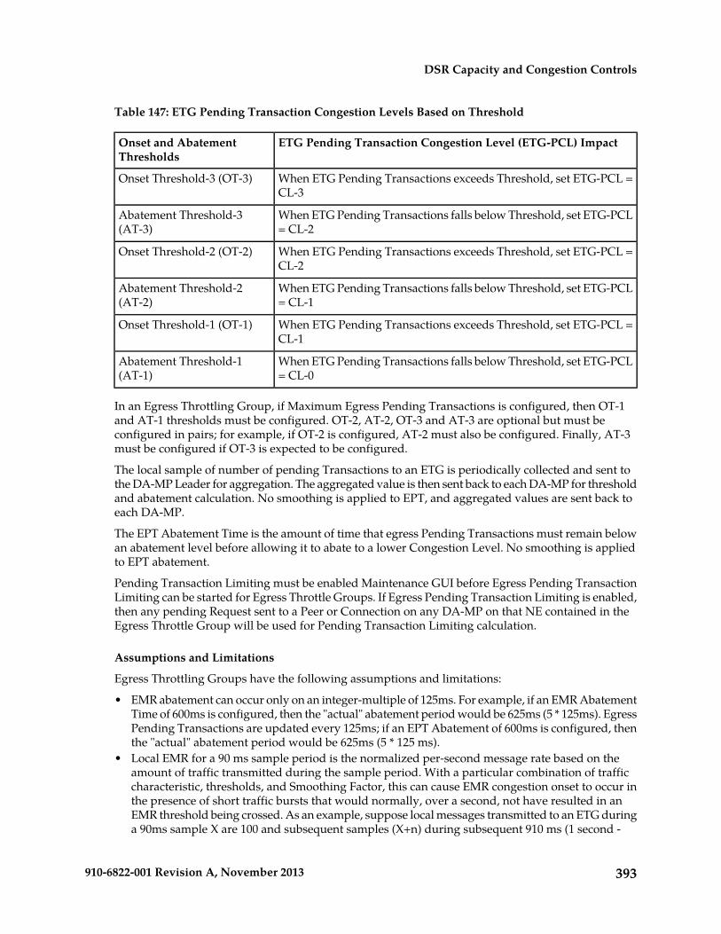
Table 147: ETG Pending Transaction Congestion Levels Based on Threshold
ETG Pending Transaction Congestion Level (ETG-PCL) ImpactOnset and AbatementThresholds
When ETG Pending Transactions exceeds Threshold, set ETG-PCL =CL-3
Onset Threshold-3 (OT-3)
When ETG Pending Transactions falls below Threshold, set ETG-PCL= CL-2
Abatement Threshold-3(AT-3)
When ETG Pending Transactions exceeds Threshold, set ETG-PCL =CL-2
Onset Threshold-2 (OT-2)
When ETG Pending Transactions falls below Threshold, set ETG-PCL= CL-1
Abatement Threshold-2(AT-2)
When ETG Pending Transactions exceeds Threshold, set ETG-PCL =CL-1
Onset Threshold-1 (OT-1)
When ETG Pending Transactions falls below Threshold, set ETG-PCL= CL-0
Abatement Threshold-1(AT-1)
In an Egress Throttling Group, if Maximum Egress Pending Transactions is configured, then OT-1and AT-1 thresholds must be configured. OT-2, AT-2, OT-3 and AT-3 are optional but must beconfigured in pairs; for example, if OT-2 is configured, AT-2 must also be configured. Finally, AT-3must be configured if OT-3 is expected to be configured.
The local sample of number of pending Transactions to an ETG is periodically collected and sent tothe DA-MP Leader for aggregation. The aggregated value is then sent back to each DA-MP for thresholdand abatement calculation. No smoothing is applied to EPT, and aggregated values are sent back toeach DA-MP.
The EPT Abatement Time is the amount of time that egress Pending Transactions must remain belowan abatement level before allowing it to abate to a lower Congestion Level. No smoothing is appliedto EPT abatement.
Pending Transaction Limiting must be enabled Maintenance GUI before Egress Pending TransactionLimiting can be started for Egress Throttle Groups. If Egress Pending Transaction Limiting is enabled,then any pending Request sent to a Peer or Connection on any DA-MP on that NE contained in theEgress Throttle Group will be used for Pending Transaction Limiting calculation.
Assumptions and Limitations
Egress Throttling Groups have the following assumptions and limitations:
• EMR abatement can occur only on an integer-multiple of 125ms. For example, if an EMR AbatementTime of 600ms is configured, then the "actual" abatement period would be 625ms (5 * 125ms). EgressPending Transactions are updated every 125ms; if an EPT Abatement of 600ms is configured, thenthe "actual" abatement period would be 625ms (5 * 125 ms).
• Local EMR for a 90 ms sample period is the normalized per-second message rate based on theamount of traffic transmitted during the sample period. With a particular combination of trafficcharacteristic, thresholds, and Smoothing Factor, this can cause EMR congestion onset to occur inthe presence of short traffic bursts that would normally, over a second, not have resulted in anEMR threshold being crossed. As an example, suppose local messages transmitted to an ETG duringa 90ms sample X are 100 and subsequent samples (X+n) during subsequent 910 ms (1 second -
393910-6822-001 Revision A, November 2013
DSR Capacity and Congestion Controls

90ms) are less than 100 msgs. Local EMR for sample period X will be: 100*(1000ms/90ms) = 1100messages/sec even though in reality the Local Message Rate was lower than 1100 msgs/sec. Witha higher Smoothing Factor, the effect of this limitation can be reduced.
• Because the sampling timer and MP Leader aggregation are asynchronous, the ETG aggregatedrate can lag by up to 250 ms.
Diameter Configuration for Egress Throttle Groups
Egress Throttle Groups are used to perform 2 functions: Rate limiting and Pending Transaction Limiting.Each of the functions are independent of each other and can be optionally configured and controlledseparately.
The Diameter > Configuration > Egress Throttle Groups GUI pages provide fields for configuringeach function. Each function, if configured in the system, must have its Admin State changed to Enabledon the Diameter > Maintenance > Egress Throttle Groups GUI page.
Egress Throttle Groups configuration procedures are provided in Egress Throttle Groups configuration.
Egress Throttle Groups maintenance information and procedures are provided in Egress Throttle Groupsmaintenance.
394910-6822-001 Revision A, November 2013
DSR Capacity and Congestion Controls

Glossary
A
Data AcknowledgementACK
Advanced Encryption StandardAES
A set of conditions that controlmessage routing to a DSR
Application Routing Rule
application based on messagecontent.
American Standard Code forInformation Interchange
ASCII
Application Trouble HandlerATH
Answer Topology Hiding
Answer Topology Restoral (DSR)ATR
Attribute-Value PairAVP
The Diameter protocol consists ofa header followed by one or moreattribute-value pairs (AVPs). AnAVP includes a header and is usedto encapsulate protocol-specificdata (e.g., routing information) aswell as authentication,authorization or accountinginformation.
C
Credit Control AnswerCCA
The Diameter message that isreceived from the prepaid ratingengine to acknowledge a CCRcommand.
395910-6822-001 Revision A, November 2013

C
Capability-Exchange-AnswerCEA
The Diameter response that theprepaid rating engine sends to theMobile Originated applicationduring capability exchanges.
Capabilities-Exchange-RequestCER
A Diameter message that theMobile Originated applicationsends to a prepaid rating engine toperform a capability exchange. TheCER (indicated by theCommand-Code set to 257 and theCommand Flags' 'R' bit set) is sentto exchange local capabilities.Theprepaid rating engine respondswith aCapability-Exchange-Answer(CEA) message.
A mechanism for assigningApplication IDs and supported
CEX Configuration Set
Vendor IDs to a Local Node or toa Connection.
A DSR Application that isresponsible for sending and
Charging Proxy Application
receiving Diameter accountingmessages.
A mechanism for assigning SCTP,Diameter, or TCP options to aconnection.
Connection Configuration Set
Charging Proxy ApplicationCPA
The Charging Proxy Application(CPA) feature defines a DSR-basedCharging Proxy Function (CPF)between the CTFs and the CDFs.The types of CTF include GGSN,PGW, SGW, HSGW, andCSCF/TAS.
396910-6822-001 Revision A, November 2013
Glossary

D
Diameter Agent Message ProcessorDA-MP
A DSR MP (Server Role = MP,Server Group Function = DiameterSignaling Router). A localapplication such as CPA canoptionally be activated on theDA-MP. A computer or blade thatis hosting a Diameter SignalingRouter Application.
Diameter Application ServerDAS
Diameter Edge AgentDEA
Protocol that provides anAuthentication, Authorization, and
Diameter
Accounting (AAA) framework forapplications such as network accessor IP mobility. Diameter works inboth local and roaming AAAsituations.
Diameter can also be used as asignaling protocol for mobilitymanagement which is typicallyassociated with an IMS or wirelesstype of environment. Diameter isthe successor to the RADIUSprotocol. The MPE device supportsa range of Diameter interfaces,including Rx, Gx, Gy, and Ty.
A computer or blade that is hostingthe DSR. Multiple instances of the
Diameter Agent MessageProcessor
DSR each execute on a separatephysical DA-MP. Each instanceshares run-time status informationwith all other instances for theDiameter connections that itcontrols. In inter-MP routing, aninstance can route an ingressAnswer message to anotherinstance that performed routing for
397910-6822-001 Revision A, November 2013
Glossary

D
the corresponding ingress Requestmessage. See DA-MP.
A set of Diameter Nodes identifiedby a Realm name. A Diameter
Diameter Network
Node that initiates a Diametermessage is identified by themandatory Origin-Realm AVP inthe message. A Diameter Node thatis the intended destination of aDiameter message is identified bythe mandatory Destination-RealmAVP in the message.
Domain Name SystemDNS
A system for converting Internethost and domain names into IPaddresses.
Disconnect-Peer-AnswerDPA
A message used by a Diameternode to answer theDisconnect-Peer-Request (DPR).
Disconnect-Peer-RequestDPR
A message used by a Diameternode to inform its peer of its intentto disconnect the transport layer.Upon receipt of a DPR, theDisconnect-Peer-Answer (DPA) isreturned.
Diameter Signaling RouterDSR
A set of co-located MessageProcessors which share commonDiameter routing tables and aresupported by a pair of OAMservers. A DSR Network Elementmay consist of one or moreDiameter nodes.
398910-6822-001 Revision A, November 2013
Glossary

D
Any DSR software feature orfunction that is developed as a userof the Diameter base protocol.
DSR Application
Device-Watchdog-AnswerDWA
A Diameter message used with theDevice-Watchdog-Request (DWR)message to proactively detectconnection failures. If no traffic isdetected on a connection betweenthe Mobile Originated applicationand the prepaid rating enginewithin the configured timeoutperiod, a DWR message is sent tothe prepaid rating engine. If theprepaid rating engine fails torespond with a DWA within therequired time, the connection isclosed with the prepaid ratingengine and initiates failoverprocedures. All new and pendingrequests are then sent to thesecondary server.
Device-Watchdog-RequestDWR
A Diameter message used with theDevice-Watchdog-Answer (DWA)message to proactively detectconnection failures. If no traffic isdetected on a connection betweenthe Mobile Originated applicationand the Diameter server within theconfigured timeout period, a DWRmessage is sent to the DiameterServer. If the Diameter server failsto respond within the requiredtime, the connection is closed withthe Diameter server and initiatesfailover procedures. All new andpending requests are then sent tothe secondary Diameter server.
F
Full Address Based ResolutionFABR
399910-6822-001 Revision A, November 2013
Glossary

F
Provides an enhanced DSR routingcapability to enable networkoperators to resolve the designatedDiameter server addresses basedon individual user identityaddresses in the incomingDiameter request messages.
Federal Information ProcessingStandard
FIPS
Fully qualified domain nameFQDN
The complete domain name for aspecific computer on the Internet(for example, www.tekelec.com).
A domain name that specifies itsexact location in the tree hierarchyof the DNS.
See FABR.Full Address Based Resolution
H
Home Subscriber ServerHSS
A central database for subscriberinformation.
I
International Mobile SubscriberIdentity
IMSI
A unique internal network IDidentifying a mobile subscriber.International Mobile StationIdentity
L
A local Diameter node specifiedwith a fully qualified domain
Local Node
name. It identifies a list of IPaddresses for the Local node, a
400910-6822-001 Revision A, November 2013
Glossary

L
listen port number, supportedtransport types, etc.
M
Mobile Country CodeMCC
A three-digit number that uniquelyidentifies a country served bywireless telephone networks. TheMCC is part of the InternationalMobile Subscriber Identity (IMSI)number, which uniquely identifiesa particular subscriber. See alsoMNC, IMSI.
Message Copy Configuration SetMCCS
Mobility Management EntityMME
Message ProcessorMP
The role of the Message Processoris to provide the applicationmessaging protocol interfaces andprocessing. However, these serversalso have OAM&P components.All Message Processors replicatefrom their Signaling OAM'sdatabase and generate faults to aFault Management System.
N
National Institute of Standards andTechnology
NIST
P
A Diameter node to which a givenDiameter node has a directtransport connection.
Peer
A set of conditions that controlmessage routing to an upstream
Peer Routing Rule
401910-6822-001 Revision A, November 2013
Glossary

P
peer node based on messagecontent.
A timer that limits the maximumtime that Diameter will wait for an
Pending Answer Timer
Answer response from an upstreamPeer Node. This timer is startedwhen a Request message is queuedfor forwarding on a Diameterconnection, and the timer isstopped when an Answer responseto the message is received.
Policy Diameter Relay Agent. Ascalable, geo-diverse DSR
Policy DRA
application that creates a bindingbetween a subscriber and a PCRF,and routes all policy messages fora given subscriber to the PCRF thatcurrently hosts that subscriber’spolicy rules. Policy DRA is capableof performing Topology Hiding tohide the PCRF from the PolicyClient.
A Diameter network whosetopology information is being
Protected Network
hidden by one of the DiameterTopology Hiding features.
Pending Transaction RecordPTR
R
See RBAR.Range Based AddressResolution
Range Based Address ResolutionRBAR
A DSR enhanced routingapplication which allows the userto route Diameter end-to-endtransactions based on ApplicationID, Command Code, “Routing
402910-6822-001 Revision A, November 2013
Glossary

R
Entity” Type, and Routing Entityaddress ranges.
A fundamental element inDiameter is the realm, which is
realm
loosely referred to as domain.Realm IDs are owned by serviceproviders and are used byDiameter nodes for messagerouting.
Request Topology Hiding - ATopology Hiding trigger point that
RTH
identifies a location withinDiameter routing wheretopology-related information in aRequest message is hidden orobscured based upon a set ofTopology Hiding rules.
RouterRTR
Routes all types of SMS traffic.
S
Session Binding Repository - Ahighly available, distributed
SBR
database for storing Diametersession binding data
Stream Control TransmissionProtocol
SCTP
An IETF transport layer protocol,similar to TCP that sends a messagein one operation.
The transport layer for all standardIETF-SIGTRAN protocols.
SCTP is a reliable transportprotocol that operates on top of aconnectionless packet network suchas IP and is functionally equivalent
403910-6822-001 Revision A, November 2013
Glossary

S
to TCP. It establishes a connectionbetween two endpoints (called anassociation; in TCP, these aresockets) for transmission of usermessages.
See SBR.Session Binding Repository
Serving GPRS Support NodeSGSN
T
Transmission Control ProtocolTCP
A connection-oriented protocolused by applications on networkedhosts to connect to one another andto exchange streams of data in areliable and in-order manner.
Topology HidingTH
The CPF will appear as a singlelarge CDF to the CTFs, and
Topology Hiding
vice-versa. CPF topology hidingoccurs for both Request andAnswer messages. When sendinga Request message upstream, itrefers to the hiding of thedownstream (CTF) host ID by theDSR when sending a message tothe upstream (CDF) peer. Topologyhiding involves modifying theOrigin-Host and Origin-RealmAVPs.The removal of Diameter hostnames from messages. This is mostoften required at the boundarybetween two service providers withthe goal of limiting the informationthat another service provider candiscover as a result of Diametertraffic traveling between thecarrier’s networks. For DSR CPA,
404910-6822-001 Revision A, November 2013
Glossary

T
the CPF will appear as a singlelarge CDF to the CTFs, andvice-versa. CPF topology hidingoccurs for both Request andAnswer messages. When sendinga Request message upstream, itrefers to the hiding of thedownstream (CTF) host ID by theDSR when sending a message tothe upstream (CDF) peer. Topologyhiding involves modifying theOrigin-Host and Origin-RealmAVPs.
A Diameter network that does nothave home network topology
Trusted Network
information hidden by theDiameter Topology Hidingfeatures.
U
A Diameter network which hastopology information hidden bythe Topology Hiding features.
Untrusted Network
Uniform Resource IdentifierURI
An internet protocol elementconsisting of a short string ofcharacters that conform to a certainsyntax. The string comprises aname or address that can be usedto refer to a resource.
Coordinated Universal TimeUTC
V
Virtual IP AddressVIP
Virtual IP is a layer-3 conceptemployed to provide HA at a hostlevel. A VIP enables two or moreIP hosts to operate in anactive/standby HA manner. From
405910-6822-001 Revision A, November 2013
Glossary

V
the perspective of the IP network,these IP hosts appear as a singlehost.
Virtual MachineVM
406910-6822-001 Revision A, November 2013
Glossary