eagle gold project
TRANSCRIPT

EAGLE GOLD PROJECT
FROZEN MATERIAL MANAGEMENT PLAN
(INCLUDES ICE-RICH AND NON ICE-RICH PERMAFROST)
Version 2017-01
JULY 2017

THIS PAGE INTENTIONALLY LEFT BLANK

Eagle Gold Project
Frozen Material Management Plan
Document Control
i
DOCUMENT CONTROL
Submission History
Version Number
Version Date
Document Description and Revisions Made
2013-01 Apr 2013 Submission of Ice-Rich Materials Management Plan to support Stage 1 Construction of the Project. Document included a preliminary design for the Ice Rich Overburden Storage Area.
2013-01 Dec 2013
Revisions made to the original submission to encompass all categories of frozen materials. Submission made to the Yukon Water Board in support of the application to amend Type B Water Use License QZ11-013. The amendment application considered the use of water and deposit of waste associated with preliminary construction activities and included the construction and operation of the Dublin Gulch Diversion Channel.
2015-01 Mar 2015
Revisions made to include commitments made during the applications process for the amendment of the Type B WUL QZ11-013 in support of an application to the Yukon Water Board for a Type A Water Use License for the full Construction, Operation and Closure of the Project. Version 2015-01 was also submitted to the Department of Energy, Mines and Resources in support of an application for a Quartz Mining Licence allowing the full Construction, Operation and Closure of the Project.
2017-01 Jul 2017 Revisions made to reflect the current site general arrangement.
Version 2017-01 of the Frozen Materials Management Plan (the Plan) for the Project has been
revised in July 2017 to update Version 2015-01 submitted in March 2015. The table below is
intended to identify modifications to the Plan and provide the rationale for such modifications
Version 2017-01 Revisions
Section Revision/Rationale
3.1
Definitions
Updated definitions to include specific terminology used in the Quartz Mining
License QML-0011 and the Type A Water Use License QZ14-041.
Table 3.2-1
Field Identification and Classification of Frozen
Soils
Updated field classifications to support management and disposal decision
making process.
3.3
Management Strategies Insertion of license conditions from QZ14-041.
3.4
Material Quantities Updates to reflect evolution of frozen material classification and estimates.
Table 3.4-1
Functional Area Ice-Rich Material Volume
Estimates by Classification Type
Updates to reflect the material volume estimates based on the optimized site
layout.
4.4
Specific Considerations Removal of reference to the Dublin Gulch Diversion Channel.
4.4.3 Updated to text to specify that design criteria for cut slopes, for the purpose of
Eagle Gold Project
Frozen Material Management Plan
Table of Contents
ii
Section Revision/Rationale
Cutslope Criteria the Plan, relates to cut slopes into frozen ground.
Removal of reference to the Dublin Gulch Diversion Channel cut slope
geotechnical recommendations.
5.2.3
Design Update Insertion of new section to explain the update to the design of the IROSA.
5.2.4.2
Fill Materials
Insertion of new section to describe the fill materials required for the construction
of the IROSA embankments.
5.2.4.3
Stability Assessment
Insertion of new text to explain stability analyses undertaken as part of the
finalization of the IROSA design.
5.2.4.4
Water Management
General updates to describe components grading practices such that rainfall and
runoff are adequately managed and does not lead to ponding water in the
IROSA.
5.2.5.1
Construction Sequencing
Insertion of new text to provide details on the construction sequencing for the
IROSA containment areas.
5.2.5.3
IROSA Volume Management and
Contingency
Insertion of new text to reflect license conditions regarding monitoring of
remaining volume available in the IROSA.
Appendix A
Geotechnical Design Update and IFC
Drawings
Insertion of the design and stamped issued for construction drawings of the
IROSA.
Eagle Gold Project
Frozen Material Management Plan
Table of Contents
iii
TABLE OF CONTENTS
1 Introduction ............................................................................................................................ 1
1.1 Overview ........................................................................................................................ 1
1.2 Scope ............................................................................................................................. 1
2 Site Description ...................................................................................................................... 4
2.1 Surficial Geology ............................................................................................................ 4
2.2 Permafrost ...................................................................................................................... 4
3 Frozen Material Management Concepts .............................................................................. 6
3.1 Definitions ...................................................................................................................... 6
3.2 Identification and Classification ...................................................................................... 6
3.3 Management Strategies ................................................................................................. 8
3.4 Materials Quantities ..................................................................................................... 10
4 Excavation Management ..................................................................................................... 12
4.1 Field Guidelines for Supervising Excavations .............................................................. 12
4.2 Excavation Methods ..................................................................................................... 15
4.3 Sediment and Erosion Control ..................................................................................... 15
4.4 Specific Considerations................................................................................................ 16
4.4.1 Management Approach ................................................................................. 16
4.4.2 Excavation Procedures ................................................................................. 16
4.4.3 Cutslope Criteria ............................................................................................ 16
5 Storage Management........................................................................................................... 17
5.1 General Frozen Materials............................................................................................. 17
5.1.1 Design Assumptions ...................................................................................... 17
5.1.2 Management Approach ................................................................................. 17
5.1.3 Soil Stockpiles ............................................................................................... 17
5.1.3.1 Soil Stockpile Design .................................................................... 17
5.1.3.2 Foundation Conditions .................................................................. 19
5.1.3.3 Transport and Disposal ................................................................. 19
5.1.3.4 Construction Quality Assurance and Quality Control .................... 19
5.1.4 Monitoring and Surveillance .......................................................................... 19
5.2 Problematic Ice-Rich Materials .................................................................................... 19
5.2.1 Management Approach ................................................................................. 19
5.2.2 Design Concept ............................................................................................. 20
5.2.2.1 Siting and Alignment Selection ..................................................... 20
5.2.2.2 Site Investigation ........................................................................... 20
5.2.2.3 Containment Filter Berm ............................................................... 21

Eagle Gold Project
Frozen Material Management Plan
Table of Contents
iv
5.2.3 Design Update ............................................................................................... 22
5.2.4 Design Criteria ............................................................................................... 23
5.2.4.1 Materials Properties ...................................................................... 23
5.2.4.2 Fill Materials .................................................................................. 23
5.2.4.3 Stability Assessment ..................................................................... 24
5.2.4.4 Water Management ....................................................................... 25
5.2.5 Facility Construction ...................................................................................... 26
5.2.5.1 Construction Sequence ................................................................. 26
5.2.5.2 Transport and Disposal ................................................................. 26
5.2.5.3 IROSA Volume Management and Contingency Storage .............. 27
5.2.5.4 Construction Quality Assurance and Quality Control .................... 27
5.2.6 Monitoring and Surveillance .......................................................................... 28
6 Reporting .............................................................................................................................. 31
7 References ............................................................................................................................ 32
List of Tables
Table 3.2-1: Field Identification and Classification of Frozen Soils ................................................ 7
Table 3.3-1: Management Strategies for Frozen Soils ................................................................... 8
Table 3.4-1: Functional Area Ice-rich Material Volume Estimates by Classification Type............ 11
Table 5.2-1: Estimated Storage Capacity and Volume of Berm Material ...................................... 22
Table 5.2-2: Material Properties .................................................................................................... 23
List of Figures
Figure 1.1-1: Project Location Map .................................................................................................. 3
Figure 4.1-1: Classification for Description of Frozen Ground ....................................................... 13
Figure 5.2-1: Haggart Creek Ice-Rich Overburden Storage Area .................................................. 29
Figure 5.2-2: Suttles Gulch Ice-Rich Overburden Storage Area .................................................... 30
List of Appendices
Appendix A Geotechnical Design Update and IFC Drawings

Eagle Gold Project
Frozen Material Management Plan
Section 1 Introduction
1
1 INTRODUCTION
1.1 OVERVIEW
StrataGold Corporation (SGC), a directly held, wholly owned subsidiary of Victoria Gold Corp., has proposed to
construct, operate, close, and reclaim a gold mine in central Yukon. The Eagle Gold Project (“the Project”) is
located 85 km from Mayo, Yukon on existing highway and access roads (Figure 1.1-1). The Project will involve
open pit mining at a production rate of approximately 10 million tonnes per year (Mt/y) ore and an average strip
ratio (amount of waste: amount of ore) of 1.45:1.0 over approximately 10 years.
Earthworks construction and some operational activities of the Project will result in the excavation and exposure
of frozen overburden soils, identified as either permafrost or from within the active zone that freezes seasonally.
Frozen soils at the project site consist of:
fine and/or coarse-grained colluvial/alluvial soils or weathered bedrock with little or no ice content,
coarse-grained sands and gravels with zones of variable ice content,
fine-grained soils with relatively thin zones (lenses) and low proportions of “excess ice”, and
fine-grained silty and clayey soils with relatively thick lenses of highly visible “excess ice”.
The term “excess ice” is used to describe ice that occupies a larger pore space in the soil than water in an
unfrozen state. When this ice thaws, the resulting water exceeds the water holding capacity of the soil and
excess water will be present. Some of the frozen soil with excess ice, hereafter called “ice rich”, may become
unstable upon thawing, particularly if it is fine-grained and excess pore water pressure cannot drain readily.
Some of these materials, which could potentially be useful in closure activities (e.g. as cover for reclamation)
while thawing and draining, may require temporary containment during construction and operation of the mine.
This plan describes the management of frozen materials, and how some of the ice-rich materials will be
managed separately from other frozen overburden soils.
1.2 SCOPE
This frozen materials management plan includes:
descriptions of existing site conditions pertinent to materials management;
protocols for characterizing the nature and extent (lateral and vertical) of frozen materials encountered
during construction activities including characterizing the presence and extent of excess ice;
protocols for determining whether encountered frozen material is thaw stable or thaw unstable;
estimated quantities of frozen materials to be handled during construction distinguishing between
material types and different approaches for their management;
descriptions of appropriate handling requirements for each frozen material type, including protocols for
excavation and removal of thaw unstable material from drainage channels, valley walls, etc…

Eagle Gold Project
Frozen Material Management Plan
Section 1 Introduction
2
design criteria and preliminary engineering for an ice rich overburden storage area;
construction quality assurance and quality control planning for the ice rich overburden storage area;
protocols for recording and reporting on the characterization and management of frozen soils (including
thaw stable and unstable materials), and
monitoring plans for stability and associated water management.
This plan addresses the identification, field practices and overall management of all frozen materials, including
permafrost and ice-rich soils as defined herein.

_̂
!
! !
_̂
Elsa
Mayo
Keno Hill
400000
400000
450000
450000
500000
500000
7050
000
7100
000
7100
000
EAGLE GOLD PROJECTYUKON TERRITORY
Projection: Drawn By:
Date: Figure:
Legend:
³!
!
!
!
!
!
! !
!
!
!
!
!
!
!
!
!
!
!
! !
!!
!
!
!
!
!
!
!
"
!
!
!
!
_̂
NORTHWESTTERRITORIES
YUKONTERRITORY
ALASKA
Beaufort Bay
Great BearLake
Faro
ElsaMayo
Atlin
Deline
Wha TiTulita
Inuvik
Holman
Teslin
Dawson
Aklavik
Wrigley
Old Crow
Paulatuk
Carcross
Carmacks
Kugluktuk
Fort Liard
Ross River
Fort Nelson
Tuktoyaktuk
Watson Lake
Tsiigehtchic
Norman Wells
Fort St. John
Sachs Harbour
Fort McPhersonFort Good Hope
Pelly Crossing
HainesJunction
Whitehorse
Eagle Gold Project
0 6 123Kilometres
_̂ Eagle Gold ProjectStrataGold ClaimsOther Claims
! Town / VillageRoadWatercourse
Category A Settlement LandCategory B Settlement Land
#
Haggart Creek Road #
South McQuestenRoad
#
Silver Trail
NAD 83 Zone 8N HC
2017/03/15 1.1-1Project Location

Eagle Gold Project
Frozen Material Management Plan
Section 2 Site Description
4
2 SITE DESCRIPTION
The Dublin Gulch site has been described and characterized extensively in other reports. Surficial geological
and permafrost conditions are relevant to this plan and so are summarised herein, for ease of reference.
2.1 SURFICIAL GEOLOGY
The surficial geology of the Dublin Gulch area has been mapped by Bond (1998). Pleistocene and Holocene
colluvial deposits are abundant in the Project area and generally consist of diamicton, gravel, shattered bedrock,
lenses of sand and silt derived from bedrock, and surficial materials derived by a variety of chemical and
physical weathering processes. These deposits overlie weathered to fresh bedrock. Transport of surface
material occurs as creep and sheetwash; local shallow mass wasting processes occur on certain slopes in the
area.
A till blanket was mapped along the east side of Haggart Creek south of its confluence with Dublin Gulch and
into the lower Dublin Gulch valley. Glacial till occurred in patches in specific zones within the Dublin Gulch and
Haggart Creek valleys due to the main flow directions of regional Cordilleran ice and the area physiography, and
in most cases where present, was disturbed by historical placer mining. Remnants of the till deposits occur
along the east Haggart Creek valley wall and south Dublin Gulch valley wall. In these locations the till is
generally either a clayey or silty sand matrix with some proportion of larger clasts up to cobble size. Although
their distribution has not been mapped, large-boulder (> 1 m) sized erratics have been observed in the Dublin
Gulch valley including within some of the placer tailings (i.e., alluvial materials reworked by placer mining)
upstream of the confluence with Ann Gulch, but not in the Haggart Creek valley.
The Haggart Creek valley in the area of the Project site is filled with a mix of alluvial deposits and placer tailings.
At the valley walls, alluvium, where present, grades imperceptibly into colluvium. Bedrock is exposed along the
creek bottom or banks in several locations along the length of the placer disturbed area.
2.2 PERMAFROST
The Project is located in a region of widespread discontinuous permafrost (Brown, 1979). On the regional scale,
permafrost distribution is typically controlled by mean annual temperature and precipitation, whereas on a local
scale it is controlled by vegetation, surface sediments, soil moisture, slope aspect, and snow depth. Within the
Project area, frozen ground occurs typically on north- and east-facing slopes at higher elevations, and within
poorly drained areas lower in the valleys. Based on site characterization work completed during 2009 to 2012
(BGC 2010, 2011 and 2012a), the distribution and thickness of permafrost is highly variable across the site,
sporadic or non-existent in some areas (south-facing slopes) to more prevalent in other areas (north-facing
slopes at lower elevations). Within the permafrosted areas, the distribution of excess ice and its lateral and
vertical extent is also highly variable. In general, permafrost with zones of excess ice exceeding 1 m in
thickness and laterally continuous over 25 m is limited to the lower north-facing slopes within the lower regions
of the Eagle Pup and Suttles Gulch valleys, including the interfluvial areas between these valleys.
Frozen ground, when observed, is generally encountered immediately below the organic cover. Ground
temperatures have been measured with thermistors installed on site in 1995-1996, and 2009-2012. The

Eagle Gold Project
Frozen Material Management Plan
Section 2 Site Description
5
measured ground temperatures showed the frozen ground to be relatively warm when observed, typically
between 0C and -1C.
Eagle Gold Project
Frozen Material Management Plan
Section 3 Frozen Material Management Concepts
6
3 FROZEN MATERIAL MANAGEMENT CONCEPTS
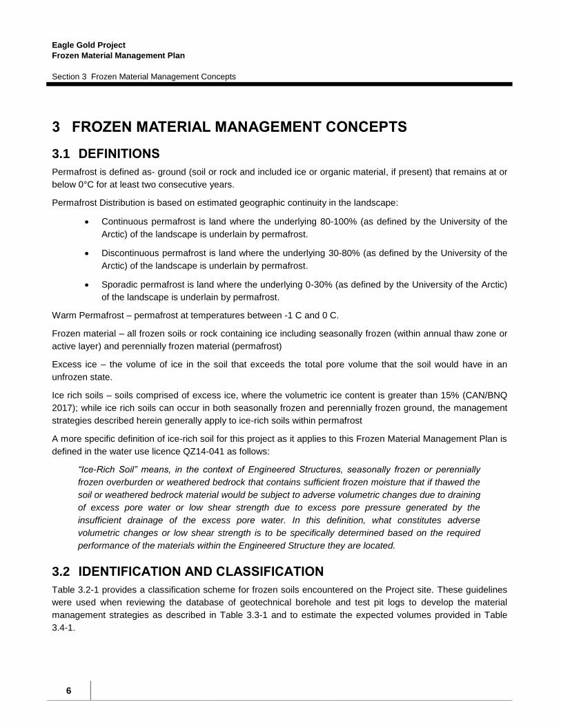
3.1 DEFINITIONS
Permafrost is defined as- ground (soil or rock and included ice or organic material, if present) that remains at or
below 0°C for at least two consecutive years.
Permafrost Distribution is based on estimated geographic continuity in the landscape:
Continuous permafrost is land where the underlying 80-100% (as defined by the University of the
Arctic) of the landscape is underlain by permafrost.
Discontinuous permafrost is land where the underlying 30-80% (as defined by the University of the
Arctic) of the landscape is underlain by permafrost.
Sporadic permafrost is land where the underlying 0-30% (as defined by the University of the Arctic)
of the landscape is underlain by permafrost.
Warm Permafrost – permafrost at temperatures between -1 C and 0 C.
Frozen material – all frozen soils or rock containing ice including seasonally frozen (within annual thaw zone or
active layer) and perennially frozen material (permafrost)
Excess ice – the volume of ice in the soil that exceeds the total pore volume that the soil would have in an
unfrozen state.
Ice rich soils – soils comprised of excess ice, where the volumetric ice content is greater than 15% (CAN/BNQ
2017); while ice rich soils can occur in both seasonally frozen and perennially frozen ground, the management
strategies described herein generally apply to ice-rich soils within permafrost
A more specific definition of ice-rich soil for this project as it applies to this Frozen Material Management Plan is
defined in the water use licence QZ14-041 as follows:
“Ice-Rich Soil” means, in the context of Engineered Structures, seasonally frozen or perennially
frozen overburden or weathered bedrock that contains sufficient frozen moisture that if thawed the
soil or weathered bedrock material would be subject to adverse volumetric changes due to draining
of excess pore water or low shear strength due to excess pore pressure generated by the
insufficient drainage of the excess pore water. In this definition, what constitutes adverse
volumetric changes or low shear strength is to be specifically determined based on the required
performance of the materials within the Engineered Structure they are located.
3.2 IDENTIFICATION AND CLASSIFICATION
Table 3.2-1 provides a classification scheme for frozen soils encountered on the Project site. These guidelines
were used when reviewing the database of geotechnical borehole and test pit logs to develop the material
management strategies as described in Table 3.3-1 and to estimate the expected volumes provided in Table
3.4-1.

Eagle Gold Project
Frozen Material Management Plan
Section 3 Frozen Material Management Concepts
7
These field identification and classification guidelines will be primarily used in the field when preparing for and
during excavation activities to classify frozen materials into the five management types. The classifications will
be used to guide the field geologist, engineer or technician responsible for monitoring construction activities. It is
expected that the specific criteria in Table 3.2-1 and management strategies provided in Table 3.3-1 will be
refined in the field during clearing, grubbing and material segregation activities, as needed, based on the visual
inspections of cleared and grubbed areas (including the cut banks and upslope areas), with consideration of the
duration of exposure, and based on observations of surface water quality monitoring of meltwater ditches and
sediment basins, and the results of excavating, transporting and storing materials selected for disposal in the ice
rich overburden storage area (IROSA). More detailed description of field activities and responsibilities are
outlined in Section 4 (Excavation Management).
Table 3.2-1: Field Identification and Classification of Frozen Soils
Material
Classification
Type
Frozen Material Type Guidelines for Field Classification
Soil Properties USCS Soil
Types
Lateral Extent of
Ice-bearing soils
% of Ice Ice-Bearing Soil Layer
Thickness
I
Fine and/or coarse-
grained colluvial or
alluvial soils, or
weathered bedrock
GW, GP, GM,
GC, SW, SP,
SM, SC, ML, CL,
MH and CH
Limited to isolated
zones (<5-10% of
exposure), not
laterally
continuous
Little (< 5%) or
no ice content
Soil layers less than 0.5 m
thick and separated by >
1.0 m of non-ice-bearing
material
II
Coarse-grained sands
and gravels (> 50%
retained on No. 200
(0.075 mm) sieve)
GW, GP, GM,
GC, SW, SP, SM
and SC
Limited to isolated
zones (< 20% of
exposure), not
laterally
continuous
Zones of
variable ice
content - up to
10% excess ice
Relatively thin soil layers <
0.5 m thick
III Fine-grained soils (>
50% silts and clays)
ML, CL, MH and
CH
Limited to isolated
zones (<5-10% of
exposure), not
laterally
continuous
Low proportions
(<5-10%) of
“excess ice”
relatively thin (< 0.5 to 1.0
m thick) soil layers
IV Fine-grained soils (>
50% fines)
ML, CL, MH and
CH
Laterally
continuous
throughout
exposure; multiple
lenses
Readily visible
(>10%) “excess
ice”
with relatively thick (> 1 m)
soil layers
V
Small quantities of
ice-rich soils (fine or
coarse)
GW, GP, GM,
GC, SW, SP,
SM, SC, ML, CL,
MH and CH
Overall volume is
less than 10% of
potential fill area
Variable ice
content - up to
20% excess ice
Relatively thin soil layers <
1.0 m thick

Eagle Gold Project
Frozen Material Management Plan
Section 3 Frozen Material Management Concepts
8
Note – organic soils (OH, OL and Pt with or without ice) will be excavated and stockpiled for reclamation purposes; reclamation stockpile
will be designed to contain some ice-rich material, which will be allowed to thaw and drain (to sediment basins as per the construction
water management plan), and then re-graded.
3.3 MANAGEMENT STRATEGIES
Frozen ground, where encountered, contains varying amounts of ice, and in some cases can be considered as
“excess ice” (as defined above), as described in the detailed records of test pits and cored geotechnical
drillholes used to characterize the site by Knight Piésold (1996a and 1996b), Sitka Corp. (1996) and BGC
(2010, 2011, 2012a, 2012b and 2016). Based on this previous work, it is apparent that frozen ground will be
encountered during construction of a number of proposed project facilities, primarily on north-facing slopes.
Frozen soils will be identified as one of five material management types using initially previous data, confirmed
in the field during clearing, grubbing and general earthworks activities, and then managed as described in Table
3.3-1.
Table 3.3-1: Management Strategies for Frozen Soils
Material
Classification
Type
Frozen Material Type Strategy Management Description
I Fine and/or coarse-grained
colluvial/alluvial soils or
weathered bedrock with little
or no ice content
Used as Fill or
Stockpiled for
Closure
Used as general fill or if excess to a local
fill requirement stored for reclamation.
II Coarse-grained sands and
gravels with zones of variable
ice content
Used as Fill Exposed and readily thawed and drained,
and then used as general fill within
embankments and platforms.
III Fine-grained soils with
relatively thin zones (lenses)
of low proportions of “excess
ice”
Stockpiled for
closure
Separated and co-disposed with other non-
frozen soils within stockpiles to be used for
reclamation.
IV Fine-grained silty and clayey
soils with relatively thick
lenses of highly visible
“excess ice”
To IROSA Segregated at excavation site based on
prior field data/information, and additional
observations during excavations.
Excavated and hauled to the ice-rich
overburden storage area located in the
Haggart Creek valley.
V Small quantities of ice-rich
soils (fine or coarse)
Locally stored Disposed of adjacent to excavation sites
where thawing and drainage can be
managed locally rather than hauled to the
Eagle Gold Project
Frozen Material Management Plan
Section 3 Frozen Material Management Concepts
9
IROSA.
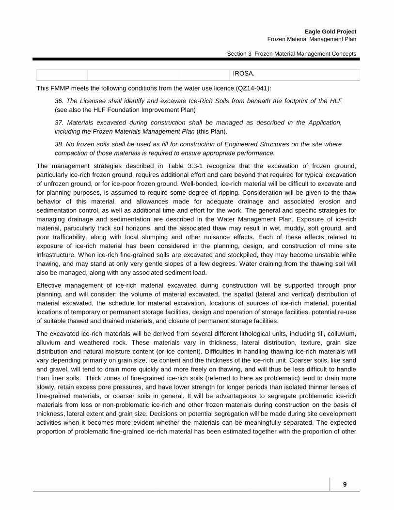
This FMMP meets the following conditions from the water use licence (QZ14-041):
36. The Licensee shall identify and excavate Ice-Rich Soils from beneath the footprint of the HLF
(see also the HLF Foundation Improvement Plan)
37. Materials excavated during construction shall be managed as described in the Application,
including the Frozen Materials Management Plan (this Plan).
38. No frozen soils shall be used as fill for construction of Engineered Structures on the site where
compaction of those materials is required to ensure appropriate performance.
The management strategies described in Table 3.3-1 recognize that the excavation of frozen ground,
particularly ice-rich frozen ground, requires additional effort and care beyond that required for typical excavation
of unfrozen ground, or for ice-poor frozen ground. Well-bonded, ice-rich material will be difficult to excavate and
for planning purposes, is assumed to require some degree of ripping. Consideration will be given to the thaw
behavior of this material, and allowances made for adequate drainage and associated erosion and
sedimentation control, as well as additional time and effort for the work. The general and specific strategies for
managing drainage and sedimentation are described in the Water Management Plan. Exposure of ice-rich
material, particularly thick soil horizons, and the associated thaw may result in wet, muddy, soft ground, and
poor trafficability, along with local slumping and other nuisance effects. Each of these effects related to
exposure of ice-rich material has been considered in the planning, design, and construction of mine site
infrastructure. When ice-rich fine-grained soils are excavated and stockpiled, they may become unstable while
thawing, and may stand at only very gentle slopes of a few degrees. Water draining from the thawing soil will
also be managed, along with any associated sediment load.
Effective management of ice-rich material excavated during construction will be supported through prior
planning, and will consider: the volume of material excavated, the spatial (lateral and vertical) distribution of
material excavated, the schedule for material excavation, locations of sources of ice-rich material, potential
locations of temporary or permanent storage facilities, design and operation of storage facilities, potential re-use
of suitable thawed and drained materials, and closure of permanent storage facilities.
The excavated ice-rich materials will be derived from several different lithological units, including till, colluvium,
alluvium and weathered rock. These materials vary in thickness, lateral distribution, texture, grain size
distribution and natural moisture content (or ice content). Difficulties in handling thawing ice-rich materials will
vary depending primarily on grain size, ice content and the thickness of the ice-rich unit. Coarser soils, like sand
and gravel, will tend to drain more quickly and more freely on thawing, and will thus be less difficult to handle
than finer soils. Thick zones of fine-grained ice-rich soils (referred to here as problematic) tend to drain more
slowly, retain excess pore pressures, and have lower strength for longer periods than isolated thinner lenses of
fine-grained materials, or coarser soils in general. It will be advantageous to segregate problematic ice-rich
materials from less or non-problematic ice-rich and other frozen materials during construction on the basis of
thickness, lateral extent and grain size. Decisions on potential segregation will be made during site development
activities when it becomes more evident whether the materials can be meaningfully separated. The expected
proportion of problematic fine-grained ice-rich material has been estimated together with the proportion of other

Eagle Gold Project
Frozen Material Management Plan
Section 3 Frozen Material Management Concepts
10
frozen/non-frozen material where other material management practices can be used (i.e., identifying soils that
can be readily stockpiled with other closure soils).
3.4 MATERIALS QUANTITIES
BGC (2012c) provided a preliminary estimate of the volume of ice-rich soils that may be encountered during the
construction of Project facilities. This preliminary estimate did not qualify whether the frozen ground met the
criteria for ice-rich soils (i.e., all frozen ground was lumped together independent of volumetric ice content) and
the estimate did not segregate the ice-rich soils for management strategy. Further, the estimate was derived
using an earlier General Arrangement (GA) (i.e., assumed for the 2012 Feasibility Study). Based on additional
field work and reconnaissance, the current GA, and a detailed assessment of test pit logs, photos and borehole
records the estimate was further refined and segregated based on ice content, and the thickness, lateral extent
and grain size of the ice-rich soil horizon/layer into material management strategy types described in Table 3.3-
1. This strategy distinguishes between potentially ice-rich fine grained soils which must be fully contained
(referred to here as problematic or Type IV soils in Table 3.3-1), other frozen materials that may either be
directly utilized for engineered fill (Type II) or which may be directly co-disposed with soils designated for
closure stockpiling (Type III). The estimated quantity of problematic ice-rich soils expected to be hauled and
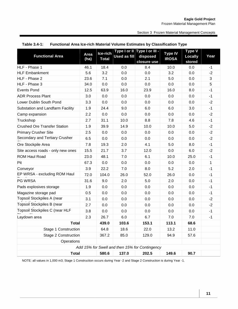
stored within the IROSA is approximately 113,100 m3 (plus 15% for swell and 15% for contingency).
Approximately 12% of this material is expected to be generated in the first year of construction.
Eagle Gold Project
Frozen Material Management Plan
Section 3 Frozen Material Management Concepts
11
Table 3.4-1: Functional Area Ice-rich Material Volume Estimates by Classification Type
Functional Area Area (ha)
Ice-rich
Total
Type I or II
Used as fill
Type I or III -
disposed
closure use
Type IV
IROSA
Type V
Locally
stored
Year
HLF - Phase 1 46.1 18.4 0.0 8.4 10.0 0.0 -1
HLF Embankment 5.6 3.2 0.0 0.0 3.2 0.0 -2
HLF - Phase 2 23.6 7.1 0.0 2.1 5.0 0.0 3
HLF - Phase 3 34.0 0.0 0.0 0.0 0.0 0.0 5
Events Pond 12.5 63.9 16.0 23.9 16.0 8.0 -1
ADR Process Plant 3.0 0.0 0.0 0.0 0.0 0.0 -1
Lower Dublin South Pond 3.3 0.0 0.0 0.0 0.0 0.0 -2
Substation and Landfarm Facility 1.9 24.4 9.0 6.0 6.0 3.0 -1
Camp expansion 2.2 0.0 0.0 0.0 0.0 0.0 -2
Truckshop 2.7 31.1 10.0 8.8 7.8 4.6 -1
Crushed Ore Transfer Station 1.9 39.9 14.9 10.0 10.0 5.0 -2
Primary Crusher Site 2.5 0.0 0.0 0.0 0.0 0.0 -2
Secondary and Tertiary Crusher Sites
6.5 0.0 0.0 0.0 0.0 0.0 -2
Ore Stockpile Area 7.8 19.3 2.0 4.1 5.0 8.0 -1
Site access roads - only new ones 15.5 21.7 3.7 12.0 0.0 6.0 -2
ROM Haul Road 23.0 48.1 7.0 6.1 10.0 25.0 -1
Pit 67.3 0.0 0.0 0.0 0.0 0.0 1
Conveyor 3.9 22.2 7.0 8.0 5.2 2.0 -1
EP WRSA - excluding ROM Haul Road
72.0 104.0 26.0 52.0 26.0 0.0 -1
PG WRSA 31.6 9.0 2.0 5.0 2.0 0.0 -1
Pads explosives storage 1.9 0.0 0.0 0.0 0.0 0.0 -1
Magazine storage pad 0.5 0.0 0.0 0.0 0.0 0.0 -1
Topsoil Stockpiles A (near substation)
3.1 0.0 0.0 0.0 0.0 0.0 -2
Topsoil Stockpiles B (near conveyor)
2.7 0.0 0.0 0.0 0.0 0.0 -2
Topsoil Stockpiles C (near HLF Phase 1)
3.8 0.0 0.0 0.0 0.0 0.0 -1
Laydown area 2.3 26.7 6.0 6.7 7.0 7.0 -1
Total 439.0 103.6 153.1 113.1 68.6
Stage 1 Construction 64.8 18.6 22.0 13.2 11.0
Stage 2 Construction 367.2 85.0 129.0 94.9 57.6
Operations
Add 15% for Swell and then 15% for Contingency
Total 580.6 137.0 202.5 149.6 90.7
NOTE: all values in 1,000 m3; Stage 1 Construction occurs during Year -2 and Stage 2 Construction is during Year -1.

Eagle Gold Project
Frozen Material Management Plan
Section 4 Excavation Management
12
4 EXCAVATION MANAGEMENT
4.1 FIELD GUIDELINES FOR SUPERVISING EXCAVATIONS
There is an extensive set of background subsurface geotechnical data for the Dublin Gulch area collected over
the past several years, which is in addition to that collected by prior operators during the 1990’s. This data was
collected and logged by engineering professionals using professional judgment and standard engineering field
classification practices. The subsurface data sets were collected for site-specific areas identified for excavation
and construction activities.
Following best management practices (BMPs) for construction activities (i.e., using professional geotechnical
field staff experienced in identifying soils and rocks in permafrost terrain and construction operators and
managers experienced in permafrost field conditions), and adaptive management practices for incorporating
site-specific field information collected during the construction process are key factors for the successful
execution of this Plan. One of the primary objectives for those supervising excavation will be to segregate frozen
materials into the five types as described in the Table 3.2-1.
The purpose of the classification structure presented in Table 3.2-1 is to provide a set of field guidelines to
support standard best practices for supervising excavation activities where materials will be classified and
sorted for particular uses (e.g., structural fill, road base, top soil, potential reclamation cover material, etc.). A
typical sequence for a particular construction area will include:
1) detailed review of construction plans for cutting/filling in a specific area,
2) detailed review of the existing data from air photos, test pits and borings,
3) field assessment of the site-specific terrain to undergo construction including reconnaissance across the
terrain to be excavated, along existing road cuts, and to the locations of previous test pits,
4) conducting additional site investigations, if needed, in specific areas,
5) implementing erosion and sediment control measures as stipulated in the Water Management Plan,
6) initiating excavation and material haulage as dictated by cut and fill balances specified in facility
designs, while classifying and segregating materials for specific uses or storage,
7) implementing adaptive management practices based on the observed feasibility and/or continuing need
of executing the classification guidelines, and
8) modifying the classification system, as needed, to achieve the most efficient, cost effective way and
environmentally sound method to manage the excavations and material management at the site; this
would include achieving lower environmental impact due to minimizing construction vehicle usage,
requiring minimal material movement, and maintaining more local material sources that would be
available for future reclamation purposes.
In general, the field supervisor (a geologist, engineer or technician) will record and document their observations
prior to and during all excavation activities using standard practices. These would include general descriptions
Eagle Gold Project
Frozen Material Management Plan
Section 4 Excavation Management
13
of soil and bedrock type, stratigraphy (lateral and vertical extent) of units exposed or as determined by
interpolating between boreholes and test pits, soil properties (USCS Soil Type), lateral and vertical extents of
ice-bearing soils, including the percentage of ice of each unit or sub-unit as necessary. Representative samples
will be collected from borehole cores, test pits or excavation faces for grain size analyses conducted in the field.
In addition, approximate ice volumes or percentages, using a 5 cm diameter core or bulk sample of an
approximate volume, will be estimated (following the classification system shown in Figure 4.1-1).
Figure 4.1-1: Classification for Description of Frozen Ground

Eagle Gold Project
Frozen Material Management Plan
Section 4 Excavation Management
14
The objective will be to provide estimates of the bulk ice content across an area, including volumetric estimates
for the stable and thaw unstable zones (i.e., as classified into the types identified in Table 3.2-1).
The responsibility of the field supervisor also includes monitoring the following areas: any headwall retreat of the
cutslope, re-vegetation, channeling and rilling of slope face, type/nature of any failures (slump, drip, crumble or
block fail), and rates of sediment accumulation in ditches and sediment basins. The field supervisor, in

Eagle Gold Project
Frozen Material Management Plan
Section 4 Excavation Management
15
conjunction with the construction foreman, will attempt to minimize the duration of the disturbance and confirm
that slope stabilization and re-vegetation measures based on observed field conditions are implemented as
soon as practicable or institute adaptive management measures (e.g., change cutslope angles, add sediment
basins, etc.).
4.2 EXCAVATION METHODS
Generally, drilling and blasting of frozen materials will not be required. Where site-specific conditions indicate
that the BMP for ice-rich material will be excavation and removal to the IROSA a shovel, equipped with a ripper
tooth, as necessary, will be employed with transport of any excavated material to the IROSA via a haul truck.
Based on-site experience in building exploration roads and excavating trenches and test pits, thinner pocket
layers of poorly to moderately bonded coarse-grained ice-rich material can be excavated with a shovel; thicker
layers of well-bonded fine-grained ice-rich material will require ripping with a shovel tooth.
4.3 SEDIMENT AND EROSION CONTROL
Sediment and erosion control measures will be implemented and maintained to ensure that excavations do not
results in discharge of sediment-laden water to the receiving environment without adequate controls. Sediment
mobilizations and erosion will be minimized by using the following measures.
Limiting the extent of land disturbances to the practical minimum.
Reducing water velocities across the ground using soil bioengineering, surface roughening, sediment
logs, and recontouring.
Reseeding disturbed land and constructing drainage controls to improve stability.
Constructing sediment control devices, such as collection and diversion ditches, sediment traps, in-
channel energy dissipaters, and sediment basins.
Installing rock riprap, channel lining, sediment filters, or other suitable measures in ditches on steep
gradients as required.
Restricting access to re-vegetated and stabilized areas.
Directing all sediment-laden runoff to the appropriate sediment control measure.
Constructing appropriate temporary BMPs (e.g., silt fences, hay bales) downslope of disturbed sites
where more permanent sediment control measures are not appropriate or in combination with
permanent measures.
A description of these measures, their construction considerations, and follow up monitoring are provided in the
Water Management Plan (WMP) and must be followed for all excavations.

Eagle Gold Project
Frozen Material Management Plan
Section 4 Excavation Management
16
4.4 SPECIFIC CONSIDERATIONS
4.4.1 Management Approach
The management of frozen ground during construction and the effects of that construction are approached on a
site-wide basis, as described herein, and by related plans (for example, the Water Management Plan and the
Environmental Monitoring, Surveillance and Adaptive Management Plan). The management of ice-rich soils
during preparation of the HLF is dealt with in more detail in the HLF Foundation Improvement Plan due to
specific conditions in both the water use and quartz mine licences.
4.4.2 Excavation Procedures
With respect to excavations in permafrost, and while keeping in mind criteria for cut slope gradients, the vertical
face of the top of the cutslope, could be steepened so that natural stabilization using in-situ vegetation can take
place. In this case, it is preferable to allow the vegetative mat to drape over the top edge to shade the interface
between the slope and the original ground, so this part of the area should not be stripped. Also, in many cases,
larger trees on the edge should be hand cut, to minimize the collapse of the tree onto the exposed slope face so
that the organic mat is not torn and more permafrost is exposed. On flatter cut slopes, a windrow of vegetative
mat could be stripped and conserved for later machine spreading onto the stripped area. If frozen gravels
(coarser materials in general) are exposed in the cutslope, the slope can be re-graded and stabilized to allow
natural re-vegetation processes to reclaim the cut.
In a few locations, an excavation may also expose permafrost with excess ice. In these cases, the zone will be
over-excavated, as needed, to a depth where the thickness of backfill (coarse sand and gravels) will provide
sufficient insulation to minimize any effect from the potential thawing of permafrost.
4.4.3 Cutslope Criteria
Field investigations in support of geotechnical recommendations for design of Project infrastructure were
undertaken in 2009, 2010, 2011 and 2012. Based on the observed subsurface conditions for the Project site
and generally accepted engineering practices, recommended slope geometry was developed for permanent cut
slopes and engineered fill slopes for various Project components.
The recommended slope geometry developed for certain permanent cut slopes into frozen ground indicated that
a steepest cut slope angle of 2.5H:1V in overburden and 2H:1V in till should be used . The geotechnical
recommendations also suggested that engineered fill slopes constructed of structural fill or rock fill should be at
angles of 2H:1V or flatter.

Eagle Gold Project
Frozen Material Management Plan
Section 5 Storage Management
17
5 STORAGE MANAGEMENT
5.1 GENERAL FROZEN MATERIALS
5.1.1 Design Assumptions
This section describes the management strategies for material types I, II, III and V. Management strategy for
Type IV (problematic) soils is described in Section 5.2.
The reclamation stockpile areas will be managed in the same manner as all other construction areas by means
of interception and diversion of runoff around and away from the disturbance areas. Stockpile areas will be set
out so that sediment from erosion is trapped and contained locally in swales and depressions, making use of
more competent soils to form containment berms. The drainage management of the stockpile areas will be
integral with general construction water management measures across the site and is described in more detail
in the Water Management Plan.
5.1.2 Management Approach
The Mined Rock and Overburden Piles Investigation and Design Manual Interim Guidelines (Design Manual)
(Piteau 1991). provides the general criteria that will be used for each soils stockpile constructed on site.
Relatively small quantities of ice rich fine-grained soils can be feasibly and practicably co-disposed with larger
quantities of overburden soils in gently sloping areas. If required, toe berms will be constructed to provide
containment against flowsliding in an uncontrolled manner.
Frozen soils that do not exhibit flow sliding potential (Types I or III) will be co-disposed with overburden soils set
aside for closure. The stability of closure soil stockpiles is addressed separately, but it is assumed that the
geotechnical properties of any frozen co-disposed soils will exhibit similar stability to the closure materials
sourced from other non-frozen areas. Alternatively, closure materials could be placed in zones that ensure the
stability and containment of the frozen soils (upon thawing).
Frozen soils found to be suitable for use as general fill (Type II), that meet criteria for engineered compacted
fills, when thawed and drained, will be used accordingly. Their properties will be similar to other cut materials
judged suitable for fill or storage in stockpiles where there is an excess above the required fill volume. This
material could also ultimately be used for closure.
5.1.3 Soil Stockpiles
5.1.3.1 Soil Stockpile Design
Soil salvage is the removal of soil after vegetation has been cleared and transport of soil by haul trucks to
designated long-term storage sites. This includes selected frozen soils (Types I and III) that are not judged to
be so wet, ice-rich or fine grained that their presence will cause instability in the stockpiles. Selection of the
stockpile locations has taken into account:
Volume of soil that must be stored,

Eagle Gold Project
Frozen Material Management Plan
Section 5 Storage Management
18
Topography (in some instances site preparation to level the area, or to stabilize it in areas of permafrost
will need to be completed),
Avoidance of natural drainages, and
Travel distances.
Soil stockpiles will be created at several locations at the site. Advantage can be taken of access and haul road
embankments to contain weaker materials, and to provide localized sedimentation ponds.
Careful zoning of the stockpiles will facilitate retrieval of selected materials required for closure, and also can
result in improved stability by utilizing better drained stronger materials to contain weaker ones.
Also, stripped soils ultimately needed for closure will be stored as close as practical to sites where they will be
required, taking advantage of local swales and depressions. All stripped soils, whether frozen or not, and
whether ice rich or not, are regarded as very valuable for closure, and will be carefully placed for ease of
retrieval.
Soil stockpile storage volumes are based on stockpile heights between 8 to 10 m and slopes of about 2H:1V.
The precise slope angle will be determined on the basis of geotechnical evaluation of both specific foundation
conditions as encountered, and the actual materials requiring storage.
BMPs and mitigation measures the stockpiling of soils will include the following:
Soil will be stockpiled in suitable locations where it will not be moved or subject to further disturbance to
minimize admixing and physical deterioration;
Stockpile locations will be a sufficient distance away from operations to protect soils from contamination
risk of spills or metal and non-metal deposition;
Protective ditches will be constructed around stockpiles to prevent any spill reaching stockpiles and
prevent any erosion from stockpiles from escaping offsite;
Erosion will be managed by limiting the height and slope of stockpiles. Where possible, slopes will be
approximately 2H:1V and heights will not exceed 10 m;
Stockpiles will be oriented to reduce wind erosion as much as practical, and stockpiles will not be stored
at heights of land to reduce wind exposure;
Where required, erosion control measures will be implemented;
Vegetation slash that is not cleared from the site will be incorporated into soil stockpiles;
Soil stockpile locations and soil types will be identified by signage to prevent removal of material from
the site and minimize mixing of soil types; and
Vegetation will promptly be established on stockpiles, where appropriate, to reduce exposure of bare
soil to wind and water erosion forces and control the establishment of invasive plants.
All locally stored Type V frozen material will be added to locally placed stockpiles that will incorporate silt
fencing and/or other best practices to prevent the uncontrolled conveyance of sediment laden runoff or melt
water from entering watercourses.

Eagle Gold Project
Frozen Material Management Plan
Section 5 Storage Management
19
5.1.3.2 Foundation Conditions
As noted above, geotechnical evaluation of specific sites, and of materials being stockpiled will require ongoing
assessment and field direction. As Type I, II III and V materials thaw and drain, their stability will improve.
Similarly, weak wet foundation conditions, if encountered, will require site–specific direction by the geotechnical
engineer to ensure that materials are placed in ways that buttress against flow-sliding rather than trigger it.
These stockpiles are not creating permanent structures and the main objectives are to avoid mass sliding during
their temporary placement (i.e., during operations), and facilitate ultimate retrieval of valuable soil media.
Foundation preparation may be required for adjacent road embankments and this effort should be coordinated
with any measures that provide buttressing containment for stockpiled material that requires toe support.
5.1.3.3 Transport and Disposal
All excess cut soils for use at closure will be transported by truck from the excavation sites to the appropriate
closest storage/stockpile areas. Detailed layouts of the road access into these areas will be determined by the
supervising engineer, making allowance for foundation conditions, and making best use of more competent
materials to buttress wetter and weaker ones. As noted above, the disposal layout will seek to ensure mass
stability rather than trigger flow sliding.
5.1.3.4 Construction Quality Assurance and Quality Control
Construction of soil stockpiles will be carefully directed, documented and monitored. Corrective action to
stabilize localized flow-sliding will be taken by constructing toe berms and/or improving drainage. Upon
completion, each stockpile will be characterized geometrically and geotechnically, based on field records, so
that closure planning can be optimized.
5.1.4 Monitoring and Surveillance
The role of the supervising engineer in monitoring actual soil conditions and stockpile behavior during
construction is important. Ongoing intermittent inspection will be carried out as part of site-wide monitoring of
the performance of all civil works. Guided by construction records of actual material conditions and zoning
within and beneath the stockpiles, more or less importance will be assigned to the ongoing inspection of
stockpiles during the mine life.
As noted earlier, the composition of the soil stockpiles will be documented so that as part of adaptive
management the design of the closure capping system can be advanced to best utilize the actual properties and
quantities of available material.
5.2 PROBLEMATIC ICE-RICH MATERIALS
5.2.1 Management Approach
This section describes the management strategy for material Type IV, problematic ice-rich soils. Fine-grained
silty and clayey soils with relatively thick layers of visible “excess ice” are problematic due to their inherent low
stability upon thawing, which in some cases may take a few years. Thus, the management approach for these
soils is to segregate at the excavation site and then haul to the IROSA located in the Haggart Creek valley. This

Eagle Gold Project
Frozen Material Management Plan
Section 5 Storage Management
20
section describes the design concept, design criteria and construction issues associated with the storage
facility.
5.2.2 Design Concept
5.2.2.1 Siting and Alignment Selection
Site selection for the IROSA was completed in three stages, BGC (April 2013). Twenty-one potential disposal
areas were identified around the general project area, and ranked according to storage efficiency. Nine of the
highest ranked alternatives were selected for further comparison, and rated according to criteria for resource
conflicts, environmental considerations, social considerations, construction and design considerations, and
closure and post-closure considerations. A sensitivity analysis identified two superior options in the existing
depressions in placer tailings along Haggart Creek, and the area of Suttles Gulch above the diversion channel.
The Haggart Creek site (Figure 5.2-1) was selected as the preferred alternative, with Suttles Gulch (Figure 5.2-
2) identified as a contingency, to be developed later for use if the quantities of ice-rich material generated in
construction become significantly greater than expected and cannot be accommodated in the IROSA area.
The proposed IROSA is approximately 660 m long by 50 to 150 m wide and has been previously developed for
placer mining. It lies along the east valley wall within the Haggart Creek Valley and is comprised of several large
mounded tailings piles that separate four large depressions from Haggart Creek, which flows from north to
south. The design considered tying five berms into the existing mounded tailings and till side-slopes to create
four separate storage cells. The berms will be constructed using readily available coarse tailings material and a
filter material on the upstream slope in order to promote draining of excess pore water while containing the fine-
grained ice-rich overburden. The combined estimated storage capacity of the storage cells amounts to
approximately 255,000 m3.
5.2.2.2 Site Investigation
Following site selection, a geotechnical investigation was completed by NELPCo (2013) within the perimeter of
the proposed IROSA to gather geotechnical information on subsurface conditions to support the design process.
The geotechnical investigation consisted of:
Review of all available historical data for the area of interest;
A field reconnaissance of the proposed IROSA;
Drilling of seven boreholes (strategically located in ideal locations for the storage area berms) using
hollow stem augers to depths varying from 8 to 18 m to allow for the collection of Standard Penetration
Tests and soil samples at 1.5 m intervals;
Installation of three monitoring wells (one nested) and two standpipe piezometers for monitoring
piezometric pressures and completing hydraulic conductivity testing; and
Index soil testing.
The site area consists of four depressions situated between till cliffs cut into the eastern valley wall and
mounded sand and gravel tailings produced by historical placer mining activities. The tailings are sparsely to

Eagle Gold Project
Frozen Material Management Plan
Section 5 Storage Management
21
non-vegetated, with higher densities of brush occurring within low lying areas. An overgrown road that traverses
east and uphill from the till cliffs connects with tailings at the southern end of the storage area. A portion of the
road includes a ditch that diverts mountainside surface runoff away from the placer tailings area.
Surface water run off drains into the depressions and has formed four small ponds. Runoff entering the ponds
has historically originated from upslope road-side ditching along Haggart Creek Road (directed across the road
via culverts during September 2013), freshet overflow from a historic diversion built by placer miners (likely early
1990’s) from Platinum Gulch and primarily freshet run-off from the eastern slope. Drainage within the
depressions is north to south to the southernmost pond, where it exfiltrates to subsurface soils. These ponds
are leaky-confined by fine-grained sediments and are perched above the local groundwater table. At the time of
the drilling and site work, there was no active outlet from the confined valley.
The soils encountered beneath the tailings included disturbed alluvial and fluvial sands and gravels
overlying silt till and weathered bedrock. The in-situ subsurface soil densities varied from very loose to compact
sands, compact clay, and very dense to hard till and weathered bedrock. No permafrost was encountered
during the geotechnical investigation.
Groundwater was encountered in all but one borehole (MW03 – see Figure 5.2-1). Below the perched ponds,
ground water was encountered at roughly the same elevation as Haggart Creek. Recovery tests were
completed in a thick gravelly, silty sand aquifer encountered in borehole MW02 (located in the approximate
center of the investigation area). The estimated hydraulic conductivity was 9.76 x 10⁻⁶
m/s.
Bedrock in the area has been characterized as zones of quartzite and granodiorite. The drill equipment used for
this geotechnical investigation was able to drill into weathered bedrock, but unable to penetrate into competent
bedrock. A rough comparison using topographic maps and borehole locations indicates that bedrock is highest
at MW03 and decreases gradually to the south and dips towards the east.
5.2.2.3 Containment Filter Berm
The design comprises five berms that will form four storage cells within the IROSA (Figure 5.2-1). The crests of
the berms will vary from five to eight metres in height with an upstream and downstream slope of 2H:1V. The
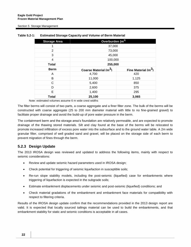
berms will tie into the contours of the mounded tailings piles at elevations ranging from 750 to 758 m. Table 5.2-
1 lists the estimated storage capacities and the required volumes of coarse aggregate and filter material for
each berm. The Haggart Creek IROSA will be capable of storing approximately 255,000 m3 of problematic ice-
rich material (i.e., Type IV), assuming an approximate 2% (50H:1V) gradient for the storage surface, with a
berm fill quantity of 28,000 m3. The storage volume could be increased substantially (~25% to 35%) if the ice-
rich material can be stacked behind the berms at slightly steeper grades (e.g., 15H:1V), or even more if the
tailings mounds along the western side of the IROSA were re-configured and re-shaped into a single berm
connecting the four storage cells.
Eagle Gold Project
Frozen Material Management Plan
Section 5 Storage Management
22
Table 5.2-1: Estimated Storage Capacity and Volume of Berm Material
Storage Area Overburden (m3)
1 37,000
2 73,000
3 45,000
4 100,000
Total 255,000
Berm Coarse Material (m3) Fine Material (m3)
A 4,700 420
B 11,000 1,125
C 5,400 850
D 2,600 375
E 1,400 295
Total 25,100 3,065
Note: estimated volumes assume 6 m wide crest widths
The filter berms will consist of two parts, a coarse aggregate and a finer filter zone. The bulk of the berms will be
constructed with coarse aggregate (25 to 200 mm diameter material with little to no fine-grained gravel) to
facilitate proper drainage and avoid the build-up of pore water pressure in the berm.
The containment berm and the storage area’s foundation are relatively permeable, and are expected to promote
drainage of the thawing stored materials. Silt and clay found at the base of the berms will be relocated to
promote increased infiltration of excess pore water into the subsurface and to the ground water table. A 2m wide
granular filter, comprised of well graded sand and gravel, will be placed on the storage side of each berm to
prevent migration of fines through the berm.
5.2.3 Design Update
The 2013 IROSA design was reviewed and updated to address the following items, mainly with respect to
seismic considerations:
Review and update seismic hazard parameters used in IROSA design;
Check potential for triggering of seismic liquefaction in susceptible soils;
Re-run slope stability models, including the post-seismic (liquefied) case for embankments where
triggering of liquefaction is expected in the subgrade soils;
Estimate embankment displacements under seismic and post-seismic (liquefied) conditions; and
Check material gradations of the embankment and embankment face materials for compatibility with
respect to filtering criteria.
Results of the IROSA design update confirm that the recommendations provided in the 2013 design report are
valid. It is expected that locally sourced tailings material can be used to build the embankments, and that
embankment stability for static and seismic conditions is acceptable in all cases.
Eagle Gold Project
Frozen Material Management Plan
Section 5 Storage Management
23
However, potentially liquefiable soils have been identified in the vicinity of Embankment A and C, and there
could be some associated risk of embankment slope failure and/or large displacements, particularly for
embankments in the northern half of the IROSA. This risk has been mitigated as described in Section 5.2.5
Facility Construction.
More detail is provided in Appendix A for each of the individual embankments.
5.2.4 Design Criteria
As described NELPCo (2013) the IROSA will be designed, constructed and operated in accordance with the
Design Manual prepared for the British Columbia Mine Waste Rock Pile Research Committee (Piteau, 1991).
As noted in section 3.2, approximately 195,000 m3 (up to 255,000 m
3 assuming 15% swell and 15% for
contingency) of ice-rich fine grained soils may require containment at the IROSA. These materials may be
generated at rates of about 4,000 m3 per day under the worst conditions, although it is not practical to predict
the rate accurately. It is possible, that approximately 75% to 80% of the total can be expected to be generated
in the first year of construction.
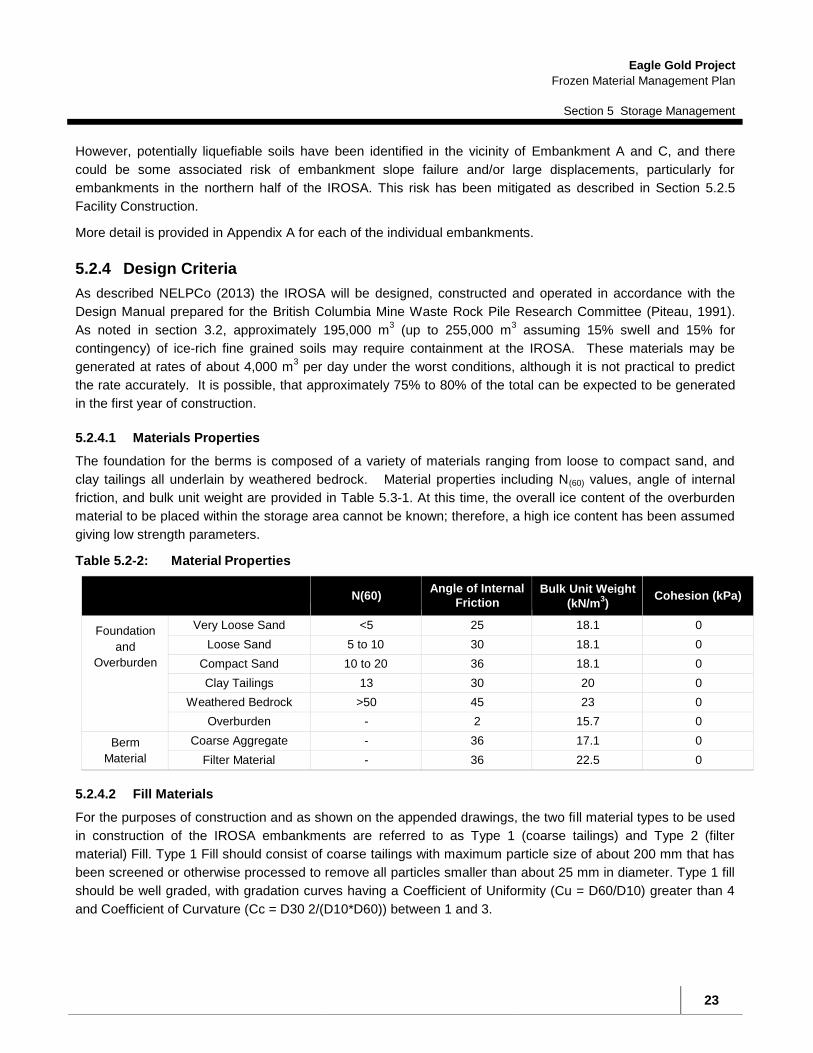
5.2.4.1 Materials Properties
The foundation for the berms is composed of a variety of materials ranging from loose to compact sand, and
clay tailings all underlain by weathered bedrock. Material properties including N(60) values, angle of internal
friction, and bulk unit weight are provided in Table 5.3-1. At this time, the overall ice content of the overburden
material to be placed within the storage area cannot be known; therefore, a high ice content has been assumed
giving low strength parameters.
Table 5.2-2: Material Properties
N(60)
Angle of Internal
Friction Bulk Unit Weight
(kN/m3)
Cohesion (kPa)
Foundation
and
Overburden
Very Loose Sand <5 25 18.1 0
Loose Sand 5 to 10 30 18.1 0
Compact Sand 10 to 20 36 18.1 0
Clay Tailings 13 30 20 0
Weathered Bedrock >50 45 23 0
Overburden - 2 15.7 0
Berm
Material Coarse Aggregate - 36 17.1 0
Filter Material - 36 22.5 0
5.2.4.2 Fill Materials
For the purposes of construction and as shown on the appended drawings, the two fill material types to be used
in construction of the IROSA embankments are referred to as Type 1 (coarse tailings) and Type 2 (filter
material) Fill. Type 1 Fill should consist of coarse tailings with maximum particle size of about 200 mm that has
been screened or otherwise processed to remove all particles smaller than about 25 mm in diameter. Type 1 fill
should be well graded, with gradation curves having a Coefficient of Uniformity (Cu = D60/D10) greater than 4
and Coefficient of Curvature (Cc = D30 2/(D10*D60)) between 1 and 3.

Eagle Gold Project
Frozen Material Management Plan
Section 5 Storage Management
24
More detail on the fill material properties is described in Section 4.2 of Appendix A.
5.2.4.3 Stability Assessment
Following the Design Manual, the selected ground motion parameters were based on an exceedence probability
of 10% in 50 years, which corresponds with a return period of 475 years, and a Peak Ground Acceleration
(PGA) of 0.14g.
The berm designs were analyzed by NELPCo (2013) assuming 1.3 factors of safety for the static condition and
1.0 factor of safety for the pseudostatic condition. These values were chosen based on the Design Manual
guidelines, and from presented ranges of values using past experience, the existing site conditions, and
material properties determined through site investigation and laboratory testing.
The storage area berms were evaluated assuming that fine-grained tailings were scraped off to expose the
berm foundation and enhance the effective draining of excess pore water pressure created by thawing ice-rich
overburden. Existing groundwater level readings taken during the geotechnical investigation were used in
determining pore water conditions for the stability analyses.
The overburden materials to be placed within the dump are considered to be ice-rich (Type IV). As the
overburden thaws this material could experience excess pore water pressure. For design purposes, a phreatic
surface was assumed to be at the surface of the overburden material, extending to the inner side of the filter
material where it decreases to the existing groundwater table below the base of the berm but into the
foundation material. Analyses also considered the potential of higher groundwater table rising to within the
foundation material to the base of the berm, although this scenario is considered unlikely.
Three failure modes were considered in the stability analysis: shallow seated, deep seated, and
psuedostatic failures. NELPCo found that shallow failures were the most probable failures on the
downstream and upstream faces. These failures are not considered to be critical to the stability of the design
provided the slumps are repaired promptly. NELPCo considered the deep seated failures to be of greater
concern, therefore, a deep seated critical slip surface that would have a larger impact on the stability of the
berm was analysed.
Stability was checked for both empty and full capacity cells. Stability analyses were completed for each berm.
All berms met or exceeded the minimum factor of safety recommended by the Design Manual.
As part of the Design Update, post-seismic slope stability was checked for each embankment where liquefaction
is expected to be triggered, with the zones of liquefied soil identified in the liquefaction triggering assessment
incorporated into the slope models and a reduced, post-seismic soil strength assigned to liquefied layers.
No horizontal seismic coefficient was applied in the post-seismic slope stability models (i.e., it is assumed that
the reduction in soil strength due to liquefaction occurs after the period of strong shaking during an earthquake).
Similar to the seismic slope stability assessment, stability at each embankment was considered for a variety of
cases (i.e., empty, full, partially full).
Results of post-seismic (liquefied) stability analyses are described for each embankment in Appendix A. In
summary, liquefiable layers were identified in the soil profiles for both Embankment A and C, but not in the other
embankments. The results suggest that the embankments would suffer significant stress due to liquefaction

Eagle Gold Project
Frozen Material Management Plan
Section 5 Storage Management
25
following the event of the design earthquake. However, these embankments are low risk structures and the
potential of failure is easily mitigated by the construction sequence, which is described below in Section 5.2.5.
5.2.4.4 Water Management
Controlling surface water run-off and groundwater is key in maintaining overall function of the IROSA.. Ensuring
that major surface water run-off sources are diverted from entering each storage cell, and that groundwater
does not buildup at and along the berm is critical to the overall stability of the storage area. To ensure that melt
water adequately drains through the storage berm and into the subsurface, the fine-grained silty tailings will be
scraped off the berm foundation, and coarse grained aggregate should be used for berm construction. Surface
water run off should be actively managed, if necessary, to minimize the amount of standing water collecting
within the storage area.
The historical diversion of Platinum Gulch freshet overflow should be decommissioned to prevent the freshet
flows from Platinum Gulch entering the IROSA. Further, the existing interceptor ditch located upslope of the
IROSA should be cleared and extended to the north, as much as feasible to divert non-contact runoff from
flowing to the south and away from the facility. These efforts will reduce the large majority of water from entering
the IROSA. An additional diversion ditch on the east side of the IROSA, will be built, if deemed practical and
necessary to intercept runoff from the small interfluvial upslope area, prior to loading of ice-rich material into the
IROSA.
Once the ice-rich material has been placed in storage to final grade, surface erosion and sediment control will
be required within the containment area. A roadside interceptor ditch draining to a small sediment basin may be
required downslope of the storage facility for collection of any water that might seep from the lowermost
containment berm. Pond outflow meeting discharge criteria would be directed towards Haggart Creek; if criteria
are not met, pond water would be pumped back to within the IROSA where it can later exfiltrate to groundwater.
Details of interceptor ditches and sediment control measures are discussed in the Construction & Operations
Water Management Plan.
It is expected that some water will enter the containment areas from time to time, in the form of surface runoff
and/or groundwater seepage from the forested slopes to the east (particularly during spring freshet), as
precipitation, and from thawing of ice-rich overburden soil stored in the IROSA. As such, to minimize
accumulation of water in the IROSA containment areas, waste overburden placed in the IROSA should be
graded to avoid ponding on top of fine-grained and/or other low permeability soils, and to encourage infiltration
of water into the embankments and/or exfiltrate into the ground.
Wherever freeboard for containment of surface runoff does not exist at any point around the perimeter of a filled
cell of the IROSA, suitable erosion control measures including (but not limited to) silt fencing will be established
such that sediment laden runoff from the cell is intercepted prior to flowing from the cell
The IROSA including containment berm toes have been sited to avoid encroaching into the Haggart Creek
floodplain, and are well back from the required 30 m offset of facilities (Figure 5.2-1).

Eagle Gold Project
Frozen Material Management Plan
Section 5 Storage Management
26
5.2.5 Facility Construction
5.2.5.1 Construction Sequence
Development of the IROSA will consist of the following main tasks:
Borrow development from placer tailings in the immediate area, including selection and processing of
engineering materials for the coarse aggregate berms and the upstream filter zones;
Foundation preparation, including leveling and relocating of existing organics, fine-grained materials or
other unsuitable materials within the footprint of the berm foundation, and excavation of key trenches,
as necessary;
Fill placement and compaction in lifts up to 1.5 m thick, including coincident placement of berm and
upstream filter materials;
Initial survey of completed berm for baseline deformation monitoring.
While each of these activities can be completed throughout most of the year, berm fill placement and
compaction will be completed during post-freshet and prior to freeze-up to minimize difficulties with watering and
compaction. Details of foundation preparation and embankment construction are described in NELPCo (2013).
The construction of the IROSA will be a staged process, with individual embankments and containment areas
built as and when required depending on volumes of ice-rich overburden material generated through the mine
life. The intent is to construct the northernmost embankments and containment areas first, to maximize the flow
path and filtering of water melting out of stored ice-rich overburden before reaching the sediment basin prior to
discharge to Haggart Creek. However, Embankments A and C were identified as being expected to experience
liquefaction of foundation soils under the design earthquake event, with likely consequences including damage
and/or failure of the embankment and possible release of stored overburden into the adjacent downgradient
containment area.
As such, to limit the potential for infiltration of sediment laden water from the IROSA, Embankments A and B are
to be constructed at the same time, such that Embankment B would be in place in the event of the design
earthquake to ensure that any sediment-rich overburden and/or meltwater is filtered before entering the
sediment basin prior to discharge to Haggart Creek. Similarly, Embankments D and E are to be constructed at
the same time as Embankment C. Under these conditions a release of stored overburden will not occur.
5.2.5.2 Transport and Disposal
Ice-rich materials will be hauled to and placed in the IROSA by dump truck. Ice-rich materials will not be placed
in any of the cells of the IROSA until the confining berm for that cell has been constructed.
Materials will be hauled immediately on excavation to minimize the time for thawing during handling, transport
and placement, and should be placed so as to thaw as much as possible to reduce swell and facilitate
conditioning for future reclamation. The stored materials may become soft on thawing. This phenomenon will
be more pronounced during summer and early fall when air temperatures are highest. Lifts of waste will be
graded gently, as feasible and practical depending on trafficability of the materials, toward the working edge to
promote drainage away from the stacked waste into temporary in-storage water collection areas within each
cell.

Eagle Gold Project
Frozen Material Management Plan
Section 5 Storage Management
27
5.2.5.3 IROSA Volume Management and Contingency Storage
SGC will conduct frequent (daily when adding material to a facility) monitoring which will include periodic
estimates of stockpile volumes. Standard construction management BMPs for maintaining visual inventory (or”
counting”) of truckloads, which will be complemented by periodic (i.e., monthly when facility is active) surveying
of storage facilities to check the volume and rate of filling of each storage facility will also be followed.
Further, the volume build-up in the IROSA will be monitored. Re-assessment of the remaining volume of ice rich
soil requiring engineered storage will be identified as being required at the earlier of 12 months from the start of
construction, or prior to the ice rich overburden storage area reaching 85% of its design capacity as required by
clause 136a of QZ14-041. Additional design capacity would be developed based on predicted additional
volume requirements associated with future construction activities. As stated above, the Haggart Creek IROSA
was selected because of the potential to continue to build additional capacity, up to 1,000,000 m3, as needed. It
will be highly unlikely, however, that the storage requirements would approach this volume.
Prior to the providing the additional design, a revised amount of the remaining Type IV and other types of ice
rich material still to be excavated and deemed to require engineered storage will be estimated. If the revised
estimate indicates that there is insufficient storage for expected ice-rich material then additional capacity at
at the Haggart Creek IROSA will be installed. This additional storage volume will consider a 15% contingency
plus an additional 15% for swell. The current plan calls for additional (or contingency) storage by increasing the
capacity at the Haggart Creek IROSA by incrementally increasing berm heights, which would ultimately join
some or all of the storage cells until the maximum capacity of the area is reached. Based on preliminary
estimates, this area could contain up to 1,000,000 m3.
5.2.5.4 Construction Quality Assurance and Quality Control
A construction quality assurance plan will be developed to ensure that the parameters used during the design
process are achieved. Elements to consider include:
Monitoring of fill material particle size distribution and placement;
Preparation of construction record drawings
The site development contractor will prepare a construction quality control plan, and to include, at a minimum,
the following components:
Inspection of foundation subgrades;
Inspection and testing of selected berm and upstream filter materials;
Regular accounting of volumes during fill placement and grading;
Daily inspections and photographic records of construction activities;
Photographs of the construction process at each stage of construction;
Oversight of installation of any required deformation monitoring targets;
Initial baseline survey for deformation monitoring; and

Eagle Gold Project
Frozen Material Management Plan
Section 5 Storage Management
28
Preparation of construction record drawings as a record of initial construction signed and sealed by a
professional engineer registered in the Yukon.
A detailed design report submitted to the Board at least 10 days prior to construction of any additional
storage capacity to be utilized.
5.2.6 Monitoring and Surveillance
The overall performance of the IROSA will be dependent on the physical stability of the berms. For a Class II
dump, the guidelines specify visual monitoring with basic instrumentation. Visual inspections will be completed
regularly to check for signs of instability including tension cracking, surficial sloughing, bulging, or
seepage zones along the downstream face of the berms.
A monitoring program will be designed, and implemented, and will include the following:
Regular visual inspection of the berms (crest and toe) looking for any signs of instability (cracking or
differential settlement) or erosion;
Regular visual inspection of the berm toes for any signs of seepage containing fine grained materials;
Installation of settlement pins for deformation monitoring after construction and initial survey of
completed berms for baseline deformation monitoring; and
Monitoring of settlement pins.
The results of the visual monitoring will provide insight into the physical performance of the filter berms over the
course of operations. In the event of instability, or poor performance (e.g. slumping of the crest, bulging of toe
areas, erosion), deformation monitoring of specific areas or remedial construction could be undertaken.
Prior to construction, water levels in the existing piezometers/wells will be read a sufficient number of times to
establish baseline ground water table conditions.
Visual inspections of the berms will be routinely conducted by technical personnel at the mine. More detailed
visual inspections will be conducted on a monthly basis by a competent person who has appropriate experience
and is familiar with the technical aspects of the containment berms design, construction, and monitoring.
Data from visual inspections and any more detailed deformation monitoring, if required, will be collected and
interpreted in an annual data report, with a detailed assessment and recommendations for monitoring and
remediation.
The IROSA will be monitored periodically as warranted by weather and use of the facility. Visual monitoring will
include inspection for tension cracking, sloughing, bulging, or seepages flows at the toe of the berm.
Groundwater levels will be monitored by piezometers installed prior to construction and use of the IORSA.
Survey points will be established on the crests of each berm which will be surveyed on a semi-annual basis to
monitor settlement or lateral movement. The frequency of monitoring will increase if significant movement is
identified.

Lynx Creek
EAGLEGOLD CAMP
H
a
g
g
a
r
t
C
r
e
e
k
R
o
a
d
HAGG
ERT
CRE
EK R
OAD
HAGG
ART
CREE
K
HAGG
ART
CREE
K
MW01
MW2
MW3
BH01
BH02
BH04
BH03
SA02(COARSEGRAINED)
MINE
ACC
ESS
ROAD
EMBANKMENT A(SEE FIGURE 2)
EMBANKMENT B(SEE FIGURE 3)
EMBANKMENT C(SEE FIGURE 4)
EMBANKMENT E(SEE FIGURE 6)
EMBANKMENT D(SEE FIGURE 5)
SA01 (FINE GRAINED)
TO E
AGLE
GOLD
CAM
P
TO HIGHWAY 11
CLIENT
PROJECT NO. DWN CKD REV
OFFICE DATE
Q:\W
hite
ho
rse
\D
ata
\0
20
1d
ra
win
gs\D
ub
lin
G
ulch
\E
NG
.W
AR
C0
32
35
-0
1 H
ag
ga
rt C
re
ek IR
OS
A D
esig
n U
pd
ate
\E
NG
.W
AR
C0
32
35
-0
1 F
ig
.1
-R
0.d
wg [F
IG
UR
E 1] Ju
ne
0
1, 2
01
7 - 1
:1
4:4
7 p
m (B
Y: B
UC
HA
N, C
AM
ER
ON
)
Figure 1May 29, 2017EBA-WHSE
0AWCB
STRATAGOLDCORPORATION
HAGGART CREEK ICE RICH OVERBURDEN STORAGE AREAEAGLE GOLD PROJECT - DUBLIN GULCH, YUKON
SITE PLAN SHOWING EMBANKMENT LOCATIONS
0
Scale: 1:25,000 @ 11"x17"
1,000m
LEGEND: - BORROW SOURCE SAMPLE LOCATION (2013 GEOTECHNICAL EVALUATION - W14103150-02)
- BOREHOLE LOCATION (2013 GEOTECHNICAL EVALUATION - W14103150-02) - MONITORING WELL LOCATION (2013 GEOTECHNICAL EVALUATION - W14103150-02) - APPROXIMATE EMBANKMENT FOOTPRINT - EXISTING DIVERSION DITCH ALIGNMENT
LOCATION PLAN0 200m
Scale: 1:4,000 @ 11"x17"
SITE PLAN
ISSUED FOR USE

Figure 5.1-2
EAGLE GOLD PROJECTYUKON TERRITORY
ICE-RICH MATERIALSMANAGEMENT PLAN
SUTTLES GULCH IOSA
NAD83UTM Zone 8
40 0 4020
Metres
Drawing to be read in conjunction with Management Plan for Ice-rich Materials dated April 2013
0DWLL PQ
FINAL April 2013
Eagle Gold
0792008-03-10
GF
GF
@A
ED
ED
ED
ED
ED
ED
ED
ED
ED
ED
ED
ED
ED
ED
ED
ED
ED
ED
ED
@A
@A@A
DIVERSIONCHANNEL
EL. 925 m
ROAD
925
920
915
930
910
905
900
895
935
890
945
885
880
950
875
870865
955
860
960
855
940
940
TP-BGC12-169
TP-BGC12-162
TP-BGC12-161
TP-BGC12-154
TP-BGC12-153
TP-BGC12-152
TP-BGC12-151
BH-BGC10-7
TP-BGC10-45
TP-BGC10-44
TP-BGC10-43
TP-BGC10-11
TP-BGC09-HL4-8
TP-BGC09-HL4-7
TP-BGC09-HL4-3
TP-BGC09-HL4-14
TP-BGC09-HL4-13
TP-BGC11-126
BH-BGC12-085
BH-BGC12-080
TP95-48
TP95-47
TP-B
459200
459200
459400
459400
7100
400
7100
400
7100
600
7100
600
±
NOTES
STATUS DATE
PROJECT
FILE NO.
PROJECTION
DWN
DATUM
OFFICE
CKD REV
CLIENT
APVDPROFESSIONAL SEAL
Scale: 1:2,500
LEGENDPROPOSED INFRASTRUCTURE LAYOUT
EXISTING ROAD
STREAM
@A BGC BOREHOLE
ED BGC TEST PIT
") BOREHOLE BY OTHERS
GF TESTPIT BY OTHERS
CONTAINMENT BERM
POTENTIAL STOREDICE-RICH MATERIALS
5 m CONTOUR
PRELIMINARY DESIGN.FOR INFORMATION ONLY.
SUBJECT TO CHANGE.NOT FOR CONSTRUCTION.
EAGLE GOLD PROJECTYUKON TERRITORY
1. Proposed infrastructure layout received from Wardrop March 28, 2012.
BG
C: X
:\Pro
ject
s\07
92 V
icto
ria G
old\
008\
Wor
kspa
ce\2
0130
108_
RE
PO
RT_
Ice_
Ric
h_M
ater
ials
_Man
agem
ent_
Pla
n\fig
_5_1
-2_S
uttle
s_G
ulch
_Opt
ion_
Loca
tion_
FIN
AL.
mxd
Figure 5.2-2
Suttles Gulch Ice-Rich Overburden Storage Area
Eagle Gold Project
Frozen Material Management Plan
Section 6 Reporting
31
6 REPORTING
An annual report will be prepared that will summarize management activities and field results from the
excavation, construction, transport, stockpiling, disposal and monitoring of frozen materials. Records of
monitoring shall include summaries of data generated as a result of the monitoring activities described herein,
including analysis and interpretation by a qualified individual or firm and a discussion of any variances from
baseline conditions, from the previous years’ data, or from expected performance, or variances from expected
conditions such as the volume of ice rich material.

Eagle Gold Project
Frozen Material Management Plan
Section 7 References
32
7 REFERENCES
BGC Engineering Inc 2013. Draft Ice-rich Materials Management Plan, version 2013-01, April 2013. BGC Engineering Inc. 2012a. 2011 Geotechnical Investigation for Mine Site Infrastructure – Factual Data Report, dated January 20, 2012. BGC Engineering Inc. 2012b. 2011 Geotechnical Investigation for Mine Site Infrastructure - Foundation Report, dated January 31, 2012. BGC Engineering Inc. 2012c. Estimate of Ice-rich Material, Project Memorandum prepared November 16, 2012 for Victoria Gold Corp. BGC Engineering Inc. 2011. 2010 Geotechnical Investigation for Mine Site Infrastructure – Factual Data Report, dated November 17, 2011. BGC Engineering Inc. 2010. 2009 Site Facilities Geotechnical Investigation Factual Data Report, dated March 5, 2010. CAN/BNQ 2501-500. 2017. Geotechnical Site Investigations for Building Foundations in Permafrost Zones. Standards Council of Canada, Available February 2017. Knight Piésold 1996a. Report on 1995 Geotechnical Investigations for Four Potential Heap Leach Facility Site Alternatives, First Dynasty Mines, Dublin Gulch Property. Knight Piésold 1996b. Report on Feasibility Design of the Mine Waste Rock Storage Area, First Dynasty Mines, Dublin Gulch Property. Piteau 1991. Investigation and Design Manual – Interim Guidelines; Investigation and Design of Mine Dumps, prepared for the BC Mine Waste Rock Pile Research Committee, by Piteau Associates Engineering, Ltd, May 1991. Sitka Corp. 1996. Field Investigation Data Report, Dublin Gulch Project, New Millennium Mining.

Eagle Gold Project
2016 Annual Report(includes ice-rich and non ice-rich permafrost)
Appendix A Geotechnical Design Update and IFC Drawings
APPENDIX A Geotechnical Design Update and IFC Drawings

THIS PAGE INTENTIONALLY LEFT BLANK

Tetra Tech Canada Inc. 61 Wasson Place
Whitehorse, YT Y1A 0H7 CANADA Tel 867.668.3068 Fax 867.668.4349
June 8, 2017 ISSUED FOR USE FILE: ENG.WARC03235-01 JDS Energy and Mining Inc. Via Email: [email protected] 206 – 3200 Richter Street Kelowna, BC V1W 5K9 Attention: Kevin Mather, President
Subject: Geotechnical Design Update and IFC Drawings
Haggart Creek Ice-Rich Overburden Storage Area Eagle Gold Project – Dublin Gulch, YT
1.0 INTRODUCTION
NND-EBA Land Protection Corporation, operating as NELPCo Limited Partnership (NELPCo) was retained by JDS Energy and Mining Inc. (JDS), on behalf of StrataGold Corporation (StrataGold), to review the existing design and prepare drawings for construction of a proposed Ice-Rich Overburden Storage Area (IROSA) at StrataGold’s Eagle Gold Project, located at Dublin Gulch, YT.
NELPCo is an aboriginal company that is majority owned by the Na-Cho Nyak Dun Development Corporation, in partnership with Tetra Tech Canada Inc. (Tetra Tech), NELPCo’s exclusive engineering service provider, which has
completed the scope of work described herein.
IROSA facilities at the Eagle Gold Project are intended to be used for storage and disposal of waste overburden material, including ice-rich permafrost, which is expected to be produced during construction of the Eagle Gold Mine.
The Haggart Creek IROSA is located in an area of tailings produced during historical placer mining activity, on the east side of Haggart Creek and the existing mine access road and about 2 km south of the mine camp.
A preliminary geotechnical design for the Haggart Creek IROSA was developed in 2013 by Tetra Tech (operating as EBA, a Tetra Tech Company), and a geotechnical design report (Geotechnical Design – Ice-Rich Overburden
Storage Area Berms – Eagle Gold Property, Yukon Territories, File No. W14103150-02) was prepared and submitted to StrataGold, via NELPCo, in December 2013.
The purpose of Tetra Tech’s current scope of work is to review and update the existing IROSA design, and prepare Issued for Construction (IFC) drawings for construction of the IROSA facility berms. This report serves as a covering letter for transmittal of the IFC drawing package, and summarizes the work completed to update and revise the 2013 design.
IFC drawings are attached to this report in Appendix C.
2.0 2013 IROSA DESIGN
The 2013 IROSA design report provided recommendations for construction of five embankments, defining four containment areas located within a series of existing depressions in an area of old placer mine tailings, for storage of ice-rich waste overburden. The embankments were located to separate the various containment areas from one

EAGLE GOLD PROJECT - HAGGART CREEK IROSA – DESIGN UPDATE AND IFC DRAWINGS FILE: ENG.WARC03235-01 | JUNE 8, 2017 | ISSUED FOR USE
2 ENGWARC03235-01_Haggart Creek IROSA Design Update
another and from exterior areas outside of the IROSA, and designed in accordance with the guidelines set forth in the 1991 Mined Rock and Overburden Piles Investigation and Design Manual, published by the BC Mine Waste Rock Pile Research Committee.
Tetra Tech completed a geotechnical drilling program at the site, to assess the subsurface conditions and collect geotechnical information that was used to check the stability of the proposed embankments under post-construction (empty), operating (full) and seismic (pseudostatic) conditions. Triggering of liquefaction in layers of sandy soil encountered in the drilling investigation was noted as a possible area of concern, but was not checked in detail at that time.
The IROSA embankments were to be constructed using locally sourced tailings material, consisting of highly permeable, coarse material (particle gradation between 25 and 200 mm diameter) for the bulk of the embankment, with a layer of finer tailings material (75 mm minus gravel) on the embankment face to act as a filter between the coarse embankment fill and the fine-grained overburden. The embankment face would be sloped at 2H:1V.
As described in the 2013 design report, the Haggart Creek IROSA was considered to satisfy the applicable design guidelines, and would provide a storage area for about 255,000 m3 of waste overburden material.
The 2013 report is attached for reference in Appendix B. In general, the recommendations contained therein are considered to remain valid for the design and construction of the IROSA, with the exception of items described below in Sections 3 and 4; where there is conflict between the two documents, recommendations in this report will supercede those provided in the 2013 design.
3.0 SUMMARY OF DESIGN UPDATE
As described in NELPCo’s proposal, the 2013 IROSA design was reviewed and updated to address the following items, mainly with respect to seismic considerations:
Review and update seismic hazard parameters used in IROSA design;
Check potential for triggering of seismic liquefaction in susceptible soils;
Re-run slope stability models, including the post-seismic (liquefied) case for embankments where triggering of liquefaction is expected in the subgrade soils;
Estimate embankment displacements under seismic and post-seismic (liquefied) conditions; and
Check material gradations of the embankment and embankment face materials for compatibility with respect to filtering criteria.
3.1 Seismic Hazard Parameters
The 1991 Design Guidelines specify that waste dumps/piles should be designed to withstand a seismic event with an annual probability of exceedance of 10% in 50 years (i.e., 1:475 year earthquake). The 1:475 year event was commonly used in several design codes, such as the National Building Code of Canada (NBCC), at the time these guidelines were published; however, in recent times (e.g., NBCC since 2005) design standards have required consideration of more severe earthquake events, typically with annual probability of exceedance of 2% in 50 years (i.e., 1:2,475 year earthquake).
For certain structures (e.g., large dams), design guidelines stipulate that more severe seismic events must be considered, such as the 1:10,000 year earthquake, or the Maximum Credible Earthquake (MCE), which is a

EAGLE GOLD PROJECT - HAGGART CREEK IROSA – DESIGN UPDATE AND IFC DRAWINGS FILE: ENG.WARC03235-01 | JUNE 8, 2017 | ISSUED FOR USE
3 ENGWARC03235-01_Haggart Creek IROSA Design Update
deterministic (rather than probabilistic) representation of the most severe seismic event likely to occur at a given site, based on knowledge of the surrounding tectonic setting.
For the IROSA embankments, which are considered to not have a major consequence of failure, the 475 year earthquake is considered to be appropriate for design, as recommended in the 1991 Guidelines. As such, the IROSA design considered the site seismic hazard from the 2015 edition of the NBCC, as generated by Natural Resources Canada’s (NRC) seismic hazard calculator, available online at: http://www.earthquakescanada.nrcan.gc.ca/index-en.php.
While the 475 year earthquake is considered to be the “design” event for this project, the online calculator output
also includes seismic hazard for the 2,475 year earthquake (current NBCC design earthquake), and an estimate of hazard (PGA and moment magnitude) due to the MCE event is available in a Technical Memorandum (Tetra Tech 2012) prepared for StrataGold’s parent company, Victoria Gold Corporation. As such, both of these hazard levels were also checked in the liquefaction triggering and embankment stability analyses, to estimate the potential damage that may be associated with more severe earthquake events.
All seismic analyses described below considered an amplified Peak Ground Acceleration (PGA) reflecting Site Class D conditions, per NBCC 2015. Generation of an amplified acceleration spectrum for the MCE event was estimated by linear scaling of the NBCC uniform hazard spectrum for the 2,475 year event to match the PGA provided for the MCE, and amplification factors were then applied per the routine NBCC procedure. Scaling in this way is considered to provide only a crude approximation of the acceleration spectrum, however it may still be reasonable for use in estimating impacts of the MCE to the IROSA embankments.
Earthquake magnitudes used in the liquefaction triggering assessment were the mean magnitude from a de-aggregation of the NBCC seismic hazard, provided by NRC, and the magnitude recommended in Tetra Tech’s 2012
memo for the MCE event.
3.2 Liquefaction Triggering
Seismic liquefaction can occur when loose, saturated, sandy soil is subjected to cyclic shear stresses during an earthquake, and is characterized by a rapid rise in the soil porewater pressure and a corresponding rapid loss in soil strength and stiffness. Seismic liquefaction is commonly accompanied by vertical and horizontal displacements on level ground, and slope failures in areas with topographic relief.
Sand and silt layers encountered on the site, including both native soils and tailings material, are potentially susceptible to seismic liquefaction. As such, liquefaction triggering was checked according to the simplified procedures described by Idriss and Boulanger (2008), for the 475 year, 2,475 year, and MCE events, using the SPT N-values and groundwater conditions encountered during the 2013 drilling program.
Because only one borehole was drilled in the vicinity of each embankment, the liquefaction triggering analysis in each case is based on the soil profile and SPT N-values encountered in that single borehole; for the purposes of checking post-seismic embankment stability and estimating post-seismic displacement, liquefiable layers encountered in each borehole are assumed to be continuous within the vicinity of the corresponding embankment.
Results of the liquefaction triggering analysis for each embankment are provided in Section 4.
3.3 Embankment Slope Stability
Slope stability models were re-checked using Slope/W software, to account for the updated seismic design criteria and to check stability of embankments in the event of liquefaction.

EAGLE GOLD PROJECT - HAGGART CREEK IROSA – DESIGN UPDATE AND IFC DRAWINGS FILE: ENG.WARC03235-01 | JUNE 8, 2017 | ISSUED FOR USE
4 ENGWARC03235-01_Haggart Creek IROSA Design Update
For embankments A, B and C, which are bounded on both sides by containment areas, various scenarios were checked with respect to the influence that the sequence of overburden placement on either side of the embankment might have on embankment stability.
Minimum Factors of Safety (FS) of 1.5 and 1.0 were targeted for static and seismic (pseudostatic and post-seismic) conditions, respectively.
Results of the slope stability assessment for each embankment are discussed in Section 4.
3.3.1 Static Conditions
Slope stability under static conditions was checked for each of the embankments. A variety of operating conditions were assessed, including with empty containment areas (i.e., free standing embankment with no surrounding overburden), full containment areas (i.e., containment area full on the north, south, or both sides of the embankment) and partially full containment areas (i.e., various combinations with partially full containment areas on one or both sides of the embankments).
3.3.2 Seismic (Pseudostatic) Conditions
Seismic slope stability for each embankment was checked for the 475 year, 2,475 year and MCE events using the pseudostatic approach, where the seismic inertial force affecting the embankment is represented as a static horizontal force, defined as a horizontal seismic coefficient (as a proportion of gravitational force). In all cases, a horizontal seismic coefficient equal to 50% of PGA, scaled for Site Class D, was used.
For each embankment, the same range of operating conditions from the static load case (i.e., empty, full, partially full) was checked.
3.3.3 Post-Seismic (Liquefied) Conditions
Post-seismic slope stability was checked for each embankment where liquefaction is expected to be triggered, with the zones of liquefied soil identified in the liquefaction triggering assessment incorporated into the slope models and a reduced, post-seismic soil strength assigned to liquefied layers.
No horizontal seismic coefficient was applied in the post-seismic slope stability models (i.e., it is assumed that the reduction in soil strength due to liquefaction occurs after the period of strong shaking during an earthquake).
Similar to the seismic slope stability assessment, stability at each embankment was considered for a variety of cases (i.e., empty, full, partially full).
3.4 Estimated Seismic and Post-Seismic Displacement
Seismic displacements, caused directly by shaking during an earthquake, were estimated for each embankment and each seismic event following the method described by Bray and Travasarou (2007). Seismic yield accelerations were determined for each embankment using Slope/W software, and spectral acceleration at a period (T) of zero seconds (adjusted for Site Class D conditions) was used in the displacement calculation; due to the characteristic shape of NBCC hazard spectra, using spectral acceleration at T = 0 s will be equivalent or conservative compared to using the spectral acceleration at 1.5x the natural period of the embankment, as recommended by Bray and Travasarou.
Post-seismic displacement at ground surface, caused by lateral shear and vertical reconsolidation strain in liquefied layers, was estimated using the simplified procedures described by Idriss and Boulanger (2008). Lateral displacements estimated using this method are generated through cumulative summation of shear strains estimated
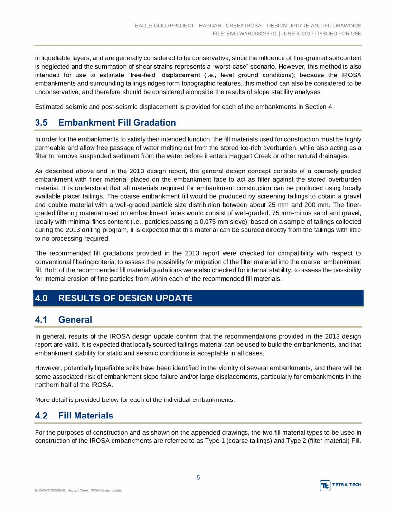
EAGLE GOLD PROJECT - HAGGART CREEK IROSA – DESIGN UPDATE AND IFC DRAWINGS FILE: ENG.WARC03235-01 | JUNE 8, 2017 | ISSUED FOR USE
5 ENGWARC03235-01_Haggart Creek IROSA Design Update
in liquefiable layers, and are generally considered to be conservative, since the influence of fine-grained soil content is neglected and the summation of shear strains represents a “worst-case” scenario. However, this method is also intended for use to estimate “free-field” displacement (i.e., level ground conditions); because the IROSA embankments and surrounding tailings ridges form topographic features, this method can also be considered to be unconservative, and therefore should be considered alongside the results of slope stability analyses.
Estimated seismic and post-seismic displacement is provided for each of the embankments in Section 4.
3.5 Embankment Fill Gradation
In order for the embankments to satisfy their intended function, the fill materials used for construction must be highly permeable and allow free passage of water melting out from the stored ice-rich overburden, while also acting as a filter to remove suspended sediment from the water before it enters Haggart Creek or other natural drainages.
As described above and in the 2013 design report, the general design concept consists of a coarsely graded embankment with finer material placed on the embankment face to act as filter against the stored overburden material. It is understood that all materials required for embankment construction can be produced using locally available placer tailings. The coarse embankment fill would be produced by screening tailings to obtain a gravel and cobble material with a well-graded particle size distribution between about 25 mm and 200 mm. The finer-graded filtering material used on embankment faces would consist of well-graded, 75 mm-minus sand and gravel, ideally with minimal fines content (i.e., particles passing a 0.075 mm sieve); based on a sample of tailings collected during the 2013 drilling program, it is expected that this material can be sourced directly from the tailings with little to no processing required.
The recommended fill gradations provided in the 2013 report were checked for compatibility with respect to conventional filtering criteria, to assess the possibility for migration of the filter material into the coarser embankment fill. Both of the recommended fill material gradations were also checked for internal stability, to assess the possibility for internal erosion of fine particles from within each of the recommended fill materials.
4.0 RESULTS OF DESIGN UPDATE
4.1 General
In general, results of the IROSA design update confirm that the recommendations provided in the 2013 design report are valid. It is expected that locally sourced tailings material can be used to build the embankments, and that embankment stability for static and seismic conditions is acceptable in all cases.
However, potentially liquefiable soils have been identified in the vicinity of several embankments, and there will be some associated risk of embankment slope failure and/or large displacements, particularly for embankments in the northern half of the IROSA.
More detail is provided below for each of the individual embankments.
4.2 Fill Materials
For the purposes of construction and as shown on the appended drawings, the two fill material types to be used in construction of the IROSA embankments are referred to as Type 1 (coarse tailings) and Type 2 (filter material) Fill.

EAGLE GOLD PROJECT - HAGGART CREEK IROSA – DESIGN UPDATE AND IFC DRAWINGS FILE: ENG.WARC03235-01 | JUNE 8, 2017 | ISSUED FOR USE
6 ENGWARC03235-01_Haggart Creek IROSA Design Update
Type 1 Fill should consist of coarse tailings with maximum particle size of about 200 mm that has been screened or otherwise processed to remove all particles smaller than about 25 mm in diameter. Type 1 fill should be well graded, with gradation curves having a Coefficient of Uniformity (Cu = D60/D10) greater than 4 and Coefficient of Curvature (Cc = D302/(D10*D60)) between 1 and 3.
The recommended gradation for Type 2 Fill is provided on Table 4.2-1 below:
Table 4.2-1: Recommended Gradation for Type 2 Fill Particle Size (mm) Percent Finer (% by weight)
75 100 25 65 – 100
12.5 45 – 85 4.75 25 – 70
0.825 5 – 30 0.425 0 – 20 0.163 0 – 15 0.075 0 – 10
The recommended gradation of Type 2 Fill has been modified slightly from that provided in the 2013 report. The gradation curve for the sample of proposed filter material that was recovered and tested during the 2013 drilling program still conforms to the gradation specified above, however it falls at approximately the fine limit of the specified gradation band; i.e., unprocessed tailings available on-site may be generally suitable for use as Type 2 Fill, however coarser material compared to the sample recovered in 2013 is desirable for increased permeability and drainage of meltwater through the embankment face.
Both of the material types described above are considered to be internally stable. However, the difference in gradation between Type 1 and Type 2 Fill is too great for the materials to effectively filter one another; i.e., there is a risk that the fine portion of the Type 2 Fill would be washed into the larger voids in the adjacent Type 1 Fill as water seeps through the embankment. As such, a layer of geotextile filter fabric should be installed between Type 1 and Type 2 fill. The geotextile will also help to remove suspended fine soil particles compared to the granular filtering action alone.
Alternatively, a multi-layer granular filter could be used, however this would require more material processing to produce fill for multiple filtering layers, and would also be more complex with respect to fill placement for embankment construction.
4.3 Embankment A
As noted in Section 4.1, embankment stability meets applicable target FS for static operating conditions (target FS = 1.5), as well as seismic (pseudostatic, target FS = 1.0) conditions for the design 475 year earthquake, as well as the larger 2,475 year and MCE events.
Median seismic displacement estimated using the Bray and Travasarou method is 1.6 cm for the 475 year earthquake, and 6.0 and 11.2 cm for the 2,475 year and MCE events, respectively. It is expected that seismic displacement caused by each of these earthquake events can be sustained with minimal distress to the embankment.

EAGLE GOLD PROJECT - HAGGART CREEK IROSA – DESIGN UPDATE AND IFC DRAWINGS FILE: ENG.WARC03235-01 | JUNE 8, 2017 | ISSUED FOR USE
7 ENGWARC03235-01_Haggart Creek IROSA Design Update
However, liquefiable layers were identified in the soil profile encountered in BH04, as shown on Table 4.3-1 below. Note that depths shown on the table are measured from ground surface at the applicable borehole location, and not from the embankment crest.
Table 4.3-1: Liquefaction at Embankment A (2013 BH04) Parameter 475 year EQ 2,475 Year EQ MCE
Depth Range of Liquefiable Soil (m bgs) 2.5 – 5.5 1.5 – 7.7 1.5 – 7.7 Estimated Free-Field Lateral Displacement (m) 1.1 2.2 2.2
Estimated Vertical Settlement (mm) 70 205 205
Based on the slope stability modeling of Embankment A, with a reduced soil strength applied to liquefied layers, post-seismic stability may be greater than the target FS of 1.0 when the containment areas on both sides are filled to within about 3 m of the crest, due to the buttressing effect of the overburden material. However, under most operating conditions the FS for embankment slope stability falls below 1.0 for each of the considered earthquake events, including the design (475 year) event.
Combined with the relatively large estimated displacements shown on Table 4.3-1, the post-seismic FS of less than 1.0 implies that the embankment would suffer significant distress due to liquefaction following an earthquake, including several hundred millimetres of vertical settlement and lateral displacement on the order of several metres; it is likely that Embankment A would require major repair and/or complete reconstruction in the event of the design earthquake.
4.4 Embankment B
As noted in Section 4.1, embankment stability meets applicable target FS for static operating conditions (target FS = 1.5), as well as seismic (pseudostatic, target FS = 1.0) conditions for the design 475 year earthquake, as well as the larger 2,475 year and MCE events.
Median seismic displacement estimated using the Bray and Travasarou method is 1.6 cm for the 475 year earthquake, and 6.0 and 11.2 cm for the 2,475 year and MCE events, respectively. It is expected that seismic displacement caused by each of these earthquake events can be sustained with minimal distress to the embankment.
Furthermore, based on the soil profile encountered in BH03, no liquefaction is expected under the design earthquake event. However, liquefiable soils were identified for more severe earthquake events, as shown on Table 4.4-1 below. Note that depths shown on the table are measured from ground surface at the applicable borehole location, and not from the embankment crest.
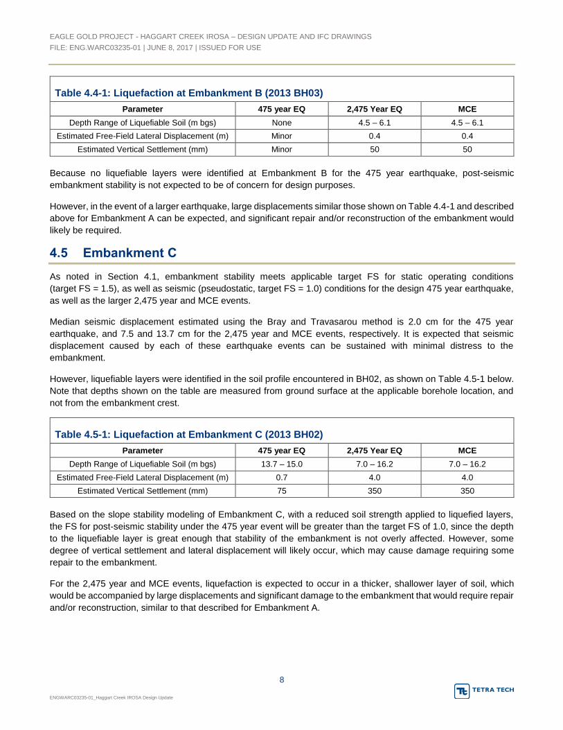
EAGLE GOLD PROJECT - HAGGART CREEK IROSA – DESIGN UPDATE AND IFC DRAWINGS FILE: ENG.WARC03235-01 | JUNE 8, 2017 | ISSUED FOR USE
8 ENGWARC03235-01_Haggart Creek IROSA Design Update
Table 4.4-1: Liquefaction at Embankment B (2013 BH03) Parameter 475 year EQ 2,475 Year EQ MCE
Depth Range of Liquefiable Soil (m bgs) None 4.5 – 6.1 4.5 – 6.1 Estimated Free-Field Lateral Displacement (m) Minor 0.4 0.4
Estimated Vertical Settlement (mm) Minor 50 50
Because no liquefiable layers were identified at Embankment B for the 475 year earthquake, post-seismic embankment stability is not expected to be of concern for design purposes.
However, in the event of a larger earthquake, large displacements similar those shown on Table 4.4-1 and described above for Embankment A can be expected, and significant repair and/or reconstruction of the embankment would likely be required.
4.5 Embankment C
As noted in Section 4.1, embankment stability meets applicable target FS for static operating conditions (target FS = 1.5), as well as seismic (pseudostatic, target FS = 1.0) conditions for the design 475 year earthquake, as well as the larger 2,475 year and MCE events.
Median seismic displacement estimated using the Bray and Travasarou method is 2.0 cm for the 475 year earthquake, and 7.5 and 13.7 cm for the 2,475 year and MCE events, respectively. It is expected that seismic displacement caused by each of these earthquake events can be sustained with minimal distress to the embankment.
However, liquefiable layers were identified in the soil profile encountered in BH02, as shown on Table 4.5-1 below. Note that depths shown on the table are measured from ground surface at the applicable borehole location, and not from the embankment crest.
Table 4.5-1: Liquefaction at Embankment C (2013 BH02) Parameter 475 year EQ 2,475 Year EQ MCE
Depth Range of Liquefiable Soil (m bgs) 13.7 – 15.0 7.0 – 16.2 7.0 – 16.2 Estimated Free-Field Lateral Displacement (m) 0.7 4.0 4.0
Estimated Vertical Settlement (mm) 75 350 350
Based on the slope stability modeling of Embankment C, with a reduced soil strength applied to liquefied layers, the FS for post-seismic stability under the 475 year event will be greater than the target FS of 1.0, since the depth to the liquefiable layer is great enough that stability of the embankment is not overly affected. However, some degree of vertical settlement and lateral displacement will likely occur, which may cause damage requiring some repair to the embankment.
For the 2,475 year and MCE events, liquefaction is expected to occur in a thicker, shallower layer of soil, which would be accompanied by large displacements and significant damage to the embankment that would require repair and/or reconstruction, similar to that described for Embankment A.
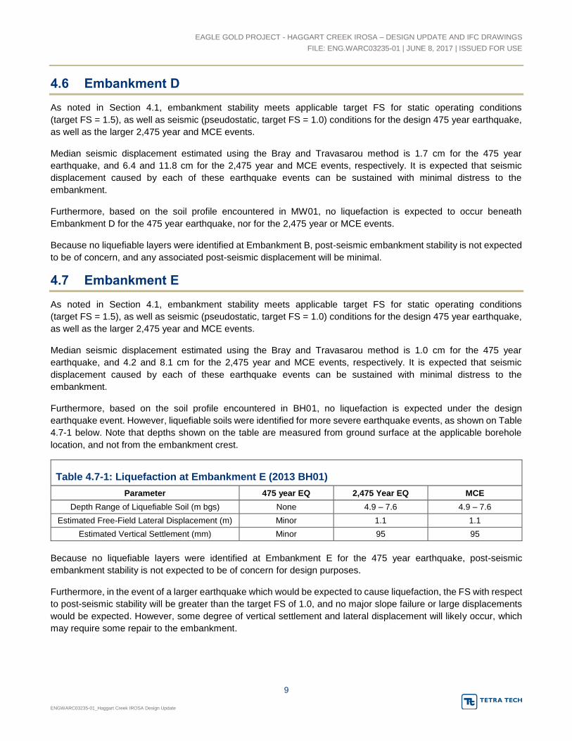
EAGLE GOLD PROJECT - HAGGART CREEK IROSA – DESIGN UPDATE AND IFC DRAWINGS FILE: ENG.WARC03235-01 | JUNE 8, 2017 | ISSUED FOR USE
9 ENGWARC03235-01_Haggart Creek IROSA Design Update
4.6 Embankment D
As noted in Section 4.1, embankment stability meets applicable target FS for static operating conditions (target FS = 1.5), as well as seismic (pseudostatic, target FS = 1.0) conditions for the design 475 year earthquake, as well as the larger 2,475 year and MCE events.
Median seismic displacement estimated using the Bray and Travasarou method is 1.7 cm for the 475 year earthquake, and 6.4 and 11.8 cm for the 2,475 year and MCE events, respectively. It is expected that seismic displacement caused by each of these earthquake events can be sustained with minimal distress to the embankment.
Furthermore, based on the soil profile encountered in MW01, no liquefaction is expected to occur beneath Embankment D for the 475 year earthquake, nor for the 2,475 year or MCE events.
Because no liquefiable layers were identified at Embankment B, post-seismic embankment stability is not expected to be of concern, and any associated post-seismic displacement will be minimal.
4.7 Embankment E
As noted in Section 4.1, embankment stability meets applicable target FS for static operating conditions (target FS = 1.5), as well as seismic (pseudostatic, target FS = 1.0) conditions for the design 475 year earthquake, as well as the larger 2,475 year and MCE events.
Median seismic displacement estimated using the Bray and Travasarou method is 1.0 cm for the 475 year earthquake, and 4.2 and 8.1 cm for the 2,475 year and MCE events, respectively. It is expected that seismic displacement caused by each of these earthquake events can be sustained with minimal distress to the embankment.
Furthermore, based on the soil profile encountered in BH01, no liquefaction is expected under the design earthquake event. However, liquefiable soils were identified for more severe earthquake events, as shown on Table 4.7-1 below. Note that depths shown on the table are measured from ground surface at the applicable borehole location, and not from the embankment crest.
Table 4.7-1: Liquefaction at Embankment E (2013 BH01) Parameter 475 year EQ 2,475 Year EQ MCE
Depth Range of Liquefiable Soil (m bgs) None 4.9 – 7.6 4.9 – 7.6 Estimated Free-Field Lateral Displacement (m) Minor 1.1 1.1
Estimated Vertical Settlement (mm) Minor 95 95
Because no liquefiable layers were identified at Embankment E for the 475 year earthquake, post-seismic embankment stability is not expected to be of concern for design purposes.
Furthermore, in the event of a larger earthquake which would be expected to cause liquefaction, the FS with respect to post-seismic stability will be greater than the target FS of 1.0, and no major slope failure or large displacements would be expected. However, some degree of vertical settlement and lateral displacement will likely occur, which may require some repair to the embankment.

EAGLE GOLD PROJECT - HAGGART CREEK IROSA – DESIGN UPDATE AND IFC DRAWINGS FILE: ENG.WARC03235-01 | JUNE 8, 2017 | ISSUED FOR USE
10 ENGWARC03235-01_Haggart Creek IROSA Design Update
5.0 GEOTECHNICAL RECOMMENDATIONS FOR IROSA OPERATION
5.1 Water Management
The IROSA embankments and containment areas are not intended to be used as water retaining structures, and have not been designed as such.
Surface water management will be an important consideration during operation of the IROSA. During a visit to the site completed by Tetra Tech, JDS and StrataGold in May 2017, a stream descending from Platinum Gulch was observed spilling into the northeast corner of the Haggart Creek IROSA; based on discussion during the site visit, we understand that this stream will be diverted away from the IROSA and towards a proposed collection pond as part of the site’s overall water management plan.
At the time of the site visit, no other significant streams were observed entering the IROSA area, however any other streams or concentrated flows noted in the future should be diverted away from the IROSA containment areas, similar to the stream emanating from Platinum Gulch.
It is also expected that water will enter the containment areas from time to time, in the form of surface runoff and/or groundwater seepage from the forested slopes to the east (particularly during spring freshet), as precipitation, and from thawing of ice-rich overburden soil stored in the IROSA.
As such, to minimize accumulation of water in the IROSA containment areas, waste overburden placed in the IROSA should be graded to avoid ponding on top of fine-grained and/or other low permeability soils, and to encourage infiltration of water into the embankments and/or other areas of similarly permeable tailings.
5.2 Sequence of IROSA Embankment Construction
Tetra Tech understands that construction of the IROSA facility will be a staged process, with individual embankments and containment areas built as and when required depending on volumes of ice-rich overburden material generated through the mine life.
It is also understood that the intent is to construct the northernmost embankments and containment areas first, to maximize the flow path and filtering of water melting out of stored ice-rich overburden before reaching Haggart Creek. However, Embankments A and C were identified as being expected to experience liquefaction of foundation soils under the design earthquake event, with likely consequences including damage and/or failure of the embankment and possible release of stored overburden into the adjacent downstream containment area.
As such, to satisfy applicable water license requirements limiting infiltration of sediment laden water into Haggart Creek from the IROSA, it is recommended that Embankments A and B are constructed at the same time, such that Embankment B would be in place to ensure that any sediment-rich overburden or meltwater does not reach Haggart Creek in the event of the design earthquake. Similarly, it is recommended that Embankments D and E are constructed at the same time as Embankment C.
5.3 Survey and Monitoring Requirements
Monitoring requirements during IROSA operation were discussed in the 2013 report. These include:
Regular visual inspection of the embankment condition, to check for distress in the embankments including cracking, sloughing, slumping, toe bulging, etc.

EAGLE GOLD PROJECT - HAGGART CREEK IROSA – DESIGN UPDATE AND IFC DRAWINGS FILE: ENG.WARC03235-01 | JUNE 8, 2017 | ISSUED FOR USE
11 ENGWARC03235-01_Haggart Creek IROSA Design Update
Regular visual inspection of surface water conditions in the IROSA containment areas.
Regular visual inspection of surface water and seepage entering the IROSA from surrounding areas, particularly the natural slopes to the east.
Survey monuments should be established along the crest of each embankment and regularly monitored to track lateral and vertical settlement. Monuments should be surveyed nominally twice a year (spring freshet and fall freeze-up) during routine operations, and more frequently in the event that ongoing movement is noted or “extreme” operating conditions are present (e.g., earthquake, high volumes of ponded water entering IROSA).
If desired, monitoring wells can be installed in the embankments to allow for water quality sampling.
6.0 LIMITATIONS OF REPORT
This report and its contents are intended for the sole use of StrataGold Corporation and their agents, including JDS Energy and Mining Inc. Tetra Tech Canada Inc. (operating as Tetra Tech) does not accept any responsibility for the accuracy of any of the data, the analysis, or the recommendations contained or referenced in the report when the report is used or relied upon by any Party other than StrataGold Corporation, or for any Project other than the proposed development at the subject site. Any such unauthorized use of this report is at the sole risk of the user. Use of this report is subject to the terms and conditions stated in Tetra Tech Canada Inc.’s Services Agreement. Tetra Tech’s General Conditions are provided in Appendix A of this report.

EAGLE GOLD PROJECT - HAGGART CREEK IROSA – DESIGN UPDATE AND IFC DRAWINGS FILE: ENG.WARC03235-01 | JUNE 8, 2017 | ISSUED FOR USE
12 ENGWARC03235-01_Haggart Creek IROSA Design Update
7.0 CLOSURE
We trust this report meets your present requirements. If you have any questions or comments, please contact the undersigned.
Respectfully submitted, Tetra Tech Canada Inc. Prepared by: Reviewed by: Adam Wallace, M.Eng., P.Eng. Chad Cowan, P.Eng. Geotechnical Engineer, Arctic Group Whitehorse Geotechnical Manager, Arctic Group Direct Line: 867.668.9218 Direct Line: 867.668.9214 [email protected] [email protected]

EAGLE GOLD PROJECT - HAGGART CREEK IROSA – DESIGN UPDATE AND IFC DRAWINGS FILE: ENG.WARC03235-01 | JUNE 8, 2017 | ISSUED FOR USE
13 ENGWARC03235-01_Haggart Creek IROSA Design Update
REFERENCES
Bray, J.D. and Travasarou, T. (2007), Simplified Procedure for Estimating Earthquake-Induced Deviatoric Slope
Displacements, Journal of Geotechnical and Geoenvironmental Engineering, ASCE 133(4): 381-392.
Halchuk, S.C., Adams, J.E. and Allen, T.I. (2015), Fifth generation seismic hazard model for Canada: grid values of mean hazard to be used with the 2015 National Building Code of Canada, Geological Survey of Canada, Open File 7893.
GeoSlope International (2012), GeoStudio 2012, May 2014 Release, Version 8.13.1.9253.
Idriss, I.M. and Boulanger, R.W. (2008), Soil liquefaction during earthquakes, Earthquake Engineering Research Institute Monograph MNO-12, Oakland, California.
Piteau Associates Engineering Ltd. (1991), Mined Rock and Overburden Piles Investigation and Design Manual – Interim Guidelines, Prepared for the British Columbia Mine Waste Rock Pile Research Committee.
Tetra Tech Inc. (2012), Re: Dublin Gulch – Seismic Peak Ground Accelerations for Design, Technical Memorandum prepared for Victoria Gold Corp., November 8, 2012, Project # 114-201068x.

EAGLE GOLD PROJECT - HAGGART CREEK IROSA – DESIGN UPDATE AND IFC DRAWINGS FILE: ENG.WARC03235-01 | JUNE 2017 | ISSUED FOR USE
ENGWARC03235-01_Haggart Creek IROSA Design Update
APPENDIX A
TETRA TECH’S GENERAL CONDITIONS

1
GENERAL CONDITIONS
GEOTECHNICAL REPORT
This report incorporates and is subject to these “General Conditions”.
1.1 USE OF REPORT AND OWNERSHIP
This geotechnical report pertains to a specific site, a specific development and a specific scope of work. It is not applicable to any other sites nor should it be relied upon for types of development other than that to which it refers. Any variation from the site or development would necessitate a supplementary geotechnical assessment.
This report and the recommendations contained in it are intended for the sole use of TETRA TECH’s Client. TETRA TECH does not accept any responsibility for the accuracy of any of the data, the analyses or the recommendations contained or referenced in the report when the report is used or relied upon by any party other than TETRA TECH’s Client unless otherwise authorized in writing by TETRA TECH. Any unauthorized use of the report is at the sole risk of the user.
This report is subject to copyright and shall not be reproduced either wholly or in part without the prior, written permission of TETRA TECH. Additional copies of the report, if required, may be obtained upon request.
1.2 ALTERNATE REPORT FORMAT
Where TETRA TECH submits both electronic file and hard copy versions of reports, drawings and other project-related documents and deliverables (collectively termed TETRA TECH’s instruments of professional service); only the signed and/or sealed versions shall be considered final and legally binding. The original signed and/or sealed version archived by TETRA TECH shall be deemed to be the original for the Project.
Both electronic file and hard copy versions of TETRA TECH’s instruments of professional service shall not, under any circumstances, no matter who owns or uses them, be altered by any party except TETRA TECH. TETRA TECH’s instruments of professional service will be used only and exactly as submitted by TETRA TECH.
Electronic files submitted by TETRA TECH have been prepared and submitted using specific software and hardware systems. TETRA TECH makes no representation about the compatibility of these files with the Client’s current or future software and hardware systems.
1.3 ENVIRONMENTAL AND REGULATORY ISSUES
Unless stipulated in the report, TETRA TECH has not been retained to investigate, address or consider and has not investigated, addressed or considered any environmental or regulatory issues associated with development on the subject site.
1.4 NATURE AND EXACTNESS OF SOIL AND ROCK DESCRIPTIONS
Classification and identification of soils and rocks are based upon commonly accepted systems and methods employed in professional geotechnical practice. This report contains descriptions of the systems and methods used. Where deviations from the system or method prevail, they are specifically mentioned.
Classification and identification of geological units are judgmental in nature as to both type and condition. TETRA TECH does not warrant conditions represented herein as exact, but infers accuracy only to the extent that is common in practice.
Where subsurface conditions encountered during development are different from those described in this report, qualified geotechnical personnel should revisit the site and review recommendations in light of the actual conditions encountered.
1.5 LOGS OF TESTHOLES
The testhole logs are a compilation of conditions and classification of soils and rocks as obtained from field observations and laboratory testing of selected samples. Soil and rock zones have been interpreted. Change from one geological zone to the other, indicated on the logs as a distinct line, can be, in fact, transitional. The extent of transition is interpretive. Any circumstance which requires precise definition of soil or rock zone transition elevations may require further investigation and review.
1.6 STRATIGRAPHIC AND GEOLOGICAL INFORMATION
The stratigraphic and geological information indicated on drawings contained in this report are inferred from logs of test holes and/or soil/rock exposures. Stratigraphy is known only at the locations of the test hole or exposure. Actual geology and stratigraphy between test holes and/or exposures may vary from that shown on these drawings. Natural variations in geological conditions are inherent and are a function of the historic environment. TETRA TECH does not represent the conditions illustrated as exact but recognizes that variations will exist. Where knowledge of more precise locations of geological units is necessary, additional investigation and review may be necessary.

General Conditions GEOTECHNICAL REPORT
2
1.7 PROTECTION OF EXPOSED GROUND
Excavation and construction operations expose geological materials to climatic elements (freeze/thaw, wet/dry) and/or mechanical disturbance which can cause severe deterioration. Unless otherwise specifically indicated in this report, the walls and floors of excavations must be protected from the elements, particularly moisture, desiccation, frost action and construction traffic.
1.8 SUPPORT OF ADJACENT GROUND AND STRUCTURES
Unless otherwise specifically advised, support of ground and structures adjacent to the anticipated construction and preservation of adjacent ground and structures from the adverse impact of construction activity is required.
1.9 INFLUENCE OF CONSTRUCTION ACTIVITY
There is a direct correlation between construction activity and structural performance of adjacent buildings and other installations. The influence of all anticipated construction activities should be considered by the contractor, owner, architect and prime engineer in consultation with a geotechnical engineer when the final design and construction techniques are known.
1.10 OBSERVATIONS DURING CONSTRUCTION
Because of the nature of geological deposits, the judgmental nature of geotechnical engineering, as well as the potential of adverse circumstances arising from construction activity, observations during site preparation, excavation and construction should be carried out by a geotechnical engineer. These observations may then serve as the basis for confirmation and/or alteration of geotechnical recommendations or design guidelines presented herein.
1.11 DRAINAGE SYSTEMS
Where temporary or permanent drainage systems are installed within or around a structure, the systems which will be installed must protect the structure from loss of ground due to internal erosion and must be designed so as to assure continued performance of the drains. Specific design detail of such systems should be developed or reviewed by the geotechnical engineer. Unless otherwise specified, it is a condition of this report that effective temporary and permanent drainage systems are required and that they must be considered in relation to project purpose and function.
1.12 BEARING CAPACITY
Design bearing capacities, loads and allowable stresses quoted in this report relate to a specific soil or rock type and condition. Construction activity and environmental circumstances can materially change the condition of soil or rock. The elevation at which a soil or rock type occurs is variable. It is a requirement of this report that structural elements be founded in and/or upon geological materials of the type and in the condition assumed. Sufficient observations should be made by qualified geotechnical personnel during construction to assure that the soil and/or rock conditions assumed in this report in fact exist at the site.
1.13 SAMPLES
TETRA TECH will retain all soil and rock samples for 30 days after this report is issued. Further storage or transfer of samples can be made at the Client’s expense upon written request, otherwise samples will be discarded.
1.14 INFORMATION PROVIDED TO TETRA TECH BY OTHERS
During the performance of the work and the preparation of the report, TETRA TECH may rely on information provided by persons other than the Client. While TETRA TECH endeavours to verify the accuracy of such information when instructed to do so by the Client, TETRA TECH accepts no responsibility for the accuracy or the reliability of such information which may affect the report.

EAGLE GOLD PROJECT - HAGGART CREEK IROSA – DESIGN UPDATE AND IFC DRAWINGS FILE: ENG.WARC03235-01 | JUNE 2017 | ISSUED FOR USE
ENGWARC03235-01_Haggart Creek IROSA Design Update
APPENDIX B
GEOTECHNICAL DESIGN – ICE-RICH OVERBURDEN STORAGE AREA BERMS – EAGLE GOLD PROPERTY, YUKON TERRITORIES – 2013 REPORT

VICTORIA GOLD CORPORATION
GEOTECHNICAL DESIGNICE-RICH OVERBURDEN STORAGE AREA BERMSEAGLE GOLD PROPERTY, YUKON TERRITORIES
REPORT
DECEMBER 2013ISSUED FOR USEFILE: W14103150-02

NND EBA Land Protection Company61 Wasson Place
Whitehorse, YT Y1A 7H0 CANADAp. 867.668.3068 f. 867.668.4349
.

GEOTECHNICAL DESIGN – ICE-RICH OVERBURDEN STORAGE AREA BERMS
FILE: W14103150-02 | DECEMBER 2013 | ISSUED FOR USE
i
Geotechnical_Design_-_Ice_Rich_Overburden_Dump_IFU
EXECUTIVE SUMMARY
NND EBA Land Protection Corp. (NELPCo) was requested by Strata Gold Corporation (SGC), a wholly
owned subsidiary of Victoria Gold Corporation to complete the design of the proposed Ice-Rich Overburden
Storage Area (IROSA) at their Eagle Gold Property located 85 km north of Mayo, Yukon. The proposed
IROSA is located approximately 2.0 km south of Eagle Gold Camp along Haggart Creek Road.
The proposed area has been previously developed for placer mining and was chosen based on the siting
and alignment selection criteria described in a 2013 report completed by BGC Engineering for SGC. The
existing area lies along the east valley wall within the Haggart Creek Valley, and is comprised of several
large mounded tailings piles that separate four large depressions from Haggart Creek. The design
considered tying five berms into the existing mounded tailings and till side-slopes to create four separate
storage areas. The berms will be constructed using coarse tailings material and a filter material on the
upstream slope in order to promote draining of excess pore water while containing the fine-grained ice-
rich overburden. The combined estimated storage capacity of the storage areas amounts to about 255,000
m3.
A geotechnical investigation was completed within the perimeter of the proposed IROSA to gather
geotechnical information on subsurface conditions to support the design process. Boreholes were
strategically located in ideal locations for storage area berms.
The following report presents the findings of the geotechnical investigation and the subsequent design of
the storage area berms. The design was undertaken with reference to Mined Rock and Overburden Piles
Investigation and Design Manual (1991) published by the British Columbia Mine Waste Rock Pile Research
Committee. The stability analysis yielded factors of safety that met or exceeded the minimum factors of
safety as per the Design Manual recommendations.
The upstream slope and downstream slope are designed at 2H:1V slopes. The berm is to be constructed
using coarse aggregate with trace fine-grained materials and a two mete thick filter material on the
upstream facing slope to limit infiltration of fine-grained particles into the berms. The foundation soils for
the berms should be scarified to promote good bonding of natural and fill material.
The management of surface water will impact the effectiveness of the storage area and the trafficability of
the overburden. The removal of fine-grained tailings from the upstream toe of the berms will promote
drainage into the underlying granular soils.
A quality assurance program should be established prior to beginning construction to ensure that
recommendations in this report are met.

GEOTECHNICAL DESIGN – ICE-RICH OVERBURDEN STORAGE AREA BERMS
FILE: W14103150-02 | DECEMBER 2013 | ISSUED FOR USE
ii
Geotechnical_Design_-_Ice_Rich_Overburden_Dump_IFU
TABLE OF CONTENTS
EXECUTIVE SUMMARY........................................................................................................................... i
1.0 INTRODUCTION ........................................................................................................................... 1
1.1 IROSA Background ...............................................................................................................................1
1.2 Scope of Services..................................................................................................................................2
2.0 DESIGN BASIS ................................................................................................................................ 2
2.1 Siting and Alignment Selection ..............................................................................................................2
2.2 Storage Area Berm Concept..................................................................................................................3
2.3 Consequence Classification of Storage Area Berm ..............................................................................3
2.4 Design and Construction Considerations ..............................................................................................4
3.0 GEOTECHNICAL INVESTIGATION........................................................................................... 4
3.1 General ..................................................................................................................................................4
3.2 Methodology ..........................................................................................................................................4
3.3 Surficial Conditions ................................................................................................................................5
3.4 Subsurface Conditions...........................................................................................................................5
3.4.1 Soil Stratigraphy .......................................................................................................................5
3.4.2 Groundwater .............................................................................................................................5
3.4.3 Permafrost ................................................................................................................................6
3.4.4 Bedrock.....................................................................................................................................6
4.0 BERM DESIGN................................................................................................................................. 6
4.1 Layout and Geometry ............................................................................................................................6
4.2 Stability Evaluation ................................................................................................................................7
4.2.1 Methodology .............................................................................................................................7
4.2.2 Design Criteria ..........................................................................................................................7
4.2.3 Material Properties....................................................................................................................8
4.2.4 Pore Water Conditions..............................................................................................................8
4.2.4.1 Foundation...................................................................................................................8
4.2.4.2 Overburden Material ....................................................................................................8
4.3 Stability Analysis ....................................................................................................................................9
4.3.1 Static Case – Empty Storage Area.........................................................................................10
4.3.2 Static Case – Full Capacity.....................................................................................................10
4.3.3 Pseudostatic Analysis.............................................................................................................10
4.3.4 Discussion...............................................................................................................................10
5.0 CONSTRUCTION PLAN............................................................................................................. 11
5.1 Materials ..............................................................................................................................................11
5.1.1 Coarse Aggregate Berm .........................................................................................................11
5.1.2 Filter Material ..........................................................................................................................11

GEOTECHNICAL DESIGN – ICE-RICH OVERBURDEN STORAGE AREA BERMS
FILE: W14103150-02 | DECEMBER 2013 | ISSUED FOR USE
iii
Geotechnical_Design_-_Ice_Rich_Overburden_Dump_IFU
5.2 Foundation Preparation .......................................................................................................................12
5.3 Surface Water Management................................................................................................................12
5.4 Quality Assurance................................................................................................................................12
6.0 MONITORING REQUIREMENTS............................................................................................... 13
7.0 CONCEPTUAL ABANDONMENT AND RESTORATION ..................................................... 13
8.0 LIMITATIONS OF REPORT ........................................................................................................ 13
9.0 CLOSURE....................................................................................................................................... 14
TABLES
Table 1 Eagle Gold Property IROSA 2013 Geotechnical Investigation Summary
Table 2 Estimated Storage Capacity and Volume of Berm Material (in text)
Table 3 Minimum Factor of Safety (in text)
Table 4 Material Properties (in text)
Table 5 Summary of Factor of Safety (in text)
Table 6 Gradation of 75 mm Filter Material (in text)
FIGURES
Figure 1 Site Plan Showing Proposed Storage Berm Locations
Figure 2 Typical Berm Cross-section
Figure 3 Cross-sections A – E
Figure 4 Cross-sections F – J
APPENDICES
Appendix A
Appendix B
Appendix C
Appendix D
NELPCo’s General Conditions
Borehole Logs and Test Results
Hydraulic Conductivity Testing
Material Testing for Berm Design

GEOTECHNICAL DESIGN – ICE-RICH OVERBURDEN STORAGE AREA BERMS
FILE: W14103150-02 | DECEMBER 2013 | ISSUED FOR USE
1
Geotechnical_Design_-_Ice_Rich_Overburden_Dump_IFU
1.0 INTRODUCTION
NND EBA Land Protection Corp. (NELPCo) was requested by StrataGold Corporation (SGC), a wholly owned
subsidiary of Victoria Gold Corporation to complete storage area berm designs for the proposed ice-rich
overburden storage area (IROSA) at Eagle Gold property, Yukon.
The Eagle Gold property is located 85 km north northeast from the village of Mayo, Yukon. The proposed
gold mine received a Quartz Mining License for the Eagle Gold Project on September 20, 2013 authorizing
SGC to begin surface construction. SGC is now completing the necessary design work for waste and water
management as part of their application for a Water Use Licence. As part of their application for a water use
licence, SGC is required to provide a management plan for mine rock and overburden piles.
The following report details the berm designs for the proposed IROSA that will be used to store ice-rich
overburden that may be excavated during the construction of various mine-site facilities. Ice-rich
overburden or material is used to describe soils with “excess ice” that occupies a larger pore space in the
soil than water in an unfrozen state. When this ice thaws, the resulting water exceeds the water holding
capacity of the soil and excess water will be present. Frozen ground with excess ice, hereafter called “ice-
rich”, may become unstable upon thawing, and will therefore generally need to have specific material
management strategies, which includes for some of the more problematic ice-rich soils, excavation and
haulage to the IROSA.
1.1 IROSA Background
The area proposed for the IROSA is located 2 km south of the existing Eagle Gold Camp along Haggart Creek
Road. The site has been previously developed for placer mining and has no surface outlet, as evident in
Photograph 1.
Photograph 1Aerial View of IROSA looking west (September, 2009)

GEOTECHNICAL DESIGN – ICE-RICH OVERBURDEN STORAGE AREA BERMS
FILE: W14103150-02 | DECEMBER 2013 | ISSUED FOR USE
2
Geotechnical_Design_-_Ice_Rich_Overburden_Dump_IFU
The design concept includes a multi-unit storage area design for the IROSA making use of the shape of
existing mounds and depressions and available placer tailing materials. The multi-unit storage area design
also allows for phased construction of the IROSA. Each storage area berm is to be designed to allow excess
water originating from melting ice-rich overburden to flow through the berm structures and exfiltrate into
the subsurface soils to the ground water table.
1.2 Scope of Services
NELPCo’s scope of services included the following:
2013 IROSA Geotechnical Investigation:
Review of all available historical data for the area of interest;
Drilling of seven boreholes using hollow stem augers to depths varying from 8 to 18 m to allow for
the collection of Standard Penetration Tests and soil samples at 1.5 m intervals;
Installation of three monitoring wells (one nested) and two standpipe piezometers for monitoring
piezometric pressures and complete hydraulic conductivity testing; and
Index soil testing.
Geotechnical Design of IROSA Berms:
Earthworks and stability models to maximize the proposed areas for the ice-rich overburden
storage taking into consideration the existing topography and surficial geology, construction
methods, available storage capacity, height, and stability of storage berms;
Detailed design report including issued for construction (IFC) drawings and construction
specifications stamped and signed by an engineer licensed to practice in the Yukon.
NELPCo services completed during the geotechnical investigation and detailed design, are done in
accordance to the General Conditions attached in Appendix A.
2.0 DESIGN BASIS
2.1 Siting and Alignment Selection
The proposed location for the IROSA (Figure 1) was originally identified by SGC on the basis that there
would be minimal concerns for permafrost and thaw unstable foundation soils as the overburden materials
throughout the area consist of old placer workings that are disturbed down to the bedrock surface or
underlying dense silt/sand/gravel till.
Site selection was completed in three stages earlier this year (BGC 2013)1 prior to the geotechnical
investigation. During the first stage of site selection, a total of 21 potential disposal areas were identified
around the general project area. Conceptual containment berms were sited, and associated storage
1 BGC Engineering Inc., “Eagle Gold Project Ice-Rich Materials Management Plan”, Draft Version 2013-01, April 2013

GEOTECHNICAL DESIGN – ICE-RICH OVERBURDEN STORAGE AREA BERMS
FILE: W14103150-02 | DECEMBER 2013 | ISSUED FOR USE
3
Geotechnical_Design_-_Ice_Rich_Overburden_Dump_IFU
volumes calculated. These 21 alternatives were then ranked according to storage ratio, calculated as the
ratio of storage quantity to berm fill quantity. This ratio is a simple first estimate of cost effectiveness. Nine
of the highest ranked alternatives were selected for further comparison.
The nine shortlisted alternatives were each rated according to 12 specific criteria in five broad categories:
resource conflicts, environmental considerations, social considerations, construction and design
considerations, and closure and post-closure considerations. The 12 criteria were assigned weights
according to assumed importance and scores assigned by consensus between BGC and SGC. The location at
Haggart Creek was selected as the primary location as a result of the site selection analysis.
BGC also developed a preliminary design for this location with the objective of ascertaining a possible
maximum storage capacity for the site. Since then, SGC and Merit Consultants International (MCI) have
completed additional detailed evaluation on:
Test pit and borehole data;
Material take-offs from facility design work from areas previously identified as having ice-rich
material; and
Subsequent development of materials excavation and handling plans.
The above evaluation has identified approximately 195,000 m3 (up to 254,000 assuming 15% swell and
15% contingency) of ice-rich material requiring storage.
At the start of the field drilling program, representatives from both NELPCo and SGC completed a site
reconnaissance to identify proposed locations for storage area berms that would accommodate the use of
the surrounding placer tailings and meet the containment volume requirements.
2.2 Storage Area Berm Concept
The storage area berms are designed to be flow through structures that will allow for excess pore water
resulting in the thaw of ice-rich material to drain laterally and vertically into the surrounding subsurface
soils. The material used to construct the berms will be sourced from existing placer tailings available in the
vicinity of the proposed storage area.
The core of the berm will be constructed using course grained aggregate with the placement of a 75 mm
minus filter material on the upstream slope to prevent fine grain material from infiltrating into the berm,
but which will allow the drainage of water. Figure 2 presents a typical berm construction.
2.3 Consequence Classification of Storage Area Berm
Based on the following and according to the British Columbia Mined Rock and Overburden Piles
Investigation and Design Manual Interim Guidelines, 1991 (Design Manual), NELPCo has determined that
the consequence classification of the storage area berms would be Dump Stability Class II. A summary of
the rationale used for this classification is as follows:
The purpose of the berms is to contain ice-rich overburden;

GEOTECHNICAL DESIGN – ICE-RICH OVERBURDEN STORAGE AREA BERMS
FILE: W14103150-02 | DECEMBER 2013 | ISSUED FOR USE
4
Geotechnical_Design_-_Ice_Rich_Overburden_Dump_IFU
A failure of a storage area berm would result in organic and inorganic material slumping downgradient
with minimal to no impacts on natural watercourses;
A failure is not anticipated to result in loss of human life or cause significant or permanent
environmental damage; and
During the geotechnical investigation low blow counts in the underlying saturated sands and silts were
encountered during the completion of Standard Penetration Tests (SPTs). These materials are
considered potentially liquefiable and; therefore, robust stability analyses were completed
(Section 4.2).
2.4 Design and Construction Considerations
The storage areas will be constructed upon receipt of a Water Use License and approval of the design under
the Quartz Mining Act and the seasonal weather allows access to the construction materials. This is
anticipated to be as early as spring 2014.
The storage area berms will be constructed with materials available from surrounding placer tailings.
Additional sorting of the two recommended material types may be required as the actual volumes of
available materials has not been determined, although based on visual observations of the area, the
required fill material is likely readily available in the immediate area. It is expected that all construction
materials will be sourced from the placer tailings.
3.0 GEOTECHNICAL INVESTIGATION
3.1 General
A geotechnical investigation was completed to provide support for NELPCo’s detailed design for five
proposed storage berms. NELPCo’s representatives Kisa Elmer, EIT, and Chad Cowan, P.Eng, and Midnight
Sun Drilling Company Ltd. (MSDL) representative, Ryan Babala mobilized to site on September 18, 2013.
Stephen Wilbur, and Mike Gunn, from SGC were onsite to provide a site orientation and review the
objectives for the geotechnical investigation.
Seven boreholes were advanced within the proposed IROSA using MSDL’s M4 auger drill. The locations of
boreholes completed during the geotechnical investigation are included on Figure 1 and the borehole logs
and index test results are included in Appendix B. UTM locations were taken using a hand held GPS and
elevations have been inferred from topographic survey data provided by SGC. Table 1 (attached)
summarizes the boreholes completed and instrumentation installed. Two inch slotted PVC wells have been
installed at MW01, MW02, and MW03 with a nested one inch slotted PVC standpipe was installed within
MW02. One inch slotted PVC stand pipe piezometers were installed into BH01 to BH04.
3.2 Methodology
Samples were collected for visual classification and in situ density testing using standard penetration
testing (SPT) with a 50 mm split spoon. NELPCo used the Modified Unified Soils Classification System
(MUSCS) for characterizing soils. A copy of this system is included in Appendix B. Soil index testing was
GEOTECHNICAL DESIGN – ICE-RICH OVERBURDEN STORAGE AREA BERMS
FILE: W14103150-02 | DECEMBER 2013 | ISSUED FOR USE
5
Geotechnical_Design_-_Ice_Rich_Overburden_Dump_IFU
completed on select soil samples to confirm field classifications. All testing completed adheres to the
American Society for Testing and Materials Standards.
3.3 Surficial Conditions
The site for the proposed IROSA mainly consists of four depressions situated between mounded sand and
gravel tailings produced by historical placer mining activities and eastern till cliffs. The tailings are sparsely
to non-vegetated, with higher densities of brush occurring within low lying areas. An overgrown road that
traverses east and uphill from the till cliffs connects with tailings at the southern end of the storage area at
a location near BH02. A portion of the road includes a ditch that diverts mountainside surface runoff away
from the placer tailings area.
Four ponds have formed at the base of the depressions and east of the mounded tailings deposits. These
ponds are leaky-confined by fine grained sediments and are perched above the local groundwater table.
Surface water runoff drains into the depressions from three main sources: upslope road-side ditching along
Haggart Creek Road and two sources of surface water runoff from the eastern slope. Surface water runoff
overflows from each depression within the valley and drains from north to south to the southernmost
pond, where it exfiltrates to subsurface soils. At the time of the drilling and site work, there was no active
outlet from the confined valley.
3.4 Subsurface Conditions
3.4.1 Soil Stratigraphy
The soils encountered beneath the tailings included disturbed alluvial and fluvial sands and gravels
overlying silt till and weathered bedrock. The soil stratum encountered in each borehole is described in the
borehole logs attached in Appendix B.
The in situ subsurface soil densities varied from very loose to compact sands, compact clay, and very dense
to hard till and weathered bedrock. SPTs could not be completed in strata or tailings that contained high
percentage of cobbles and boulders.
3.4.2 Groundwater
Groundwater was encountered in all but one MW03. Below the perched tailings ponds, ground water was
encountered at roughly the same elevation as Haggart Creek. Initial water level readings were taken during
the geotechnical investigation and are included in Table 1 (attached). At the time of the investigation,
measured ground water elevations varied from 736.2 m in BH04 to 744.0 m in BH02.
Hydraulic conductivity testing (slug test) was completed within the two inch slotted PVC monitoring well
MW02 that has a 1.5 m well screen from 7.6 to 9.1 m in depth within an unconfined sand aquifer
approximately 7.3 m in thickness.
NELPCo analyzed slug test results from MW02 using the Hvorslev (1951) and Bouwer & Rice (1976)
analysis methods implemented in the AquiferTestTM (ver. 2011.1) software. The geometric mean of the
Hvorslev and Bouwer & Rice analysis results was used to estimate the hydraulic conductivity of the aquifer

GEOTECHNICAL DESIGN – ICE-RICH OVERBURDEN STORAGE AREA BERMS
FILE: W14103150-02 | DECEMBER 2013 | ISSUED FOR USE
6
Geotechnical_Design_-_Ice_Rich_Overburden_Dump_IFU
encountered by MW02. The estimated hydraulic conductivity of the gravelly, silty sand aquifer encountered
by MW02 was 9.76 x 10⁻⁶ m/s. The hydraulic conductivity testing results and plots are attached in
Appendix C.
3.4.3 Permafrost
The site is located in a zone of discontinuous permafrost; however, no permafrost was encountered during
the geotechnical investigation and based on subsurface investigations completed in placer tailings material
throughout the area (BGC 2013), permafrost is not expected to occur anywhere in the historic placer
tailings.
3.4.4 Bedrock
Bedrock in the area has been characterized as zones of metasediments (interbedded quartzites and
phyllites) and granodiorite. The drill equipment used for this geotechnical investigation was able to drill
into weathered bedrock, but unable to penetrate into competent bedrock. A rough comparison using
topographic maps provided by SGC and borehole locations indicates that bedrock is highest at MW03 and
decreases gradually to the south dipping towards the east.
4.0 BERM DESIGN
4.1 Layout and Geometry
NELPCo has completed the design of five berms that will form four storage areas within the IROSA. The
crests of the berms will vary from five to eight metres in height with an upstream and downstream slope of
2H:1V. The berms will tie into the contours of the mounded tailings piles at elevations ranging from
750 to 758 m. The crest width may range between four and six meters as required for accessibility. Table 2
lists the volumes for estimated storage capacity and required coarse aggregate and filter material assuming
a six meter crest for each berm.
Table 2: Estimated Storage Capacity and Volume of Berm Material
Storage Area Overburden (m3)
1 37,000
2 73,000
3 45,000
4 100,000
Total 255,000
Berm Coarse Material (m3) Fine Material (m
3)
A 4,700 450
B 11,000 1,150
C 5,400 850
D 2,600 400
E 1,400 300
Total 25,100 3,150

GEOTECHNICAL DESIGN – ICE-RICH OVERBURDEN STORAGE AREA BERMS
FILE: W14103150-02 | DECEMBER 2013 | ISSUED FOR USE
7
Geotechnical_Design_-_Ice_Rich_Overburden_Dump_IFU
Granular pads had been constructed to provide access for drill equipment at BH01, BH02, and BH03. The
design has been completed assuming that these pads will be either incorporated or removed depending on
the soil suitability.
4.2 Stability Evaluation
4.2.1 Methodology
Limit equilibrium analyses were conducted to determine the factors of safety against slope failure both
during construction and mine operation. All analysis was completed using the commercially available,
two-dimensional software SLOPE/W (Geo-Slope International Ltd., Version 7.19). The process follows the
following methodology:
A slip mechanism is assumed;
The shear resistance required to equilibrate the assumed slip mechanism is calculated using statics;
The calculated shear resistance required for equilibrium is compared with the available shear strength
in terms of a factor of safety; and
The slip mechanism with the lowest factor of safety is determined through iteration.
Earthquake loading is modeled using a pseudostatic peak horizontal ground acceleration taken from the
2010 National Building Code Seismic Hazard calculation. The stability analysis was competed using cross
sections through the deepest section of the berms.
4.2.2 Design Criteria
The Design Manual (1991) referenced above in Section 2.3, presents interim guidelines regarding
minimum factors of safety which should be adhered to in mine waste pile design. NELPCo has conducted
the design of these berms according to the factors of safety that are presented in Table 3. These guidelines
have been chosen from presented ranges of values using past experience and the existing site conditions
and material properties determined through site investigation and laboratory testing.
Table 3: Minimum Factor of Safety
Condition Minimum Factor of Safety
Static 1.3
Psuedostatic 1.0
The Design Manual recommends that seismic stability be evaluated using horizontal pseudostatic peak
ground accelerations (PGA) that correspond to a 10% probability of exceedance in 50 years. Therefore, the
seismic stability evaluation should use a PGA that corresponds to a 1 in 500-year seismic event. The PGA
used in this analysis is 0.139 g based on regional seismic data obtained from National Building Code of
Canada 2010.
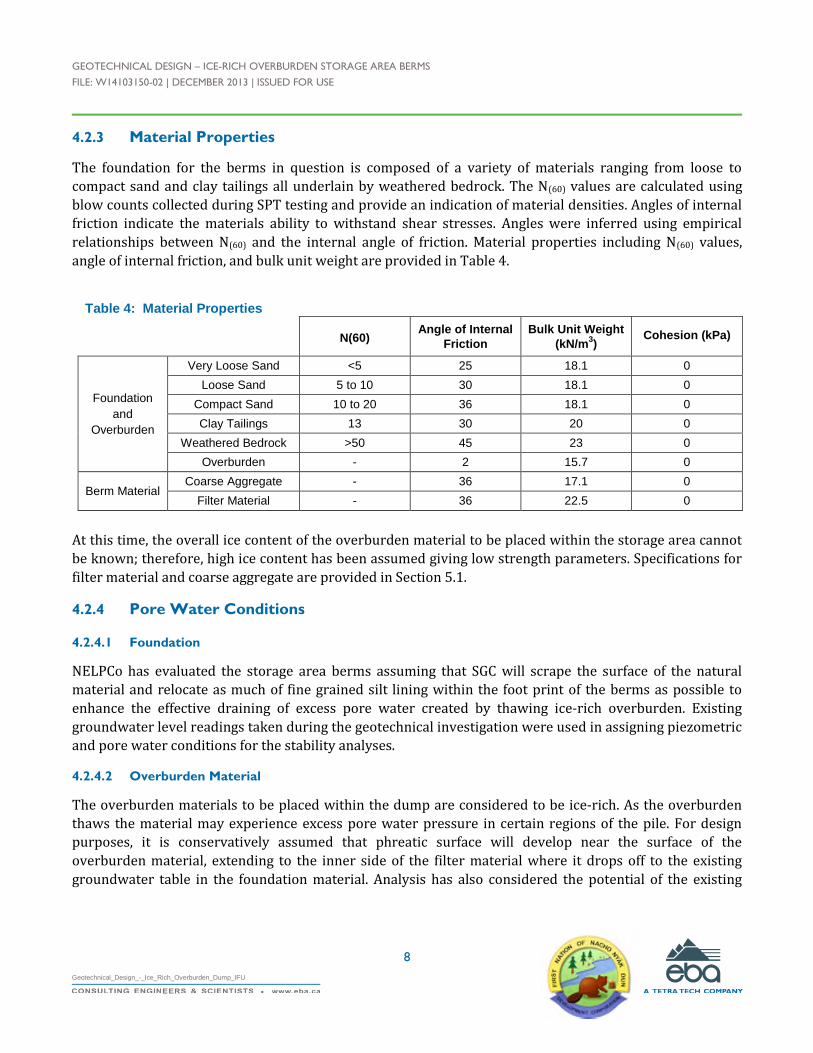
GEOTECHNICAL DESIGN – ICE-RICH OVERBURDEN STORAGE AREA BERMS
FILE: W14103150-02 | DECEMBER 2013 | ISSUED FOR USE
8
Geotechnical_Design_-_Ice_Rich_Overburden_Dump_IFU
4.2.3 Material Properties
The foundation for the berms in question is composed of a variety of materials ranging from loose to
compact sand and clay tailings all underlain by weathered bedrock. The N(60) values are calculated using
blow counts collected during SPT testing and provide an indication of material densities. Angles of internal
friction indicate the materials ability to withstand shear stresses. Angles were inferred using empirical
relationships between N(60) and the internal angle of friction. Material properties including N(60) values,
angle of internal friction, and bulk unit weight are provided in Table 4.
Table 4: Material Properties
N(60)Angle of Internal
Friction
Bulk Unit Weight
(kN/m3)
Cohesion (kPa)
Foundation
and
Overburden
Very Loose Sand <5 25 18.1 0
Loose Sand 5 to 10 30 18.1 0
Compact Sand 10 to 20 36 18.1 0
Clay Tailings 13 30 20 0
Weathered Bedrock >50 45 23 0
Overburden - 2 15.7 0
Berm MaterialCoarse Aggregate - 36 17.1 0
Filter Material - 36 22.5 0
At this time, the overall ice content of the overburden material to be placed within the storage area cannot
be known; therefore, high ice content has been assumed giving low strength parameters. Specifications for
filter material and coarse aggregate are provided in Section 5.1.
4.2.4 Pore Water Conditions
4.2.4.1 Foundation
NELPCo has evaluated the storage area berms assuming that SGC will scrape the surface of the natural
material and relocate as much of fine grained silt lining within the foot print of the berms as possible to
enhance the effective draining of excess pore water created by thawing ice-rich overburden. Existing
groundwater level readings taken during the geotechnical investigation were used in assigning piezometric
and pore water conditions for the stability analyses.
4.2.4.2 Overburden Material
The overburden materials to be placed within the dump are considered to be ice-rich. As the overburden
thaws the material may experience excess pore water pressure in certain regions of the pile. For design
purposes, it is conservatively assumed that phreatic surface will develop near the surface of the
overburden material, extending to the inner side of the filter material where it drops off to the existing
groundwater table in the foundation material. Analysis has also considered the potential of the existing
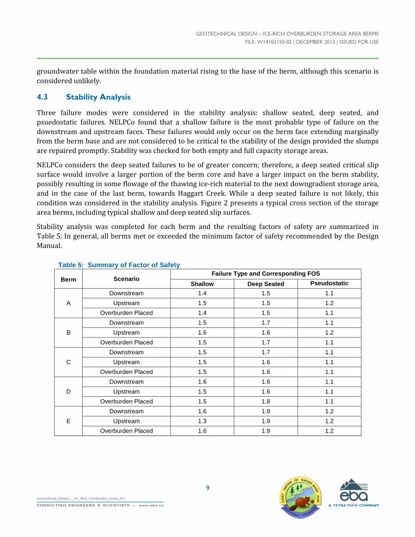
GEOTECHNICAL DESIGN – ICE-RICH OVERBURDEN STORAGE AREA BERMS
FILE: W14103150-02 | DECEMBER 2013 | ISSUED FOR USE
9
Geotechnical_Design_-_Ice_Rich_Overburden_Dump_IFU
groundwater table within the foundation material rising to the base of the berm, although this scenario is
considered unlikely.
4.3 Stability Analysis
Three failure modes were considered in the stability analysis: shallow seated, deep seated, and
psuedostatic failures. NELPCo found that a shallow failure is the most probable type of failure on the
downstream and upstream faces. These failures would only occur on the berm face extending marginally
from the berm base and are not considered to be critical to the stability of the design provided the slumps
are repaired promptly. Stability was checked for both empty and full capacity storage areas.
NELPCo considers the deep seated failures to be of greater concern; therefore, a deep seated critical slip
surface would involve a larger portion of the berm core and have a larger impact on the berm stability,
possibly resulting in some flowage of the thawing ice-rich material to the next downgradient storage area,
and in the case of the last berm, towards Haggart Creek. While a deep seated failure is not likely, this
condition was considered in the stability analysis. Figure 2 presents a typical cross section of the storage
area berms, including typical shallow and deep seated slip surfaces.
Stability analysis was completed for each berm and the resulting factors of safety are summarized in
Table 5. In general, all berms met or exceeded the minimum factor of safety recommended by the Design
Manual.
Table 5: Summary of Factor of Safety
Berm ScenarioFailure Type and Corresponding FOS
Shallow Deep Seated Pseudostatic
A
Downstream 1.4 1.5 1.1
Upstream 1.5 1.5 1.2
Overburden Placed 1.4 1.5 1.1
B
Downstream 1.5 1.7 1.1
Upstream 1.6 1.6 1.2
Overburden Placed 1.5 1.7 1.1
C
Downstream 1.5 1.7 1.1
Upstream 1.5 1.6 1.1
Overburden Placed 1.5 1.6 1.1
D
Downstream 1.6 1.6 1.1
Upstream 1.5 1.6 1.1
Overburden Placed 1.5 1.8 1.1
E
Downstream 1.6 1.9 1.2
Upstream 1.3 1.9 1.2
Overburden Placed 1.6 1.9 1.2

GEOTECHNICAL DESIGN – ICE-RICH OVERBURDEN STORAGE AREA BERMS
FILE: W14103150-02 | DECEMBER 2013 | ISSUED FOR USE
10
Geotechnical_Design_-_Ice_Rich_Overburden_Dump_IFU
4.3.1 Static Case – Empty Storage Area
This scenario presumes the possibility of a storage area berm built and the storage area left empty for an
undetermined duration of time. Each analysis resulted in factors of safety exceeding the minimum factor of
safety of 1.3. Shallow failures occurred on the upstream and downstream facing slopes with a factor of
safety ranging from 1.3 to 1.6.
4.3.2 Static Case – Full Capacity
A static analysis was completed for the storage area at full capacity. The overburden was assumed to be
thawed and fully saturated. This condition is considered unlikely to develop provided the excess pore
water is able to drain through the flow through berm.
Shallow failures on the downstream face of the berms had factors of safety ranging from 1.4 to 1.6, with the
analyzed cases exceeding the minimum of 1.3. As in Section 4.3.1, these shallow failures are not expected to
impact the stability of the berm if they are repaired promptly. A critical slip surface was analyzed that
would impact the ability of the berm to retain overburden material. Deep seated failures exceeded the
minimum recommended factor of safety, ranging from 1.5 to 1.9.
Saturation of the overburden material would be considered unlikely if the fine grained material lining the
existing berm area was removed prior to storing ice-rich material and surface water runoff is managed
appropriately. If those conditions are met, the factor of safety of the berms will to increase.
4.3.3 Pseudostatic Analysis
A pseusdostatic analysis was conducted for the full capacity case as well as for the empty storage area case.
A PGA of 0.139 g, estimated using the National Building Code of Canada, 2010 was inputted into the
stability model. The deep seated failures yielded factors of safety ranging from 1.1 to 1.2. The psuedostatic
analysis has been characterized as conservative in its approach by the Design Manual. Therefore, the
minimum FOS of 1.0 is acceptable for the purpose of this analysis.
The analysis assumed the phreatic surface has developed within the ice-rich overburden that extends into
the storage berm. This assumption resulted in a conservative factor of safety.
A seismic movement analysis was completed on berm C (the tallest berm proposed) using two methods
recommended in Appendix E of the British Columbian Guidelines for Legislated Landslide Assessments.
The results of the movement analysis indicate that the berms will not experience a slope displacement
greater than 150 mm. This movement is considered acceptable since the berms are earth structures and
are able to accommodate such deformations and still perform their intended design function.
4.3.4 Discussion
The build-up of pore water pressures within the berm will negatively impact stability. Ensuring that the
foundation area for each berm is adequately scarified to encourage exfiltration of melt water from thawing
ice-rich material is critical to the overall stability of the storage area. To ensure that water adequately
drains through the storage berm, it is also crucial to ensure that coarse grained aggregate is used for its
construction.

GEOTECHNICAL DESIGN – ICE-RICH OVERBURDEN STORAGE AREA BERMS
FILE: W14103150-02 | DECEMBER 2013 | ISSUED FOR USE
11
Geotechnical_Design_-_Ice_Rich_Overburden_Dump_IFU
Surface water runoff may be intercepted and diverted to reduce runoff into the storage areas and avoid
standing water and the creation of trafficability concerns. Methods of managing surface water and run-off
from upgradient areas are further discussed in Section 5.3.
5.0 CONSTRUCTION PLAN
5.1 Materials
Samples were taken from coarse and fine sections of the tailings material borrow source for grain size
distribution testing. Coarse aggregate was sourced from Location 1, and filter material was sourced from
Location 2 shown on Figure 1. The resulting distribution curves are included in Appendix D.
5.1.1 Coarse Aggregate Berm
NELPCo has assumed that the bulk of the berms will be constructed with 25 to 200 mm diameter material
with little to no fine grained gravel. To facilitate proper drainage and avoid the build-up of pore water
pressure in the berm, the material should contain less than 5% of 25 mm minus material. One method of
ensuring a low percentage of fine grained material is to screen the borrow source prior to placement.
Coarse aggregate may be placed in lifts up to 1.5 m thick depending on the maximum size of the rock used.
Track packing with heavy construction equipment evenly over each lift will provide sufficient compaction
of the material. It should be noted that the material placement should be done in a manner that does not
segregate or nest coarse material.
5.1.2 Filter Material
The filter material used on the upstream facing slope should meet the following grain-size specifications:
Table 6: Gradation of 75 mm Filter Material
Sieve Size (mm) % Passing by Mass
75 100
25 80-100
12.5 65-100
5 45-80
0.825 15-45
0.425 10-35
0.16 5-23
0.08 0-15
A grain size distribution analysis was completed on 75 mm minus tailings. The grain size distribution test
result confirms that the filter material meets specifications. The filter material should be placed in lifts no
thicker than 300 mm and should be nominally compacted, or track packed, to favour permeability over
compaction.

GEOTECHNICAL DESIGN – ICE-RICH OVERBURDEN STORAGE AREA BERMS
FILE: W14103150-02 | DECEMBER 2013 | ISSUED FOR USE
12
Geotechnical_Design_-_Ice_Rich_Overburden_Dump_IFU
5.2 Foundation Preparation
NELPCo recommends relocating as much the silt and clay tailings as reasonably possible along the
upstream toe of each storage area berm to allow for increased infiltration of excess pore water into the
subsurface ground water. The material is assumed to stay within the perimeter of the IROSA. Excavation
areas and volumes are detailed on Figure 2. The existing soil within the footprint of the storage area berm
should be scarified to enhance bonding between the natural soils and fill. The berm should be keyed into
the side slopes, where feasible, by at least a meter to create interlocking of the fill and side slopes.
Sections of the underlying soils have been characterized as loose granular sands. It is estimated that some
consolidation of the underlying soils will occur during the construction phase.
5.3 Surface Water Management
Management of eastern slope runoff above the storage area is important in minimizing the potential for the
collection of an excessive volume of surface water in each storage area, which could affect berm stability
and/or trafficability of the storage area. A drainage ditch was observed on the upslope side of the
abandoned access road that traversed above the eastern till cliffs and is shown on Figure 1. The existing
portion of the ditch should be cleared and re-graded to allow for positive drainage along the abandoned
access road. If required to reduce surface runoff from draining into the storage areas, the ditch could be
extended northward from the abandoned access road to increase its catchment where practical. The
Haggart Creek Road ditch was re-routed in fall 2013 after the site investigation work, and now directs
drainage away from the most northern storage area.
Surface water runoff within the storage area is also important to the performance of the IROSA. Perched
ground water lenses may develop in the overburden if surface water becomes trapped in depressions and
could result in soft surfaces and reduced trafficability. Where practical, SGC should grade the overburden
material to promote positive drainage towards the berms and side slopes of each storage area.
5.4 Quality Assurance
A construction quality assurance plan should be developed to ensure that the parameters used during the
design process are achieved. Elements to consider include:
Monitoring of fill material particle size distribution and placement;
Photographs of the construction process at each stage of construction; and
Preparation of construction record drawings signed and sealed by a professional engineer registered
in the Yukon.
Detailed specifications and quality control measures will be part of the preparation of Issued for
Construction Design drawings.

GEOTECHNICAL DESIGN – ICE-RICH OVERBURDEN STORAGE AREA BERMS
FILE: W14103150-02 | DECEMBER 2013 | ISSUED FOR USE
13
Geotechnical_Design_-_Ice_Rich_Overburden_Dump_IFU
6.0 MONITORING REQUIREMENTS
For a Class II dump, the guidelines specify visual monitoring with basic instrumentation. Visual inspections
should be completed periodically (e.g., based on specific weather conditions and IROSA activity) to check
for signs of instability including tension cracking, surficial sloughing, bulging, or seepage zones along the
downstream face of the berm.
Prior to construction, water levels in the existing piezometers/wells should be read a sufficient number of
times to establish baseline ground water table conditions. Once construction begins, instrumentation
should be monitored regularly to inform the construction process until the berm construction is completed.
A benchmark should be established and survey pins should be installed along the crests of each berm.
These pins should be surveyed twice a year, once in spring and once in fall, to monitor settlements and
lateral movements of the berms. The frequency of surveying should increase if evidence of movement or
instability is observed, or be discontinued once the downgradient storage area is filled to the berm location.
7.0 CONCEPTUAL ABANDONMENT AND RESTORATION
SGC may desire to use some of the overburden material for mine reclamation. This will be described in the
preliminary decommissioning and reclamation plan to be completed by SGC as required by the Quartz
Mining and Yukon Waters Acts. The overburden not used for reclamation of mine site facilities that remain
within the storage areas after mine closure should be graded to promote positive drainage, and re-seeded
to promote regrowth. A detailed reclamation plan is not included in NELPCo’s scope of work but can be
developed at SGC’s request.
8.0 LIMITATIONS OF REPORT
This report and its contents are intended for the sole use of SGC and their agents NND EBA Land Protection
Corp., does not accept any responsibility for the accuracy of any of the data, the analysis, or the
recommendations contained or referenced in the report when the report is used or relied upon by any
Party other than SGC, or for any Project other than the proposed development at the subject site. Any such
unauthorized use of this report is at the sole risk of the user. Use of this report is subject to the terms and
conditions stated in NELPCo’s Services Agreement. NELPCo’s General Conditions are provided in
Appendix A of this report.

GEOTECHNICAL DESIGN – ICE-RICH OVERBURDEN STORAGE AREA BERMS
FILE: W14103150-02 | DECEMBER 2013 | ISSUED FOR USE
14
Geotechnical_Design_-_Ice_Rich_Overburden_Dump_IFU
9.0 CLOSURE
We trust this report meets your present requirements. If you have any questions or comments, please
contact the undersigned.
Respectfully submitted,NND EBA Land Protection Corp.
Prepared by:
Kisa Elmer, B. Eng., EIT
Geotechnical Engineer, Arctic Group
Direct Line: 867.668.9232
Ian MacIntyre
Geotechnical Technician, Arctic Region
Direct Line: 867.668.9240
Reviewed by:
Chad Cowan, P.Eng.
Project Director – Yukon, Arctic Region
Direct Line: 867.668.9214
GEOTECHNICAL DESIGN – ICE-RICH OVERBURDEN STORAGE AREA BERMS
FILE: W14103150-02 | DECEMBER 2013 | ISSUED FOR USE
Geotechnical_Design_-_Ice_Rich_Overburden_Dump_IFU
TABLES
Table 1 Eagle Gold Property IOSA 2013 Geotechnical Investigation Summary
Table 2 Estimated Storage Capacity and Volume of Berm Material (in text)
Table 3 Minimum Factor of Safety (in text)
Table 4 Material Properties (in text)
Table 5 Summary of Factor of Safety (in text)
Table 6 Gradation of 75 mm Filter Material (in text)

VICTORIA GOLD ICE RICH OVERBURDEN DUMP GEOTECHNICAL INVESTIGATION - EAGLE GOLD PROPERTY
EBA FILE: W14103150-02 | DECEMBER 2013 | ISSUED FOR USE
Table 1: Eagle Gold Property IROSA 2013 Geotechnical Investigation Summary
Nothing Easting Elevation Date GW (m bgs)Water
Elevation
MW01 19-Sep-13 7098661 458296 746 10.7 35 10.6 735.3
Tailings (0-4.9 m), Clay [Tailings
pond](4.9 m - 7.6 m), Sand (7.6
m - 9.3 m), Silt [Till](9.3 m - 10.6
m), Bedrock (10.6 m)
Monitoring Well 0.7 0.88 7.71 9.21 22-Sep-13 6.14 739.86
BH01 19-Sep-13 7098615 458364 746 9.6 31 7.6 736.4
Tailings (0-3 m), Sand [Till](3 m -
7.6 m), Weathered Bedrock (7.6
m)
Standpipe 0.9 1 7.85 9.35 22-Sep-13 7.30 738.70
Monitoring Well 0.77 0.96 7.83 9.33 22-Sep-13 8.10 743.90
Standpipe 0.77 0.96 10.17 11.67 22-Sep-13 8.10 743.90
BH02 20-Sep-13 7098925 458410 751 16.2 53 - -Tailings (0 - 13.7 m), Sand (13.7
m - 16.2 m), Till (16.2 m)Standpipe 0.84 0.97 13.83 15.33 22-Sep-13 7.00 744.00
BH03 21-Sep-13 7099029 458299 749 11.6 38 9 740
Tailings (0-6.1 m), Silt [Till](6.1
m - 9.4 m), Weathered Bedrock
(9.4 m -11.6 m)
Standpipe 0.78 0.95 10.00 11.5 22-Sep-13 5.35 743.65
BH04 21-Sep-13 7099158 458400 740 7.9 26 7.7 732
Tailings (0 m - 1.5 m), Silt and
Sand (1.5 m - 7.7 m), Weathered
Bedrock (7.7 m - 7.9 m)
Standpipe 0.86 0.95 4.44 5.94 22-Sep-13 3.84 736.16
MW03 22-Sep-13 7099189 458293 756 6.5 21 6.1 750
Tailings [Boulders and cobbles]
(0 - 6.1 m), Weathered Till or
Bedrock (6.1 - 6.5 m)
Monitoring Well 0.76 0.9 4.75 6.2 22-Sep-13 - -
Total 74.1
Feet 243
Water Level Reading
-Tailings (0 - 9.1 m), Sand (9.1 m
- 11.6 m)
PVC stick
up (m)
Monument
stick up (m)
Top of Screen
(m bgs)
Bottom of
Well (m bgs)
Borehole
ID
Date
Completed
Completion
Depth (m)ft
Depth to
Bedrock (m)
MW02 20-Sep-13 7098938 458334 11.6 38752
Location (UTM)
Brief Soil LithologyInstrumentation
Installed
Inferred
Bedrock
Elevation
-
Table 1 Geotech Investigation Summary

GEOTECHNICAL DESIGN – ICE-RICH OVERBURDEN STORAGE AREA BERMS
FILE: W14103150-02 | DECEMBER 2013 | ISSUED FOR USE
Geotechnical_Design_-_Ice_Rich_Overburden_Dump_IFU
FIGURES
Figure 1 Site Plan Showing Proposed Storage Berm Locations
Figure 2 Typical Berm Cross-section
Figure 3 Cross-sections A – E
Figure 4 Cross-sections F – J
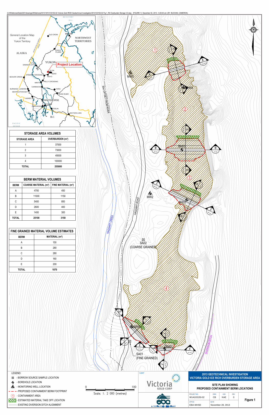
30m OFFSET FROM RIVER
HAGG
ART
CREE
K HAGG
ART
ROAD
MW01
MW2
MW3
BH01
BH02
BH04
BH03
1
2
3
4
DIVE
RSIO
N DI
TCH
SA02(COARSE GRAINED)
SA01(FINE GRAINED)
U
N
I
T
E
D
S
T
A
T
E
S
O
F
A
M
E
R
I
C
A
C
A
N
A
D
A
YUKON
NORTHWESTTERRITORIES
ALASKAEAGLE
WHITEHORSE
INUVIK
DAWSON CITY
BEAVER CREEK
MAYO
STEWART CROSSING
PELLY CROSSING
CARMACKS
FARO
ROSS RIVER
TESLIN
WATSON LAKE
DESTRUCTION BAY
BURWASH LANDING
TAGISH
ELSA
KENO
HAINES JCT
MINTO
OLD CROW
CARCROSS
PLAINS
B.C
General Location Mapof the
Yukon Territory
Project Location
Q:\Whitehorse\Data\0201drawings\Whitehorse\W141\W14103150-02 Victoria Gold IROD Geotechnical Investigation\W14103150-02 Fig.1_R0 Overburden Storage V2.dwg [FIGURE 1] December 02, 2013 - 9:28:40 am (BY: BUCHAN, CAMERON)
CLIENT
PROJECT NO. DWN CKD REV
OFFICE DATEFigure 1
November 28, 2013EBA-WHSE
0KAECBW14103150-02
SITE PLAN SHOWINGPROPOSED CONTAINMENT BERM LOCATIONS
LEGEND: - BORROW SOURCE SAMPLE LOCATION
- BOREHOLE LOCATION - MONITORING WELL LOCATION - PROPOSED CONTAINMENT BERM FOOTPRINT - CONTAINMENT AREA - ESTIMATED MATERIAL TAKE OFF LOCATION - EXISTING DIVERSION DITCH ALIGNMENT
2013 GEOTECHNICAL INVESTIGATIONVICTORIA GOLD ICE RICH OVERBURDEN STORAGE AREA
STORAGE AREA VOLUMESSTORAGE AREA OVERBURDEN (m³)
1 37000
2 73000
3 45000
4 100000
TOTAL 255000
1
BERM MATERIAL VOLUMESBERM COARSE MATERIAL (m³) FINE MATERIAL (m³)
A 4700 450
B 11000 1150
C 5400 850
D 2600 400
E 1400 300
TOTAL 25100 3150
FINE GRAINED MATERIAL VOLUME ESTIMATESBERM MATERIAL (m³)
A 150
B 280
C 280
D 160
E 200
TOTAL 1070
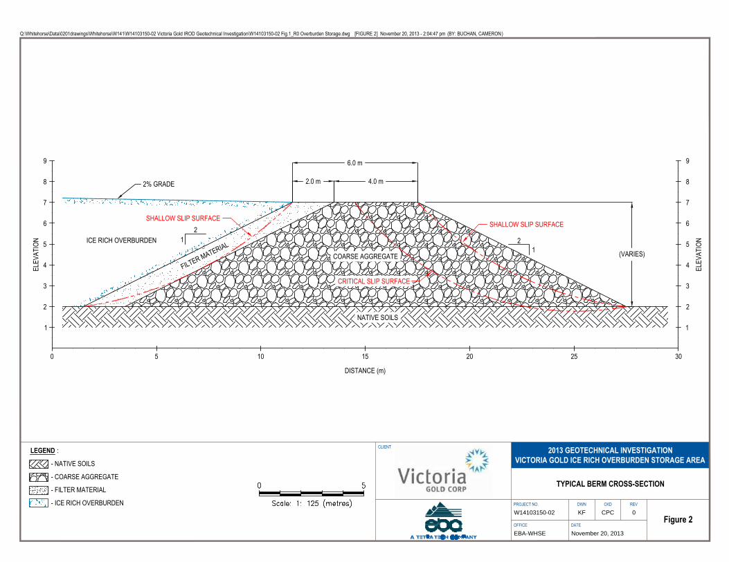
2.0 m 4.0 m
21 2
1 (VARIES)
2% GRADE
ICE RICH OVERBURDEN
FILTER MATERIALCOARSE AGGREGATE
NATIVE SOILS
6.0 m
DISTANCE (m)
ELEV
ATIO
N
0 5 10 15 20 25 30
1
2
3
4
5
6
7
8
9
ELEV
ATIO
N
1
2
3
4
5
6
7
8
9
CRITICAL SLIP SURFACE
SHALLOW SLIP SURFACESHALLOW SLIP SURFACE
Q:\Whitehorse\Data\0201drawings\Whitehorse\W141\W14103150-02 Victoria Gold IROD Geotechnical Investigation\W14103150-02 Fig.1_R0 Overburden Storage.dwg [FIGURE 2] November 20, 2013 - 2:04:47 pm (BY: BUCHAN, CAMERON)
CLIENT
PROJECT NO. DWN CKD REV
OFFICE DATEFigure 2
November 20, 2013EBA-WHSE
0CPCKFW14103150-02
TYPICAL BERM CROSS-SECTION
LEGEND :
- NATIVE SOILS
- COARSE AGGREGATE
- FILTER MATERIAL
- ICE RICH OVERBURDEN
2013 GEOTECHNICAL INVESTIGATIONVICTORIA GOLD ICE RICH OVERBURDEN STORAGE AREA
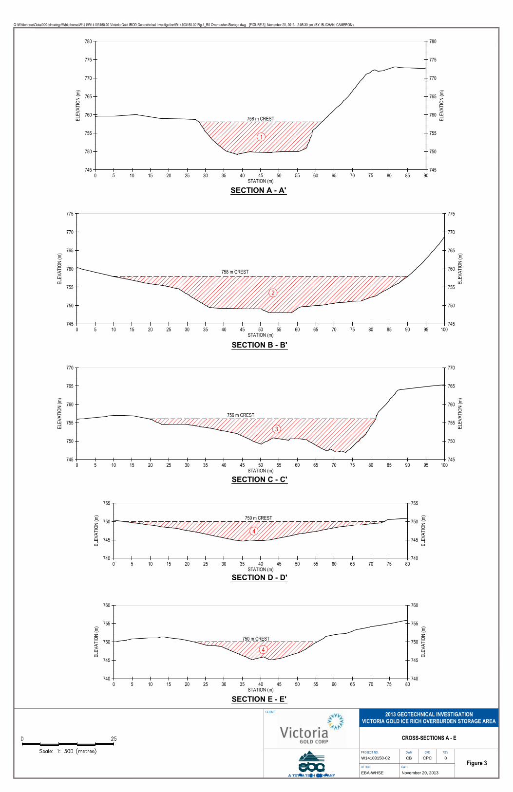
ELEV
ATIO
N (m
)
ELEV
ATIO
N (m
)
STATION (m)
745
750
755
760
765
770
775
780
745
750
755
760
765
770
775
780
0 5 10 15 20 25 30 35 40 45 50 55 60 65 70 75 80 85 90
758 m CREST
1
ELEV
ATIO
N (m
)
ELEV
ATIO
N (m
)
STATION (m)
745
750
755
760
765
770
775
745
750
755
760
765
770
775
0 5 10 15 20 25 30 35 40 45 50 55 60 65 70 75 80 85 90 95 100
758 m CREST
2
ELEV
ATIO
N (m
)
ELEV
ATIO
N (m
)
STATION (m)
745
750
755
760
765
770
745
750
755
760
765
770
0 5 10 15 20 25 30 35 40 45 50 55 60 65 70 75 80 85 90 95 100
756 m CREST
3
ELEV
ATIO
N (m
)
ELEV
ATIO
N (m
)
STATION (m)
740
745
750
755
740
745
750
755
0 5 10 15 20 25 30 35 40 45 50 55 60 65 70 75 80
750 m CREST
4
ELEV
ATIO
N (m
)
ELEV
ATIO
N (m
)
STATION (m)
740
745
750
755
760
740
745
750
755
760
0 5 10 15 20 25 30 35 40 45 50 55 60 65 70 75 80
750 m CREST
4
Q:\Whitehorse\Data\0201drawings\Whitehorse\W141\W14103150-02 Victoria Gold IROD Geotechnical Investigation\W14103150-02 Fig.1_R0 Overburden Storage.dwg [FIGURE 3] November 20, 2013 - 2:05:30 pm (BY: BUCHAN, CAMERON)
CLIENT
PROJECT NO. DWN CKD REV
OFFICE DATEFigure 3
November 20, 2013EBA-WHSE
0CPCCBW14103150-02
CROSS-SECTIONS A - E
SECTION A - A'
SECTION B - B'
SECTION C - C'
SECTION D - D'
SECTION E - E'
2013 GEOTECHNICAL INVESTIGATIONVICTORIA GOLD ICE RICH OVERBURDEN STORAGE AREA

ELEV
ATIO
N (m
)
ELEV
ATIO
N (m
)
STATION (m)
740
745
750
755
760
765
740
745
750
755
760
765
0 5 10 15 20 25 30 35 40 45 50 55 60
12
6.0
12
ELEV
ATIO
N (m
)
ELEV
ATIO
N (m
)
STATION (m)
740
745
750
755
760
765
740
745
750
755
760
765
0 5 10 15 20 25 30 35 40 45 50 55 60
12
6.0
12
ELEV
ATIO
N (m
)
ELEV
ATIO
N (m
)
STATION (m)
740
745
750
755
760
765
740
745
750
755
760
765
0 5 10 15 20 25 30 35 40 45 50
12
6.0
12
ELEV
ATIO
N (m
)
ELEV
ATIO
N (m
)
STATION (m)
735
740
745
750
755
735
740
745
750
755
0 5 10 15 20 25 30 35 40
12
6.0
12
ELEV
ATIO
N (m
)
ELEV
ATIO
N (m
)
STATION (m)
735
740
745
750
755
735
740
745
750
755
0 5 10 15 20 25 30 35 40
12
6.0
12
Q:\Whitehorse\Data\0201drawings\Whitehorse\W141\W14103150-02 Victoria Gold IROD Geotechnical Investigation\W14103150-02 Fig.1_R0 Overburden Storage.dwg [FIGURE 4] November 20, 2013 - 2:06:20 pm (BY: BUCHAN, CAMERON)
CLIENT
PROJECT NO. DWN CKD REV
OFFICE DATEFigure 4
November 20, 2013EBA-WHSE
0CPCCBW14103150-02
CROSS-SECTIONS F - J
SECTION F - F'
SECTION G - G'
SECTION H - H'
SECTION I - I' SECTION J - J'
2013 GEOTECHNICAL INVESTIGATIONVICTORIA GOLD ICE RICH OVERBURDEN STORAGE AREA
LEGEND:
- OVERBURDEN MATERIAL PLACEMENT
- FILTER MATERIAL PLACEMENT

GEOTECHNICAL DESIGN – ICE-RICH OVERBURDEN STORAGE AREA BERMS
FILE: W14103150-02 | DECEMBER 2013 | ISSUED FOR USE
Geotechnical_Design_-_Ice_Rich_Overburden_Dump_IFU
APPENDIX ANELPCO’S GENERAL CONDITIONS

General Conditions - Geotechnical.doc
GENERAL CONDITIONS
GEOTECHNICAL REPORT
This report incorporates and is subject to these “General Conditions”.
1.0 USE OF REPORT AND OWNERSHIP
This geotechnical report pertains to a specific site, a specific
development and a specific scope of work. It is not applicable to
any other sites nor should it be relied upon for types of development
other than that to which it refers. Any variation from the site or
development would necessitate a supplementary geotechnical
assessment.
This report and the recommendations contained in it are intended
for the sole use of EBA’s Client. EBA does not accept any
responsibility for the accuracy of any of the data, the analyses or
the recommendations contained or referenced in the report when
the report is used or relied upon by any party other than EBA’s
Client unless otherwise authorized in writing by EBA. Any
unauthorized use of the report is at the sole risk of the user.
This report is subject to copyright and shall not be reproduced either
wholly or in part without the prior, written permission of EBA.
Additional copies of the report, if required, may be obtained upon
request.
2.0 ALTERNATE REPORT FORMAT
Where EBA submits both electronic file and hard copy versions of
reports, drawings and other project-related documents and
deliverables (collectively termed EBA’s instruments of professional
service), only the signed and/or sealed versions shall be considered
final and legally binding. The original signed and/or sealed version
archived by EBA shall be deemed to be the original for the Project.
Both electronic file and hard copy versions of EBA’s instruments of
professional service shall not, under any circumstances, no matter
who owns or uses them, be altered by any party except EBA.
EBA’s instruments of professional service will be used only and
exactly as submitted by EBA.
Electronic files submitted by EBA have been prepared and
submitted using specific software and hardware systems. EBA
makes no representation about the compatibility of these files with
the Client’s current or future software and hardware systems.
3.0 ENVIRONMENTAL AND REGULATORY ISSUES
Unless stipulated in the report, EBA has not been retained to
investigate, address or consider and has not investigated,
addressed or considered any environmental or regulatory issues
associated with development on the subject site.
4.0 NATURE AND EXACTNESS OF SOIL ANDROCK DESCRIPTIONS
Classification and identification of soils and rocks are based upon
commonly accepted systems and methods employed in
professional geotechnical practice. This report contains
descriptions of the systems and methods used. Where deviations
from the system or method prevail, they are specifically mentioned.
Classification and identification of geological units are judgmental in
nature as to both type and condition. EBA does not warrant
conditions represented herein as exact, but infers accuracy only to
the extent that is common in practice.
Where subsurface conditions encountered during development are
different from those described in this report, qualified geotechnical
personnel should revisit the site and review recommendations in
light of the actual conditions encountered.
5.0 LOGS OF TESTHOLES
The testhole logs are a compilation of conditions and classification
of soils and rocks as obtained from field observations and
laboratory testing of selected samples. Soil and rock zones have
been interpreted. Change from one geological zone to the other,
indicated on the logs as a distinct line, can be, in fact, transitional.
The extent of transition is interpretive. Any circumstance which
requires precise definition of soil or rock zone transition elevations
may require further investigation and review.
6.0 STRATIGRAPHIC AND GEOLOGICAL INFORMATION
The stratigraphic and geological information indicated on drawings
contained in this report are inferred from logs of test holes and/or
soil/rock exposures. Stratigraphy is known only at the locations of
the test hole or exposure. Actual geology and stratigraphy between
test holes and/or exposures may vary from that shown on these
drawings. Natural variations in geological conditions are inherent
and are a function of the historic environment. EBA does not
represent the conditions illustrated as exact but recognizes that
variations will exist. Where knowledge of more precise locations of
geological units is necessary, additional investigation and review
may be necessary.

GENERAL CONDITIONSGEOTECHNICAL REPORT
2
General Conditions - Geotechnical.doc
7.0 PROTECTION OF EXPOSED GROUND
Excavation and construction operations expose geological materials
to climatic elements (freeze/thaw, wet/dry) and/or mechanical
disturbance which can cause severe deterioration. Unless
otherwise specifically indicated in this report, the walls and floors of
excavations must be protected from the elements, particularly
moisture, desiccation, frost action and construction traffic.
8.0 SUPPORT OF ADJACENT GROUND ANDSTRUCTURES
Unless otherwise specifically advised, support of ground and
structures adjacent to the anticipated construction and preservation
of adjacent ground and structures from the adverse impact of
construction activity is required.
9.0 INFLUENCE OF CONSTRUCTION ACTIVITY
There is a direct correlation between construction activity and
structural performance of adjacent buildings and other installations.
The influence of all anticipated construction activities should be
considered by the contractor, owner, architect and prime engineer
in consultation with a geotechnical engineer when the final design
and construction techniques are known.
10.0 OBSERVATIONS DURING CONSTRUCTION
Because of the nature of geological deposits, the judgmental nature
of geotechnical engineering, as well as the potential of adverse
circumstances arising from construction activity, observations
during site preparation, excavation and construction should be
carried out by a geotechnical engineer. These observations may
then serve as the basis for confirmation and/or alteration of
geotechnical recommendations or design guidelines presented
herein.
11.0 DRAINAGE SYSTEMS
Where temporary or permanent drainage systems are installed
within or around a structure, the systems which will be installed
must protect the structure from loss of ground due to internal
erosion and must be designed so as to assure continued
performance of the drains. Specific design detail of such systems
should be developed or reviewed by the geotechnical engineer.
Unless otherwise specified, it is a condition of this report that
effective temporary and permanent drainage systems are required
and that they must be considered in relation to project purpose and
function.
12.0 BEARING CAPACITY
Design bearing capacities, loads and allowable stresses quoted in
this report relate to a specific soil or rock type and condition.
Construction activity and environmental circumstances can
materially change the condition of soil or rock. The elevation at
which a soil or rock type occurs is variable. It is a requirement of
this report that structural elements be founded in and/or upon
geological materials of the type and in the condition assumed.
Sufficient observations should be made by qualified geotechnical
personnel during construction to assure that the soil and/or rock
conditions assumed in this report in fact exist at the site.
13.0 SAMPLES
EBA will retain all soil and rock samples for 30 days after this report
is issued. Further storage or transfer of samples can be made at
the Client’s expense upon written request, otherwise samples will
be discarded.
14.0 INFORMATION PROVIDED TO EBA BY OTHERS
During the performance of the work and the preparation of the
report, EBA may rely on information provided by persons other than
the Client. While EBA endeavours to verify the accuracy of such
information when instructed to do so by the Client, EBA accepts no
responsibility for the accuracy or the reliability of such information
which may affect the report.

GEOTECHNICAL DESIGN – ICE-RICH OVERBURDEN STORAGE AREA BERMS
FILE: W14103150-02 | DECEMBER 2013 | ISSUED FOR USE
Geotechnical_Design_-_Ice_Rich_Overburden_Dump_IFU
APPENDIX BBOREHOLE LOGS AND TEST RESULTS

Modified Unified Soil Classification_Arctic_Nov 2011.cdr
50%
or
more
of co
ars
e fra
ctio
nre
tain
ed o
n N
o. 4 s
ieve
Well-graded gravels and gravel-sand mixtures, little or no fines
TYPICAL DESCRIPTION
Poorly-graded gravels and gravel-sand mixtures, little or no fines
Silty gravels, gravel-sand-siltmixtures
Clayey gravels, gravel-sand-claymixtures
Well-graded sands and gravellysands, little or no fines
Poorly-graded sands and gravellysands, little or no fines
Silty sands, sand-silt mixtures
Clayey sands, sand-clay mixtures
Inorganic silts, very fine sands, rockflour, silty or clayey fine sands ofslight plasticity
Inorganic silts, micaceous ordiatomaceous fine sands or silts,elastic silts
Inorganic clays of low plasticity,gravelly clays, sandy clays, siltyclays, lean clays
Inorganic clay of mediumplasticity, silty clays
Inorganic clay of high plasticity,fat clays
Organic silts and organic siltyclays of low plasticity
Organic clays of medium to highplasticity
Peat, muck and other highly organicsoils
LABORATORY CLASSIFICATION CRITERIA
C = D / DU 60 10Greater than 4
Between 1 and 3C = C
2(D )30
D x D10 60
Atterberg limits plot below ‘A’ line orplasticity index less than 4
Atterberg limits plot above ‘A’ line andplasticity index greater than 7
D x D10 60
C = D / DU 60 10Greater than 6
Between 1 and 3C = C
2(D )30
Atterberg limits plottingin hatched area areborderline classificationsrequiring use of dualsymbols
Atterberg limits plot above ‘A’ line andplasticity index less than 4
Atterberg limits plot above ‘A’ line andplasticity index greater than 7
Atterberg limits plottingin hatched area areborderline classificationsrequiring use of dualsymbols
Cla
ssif
icati
on
on
basis
of
perc
en
tag
e o
f fi
nes
Less
than 5
% p
ass
75 µ
m s
ieve
More
than 1
2%
pass
75 µ
m s
ieve
5%
to 1
2%
pass
75 µ
m s
ieve
GW
, G
P, S
W, S
PG
M, G
C, S
M, S
CB
ord
erlin
e c
lass
ifica
tion
requirin
g u
se o
f dual s
ymbols
* Based on the material passing the 75 mm sieve
ASTM Designation D 2487, for identification procedure see D 2488 USC as modifiedby PFRA
60
50
40
30
20
1074
00 10 20 30 40 50 60 70 80 90 100
LIQUID LIMIT
PL
AS
TIC
ITY
IN
DE
X
ML or OL
MH or OH
ClCL
CL-ML
CH
‘A’ line
PLASTICITY CHART
For classification of fine-grainedsoils and fine fraction of coarse-grained soils
Equation of ‘A’ line: Pl = 0.73(LL-20)
Not meeting both criteria for GW
Not meeting both criteria for SW
MAJOR DIVISION
CO
AR
SE
- G
RA
INE
D S
OIL
S
More
than 5
0%
reta
ined o
n N
o. 75 µ
m s
ieve
*
GR
AV
EL
SS
AN
DS
More
than 50%
of co
ars
efr
act
ion p
ass
es
No. 4 s
ieve
SA
ND
SW
ITH
FIN
ES
CLE
AN
SA
ND
SG
RA
VE
LS
WIT
HF
INE
SC
LE
AN
GR
AV
ELS
HIGHLY ORGANIC SOILS
FIN
E-G
RA
INE
D S
OIL
S (
by b
eh
avio
r)
50%
or
more
pass
es
75 µ
m s
ieve
*
Ab
ove
“A
” lin
e o
np
last
icity
ch
art
ne
glig
ible
org
an
ic c
on
ten
t
Liq
uid
lim
it
>5
0
30
-50
<
30
CL
AY
S
Liq
uid
lim
it
>5
0
<5
0
OR
GA
NIC
SIL
TS
AN
D C
LA
YS
Liq
uid
lim
it
>5
0
<5
0
SIL
TS
GROUPSYMBOL
GW
GP
GM
GC
SW
SP
SM
SC
PT
ML
MH
CL
Cl
CH
OL
OH
MODIFIED UNIFIED SOIL CLASSIFICATION
VISIBLE ICE LESS THAN 50% BY VOLUME
VISIBLE ICE GREATER THAN 50% BY VOLUME
ICE NOT VISIBLE
Dual symbols are used to indicate borderline or mixedice classifications.
Visual estimates of ice contents indicated on borehole logs ± 5%
This system of ground ice description has been modified fromNRC Technical Memo 79, Guide to the Field Description ofPermafrost for Engineering Purposes.
1.
2.
3.
NOTES:
LEGEND: Soil Ice
GROUND ICE DESCRIPTION
SUBGROUP DESCRIPTIONSYMBOLGROUP
SYMBOL
Poorly-bonded or friable
No excess ice, well-bonded
Excess ice, well-bonded
Nf
Nbn
Nbe
N
Individual ice crystals or inclusions
SUBGROUP DESCRIPTIONSYMBOLGROUP
SYMBOL
Ice coatings on particles
Random or irregularly orientedice formations
Stratified or distinctly orientedice formations
Vx
Vc
Vr
Vs
V
Ice with soil inclusions
Ice without soil inclusions(greater than 25 mm thick
ICE +Soil Type
ICE
ICE

56/250mm
9
5
41
146
SAND AND GRAVEL (TAILINGS) - trace silt, angular, wellgraded, moist, very dense, brown
SILT (TAILINGS) - non plastic, grey
SAND - gravelly, some silt, subangular, well graded, weathered,moist, very dense, brown
- potential cobbles or boulders
- silty, trace gravel, wet, loose, dark grey
METAMORPHOSED QUARTZ (BEDROCK) - weathered
END OF BOREHOLE (Refusal) (9.60 metres)One inch slotted PVC standpipe installed to 9.60 metres
SP1
SP2
SP3
SP4
SP5
SHELBY TUBEA-CASING CORE
SA
MP
LEN
UM
BE
R
SA
MP
LET
YP
E
NO RECOVERY SPT
Dep
th(m
)
SAND
Ele
vatio
n(m
)
VICTORIA GOLD CORPORATION
DRILL: HOLLOW STEM AUGER
7098615N; 458364E; Zone 8
COMPLETION DEPTH: 9.6mCOMPLETE: 9/19/2013Page 1 of 1
0
SLOUGH DRILL CUTTINGSGROUTPEA GRAVELBENTONITE
LOGGED BY: KAEREVIEWED BY: CCDRAWING NO:
IROD GEOTECHNICAL INVESTIGATION
EAGLE GOLD PROPERTY
WHITEHORSE, YUKON TERRITORY
15
SAMPLE TYPE
BACKFILL TYPE
WHITEHORSE W14103150-02.GPJ EBA.GDT 13/11/19
1
2
3
4
5
6
7
8
9
10
11
12
13
14
746.0
745.0
744.0
743.0
742.0
741.0
740.0
739.0
738.0
737.0
736.0
735.0
734.0
733.0
732.0
731.0
SP
T(N
)
SOILDESCRIPTION
DISTURBED
PROJECT NO. - BOREHOLE NO.
W14103150-02-BH01
ELEVATION: 746 m
40 60 80
LIQUID
20
20
20 40 60
SILT (%)
GRAVEL (%)20 40 60 80
80
20 40 60 80
20
60
40 60 80
SAND (%)
CLAY (%)
PLASTIC M.C.
80SPT (N)40
GROUND ICEDESCRIPTION
ANDCOMMENTS
146
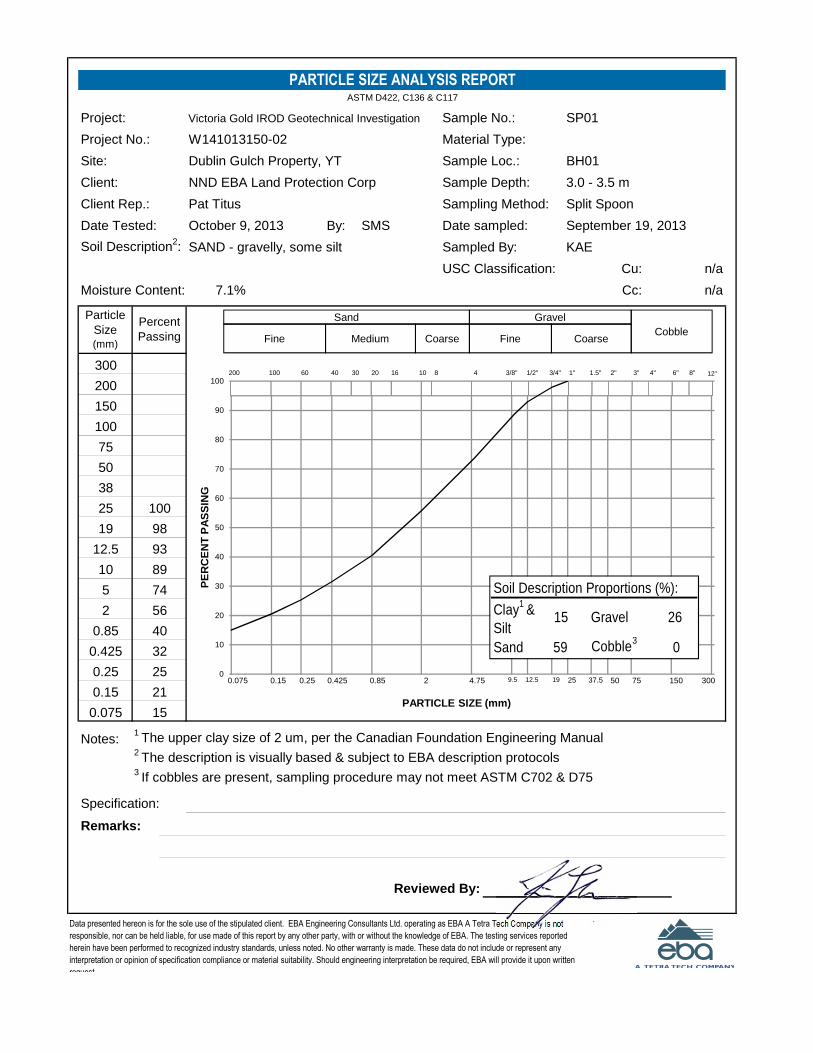
Project: Sample No.:
Project No.: Material Type:
Site: Sample Loc.:
Client: Sample Depth:
Client Rep.: Sampling Method:
Date Tested: By: Date sampled:
Soil Description2: Sampled By:
USC Classification: Cu:
Moisture Content: Cc:
Notes:1The upper clay size of 2 um, per the Canadian Foundation Engineering Manual
2The description is visually based & subject to EBA description protocols
3If cobbles are present, sampling procedure may not meet ASTM C702 & D75
Specification:
Remarks:
Reviewed By:
Data presented hereon is for the sole use of the stipulated client. EBA Engineering Consultants Ltd. operating as EBA A Tetra Tech Company is not
responsible, nor can be held liable, for use made of this report by any other party, with or without the knowledge of EBA. The testing services reported
herein have been performed to recognized industry standards, unless noted. No other warranty is made. These data do not include or represent any
interpretation or opinion of specification compliance or material suitability. Should engineering interpretation be required, EBA will provide it upon written
request.
n/a
32
25
21
15
89
74
56
40
W141013150-02
Dublin Gulch Property, YT
NND EBA Land Protection Corp
Pat Titus
100
98
93
0.85
19
12.5
10
5
0.425
0.25
0.15
0.075
Percent
Passing
25
2
200
150
100
75
50
38
PARTICLE SIZE ANALYSIS REPORTASTM D422, C136 & C117
Victoria Gold IROD Geotechnical Investigation SP01
Particle
Size(mm)
300
BH01
3.0 - 3.5 m
Split Spoon
October 9, 2013 SMS September 19, 2013
7.1% n/a
SAND - gravelly, some silt KAE
3"2"1.5"1"3/4"1/2"3/8"48101620304060100200 6" 8"4"
150755037.5251912.59.54.7520.850.4250.250.150.075
12"
3000
10
20
30
40
50
60
70
80
90
100
PE
RC
EN
TP
AS
SIN
G
PARTICLE SIZE (mm)
GravelSand
CoarseFineCoarseMediumFineCobble
Soil Description Proportions (%):
Clay1
&
Silt15 Gravel 26
Sand 59 Cobble3
0
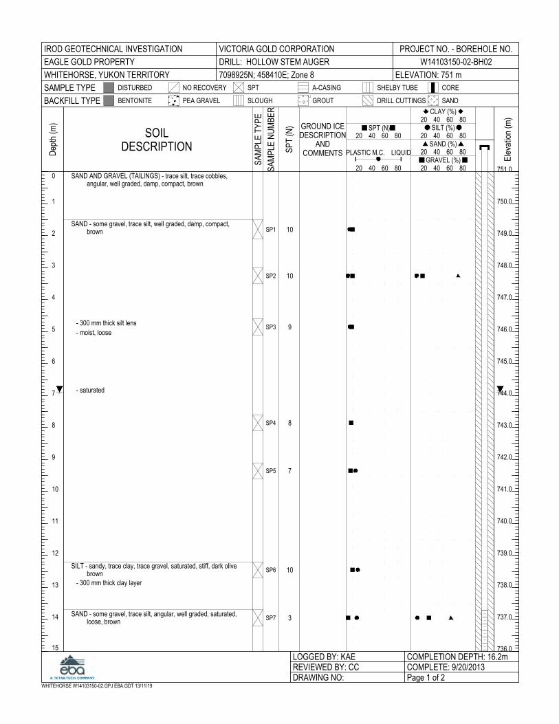
10
10
9
8
7
10
3
SAND AND GRAVEL (TAILINGS) - trace silt, trace cobbles,angular, well graded, damp, compact, brown
SAND - some gravel, trace silt, well graded, damp, compact,brown
- 300 mm thick silt lens
- moist, loose
- saturated
SILT - sandy, trace clay, trace gravel, saturated, stiff, dark olivebrown
- 300 mm thick clay layer
SAND - some gravel, trace silt, angular, well graded, saturated,loose, brown
SP1
SP2
SP3
SP4
SP5
SP6
SP7
SHELBY TUBEA-CASING CORE
SA
MP
LEN
UM
BE
R
SA
MP
LET
YP
E
NO RECOVERY SPT
Dep
th(m
)
SAND
Ele
vatio
n(m
)
VICTORIA GOLD CORPORATION
DRILL: HOLLOW STEM AUGER
7098925N; 458410E; Zone 8
COMPLETION DEPTH: 16.2mCOMPLETE: 9/20/2013Page 1 of 2
0
SLOUGH DRILL CUTTINGSGROUTPEA GRAVELBENTONITE
LOGGED BY: KAEREVIEWED BY: CCDRAWING NO:
IROD GEOTECHNICAL INVESTIGATION
EAGLE GOLD PROPERTY
WHITEHORSE, YUKON TERRITORY
15
SAMPLE TYPE
BACKFILL TYPE
WHITEHORSE W14103150-02.GPJ EBA.GDT 13/11/19
1
2
3
4
5
6
7
8
9
10
11
12
13
14
751.0
750.0
749.0
748.0
747.0
746.0
745.0
744.0
743.0
742.0
741.0
740.0
739.0
738.0
737.0
736.0
SP
T(N
)
SOILDESCRIPTION
DISTURBED
PROJECT NO. - BOREHOLE NO.
W14103150-02-BH02
ELEVATION: 751 m
40 60 80
LIQUID
20
20
20 40 60
SILT (%)
GRAVEL (%)20 40 60 80
80
20 40 60 80
20
60
40 60 80
SAND (%)
CLAY (%)
PLASTIC M.C.
80SPT (N)40
GROUND ICEDESCRIPTION
ANDCOMMENTS

8
END OF BOREHOLE (Refusal) (16.20 metres)One inch slotted PVC standpipe installed to 15.24 metresNote: Stopped due to auger refusal on till.
SP8
G1
SHELBY TUBEA-CASING CORE
SA
MP
LEN
UM
BE
R
SA
MP
LET
YP
E
NO RECOVERY SPT
Dep
th(m
)
SAND
Ele
vatio
n(m
)
VICTORIA GOLD CORPORATION
DRILL: HOLLOW STEM AUGER
7098925N; 458410E; Zone 8
COMPLETION DEPTH: 16.2mCOMPLETE: 9/20/2013Page 2 of 2
15
SLOUGH DRILL CUTTINGSGROUTPEA GRAVELBENTONITE
LOGGED BY: KAEREVIEWED BY: CCDRAWING NO:
IROD GEOTECHNICAL INVESTIGATION
EAGLE GOLD PROPERTY
WHITEHORSE, YUKON TERRITORY
30
SAMPLE TYPE
BACKFILL TYPE
WHITEHORSE W14103150-02.GPJ EBA.GDT 13/11/19
16
17
18
19
20
21
22
23
24
25
26
27
28
29
736.0
735.0
734.0
733.0
732.0
731.0
730.0
729.0
728.0
727.0
726.0
725.0
724.0
723.0
722.0
721.0
SP
T(N
)
SOILDESCRIPTION
DISTURBED
PROJECT NO. - BOREHOLE NO.
W14103150-02-BH02
ELEVATION: 751 m
40 60 80
LIQUID
20
20
20 40 60
SILT (%)
GRAVEL (%)20 40 60 80
80
20 40 60 80
20
60
40 60 80
SAND (%)
CLAY (%)
PLASTIC M.C.
80SPT (N)40
GROUND ICEDESCRIPTION
ANDCOMMENTS S
tand
pipe

Project: Sample No.:
Project No.: Material Type:
Site: Sample Loc.:
Client: Sample Depth:
Client Rep.: Sampling Method:
Date Tested: By: Date sampled:
Soil Description2: Sampled By:
USC Classification: Cu:
Moisture Content: Cc:
Notes:1The upper clay size of 2 um, per the Canadian Foundation Engineering Manual
2The description is visually based & subject to EBA description protocols
3If cobbles are present, sampling procedure may not meet ASTM C702 & D75
Specification:
Remarks:
Reviewed By:
October 9, 2013 SMS September 20, 2013
3.0% 1.8
SAND - some gravel, trace silt KAE
PARTICLE SIZE ANALYSIS REPORTASTM D422, C136 & C117
Victoria Gold IROD Geotechnical Investigation SP02
Particle
Size(mm)
300
BH02
3.0 - 3.5 m
Split Spoon
200
150
100
75
50
38
0.25
0.15
0.075
Percent
Passing
25
2
0.85
19
12.5
10
5
0.425
100
99
95
9
93
82
63
39
W141013150-02
Dublin Gulch Property, YT
NND EBA Land Protection Corp
Pat Titus
Data presented hereon is for the sole use of the stipulated client. EBA Engineering Consultants Ltd. operating as EBA A Tetra Tech Company is not
responsible, nor can be held liable, for use made of this report by any other party, with or without the knowledge of EBA. The testing services reported
herein have been performed to recognized industry standards, unless noted. No other warranty is made. These data do not include or represent any
interpretation or opinion of specification compliance or material suitability. Should engineering interpretation be required, EBA will provide it upon written
request.
16.6
23
15
12
3"2"1.5"1"3/4"1/2"3/8"48101620304060100200 6" 8"4"
150755037.5251912.59.54.7520.850.4250.250.150.075
12"
3000
10
20
30
40
50
60
70
80
90
100
PE
RC
EN
TP
AS
SIN
G
PARTICLE SIZE (mm)
GravelSand
CoarseFineCoarseMediumFineCobble
Soil Description Proportions (%):
Clay1
&
Silt9 Gravel 18
Sand 73 Cobble3
0
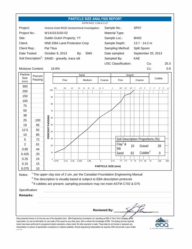
Project: Sample No.:
Project No.: Material Type:
Site: Sample Loc.:
Client: Sample Depth:
Client Rep.: Sampling Method:
Date Tested: By: Date sampled:
Soil Description2: Sampled By:
USC Classification: Cu:
Moisture Content: Cc:
Notes:1The upper clay size of 2 um, per the Canadian Foundation Engineering Manual
2The description is visually based & subject to EBA description protocols
3If cobbles are present, sampling procedure may not meet ASTM C702 & D75
Specification:
Remarks:
Reviewed By:
October 9, 2013 SMS September 20, 2013
16.6% 0.9
SAND - gravelly, trace silt KAE
PARTICLE SIZE ANALYSIS REPORTASTM D422, C136 & C117
Victoria Gold IROD Geotechnical Investigation SP07
Particle
Size(mm)
300
BH02
13.7 - 14.2 m
Split Spoon
200
150
100
75
50
38
0.25
0.15
0.075
Percent
Passing
25
2
0.85
19
12.5
10
5
0.425
100
95
92
10
85
72
61
44
W141013150-02
Dublin Gulch Property, YT
NND EBA Land Protection Corp
Pat Titus
Data presented hereon is for the sole use of the stipulated client. EBA Engineering Consultants Ltd. operating as EBA A Tetra Tech Company is not
responsible, nor can be held liable, for use made of this report by any other party, with or without the knowledge of EBA. The testing services reported
herein have been performed to recognized industry standards, unless noted. No other warranty is made. These data do not include or represent any
interpretation or opinion of specification compliance or material suitability. Should engineering interpretation be required, EBA will provide it upon written
request.
25.3
33
24
15
3"2"1.5"1"3/4"1/2"3/8"48101620304060100200 6" 8"4"
150755037.5251912.59.54.7520.850.4250.250.150.075
12"
3000
10
20
30
40
50
60
70
80
90
100
PE
RC
EN
TP
AS
SIN
G
PARTICLE SIZE (mm)
GravelSand
CoarseFineCoarseMediumFineCobble
Soil Description Proportions (%):
Clay1
&
Silt10 Gravel 28
Sand 62 Cobble3
0

8
8
7
10
72/275mm
SAND (TAILINGS) - gravelly, some cobbles andboulders, damp, dense (est.), brown
- cobbles
- silty, trace clay, well graded, saturated, loose
SILT (TILL) - sandy, trace gravel, trace clay,saturated, firm, non to low plastic, dark brown
- trace sand, moist, compact, non plastic
BEDROCK - weathered
END OF BOREHOLE (Refusal) (11.60 metres)One inch slotted PVC standpipe installed to 11.58
metres
SP1
SP2
SP3
SP4
SP5
CL-ML
SHELBY TUBEA-CASING CORE
SA
MP
LEN
UM
BE
R
SA
MP
LET
YP
E
NO RECOVERY SPT
Dep
th(m
)
SAND
Ele
vatio
n(m
)
VICTORIA GOLD CORPORATION
DRILL: HOLLOW STEM AUGER
7099029N; 458299E; Zone 8
COMPLETION DEPTH: 11.6mCOMPLETE: 9/21/2013Page 1 of 1
0
SLOUGH DRILL CUTTINGSGROUTPEA GRAVELBENTONITE
LOGGED BY: KAEREVIEWED BY: CCDRAWING NO:
IROD GEOTECHNICAL INVESTIGATION
EAGLE GOLD PROPERTY
WHITEHORSE, YUKON TERRITORY
15
SAMPLE TYPE
BACKFILL TYPE
WHITEHORSE W14103150-02.GPJ EBA.GDT 13/11/19
1
2
3
4
5
6
7
8
9
10
11
12
13
14
749.0
748.0
747.0
746.0
745.0
744.0
743.0
742.0
741.0
740.0
739.0
738.0
737.0
736.0
735.0
734.0
SP
T(N
)
SOILDESCRIPTION
DISTURBED
PROJECT NO. - BOREHOLE NO.
W14103150-02-BH03
ELEVATION: 749 m
40 60 80
LIQUID
20
20
20 40 60
SILT (%)
GRAVEL (%)20 40 60 80
80
20 40 60 80
20
60
40 60 80
SAND (%)
CLAY (%)
PLASTIC M.C.
80SPT (N)40
GROUND ICEDESCRIPTION
ANDCOMMENTS
SO
ILS
YM
BO
L

Project: Sample No.:
Project No.: Material Type:
Site: Sample Loc.:
Client: Sample Depth:
Client Rep.: Sampling Method:
Date Tested: By: Date sampled:
Soil Description2: Sampled By:
USC Classification: Cu:
Moisture Content: Cc:
Notes:1The upper clay size of 2 um, per the Canadian Foundation Engineering Manual
2The description is visually based & subject to EBA description protocols
Specification:
Remarks:
Reviewed By:
Data presented hereon is for the sole use of the stipulated client. EBA Engineering Consultants Ltd. operating as EBA A Tetra Tech Company is not
responsible, nor can be held liable, for use made of this report by any other party, with or without the knowledge of EBA. The testing services reported herein
have been performed to recognized industry standards, unless noted. No other warranty is made. These data do not include or represent any interpretation
or opinion of specification compliance or material suitability. Should engineering interpretation be required, EBA will provide it upon written request.
3.0 - 3.3 m
Split Spoon
KAE
October 4, 2013
SAND - silty, gravelly, trace clay
Victoria Gold IROD Geotechnical Investigation
W141013150-02
Dublin Gulch Property, YT
NND EBA Land Protection Corp
SMS
Pat Titus
SP01
BH03
12.5%
Particle
Size(mm)
75
50
38
PARTICLE SIZE ANALYSIS REPORTASTM D422, C136 & C117
September 21, 2013
345.9
0.3
5
2
0.85
0.425
25
19
12.5
10
0.0124
0.0089
0.0063
0.25
0.15
0.075
0.0324
0.0032
0.0013
Percent
Passing
100
95
89
0.0211
51
47
43
38
84
75
68
58
16.1
10.1
7.4
30.9
25.5
21.5
18.2
3"2"1.5"1"3/4"1/2"3/8"48101620304060100200
0.002 0.005 0.01
400
755037.5251912.59.54.7520.850.4250.250.150.0750.0370.0005 0.0010
10
20
30
40
50
60
70
80
90
100
PE
RC
EN
TP
AS
SIN
G
PARTICLE SIZE (mm)
Clay Silt
GravelSand
CoarseFineCoarsMediumFine
Soil Description Proportions (%):
Clay1
8 Sand 37
Silt 30 Gravel 25

ATTERBERG LIMITS TEST REPORTASTM D4318
Project:
Project No:
Client: Sampled By: Tested By:
Attention: Date Sampled:
Email: Date Tested:
Liquid Limit (W1) : Natural Moisture (%)
Plastic Limit : Soil Plasticity:
Plasticity Index (Ip) : Mod.USCS Symbol:
Remarks:
Reviewed By:
Depth:
Sample Description:
W14103150-02
Sample Number:
Borehole Number:
Victoria Gold IROD Geotechnical Investigation SP01
BH03
October 8, 2013
NND EBA Land Protection Corp
Pat Titus
SAND - silty, gravelly, trace clay
Dublin Gulch Property, YT
3.0 - 3.3 m
12.5
Low
CL-ML
21
13
8
Data presented hereon is for the sole use of the stipulated client. EBA Engineering Consultants Ltd. operating as EBA A Tetra Tech Company is not responsible,
nor can be held liable, for use made of this report by any other party, with or without the knowledge of EBA. The testing services reported herein have been
performed to recognized industry standards, unless noted. No other warranty is made. These data do not include or represent any interpretation or opinion of
specification compliance or material suitability. Should engineering interpretation be required, EBA will provide it upon written request.
KAE SMS
September 21, 2013
CL-ML
ML
CL
CI
ML or OL
CH
MH or OH
0
10
20
30
40
50
0 10 20 30 40 50 60 70
Pla
sti
cit
yIn
de
x(I
p)
Liquid Limit (Wl)
Plasticity Chart

Project: Sample No.:
Project No.: Material Type:
Site: Sample Loc.:
Client: Sample Depth:
Client Rep.: Sampling Method:
Date Tested: By: Date sampled:
Soil Description2: Sampled By:
USC Classification: Cu:
Moisture Content: Cc:
Notes:1The upper clay size of 2 um, per the Canadian Foundation Engineering Manual
2The description is visually based & subject to EBA description protocols
Specification:
Remarks:
Reviewed By:
18.3
12.5
9.2
43.3
33.3
25.0
21.6
72
69
66
62
94
90
84
77
0.0032
0.0013
Percent
Passing
100
97
95
0.0209
0.0124
0.0089
0.0064
0.25
0.15
0.075
0.0318
5
2
0.85
0.425
25
19
12.5
10
20.6%
Particle
Size(mm)
75
50
38
PARTICLE SIZE ANALYSIS REPORTASTM D422, C136 & C117
September 21, 2013
39.1
2.4
Victoria Gold IROD Geotechnical Investigation
W141013150-02
Dublin Gulch Property, YT
NND EBA Land Protection Corp
SMS
Pat Titus
SP03
BH03
6.1 - 6.6 m
Split Spoon
KAE
October 4, 2013
SILT - sandy, trace gravel, trace clay
Data presented hereon is for the sole use of the stipulated client. EBA Engineering Consultants Ltd. operating as EBA A Tetra Tech Company is not
responsible, nor can be held liable, for use made of this report by any other party, with or without the knowledge of EBA. The testing services reported herein
have been performed to recognized industry standards, unless noted. No other warranty is made. These data do not include or represent any interpretation
or opinion of specification compliance or material suitability. Should engineering interpretation be required, EBA will provide it upon written request.
3"2"1.5"1"3/4"1/2"3/8"48101620304060100200
0.002 0.005 0.01
400
755037.5251912.59.54.7520.850.4250.250.150.0750.0370.0005 0.0010
10
20
30
40
50
60
70
80
90
100
PE
RC
EN
TP
AS
SIN
G
PARTICLE SIZE (mm)
Clay Silt
GravelSand
CoarseFineCoarsMediumFine
Soil Description Proportions (%):
Clay1
10 Sand 28
Silt 52 Gravel 10

5
3
3
5
51/200mm
GRAVEL (TAILINGS) - sandy, some silt, trace cobbles, wellgraded, saturated, loose, brown
SAND - silty, some gravel, trace clay, well graded sand,saturated, loose, non plastic silt, brown
- very loose
- gravelly, loose
BEDROCK - weathered
END OF BOREHOLE (Refusal) (7.90 metres)One inch slotted PVC standpipe installed to 7.62 metres
SP1
SP2
SP3
SP4
SP5
SHELBY TUBEA-CASING CORE
SA
MP
LEN
UM
BE
R
SA
MP
LET
YP
E
NO RECOVERY SPT
Dep
th(m
)
SAND
Ele
vatio
n(m
)
VICTORIA GOLD CORPORATION
DRILL: HOLLOW STEM AUGER
7099158N; 458400E; Zone 8
COMPLETION DEPTH: 7.9mCOMPLETE: 9/21/2013Page 1 of 1
0
SLOUGH DRILL CUTTINGSGROUTPEA GRAVELBENTONITE
LOGGED BY: KAEREVIEWED BY: CCDRAWING NO:
IROD GEOTECHNICAL INVESTIGATION
EAGLE GOLD PROPERTY
WHITEHORSE, YUKON TERRITORY
15
SAMPLE TYPE
BACKFILL TYPE
WHITEHORSE W14103150-02.GPJ EBA.GDT 13/11/19
1
2
3
4
5
6
7
8
9
10
11
12
13
14
750.0
749.0
748.0
747.0
746.0
745.0
744.0
743.0
742.0
741.0
740.0
739.0
738.0
737.0
736.0
735.0
SP
T(N
)
SOILDESCRIPTION
DISTURBED
PROJECT NO. - BOREHOLE NO.
W14103150-02-BH04
ELEVATION: 750 m
40 60 80
LIQUID
20
20
20 40 60
SILT (%)
GRAVEL (%)20 40 60 80
80
20 40 60 80
20
60
40 60 80
SAND (%)
CLAY (%)
PLASTIC M.C.
80SPT (N)40
GROUND ICEDESCRIPTION
ANDCOMMENTS

Project: Sample No.:
Project No.: Material Type:
Site: Sample Loc.:
Client: Sample Depth:
Client Rep.: Sampling Method:
Date Tested: By: Date sampled:
Soil Description2: Sampled By:
USC Classification: Cu:
Moisture Content: Cc:
Notes:1The upper clay size of 2 um, per the Canadian Foundation Engineering Manual
2The description is visually based & subject to EBA description protocols
3If cobbles are present, sampling procedure may not meet ASTM C702 & D75
Specification:
Remarks:
Reviewed By:
October 9, 2013 SMS September 21, 2013
11.7% n/a
SAND - silty, some gravel KAE
PARTICLE SIZE ANALYSIS REPORTASTM D422, C136 & C117
Victoria Gold IROD Geotechnical Investigation SP01
Particle
Size(mm)
300
BH04
1.5 - 2.0 m
Split Spoon
200
150
100
75
50
38
0.25
0.15
0.075
Percent
Passing
25
2
0.85
19
12.5
10
5
0.425
100
28
97
86
73
59
W141013150-02
Dublin Gulch Property, YT
NND EBA Land Protection Corp
Pat Titus
Data presented hereon is for the sole use of the stipulated client. EBA Engineering Consultants Ltd. operating as EBA A Tetra Tech Company is not
responsible, nor can be held liable, for use made of this report by any other party, with or without the knowledge of EBA. The testing services reported
herein have been performed to recognized industry standards, unless noted. No other warranty is made. These data do not include or represent any
interpretation or opinion of specification compliance or material suitability. Should engineering interpretation be required, EBA will provide it upon written
request.
n/a
50
43
37
3"2"1.5"1"3/4"1/2"3/8"48101620304060100200 6" 8"4"
150755037.5251912.59.54.7520.850.4250.250.150.075
12"
3000
10
20
30
40
50
60
70
80
90
100
PE
RC
EN
TP
AS
SIN
G
PARTICLE SIZE (mm)
GravelSand
CoarseFineCoarseMediumFineCobble
Soil Description Proportions (%):
Clay1
&
Silt28 Gravel 14
Sand 58 Cobble3
0

Project: Sample No.:
Project No.: Material Type:
Site: Sample Loc.:
Client: Sample Depth:
Client Rep.: Sampling Method:
Date Tested: By: Date sampled:
Soil Description2: Sampled By:
USC Classification: Cu:
Moisture Content: Cc:
Notes:1The upper clay size of 2 um, per the Canadian Foundation Engineering Manual
2The description is visually based & subject to EBA description protocols
Specification:
Remarks:
Reviewed By:
13.3
8.4
6.0
26.5
20.5
16.9
15.1
45
41
37
33
83
73
61
52
0.0032
0.0013
Percent
Passing
100
97
86
0.0213
0.0125
0.0089
0.0064
0.25
0.15
0.075
0.0327
5
2
0.85
0.425
25
19
12.5
10
13.3%
Particle
Size(mm)
75
50
38
PARTICLE SIZE ANALYSIS REPORTASTM D422, C136 & C117
September 21, 2013
447.3
0.4
Victoria Gold IROD Geotechnical Investigation
W141013150-02
Dublin Gulch Property, YT
NND EBA Land Protection Corp
SMS
Pat Titus
SP04
BH04
6.1 - 6.6 m
Split Spoon
KAE
October 4, 2013
SAND - silty, gravelly, trace clay
Data presented hereon is for the sole use of the stipulated client. EBA Engineering Consultants Ltd. operating as EBA A Tetra Tech Company is not
responsible, nor can be held liable, for use made of this report by any other party, with or without the knowledge of EBA. The testing services reported herein
have been performed to recognized industry standards, unless noted. No other warranty is made. These data do not include or represent any interpretation
or opinion of specification compliance or material suitability. Should engineering interpretation be required, EBA will provide it upon written request.
3"2"1.5"1"3/4"1/2"3/8"48101620304060100200
0.002 0.005 0.01
400
755037.5251912.59.54.7520.850.4250.250.150.0750.0370.0005 0.0010
10
20
30
40
50
60
70
80
90
100
PE
RC
EN
TP
AS
SIN
G
PARTICLE SIZE (mm)
Clay Silt
GravelSand
CoarseFineCoarsMediumFine
Soil Description Proportions (%):
Clay1
7 Sand 40
Silt 26 Gravel 27

19
14
26
37
SAND AND GRAVEL (TAILINGS) - trace silt, angular, wellgraded, damp, compact, brown
- probable cobbles
- refusal on SPT
- probable cobble
- 600 mm thick boulder
CLAY (TAILINGS) - gravelly, some sand, some silt, angulargravel, stiff, low to medium plastic, dark grey
- wet
SAND - gravelly, trace silt, coarse grained, angular, saturated,compact, brown
SILT (TILL) - gravelly, trace sand, trace clay, matrix supported,some weathering, saturated, hard, low plastic, olive grey
- damp
BEDROCK - weathered
END OF BOREHOLE (Refusal) (10.70 metres)Two inch slotted PVC monitoring well installed to 9.14 metres
SP1
SP2
SP3
SP4
SP5SP5A
G1
SHELBY TUBEA-CASING CORE
SA
MP
LEN
UM
BE
R
SA
MP
LET
YP
E
NO RECOVERY SPT
Dep
th(m
)
SAND
Ele
vatio
n(m
)
VICTORIA GOLD CORPORATION
DRILL: HOLLOW STEM AUGER
7098661N; 458296E; Zone 8
COMPLETION DEPTH: 10.7mCOMPLETE: 9/19/2013Page 1 of 1
0
SLOUGH DRILL CUTTINGSGROUTPEA GRAVELBENTONITE
LOGGED BY: KAEREVIEWED BY: CCDRAWING NO:
IROD GEOTECHNICAL INVESTIGATION
EAGLE GOLD PROPERTY
WHITEHORSE, YUKON TERRITORY
15
SAMPLE TYPE
BACKFILL TYPE
WHITEHORSE W14103150-02.GPJ EBA.GDT 13/11/19
1
2
3
4
5
6
7
8
9
10
11
12
13
14
746.0
745.0
744.0
743.0
742.0
741.0
740.0
739.0
738.0
737.0
736.0
735.0
734.0
733.0
732.0
731.0
SP
T(N
)
SOILDESCRIPTION
DISTURBED
PROJECT NO. - BOREHOLE NO.
W14103150-02-MW01
ELEVATION: 746 m
40 60 80
LIQUID
20
20
20 40 60
SILT (%)
GRAVEL (%)20 40 60 80
80
20 40 60 80
20
60
40 60 80
SAND (%)
CLAY (%)
PLASTIC M.C.
80SPT (N)40
GROUND ICEDESCRIPTION
ANDCOMMENTS

Project: Sample No.:
Project No.: Material Type:
Site: Sample Loc.:
Client: Sample Depth:
Client Rep.: Sampling Method:
Date Tested: By: Date sampled:
Soil Description2: Sampled By:
USC Classification: Cu:
Moisture Content: Cc:
Notes:1The upper clay size of 2 um, per the Canadian Foundation Engineering Manual
2The description is visually based & subject to EBA description protocols
3If cobbles are present, sampling procedure may not meet ASTM C702 & D75
Specification:
Remarks:
Reviewed By:
October 9, 2013 SMS September 19, 2013
4.5% n/a
SAND - gravelly, some silt KAE
PARTICLE SIZE ANALYSIS REPORTASTM D422, C136 & C117
Victoria Gold IROD Geotechnical Investigation SP02
Particle
Size(mm)
300
MW01
3.0 - 3.5 m
Split Spoon
200
150
100
75
50
38
0.25
0.15
0.075
Percent
Passing
25
2
0.85
19
12.5
10
5
0.425
100
96
92
86
13
78
66
52
36
W141013150-02
Dublin Gulch Property, YT
NND EBA Land Protection Corp
Pat Titus
Data presented hereon is for the sole use of the stipulated client. EBA Engineering Consultants Ltd. operating as EBA A Tetra Tech Company is not
responsible, nor can be held liable, for use made of this report by any other party, with or without the knowledge of EBA. The testing services reported
herein have been performed to recognized industry standards, unless noted. No other warranty is made. These data do not include or represent any
interpretation or opinion of specification compliance or material suitability. Should engineering interpretation be required, EBA will provide it upon written
request.
n/a
26
20
17
3"2"1.5"1"3/4"1/2"3/8"48101620304060100200 6" 8"4"
150755037.5251912.59.54.7520.850.4250.250.150.075
12"
3000
10
20
30
40
50
60
70
80
90
100
PE
RC
EN
TP
AS
SIN
G
PARTICLE SIZE (mm)
GravelSand
CoarseFineCoarseMediumFineCobble
Soil Description Proportions (%):
Clay1
&
Silt13 Gravel 34
Sand 53 Cobble3
0

Project: Sample No.:
Project No.: Material Type:
Site: Sample Loc.:
Client: Sample Depth:
Client Rep.: Sampling Method:
Date Tested: By: Date sampled:
Soil Description2: Sampled By:
USC Classification: Cu:
Moisture Content: Cc:
Notes:1The upper clay size of 2 um, per the Canadian Foundation Engineering Manual
2The description is visually based & subject to EBA description protocols
3If cobbles are present, sampling procedure may not meet ASTM C702 & D75
Specification:
Remarks:
Reviewed By:
October 9, 2013 SMS September 19, 2013
14.6% 1.3
SAND - gravelly, trace silt KAE
PARTICLE SIZE ANALYSIS REPORTASTM D422, C136 & C117
Victoria Gold IROD Geotechnical Investigation SP04
Particle
Size(mm)
300
MW01
7.6 - 8.1 m
Split Spoon
200
150
100
75
50
38
0.25
0.15
0.075
Percent
Passing
25
2
0.85
19
12.5
10
5
0.425
100
99
92
7
86
75
60
39
W141013150-02
Dublin Gulch Property, YT
NND EBA Land Protection Corp
Pat Titus
Data presented hereon is for the sole use of the stipulated client. EBA Engineering Consultants Ltd. operating as EBA A Tetra Tech Company is not
responsible, nor can be held liable, for use made of this report by any other party, with or without the knowledge of EBA. The testing services reported
herein have been performed to recognized industry standards, unless noted. No other warranty is made. These data do not include or represent any
interpretation or opinion of specification compliance or material suitability. Should engineering interpretation be required, EBA will provide it upon written
request.
15.3
25
16
11
3"2"1.5"1"3/4"1/2"3/8"48101620304060100200 6" 8"4"
150755037.5251912.59.54.7520.850.4250.250.150.075
12"
3000
10
20
30
40
50
60
70
80
90
100
PE
RC
EN
TP
AS
SIN
G
PARTICLE SIZE (mm)
GravelSand
CoarseFineCoarseMediumFineCobble
Soil Description Proportions (%):
Clay1
&
Silt7 Gravel 25
Sand 68 Cobble3
0

50/100mm
11
9
11
12
50/75mm
GRAVEL AND SAND (TAILINGS) - tracecobbles and silt, angular, well graded,wet, hard, brown
- damp
- dark grey
- probable cobbles and boulders
SAND - gravelly, silty, well graded,subangular, moist, compact, nonplastic silt, brown, root inclusions
- cobble or boulder
- CLAY - trace silt, moist, stiff, mediumplastic, grey 200 mm thick
- saturated, olive brown
- trace silt
- medium and coarse grained, someoxidation
- hard
END OF BOREHOLE (Refusal) (11.90metres)
Two inch slotted PVC monitoring well 2Ainstalled to 11.89 metres
One inch slotted PVC monitoring well 2Binstalled to 9.14 metres
SP1
SP2
SP3SP3A
SP4
SP5
SP6
G1
CI
SHELBY TUBEA-CASING CORE
SA
MP
LEN
UM
BE
R
SA
MP
LET
YP
E
NO RECOVERY SPT
Dep
th(m
)
SAND
Ele
vatio
n(m
)
VICTORIA GOLD CORPORATION
DRILL: HOLLOW STEM AUGER
7098938N; 458334E; Zone 8
COMPLETION DEPTH: 11.9mCOMPLETE: 9/20/2013Page 1 of 1
0
SLOUGH DRILL CUTTINGSGROUTPEA GRAVELBENTONITE
LOGGED BY: KAEREVIEWED BY: CCDRAWING NO:
IROD GEOTECHNICAL INVESTIGATION
EAGLE GOLD PROPERTY
WHITEHORSE, YUKON TERRITORY
15
SAMPLE TYPE
BACKFILL TYPE
WHITEHORSE W14103150-02.GPJ EBA.GDT 13/11/19
1
2
3
4
5
6
7
8
9
10
11
12
13
14
752.0
751.0
750.0
749.0
748.0
747.0
746.0
745.0
744.0
743.0
742.0
741.0
740.0
739.0
738.0
737.0
SP
T(N
)
SOILDESCRIPTION
DISTURBED
PROJECT NO. - BOREHOLE NO.
W14103150-02-MW02
ELEVATION: 752 m
40 60 80
LIQUID
20
20
20 40 60
SILT (%)
GRAVEL (%)20 40 60 80
80
20 40 60 80
20
60
40 60 80
SAND (%)
CLAY (%)
PLASTIC M.C.
80SPT (N)40
GROUND ICEDESCRIPTION
ANDCOMMENTS
SO
ILS
YM
BO
L

Project: Sample No.:
Project No.: Material Type:
Site: Sample Loc.:
Client: Sample Depth:
Client Rep.: Sampling Method:
Date Tested: By: Date sampled:
Soil Description2: Sampled By:
USC Classification: Cu:
Moisture Content: Cc:
Notes:1The upper clay size of 2 um, per the Canadian Foundation Engineering Manual
2The description is visually based & subject to EBA description protocols
3If cobbles are present, sampling procedure may not meet ASTM C702 & D75
Specification:
Remarks:
Reviewed By:
October 9, 2013 SMS September 20, 2013
7.4% n/a
SAND - gravelly, silty KAE
PARTICLE SIZE ANALYSIS REPORTASTM D422, C136 & C117
Victoria Gold IROD Geotechnical Investigation SP02
Particle
Size(mm)
300
MW02
4.6 - 5.1 m
Split Spoon
200
150
100
75
50
38
0.25
0.15
0.075
Percent
Passing
25
2
0.85
19
12.5
10
5
0.425
100
95
95
84
21
79
68
56
43
W141013150-02
Dublin Gulch Property, YT
NND EBA Land Protection Corp
Pat Titus
Data presented hereon is for the sole use of the stipulated client. EBA Engineering Consultants Ltd. operating as EBA A Tetra Tech Company is not
responsible, nor can be held liable, for use made of this report by any other party, with or without the knowledge of EBA. The testing services reported
herein have been performed to recognized industry standards, unless noted. No other warranty is made. These data do not include or represent any
interpretation or opinion of specification compliance or material suitability. Should engineering interpretation be required, EBA will provide it upon written
request.
n/a
35
30
26
3"2"1.5"1"3/4"1/2"3/8"48101620304060100200 6" 8"4"
150755037.5251912.59.54.7520.850.4250.250.150.075
12"
3000
10
20
30
40
50
60
70
80
90
100
PE
RC
EN
TP
AS
SIN
G
PARTICLE SIZE (mm)
GravelSand
CoarseFineCoarseMediumFineCobble
Soil Description Proportions (%):
Clay1
&
Silt21 Gravel 32
Sand 47 Cobble3
0

ATTERBERG LIMITS TEST REPORTASTM D4318
Project:
Project No:
Client: Sampled By: Tested By:
Attention: Date Sampled:
Email: Date Tested:
Liquid Limit (W1) : Natural Moisture (%)
Plastic Limit : Soil Plasticity:
Plasticity Index (Ip) : Mod.USCS Symbol:
Remarks:
Reviewed By:
Data presented hereon is for the sole use of the stipulated client. EBA Engineering Consultants Ltd. operating as EBA A Tetra Tech Company is not responsible,
nor can be held liable, for use made of this report by any other party, with or without the knowledge of EBA. The testing services reported herein have been
performed to recognized industry standards, unless noted. No other warranty is made. These data do not include or represent any interpretation or opinion of
specification compliance or material suitability. Should engineering interpretation be required, EBA will provide it upon written request.
KAE SMS
September 20, 2013
40.6
Medium
CI
43
22
21
Depth:
Sample Description:
W14103150-02
Sample Number:
Borehole Number:
Victoria Gold IROD Geotechnical Investigation SP03a
MW02
October 8, 2013
NND EBA Land Protection Corp
Pat Titus
Dublin Gulch Property, YT
6.4 - 6.6 m
CL-ML
ML
CL
CI
ML or OL
CH
MH or OH
0
10
20
30
40
50
0 10 20 30 40 50 60 70
Pla
sti
cit
yIn
de
x(I
p)
Liquid Limit (Wl)
Plasticity Chart

87
SAND AND GRAVEL (TAILINGS) - trace to some silt, cobblesand boulders, damp, very dense, brown
- boulders
BEDROCK - weathered
END OF BOREHOLE (Refusal) (6.50 metres)Two inch slotted PVC monitoring well installed to 6.10 metres
SP1
SHELBY TUBEA-CASING CORE
SA
MP
LEN
UM
BE
R
SA
MP
LET
YP
E
NO RECOVERY SPT
Dep
th(m
)
SAND
Ele
vatio
n(m
)
VICTORIA GOLD CORPORATION
DRILL: HOLLOW STEM AUGER
7099189N; 458293E; Zone 8
COMPLETION DEPTH: 6.5mCOMPLETE: 9/22/2013Page 1 of 1
0
SLOUGH DRILL CUTTINGSGROUTPEA GRAVELBENTONITE
LOGGED BY: KAEREVIEWED BY: CCDRAWING NO:
IROD GEOTECHNICAL INVESTIGATION
EAGLE GOLD PROPERTY
WHITEHORSE, YUKON TERRITORY
15
SAMPLE TYPE
BACKFILL TYPE
WHITEHORSE W14103150-02.GPJ EBA.GDT 13/11/19
1
2
3
4
5
6
7
8
9
10
11
12
13
14
756.0
755.0
754.0
753.0
752.0
751.0
750.0
749.0
748.0
747.0
746.0
745.0
744.0
743.0
742.0
741.0
SP
T(N
)
SOILDESCRIPTION
DISTURBED
PROJECT NO. - BOREHOLE NO.
W14103150-02-MW03
ELEVATION: 756 m
40 60 80
LIQUID
20
20
20 40 60
SILT (%)
GRAVEL (%)20 40 60 80
80
20 40 60 80
20
60
40 60 80
SAND (%)
CLAY (%)
PLASTIC M.C.
80SPT (N)40
GROUND ICEDESCRIPTION
ANDCOMMENTS

Project: Sample No.:
Project No.: Material Type:
Site: Sample Loc.:
Client: Sample Depth:
Client Rep.: Sampling Method:
Date Tested: By: Date sampled:
Soil Description2: Sampled By:
USC Classification: Cu:
Moisture Content: Cc:
Notes:1The upper clay size of 2 um, per the Canadian Foundation Engineering Manual
2The description is visually based & subject to EBA description protocols
3If cobbles are present, sampling procedure may not meet ASTM C702 & D75
Specification:
Remarks:
Reviewed By:
October 9, 2013 SMS September 20, 2013
11.3% n/a
SAND - gravelly, trace silt KAE
PARTICLE SIZE ANALYSIS REPORTASTM D422, C136 & C117
Victoria Gold IROD Geotechnical Investigation SP05
Particle
Size(mm)
300
MW02
9.1 - 9.6 m
Split Spoon
200
150
100
75
50
38
0.25
0.15
0.075
Percent
Passing
25
2
0.85
19
12.5
10
5
0.425
100
97
94
10
91
77
61
41
W141013150-02
Dublin Gulch Property, YT
NND EBA Land Protection Corp
Pat Titus
Data presented hereon is for the sole use of the stipulated client. EBA Engineering Consultants Ltd. operating as EBA A Tetra Tech Company is not
responsible, nor can be held liable, for use made of this report by any other party, with or without the knowledge of EBA. The testing services reported
herein have been performed to recognized industry standards, unless noted. No other warranty is made. These data do not include or represent any
interpretation or opinion of specification compliance or material suitability. Should engineering interpretation be required, EBA will provide it upon written
request.
n/a
28
20
15
3"2"1.5"1"3/4"1/2"3/8"48101620304060100200 6" 8"4"
150755037.5251912.59.54.7520.850.4250.250.150.075
12"
3000
10
20
30
40
50
60
70
80
90
100
PE
RC
EN
TP
AS
SIN
G
PARTICLE SIZE (mm)
GravelSand
CoarseFineCoarseMediumFineCobble
Soil Description Proportions (%):
Clay1
&
Silt10 Gravel 23
Sand 67 Cobble3
0

GEOTECHNICAL DESIGN – ICE-RICH OVERBURDEN STORAGE AREA BERMS
FILE: W14103150-02 | DECEMBER 2013 | ISSUED FOR USE
Geotechnical_Design_-_Ice_Rich_Overburden_Dump_IFU
APPENDIX CHYDRAULIC CONDUCTIVITY TESTING
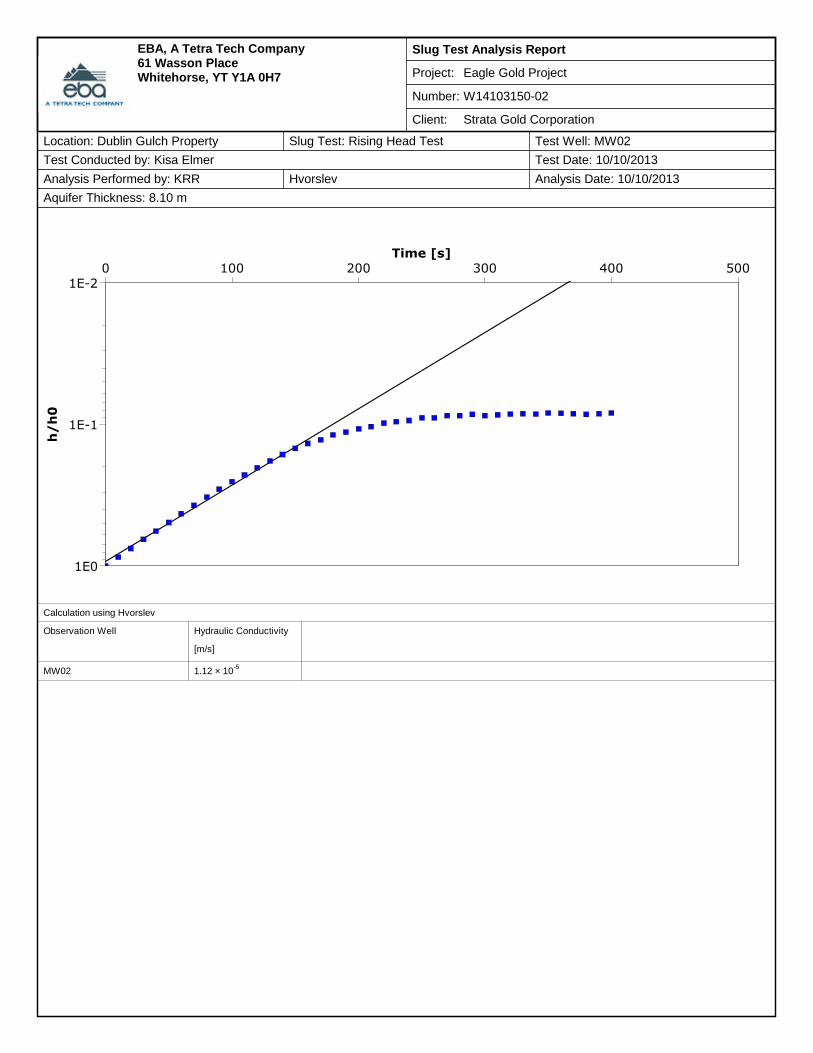
Slug Test Analysis Report
Project: Eagle Gold Project
Number: W14103150-02
Client: Strata Gold Corporation
EBA, A Tetra Tech Company61 Wasson PlaceWhitehorse, YT Y1A 0H7
Location: Dublin Gulch Property Slug Test: Rising Head Test Test Well: MW02
Test Conducted by: Kisa Elmer Test Date: 10/10/2013
Analysis Performed by: KRR Hvorslev Analysis Date: 10/10/2013
Aquifer Thickness: 8.10 m
0 100 200 300 400 500Time [s]
1E-2
1E-1
1E0
h/
h0
Calculation using Hvorslev
Observation Well Hydraulic Conductivity
[m/s]
MW02 1.12 × 10⁻⁵

Slug Test Analysis Report
Project: Eagle Gold Project
Number: W14103150-02
Client: Strata Gold Corporation
EBA, A Tetra Tech Company61 Wasson PlaceWhitehorse, YT Y1A 0H7
Location: Dublin Gulch Property Slug Test: Rising Head Test Test Well: MW02
Test Conducted by: Kisa Elmer Test Date: 10/10/2013
Analysis Performed by: KRR Bouwer & Rice Analysis Date: 10/10/2013
Aquifer Thickness: 8.10 m
0 100 200 300 400 500Time [s]
1E-2
1E-1
1E0
h/
h0
Calculation using Bouwer & Rice
Observation Well Hydraulic Conductivity
[m/s]
MW02 8.50 × 10⁻⁶
GEOTECHNICAL DESIGN – ICE-RICH OVERBURDEN STORAGE AREA BERMS
FILE: W14103150-02 | DECEMBER 2013 | ISSUED FOR USE
Geotechnical_Design_-_Ice_Rich_Overburden_Dump_IFU
APPENDIX DMATERIAL TESTING FOR BERM DESIGN

Project: Sample No.:
Project No.: Material Type:
Site: Sample Loc.:
Client: Sample Depth:
Client Rep.: Sampling Method:
Date Tested: By: Date sampled:
Soil Description2: Sampled By:
USC Classification: Cu:
Moisture Content: Cc:
Notes:1The upper clay size of 2 um, per the Canadian Foundation Engineering Manual
2The description is visually based & subject to EBA description protocols
3If cobbles are present, sampling procedure may not meet ASTM C702 & D75
Specification:
Remarks:
Reviewed By:
1.2% 0.8
GRAVEL - trace silt
1.9
Data presented hereon is for the sole use of the stipulated client. EBA Engineering Consultants Ltd. operating as EBA A Tetra Tech Company is not
responsible, nor can be held liable, for use made of this report by any other party, with or without the knowledge of EBA. The testing services reported
herein have been performed to recognized industry standards, unless noted. No other warranty is made. These data do not include or represent any
interpretation or opinion of specification compliance or material suitability. Should engineering interpretation be required, EBA will provide it upon written
request.
November 1, 2013 SP n/a
150
100
75
Client
PARTICLE SIZE ANALYSIS TEST REPORTASTM D422, C136 & C117
Victoria Gold IROD Geotechnical Investigation Coarse
Particle
Size(mm)
Percent
Passing
0.63
0.315
0.16
0.08
300
n/a
n/a
Grab
2.5
28
60
33
5
56
38
200
1.25
20
14
10
5
1
0
0
0
W141013150-02
Dublin Gulch Property, YT
NND EBA Land Protection Corp
Pat Titus
100
3
1
0
0
0
0
3"2"1.5"1"3/4"1/2"3/8"48101620304060100200 6" 8"4"
150755037.5251912.59.54.7520.850.4250.250.150.075
12"
3000
10
20
30
40
50
60
70
80
90
100
PE
RC
EN
TP
AS
SIN
G
PARTICLE SIZE (mm)
GravelSand
CoarseFineCoarseMediumFineCobble
Soil Description Proportions (%):
Clay1
&
Silt1 Gravel 100
Sand 0 Cobble3
0

Project: Sample No.:
Project No.: Material Type:
Site: Sample Loc.:
Client: Sample Depth:
Client Rep.: Sampling Method:
Date Tested: By: Date sampled:
Soil Description2: Sampled By:
USC Classification: Cu:
Moisture Content: Cc:
Notes:1The upper clay size of 2 um, per the Canadian Foundation Engineering Manual
2The description is visually based & subject to EBA description protocols
3If cobbles are present, sampling procedure may not meet ASTM C702 & D75
Specification:
Remarks:
Reviewed By:
2.3% 3.1
SAND - gravelly, trace silt
40.7
Data presented hereon is for the sole use of the stipulated client. EBA Engineering Consultants Ltd. operating as EBA A Tetra Tech Company is not
responsible, nor can be held liable, for use made of this report by any other party, with or without the knowledge of EBA. The testing services reported
herein have been performed to recognized industry standards, unless noted. No other warranty is made. These data do not include or represent any
interpretation or opinion of specification compliance or material suitability. Should engineering interpretation be required, EBA will provide it upon written
request.
November 1, 2013 SP n/a
150
100
75
Client
PARTICLE SIZE ANALYSIS TEST REPORTASTM D422, C136 & C117
Victoria Gold IROD Geotechnical Investigation Fine
Particle
Size(mm)
Percent
Passing
0.63
0.315
0.16
0.08
300
n/a
n/a
Grab
2.5
28
100
97
56
38
200
1.25
20
14
10
5
80
65
49
32
W141013150-02
Dublin Gulch Property, YT
NND EBA Land Protection Corp
Pat Titus
91
85
21
16
12
9
3"2"1.5"1"3/4"1/2"3/8"48101620304060100200 6" 8"4"
150755037.5251912.59.54.7520.850.4250.250.150.075
12"
3000
10
20
30
40
50
60
70
80
90
100
PE
RC
EN
TP
AS
SIN
G
PARTICLE SIZE (mm)
GravelSand
CoarseFineCoarseMediumFineCobble
Soil Description Proportions (%):
Clay1
&
Silt9 Gravel 35
Sand 56 Cobble3
0
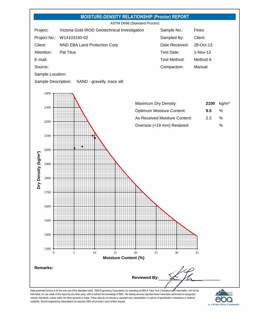
MOISTURE-DENSITY RELATIONSHIP (Proctor) REPORTASTM D698 (Standard Proctor)
kg/m³
Optimum Moisture Content: %
As Received Moisture Content: %
Oversize (+19 mm) Retained: %
Remarks:
Reviewed By:
E-mail: Method A
9.5
Test Method:
2.3
Data presented hereon is for the sole use of the stipulated client. EBA Engineering Consultants Ltd. operating as EBA A Tetra Tech Company is not responsible, nor can be
held liable, for use made of this report by any other party, with or without the knowledge of EBA. The testing services reported herein have been performed to recognized
industry standards, unless noted. No other warranty is made. These data do not include or represent any interpretation or opinion of specification compliance or material
suitability. Should engineering interpretation be required, EBA will provide it upon written request.
2100
Date Received: 28-Oct-13
Fines
Client
Sample No.:
Sampled By:
Test Date: 1-Nov-13
Victoria Gold IROD Geotechnical Investigation
W14103150-02
NND EBA Land Protection Corp
Pat Titus
Project:
Project No.:
Client:
Attention:
Manual
Sample Description:
Compaction:Source:
SAND - gravelly, trace silt
Sample Location:
Maximum Dry Density:
1300
1400
1500
1600
1700
1800
1900
2000
2100
2200
2300
2400
0 5 10 15 20 25 30 35
Dry
Den
sit
y(k
g/m
³)
Moisture Content (%)

EAGLE GOLD PROJECT - HAGGART CREEK IROSA – DESIGN UPDATE AND IFC DRAWINGS FILE: ENG.WARC03235-01 | JUNE 8, 2017 | ISSUED FOR USE
ENGWARC03235-01_Haggart Creek IROSA Design Update
APPENDIX C
ISSUED FOR CONSTRUCTION DRAWINGS

HAGGART CREEK ICE RICH OVERBURDEN STORAGE AREAEAGLE GOLD PROJECT - DUBLIN GULCH, YUKON
PREPARED FOR: PREPARED BY:
ISSUED FOR USE
SHEET LIST INDEXSHEET NUMBER SHEET TITLE
FIGURE 1 SITE PLAN SHOWING EMBANKMENT LOCATIONS
FIGURE 2 EMBANKMENT A - PLAN AND SECTIONS
FIGURE 3 EMBANKMENT B - PLAN AND SECTIONS
FIGURE 4 EMBANKMENT C - PLAN AND SECTIONS
FIGURE 5 EMBANKMENT D - PLAN AND SECTIONS
FIGURE 6 EMBANKMENT E - PLAN AND SECTIONS
FIGURE 7 DETAILS AND SPECIFICATIONS - PAGE 1
FIGURE 8 DETAILS AND SPECIFICATIONS - PAGE 2
U
N
I
T
E
D
S
T
A
T
E
S
O
F
A
M
E
R
I
C
A
C
A
N
A
D
A
YUKON
ALASKA
B.C
General Location Mapof the
Yukon Territory
TULITA
NORMAN WELLS
NORMAN WELLS COLVILLE LAKE
TSIIGEHTCHIC
INUVIK
FORT LIARD
AKLAVIK
FORT McPHERSON
TUKTOYAKTUK
KENOELSA
MAYOSTEWART CROSSING
PELLY CROSSING
CARMACKS
HAINESJUNCTION
CARCROSS
SWIFTRIVER
TESLIN
ATLIN WATSON LAKE
CANTUNG
ROSS RIVER
FARO
TAGISH
WHITEHORSE
D. BAYBURWASHLANDING
BEAVERCREEK
DAWSONCITY
EAGLEPLAINS
OLD CROW
NAHANNIBUTTE
Project Location
STRATAGOLD CORPORATION

Lynx Creek
EAGLEGOLD CAMP
H
a
g
g
a
r
t
C
r
e
e
k
R
o
a
d
HAGG
ERT
CRE
EK R
OAD
HAGG
ART
CREE
K
HAGG
ART
CREE
K
MW01
MW2
MW3
BH01
BH02
BH04
BH03
SA02(COARSEGRAINED)
MINE
ACC
ESS
ROAD
EMBANKMENT A(SEE FIGURE 2)
EMBANKMENT B(SEE FIGURE 3)
EMBANKMENT C(SEE FIGURE 4)
EMBANKMENT E(SEE FIGURE 6)
EMBANKMENT D(SEE FIGURE 5)
SA01 (FINE GRAINED)
TO E
AGLE
GOLD
CAM
P
TO HIGHWAY 11
CLIENT
PROJECT NO. DWN CKD REV
OFFICE DATE
Q:\W
hite
ho
rse
\D
ata
\0
20
1d
ra
win
gs\D
ub
lin
G
ulch
\E
NG
.W
AR
C0
32
35
-0
1 H
ag
ga
rt C
re
ek IR
OS
A D
esig
n U
pd
ate
\E
NG
.W
AR
C0
32
35
-0
1 F
ig
.1
-R
0.d
wg [F
IG
UR
E 1] Ju
ne
0
1, 2
01
7 - 1
:1
4:4
7 p
m (B
Y: B
UC
HA
N, C
AM
ER
ON
)
Figure 1May 29, 2017EBA-WHSE
0AWCB
STRATAGOLDCORPORATION
HAGGART CREEK ICE RICH OVERBURDEN STORAGE AREAEAGLE GOLD PROJECT - DUBLIN GULCH, YUKON
SITE PLAN SHOWING EMBANKMENT LOCATIONS
0
Scale: 1:25,000 @ 11"x17"
1,000m
LEGEND: - BORROW SOURCE SAMPLE LOCATION (2013 GEOTECHNICAL EVALUATION - W14103150-02)
- BOREHOLE LOCATION (2013 GEOTECHNICAL EVALUATION - W14103150-02) - MONITORING WELL LOCATION (2013 GEOTECHNICAL EVALUATION - W14103150-02) - APPROXIMATE EMBANKMENT FOOTPRINT - EXISTING DIVERSION DITCH ALIGNMENT
LOCATION PLAN0 200m
Scale: 1:4,000 @ 11"x17"
SITE PLAN
ISSUED FOR USE

BH04
A1- -
A1- -
A2 - -
A2 - -
0+00
0
0+00
5
0+01
0
0+01
5
0+02
0
0+02
5
0+03
0
0+03
5
0+04
0
0+04
5
0+05
0
0+05
5
0+06
0
0+06
5
0+07
0
0+07
5
0+08
0
0+08
5
0+09
0
SM1
SM2SM3
ELEV
ATIO
N (m
)
ELEV
ATIO
N (m
)
STATION (m)
745
750
755
760
765
770
775
780
745
750
755
760
765
770
775
780
0+000 0+005 0+010 0+015 0+020 0+025 0+030 0+035 0+040 0+045 0+050 0+055 0+060 0+065 0+070 0+075 0+080 0+085 0+090
CREST ELEV. = 758 m
KEY INTO SIDE SLOPES BYAPPROXIMATELY 1 m(SEE DETAIL 1, PAGE 7)
ORIGINAL GROUND
ELEV
ATIO
N (m
)
ELEV
ATIO
N (m
)
STATION (m)
740
745
750
755
760
765
740
745
750
755
760
765
-40 -35 -30 -25 -20 -15 -10 -5 0 5 10 15 20 25 30 35 40
6.0
12
12
LC
TYPE 1 FILL
TYPE 2 FILLTYPE 2 FILL
MIN. 10.0 MIN. 10.0EXCAVATE TO EXPOSE CLEAN PLACER TAILINGS OR
GRANULAR NATIVE SOIL. SUBGRADE TO BE APPROVEDBY GEOTECHNICAL ENGINEER.
GEOTEXTILE PLACED OVER APPROVED SUBGRADEAND BETWEEN TYPE 1 AND TYPE 2 FILL
ORIGINAL GROUND
SEE DETAIL 2,PAGE 7
CLIENT
PROJECT NO. DWN CKD REV
OFFICE DATE
Q:\W
hite
ho
rse
\D
ata
\0
20
1d
ra
win
gs\D
ub
lin
G
ulch
\E
NG
.W
AR
C0
32
35
-0
1 H
ag
ga
rt C
re
ek IR
OS
A D
esig
n U
pd
ate
\E
NG
.W
AR
C0
32
35
-0
1 F
ig
s.2
-6
-R
0.d
wg [F
IG
UR
E 2] Ju
ne
0
1, 2
01
7 - 1
:1
6:1
6 p
m (B
Y: B
UC
HA
N, C
AM
ER
ON
)
Figure 2May 26, 2017EBA-WHSE
0AWCB
STRATAGOLDCORPORATION
HAGGART CREEK ICE RICH OVERBURDEN STORAGE AREAEAGLE GOLD PROJECT - DUBLIN GULCH, YUKON
EMBANKMENT APLAN AND SECTIONS
SECTION A10 25m
Scale: 1:500 @ 11"x17"
SECTION A20 20m
Scale: 1:400 @ 11"x17"SITE PLAN
LEGEND
- BOREHOLE LOCATION
- APPROXIMATE EMBANKMENT FOOTPRINT
- EXPOSED PLACER TAILINGS
- FOUNDATION SOILS (PLACER TAILINGS OR GRANULAR NATIVE SOIL)
- TYPE 1 FILL
- TYPE 2 FILL
- GEOTEXTILE FILTER FABRIC
- PROPOSED SURVEY MONITORING POINT
0 250m
Scale: 1:600 @ 11"x17"
SM1
ISSUED FOR USE

BH03B1- -
B1- -
B2 - -B2 - -
0+00
0
0+00
5
0+01
0
0+01
5
0+02
0
0+02
5
0+03
0
0+03
5
0+04
0
0+04
5
0+05
0
0+05
5
0+06
0
0+06
5
0+07
0
0+07
5
0+08
0
0+08
5
0+09
0
0+09
5
0+10
0
SM4 SM5 SM6
ELEV
ATIO
N (m
)
ELEV
ATIO
N (m
)
STATION (m)
745
750
755
760
765
770
775
745
750
755
760
765
770
775
0+000 0+005 0+010 0+015 0+020 0+025 0+030 0+035 0+040 0+045 0+050 0+055 0+060 0+065 0+070 0+075 0+080 0+085 0+090 0+095 0+100
CREST ELEV. = 758 m
KEY INTO SIDE SLOPES BYAPPROXIMATELY 1 m(SEE DETAIL 1, PAGE 7)
ORIGINAL GROUND
ELEV
ATIO
N (m
)
ELEV
ATIO
N (m
)
STATION (m)
735
740
745
750
755
760
765
735
740
745
750
755
760
765
-45 -40 -35 -30 -25 -20 -15 -10 -5 0 5 10 15 20 25 30 35 40 45
6.0
12
12
L
TYPE 2 FILL
C
TYPE 1 FILL
TYPE 2 FILL
MIN. 10.0
GEOTEXTILE PLACED OVER APPROVED SUBGRADEAND BETWEEN TYPE 1 AND TYPE 2 FILL
MIN. 10.0
ORIGINAL GROUND
EXCAVATE TO EXPOSE CLEAN PLACER TAILINGS ORGRANULAR NATIVE SOIL. SUBGRADE TO BE APPROVED
BY GEOTECHNICAL ENGINEER.
SEE DETAIL 2, PAGE 7
CLIENT
PROJECT NO. DWN CKD REV
OFFICE DATE
Q:\W
hite
ho
rse
\D
ata
\0
20
1d
ra
win
gs\D
ub
lin
G
ulch
\E
NG
.W
AR
C0
32
35
-0
1 H
ag
ga
rt C
re
ek IR
OS
A D
esig
n U
pd
ate
\E
NG
.W
AR
C0
32
35
-0
1 F
ig
s.2
-6
-R
0.d
wg [F
IG
UR
E 3] Ju
ne
0
1, 2
01
7 - 1
:1
6:3
1 p
m (B
Y: B
UC
HA
N, C
AM
ER
ON
)
Figure 3May 26, 2017EBA-WHSE
0AWCB
STRATAGOLDCORPORATION
HAGGART CREEK ICE RICH OVERBURDEN STORAGE AREAEAGLE GOLD PROJECT - DUBLIN GULCH, YUKON
EMBANKMENT BPLAN AND SECTIONS
SECTION B1
SECTION B20 20m
Scale: 1:400 @ 11"x17"SITE PLAN
0 25m
Scale: 1:600 @ 11"x17"
LEGEND
- BOREHOLE LOCATION
- APPROXIMATE EMBANKMENT FOOTPRINT
- EXPOSED PLACER TAILINGS
- FOUNDATION SOILS (PLACER TAILINGS OR GRANULAR NATIVE SOIL)
- TYPE 1 FILL
- TYPE 2 FILL
- GEOTEXTILE FILTER FABRIC
- PROPOSED SURVEY MONITORING POINT
0 25m
Scale: 1:750 @ 11"x17"
SM1
ISSUED FOR USE

BH02
C1- -
C1- -
C2 - -
C2 - -
0+00
0
0+00
5
0+01
0
0+01
5
0+02
0
0+02
5
0+03
0
0+03
5
0+04
0
0+04
5
0+05
0
0+05
5
0+06
0
0+06
5
0+07
0
0+07
5
0+08
0
0+08
5
0+09
0
0+09
5
0+10
0
SM7
SM8
SM9
ELEV
ATIO
N (m
)
ELEV
ATIO
N (m
)
STATION (m)
740
745
750
755
760
765
770
740
745
750
755
760
765
770
0+000 0+005 0+010 0+015 0+020 0+025 0+030 0+035 0+040 0+045 0+050 0+055 0+060 0+065 0+070 0+075 0+080 0+085 0+090 0+095 0+100
CREST ELEV. = 756 m
KEY INTO SIDE SLOPES BYAPPROXIMATELY 1 m(SEE DETAIL 1, PAGE 7)
ORIGINAL GROUND
ELEV
ATIO
N (m
)
ELEV
ATIO
N (m
)
STATION (m)
735
740
745
750
755
760
765
735
740
745
750
755
760
765
-40 -35 -30 -25 -20 -15 -10 -5 0 5 10 15 20 25 30 35 40
C
6.0
12
12
L
TYPE 1 FILL
TYPE 2 FILLTYPE 2 FILL
MIN. 10.0MIN. 10.0
ORIGINAL GROUND
EXCAVATE TO EXPOSE CLEAN PLACER TAILINGS ORGRANULAR NATIVE SOIL. SUBGRADE TO BE APPROVED
BY GEOTECHNICAL ENGINEER.
GEOTEXTILE PLACED OVER APPROVED SUBGRADEAND BETWEEN TYPE 1 AND TYPE 2 FILL
SEE DETAIL 2,PAGE 7
CLIENT
PROJECT NO. DWN CKD REV
OFFICE DATE
Q:\W
hite
ho
rse
\D
ata
\0
20
1d
ra
win
gs\D
ub
lin
G
ulch
\E
NG
.W
AR
C0
32
35
-0
1 H
ag
ga
rt C
re
ek IR
OS
A D
esig
n U
pd
ate
\E
NG
.W
AR
C0
32
35
-0
1 F
ig
s.2
-6
-R
0.d
wg [F
IG
UR
E 4] Ju
ne
0
1, 2
01
7 - 1
:1
8:1
6 p
m (B
Y: B
UC
HA
N, C
AM
ER
ON
)
Figure 4May 26, 2017EBA-WHSE
0AWCB
STRATAGOLDCORPORATION
HAGGART CREEK ICE RICH OVERBURDEN STORAGE AREAEAGLE GOLD PROJECT - DUBLIN GULCH, YUKON
EMBANKMENT CPLAN AND SECTIONS
SECTION C1
SECTION C20 20m
Scale: 1:400 @ 11"x17"SITE PLAN
0 25m
Scale: 1:600 @ 11"x17"
0 25m
Scale: 1:600 @ 11"x17"
LEGEND
- BOREHOLE LOCATION
- APPROXIMATE EMBANKMENT FOOTPRINT
- EXPOSED PLACER TAILINGS
- FOUNDATION SOILS (PLACER TAILINGS OR GRANULAR NATIVE SOIL)
- TYPE 1 FILL
- TYPE 2 FILL
- GEOTEXTILE FILTER FABRIC
- PROPOSED SURVEY MONITORING POINTSM1
ISSUED FOR USE

MW01
SA01(FINE GRAINED)
D1- -
D1- -
D2- -
D2- -
0+000
0+005
0+010
0+015
0+020
0+025
0+030
0+035
0+040
0+045
0+050
0+055
0+060
0+065
0+070
0+075
0+080
SM10
SM11
SM12
ELEV
ATIO
N (m
)
ELEV
ATIO
N (m
)
STATION (m)
740
745
750
755
740
745
750
755
0+000 0+005 0+010 0+015 0+020 0+025 0+030 0+035 0+040 0+045 0+050 0+055 0+060 0+065 0+070 0+075 0+080
CREST ELEV. = 750 m
KEY INTO SIDE SLOPES BYAPPROXIMATELY 1 m(SEE DETAIL 1, PAGE 7)
ORIGINAL GROUND
ELEV
ATIO
N (m
)
ELEV
ATIO
N (m
)
STATION (m)
735
740
745
750
755
735
740
745
750
755
-35 -30 -25 -20 -15 -10 -5 0 5 10 15 20 25 30 35
6.0
12
TYPE 2 FILL
LC
TYPE 1 FILL
TYPE 2 FILL
EXCAVATE TO EXPOSE CLEAN PLACER TAILINGS ORGRANULAR NATIVE SOIL. SUBGRADE TO BE APPROVED BY
GEOTECHNICAL ENGINEER.
MIN. 10.0 MIN. 10.0
GEOTEXTILE PLACED OVER APPROVED SUBGRADEAND BETWEEN TYPE 1 AND TYPE 2 FILL
12
ORIGINAL GROUNDSEE DETAIL 2, PAGE 7
CLIENT
PROJECT NO. DWN CKD REV
OFFICE DATE
Q:\W
hite
ho
rse
\D
ata
\0
20
1d
ra
win
gs\D
ub
lin
G
ulch
\E
NG
.W
AR
C0
32
35
-0
1 H
ag
ga
rt C
re
ek IR
OS
A D
esig
n U
pd
ate
\E
NG
.W
AR
C0
32
35
-0
1 F
ig
s.2
-6
-R
0.d
wg [F
IG
UR
E 5] Ju
ne
0
1, 2
01
7 - 1
:1
8:4
3 p
m (B
Y: B
UC
HA
N, C
AM
ER
ON
)
Figure 5May 26, 2017EBA-WHSE
0AWCB
STRATAGOLDCORPORATION
HAGGART CREEK ICE RICH OVERBURDEN STORAGE AREAEAGLE GOLD PROJECT - DUBLIN GULCH, YUKON
EMBANKMENT DPLAN AND SECTIONS
SECTION D1
SECTION D20 15m
Scale: 1:300 @ 11"x17"SITE PLAN
0 20m
Scale: 1:400 @ 11"x17"
0 25m
Scale: 1:500 @ 11"x17"
LEGEND
- BOREHOLE LOCATION
- APPROXIMATE EMBANKMENT FOOTPRINT
- EXPOSED PLACER TAILINGS
- FOUNDATION SOILS (PLACER TAILINGS OR GRANULAR NATIVE SOIL)
- TYPE 1 FILL
- TYPE 2 FILL
- TYPE 2 FILL
- GEOTEXTILE FILTER FABRIC
- PROPOSED SURVEY MONITORING POINTSM1
ISSUED FOR USE

BH01
E1- -
E1- -
E2 - -E2 - -
0+00
0
0+00
5
0+01
0
0+01
5
0+02
0
0+02
5
0+03
0
0+03
5
0+04
0
0+04
5
0+05
0
0+05
5
0+06
0
0+06
5
0+07
0
0+07
5
0+08
0
SM12
SM13 SM14 SM15
ELEV
ATIO
N (m
)
ELEV
ATIO
N (m
)
STATION (m)
740
745
750
755
760
740
745
750
755
760
0+000 0+005 0+010 0+015 0+020 0+025 0+030 0+035 0+040 0+045 0+050 0+055 0+060 0+065 0+070 0+075 0+080
CREST ELEV. = 750 m
KEY INTO SIDE SLOPES BYAPPROXIMATELY 1 m(SEE DETAIL 1, PAGE 7)
ORIGINAL GROUND
ELEV
ATIO
N (m
)
ELEV
ATIO
N (m
)
STATION (m)
735
740
745
750
755
735
740
745
750
755
-35 -30 -25 -20 -15 -10 -5 0 5 10 15 20 25 30 35
EXCAVATE TO EXPOSE CLEAN PLACER TAILINGS ORGRANULAR NATIVE SOIL. SUBGRADE TO BE APPROVED BY
GEOTECHNICAL ENGINEER.
MIN. 10.0 MIN. 10.0
GEOTEXTILE PLACED OVER APPROVED SUBGRADEAND BETWEEN TYPE 1 AND TYPE 2 FILL
6.0
12
TYPE 2 FILLTYPE 2 FILL
TYPE 1 FILL
CL
21
ORIGINAL GROUND
SEE DETAIL 2, PAGE 7
CLIENT
PROJECT NO. DWN CKD REV
OFFICE DATE
Q:\W
hite
ho
rse
\D
ata
\0
20
1d
ra
win
gs\D
ub
lin
G
ulch
\E
NG
.W
AR
C0
32
35
-0
1 H
ag
ga
rt C
re
ek IR
OS
A D
esig
n U
pd
ate
\E
NG
.W
AR
C0
32
35
-0
1 F
ig
s.2
-6
-R
0.d
wg [F
IG
UR
E 6] Ju
ne
0
1, 2
01
7 - 1
:1
9:0
9 p
m (B
Y: B
UC
HA
N, C
AM
ER
ON
)
Figure 6May 26, 2017EBA-WHSE
0AWCB
STRATAGOLDCORPORATION
HAGGART CREEK ICE RICH OVERBURDEN STORAGE AREAEAGLE GOLD PROJECT - DUBLIN GULCH, YUKON
EMBANKMENT EPLAN AND SECTIONS
SECTION E1
SECTION E20 15m
Scale: 1:300 @ 11"x17"
SITE PLAN
0 20m
Scale: 1:400 @ 11"x17"
LEGEND
- BOREHOLE LOCATION
- APPROXIMATE EMBANKMENT FOOTPRINT
- EXPOSED PLACER TAILINGS
- FOUNDATION SOILS (PLACER TAILINGS OR GRANULAR NATIVE SOIL)
- TYPE 1 FILL
- TYPE 2 FILL
- GEOTEXTILE FILTER FABRIC
- PROPOSED SURVEY MONITORING POINT
0 25m
Scale: 1:750 @ 11"x17"
SM1
ISSUED FOR USE

TYPE 1 FILL
2.0
TYPE 2 FILLORIGINAL GROUND
GEOTEXTILE FILTER FABRIC (PROPEXGEOTEX 801 OR APPROVED EQUIVALENT)PLACED OVER APPROVED SUBGRADEAND BETWEEN TYPE 1 AND TYPE 2 FILL
EXCAVATE TO EXPOSE CLEAN PLACERTAILINGS OR GRANULAR NATIVE SOIL.SUBGRADE TO BE APPROVED BYGEOTECHNICAL ENGINEER.
ORIGINAL GROUND
VARIES WITHGRADE OF SIDE SLOPE
EMBANKMENTSIDE SLOPE
1.0
CLIENT
PROJECT NO. DWN CKD REV
OFFICE DATE
Q:\W
hite
ho
rse
\D
ata
\0
20
1d
ra
win
gs\D
ub
lin
G
ulch
\E
NG
.W
AR
C0
32
35
-0
1 H
ag
ga
rt C
re
ek IR
OS
A D
esig
n U
pd
ate
\E
NG
.W
AR
C0
32
35
-0
1 F
ig
s.2
-6
-R
0.d
wg [F
IG
UR
E 7] Ju
ne
0
1, 2
01
7 - 1
:1
9:3
3 p
m (B
Y: B
UC
HA
N, C
AM
ER
ON
)
Figure 7May 26, 2017EBA-WHSE
0AWCB
STRATAGOLDCORPORATION
HAGGART CREEK ICE RICH OVERBURDEN STORAGE AREAEAGLE GOLD PROJECT - DUBLIN GULCH, YUKON
DETAILS AND SPECIFICATIONSPAGE 1
EMBANKMENT A STATIONINGSTATION NORTHING EASTING
0+000 7099185.3 458345.7
0+005 7099186.6 458350.6
0+010 7099187.9 458355.4
0+015 7099189.2 458360.2
0+020 7099190.5 458365.0
0+025 7099191.8 458369.9
E.O.E. 7099192.7 458373.0
0+030 7099193.1 458374.7
0+035 (SM1) 7099194.5 458379.5
0+040 7099195.8 458384.3
0+045 (SM2) 7099197.1 458389.2
0+050 7099198.4 458394.0
0+055 7099199.7 458398.8
SM3 7099200.6 458402.1
0+060 7099201.0 458403.6
E.O.E. 7099201.4 458405.2
0+065 7099202.3 458408.5
0+070 7099203.6 458413.3
0+075 7099205.0 458418.1
0+080 7099206.3 458422.9
0+085 7099207.6 458427.8
0+090 7099208.9 458432.6
EMBANKMENT B STATIONINGSTATION NORTHING EASTING
0+000 7099029.0 458357.6
0+005 7099029.0 458362.6
E.O.E. 7099029.0 458367.2
0+010 7099029.0 458367.6
0+015 7099029.0 458372.6
0+020 7099029.0 458377.6
0+025 7099029.0 458382.6
0+030 (SM4) 7099029.0 458387.6
0+035 7099029.0 458392.6
0+040 7099029.0 458397.6
0+045 7099029.0 458402.6
0+050 (SM5) 7099029.0 458407.6
0+055 7099029.0 458412.6
0+060 7099029.0 458417.6
0+065 7099029.0 458422.6
0+070 7099029.0 458427.6
0+075 7099029.0 458432.6
0+080 (SM6) 7099029.0 458437.6
0+085 7099029.0 458442.6
0+090 7099029.0 458447.6
E.O.E. 7099029.0 458447.7
0+095 7099029.0 458452.6
0+100 7099029.0 458457.6
EMBANKMENT C STATIONINGSTATION NORTHING EASTING
0+000 7098950.3 458357.8
0+005 7098948.1 458362.3
0+010 7098945.9 458366.8
0+015 7098943.7 458371.3
E.O.E. 7098941.7 458375.6
0+020 7098941.6 458375.8
0+025 7098939.4 458380.3
0+030 7098937.2 458384.8
0+035 7098935.0 458389.3
0+040 7098932.9 458393.8
0+045 (SM7) 7098930.7 458398.3
0+050 7098928.5 458402.8
0+055 7098926.3 458407.3
0+060 7098924.1 458411.8
0+065 7098922.0 458416.3
0+070 (SM8) 7098919.8 458420.8
0+075 7098917.6 458425.3
0+080 (SM9) 7098915.4 458429.8
E.O.E. 7098914.9 458431.0
0+085 7098913.2 458434.3
0+090 7098911.0 458438.8
0+095 7098908.9 458443.3
0+100 7098906.7 458447.8
EMBANKMENT D STATIONINGSTATION NORTHING EASTING
0+000 7098681.0 458277.2
E.O.E. 7098679.1 458279.1
0+005 7098677.4 458280.6
0+010 7098673.8 458284.0
0+015 7098670.1 458287.4
0+020 (SM10) 7098666.5 458290.8
0+025 7098662.9 458294.3
0+030 7098659.2 458297.7
0+035 7098655.6 458301.1
0+040 (SM11) 7098651.9 458304.5
0+045 7098648.3 458308.0
0+050 7098644.6 458311.4
0+055 7098641.0 458314.8
0+060 (SM12) 7098637.3 458318.2
0+065 7098633.7 458321.6
0+070 7098630.1 458325.1
E.O.E. 7098627.5 458327.5
0+075 7098626.4 458328.5
0+080 7098622.8 458331.9
EMBANKMENT E STATIONINGSTATION NORTHING EASTING
0+000 7098617.8 458324.6
0+005 7098617.4 458329.6
0+010 7098617.1 458334.6
0+015 7098616.7 458339.6
0+020 7098616.4 458344.6
E.O.E. 7098616.2 458346.2
0+025 7098616.0 458349.6
0+030 (SM13) 7098615.7 458354.6
0+035 7098615.3 458359.6
0+040 (SM14) 7098615.0 458364.5
0+045 7098614.6 458369.5
0+050 (SM15) 7098614.3 458374.5
0+055 7098613.9 458379.5
E.O.E. 7098613.9 458379.9
0+060 7098613.6 458384.5
0+065 7098613.2 458389.5
0+070 7098612.9 458394.5
0+075 7098612.5 458399.5
0+080 7098612.2 458404.4
STORAGE AREA VOLUMESSTORAGE AREA OVERBURDEN (m³)
1 37000
2 73000
3 45000
4 100000
TOTAL 255000
BERM MATERIAL VOLUMESBERM TYPE 1 (m³) TYPE 2 (m³) GEOTEXTILE (m2)
A 4700 450 1211
B 11000 1150 2936
C 5400 850 1794
D 2600 400 1323
E 1400 300 687
TOTAL 25100 3150 7951
DETAIL 2 - EMBANKMENT FILL CONFIGURATION0 5m
Scale: 1:100 @ 11"x17"
DETAIL 1 - KEY INTO EMBANKMENT SLOPE0 5m
Scale: 1:100 @ 11"x17"
LEGEND
- FOUNDATION SOILS (PLACER TAILINGS OR GRANULAR NATIVE SOIL)
- TYPE 1 FILL
- TYPE 2 FILL
- GEOTEXTILE FILTER FABRIC
- EDGE OF EMBANKMENTE.O.E.
ISSUED FOR USE

CLIENT
PROJECT NO. DWN CKD REV
OFFICE DATE
Q:\W
hite
ho
rse
\D
ata
\0
20
1d
ra
win
gs\D
ub
lin
G
ulch
\E
NG
.W
AR
C0
32
35
-0
1 H
ag
ga
rt C
re
ek IR
OS
A D
esig
n U
pd
ate
\E
NG
.W
AR
C0
32
35
-0
1 F
ig
s.2
-6
-R
0.d
wg [F
IG
UR
E 8] Ju
ne
0
1, 2
01
7 - 1
:1
9:5
7 p
m (B
Y: B
UC
HA
N, C
AM
ER
ON
)
HAGGART CREEK IROSA CONSTRUCTION PROCEDURES AND SPECIFICATIONS1.0 REFERENCES
1.1 GEOTECHNICAL DESIGN, ICE-RICH OVERBURDEN STORAGE AREA BERMS, EAGLE GOLD PROPERTY, YUKON TERRITORIES, GEOTECHNICAL DESIGN REPORTPREPARED BY TETRA TECH CANADA INC. (OPERATING AS EBA, A TETRA TECH COMPANY), DECEMBER 2013.
1.2 GEOTECHNICAL DESIGN UPDATE AND IFC DRAWINGS, HAGGART CREEK ICE-RICH OVERBURDEN STORAGE AREA, EAGLE GOLD PROJECT - DUBLIN GULCH, YT,GEOTECHNICAL DESIGN REPORT PREPARED BY TETRA TECH CANADA INC., JUNE 2017.
1.3 ASTM C117, STANDARD TEST METHOD FOR MATERIALS FINER THAN 75 μm (No. 200) SIEVE IN MINERAL AGGREGATES BY WASHING1.4 ASTM C136, STANDARD TEST METHOD FOR SIEVE ANALYSIS OF FINE AND COARSE AGGREGATES.1.5 ASTM D422, STANDARD TEST METHOD FOR PARTICLE-SIZE ANALYSIS OF SOILS.1.6 ASTM D698, STANDARD TEST METHODS FOR LABORATORY COMPACTION CHARACTERISTICS OF SOIL USING STANDARD EFFORT (12,400 ft*lbf / ft3 (600 kN*m / m3)).
2.0 MATERIALS
2.1 TYPES
2.1.1 TYPE 1 FILL: WELL GRADED, SCREENED TAILINGS (GRAVEL AND COBBLES) FOR BULK EMBANKMENT FILL. RECOMMENDED PROPERTIES AS FOLLOWS,
PER ASTM C117, C136, AND / OR D422:
MAXIMUM PARTICLE SIZE: 200 mm
MINIMUM PARTICLE SIZE: 25 mm
COEFFICIENT OF UNIFORMITY (Cu = D60 / D10): 4 OR GREATER
COEFFICIENT OF CURVATURE (Cc = D302 / (D10*D60)): BETWEEN 1 AND 3
2.1.2 TYPE 2 FILL: WELL GRADED, 75 mm MINUS TAILINGS (SAND AND GRAVEL) FOR EMBANKMENT FACING. RECOMMENDED GRADATION AS FOLLOWS,
PER ASTM C117, C136, AND / OR D422:
2.1.3 GEOTEXTILE FILTER FABRIC: CLASS 1 NON-WOVEN GEOTEXTILE, PROPEX GEOTEX 801 OR APPROVED EQUIVALENT.
2.2 TRANSPORT AND STORAGE
2.2.1 TYPE 1 FILL SHOULD BE TRANSPORTED AND STOCKPILED TO PREVENT INGRESS OF MOISTURE, FREEZING, CONTAMINATION AND/OR SEGREGATION OF
FINE AND COARSE PARTICLES.
2.2.2 TYPE 2 FILL SHOULD TRANSPORTED AND STOCKPILED TO PREVENT INGRESS OF MOISTURE, FREEZING, CONTAMINATION, AND/OR SEGREGATION OF
FINE AND COARSE PARTICLES.
2.2.3 GEOTEXTILE FILTER FABRIC SHOULD BE TRANSPORTED AND STORED AND IN ACCORDANCE WITH MANUFACTURER'S RECOMMENDATIONS.
2.3 SAMPLING AND LABORATORY TESTING
2.3.1 SAMPLES OF TYPE 1 FILL SHOULD BE SUBMITTED TO A CERTIFIED GEOTECHNICAL LABORATORY FOR CONFIRMATION TESTING OF MATERIAL GRADATION
ASTM C117, C136, AND / OR D422). MINIMUM ONE 70 kg SAMPLE SHOULD BE SUBMITTED PER EMBANKMENT. IF MULTIPLE MATERIAL SOURCES OR PRODUCTION
METHODS ARE TO BE USED, MINIMUM ONE 70 kg SAMPLE SHOULD BE SUBMITTED PER SOURCE.
2.3.2 SAMPLES OF TYPE 2 FILL SHOULD BE SUBMITTED TO A CERTIFIED GEOTECHNICAL LABORATORY FOR CONFIRMATION TESTING OF MATERIAL GRADATION
(ASTM C117, C136, and/or D422) AND COMPACTION CHARACTERISTICS (ASTM D698). MINIMUM ONE 70 kg SAMPLE SHOULD BE SUBMITTED PER EMBANKMENT.
IF MULTIPLE MATERIAL SOURCES OR PRODUCTION METHODS ARE TO BE USED, MINIMUM ONE 70 kg SAMPLE SHOULD BE SUBMITTED PER SOURCE.
2.3.3 THE PROPOSED GEOTEXTILE FILTER FABRIC SHOULD BE IDENTIFIED AND MANUFACTURER'S SPECIFICATIONS FORWARDED TO THE GEOTECHNICAL
ENGINEER FOR APPROVAL PRIOR TO CONSTRUCTION. SAMPLING AND TESTING OF GEOTEXTILE FILTER FABRIC MAY NOT BE REQUIRED.
PARTICLE SIZE (mm) PERCENT FINER (% BY WEIGHT)
75 100
25 65 - 100
12.5 45 - 85
4.75 25 - 70
0.825 5 - 30
0.425 0 - 20
0.163 0 - 15
0.075 0 - 10
2.4 PLACEMENT
2.4.1 TYPE 1 FILL SHOULD BE PLACED IN MAXIMUM 1000 mm THICK LIFTS AND NOMINALLY COMPACTED TO ENSURE ADEQUATE ROCK-ON-ROCK CONTACT WITHIN
THE FILL. SUITABLE COMPACTION EQUIPMENT MAY INCLUDE STATIC OR VIBRATORY ROLLER COMPACTORS, OR TRACK PACKING USING HEAVY EQUIPMENT.
2.4.2 TYPE 2 FILL SHOULD BE PLACED IN MAXIMUM 300 mm THICK LIFTS AND COMPACTED TO 95% SPMDD (ASTM D698). VIBRATORY COMPACTION EQUIPMENT
(ROLLER OR PLATE COMPACTORS) SHOULD BE USED TO COMPACT TYPE 2 FILL.
2.4.3 GEOTEXTILE FILTER FABRIC SHOULD BE PLACED IN ACCORDANCE WITH MANUFACTURER'S RECOMMENDATIONS TO MINIMIZE INSTALLATION DAMAGE.
MINIMUM 0.5 m OVERLAP SHOULD BE PROVIDED BETWEEN ADJACENT ROLLS OF GEOTEXTILE.
3.0 IROSA EMBANKMENT CONSTRUCTION
3.1 EMBANKMENT LAYOUT / SURVEY
3.1.1 LAYOUT / SURVEY SHOULD BE COMPLETED PRIOR TO CONSTRUCTION TO CONFIRM THE SITE TOPOGRAPHY AND EXTENT OF THE EMBANKMENT FOOTPRINT.
AT EACH EMBANKMENT, AS A MINIMUM, THE LOCATIONS OF THE CENTERLINE OF THE EMBANKMENT CREST AND TOE OF THE EMBANKMENT SLOPES SHOULD
BE ESTABLISHED.
3.2 FOUNDATION PREPARATION
3.2.1 REMOVE ALL SNOW, ICE, WATER, TOPSOIL, FINE-GRAINED SOIL, DISTURBED OR OTHERWISE DELETERIOUS MATERIALS TO EXPOSE CLEAN, FREE-DRAINING
SAND AND GRAVEL (PLACER TAILINGS) AS INDICATED.
3.2.2 IF PLACER TAILINGS ARE NOT PRESENT, EXCAVATE TO EXPOSE NATIVE GRANULAR SOIL (SAND AND/OR GRAVEL), TO A MAXIMUM DEPTH OF 2 m BELOW
EXISTING GRADE, OR AS OTHERWISE DIRECTED BY THE GEOTECHNICAL ENGINEER.
3.2.3 SIDE SLOPES SHOULD BE BENCHED TO PROVIDE POSITIVE INTERLOCK BETWEEN IN SITU MATERIALS AND EMBANKMENT FILL. BENCHES SHOULD BE
NOMINALLY 1 M IN HEIGHT; BENCH WIDTH WILL VARY DEPENDING ON STEEPNESS OF THE SIDE SLOPES.
3.2.4 THE EXPOSED EMBANKMENT SUBGRADE AND SIDE SLOPES SHOULD BE INSPECTED BY A QUALIFIED GEOTECHNICAL ENGINEER, LICENSED TO PRACTICE
IN THE YUKON TERRITORY.
3.2.5 THE EXPOSED SUBGRADE SHOULD BE NOMINALLY RE-COMPACTED BY STATIC ROLLING, UNLESS OTHERWISE DIRECTED BY THE GEOTECHNICAL ENGINEER.
3.2.6 THE EXPOSED SUBGRADE AND SIDE SLOPES SHOULD BE COVERED WITH GEOTEXTILE FILTER FABRIC, UNLESS OTHERWISE DIRECTED BY THE GEOTECHNICAL
ENGINEER.
3.2.7 THE PREPARED SUBGRADE AND SIDE SLOPES SHOULD BE PROTECTED AT ALL TIMES FROM DISTURBANCE, INFLOW OF WATER, AND/OR FREEZING.
EMBANKMENT FILL SHOULD NOT BE PLACED OVER DISTURBED, SATURATED, OR FROZEN SUBGRADE.
3.2.8 WASTE OVERBURDEN MATERIALS EXCAVATED DURING FOUNDATION PREPARATION SHOULD BE DISPOSED OF EITHER OFF-SITE OR WITHIN THE IROSA
CONTAINMENT AREA(S), AS DIRECTED BY THE OWNER.
3.3 EMBANKMENT CONSTRUCTION
3.3.1 EMBANKMENT FILL AND GEOTEXTILE MATERIALS SHOULD BE PLACED AS INDICATED. MATERIAL TYPES, TRANSPORT, STORAGE, PLACEMENT AND
COMPACTION SHOULD BE COMPLETED AS SPECIFIED IN SECTION 2.0.
3.4 INSTALL INSTRUMENTATION
3.4.1 ESTABLISH SURVEY MONUMENTS FOR MONITORING OF LONG-TERM EMBANKMENT PERFORMANCE IN LOCATIONS AS INDICATED.
3.4.2 SURVEY MONUMENTS SHOULD BE PROTECTED FROM DAMAGE OR DESTRUCTION BY EQUIPMENT OR VEHICLE TRAFFIC, AS REQUIRED.
3.5 CONSTRUCTION INSPECTION AND QUALITY CONTROL TESTING
3.5.1 REGULAR INSPECTIONS SHOULD BE CONDUCTED DURING CONSTRUCTION BY A QUALIFIED PROFESSIONAL ENGINEER LICENSED TO PRACTICE IN THE
YUKON TERRITORY. FREQUENCY OF INSPECTIONS AND REQUIRED REPORTING AND DELIVERABLES TO BE DETERMINED BY THE OWNER.
3.5.2 CONFIRMATORY TESTING OF CONSTRUCTION MATERIALS TO BE COMPLETED AS SPECIFIED IN SECTION 2.3.
3.5.3 ON-SITE QUALITY CONTROL TESTING IS REQUIRED TO CONFIRM COMPACTION OF TYPE 2 FILL. MINIMUM ONE TEST PER LIFT USING NUCLEAR DENSOMETER OR
SAND CONE METHOD.
May 26, 2017EBA-WHSE
0AWCB
HAGGART CREEK ICE RICH OVERBURDEN STORAGE AREAEAGLE GOLD PROJECT - DUBLIN GULCH, YUKON
DETAILS AND SPECIFICATIONSPAGE 2
Figure 8
STRATAGOLDCORPORATION
ISSUED FOR USE