e951 power supply safety review 9/06/02 ioannis marneris brookhaven national labs
Post on 20-Dec-2015
213 views
TRANSCRIPT

E951 POWER SUPPLYSAFETY REVIEW
9/06/02IOANNIS MARNERIS
Brookhaven National Labs.

Project Goals
• The project goal is to pulse a magnet with 15 cm diameter bore, capable of a peak field near 15 T and a repetition rate of about 30 minutes.
• Provisions are made to pulse first to 5 T, then 10 T and then 15 T.
• To do this we will use 4 existing SCR type dc power supplies from the experimental area in series-parallel connection.
• Each power supply is rated at 3600 Adc, +/- 150 V

Parameters of the Pulse Magnet System with 1 sec flat top
Units Case 1 Case 2 Case 3Outer radius (cm) 30.0 30.0 40.0Copper mass (kg) 1943 1943 3644Voltage (V) 150 300 300Peak current (A) 3600 7200 7200Field (T) 5.0 10.0 14.5Inductance (mH) 138 138 436Initial temperature (K) 84 74 30Time t1, to end of flat tap (s) 8.2 7.3 16.3Pulse length, tp (s) 11.1 10.1 24.1Initial Resistance (mOhms) 30.2 23.5 11.0Resistance at t1, (mOhms) 34.1 35.3 33.0Resistance at tp, (mOhms) 34.1 37.2 38.2Dissipation at tp, (MJ) 2.70 9.1 15.2

Performance of the 5T magnet with case 1 power supply
0
4
8
12
16
20
24
28
32
36
40
0 2 4 6 8 10-200
-160
-120
-80
-40
0
40
80
120
160
200
Resistance
Voltage
Current
Time from start of pulse [s]
Current [k
A] and R
esi
stance
[m]
Pow
er-su
pply
volta
ge [V]
84 K Magnet Pulsed at 150 V to 3.6 kA, 5 T with 1-sec. Flat Top

Performance of the 10T magnet with case 2,3 power supply
0
4
8
12
16
20
24
28
32
36
40
0 2 4 6 8 10-500
-400
-300
-200
-100
0
100
200
300
400
500
Resistance
Voltage
Current
Time from start of pulse [s]
Cur
rent
[kA] a
nd R
esis
tanc
e [m]
Pow
er-s
uppl
y vo
ltage
[V]
74 K Magnet Pulsed at 300 V to 7.2 kA, 10 T with 1-sec. Flat Top

Performance of the 15T magnet with case 2,3 power supply
0
4
8
12
16
20
24
28
32
36
40
0 4 8 12 16 20 24-500
-400
-300
-200
-100
0
100
200
300
400
500
Resistance
Voltage
Current
Time from start of pulse [s]
Cur
rent
[kA] a
nd R
esis
tanc
e [m
]
Pow
er-s
uppl
y vo
ltage
[V]
30 K Magnet Pulsed at 300 V to 7.2 kA, 14.5 T with 1-sec. Flat Top

Case 1 power supply
• 540 KVA power supply rated at 3600 A, +/-150 V
• Thyristor-control six-pulse rectifier, available at Brookhaven Labs from previous experiments. (Model Meeker #431)
• The power supply is presently configured as DC power supply
• We need a new regulator to be able to pulse it, based on the existing design for the AGS Main magnet power supply.
• The controls and interlocks of the power supply must be updated.
• New direct current potential transformer (DCPT).
• New crowbar circuit to absorb magnet stored energy.
• Similar upgrades have been made during the Booster project with great success.
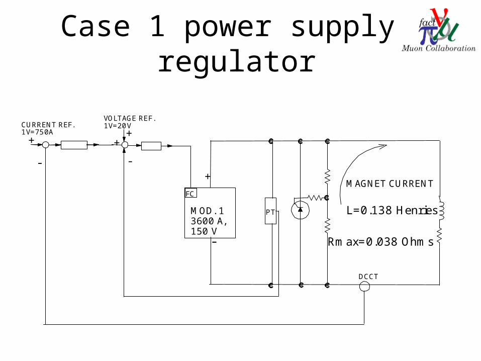
Case 1 power supply regulator
Rmax=0.038 Ohms-
+
MOD. 13600 A,150 V
+
-
+
-
+
PT
DCCT
VOLTAGE REF.1V=20VCURRENT REF.
1V=750A
L=0.138 Henries
MAGNET CURRENTFC

Case 2,3 power supply• Four series-parallel, 540 KVA power supplies rated at 3600 A, +/-150
V each, Total rating 7200A, +/-300V.
• Thyristor-control six-pulse rectifiers, available at Brookhaven Labs from previous experiments. (Model Meeker #431, in parallel with # 433, and #429, in parallel with # 432, )
• The power supplies are presently configured as DC power supplies.
• We need a new regulator to be able to pulse it,based on the existing design for the AGS Main magnet power supply.
• The controls and interlocks of the power supply must be updated.
• New direct current potential transformer (DCPT).
• New direct current current transformer (DCCT).
• New crowbar circuit to absorb magnet stored energy.
• Similar upgrades have been made during the Booster project with great success.

Case 2,3 power supply regulator
Rmax=0.038 Ohms
-
- -
-
+ +
+ +
MOD. 13600 A,150 V
MOD. 23600 A,150 V
MOD. 33600 A,150 V
MOD. 43600 A,150 V
MAGNET CURRENT
+
-
+
-
+
PT
PT
DCCT
VOLTAGE REF.1V=40V
CURRENT REF.1V=750A
L=0.45 Henries
FC FC
FC FC
+
1V=20V
1V=20V
+

More power supply details
• The 3-phase, 480-V input power to each supply will be fed from new, lockable disconnect switches.
• Each switch will be fed from an existing AC circuit breakers in an existing substation.
• Two parallel power supplies (MOD 1 and MOD 2) will be fed from the same existing substation and the other two (MOD 3 and MOD 4) from a different existing substation.
• The power supply will be fully programmable from 0 to 7200A. It will have two voltage regulators as the inner loops and a current regulator as the outer loop.
• The anticipated overall bus resistance should not exceed 1 m. 1 1/4 water cooled buss will be used we already have.
• All the old interlocks will be updated using an Allen Bradley Programmable Logic Controller (PLC).
• Minimum repetition rate for case1 magnet is 5 minutes, for case 2 magnet is 20 minutes, for case 3 magnet 30 minutes.

AC one line diagrams

Controls rack layout
PSI, VREF. MOD1,2 VREF. MOD3,4
PSI, IREF.
OFF STBY ON LOCAL CONTROLS
CPU V102TIMING
V108
READY PANEL TERMINAL600 TO MONITORINTERLOCKSBY ALEN BRADLEY
2 VOLTAGE REGULATORS (1 BOARD)1 CURRENT REGULATOR BOARD1 DRIVER/LINEARIZATION BOARD1 BUFFER BOARD1 POWER SUPPLY BOARD
PROGRAMMABLE LOGIC CONTROLERSLC 504 AND I/O MODULESBY ALLEN BRADLEY
BNC SIGNALS
WFGIREF.
WFGVREF.MOD1,2,3,4

Power supply interlocks• DC overcurrent
• RMS magnet current interlock
• AC overcurrent
• Blower failure
• Ground Fault
• Magnet faults
• Magnet resistance interlock.
• Cryo interlocks
• Doors are open
• SCR overtemperature
• SCR failure
• Power supply cubicle overtemperature
• Soft start overload
• Bus water flow and overtemperature

Power supply layout

Power supplies picture 1

Power supplies picture 2

Power supplies picture 3

Power supplies picture 4