e9 v2 for the cars equipped with can/lin bus make a
TRANSCRIPT
30 А+ 12 V
3 А
868 MHz transceivers
Bluetooth transceiver
X1
X2
X2
X3
X4
X5 USB-connector
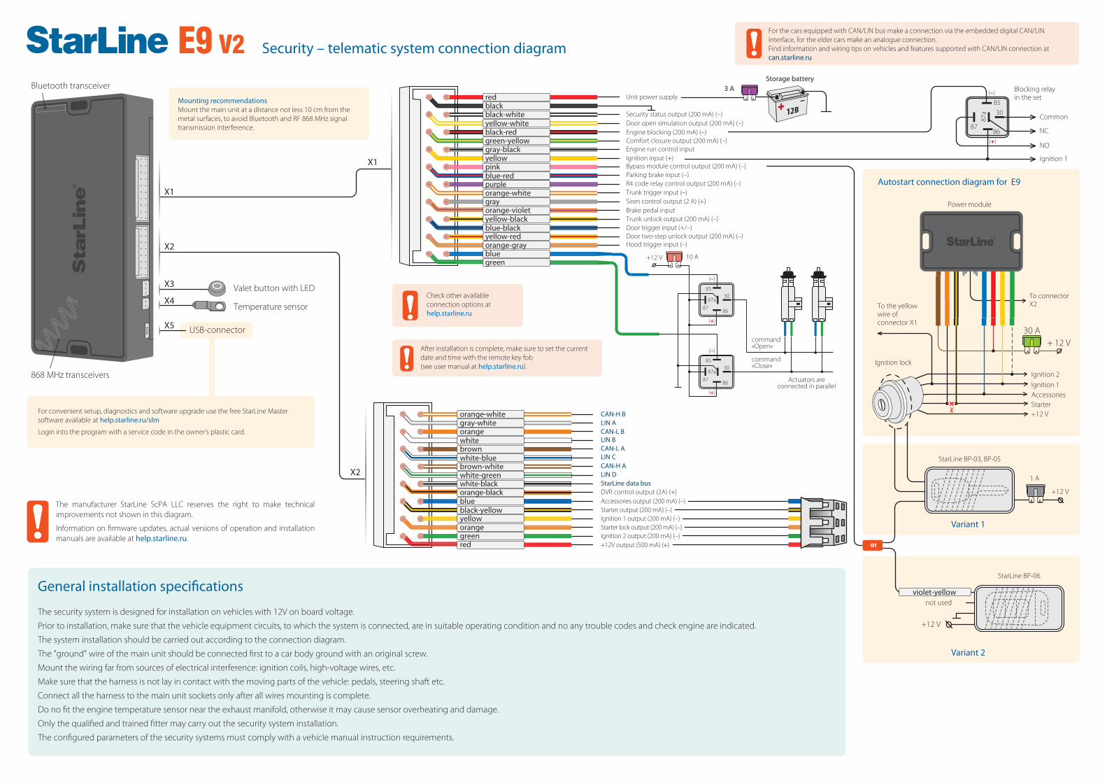
Autostart connection diagram for E9
+12 V
Ignition lock
Starter
Ignition 1Ignition 2
Accessories
+12 V
StarLine BP-03, BP-05
1 А
+12 V
StarLine BP-06
orange-violet
orange-white
blue-redpinkyellowgray-blackgreen-yellowblack-redyellow-whiteblack-whiteblackred
gray
green
orange-grayyellow-redblue-blackyellow-black
blue
X1
violet-yellownot used
Security – telematic system connection diagram
86
3085
87
87а
(–)
(+)
Variant 1
Variant 2
10 А
86
3085
8787а
86
3085
8787а
+12 V
(–)
(+)
(–)
(+)
Actuators areconnected in parallel
command«Close»
command«Open»
purple
Valet button with LED
Temperature sensor
For convenient setup, diagnostics and software upgrade use the free StarLine Master software available at help.starline.ru/slm
Login into the program with a service code in the owner’s plastic card.
Mounting recommendationsMount the main unit at a distance not less 10 cm from the metal surfaces, to avoid Bluetooth and RF 868 MHz signal transmission interference.
For the cars equipped with CAN/LIN bus make a connection via the embedded digital CAN/LIN interface, for the elder cars make an analogue connection.Find information and wiring tips on vehicles and features supported with CAN/LIN connection at can.starline.ru
Common
Blocking relay in the set
NC
NO
Ignition 1
Storage battery
Door open simulation output (200 mA) (–)
Unit power supply
Security status output (200 mA) (–)
Engine blocking (200 mA) (–)Comfort closure output (200 mA) (–)Engine run control inputIgnition input (+)Bypass module control output (200 mA) (–) Parking brake input (–)R4 code relay control output (200 mA) (–)Trunk trigger input (–)Siren control output (2 A) (+)Brake pedal inputTrunk unlock output (200 mA) (–)Door trigger input (+/–)Door two-step unlock output (200 mA) (–)Hood trigger input (–)
General installation speci�cations
The security system is designed for installation on vehicles with 12V on board voltage.
Prior to installation, make sure that the vehicle equipment circuits, to which the system is connected, are in suitable operating condition and no any trouble codes and check engine are indicated.
The system installation should be carried out according to the connection diagram.
The "ground" wire of the main unit should be connected first to a car body ground with an original screw.
Mount the wiring far from sources of electrical interference: ignition coils, high-voltage wires, etc.
Make sure that the harness is not lay in contact with the moving parts of the vehicle: pedals, steering shaft etc.
Connect all the harness to the main unit sockets only after all wires mounting is complete.
Do no fit the engine temperature sensor near the exhaust manifold, otherwise it may cause sensor overheating and damage.
Only the qualified and trained fitter may carry out the security system installation.
The configured parameters of the security systems must comply with a vehicle manual instruction requirements.
LIN ACAN-L BLIN BCAN-L A
CAN-H A
StarLine data busDVR control output (2А) (+)
CAN-H B
LIN C
LIN D
Accessories output (200 mA) (–)Starter output (200 mA) (–)Ignition 1 output (200 mA) (–)
Ignition 2 output (200 mA) (–)+12V output (500 mA) (+)
Starter lock output (200 mA) (–)
To connector X2To the yellow
wire of connector X1
Power module
orange-black
white-greenbrown-whitewhite-bluebrownwhiteorangegray-whiteorange-white
white-black
red
orangeyellowblack-yellowblue
green
E9 V2
After installation is complete, make sure to set the current date and time with the remote key fob (see user manual at help.starline.ru).
or
The manufacturer StarLine ScPA LLC reserves the right to make technical improvements not shown in this diagram.
Information on firmware updates, actual versions of operation and installation manuals are available at help.starline.ru.
Check other available connection options at help.starline.ru

Additional connection optionsCon�guring the security-telematic system
Version 2.13.2
1. In Starline Master program con�gure the blue output wire of X2 connector as “Simulation of the brake or clutch pedal”, and the black-yellow output wire of X2 connector - as “Engine start Start-Stop button”
2. Connect the wires according to the diagram
Diagram of starting circuit connection on cars with Push-to-Start button
Start relay module
+ 12 V30 A
+ 12 VBrake pedal switchBrake lights lamp
Start /Stop button
Do not connect
To the blue wire of X2 connector
To the black-yellowwire of X2 connector
To the red wire of X2 connector
Do not connect
Do not connect
Do not connect
Do not connect
Do not connect
Negative control pulse
STARTSTOP
E N G I N E
blue
Do not connect
Do not connect
black-yellowyellow
orange
redgreen
1. Disarm security system.2. Switch ignition O�, if it is On, then press service button 7 times.3. Switch ignition On.4. 7 LED �ashes of service button and 7 buzzer sounds will follow.5. Then 2 LED �ashes of service button and 2 buzzer sound signals will follow, con�rming entry into Registration mode.6. Enter the owner authorization code using car OEM buttons with a pressing interval no more than 3 seconds. Every button
pressing should be followed by a single service button LED �ash. The owner authorization code consists of a code sequence containing from 3 to 30 OEM buttons pressing. The list of supported
OEM buttons is available at can.starline.ru. If a service button LED �ash does not follow after pressing of OEM button, so this button is not supported for this car.
7. In 3 seconds after the code entry 2 short LED �ashes and 2 buzzer sound will follow, con�rming the code successful registration.8. Enter the owner authorization code again.9. If the code is recorded properly, 2 LED �ashes and 2 short buzzer sound will con�rm. If the code recording is failed, so 4 short
buzzer sounds will follow, in this case repeat steps 6-8.10. In 10 sec switch ignition O� to exit the Registration mode.11. An exit from Registration mode will be con�rmed by double LED �ashes and buzzer sounds and then additional signals in
amount of total registered tags, keys and smartphones will follow.12. Write down and memorize this entered Authorization code.
Entry in the device registration mode1. Disarm the security system.2. Switch ignition O� if it is On.3. Press the valet button 7 times.4. Switch ignition On. 7 light LED �ashes of service button and 7 buzzer sounds will follow.5. 2 short LED �ashes and buzzer sounds will con�rm entry into the Registration mode.
Remote key registration6. Press a remote key buttons 1 and 2 shortly.7. In 3 seconds successful registration will be con�rmed by a short beep sound of a remote key, 2 LED �ashes of a service button
and 2 buzzer sound signals. If a remote key is not registered, 4 beep sounds of a remote key will follow.8. Repeat points 6-7 for each remote key.
Bluetooth tags registration9. Remove a battery from a tag.10. Hold a tag button pressed and insert a battery back. A tag LED will turn red.11. Release a button, a series of red �ashes will follow.12. In 10 seconds successful registration will be con�rmed by a green LED �ash, 2 �ashes of a service button LED and 2 buzzer
sounds. If a tag is not registered LED will turn red.13. Repeat points 9-12 for all the remaining tags.
Smartphone registration14. Register a smartphone* with use of the free StarLine mobile App.
Exit from the device registration mode15. In 10 seconds switch ignition O� to exit the registration mode. An exit from Registration mode will be con�rmed by double
LED �ashes and buzzer sounds and then additional signals in amount of total registered tags, keys and smartphones will follow.
* The iOS and Android smartphone with Bluetooth Smart 4.2 and above are supported.
Programming an owner authorization code (with car buttons)
New devices registrationNOTE! At registration of new tags and smartphones all previously registered tags and smartphones will be erased from memory. So the existing devices should be registered simultaneously in one cycle with all the new devices. In total up to 5 Bluetooth devices can be registered in the system main unit. When new RF remote keys are registered, all previously registered remote keys will be erased from memory. So the existing remote keys should be registered simultaneously in one cycle with all the new remote keys.In total, up to 4 RF remote keys can be registered in the system main unit.
NOTE! The tags included in the delivery set are already registered in the main unit and are in the transport mode, i.e. o�. Pressing the tag button in this mode will be indicated by a green and red �ashes of the built-in LED. Prior to operation press the tag button several times until the LED color turn to green (regular mode).
10-50 kOhm
+12 V
Heater control unit
Pink
Yellow
Gray-black
Webasto heater connection with digital bus control
1. In StarLine Master software con�gure the pink output wire of X1 connector as “Webasto heater control via digital bus”, the gray-black wire – as “Webasto preheater start control via digital bus".
2. In “Engine start” section “Starting preheater” enable “Permission for preheater operation”. For the point “Start type of preheater” select option “Webasto via digital bus”.
3. Connect the wires according to the diagram.
10-50 kOhm
+12 V
Heater control unit
Pink
Blue-white
Eberspächer heater connection with digital bus control
1. In StarLine Master program con�gure the pink output wire of X1 connector as “Eberspacher preheater control via digital bus”.
2. In “Engine start” section “Starting preheater” enable “Permission for preheater operation”. For the point “Start type of preheater” select option “Eberspacher via digital bus”.
3. Connect the wires according to the diagram.
E9 V2