e5cze5cz e5cz-u e5aze5az e5eze5ez digital temperature
TRANSCRIPT
E5CZE5CZE5CZE5CZ-U
User's Manual
E5CZ-UE5CZ-UE5AZE5AZE5AZE5EZE5EZE5EZ
with 11-segment Display
Black
E5C
Z/CZ-U
/AZ/E
Z Digital Tem
perature Controller
User's M
anualH
207-E1-01
Digital Temperature Controller
Cat. No. H207-E1-01OMRON Industrial Automation Global:www.ia.omron.com Cat. No. H207-E1-01
OMRON CorporationIndustrial Automation CompanyControl Devices Division H.Q.Analog Controller DivisionShiokoji Horikawa, Shimogyo-ku,Kyoto, 600-8530 JapanTel: (81) 75-344-7080/Fax: (81) 75-344-71492-2-1 Nishikusalsu, Kusatsu-shi,Shiga, 525-0035 JapanTel: (81) 77-565-5216/Fax: (81) 77-565-5568
Regional HeadquartersOMRON EUROPE B.V.Wegalaan 67-69-2132 JD HoofddorpThe NetherlandsTel: (31) 2356-81-300/Fax: (31) 2356-81-388
OMRON ELECTRONICS LLCOne Commerce Drive Schaumburg, IL 60173-5302 U.S.A.Tel: (1) 847-843-7900/Fax: (1) 847-843-7787
OMRON ASIA PACIFIC PTE. LTD.No.438A Alexandra Road # 05-05/08 (Lobby 2), Alexandra Technopark, Singapore 119967Tel: (65)6835-3011/Fax: (65) 6835-2711
OMRON (CHINA) CO., LTDRoom 2211, Bank of China Tower,200 Yin Cheng Zhong Road ,Pu Dong New Area, Shanghai, 200120, ChinaTel: (86) 21-5037-2222/Fax: (86) 21-5037-2200
Authorized Distributor:
OMRON Corporation 2008 All Rights Reserved In the interest of product improvement,specitications are subject to change without notice.
C
Printed in China0908

E5CZ/E5CZ-U/E5AZ/E5EZDigital Temperature ControllerUser’s ManualProduced September 2008

iv

v
PrefaceOMRON products are manufactured for use according to proper procedures by a qualified operatorand only for the purposes described in this manual.The E5CZ, E5CZ-U, E5AZ, and E5EZ are Digital Temperature Controllers. The E5CZ and E5CZ-U areboth compact temperature controllers, with the E5CZ featuring screw terminal connections, and theE5CZ-U featuring socket pin connections. The main functions and characteristics of these Digital Tem-perature Controllers are as follows:
• Any of the following types of input can be used: thermocouple, platinumresistance thermometer, infrared sensor, analog voltage, or analog cur-rent.
• Depth of only 78mm• Either standard or heating/cooling control can be performed. • Both auto-tuning and self-tuning are supported.• Event inputs can be used to switch set points (multi-SP function), switch
between RUN and STOP status, and switch between automatic and man-ual operation. (Event input are not applicable to the E5CZ-U.)
• Heater burnout detection and HS alarms are supported. (Applicable toE5CZ, E5AZ, and E5EZ models with heater burnout detection function.)
• Communications are supported. (Applicable to E5CZ, E5AZ, and E5EZmodels with communications.)
• The structure of the E5CZ,E5AZ, and E5EZ is waterproof (IP66: indooruse). (Not applicable to the E5CZ-U).
• Conforms to UL, CSA, and IEC safety standards and EMC Directive.When using the E53-AZB, E53-AZ01 or E53-AZ03 Option Unit with theE5AZ-@3@M@@ to satisfy the immunity burst requirements in theEN61326 standard, always connect a ZCAT2035-0930 Clamlp Filter(manufactured by TDK) to the cable for terminals 11,12 and 13.
This manual describes the E5CZ, E5CZ-U, E5AZ, and E5EZ. Read this manual thoroughly and besure you understand it before attempting to use the Digital Temperature Controller and use the DigitalTemperature Controller correctly according to the information provided. Keep this manual in a safeplace for easy reference. Refer to the following manual for further information on communications:E5CZ/E5AZ/E5EZ Digital Temperature Controller Communications Manual (Cat. No. H208).
Visual AidsThe following headings appear in the left column of the manual to help you locate different types ofinformation.
Note Indicates information of particular interest for efficient and convenient opera-tion of the product.
1,2,3... 1. Indicates lists of one sort or another, such as procedures, checklists, etc.
© OMRON, 2008All rights reserved. No part of this publication may be reproduced, stored in a retrieval system, or transmitted, in any form, orby any means, mechanical, electronic, photocopying, recording, or otherwise, without the prior written permission ofOMRON.
No patent liability is assumed with respect to the use of the information contained herein. Moreover, because OMRON is con-stantly striving to improve its high-quality products, the information contained in this manual is subject to change withoutnotice. Every precaution has been taken in the preparation of this manual. Nevertheless, OMRON assumes no responsibilityfor errors or omissions. Neither is any liability assumed for damages resulting from the use of the information contained inthis publication.
vi
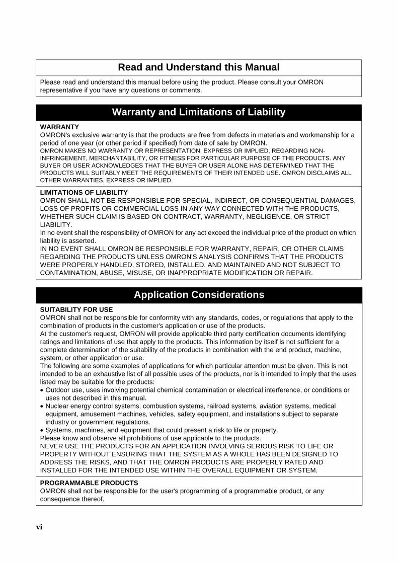
Read and Understand this ManualPlease read and understand this manual before using the product. Please consult your OMRON representative if you have any questions or comments.
Warranty and Limitations of LiabilityWARRANTYOMRON's exclusive warranty is that the products are free from defects in materials and workmanship for a period of one year (or other period if specified) from date of sale by OMRON.OMRON MAKES NO WARRANTY OR REPRESENTATION, EXPRESS OR IMPLIED, REGARDING NON-INFRINGEMENT, MERCHANTABILITY, OR FITNESS FOR PARTICULAR PURPOSE OF THE PRODUCTS. ANY BUYER OR USER ACKNOWLEDGES THAT THE BUYER OR USER ALONE HAS DETERMINED THAT THE PRODUCTS WILL SUITABLY MEET THE REQUIREMENTS OF THEIR INTENDED USE. OMRON DISCLAIMS ALL OTHER WARRANTIES, EXPRESS OR IMPLIED.
LIMITATIONS OF LIABILITYOMRON SHALL NOT BE RESPONSIBLE FOR SPECIAL, INDIRECT, OR CONSEQUENTIAL DAMAGES, LOSS OF PROFITS OR COMMERCIAL LOSS IN ANY WAY CONNECTED WITH THE PRODUCTS, WHETHER SUCH CLAIM IS BASED ON CONTRACT, WARRANTY, NEGLIGENCE, OR STRICT LIABILITY.In no event shall the responsibility of OMRON for any act exceed the individual price of the product on which liability is asserted. IN NO EVENT SHALL OMRON BE RESPONSIBLE FOR WARRANTY, REPAIR, OR OTHER CLAIMS REGARDING THE PRODUCTS UNLESS OMRON'S ANALYSIS CONFIRMS THAT THE PRODUCTS WERE PROPERLY HANDLED, STORED, INSTALLED, AND MAINTAINED AND NOT SUBJECT TO CONTAMINATION, ABUSE, MISUSE, OR INAPPROPRIATE MODIFICATION OR REPAIR.
Application ConsiderationsSUITABILITY FOR USEOMRON shall not be responsible for conformity with any standards, codes, or regulations that apply to the combination of products in the customer's application or use of the products.At the customer's request, OMRON will provide applicable third party certification documents identifying ratings and limitations of use that apply to the products. This information by itself is not sufficient for a complete determination of the suitability of the products in combination with the end product, machine, system, or other application or use.The following are some examples of applications for which particular attention must be given. This is not intended to be an exhaustive list of all possible uses of the products, nor is it intended to imply that the uses listed may be suitable for the products:• Outdoor use, uses involving potential chemical contamination or electrical interference, or conditions or
uses not described in this manual.• Nuclear energy control systems, combustion systems, railroad systems, aviation systems, medical
equipment, amusement machines, vehicles, safety equipment, and installations subject to separate industry or government regulations.
• Systems, machines, and equipment that could present a risk to life or property. Please know and observe all prohibitions of use applicable to the products.NEVER USE THE PRODUCTS FOR AN APPLICATION INVOLVING SERIOUS RISK TO LIFE OR PROPERTY WITHOUT ENSURING THAT THE SYSTEM AS A WHOLE HAS BEEN DESIGNED TO ADDRESS THE RISKS, AND THAT THE OMRON PRODUCTS ARE PROPERLY RATED AND INSTALLED FOR THE INTENDED USE WITHIN THE OVERALL EQUIPMENT OR SYSTEM.
PROGRAMMABLE PRODUCTS OMRON shall not be responsible for the user's programming of a programmable product, or any consequence thereof.

vii
DisclaimersCHANGE IN SPECIFICATIONSProduct specifications and accessories may be changed at any time based on improvements and other reasons.It is our practice to change model numbers when published ratings or features are changed, or when significant construction changes are made. However, some specifications of the products may be changed without any notice. When in doubt, special model numbers may be assigned to fix or establish key specifications for your application on your request. Please consult with your OMRON representative at any time to confirm actual specifications of purchased products.
DIMENSIONS AND WEIGHTS Dimensions and weights are nominal and are not to be used for manufacturing purposes, even when tolerances are shown.
PERFORMANCE DATA Performance data given in this manual is provided as a guide for the user in determining suitability and does not constitute a warranty. It may represent the result of OMRON's test conditions, and the users must correlate it to actual application requirements. Actual performance is subject to the OMRON Warranty and Limitations of Liability.
ERRORS AND OMISSIONSThe information in this document has been carefully checked and is believed to be accurate; however, no responsibility is assumed for clerical, typographical, or proofreading errors, or omissions.
viii
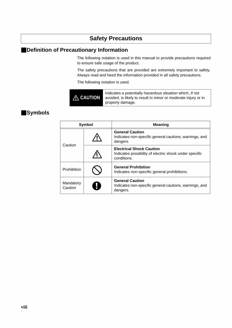
Definition of Precautionary InformationThe following notation is used in this manual to provide precautions requiredto ensure safe usage of the product.
The safety precautions that are provided are extremely important to safety.Always read and heed the information provided in all safety precautions.
The following notation is used.
Symbols
Safety Precautions
CAUTIONIndicates a potentially hazardous situation which, if not avoided, is likely to result in minor or moderate injury or in property damage.
Symbol Meaning
Caution
General Caution Indicates non-specific general cautions, warnings, and dangers.
Electrical Shock CautionIndicates possibility of electric shock under specific conditions.
Prohibition General ProhibitionIndicates non-specific general prohibitions.
Mandatory Caution
General CautionIndicates non-specific general cautions, warnings, and dangers.

ix
Safety Precautions
*1 A SELV circuit is one separated from the power supply with double insulation or reinforced insulation, thatdoes not exceed 30 V r.m.s. and 42.4 V peak or 60 VDC.
*2 A class 2 power supply is one tested and certified by UL as having the current and voltage of thesecondary output restricted to specific levels.
CAUTION
Do not touch the terminals while power is being supplied.Doing so may occasionally result in minor injury due to electric shock.
Do not allow pieces of metal, wire clippings, or fine metallic shav-ings or filings from installation to enter the product. Doing so may occasionally result in electric shock, fire, or malfunction.
Do not use the product where subject to flammable or explosive gas. Otherwise, minor injury from explosion may occasionally occur.
Never disassemble, modify, or repair the product or touch any of the internal parts. Minor electric shock, fire, or malfunction may occasionally occur.
CAUTION - Risk of Fire and Electric Shocka) This product is UL recognized as Open Type Process Control
Equipment. It must be mounted in an enclosure that does not allow fire to escape externally.
b) More than one disconnect switch may be required to de-energize the equipment before servicing the product.
c) Signal inputs are SELV, limited energy.*1d) Caution: To reduce the risk of fire or electric shock, do not inter-
connect the outputs of different Class 2circuits.*2
If the output relays are used past their life expectancy, contact fusing or burning may occasionally occur.Always consider the application conditions and use the output relays within their rated load and electrical life expectancy. The life expectancy of output relays varies considerably with the output load and switching conditions.

x
Note The tightening torque for E5CZ-U is 0.5 N·m.
CAUTION
Tighten the terminal screws to between 0.74 and 0.90 N·m. Loose screws may occasionally result in fire. (See note.)
Set the parameters of the product so that they are suitable for the system being controlled. If they are not suitable, unexpected operation may occasionally result in property damage or accidents.
A malfunction in the Temperature Controller may occasionally make control operations impossible or prevent alarm outputs, resulting in property damage. To maintain safety in the event of malfunction of the Temperature Controller, take appropriate safety measures, such as installing a monitoring device on a separate line.
When inserting the body of the Temperature Controller into the case,confirm that the hooks on the top and bottom are securely engaged with the case. If the body of the Temperature Controller is not inserted properly, faulty contact in the terminal section or reduced water resistance may occasionally result in fire or mal-function.

xi
Be sure to observe the following precautions to prevent operation failure, malfunction, or adverse affects onthe performance and functions of the product. Not doing so may occasionally result in unexpected events.1) The product is specifically designed for indoor use only. Do not use the product outdoors or in any of the
following places.• Places directly subject to heat radiated from heating equipment.• Places subject to splashing liquid or oil atmosphere.• Places subject to direct sunlight.• Places subject to dust or corrosive gas (in particular, sulfide gas and ammonia gas).• Places subject to intense temperature change.• Places subject to icing and condensation.• Places subject to vibration and large shocks.
2) Use and store the Digital Temperature Controller within the rated ambient temperature and humidity.Gang-mounting two or more temperature controllers, or mounting temperature controllers above eachother may cause heat to build up inside the temperature controllers, which will shorten their service life. Insuch a case, use forced cooling by fans or other means of air ventilation to cool down the DigitalTemperature Controllers.
3) To allow heat to escape, do not block the area around the product. Do not block the ventilation holes onthe product.
4) Be sure to wire properly with correct polarity of terminals.5) Use the specified size (M3.5, width 7.2 mm or less) crimped terminals for wiring. For open-wired
connection, use stranded or solid copper wires with a gage of AWG24 to AWG14 (equal to a cross-sectional area of 0.205 to 2.081 mm2). (The stripping length is 5 to 6 mm.) Up to two wires of the samesize and type or two crimp terminals can be inserted into a single terminal.
6) Do not wire the terminals which are not used.7) To avoid inductive noise, keep the wiring for the Digital Temperature Controller's terminal block away from
power cables carry high voltages or large currents. Also, do not wire power lines together with or parallelto Digital Temperature Controller wiring. Using shielded cables and using separate conduits or ducts isrecommended.Attach a surge suppressor or noise filter to peripheral devices that generate noise (in particular, motors,transformers, solenoids, magnetic coils or other equipment that have an inductance component).When a noise filter is used at the power supply, first check the voltage or current, and attach the noisefilter as close as possible to the temperature controller.Allow as much space as possible between the Digital Temperature Controller and devices that generatepowerful high frequencies (high-frequency welders, high-frequency sewing machines, etc.) or surge.
8) Use this product within the rated load and power supply.9) Make sure that the rated voltage is attained within 2 seconds of turning ON the power by using a switch or
relay contact. If the voltage is applied gradually, the power may not be reset or output malfunctions mayoccur.
10) Make sure that the Temperature Controller has 30 minutes or more to warm up after turning ON thepower before starting actual control operations to ensure the correct temperature display.
11) When executing self-tuning, turn ON power for the load (e.g., heater) at the same time as or beforesupplying power to the Digital Temperature Controller. If power is turned ON for the Digital TemperatureController before turning ON power for the load, self-tuning will not be performed properly and optimumcontrol will not be achieved.
12) A switch or circuit breaker should be provided close to this unit. The switch or circuit breaker should bewithin easy reach of the operator, and must be marked as a disconnecting means for this unit.
13) Always turn OFF the power supply before pulling out the interior of the product, and never touch nor applyshock to the terminals or electronic components. When inserting the interior of the product, do not allowthe electronic components to touch the case.
Precautions for Safe Use

xii
14) Do not use paint thinner or similar chemical to clean with. Use standard grade alcohol.15) Design system (control panel, etc) considering the 2 seconds of delay that the controller’s output to be set
after power ON.16) The output may turn OFF when shifting to certain levels. Take this into consideration when performing
control.17) The number of EEPROM write operations is limited. Therefore, use RAM write mode when frequently
overwriting data during communications or other operations.18) Always touch a grounded piece of metal before touching the Digital Temperature Controller to discharge
static electricity from your body.19) Control output that is voltage output is not isolated from the internal circuits.When using a grounded
thermocouple,do not connect any of the control output terminals to ground. (Doing so may result in anunwanted circuit path, causing error in the measured temperature.)
20) When replacing the body of the Digital Temperature Controller, check the condition of the terminals. Ifcorroded terminals are used, contact failure in the terminals may cause the temperature inside the DigitalTemperature Controller to increase, possibly resulting in fire. If the terminals are corroded, replace thecase as well.
21) Use suitable tools when taking the Digital Temperature Controller apart for disposal. Sharp parts inside theDigital Temperature Controller may cause injury.
22) Check the orientation of the connectors on the Conversion Cable before connecting the Conversion Cable.Do not force a connector if it does not connect smoothly. Using excessive force may damage theconnector.
23) Do not place heavy object on the Conversion Cable, bend the cable past its natural bending radius, or pullon the cable with undue force.
24) Do not connect or disconnect the Conversion Cable while communications are in progress. Product faultsor malfunction may occur.
25) Make sure that the Conversion Cable,s metal components are not touching the external power terminals.26) Do not touch the connectors on the Conversion Cable with wet hands. Electrical shock may result.
Service LifeUse the Temperature Controller within the following temperature and humidity ranges:Temperature: −10 to 55°C (with no icing or condensation), Humidity: 25% to 85%If the Controller is installed inside a control board, the ambient temperature must be kept to under 55°C,including the temperature around the Controller. The service life of electronic devices like Temperature Controllers is determined not only by the numberof times the relay is switched but also by the service life of internal electronic components. Componentservice life is affected by the ambient temperature: the higher the temperature, the shorter the servicelife and, the lower the temperature, the longer the service life. Therefore, the service life can beextended by lowering the temperature of the Temperature Controller. When two or more Temperature Controllers are mounted horizontally close to each other or verticallynext to one another, the internal temperature will increase due to heat radiated by the TemperatureControllers and the service life will decrease. In such a case, use forced cooling by fans or other meansof air ventilation to cool down the Temperature Controllers. When providing forced cooling, however, becareful not to cool down the terminals sections alone to avoid measurement errors.
Ambient NoiseTo avoid inductive noise, keep the wiring for the Digital Temperature Controller's terminal block wiringaway from power cables carrying high voltages or large currents. Also, do not wire power lines togetherwith or parallel to Digital Temperature Controller wiring. Using shielded cables and using separate con-duits or ducts is recommended.Attach a surge suppressor or noise filter to peripheral devices that generate noise (in particular, motors,transformers, solenoids, magnetic coils or other equipment that have an inductance component). Whena noise filter is used at the power supply, first check the voltage or current, and attach the noise filter asclose as possible to the Temperature Controller.Allow as much space as possible between the Digital Temperature Controller and devices that generatepowerful high frequencies (high-frequency welders, high-frequency sewing machines, etc.) or surge.
xiii
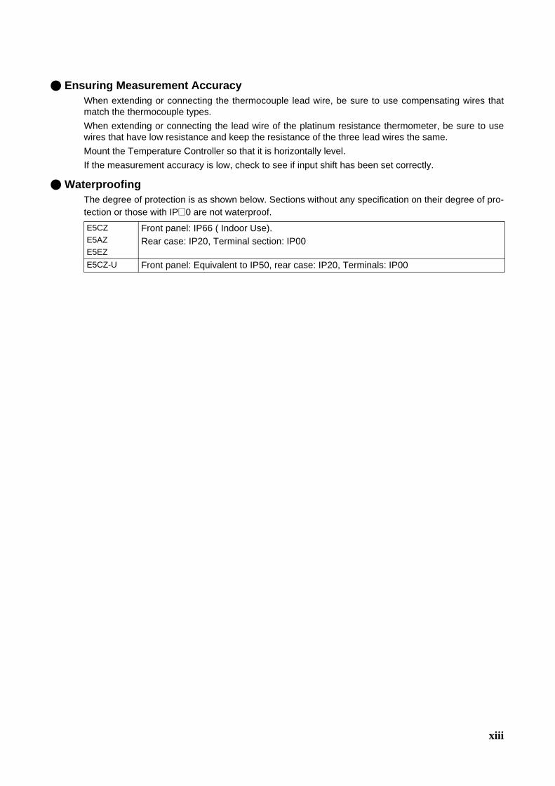
Ensuring Measurement AccuracyWhen extending or connecting the thermocouple lead wire, be sure to use compensating wires thatmatch the thermocouple types. When extending or connecting the lead wire of the platinum resistance thermometer, be sure to usewires that have low resistance and keep the resistance of the three lead wires the same. Mount the Temperature Controller so that it is horizontally level. If the measurement accuracy is low, check to see if input shift has been set correctly.
WaterproofingThe degree of protection is as shown below. Sections without any specification on their degree of pro-tection or those with IP@0 are not waterproof.
E5CZE5AZE5EZ
Front panel: IP66 ( Indoor Use).Rear case: IP20, Terminal section: IP00
E5CZ-U Front panel: Equivalent to IP50, rear case: IP20, Terminals: IP00

xiv
1) It takes approximately 2 seconds for the outputs to turn ON from after the power supply is turned ON. Dueconsideration must be given to this time when incorporating Temperature Controllers into a control panelor similar device.
2) Make sure that the Temperature Controller has 30 minutes or more to warm up after turning ON thepower before starting actual control operations to ensure the correct temperature display.
3) When executing self-tuning, turn ON power for the load (e.g., heater) at the same time as or beforesupplying power to the Temperature Controller. If power is turned ON for the Temperature Controllerbefore turning ON power for the load, self-tuning will not be performed properly and optimum control willnot be achieved. When starting operation after the Temperature Controller has warmed up, turn OFF thepower and then turn it ON again at the same time as turning ON power for the load. (Instead of turning theTemperature Controller OFF and ON again, switching from STOP mode to RUN mode can also be used.)
4) Avoid using the Controller in places near a radio, television set, or wireless installing. The Controller maycause radio disturbance for these devices.
Be sure to thoroughly read and understand the manual provided with the product, and check the fol-lowing points.
Note The tightening torque for E5CZ-U is 0.5 N·m.
Precautions for Operation
Preparations for Use
Timing Check point DetailsPurchasing the prod-uct
Product appearance After purchase, check that the product and packaging are not dented or otherwise damaged. Damaged internal parts may prevent optimum control.
Product model and speci-fications
Make sure that the purchased product meets the required specifica-tions.
Setting the Unit Product installation loca-tion
Provide sufficient space around the product for heat dissipation. Do not block the vents on the product.
Wiring Terminal wiring Do not subject the terminal screws to excessive stress (force) when tightening them.Make sure that there are no loose screws after tightening terminal screws to the specified torque of 0.74 to 0.90 N·m.(See note.)Be sure to confirm the polarity for each terminal before wiring the termi-nal block and connectors.
Power supply inputs Wire the power supply inputs correctly. Incorrect wiring will result in damage to the internal circuits.
Operating environ-ment
Ambient temperature The ambient operating temperature for the product is −10 to 55°C (with no condensation or icing). To extend the service life of the product, install it in a location with an ambient temperature as low as possible. In locations exposed to high temperatures, if necessary, cool the products using a fan or other cooling method.
Vibration and shock Check whether the standards related to shock and vibration are satis-fied at the installation environment. (Install the product in locations where the conductors will not be subject to vibration or shock.)
Foreign particles Install the product in a location that is not subject to liquid or foreign particles entering the product.

xv
The functions of the Controller have been upgraded in models manufactured in October 2008 or later. The designof the front panel can be used to differentiate between the previous and upgraded models.• E5CZ
• E5AZ/EZ
Other changes outlined in the following tables. Refer to relevant pages in the manual for details.
Previous models Improved function modelsE5CZ/CZ-U
E5AZ
E5EZ
ALM1ALM2HB
OUT1OUT2
STOPCMW
Upgraded Functions
The upgraded Controllers are basically compatible with the previous Controllers. Terminal arrangements, terminalsizes, and panel mounting depth have not been changed. The E5CZ-U plug-in type is newly released.
Although the upgraded Controllers are compatible with the previous Controllers, terminal arrangements have been
changed. Terminal sizes and panel mounting depth have not been changed.

xvi
RatingsItem Previous models Improved models
Power con-sumption
E5CZ 7 VA (100 to 240 VAC, 50/60 Hz) 4 VA/3 W (24 VAC, 50/60 Hz or 24 VDC)
7.5 VA (100 to 240 VAC, 50/60 Hz) 5.5 VA/3.5 W (24 VAC, 50/60 Hz or 24 VDC)
E5CZ-U (No models with plug-in type) 6 VA (100 to 240 VAC, 50/60 Hz)4.5 VA/2.5 W (24 VAC, 50/60 Hz or 24 VDC)
E5AZ 9 VA (100 to 240 VAC, 50/60 Hz)5 VA/4 W (24 VAC, 50/60 Hz or 24 VDC)
8.5 VA6 VA/4 W
E5EZ 9 VA (100 to 240 VAC, 50/60 Hz)5 VA/4 W (24 VAC, 50/60 Hz or 24 VDC)
8.5 VA6 VA/4 W
Sensor input (No models with analog inputs) E5@Z-@@@@L@(Models with analog inputs added.)Current input: 4 to 20 mA or 0 to 20 mAVoltage input: 1 to 5 V, 0 to 5 V, or 0 to 10 V

xvii
Control output 1
Relay E5CZ-R@@@SPST-NO, 250 VAC, 3 A (resistive load)Electrical life: 100,000 operations.
E5CZ-R@@@@SPST-NO, 250 VAC, 3 A (resistive load)Electrical life: 100,000 operations.
(No models with plug-in type) E5CZ-R@@@USPDT, 250 VAC, 3 A (resistive load)Electrical life: 100,000 operations.
E5AZ-R@@@SPST-NO, 250 VAC, 5 A (resistive load)Electrical life: 100,000 operations.
E5AZ-R@@@@@SPST-NO, 250 VAC, 5 A (resistive load)Electrical life: 100,000 operations.
E5EZ-R@@@SPST-NO, 250 VAC, 5 A (resistive load)Electrical life: 100,000 operations.
E5EZ-R@@@@@SPST-NO, 250 VAC, 5 A (resistive load)Electrical life: 100,000 operations.
Voltage E5CZ-Q@@@12 VDC ±15% (PNP)Max. load current: 21 mAWith short-circuit protection
E5CZ-Q@@@@12 VDC ±15% (PNP)Max. load current: 21 mAWith short-circuit protection
(No models with plug-in type) E5CZ-Q@@@U12 VDC ±15% (PNP)Max. load current: 21 mAWith short-circuit protection
E5AZ-Q@@@12 VDC +15%/−20% (PNP)Max. load current: 40 mAWith short-circuit protection
E5AZ-Q@@@@@12 VDC +15%/−20% (PNP)Max. load current: 40 mAWith short-circuit protection
E5EZ-Q@@@12 VDC +15%/−20% (PNP)Max. load current: 40 mAWith short-circuit protection
E5EZ-Q@@@@@12 VDC +15%/−20% (PNP)Max. load current: 40 mAWith short-circuit protection
Current E5CZ-C@@@4 to 20 mA DCLoad: 600 Ω max.Resolution: Approx. 2,600
E5CZ-C@@@@4 to 20 mA DC,0 to 20 mA DC. Load: 600 Ω max.Resolution: Approx. 2,700
E5AZ-C@@@4 to 20 mA DCLoad: 600 Ω max.Resolution: Approx. 2,600
E5AZ-C@@@@4 to 20 mA DC,0 to 20 mA DC. Load: 600 Ω max.Resolution: Approx. 2,700
E5EZ-C@@@4 to 20 mA DCLoad: 600 Ω max.Resolution: Approx. 2,600
E5EZ-C@@@@4 to 20 mA DC,0 to 20 mA DC. Load: 600 Ω max.Resolution: Approx. 2,700
Display method
E5CZ/CZ-U 7-segment digital display and single-LED indicators
11-segment digital display and single-LED indica-tor (Improved visibility)(A 7-segment digital display also possible.)
E5AZ/EZ 7-segment digital display and single-LED indicators
11-segment digital display and single-LED indica-tor (Improved visibility)(A 7-segment digital display also possible.)
Transfer output (No models with transfer outputs) E5@Z-C@@@@ Allocated to current output4 to 20 mA DC,0 to 20 mA DC. Load: 600 Ω max.Resolution: Approx. 2,700 (4 to 20 mA DC)
Item Previous models Improved models

xviii
Other Functions
Characteristics
Communications Specifications
Heater Burnout/HS Alarm Characteristics
Item Previous models Improved modelsDisplay --- Display character switch (7-segment/11-segment)Input Temperature input shift (1-point shift for temperature
input)Temperature input shift (2-point shift also possible for temperature input)
Output --- Manual outputs--- Loop break alarm
Control Control period: 1 to 99 s Control period: 0.5 or 1 to 99 sAlarm --- Alarm delays
Item Previous models Improved modelsSampling period 500 ms 250 ms
Item Previous models Improved modelsCommunications proto-cols
CompoWay/F (SYSWAY) CompoWay/F (SYSWAY), Modbus
Communications baud rate
1200, 2400, 4800, 9600, 19200 bps 1200, 2400, 4800, 9600, 19200, 38400 bps
Item Previous models Improved modelsMaximum heater current
E5CZ E5CZ-@@M@ with E53-CNH@NSingle-phase 50 A AC
E5CZ-@@M@@ with E53-CZH@Single-phase 50 A AC
E5AZ/EZ E5@Z-A3 + E53-AZM + E53-AZH,E5@Z-R3 + E53-AZM + E53-AZH,E5@Z-Q3 + E53-AZM + E53-AZHSingle-phase 50 A AC
E5@Z-@@H@@@Single-phase 50 A AC
HS alarm --- HS alarm

xix
Conventions Used in This Manual
Meanings of AbbreviationsThe following abbreviations are used in parameter names, figures and in text explanations. Theseabbreviations mean the following:
Note: (1) A heater short indicates that the heater remains ON even when the control output from the Temper-ature Controller is OFF because the SSR has failed or for any other reason.
(2) “EU” stands for Engineering Unit. EU is used as the minimum unit for engineering units such as °C,m, and g. The size of EU varies according to the input type. For example, when the input temperature setting range is –200 to +1300°C, 1 EU is 1°C, and whenthe input temperature setting range is –20.0 to +500.0°C, 1 EU is 0.1°C.For analog inputs, the size of EU varies according to the decimal point position of the scaling setting,and 1 EU becomes the minimum scaling unit.
Symbol TermPV Process valueSP Set pointSV Set valueAT Auto-tuningST Self-tuningHB Heater burnoutHS Heater short (See note 1.)LBA Loop burnout alarmEU Engineering unit (See note 2.)
xx
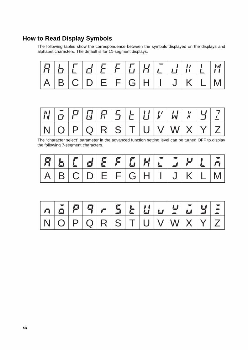
How to Read Display SymbolsThe following tables show the correspondence between the symbols displayed on the displays andalphabet characters. The default is for 11-segment displays.
The “character select” parameter in the advanced function setting level can be turned OFF to displaythe following 7-segment characters.
A B C D E F G H I J K L M
N O P Q R S T U V W X Y Z
a b c d e f g h i j k l m
n o p q r s t u v w x y z
A B C D E F G H I J K L M
N O P Q R S T U V W X Y Z

xxi
TABLE OF CONTENTSSECTION 1Introduction. . . . . . . . . . . . . . . . . . . . . . . . . . . . . . . . . . . . . . . 1
1-1 Names of Parts. . . . . . . . . . . . . . . . . . . . . . . . . . . . . . . . . . . . . . . . . . . . . . . . . . . . . . . . . . . . 2
1-2 I/O Configuration and Main Functions . . . . . . . . . . . . . . . . . . . . . . . . . . . . . . . . . . . . . . . . . 5
1-3 Setting Level Configuration and Key Operations . . . . . . . . . . . . . . . . . . . . . . . . . . . . . . . . . 10
1-4 Communications Function. . . . . . . . . . . . . . . . . . . . . . . . . . . . . . . . . . . . . . . . . . . . . . . . . . . 13
SECTION 2Preparations . . . . . . . . . . . . . . . . . . . . . . . . . . . . . . . . . . . . . . 15
2-1 Installation . . . . . . . . . . . . . . . . . . . . . . . . . . . . . . . . . . . . . . . . . . . . . . . . . . . . . . . . . . . . . . . 16
2-2 Wiring Terminals. . . . . . . . . . . . . . . . . . . . . . . . . . . . . . . . . . . . . . . . . . . . . . . . . . . . . . . . . . 21
2-3 Using the Support Software Port . . . . . . . . . . . . . . . . . . . . . . . . . . . . . . . . . . . . . . . . . . . . . . 27
SECTION 3Basic Operation. . . . . . . . . . . . . . . . . . . . . . . . . . . . . . . . . . . . 31
3-1 Initial Setting Examples. . . . . . . . . . . . . . . . . . . . . . . . . . . . . . . . . . . . . . . . . . . . . . . . . . . . . 32
3-2 Setting the Input Type . . . . . . . . . . . . . . . . . . . . . . . . . . . . . . . . . . . . . . . . . . . . . . . . . . . . . . 34
3-3 Selecting the Temperature Unit . . . . . . . . . . . . . . . . . . . . . . . . . . . . . . . . . . . . . . . . . . . . . . . 36
3-4 Selecting PID Control or ON/OFF Control . . . . . . . . . . . . . . . . . . . . . . . . . . . . . . . . . . . . . . 36
3-5 Setting Output Specifications . . . . . . . . . . . . . . . . . . . . . . . . . . . . . . . . . . . . . . . . . . . . . . . . 36
3-6 Setting the Set Point (SP) . . . . . . . . . . . . . . . . . . . . . . . . . . . . . . . . . . . . . . . . . . . . . . . . . . . 40
3-7 Using ON/OFF Control . . . . . . . . . . . . . . . . . . . . . . . . . . . . . . . . . . . . . . . . . . . . . . . . . . . . . 40
3-8 Determining PID Constants (AT, ST, Manual Setup). . . . . . . . . . . . . . . . . . . . . . . . . . . . . . 43
3-9 Alarm Outputs . . . . . . . . . . . . . . . . . . . . . . . . . . . . . . . . . . . . . . . . . . . . . . . . . . . . . . . . . . . . 47
3-10 Using HB and HS Alarms . . . . . . . . . . . . . . . . . . . . . . . . . . . . . . . . . . . . . . . . . . . . . . . . . . . 50
SECTION 4Applications Operations. . . . . . . . . . . . . . . . . . . . . . . . . . . . . 57
4-1 Shifting Input Values. . . . . . . . . . . . . . . . . . . . . . . . . . . . . . . . . . . . . . . . . . . . . . . . . . . . . . . 59
4-2 Alarm Hysteresis . . . . . . . . . . . . . . . . . . . . . . . . . . . . . . . . . . . . . . . . . . . . . . . . . . . . . . . . . . 63
4-3 Setting Scaling Upper and Lower Limits for Analog Inputs. . . . . . . . . . . . . . . . . . . . . . . . . 65
4-4 Executing Heating/Cooling Control . . . . . . . . . . . . . . . . . . . . . . . . . . . . . . . . . . . . . . . . . . . 66
4-5 Using Event Inputs . . . . . . . . . . . . . . . . . . . . . . . . . . . . . . . . . . . . . . . . . . . . . . . . . . . . . . . . 69
4-6 Setting the SP Upper and Lower Limit Values . . . . . . . . . . . . . . . . . . . . . . . . . . . . . . . . . . . 73
4-7 Using the SP Ramp Function to Limit the SP Change Rate . . . . . . . . . . . . . . . . . . . . . . . . . 74
4-8 Moving to the Advanced Function Setting Level . . . . . . . . . . . . . . . . . . . . . . . . . . . . . . . . . 76
4-9 Using the Key Protect Level . . . . . . . . . . . . . . . . . . . . . . . . . . . . . . . . . . . . . . . . . . . . . . . . . 77
4-10 Alarm Delays . . . . . . . . . . . . . . . . . . . . . . . . . . . . . . . . . . . . . . . . . . . . . . . . . . . . . . . . . . . . . 79
4-11 Loop Break Alarm . . . . . . . . . . . . . . . . . . . . . . . . . . . . . . . . . . . . . . . . . . . . . . . . . . . . . . . . . 81
4-12 Performing Manual Control. . . . . . . . . . . . . . . . . . . . . . . . . . . . . . . . . . . . . . . . . . . . . . . . . . 84
4-13 Using the Transfer Output . . . . . . . . . . . . . . . . . . . . . . . . . . . . . . . . . . . . . . . . . . . . . . . . . . . 88
4-14 Output Adjustment Functions . . . . . . . . . . . . . . . . . . . . . . . . . . . . . . . . . . . . . . . . . . . . . . . . 91

xxii
TABLE OF CONTENTSSECTION 5Parameters. . . . . . . . . . . . . . . . . . . . . . . . . . . . . . . . . . . . . . . . 93
5-1 Conventions Used in this Section . . . . . . . . . . . . . . . . . . . . . . . . . . . . . . . . . . . . . . . . . . . . . 94
5-2 Protect Level . . . . . . . . . . . . . . . . . . . . . . . . . . . . . . . . . . . . . . . . . . . . . . . . . . . . . . . . . . . . . 95
5-3 Operation Level . . . . . . . . . . . . . . . . . . . . . . . . . . . . . . . . . . . . . . . . . . . . . . . . . . . . . . . . . . . 97
5-4 Adjustment Level. . . . . . . . . . . . . . . . . . . . . . . . . . . . . . . . . . . . . . . . . . . . . . . . . . . . . . . . . . 106
5-5 Manual Control Level . . . . . . . . . . . . . . . . . . . . . . . . . . . . . . . . . . . . . . . . . . . . . . . . . . . . . . 117
5-6 Initial Setting Level . . . . . . . . . . . . . . . . . . . . . . . . . . . . . . . . . . . . . . . . . . . . . . . . . . . . . . . . 118
5-7 Advanced Function Setting Level . . . . . . . . . . . . . . . . . . . . . . . . . . . . . . . . . . . . . . . . . . . . . 129
5-8 Communications Setting Level . . . . . . . . . . . . . . . . . . . . . . . . . . . . . . . . . . . . . . . . . . . . . . . 149
Appendix A . . . . . . . . . . . . . . . . . . . . . . . . . . . . . . . . . . . . . . . 151
Index. . . . . . . . . . . . . . . . . . . . . . . . . . . . . . . . . . . . . . . . . . . . . 177
Revision History . . . . . . . . . . . . . . . . . . . . . . . . . . . . . . . . . . . 183
xxiii
About this Manual:
This manual describes the E5CZ/CZ-U/AZ/EZ Digital Temperature Controllers and includes the sec-tions described below.
Please read this manual carefully and be sure you understand the information provided before attempting to set up or operate an E5CZ/CZ-U/AZ/EZ Digital Temperature Controller.
• OverviewSection 1 introduces the features, components, and main specifications of the E5CZ/CZ-U/AZ/EZ Dig-ital Temperature Controllers.
• SetupSection 2 describes the work required to prepare the E5CZ/CZ-U/AZ/EZ Digital Temperature Control-lers for operation, including installation and wiring.
• Basic OperationsSection 3 describes the basic operation of the E5CZ/CZ-U/AZ/EZ Digital Temperature Controllers, including key operations to set parameters and descriptions of display elements based on specific con-trol examples.
Section 5 describes the individual parameters used to set up, control, and monitor operation.
• Operations for ApplicationsSection 4 describes scaling, the SP ramp function, and other special functions that can be used to make the most of the functionality of the E5CZ/CZ-U/AZ/EZ Digital Temperature Controllers.
Section 5 describes the individual parameters used to setup, control, and monitor operation.
• AppendicesThe Appendix provides information for easy reference, including lists of parameters and settings.
!WARNING Failure to read and understand the information provided in this manual may result in per-sonal injury or death, damage to the product, or product failure. Please read each section in its entirety and be sure you understand the information provided in the section and related sections before attempting any of the procedures or operations given.

xxiv
1
SECTION 1Introduction
This section introduces the features, components, and main specifications of the E5CZ and E5CZ-U Digital TemperatureControllers.
1-1 Names of Parts . . . . . . . . . . . . . . . . . . . . . . . . . . . . . . . . . . . . . . . . . . . . . . . . 2
1-1-1 Front Panel . . . . . . . . . . . . . . . . . . . . . . . . . . . . . . . . . . . . . . . . . . . . 2
1-1-2 Meanings of Indicators . . . . . . . . . . . . . . . . . . . . . . . . . . . . . . . . . . . 3
1-1-3 Using the Keys . . . . . . . . . . . . . . . . . . . . . . . . . . . . . . . . . . . . . . . . . 4
1-2 I/O Configuration and Main Functions . . . . . . . . . . . . . . . . . . . . . . . . . . . . . . 5
1-2-1 I/O Configuration . . . . . . . . . . . . . . . . . . . . . . . . . . . . . . . . . . . . . . . 5
1-2-2 Main Functions . . . . . . . . . . . . . . . . . . . . . . . . . . . . . . . . . . . . . . . . . 8
1-3 Setting Level Configuration and Key Operations. . . . . . . . . . . . . . . . . . . . . . 10
1-3-1 Selecting Parameters. . . . . . . . . . . . . . . . . . . . . . . . . . . . . . . . . . . . . 12
1-3-2 Fixing Settings . . . . . . . . . . . . . . . . . . . . . . . . . . . . . . . . . . . . . . . . . 12
1-4 Communications Function . . . . . . . . . . . . . . . . . . . . . . . . . . . . . . . . . . . . . . . 13
2
Names of Parts Section 1-1
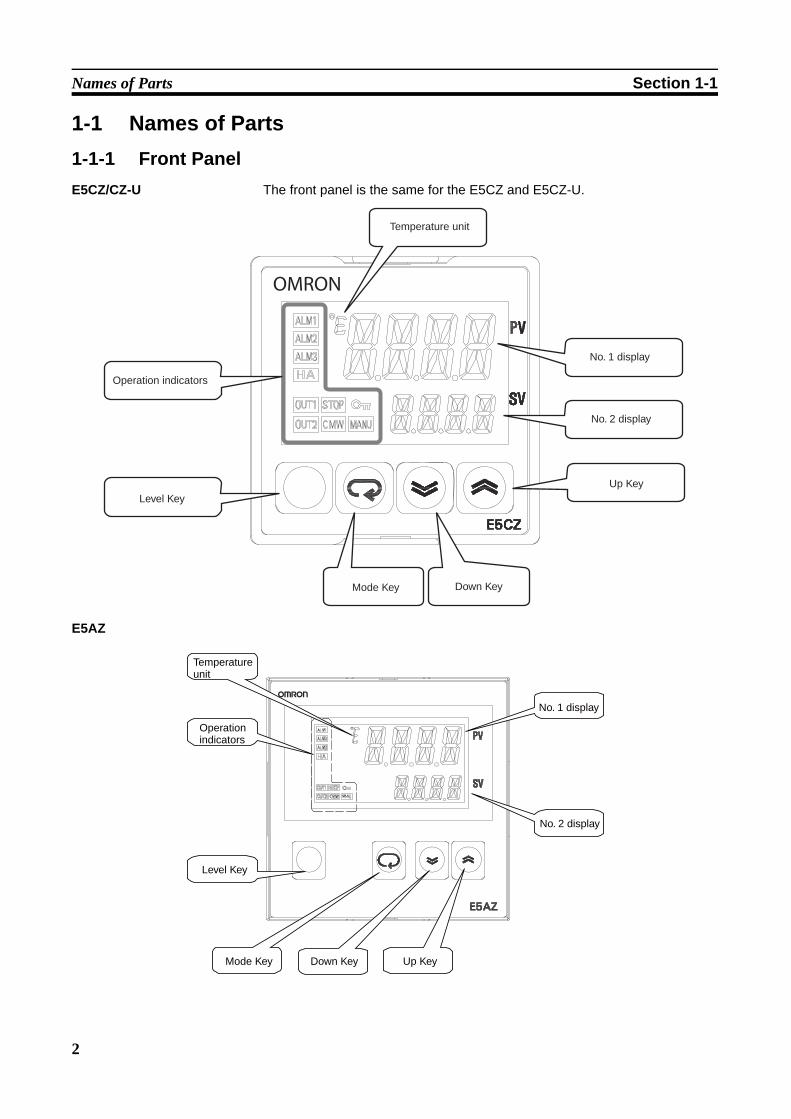
1-1 Names of Parts1-1-1 Front PanelE5CZ/CZ-U The front panel is the same for the E5CZ and E5CZ-U.
E5AZ
OMRON
Temperature unit
No. 1 display
No. 2 display
Up Key
Mode Key Down Key
Level Key
Operation indicators
No. 1 display
No. 2 display
Mode Key Up Key
Level Key
Down Key
Temperature unit
Operation indicators
3
Names of Parts Section 1-1
E5EZ
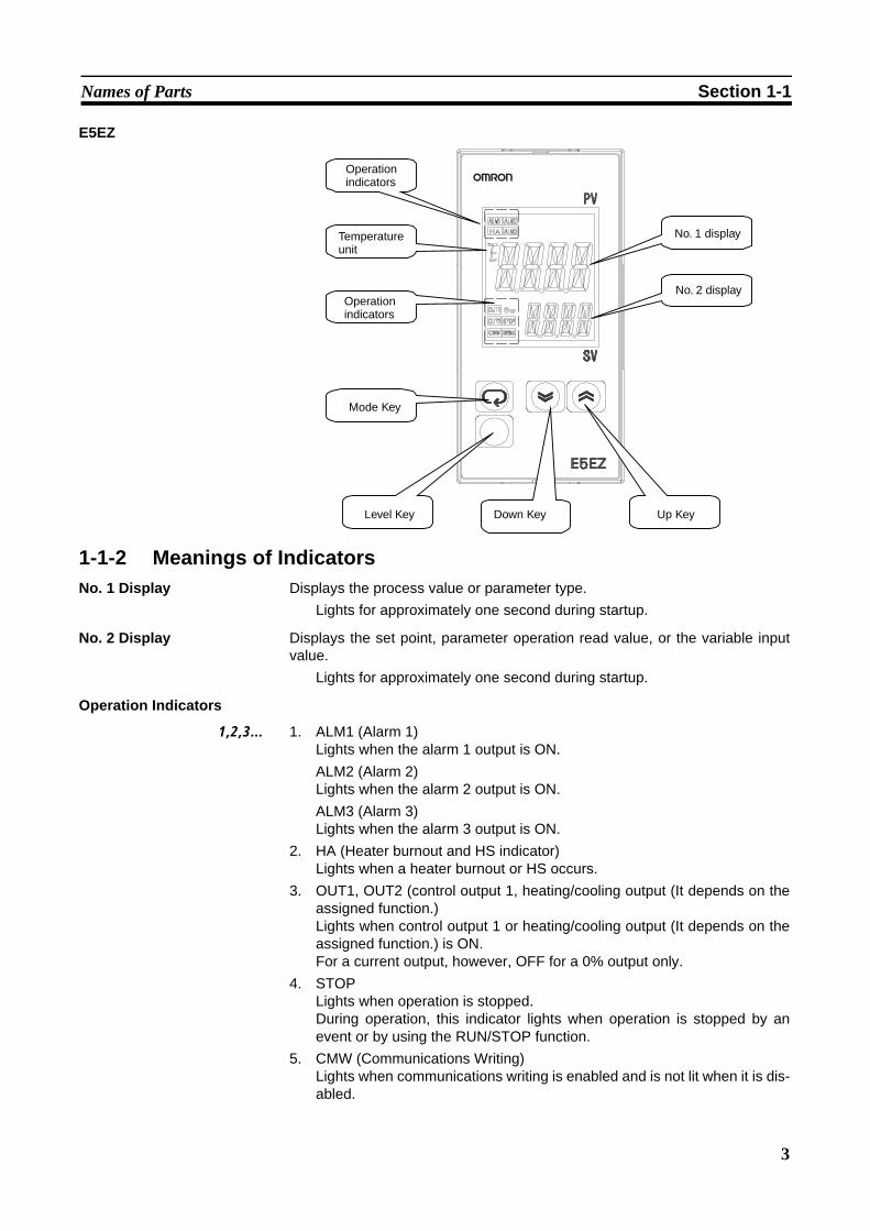
1-1-2 Meanings of IndicatorsNo. 1 Display Displays the process value or parameter type.
Lights for approximately one second during startup.
No. 2 Display Displays the set point, parameter operation read value, or the variable inputvalue.
Lights for approximately one second during startup.
Operation Indicators
1,2,3... 1. ALM1 (Alarm 1)Lights when the alarm 1 output is ON.ALM2 (Alarm 2)Lights when the alarm 2 output is ON.ALM3 (Alarm 3)Lights when the alarm 3 output is ON.
2. HA (Heater burnout and HS indicator)Lights when a heater burnout or HS occurs.
3. OUT1, OUT2 (control output 1, heating/cooling output (It depends on theassigned function.)Lights when control output 1 or heating/cooling output (It depends on theassigned function.) is ON.For a current output, however, OFF for a 0% output only.
4. STOPLights when operation is stopped.During operation, this indicator lights when operation is stopped by anevent or by using the RUN/STOP function.
5. CMW (Communications Writing)Lights when communications writing is enabled and is not lit when it is dis-abled.
Operation indicators
Temperature unit
Operation indicators
Mode Key
Level Key Down Key Up Key
No. 1 display
No. 2 display
4
Names of Parts Section 1-1
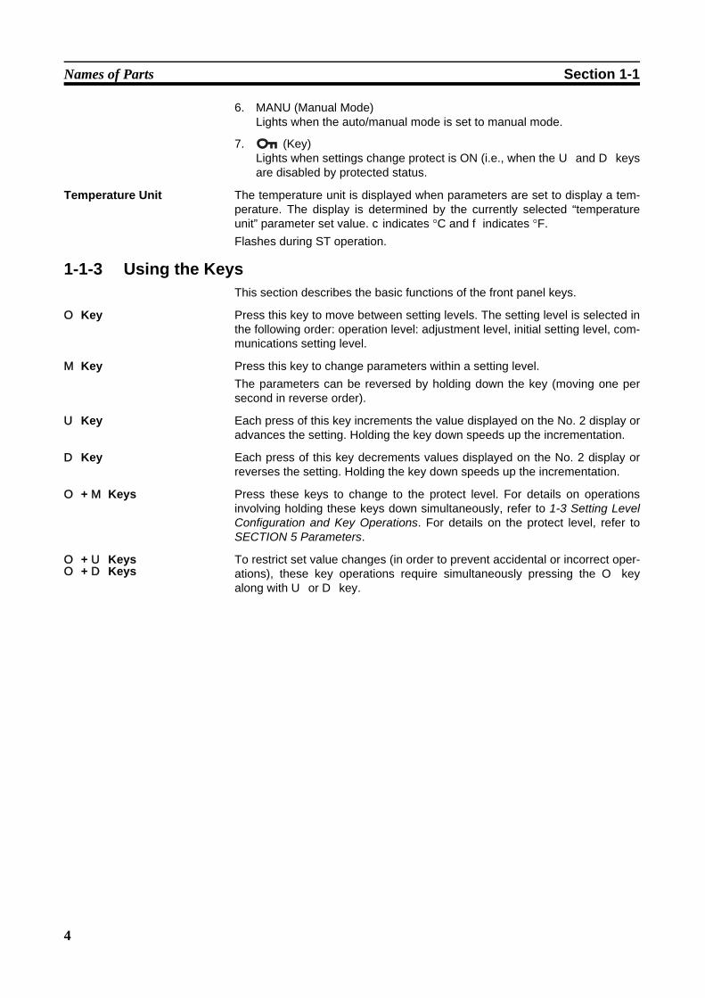
6. MANU (Manual Mode)Lights when the auto/manual mode is set to manual mode.
7. (Key)Lights when settings change protect is ON (i.e., when the U and D keysare disabled by protected status.
Temperature Unit The temperature unit is displayed when parameters are set to display a tem-perature. The display is determined by the currently selected “temperatureunit” parameter set value. c indicates °C and f indicates °F.Flashes during ST operation.
1-1-3 Using the KeysThis section describes the basic functions of the front panel keys.
O Key Press this key to move between setting levels. The setting level is selected inthe following order: operation level: adjustment level, initial setting level, com-munications setting level.
M Key Press this key to change parameters within a setting level.The parameters can be reversed by holding down the key (moving one persecond in reverse order).
U Key Each press of this key increments the value displayed on the No. 2 display oradvances the setting. Holding the key down speeds up the incrementation.
D Key Each press of this key decrements values displayed on the No. 2 display orreverses the setting. Holding the key down speeds up the incrementation.
O + M Keys Press these keys to change to the protect level. For details on operationsinvolving holding these keys down simultaneously, refer to 1-3 Setting LevelConfiguration and Key Operations. For details on the protect level, refer toSECTION 5 Parameters.
O + U KeysO + D Keys
To restrict set value changes (in order to prevent accidental or incorrect oper-ations), these key operations require simultaneously pressing the O keyalong with U or D key.
5
I/O Configuration and Main Functions Section 1-2
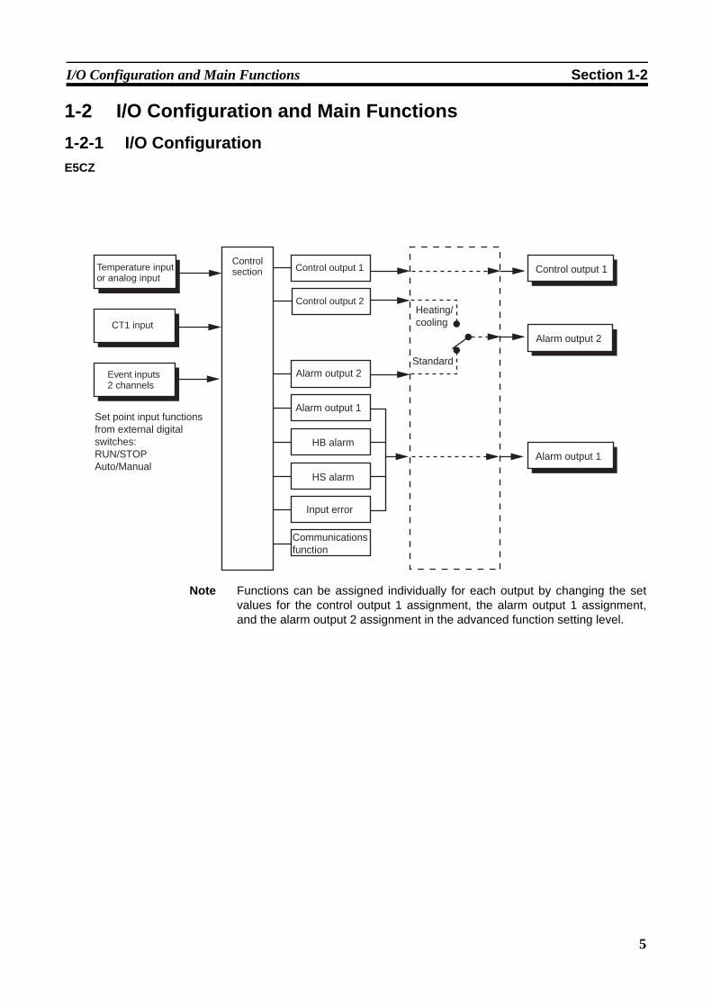
1-2 I/O Configuration and Main Functions1-2-1 I/O ConfigurationE5CZ
Note Functions can be assigned individually for each output by changing the setvalues for the control output 1 assignment, the alarm output 1 assignment,and the alarm output 2 assignment in the advanced function setting level.
Temperature input or analog input
CT1 input
Event inputs2 channels
Control section Control output 1
Alarm output 1
Control output 1
HB alarm
HS alarm
Input error
Communications function
Alarm output 1
Set point input functions from external digital switches: RUN/STOPAuto/Manual
Control output 2
Alarm output 2
Heating/cooling
Alarm output 2
Standard
6
I/O Configuration and Main Functions Section 1-2
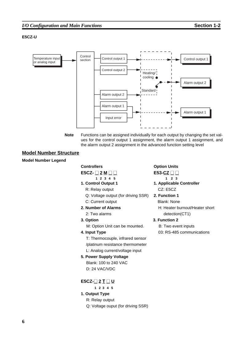
E5CZ-U
Note Functions can be assigned individually for each output by changing the set val-ues for the control output 1 assignment, the alarm output 1 assignment, andthe alarm output 2 assignment in the advanced function setting level
Model Number StructureModel Number Legend
Controllers Option UnitsE5CZ- @ 2 M @ @ E53-CZ @ @ 1 2 3 4 5 1 2 31. Control Output 1 1. Applicable Controller
R: Relay output CZ: E5CZQ: Voltage output (for driving SSR) 2. Function 1C: Current output Blank: None
2. Number of Alarms H: Heater burnout/Heater short2: Two alarms detection(CT1)
3. Option 3. Function 2M: Option Unit can be mounted. B: Two event inputs
4. Input Type 03: RS-485 communicationsT: Thermocouple, infrared sensor /platinum resistance thermometerL: Analog current/voltage input
5. Power Supply VoltageBlank: 100 to 240 VACD: 24 VAC/VDC
E5CZ-@ 2 T @ U 1 2 3 4 5
1. Output TypeR: Relay outputQ: Voltage ouput (for driving SSR)
Temperature input or analog input
Control section Control output 1
Control output 2
Alarm output 1
Alarm output 2
Control output 1
Input error
Heating/cooling
Alarm output 1
Alarm output 2
Standard
7
I/O Configuration and Main Functions Section 1-2
2. Number of Alarms2: Two alarms
3. Input TypeT: Thermocouple, infrared sensor
/platinum resistance thermometer4. Power Supply Voltage
Blank: 100 to 240 VACD: 24 VAC/VDC
5. Plug-in typeU: Plug-in type
Note Not all combinations of function 1 and function 2 specifications are possiblefor Option Units (E53-CZ@@).
A functional explanation is provided here for illustration, but models are notnecessarily available for all possible combinations. Refer to the catalog whenordering.Examples:Communications function E5CZ-@2MT with E53-CZ03Alarm output (with 2 alarm outputs, HB alarm, and event inputs): E5CZ-@2MT with E53-CZHB
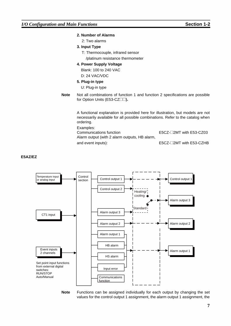
E5AZ/EZ
Note Functions can be assigned individually for each output by changing the setvalues for the control output 1 assignment, the alarm output 1 assignment, the
Temperature input or analog input
Control section
CT1 input
Event inputs2 channels
Set point input functions from external digital switches: RUN/STOPAuto/Manual
Control output 1
Control output 2
Alarm output 3
Alarm output 1
Alarm output 2
HB alarm
HS alarm
Input error
Communications function
Control output 1
Alarm output 1
Alarm output 2
Alarm output 3
Heating/cooling
Standard
8
I/O Configuration and Main Functions Section 1-2
alarm output 2 assignment, and the alarm output 3 assignment in theadvanced function setting level.
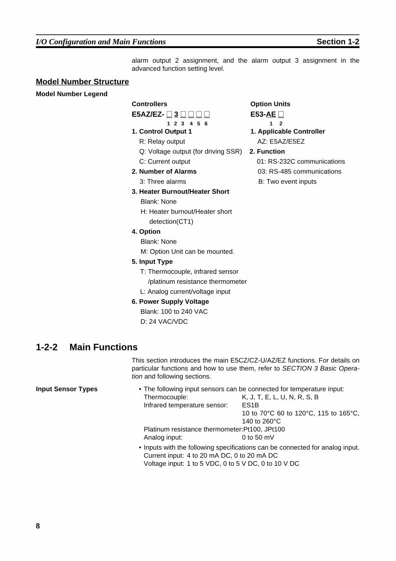
Model Number StructureModel Number Legend
Controllers Option UnitsE5AZ/EZ- @ 3 @ @ @ @ E53-AE @ 1 2 3 4 5 6 1 21. Control Output 1 1. Applicable Controller
R: Relay output AZ: E5AZ/E5EZQ: Voltage output (for driving SSR) 2. FunctionC: Current output 01: RS-232C communications
2. Number of Alarms 03: RS-485 communications3: Three alarms B: Two event inputs
3. Heater Burnout/Heater Short Blank: None H: Heater burnout/Heater short
detection(CT1)4. Option
Blank: NoneM: Option Unit can be mounted.
5. Input TypeT: Thermocouple, infrared sensor
/platinum resistance thermometerL: Analog current/voltage input
6. Power Supply VoltageBlank: 100 to 240 VACD: 24 VAC/VDC
1-2-2 Main FunctionsThis section introduces the main E5CZ/CZ-U/AZ/EZ functions. For details onparticular functions and how to use them, refer to SECTION 3 Basic Opera-tion and following sections.
Input Sensor Types • The following input sensors can be connected for temperature input:Thermocouple: K, J, T, E, L, U, N, R, S, BInfrared temperature sensor: ES1B
10 to 70°C 60 to 120°C, 115 to 165°C,140 to 260°C
Platinum resistance thermometer:Pt100, JPt100Analog input: 0 to 50 mV
• Inputs with the following specifications can be connected for analog input.Current input: 4 to 20 mA DC, 0 to 20 mA DCVoltage input: 1 to 5 VDC, 0 to 5 V DC, 0 to 10 V DC

9
I/O Configuration and Main Functions Section 1-2
Control Outputs • A control output can be relay, voltage, or current output, depending on themodel.
• With the E5CZ-@2M@@, alarm output 2 is used as control output (cool-ing) when heating/cooling control is selected. Therefore, use alarm 1 if analarm is required while using heating/cooling control.
• With the E5AZ/E5EZ-@3@@@@, alarm output 3 is used as control output(cooling) when heating/cooling control is selected. Therefore, use alarms1 and 2 if an alarm is required while using heating/cooling control.
Alarms • Alarms can be used with the E5CZ-@2M@@,or E5CZ-@2T@U. Set thealarm classification and alarm value or the alarm's upper and lower limits.
• If necessary, a more comprehensive alarm function can be achieved bysetting the standby sequence, alarm hysteresis, close in alarm/open inalarm, and alarm latch parameters.
• When the “input error output” parameter is set to ON, alarm output 1 turnsON when an input error occurs.
Control Adjustment • Optimum PID constants can be set easily by performing AT (auto-tuning)or ST (self-tuning).
Event Inputs • The following functions can be executed using event inputs: switching setpoints (multi-SP, 4 pts. max.), and switching RUN/STOP status, andswitching between automatic and manual operation.E5CZ-@2M@@ with E53-CZB or E53-CZHB E5AZ-@3@M@@ with E53-AZBE5EZ-@3@M@@ with E53-AZB
Heater Burnout and HS Alarms
• The heater burnout detection function and the HS alarm function can beused.E5CZ-@2M@@ with E53-CZH03 or E53-CZHBE5AZ-@3HM@@E5EZ-@3HM@@
Communications Functions
• Communications functions utilizing CompoWay/F (See note 1.), SYSWAY (See note 2.), or Modbus (See note 3.) can be used.RS-485 InterfaceE5CZ-@2M@@ with E53-CZH03 or E53-CZ03 E5AZ-@3@M@@ with E53-AZ03 E5EZ-@3@M@@ with E53-AZ03 RS-232C Interface.(See note 4.)E5AZ-@3@M@@ with E53-AZ01 E5EZ-@3@M@@ with E53-AZ01
Note (1) CompoWay/F is an integrated general-purpose serial communicationsprotocol developed by OMRON. It uses commands compliant with thewell-established FINS, together with a consistent frame format on OMRON Programmable Controllers to facilitate communications be-tween personal computers and components.
(2) SYSWAY communications do not support alarm 3 output.(3) Modbus is a communications control method conforming to the RTU
Mode of Modicon Inc.'s Modbus Protocol.(4) The E5CZ and E5CZ-U do not support the RS-232C interface.
10
Setting Level Configuration and Key Operations Section 1-3
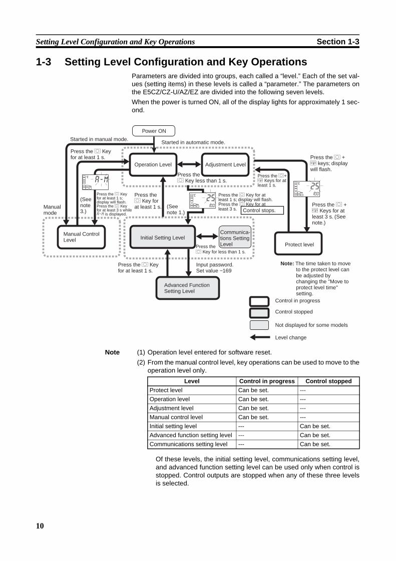
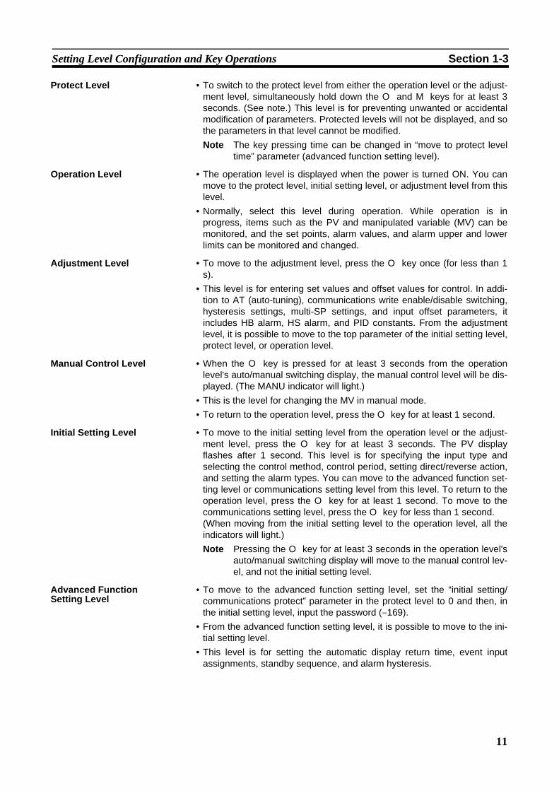
1-3 Setting Level Configuration and Key OperationsParameters are divided into groups, each called a “level.” Each of the set val-ues (setting items) in these levels is called a “parameter.” The parameters onthe E5CZ/CZ-U/AZ/EZ are divided into the following seven levels.When the power is turned ON, all of the display lights for approximately 1 sec-ond.
Note (1) Operation level entered for software reset.(2) From the manual control level, key operations can be used to move to the
operation level only.
Of these levels, the initial setting level, communications setting level,and advanced function setting level can be used only when control isstopped. Control outputs are stopped when any of these three levelsis selected.
(See note 3.)
(See note 1.)
Power ON
Started in manual mode.
Manual mode
Press the O Key for at least 1 s.
Press the O Key for at least 1 s; display will flash.Press the O Key for at least 3 s while a-m is displayed.
Manual Control Level
Operation Level
Press the O Key for at least 1 s.
Initial Setting Level
Press the O Key for at least 1 s.
Advanced Function Setting Level
Input password. Set value −169
Press the O Key less than 1 s.
Communica-tions Setting Level
Press the O Key for at least 1 s; display will flash.Press the O Key for at least 3 s. Control stops.
Press the O Key for less than 1 s.
Adjustment Level
Press the O+ M Keys for at least 1 s.
Press the O + M keys; display will flash.
Press the O + M Keys for at least 3 s. (See note.)
Protect level
Note: The time taken to move to the protect level can be adjusted by changing the "Move to protect level time" setting.
Control in progress
Level change
Not displayed for some models
Control stopped
Started in automatic mode.
a-mC
25100
C
25100
C
Level Control in progress Control stoppedProtect level Can be set. ---Operation level Can be set. ---Adjustment level Can be set. ---Manual control level Can be set. ---Initial setting level --- Can be set.Advanced function setting level --- Can be set.Communications setting level --- Can be set.
11
Setting Level Configuration and Key Operations Section 1-3
Protect Level • To switch to the protect level from either the operation level or the adjust-ment level, simultaneously hold down the O and M keys for at least 3seconds. (See note.) This level is for preventing unwanted or accidentalmodification of parameters. Protected levels will not be displayed, and sothe parameters in that level cannot be modified.Note The key pressing time can be changed in “move to protect level
time” parameter (advanced function setting level).
Operation Level • The operation level is displayed when the power is turned ON. You canmove to the protect level, initial setting level, or adjustment level from thislevel.
• Normally, select this level during operation. While operation is inprogress, items such as the PV and manipulated variable (MV) can bemonitored, and the set points, alarm values, and alarm upper and lowerlimits can be monitored and changed.
Adjustment Level • To move to the adjustment level, press the O key once (for less than 1s).
• This level is for entering set values and offset values for control. In addi-tion to AT (auto-tuning), communications write enable/disable switching,hysteresis settings, multi-SP settings, and input offset parameters, itincludes HB alarm, HS alarm, and PID constants. From the adjustmentlevel, it is possible to move to the top parameter of the initial setting level,protect level, or operation level.
Manual Control Level • When the O key is pressed for at least 3 seconds from the operationlevel's auto/manual switching display, the manual control level will be dis-played. (The MANU indicator will light.)
• This is the level for changing the MV in manual mode.• To return to the operation level, press the O key for at least 1 second.
Initial Setting Level • To move to the initial setting level from the operation level or the adjust-ment level, press the O key for at least 3 seconds. The PV displayflashes after 1 second. This level is for specifying the input type andselecting the control method, control period, setting direct/reverse action,and setting the alarm types. You can move to the advanced function set-ting level or communications setting level from this level. To return to theoperation level, press the O key for at least 1 second. To move to thecommunications setting level, press the O key for less than 1 second.(When moving from the initial setting level to the operation level, all theindicators will light.)Note Pressing the O key for at least 3 seconds in the operation level's
auto/manual switching display will move to the manual control lev-el, and not the initial setting level.
Advanced Function Setting Level
• To move to the advanced function setting level, set the “initial setting/communications protect” parameter in the protect level to 0 and then, inthe initial setting level, input the password (−169).
• From the advanced function setting level, it is possible to move to the ini-tial setting level.
• This level is for setting the automatic display return time, event inputassignments, standby sequence, and alarm hysteresis.
12
Setting Level Configuration and Key Operations Section 1-3
Communications Setting Level
• To move to the communications setting level from the initial setting level,press the O key once (for less than 1 s). When using the communica-tions function, set the communications conditions in this level. Communi-cating with a personal computer (host computer) allows set points to beread and written, and manipulated variables (MV) to be monitored.
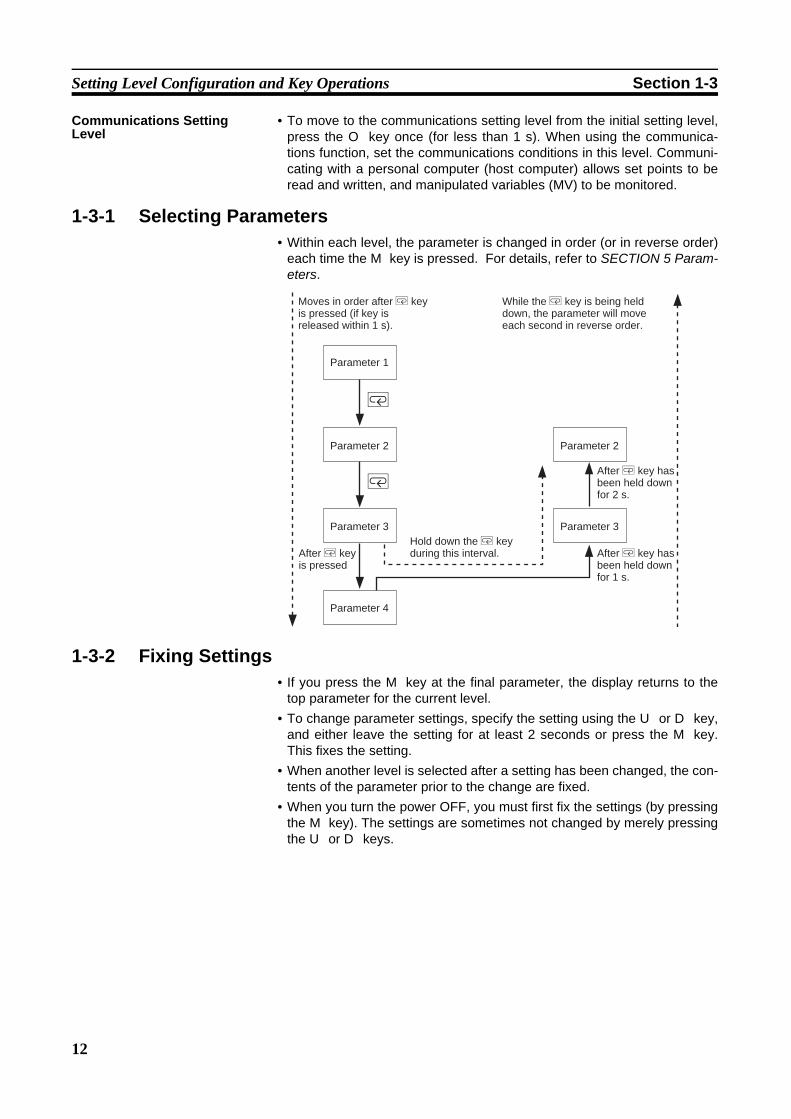
1-3-1 Selecting Parameters• Within each level, the parameter is changed in order (or in reverse order)
each time the M key is pressed. For details, refer to SECTION 5 Param-eters.
1-3-2 Fixing Settings• If you press the M key at the final parameter, the display returns to the
top parameter for the current level.• To change parameter settings, specify the setting using the U or D key,
and either leave the setting for at least 2 seconds or press the M key.This fixes the setting.
• When another level is selected after a setting has been changed, the con-tents of the parameter prior to the change are fixed.
• When you turn the power OFF, you must first fix the settings (by pressingthe M key). The settings are sometimes not changed by merely pressingthe U or D keys.
M
M
Moves in order after M key is pressed (if key is released within 1 s).
Parameter 1
Parameter 2
Parameter 3
After M key is pressed
Parameter 4
Hold down the M key during this interval.
While the M key is being held down, the parameter will move each second in reverse order.
Parameter 2
Parameter 3
After M key has been held down for 2 s.
After M key has been held down for 1 s.
13
Communications Function Section 1-4
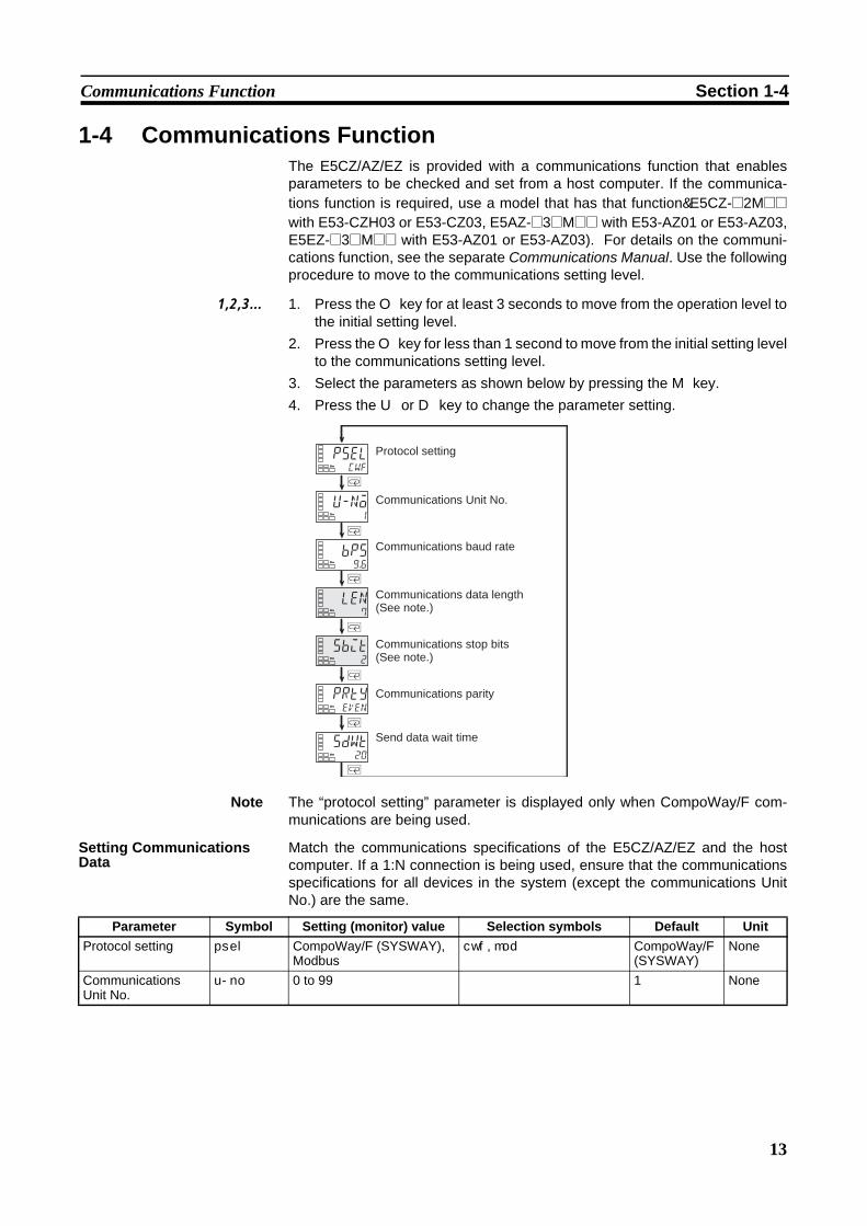
1-4 Communications FunctionThe E5CZ/AZ/EZ is provided with a communications function that enablesparameters to be checked and set from a host computer. If the communica-tions function is required, use a model that has that function(E5CZ-@2M@@with E53-CZH03 or E53-CZ03, E5AZ-@3@M@@ with E53-AZ01 or E53-AZ03,E5EZ-@3@M@@ with E53-AZ01 or E53-AZ03). For details on the communi-cations function, see the separate Communications Manual. Use the followingprocedure to move to the communications setting level.
1,2,3... 1. Press the O key for at least 3 seconds to move from the operation level tothe initial setting level.
2. Press the O key for less than 1 second to move from the initial setting levelto the communications setting level.
3. Select the parameters as shown below by pressing the M key.4. Press the U or D key to change the parameter setting.
Note The “protocol setting” parameter is displayed only when CompoWay/F com-munications are being used.
Setting Communications Data
Match the communications specifications of the E5CZ/AZ/EZ and the hostcomputer. If a 1:N connection is being used, ensure that the communicationsspecifications for all devices in the system (except the communications UnitNo.) are the same.
M
M
M
M
M
M
M
pselcwf
u-no1
bps9.6
len7
sbit2
prtyeven
sdwt20
Protocol setting
Communications Unit No.
Communications baud rate
Communications parity
Send data wait time
Communications data length (See note.)
Communications stop bits (See note.)
Parameter Symbol Setting (monitor) value Selection symbols Default UnitProtocol setting psel CompoWay/F (SYSWAY),
Modbuscwf, mod CompoWay/F
(SYSWAY)None
Communications Unit No.
u-no 0 to 99 1 None
14
Communications Function Section 1-4
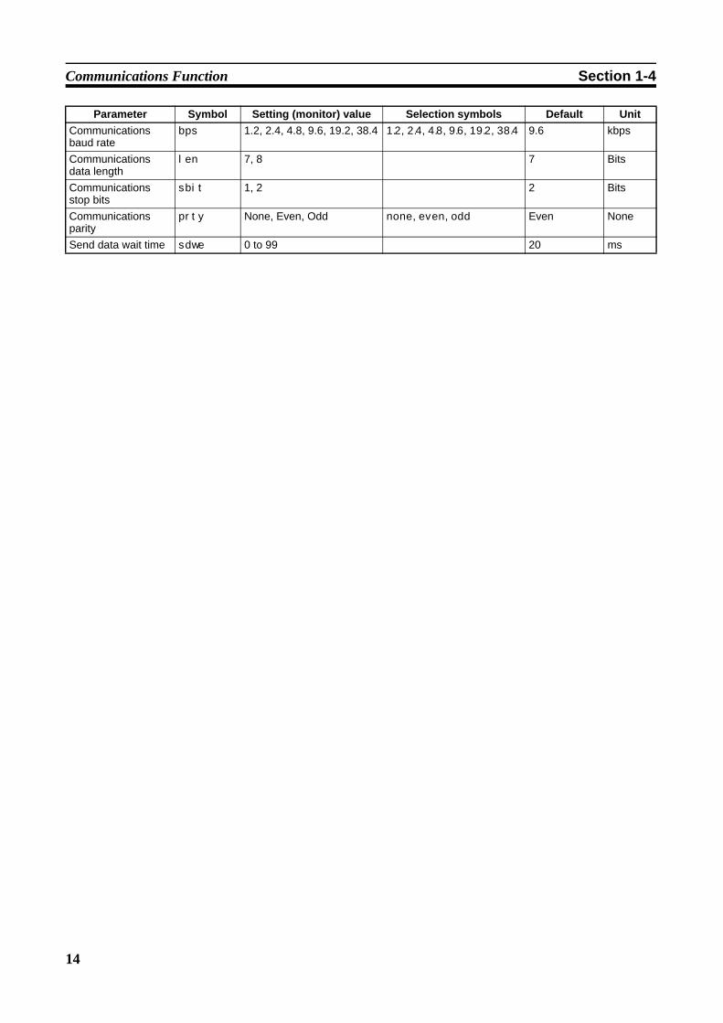
Communications baud rate
bps 1.2, 2.4, 4.8, 9.6, 19.2, 38.4 1.2, 2.4, 4.8, 9.6, 19.2, 38.4 9.6 kbps
Communications data length
len 7, 8 7 Bits
Communications stop bits
sbit 1, 2 2 Bits
Communications parity
prty None, Even, Odd none, even, odd Even None
Send data wait time sdwe 0 to 99 20 ms
Parameter Symbol Setting (monitor) value Selection symbols Default Unit
15
SECTION 2Preparations
This section describes the work required to prepare the E5CZ and E5CZ-U Digital Temperature Controllers for operation,including installation and wiring.
2-1 Installation. . . . . . . . . . . . . . . . . . . . . . . . . . . . . . . . . . . . . . . . . . . . . . . . . . . . 16
2-1-1 Dimensions . . . . . . . . . . . . . . . . . . . . . . . . . . . . . . . . . . . . . . . . . . . . 16
2-1-2 Panel Cutout . . . . . . . . . . . . . . . . . . . . . . . . . . . . . . . . . . . . . . . . . . . 17
2-1-3 Mounting. . . . . . . . . . . . . . . . . . . . . . . . . . . . . . . . . . . . . . . . . . . . . . 18
2-1-4 Removing the Temperature Controller from the Case . . . . . . . . . . . 20
2-2 Wiring Terminals . . . . . . . . . . . . . . . . . . . . . . . . . . . . . . . . . . . . . . . . . . . . . . 21
2-2-1 Terminal Arrangement . . . . . . . . . . . . . . . . . . . . . . . . . . . . . . . . . . . 21
2-2-2 Precautions when Wiring . . . . . . . . . . . . . . . . . . . . . . . . . . . . . . . . . 22
2-2-3 Wiring . . . . . . . . . . . . . . . . . . . . . . . . . . . . . . . . . . . . . . . . . . . . . . . . 22
2-3 Using the Support Software Port . . . . . . . . . . . . . . . . . . . . . . . . . . . . . . . . . . 27
16
Installation Section 2-1
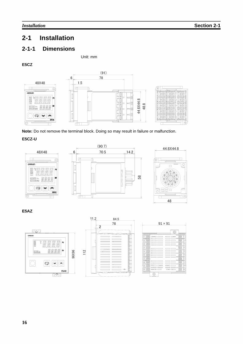
2-1 Installation2-1-1 Dimensions
Unit: mm
E5CZ
Note: Do not remove the terminal block. Doing so may result in failure or malfunction.
E5CZ-U
E5AZ
91 × 91
17
Installation Section 2-1
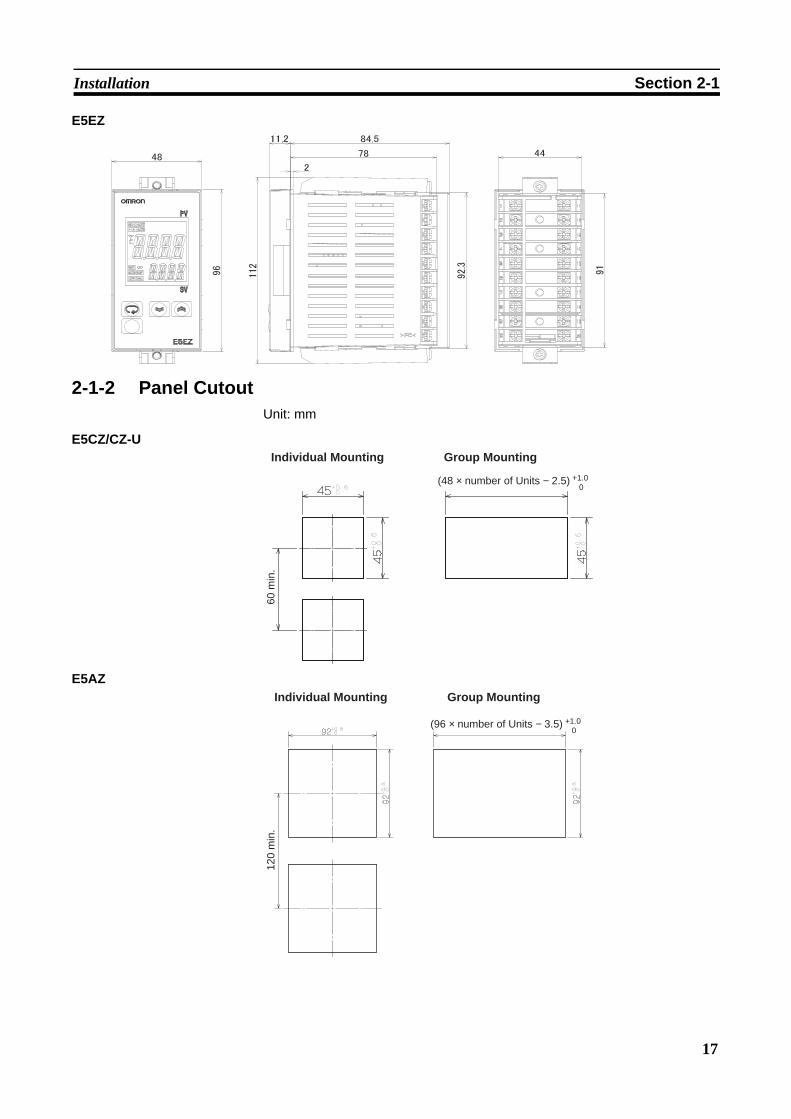
E5EZ
2-1-2 Panel CutoutUnit: mm
E5CZ/CZ-U
E5AZ
60 m
in.
+1.0 0
Individual Mounting Group Mounting
(48 × number of Units − 2.5)
120
min
.
+1.0 0
Individual Mounting Group Mounting
(96 × number of Units − 3.5)
18
Installation Section 2-1
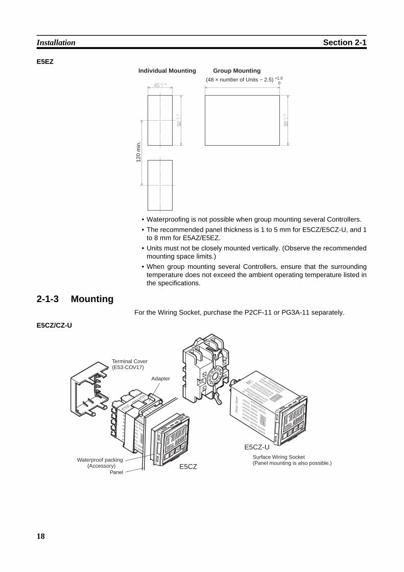
E5EZ
• Waterproofing is not possible when group mounting several Controllers.• The recommended panel thickness is 1 to 5 mm for E5CZ/E5CZ-U, and 1
to 8 mm for E5AZ/E5EZ.• Units must not be closely mounted vertically. (Observe the recommended
mounting space limits.)• When group mounting several Controllers, ensure that the surrounding
temperature does not exceed the ambient operating temperature listed inthe specifications.
2-1-3 MountingFor the Wiring Socket, purchase the P2CF-11 or PG3A-11 separately.
E5CZ/CZ-U
120
min
.
+1.0 0
Individual Mounting Group Mounting(48 × number of Units − 2.5)
E5CZ
E5CZ-U
Adapter
Waterproof packing (Accessory)
Panel
Surface Wiring Socket (Panel mounting is also possible.)
Terminal Cover (E53-COV17)

19
Installation Section 2-1
Mounting to the Panel
1,2,3... 1. For waterproof mounting, waterproof packing must be installed on theController. Waterproofing is not possible when group mounting severalControllers. Waterproof packing is not necessary when there is no need forthe waterproofing function. There is no waterproof packing included withthe E5CZ-U.
2. Insert the E5CZ/E5CZ-U into the mounting hole in the panel.3. Push the adapter from the terminals up to the panel, and temporarily fasten
the E5CZ/E5CZ-U.4. Tighten the two fastening screws on the adapter. Alternately tighten the
two screws little by little to maintain a balance. Tighten the screws to atorque of 0.29 to 0.39 N·m.
Mounting the Terminal CoverFor the E5CZ, make sure that the “UP” mark is facing up, and then fit the ter-minal cover into the holes on the top and bottom.
E5AZ/EZ
Mounting to the Panel
1,2,3... 1. For waterproof mounting, waterproof packing must be installed on theController. Waterproofing is not possible when group mounting severalControllers. Waterproof packing is not necessary when there is no need forthe waterproofing function.
2. Insert the E5AZ/E5EZ into the square mounting hole in the panel (thick-ness: 1 to 8 mm). Attach the Mounting Brackets provided with the productto the mounting grooves on the top and bottom surfaces of the rear case.
3. Use a ratchet to alternately tighten the screws on the top and bottomMounting Brackets little by little to maintain balance, until the ratchet turnsfreely.
Mounting the Terminal CoverFit the E53-COV11 Terminal Cover over the upper hook. Mount it in the direc-tion shown in the above diagram. If the terminal cover is mounted in the oppo-site direction, proper mounting of the fixtures may not be possible.
E5AZ
Waterproof packing(Accessory)
Panel
Terminal Cover (E53-COV11)
Mounting Bracket
E5EZ
Terminal Cover (E53-COV11)
Waterproof packing(Accessory)
Mounting Bracket
Panel

20
Installation Section 2-1
2-1-4 Removing the Temperature Controller from the CaseThe Temperature Controller can be removed from the case to perform main-tenance without removing the terminal leads. This is possible for only theE5CZ, E5AZ, and E5EZ, and not for the E5CZ-U. Check the specifications ofthe case and Temperature Controller before removing the Temperature Con-troller from the case.
E5CZ/AZ/EZ
1,2,3... 1. Insert a flat-blade screwdriver into the two tool insertion holes (one on thetop and one on the bottom) to release the hooks.
2. Insert the flat-blade screwdriver in the gap between the front panel andrear case, and pull out the front panel slightly. Hold the top and bottom ofthe front panel and carefully pull it out toward you, without applying unnec-essary force.
3. When inserting the E5CZ/AZ/EZ, check to make sure that the sealing rub-ber is in place and push the E5CZ/AZ/EZ toward the rear case until itsnaps into position. While pushing the E5CZ/AZ/EZ into place, push downon the hooks on the top and bottom surfaces of the rear case so that thehooks are securely locked in place. Be sure that electronic components donot come into contact with the case.
E5AZ E5EZ
(2)
(3)
(1)
(1)
(2)
(3)
(1)
(1)
E5CZ CZ-U
(2)
(3)
(1)
(1)
20 m
in.
0.4
2.0
Flat-blade screwdriver(Unit: mm)
21
Wiring Terminals Section 2-2
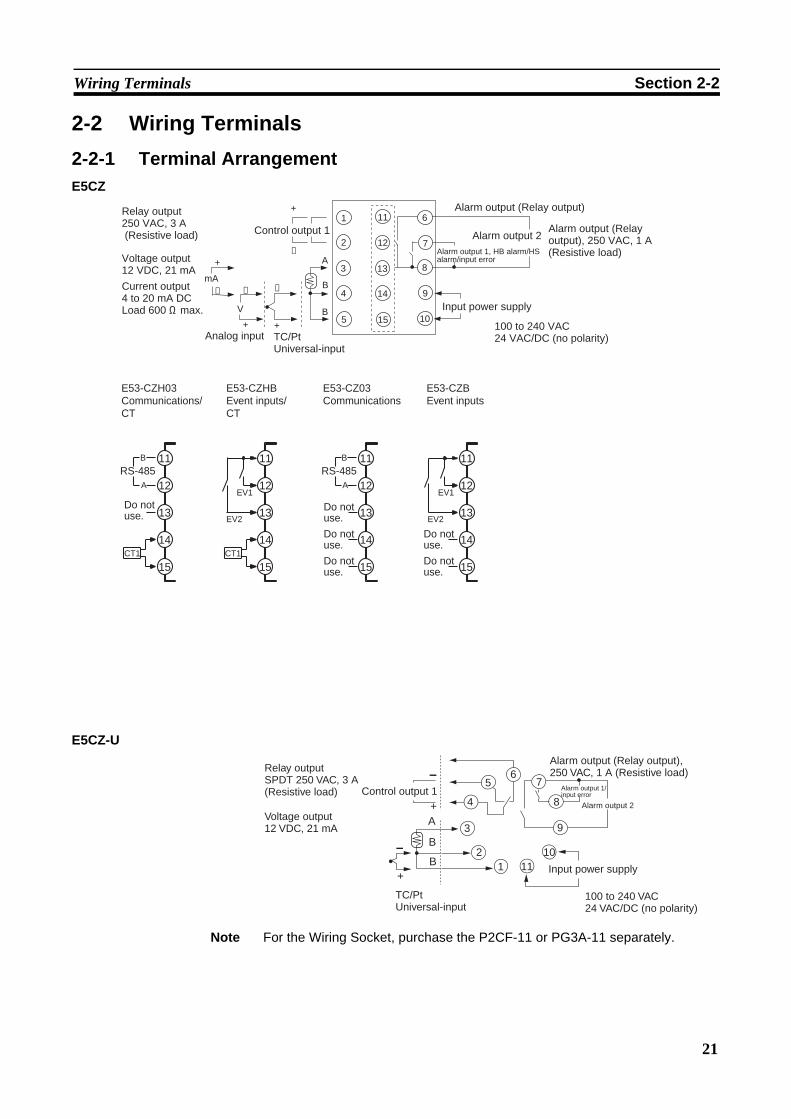
2-2 Wiring Terminals2-2-1 Terminal ArrangementE5CZ
E5CZ-U
Note For the Wiring Socket, purchase the P2CF-11 or PG3A-11 separately.
15
14
12
13
11
5
4
A
B
B
V
+
+
−
−
6
8
9
10
2
3
1
7
+
−
Relay output250 VAC, 3 A(Resistive load)
Voltage output12 VDC, 21 mA
Current output4 to 20 mA DCLoad 600 Ω max.
Analog input TC/PtUniversal-input
Control output 1
Alarm output (Relay output)
Alarm output 2
Input power supply
100 to 240 VAC24 VAC/DC (no polarity)
Alarm output 1, HB alarm/HS alarm/input error
Alarm output (Relay output), 250 VAC, 1 A (Resistive load)
mA
+
−
E53-CZ03Communications
Do notuse.
Do notuse.
Do notuse.
Do notuse.
Do notuse.
B
A
RS-48512
11
15
14
13
E53-CZBEvent inputs
EV1
EV2
12
11
15
14
13
E53-CZHBEvent inputs/CT
CT1
13
14
15
11
12
EV2
EV1
E53-CZH03Communications/CT
CT1
13
14
15
11
12
B
A
RS-485
Do notuse.
3
21
7
8
9
1011
5
4
6
A
B
B
+
Relay outputSPDT 250 VAC, 3 A(Resistive load)
Voltage output12 VDC, 21 mA
Control output 1
TC/PtUniversal-input
+Input power supply
Alarm output 2
100 to 240 VAC 24 VAC/DC (no polarity)
Alarm output (Relay output), 250 VAC, 1 A (Resistive load)
Alarm output 1/ input error
22
Wiring Terminals Section 2-2
E5AZ/EZ
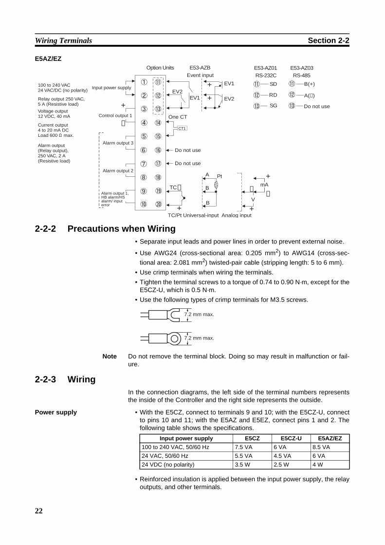
2-2-2 Precautions when Wiring• Separate input leads and power lines in order to prevent external noise.
• Use AWG24 (cross-sectional area: 0.205 mm2) to AWG14 (cross-sec-tional area: 2.081 mm2) twisted-pair cable (stripping length: 5 to 6 mm).
• Use crimp terminals when wiring the terminals.• Tighten the terminal screws to a torque of 0.74 to 0.90 N·m, except for the
E5CZ-U, which is 0.5 N·m.• Use the following types of crimp terminals for M3.5 screws.
Note Do not remove the terminal block. Doing so may result in malfunction or fail-ure.
2-2-3 WiringIn the connection diagrams, the left side of the terminal numbers representsthe inside of the Controller and the right side represents the outside.
Power supply • With the E5CZ, connect to terminals 9 and 10; with the E5CZ-U, connectto pins 10 and 11; with the E5AZ and E5EZ, connect pins 1 and 2. Thefollowing table shows the specifications.
• Reinforced insulation is applied between the input power supply, the relayoutputs, and other terminals.
−
+
CT1
EV1EV2
+
+ EV1
EV2
−
+
SD
RD
SG
B(+)
A(−)
RS-232C
E53-AZBOption Units
RS-485E53-AZ01 E53-AZ03
+
−
A
B
B
+
V
mA
Pt
TC−
100 to 240 VAC24 VAC/DC (no polarity)
Relay output 250 VAC, 5 A (Resistive load)
Voltage output12 VDC, 40 mA
Current output4 to 20 mA DCLoad 600 Ω max.
Alarm output (Relay output), 250 VAC, 2 A (Resistive load)
Input power supply
Control output 1
Alarm output 2
Alarm output 3
Alarm output 1, HB alarm/HS alarm/ input error
Event input
TC/Pt Universal-input Analog input
One CT
Do not use
Do not use
Do not use
7.2 mm max.
7.2 mm max.
Input power supply E5CZ E5CZ-U E5AZ/EZ100 to 240 VAC, 50/60 Hz 7.5 VA 6 VA 8.5 VA24 VAC, 50/60 Hz 5.5 VA 4.5 VA 6 VA24 VDC (no polarity) 3.5 W 2.5 W 4 W

23
Wiring Terminals Section 2-2
Input • Make the connections as shown below, using terminals 3 to 5 for theE5CZ, pins 1 to 3 for the E5CZ-U, and pins 18 to 20 for the E5AZ/EZ, andmatching the input types.
Control Output 1 • Outputs are sent from terminals 1 and 2 with the E5CZ, from pins 4 to 6with the E5CZ-U, and from pins 3 and 4 with the E5AZ/EZ. The followingdiagrams show the available outputs and their internal equalizing circuits.
• The following table shows the specifications for each output type.
E5CZ/CZ-U
E5CZ E5CZ-U
+
−
5
4
3
5
4
3
5
4
3
+
−
1
2
3
1
2
3
ThermocouplePlatinum resistance thermometer Analog input Thermocouple
Platinum resistance thermometer
+
+
−V
mA−
−
+
+
−mA
V
+
−
E5AZ/EZ
ThermocouplePlatinum resistance thermometer Analog input
18
19
20 20 20
19 19
18 18
A
B
B
A
B
B
A
B
B
Output type SpecificationsRelay 250 VAC, 3 A (resistive load), electrical durability: 100,000
operationsVoltage (PNP) PNP type, 12 VDC ±15%, 21 mA (with short-circuit protec-
tion)Current(Not for E5CZ-U)
DC 4 to 20 mA, resistive load: 600 Ω max.Resolution: Approx. 2,700
E5CZ E5CZ-U
1
2
1
2
L
+
− 6
5
4 4
6
5
+
−GND
GND
L
+V+V
+−
−
1
2
+
+V
L
Relay Voltage Current Relay Voltage
+v
L
+
−
L
+v
+
−
E5AZ/EZ
Relay Voltage Current
GND

24
Wiring Terminals Section 2-2
E5AZ/EZ
• A voltage output (control output) is not electrically isolated from the inter-nal circuits. When using a grounding thermocouple, do not connect any ofthe control output terminals to the ground. If control output terminals areconnected to the ground, errors will occur in the measured temperaturevalues as a result of leakage current.
• Control output 1 (Voltage output) is not isolated.
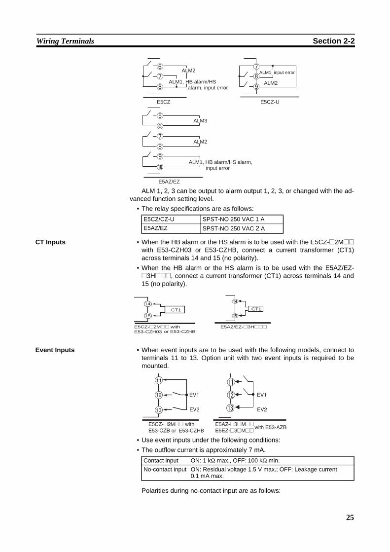
Alarm Outputs 1, 2, and 3 • On the E5CZ-@2M@@, alarm output 1 (ALM1) is output across terminals7 and 8, and alarm output 2 (ALM2) is output across terminals 6 and 8.
• On the E5CZ-@2T@U, alarm output 1 (ALM1) is output across terminals 7and 8, and alarm output 2 (ALM2) is output across terminals 7 and 9.
• On the E5AZ/EZ-@3@@@@, alarm output 1 (ALM1) is output across ter-minals 9 and 10, alarm output 2 (ALM2) is output across terminals 7 and8, and alarm output 3 (ALM3) is output across terminals 5 and 6.
• When the “input error output” parameter is set to ON, alarm output 1 turnsON when an input error occurs.
• When the HB alarm or the HS alarm is used with the E5CZ-@2M@@ withE53-CZH03 or E53-CZHB alarms are output across terminals 7 and 8.
• When the HB alarm or the HS alarm is used with the E5AZ-@3H@@@orthe E5EZ-@3H@@@, alarms are output across terminals 9 and 10.
• On the E5CZ and E5CZ-U, when heating/cooling control is used, alarmoutput 2 becomes control output (cooling).
• On the E5AZ and E5EZ, when heating/cooling control is used, alarm out-put 3 becomes control output (cooling).
• For models that have a heater burnout alarm, an OR of alarm output 1and the HB alarm/HS alarm is output. If ALM1 is to be used for HB alarmonly, set the alarm 1 type to 0 and do not use alarm output 1.
• The following diagrams show the internal equalizing circuits for alarm out-puts 1, 2, and 3.
Output type SpecificationsRelay 250 VAC, 5 A (resistive load), electrical durability: 100,000
operationsVoltage (PNP) PNP type, 12 VDC +15%/−20%, 40 mA (with short-circuit
protection)Current DC 4 to 20 mA, resistive load: 600 Ω max.
Resolution: Approx. 2,700
25
Wiring Terminals Section 2-2
ALM 1, 2, 3 can be output to alarm output 1, 2, 3, or changed with the ad-vanced function setting level.
• The relay specifications are as follows:
CT Inputs • When the HB alarm or the HS alarm is to be used with the E5CZ-@2M@@with E53-CZH03 or E53-CZHB, connect a current transformer (CT1)across terminals 14 and 15 (no polarity).
• When the HB alarm or the HS alarm is to be used with the E5AZ/EZ-@3H@@@, connect a current transformer (CT1) across terminals 14 and15 (no polarity).
Event Inputs • When event inputs are to be used with the following models, connect toterminals 11 to 13. Option unit with two event inputs is required to bemounted.
• Use event inputs under the following conditions:• The outflow current is approximately 7 mA.
Polarities during no-contact input are as follows:
E5CZ/CZ-U SPST-NO 250 VAC 1 AE5AZ/EZ SPST-NO 250 VAC 2 A
E5CZ E5CZ-U
ALM2
ALM1, HB alarm/HS alarm, input error
ALM1, input error
ALM2
ALM3
ALM2
ALM1, HB alarm/HS alarm, input error
E5AZ/EZ
E5CZ-@2M@@ withE53-CZH03
15
14
CT1 CT1
E5AZ/EZ-@3H@@@or E53-CZHB
Contact input ON: 1 kΩ max., OFF: 100 kΩ min.No-contact input ON: Residual voltage 1.5 V max.; OFF: Leakage current
0.1 mA max.
or E53-CZHBM M
M
26
Wiring Terminals Section 2-2
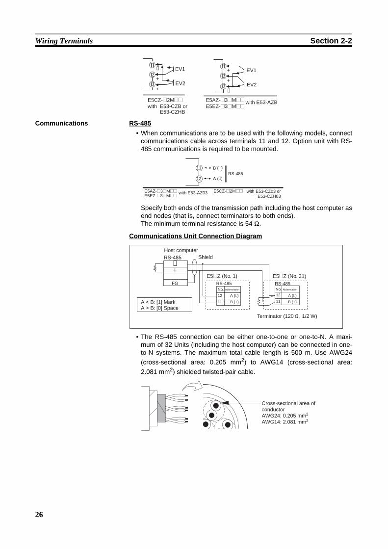
Communications RS-485• When communications are to be used with the following models, connect
communications cable across terminals 11 and 12. Option unit with RS-485 communications is required to be mounted.
Specify both ends of the transmission path including the host computer asend nodes (that is, connect terminators to both ends).The minimum terminal resistance is 54 Ω.
Communications Unit Connection Diagram
• The RS-485 connection can be either one-to-one or one-to-N. A maxi-mum of 32 Units (including the host computer) can be connected in one-to-N systems. The maximum total cable length is 500 m. Use AWG24(cross-sectional area: 0.205 mm2) to AWG14 (cross-sectional area:2.081 mm2) shielded twisted-pair cable.
EV1
EV2+
−
+EV1
EV2
E5CZ-@2M@@with E53-CZB or
E5AZ-@3@M@@E5EZ-@3@M@@
+
−
+
with E53-AZB
E53-CZHB
E5AZ-@3@M@@
11
12RS-485
A (−)
B (+)
E5EZ-@3@M@@ with E53-AZ03 E5CZ-@2M@@ with E53-CZ03 orE53-CZH03
No.
12
11
A (−)
B (+)
A (−)
B (+)
RS-485
−+
FGNo.
12
11
RS-485
E5@Z (No. 1) E5@Z (No. 31)
RS-485Host computer
Shield
Terminator (120 Ω, 1/2 W)
Abbreviation Abbreviation
A < B: [1] MarkA > B: [0] Space
Cross-sectional area of conductorAWG24: 0.205 mm2
AWG14: 2.081 mm2
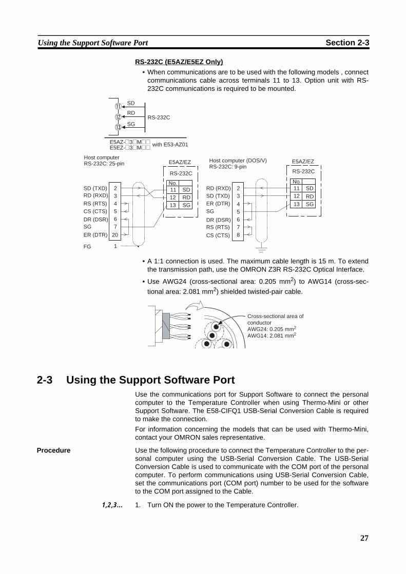
27
Using the Support Software Port Section 2-3
RS-232C (E5AZ/E5EZ Only)• When communications are to be used with the following models , connect
communications cable across terminals 11 to 13. Option unit with RS-232C communications is required to be mounted.
• A 1:1 connection is used. The maximum cable length is 15 m. To extendthe transmission path, use the OMRON Z3R RS-232C Optical Interface.
• Use AWG24 (cross-sectional area: 0.205 mm2) to AWG14 (cross-sec-tional area: 2.081 mm2) shielded twisted-pair cable.
2-3 Using the Support Software PortUse the communications port for Support Software to connect the personalcomputer to the Temperature Controller when using Thermo-Mini or otherSupport Software. The E58-CIFQ1 USB-Serial Conversion Cable is requiredto make the connection.For information concerning the models that can be used with Thermo-Mini,contact your OMRON sales representative.
Procedure Use the following procedure to connect the Temperature Controller to the per-sonal computer using the USB-Serial Conversion Cable. The USB-SerialConversion Cable is used to communicate with the COM port of the personalcomputer. To perform communications using USB-Serial Conversion Cable,set the communications port (COM port) number to be used for the softwareto the COM port assigned to the Cable.
1,2,3... 1. Turn ON the power to the Temperature Controller.
SD
RD
SGRS-232C
RD (RXD)SD (TXD)ER (DTR)SG
DR (DSR)RS (RTS)
CS (CTS)
3
4567
2
8
11No.
12
13
SD
RDSG
1FG
SD (TXD)RD (RXD)
RS (RTS)CS (CTS)
DR (DSR)SG
ER (DTR)
34567
20
2 11No.
1213
SDRDSG
E5AZ-@3@M@@
Host computer RS-232C: 25-pin E5AZ/EZ
RS-232C
Host computer (DOS/V) RS-232C: 9-pin
E5AZ/EZ
RS-232C
E5EZ-@3@M@@ with E53-AZ01
Cross-sectional area of conductorAWG24: 0.205 mm2
AWG14: 2.081 mm2
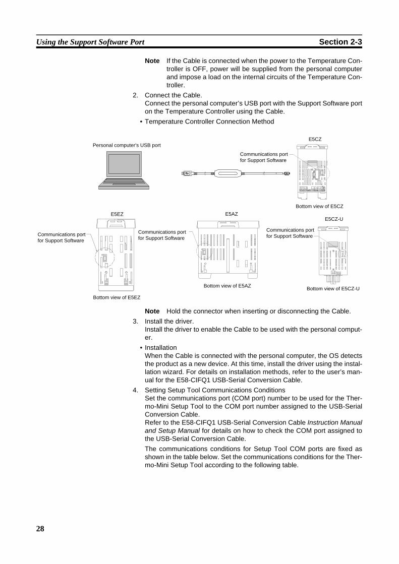
28
Using the Support Software Port Section 2-3
Note If the Cable is connected when the power to the Temperature Con-troller is OFF, power will be supplied from the personal computerand impose a load on the internal circuits of the Temperature Con-troller.
2. Connect the Cable.Connect the personal computer’s USB port with the Support Software porton the Temperature Controller using the Cable.
• Temperature Controller Connection Method
Note Hold the connector when inserting or disconnecting the Cable.3. Install the driver.
Install the driver to enable the Cable to be used with the personal comput-er.
• InstallationWhen the Cable is connected with the personal computer, the OS detectsthe product as a new device. At this time, install the driver using the instal-lation wizard. For details on installation methods, refer to the user’s man-ual for the E58-CIFQ1 USB-Serial Conversion Cable.
4. Setting Setup Tool Communications ConditionsSet the communications port (COM port) number to be used for the Ther-mo-Mini Setup Tool to the COM port number assigned to the USB-SerialConversion Cable.Refer to the E58-CIFQ1 USB-Serial Conversion Cable Instruction Manualand Setup Manual for details on how to check the COM port assigned tothe USB-Serial Conversion Cable. The communications conditions for Setup Tool COM ports are fixed asshown in the table below. Set the communications conditions for the Ther-mo-Mini Setup Tool according to the following table.
E5CZ
E5AZE5EZ
Personal computer's USB port
Communications port for Support Software
Communications port for Support Software
Communications port for Support Software
Bottom view of E5EZ
Bottom view of E5CZ
Bottom view of E5AZ
Communications port for Support Software
E5CZ-U
Bottom view of E5CZ-U
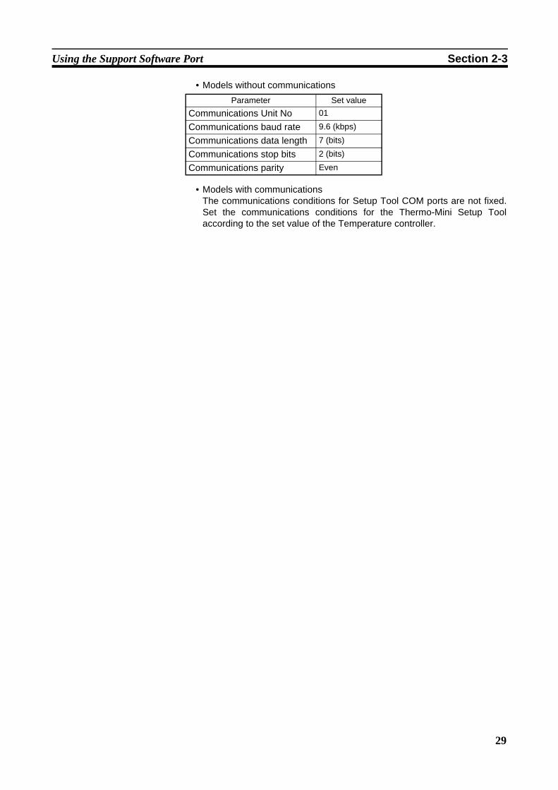
29
Using the Support Software Port Section 2-3
• Models without communications
• Models with communicationsThe communications conditions for Setup Tool COM ports are not fixed.Set the communications conditions for the Thermo-Mini Setup Toolaccording to the set value of the Temperature controller.
Parameter Set value
Communications Unit No 01
Communications baud rate 9.6 (kbps)
Communications data length 7 (bits)
Communications stop bits 2 (bits)
Communications parity Even

30
Using the Support Software Port Section 2-3
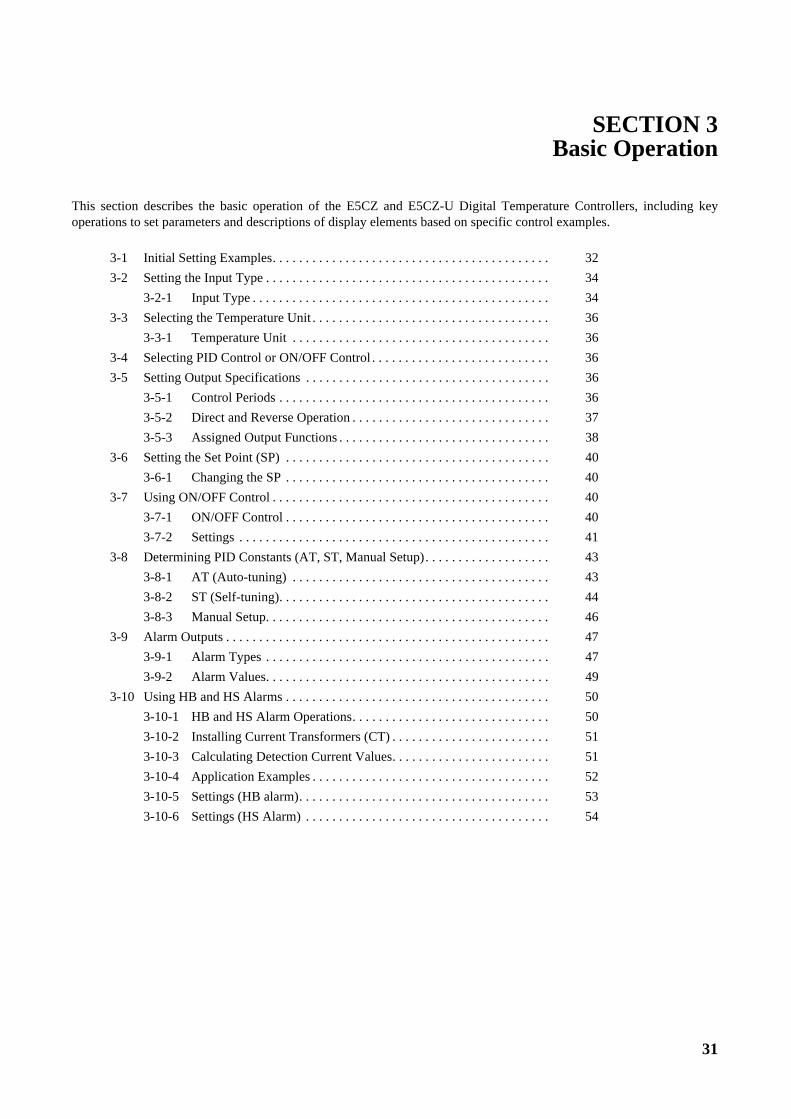
31
Section
SECTION 3Basic Operation
This section describes the basic operation of the E5CZ and E5CZ-U Digital Temperature Controllers, including keyoperations to set parameters and descriptions of display elements based on specific control examples.
3-1 Initial Setting Examples. . . . . . . . . . . . . . . . . . . . . . . . . . . . . . . . . . . . . . . . . . 32
3-2 Setting the Input Type . . . . . . . . . . . . . . . . . . . . . . . . . . . . . . . . . . . . . . . . . . . 34
3-2-1 Input Type . . . . . . . . . . . . . . . . . . . . . . . . . . . . . . . . . . . . . . . . . . . . . 34
3-3 Selecting the Temperature Unit . . . . . . . . . . . . . . . . . . . . . . . . . . . . . . . . . . . . 36
3-3-1 Temperature Unit . . . . . . . . . . . . . . . . . . . . . . . . . . . . . . . . . . . . . . . 36
3-4 Selecting PID Control or ON/OFF Control . . . . . . . . . . . . . . . . . . . . . . . . . . . 36
3-5 Setting Output Specifications . . . . . . . . . . . . . . . . . . . . . . . . . . . . . . . . . . . . . 36
3-5-1 Control Periods . . . . . . . . . . . . . . . . . . . . . . . . . . . . . . . . . . . . . . . . . 36
3-5-2 Direct and Reverse Operation . . . . . . . . . . . . . . . . . . . . . . . . . . . . . . 37
3-5-3 Assigned Output Functions . . . . . . . . . . . . . . . . . . . . . . . . . . . . . . . . 38
3-6 Setting the Set Point (SP) . . . . . . . . . . . . . . . . . . . . . . . . . . . . . . . . . . . . . . . . 40
3-6-1 Changing the SP . . . . . . . . . . . . . . . . . . . . . . . . . . . . . . . . . . . . . . . . 40
3-7 Using ON/OFF Control . . . . . . . . . . . . . . . . . . . . . . . . . . . . . . . . . . . . . . . . . . 40
3-7-1 ON/OFF Control . . . . . . . . . . . . . . . . . . . . . . . . . . . . . . . . . . . . . . . . 40
3-7-2 Settings . . . . . . . . . . . . . . . . . . . . . . . . . . . . . . . . . . . . . . . . . . . . . . . 41
3-8 Determining PID Constants (AT, ST, Manual Setup). . . . . . . . . . . . . . . . . . . 43
3-8-1 AT (Auto-tuning) . . . . . . . . . . . . . . . . . . . . . . . . . . . . . . . . . . . . . . . 43
3-8-2 ST (Self-tuning). . . . . . . . . . . . . . . . . . . . . . . . . . . . . . . . . . . . . . . . . 44
3-8-3 Manual Setup. . . . . . . . . . . . . . . . . . . . . . . . . . . . . . . . . . . . . . . . . . . 46
3-9 Alarm Outputs . . . . . . . . . . . . . . . . . . . . . . . . . . . . . . . . . . . . . . . . . . . . . . . . . 47
3-9-1 Alarm Types . . . . . . . . . . . . . . . . . . . . . . . . . . . . . . . . . . . . . . . . . . . 47
3-9-2 Alarm Values. . . . . . . . . . . . . . . . . . . . . . . . . . . . . . . . . . . . . . . . . . . 49
3-10 Using HB and HS Alarms . . . . . . . . . . . . . . . . . . . . . . . . . . . . . . . . . . . . . . . . 50
3-10-1 HB and HS Alarm Operations. . . . . . . . . . . . . . . . . . . . . . . . . . . . . . 50
3-10-2 Installing Current Transformers (CT) . . . . . . . . . . . . . . . . . . . . . . . . 51
3-10-3 Calculating Detection Current Values. . . . . . . . . . . . . . . . . . . . . . . . 51
3-10-4 Application Examples . . . . . . . . . . . . . . . . . . . . . . . . . . . . . . . . . . . . 52
3-10-5 Settings (HB alarm). . . . . . . . . . . . . . . . . . . . . . . . . . . . . . . . . . . . . . 53
3-10-6 Settings (HS Alarm) . . . . . . . . . . . . . . . . . . . . . . . . . . . . . . . . . . . . . 54
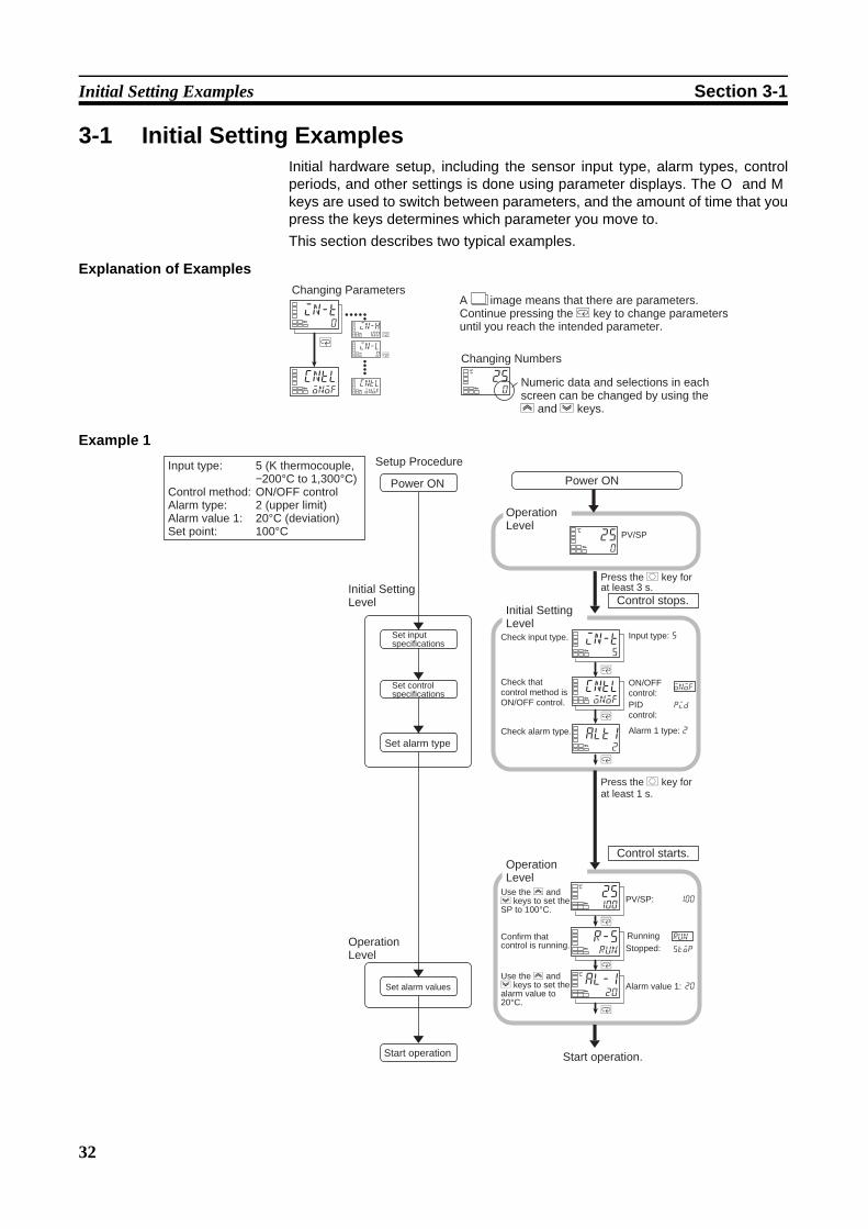
32
Initial Setting Examples Section 3-1
3-1 Initial Setting ExamplesInitial hardware setup, including the sensor input type, alarm types, controlperiods, and other settings is done using parameter displays. The O and Mkeys are used to switch between parameters, and the amount of time that youpress the keys determines which parameter you move to.This section describes two typical examples.
Explanation of Examples
Example 1
250
C
in-t0
cntlonof
cntl
M
M
M
onof
in-l0
in-h100
Changing ParametersA image means that there are parameters. Continue pressing the M key to change parameters until you reach the intended parameter.
Changing Numbers
Numeric data and selections in each screen can be changed by using the U and D keys.
100
20
onof
pid
run
stop
250
C
in-t5
cntlonof
alt12
25100
C
r-srun
al-120
C
M
M
M
M
M
M
Input type: 5 (K thermocouple, −200°C to 1,300°C)
Control method: ON/OFF controlAlarm type: 2 (upper limit)Alarm value 1: 20°C (deviation)Set point: 100°C
Setup Procedure
Power ON
Initial Setting Level
Set input specifications
Set control specifications
Set alarm type
Operation Level
Set alarm values
Start operation
Power ON
Operation Level
PV/SP
Press the O key for at least 3 s.
Control stops.Initial Setting Level
Input type: 5
Check that control method is ON/OFF control.
ON/OFF control:PID control:
Check alarm type.
Check input type.
Alarm 1 type: 2
Press the O key for at least 1 s.
Control starts.Operation Level
Use the U and D keys to set the SP to 100°C.
PV/SP:
Confirm that control is running.
RunningStopped:
Use the U and D keys to set the alarm value to 20°C.
Alarm value 1:
Start operation.
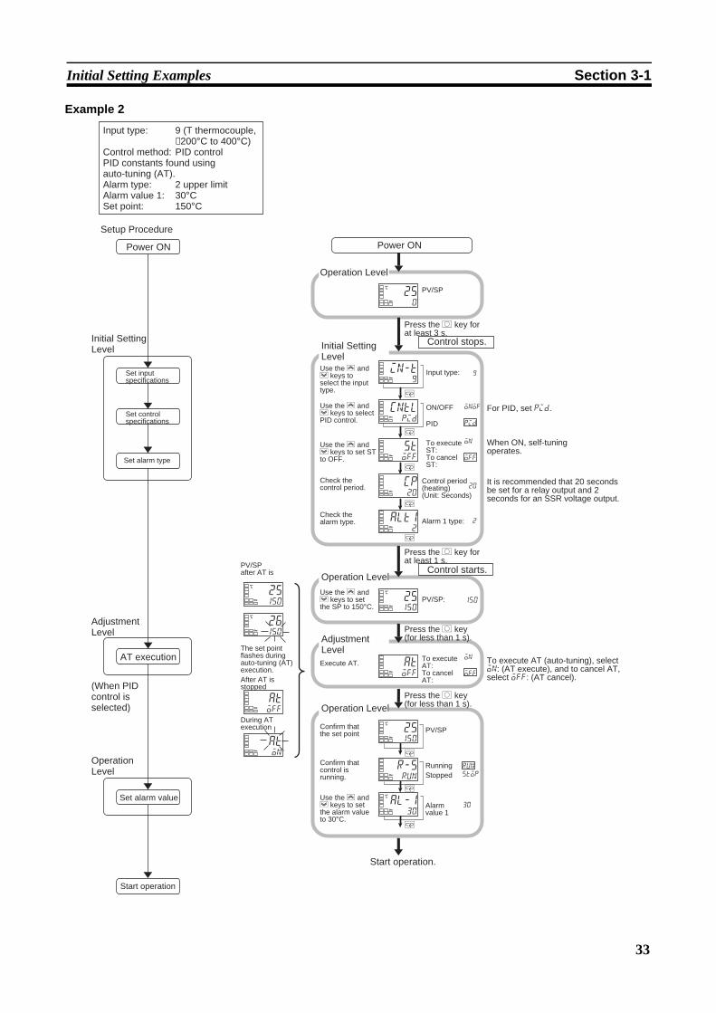
33
Initial Setting Examples Section 3-1
Example 2
9
20
30
2
150
onof
pid
on
off
on
off
run
stop
Input type: 9 (T thermocouple, −200°C to 400°C)
Control method: PID controlPID constants found using auto-tuning (AT).Alarm type: 2 upper limitAlarm value 1: 30°C Set point: 150°C
Setup Procedure
Power ON
Initial Setting Level
Set input specifications
Set control specifications
Set alarm type
Adjustment Level
AT execution
(When PID control is selected)
Operation Level
Set alarm value
Start operation
Power ON
250
C
in-t9
cntlpid
stoff
cp20
alt12
25150
C
atoff
25150
C
r-srun
al-130
C
aton
atoff
26150
C
25150
C
M
M
M
M
M
M
M
M
Operation Level
PV/SP
Press the O key for at least 3 s.
Control stops.Initial Setting LevelUse the U and D keys to select the input type.
Input type:
Use the U and D keys to select PID control.
ON/OFF
Use the U and D keys to set ST to OFF.
To execute ST:
PID
To cancel ST:
Check the control period.
Control period (heating)(Unit: Seconds)
Check the alarm type. Alarm 1 type:
For PID, set pid.
When ON, self-tuning operates.
It is recommended that 20 seconds be set for a relay output and 2 seconds for an SSR voltage output.
Press the O key for at least 1 s.
Operation Level
Use the U and D keys to set the SP to 150°C.
PV/SP:
Adjustment LevelExecute AT.
To execute AT:To cancel AT:
To execute AT (auto-tuning), select on: (AT execute), and to cancel AT, select off: (AT cancel).
Press the O key (for less than 1 s).
Press the O key (for less than 1 s).
Control starts.
Operation Level
Confirm that the set point PV/SP
Confirm that control is running.
RunningStopped
Use the U and D keys to set the alarm value to 30°C.
Alarm value 1
Start operation.
PV/SPafter AT is
The set point flashes during auto-tuning (AT) execution.After AT is stopped
During AT execution
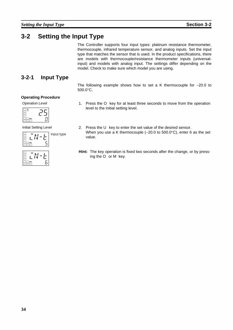
34
Setting the Input Type Section 3-2
3-2 Setting the Input TypeThe Controller supports four input types: platinum resistance thermometer,thermocouple, infrared temperature sensor, and analog inputs. Set the inputtype that matches the sensor that is used. In the product specifications, thereare models with thermocouple/resistance thermometer inputs (universal-input) and models with analog input. The settings differ depending on themodel. Check to make sure which model you are using.
3-2-1 Input TypeThe following example shows how to set a K thermocouple for −20.0 to500.0°C.
Operating ProcedureOperation Level 1. Press the O key for at least three seconds to move from the operation
level to the initial setting level.
Initial Setting Level 2. Press the U key to enter the set value of the desired sensor.When you use a K thermocouple (−20.0 to 500.0°C), enter 6 as the setvalue.
Hint: The key operation is fixed two seconds after the change, or by press-ing the O or M key.
C
250
in-t5
Input type
in-t6

35
Setting the Input Type Section 3-2
List of Input Types
• The default is 5.• If a platinum resistance thermometer is mistakenly connected while a set-
ting for other than a platinum resistance thermometer is in effect, S.ERRwill be displayed. To clear the S.ERR display, check the wiring and thenturn the power OFF and back ON.
• The default is 0.
Input type Specifications Set value Input temperature setting rangeControllers with Ther-mocouple/Resistance Thermome-ter Univer-sal-input
Platinum resistance thermometer
Pt100 0 −200 to 850 (°C)/−300 to 1,500 (°F)1 −199.9 to 500.0 (°C)/−199.9 to 900.0 (°F)2 0.0 to 100.0 (°C)/0.0 to 210.0 (°F)
JPt100 3 −199.9 to 500.0 (°C)/−199.9 to 900.0 (°F)4 0.0 to 100.0 (°C)/0.0 to 210.0 (°F)
Thermocouple K 5 −200 to 1,300 (°C)/−300 to 2,300 (°F)6 −20.0 to 500.0 (°C)/0.0 to 900.0 (°F)
J 7 −100 to 850 (°C)/−100 to 1,500 (°F)8 −20.0 to 400.0 (°C)/0.0 to 750.0 (°F)
T 9 −200 to 400 (°C)/−300 to 700 (°F)10 −199.9 to 400.0 (°C)/−199.9 to 700.0 (°F)
E 11 0 to 600 (°C)/0 to 1,100 (°F)L 12 −100 to 850 (°C)/−100 to 1,500 (°F)U 13 −200 to 400 (°C)/−300 to 700 (°F)
14 −199.9 to 400.0 (°C)/−199.9 to 700.0 (°F)N 15 −200 to 1,300 (°C)/−300 to 2,300 (°F)R 16 0 to 1,700 (°C)/0 to 3,000 (°F)S 17 0 to 1,700 (°C)/0 to 3,000 (°F)B 18 100 to 1,800 (°C)/300 to 3,200 (°F)
Infrared temperature sensor ES1B
10 to 70°C 19 0 to 90 (°C)/0 to 190 (°F)60 to 120°C 20 0 to 120 (°C)/0 to 240 (°F)115 to 165°C 21 0 to 165 (°C)/0 to 320 (°F)140 to 260°C 22 0 to 260 (°C)/0 to 500 (°F)
Analog input 0 to 50 mV 23 Either of the following ranges, by scaling:−1,999 to 9,999−199.9 to 999.9
Input type Specifications Set value Input temperature setting rangeModels with analog input
Current input 4 to 20 mA 0 Either of the following ranges, by scaling:−1,999 to 9,999−199.9 to 999.9−19.99 to 99.99−1.999 to 9.999
0 to 20 mA 1Voltage input 1 to 5 V 2
0 to 5 V 30 to 10 V 4

36
Selecting the Temperature Unit Section 3-3
3-3 Selecting the Temperature Unit3-3-1 Temperature Unit
• Either °C or °F can be selected as the temperature unit.• Set the temperature unit in the “temperature unit” parameter of the initial
setting level. The default is c (°C).
Operating Procedure The following example shows how to select °C as the temperature unit.
3-4 Selecting PID Control or ON/OFF ControlTwo control methods are supported: 2-PID control and ON/OFF control.Switching between 2-PID control and ON/OFF control is executed by meansof the “PID ON/OFF” parameter in the initial setting level. When this parame-ter is set to pid, 2-PID control is selected, and when set to onof, ON/OFFcontrol, is selected. The default is onof.
2-PID Control PID control is set by AT (auto-tuning), ST (self-tuning), or manual setting.For PID control, set the PID constants in the “proportional band” (P), “integraltime” (I), and “derivative time” (D) parameters.
ON/OFF Control In ON/OFF control, the control output is turned ON when the process value islower than the current set point, and the control output is turned OFF whenthe process value is higher than the current set point (reverse operation).
3-5 Setting Output Specifications3-5-1 Control Periods
• Set the output periods (control periods). Though a shorter period providesbetter control performance, it is recommended that the control period beset to 20 seconds or longer for a relay output to preserve the service lifeof the relay. After the settings have been made in the initial setup, read-just the control period, as required, by means such as trial operation.
• Set the control periods in the “control period (heating)” and “control period(cooling)” parameters in the initial setting level. The default is 20 seconds.
• The “control period (cooling)” parameter is used only for heating/coolingcontrol.
• When control output 1 is used as a current output, “control period (heat-ing)” cannot be used.
Operation Level 1. Press the O key for at least three seconds to move from the operationlevel to the initial setting level.
Initial Setting Level 2. Select the “temperature unit” parameter by pressing the M key.Press the U or D key to select either °C or °F.c: °Cf: °F
3. To return to the operation level, press the O key for at least one second.
C
300
in-t5
Input type
d-uc
Temperature unit
cp
c-cp
Control period (heating)
Control period (cooling)

37
Setting Output Specifications Section 3-5
3-5-2 Direct and Reverse Operation• “Direct operation” increases the manipulated variable whenever the pro-
cess value increases. “Reverse operation” decreases the manipulatedvariable whenever the process value increases.
For example, when the process value (PV) is lower than the set point (SP)in a heating control system, the manipulated variable increases accordingto the difference between the PV and SP. Accordingly, reverse operationis used in a heating control system. Direct operation is used in a coolingcontrol system, in which the operation is the opposite of a heating controlsystem.
• Direct/reverse operation is set in the “direct/reverse operation” parameterin the initial setting level. The default is or-r (reverse operation).
Operating Procedure In this example, the input type, temperature unit, direct/reverse operation, andcontrol period (heating) parameters are checked.
Input type = s (K thermocouple)Temperature unit = c (°C)Direct/reverse operation = or-r (reverse operation)Control period (heating) = 20 (seconds)
orev
100%
0%
100%
0%
Manipulated variable Manipulated variable
Low temperature
Set Value High temperature
Low temperature
Set Value High temperature
Direct operation Reverse operation
Operation Level 1. Press the O key for at least three seconds to move from the operationlevel to the initial setting level.
Initial Setting Level 2. The input type is displayed. When the input type is being set for the firsttime, s (K thermocouple) is set. To select a different sensor, press the Uor D key.
3. Select the “temperature unit” parameter by pressing the M key. The de-fault is c (°C). To select f (°F), press the U key.
4. Select the “control period (heating)” parameter by pressing the M key.The default is 20.
C
300
in-t5
Input type
d-uc
Temperature unit
cp20
Control period (heating)

38
Setting Output Specifications Section 3-5
3-5-3 Assigned Output Functions• Function assignments can be changed by changing the settings for con-
trol and alarm assignments.• The default function assignments for each output are shown below.
• Each output is automatically initialized as shown below by changing thecontrol mode.
Example: E5CZ
Note For the E5AZ/EZ, alarm 3 is assigned for control output (cooling) (alarm output 2 is assigned for alarm 2).In this manual, assigned control outputs and alarm outputs are indicated asfollows: “Control output 1 must be assigned” or “Alarm 1 must be assigned.”
Operating Procedure The following example sets the following control and alarm assignments.Control output 1: Control output (heating); Alarm output 1: Alarm 1; Alarm out-put 2: Control output (cooling).
5. Select the “direct/reverse operation” parameter by pressing the M key.The default is or-r (reverse operation). To select or-d (direct opera-tion), press the U key.
Operation Level 6. To return to the operation level, press the O key for at least one second.
orevor-r
Direct/reverse operation
C
300
PV/SP
Parameter name Symbol Initial statusControl output 1 assignment out1 Control output (heating)Alarm output 1 assignment alm1 Alarm 1Alarm output 2 assignment alm2 Alarm 2Alarm output 3 assignment (E5AZ/EZ only)
alm3 Alarm 3
Parameter name Symbol Standard Heating/coolingControl output 1 assignment
out1 Control output (heating) Control output (heating)
Alarm output 1 assignment
alm1 Alarm 1 Alarm 1
Alarm output 2 assignment
alm2 Alarm 2 (See note.) Control output (cooling) (See note.)
Operation Level 1. Press the O key for at least 3 seconds to move from the operation levelto the initial setting level.
Initial Setting Levell
Initial Setting Level
2. Select the “standard or heating/cooling” parameter by pressing the Mkey.
C
25100
PV/SP
in-t5
Input type
5-hcstnd
Standard or heating/cooling

39
Setting Output Specifications Section 3-5
Initial Setting Level 3. Press the U key to set the parameter to h-c.
Note The following output assignments do not need to be set because theyare set automatically by changing the control mode, but they areshown here as a reference for checking the assignments for each out-put.
4. Select the “move to advanced function setting level” parameter by press-ing the M key.
Advanced Function Setting Level 5. Press the D key to enter the password (“−169”), and move from the initialsetting level to the advanced function setting level.
Advanced Function Setting Level 6. Select the “alarm output 1 assignment” parameter by pressing the Mkey.
7. Press the U or D key to set o.(The default is o.)
Advanced Function Setting Level 8. Select the “alarm output 1 assignment” parameter by pressing the Mkey.
9. Press the U or D key to set alm1.(The default is alm1.)
Advanced Function Setting LevelE5CZ
E5AZ/EZ
10. Select the “alarm output 2 assignment” parameter by pressing the Mkey.(The default of the E5CZ is c-o.)
(The default of the E5AZ/EZ is alm2.)
11. Press the U or D key to set c-o.
Initial Setting Level 12. Press the O key for at least one second to move from the advanced func-tion setting level to the initial setting level.
5-hch-c
amov0
Move to ad-vanced function setting level
initoff
Parameter initialization
out1o
Control output 1 assignment
out1o
alm1alm1
Alarm output 1 assignment
alm1alm1
alm2c-o
Alarm output 2 assignment
alm2alm2
alm2c-o
in-t5
Input type
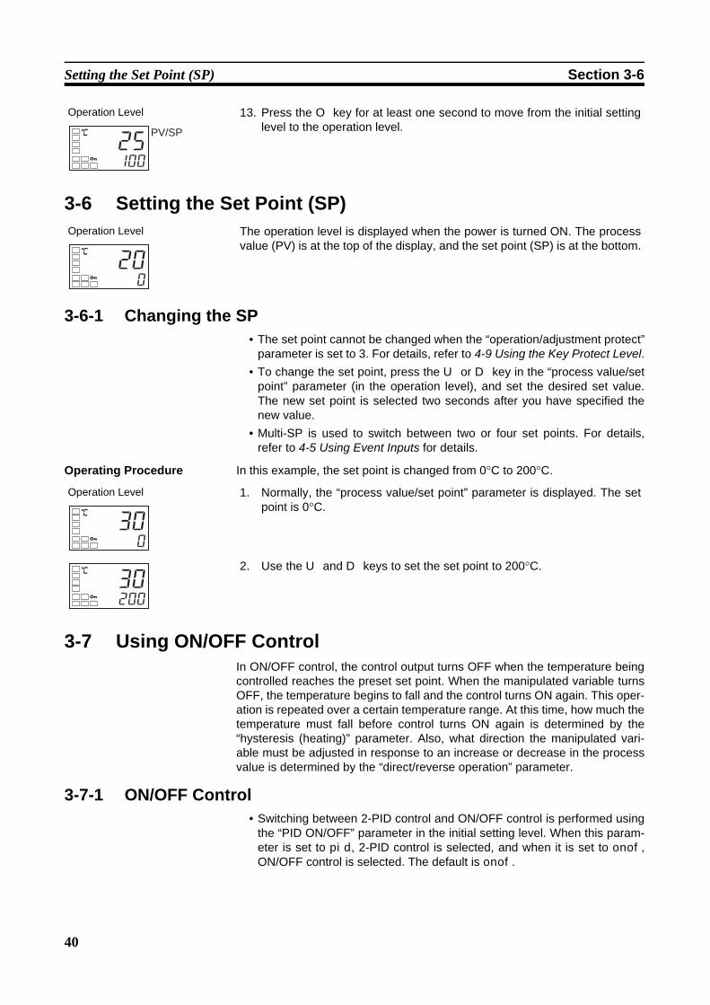
40
Setting the Set Point (SP) Section 3-6
3-6 Setting the Set Point (SP)
3-6-1 Changing the SP• The set point cannot be changed when the “operation/adjustment protect”
parameter is set to 3. For details, refer to 4-9 Using the Key Protect Level.• To change the set point, press the U or D key in the “process value/set
point” parameter (in the operation level), and set the desired set value.The new set point is selected two seconds after you have specified thenew value.
• Multi-SP is used to switch between two or four set points. For details,refer to 4-5 Using Event Inputs for details.
Operating Procedure In this example, the set point is changed from 0°C to 200°C.
3-7 Using ON/OFF ControlIn ON/OFF control, the control output turns OFF when the temperature beingcontrolled reaches the preset set point. When the manipulated variable turnsOFF, the temperature begins to fall and the control turns ON again. This oper-ation is repeated over a certain temperature range. At this time, how much thetemperature must fall before control turns ON again is determined by the“hysteresis (heating)” parameter. Also, what direction the manipulated vari-able must be adjusted in response to an increase or decrease in the processvalue is determined by the “direct/reverse operation” parameter.
3-7-1 ON/OFF Control• Switching between 2-PID control and ON/OFF control is performed using
the “PID ON/OFF” parameter in the initial setting level. When this param-eter is set to pid, 2-PID control is selected, and when it is set to onof,ON/OFF control is selected. The default is onof.
Operation Level 13. Press the O key for at least one second to move from the initial settinglevel to the operation level.
Operation Level The operation level is displayed when the power is turned ON. The processvalue (PV) is at the top of the display, and the set point (SP) is at the bottom.
C
25100
PV/SP
C
200
Operation Level 1. Normally, the “process value/set point” parameter is displayed. The setpoint is 0°C.
2. Use the U and D keys to set the set point to 200°C.
C
300
C
30200

41
Using ON/OFF Control Section 3-7
Hysteresis • With ON/OFF control, hysteresis is used to stabilize operation whenswitching between ON and OFF. The control output (heating) and controloutput (cooling) functions are set in the “hysteresis (heating)” and “hyster-esis (cooling)” parameters, respectively.
• In standard control (heating or cooling control), the setting of the “hystere-sis (heating)” parameter in the adjustment level is used as the hysteresisregardless of whether the control type is heating control or cooling con-trol.
Three-position Control
• In heating/cooling control, a dead band (an area where both control out-puts are 0) can be set to either the heating or cooling side. This makes itpossible to use 3-position control.
Parameters
3-7-2 SettingsTo execute ON/OFF control, set the “set point,” “PID ON/OFF,” and “hystere-sis” parameters.
Setting the “PID ON/OFF” ParameterOperating Procedure Confirm that the “PID ON/OFF” parameter is set to onof in the initial setting
level.
PV
ON
OFF
Reverse operation
Hysteresis (heating)
Set point
Symbol Parameter: Level Applications-hc
cntl
orev
c-db
c-sc
hys
chys
Standard or heating/cooling: Initial setting levelPID ON/OFF: Initial setting levelDirect/reverse operation: Initial setting levelDead band: Adjustment levelCooling coefficient: Adjustment levelHysteresis (heating): Adjustment levelHysteresis (cooling): Adjustment level
Specifying control methodSpecifying control methodSpecifying control methodHeating/cooling controlHeating/cooling controlON/OFF controlON/OFF control
PV
ON
OFF
Reverse operation
Dead band
Hysteresis (heating) Hysteresis (cooling)
Heating side
Cooling side
Set point
Operation Level 1. Press the O key for at least three seconds to move from the operationlevel to the initial setting level.
C
25100
PV
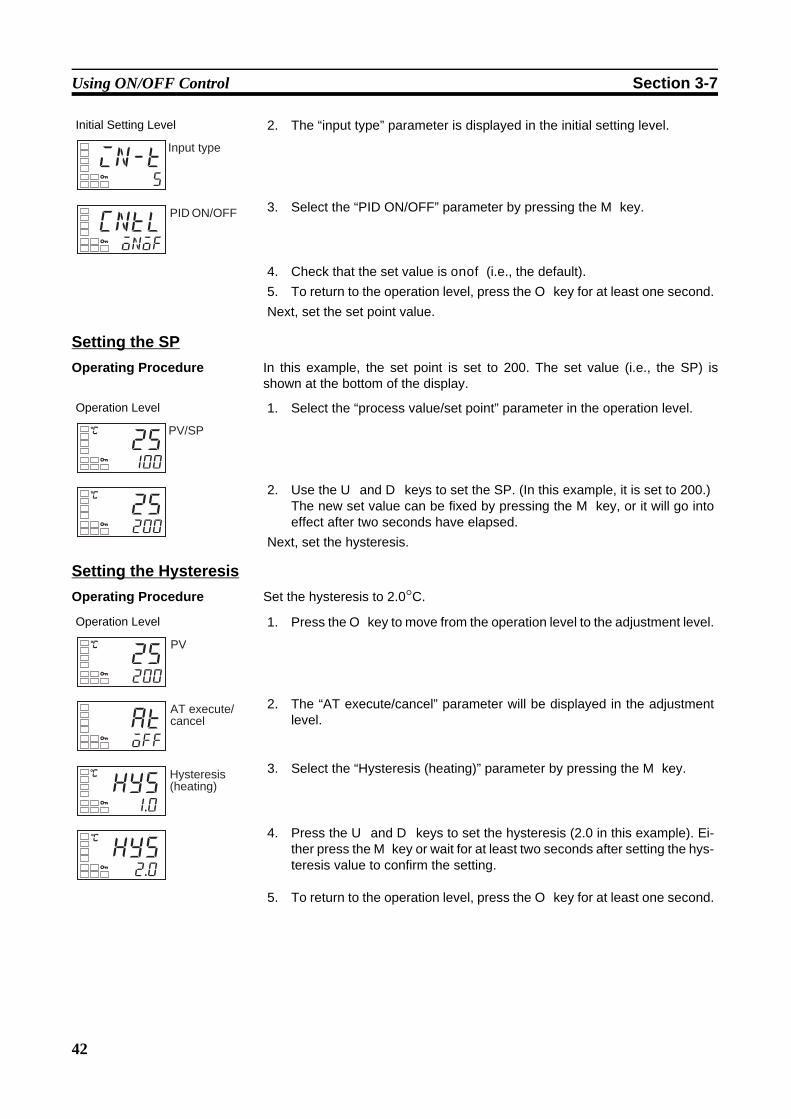
42
Using ON/OFF Control Section 3-7
Setting the SPOperating Procedure In this example, the set point is set to 200. The set value (i.e., the SP) is
shown at the bottom of the display.
Setting the HysteresisOperating Procedure Set the hysteresis to 2.0°C.
Initial Setting Level 2. The “input type” parameter is displayed in the initial setting level.
3. Select the “PID ON/OFF” parameter by pressing the M key.
4. Check that the set value is onof (i.e., the default).5. To return to the operation level, press the O key for at least one second.Next, set the set point value.
in-t5
Input type
cntlonof
PID ON/OFF
Operation Level 1. Select the “process value/set point” parameter in the operation level.
2. Use the U and D keys to set the SP. (In this example, it is set to 200.)The new set value can be fixed by pressing the M key, or it will go intoeffect after two seconds have elapsed.
Next, set the hysteresis.
C
25100
PV/SP
C
25200
Operation Level 1. Press the O key to move from the operation level to the adjustment level.
2. The “AT execute/cancel” parameter will be displayed in the adjustmentlevel.
3. Select the “Hysteresis (heating)” parameter by pressing the M key.
4. Press the U and D keys to set the hysteresis (2.0 in this example). Ei-ther press the M key or wait for at least two seconds after setting the hys-teresis value to confirm the setting.
5. To return to the operation level, press the O key for at least one second.
C
25200
PV
atoff
AT execute/ cancel
hys1.0
Hysteresis (heating)
C
hys2.0
C
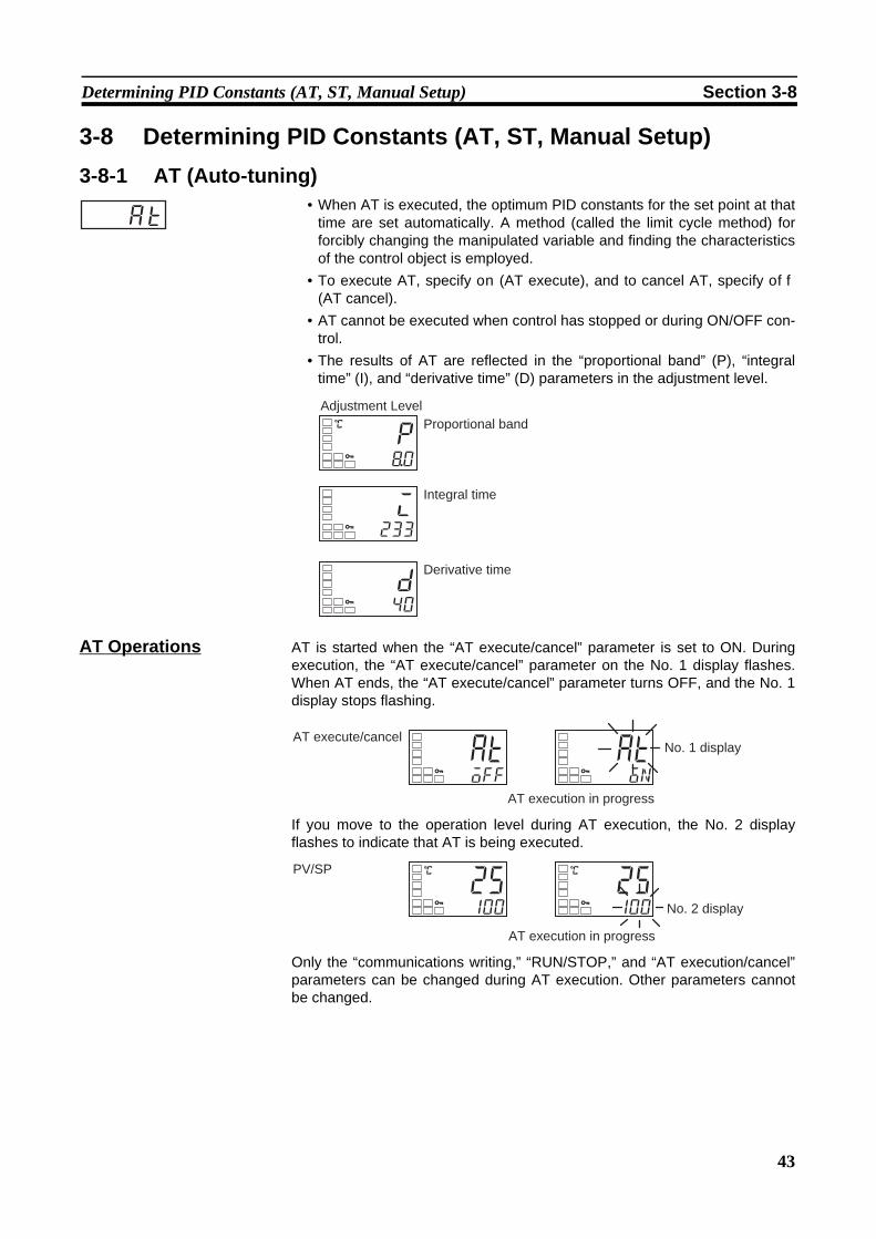
43
Determining PID Constants (AT, ST, Manual Setup) Section 3-8
3-8 Determining PID Constants (AT, ST, Manual Setup)3-8-1 AT (Auto-tuning)
• When AT is executed, the optimum PID constants for the set point at thattime are set automatically. A method (called the limit cycle method) forforcibly changing the manipulated variable and finding the characteristicsof the control object is employed.
• To execute AT, specify on (AT execute), and to cancel AT, specify off
(AT cancel).• AT cannot be executed when control has stopped or during ON/OFF con-
trol.• The results of AT are reflected in the “proportional band” (P), “integral
time” (I), and “derivative time” (D) parameters in the adjustment level.
AT Operations AT is started when the “AT execute/cancel” parameter is set to ON. Duringexecution, the “AT execute/cancel” parameter on the No. 1 display flashes.When AT ends, the “AT execute/cancel” parameter turns OFF, and the No. 1display stops flashing.
If you move to the operation level during AT execution, the No. 2 displayflashes to indicate that AT is being executed.
Only the “communications writing,” “RUN/STOP,” and “AT execution/cancel”parameters can be changed during AT execution. Other parameters cannotbe changed.
at
i233
C
p(0
d40
Adjustment LevelProportional band
Integral time
Derivative time
atoff
aton
AT execute/cancelNo. 1 display
AT execution in progress
C
25100
C
25100
PV/SP
AT execution in progress
No. 2 display

44
Determining PID Constants (AT, ST, Manual Setup) Section 3-8
Operating Procedure This procedure executes auto-tuning (AT).
3-8-2 ST (Self-tuning)ST (auto-tuning) is a function that finds PID constants by using step responsetuning (SRT) when Controller operation begins or when the set point ischanged.Once the PID constants have been calculated, ST is not executed when thenext control operation is started as long as the set point remains unchanged.ST (self-tuning) is enabled when the “ST” parameter is set to ON in the initialsetting level.When the ST function is in operation, be sure to turn the power supply of theload connected to the control output ON simultaneously with or before startingController operation.When executing self-tuning, turn ON power for the load (e.g., heater) at thesame time as or before supplying power to the Digital Temperature Controller.If power is turned ON for the Digital Temperature Controller before turning ONpower for the load, self-tuning will not be performed properly and optimumcontrol will not be achieved.
Note PID ConstantsWhen control characteristics are already known, PID constants can be setdirectly to adjust control. PID constants are set in the “proportional band” (P),“integral time” (I), and “derivative time” (D) parameters in the adjustment level.
Operating Procedure This procedure executes self-tuning (ST).
Adjustment Level 1. Press the O key to move from the operation level to the adjustment level.
2. Press the U key to start execution of AT (auto-tuning).on will be displayed during AT execution.
3. off will be displayed when AT ends.
Operation Level 4. To return to the operation level, press the O key.
atoff
AT execute/ cancel
aton
atoff
C
250
PV
st
Initial Setting Level 1. Press the O key for at least three seconds to move from the operationlevel to the initial setting level.
2. Select the “ST” parameter by pressing the M key.3. Press the U key to select on. ON is the default.
in-t5
Input type
ston
ST
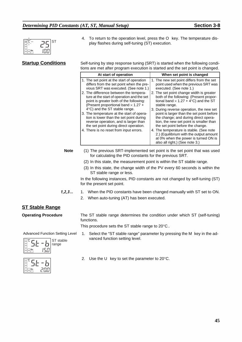
45
Determining PID Constants (AT, ST, Manual Setup) Section 3-8
Startup Conditions Self-tuning by step response tuning (SRT) is started when the following condi-tions are met after program execution is started and the set point is changed.
Note (1) The previous SRT-implemented set point is the set point that was usedfor calculating the PID constants for the previous SRT.
(2) In this state, the measurement point is within the ST stable range.(3) In this state, the change width of the PV every 60 seconds is within the
ST stable range or less.In the following instances, PID constants are not changed by self-tuning (ST)for the present set point.
1,2,3... 1. When the PID constants have been changed manually with ST set to ON.2. When auto-tuning (AT) has been executed.
ST Stable RangeOperating Procedure The ST stable range determines the condition under which ST (self-tuning)
functions.This procedure sets the ST stable range to 20°C..
4. To return to the operation level, press the O key. The temperature dis-play flashes during self-tuning (ST) execution.C
25100
ST
At start of operation When set point is changed1. The set point at the start of operation
differs from the set point when the pre-vious SRT was executed. (See note 1.)
2. The difference between the tempera-ture at the start of operation and the set point is greater both of the following: (Present proportional band × 1.27 + 4°C) and the ST stable range.
3. The temperature at the start of opera-tion is lower than the set point during reverse operation, and is larger than the set point during direct operation.
4. There is no reset from input errors.
1. The new set point differs from the set point used when the previous SRT was executed. (See note 1.)
2. The set point change width is greater both of the following: (Present propor-tional band × 1.27 + 4°C) and the ST stable range.
3. During reverse operation, the new set point is larger than the set point before the change; and during direct opera-tion, the new set point is smaller than the set point before the change.
4. The temperature is stable. (See note 2.) (Equilibrium with the output amount at 0% when the power is turned ON is also all right.) (See note 3.)
Advanced Function Setting Level 1. Select the “ST stable range” parameter by pressing the M key in the ad-vanced function setting level.
2. Use the U key to set the parameter to 20°C.
C
st-b1%0
ST stable range
C
st-b2*0
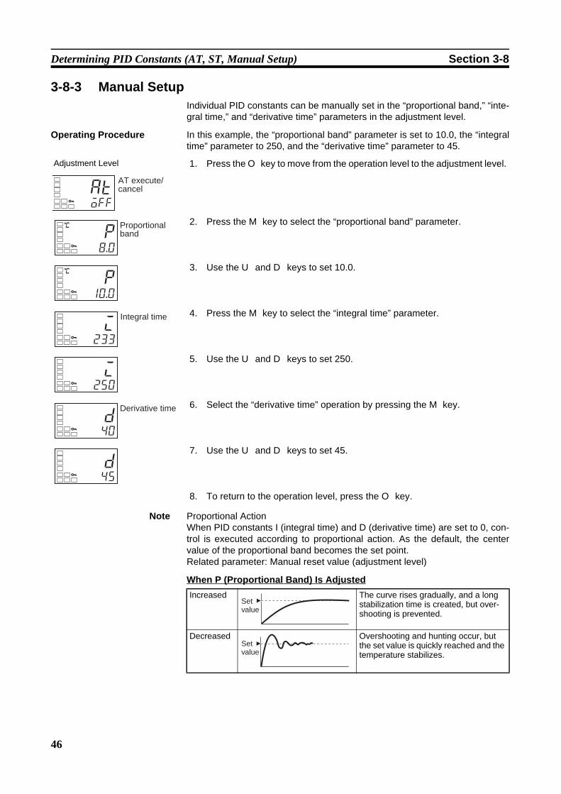
46
Determining PID Constants (AT, ST, Manual Setup) Section 3-8
3-8-3 Manual SetupIndividual PID constants can be manually set in the “proportional band,” “inte-gral time,” and “derivative time” parameters in the adjustment level.
Operating Procedure In this example, the “proportional band” parameter is set to 10.0, the “integraltime” parameter to 250, and the “derivative time” parameter to 45.
Note Proportional ActionWhen PID constants I (integral time) and D (derivative time) are set to 0, con-trol is executed according to proportional action. As the default, the centervalue of the proportional band becomes the set point.Related parameter: Manual reset value (adjustment level)
When P (Proportional Band) Is Adjusted
Adjustment Level 1. Press the O key to move from the operation level to the adjustment level.
2. Press the M key to select the “proportional band” parameter.
3. Use the U and D keys to set 10.0.
4. Press the M key to select the “integral time” parameter.
5. Use the U and D keys to set 250.
6. Select the “derivative time” operation by pressing the M key.
7. Use the U and D keys to set 45.
8. To return to the operation level, press the O key.
atoff
AT execute/ cancel
C
p8.0
Proportional band
C
p10.0
i233
Integral time
i250
d40
Derivative time
d45
Increased The curve rises gradually, and a long stabilization time is created, but over-shooting is prevented.
Decreased Overshooting and hunting occur, but the set value is quickly reached and the temperature stabilizes.
Set value
Set value

47
Alarm Outputs Section 3-9
When I (Integral Time) Is Adjusted
When D (Derivative Time) Is Adjusted
3-9 Alarm Outputs• Alarms can be used by the E5CZ-@2M@@ (2 alarm outputs), E5AZ/EZ-
@3@@@@ (3 alarm outputs), or the E5CZ-@2T@U (2 alarm outputs).Alarm outputs are determined by a combination of “alarm type,” “alarmvalue,” and “alarm hysteresis” alarm output conditions. For details, referto 4-2 Alarm Hysteresis.
• This section describes the “alarm type,” “alarm value,” “upper-limit alarm”and “lower-limit alarm” parameters.
3-9-1 Alarm Types
Increased It takes a long time to reach the set point.It takes time to achieve a stable state, but overshooting, undershooting, and hunting are reduced.
Decreased Overshooting and undershooting occur.Hunting occurs.The Controller starts up faster.
Increased Overshooting, undershooting, and sta-bilization times are reduced, but fine hunting occurs on changes in the curve itself.
Decreased Overshooting and undershooting increase, and it takes time to return to the set point.
Set value
Set value
Set value
Set value
Set value Alarm type Alarm output operationWhen alarm value
X is positiveWhen alarm value
X is negative0 Alarm function OFF Output OFF
1(See note1.)
Upper- and lower-limit See note 2.
2 Upper-limit
3 Lower-limit
4 (See note 1.)
Upper- and lower-limit range
See note 3.
5 (See note 1.)
Upper- and lower-limit with standby sequence
See note 4.
6 Upper-limit with standby sequence
7 Lower-limit with standby sequence
L HONOFF
SP
XONOFF
SP
ONOFF
SP
X
XONOFF
SP
XONOFF
SP
L HONOFF
SP
L HONOFF
SP
See note 5.
XONOFF
SP
ONOFF
SP
X
XONOFF
SP
XONOFF
SP
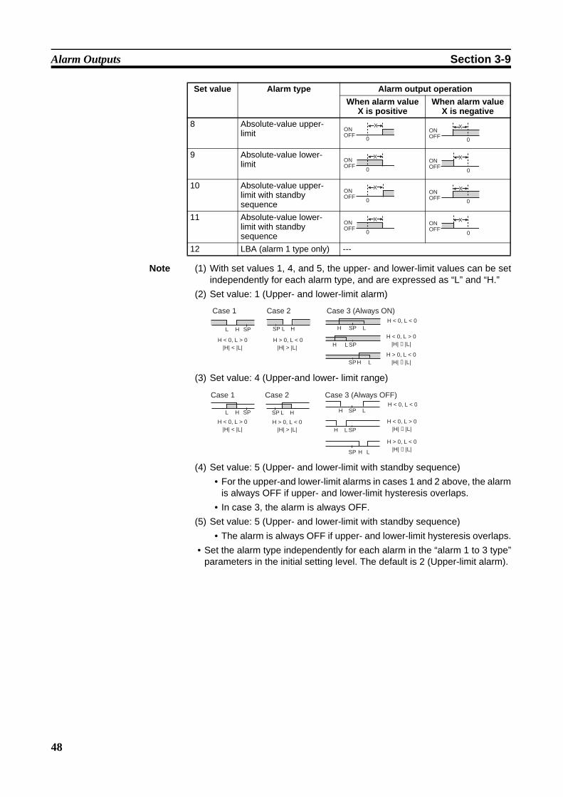
48
Alarm Outputs Section 3-9
Note (1) With set values 1, 4, and 5, the upper- and lower-limit values can be setindependently for each alarm type, and are expressed as “L” and “H.”
(2) Set value: 1 (Upper- and lower-limit alarm)
(3) Set value: 4 (Upper-and lower- limit range)
(4) Set value: 5 (Upper- and lower-limit with standby sequence)• For the upper-and lower-limit alarms in cases 1 and 2 above, the alarm
is always OFF if upper- and lower-limit hysteresis overlaps.• In case 3, the alarm is always OFF.
(5) Set value: 5 (Upper- and lower-limit with standby sequence)• The alarm is always OFF if upper- and lower-limit hysteresis overlaps.
• Set the alarm type independently for each alarm in the “alarm 1 to 3 type”parameters in the initial setting level. The default is 2 (Upper-limit alarm).
8 Absolute-value upper-limit
9 Absolute-value lower-limit
10 Absolute-value upper-limit with standby sequence
11 Absolute-value lower-limit with standby sequence
12 LBA (alarm 1 type only) ---
Set value Alarm type Alarm output operationWhen alarm value
X is positiveWhen alarm value
X is negativeX
ONOFF
0
XONOFF
0
ONOFF
X
0
ONOFF
X
0
XONOFF
0
XONOFF
0
ONOFF
X
0
ONOFF
X
0
L H
H < 0, L > 0|H| < |L|
SP L H
H > 0, L < 0|H| > |L|
SP LHH < 0, L < 0
SP
LHH < 0, L > 0
|H| ≥ |L|SP
LHH > 0, L < 0
|H| ≤ |L|SP
Case 1 Case 2 Case 3 (Always ON)
L H
H < 0, L > 0|H| < |L|
SP HL
H > 0, L < 0|H| > |L|
SP LHH < 0, L < 0
SP
L
L
H
H
H < 0, L > 0|H| ≥ |L|SP
SP
H > 0, L < 0|H| ≤ |L|
Case 1 Case 2 Case 3 (Always OFF)

49
Alarm Outputs Section 3-9
3-9-2 Alarm Values• Alarm values are indicated by “X” in the table on the previous page. When
the upper and lower limits are set independently, “H” is displayed forupper limit values, and “L” is displayed for lower limit values.
• To set the alarm value upper and lower limits for deviation, set the upperand lower limits in each of the “alarm 1 to 3 upper limit,” and “alarm 1 to 3lower limit” parameters in the operation level.
Operating Procedure This procedure sets alarm 1 as an upper-limit alarm. The related parametersand settings are shown below. The alarm is output when the set pointexceeds 10°C. (In this example, the temperature unit is °C.)Alarm 1 type = 2 (Upper-limit alarm)Alarm value 1= 10
al1l
al1h
al2l
al2h
al-1
al-2
al3l
al3h
al-3
Alarm lower limit value
Alarm upper limit value
Alarm value
Initial Setting Level 1. Press the O key for at least three seconds to move from the operationlevel to the initial setting level.
2. Select the “alarm 1 type” parameter by pressing the M key. Confirm thatthe set value is 2. The default value is 2 (Upper-limit alarm).
3. To return to the operation level, press the O key for at least one second.
4. Select the “alarm value 1” parameter by pressing the M key.
5. Use the U key to set the parameter to 10.
in-t5
Input type
alt12
Alarm 1 type
C
25100
PV/SP
C
al-10
Alarm value 1
C
al-110

50
Using HB and HS Alarms Section 3-10
3-10 Using HB and HS Alarms3-10-1 HB and HS Alarm Operations
• Heater burnout detection is executed by measuring heater current whilethe control output for heating is ON, and HS detection is executed bymeasuring heater current while it is OFF. For details, refer to the followingtable.(Heater burnout detection and HS detection cannot be used with the con-trol output for cooling.)
Note (1) In the above diagram, power is considered to be ON (normal) if the heatercurrent is greater than the heater burnout detection current during theTon interval. If the heater is burned out, the measured current decreasesand falls below the heater burnout detection value. The output is then ac-tivated as the heater burnout alarm.
(2) In the above diagram, power is considered to be OFF (normal) if the leak-age current is less than the HS alarm current during the Toff interval. Ifthe SSR output is short-circuited, the measured current increases be-yond the HS alarm value. The output is then activated as the HS alarm.
(3) Heater burnouts are not detected if the control output (heating) ON time(Ton) is 190 ms or less.
(4) HS are not detected if the control output (heating) OFF time (Toff) is190 ms or less.
• For models with HB and HS alarms, an OR output is established betweenthe ALM 1 function and the HB/HS alarm. If the ALM1 function is to beused for HB and HS alarms only, set 0 as the ALM1 type and do not useALM1.
• Turn the heater power ON simultaneously or before turning ON the E5@Zpower. If the heater power is turned ON after turning ON the E5@Z power,the HB alarm will be activated.
• Control is continued even when the HB or HS alarm is active.• The rated current value may sometimes differ slightly from the actual cur-
rent flowing to the heater.Use the “heater current 1 value monitor,” and “leakage current 1 monitor,”parameters to check the actual current being used.
Heating control output status Power to heater HB alarm output HS alarm outputControl output
(heating)Operation indicator
ON Lit Yes (Normal) (See note 1.) OFF ---No (Heater burnout) ON ---
OFF Not lit Yes (HS alarm) --- ONNo (Normal) (See note 2.) --- OFF
Ton*3
ON
OFF
Toff*4
Control output (heating)

51
Using HB and HS Alarms Section 3-10
• If there is little difference between the current in normal and abnormalstates, detection may become unstable. To stabilize detection, set a cur-rent value difference of at least 1.0 A for heaters of less than 10.0 A, andat least 2.5 A for heaters of 10.0 A or more. If the heater current is toolow, loop the load line several times through a CT, as shown in the dia-gram below. Looping it through once will double the detection current.
3-10-2 Installing Current Transformers (CT)• This function can be used with E5@Z models that have the HB alarm and
HS alarm.For the E5CZ, connect the CT in advance to terminals 14 and 15 (CT1).For the E5AZ/EZ, connect the CT in advance to terminals 14 and 15(CT1). Then pass the heater power line through the CT's hole.For specifications, models and dimensions of current transformers thatcan be used with this Controller, see Appendix A Current Transformer(CT) page 153.
Single-phase Heaters For single-phase heaters, install the CT in the position shown in the followingdiagram.
3-10-3 Calculating Detection Current Values• Calculate the set value using the following equation:
• To set the current for heater burnout when two or more heaters are con-nected through the CT, use the value from when the heater with thesmallest current burns out. If all of the heaters have the same current, usethe value from when any one of them burns out.
• Make sure that the following conditions are satisfied:Heater with a current of less than 10.0 A: (Current value at normal operation) − (Current value at heater burnout) ≥1 AWhen the difference is less than 1 A, detection is unstable.Heater with a current of 10.0 A or more: (Current value at normal operation) − (Current value at heater burnout) ≥2.5 AWhen the difference is less than 2.5 A, detection is unstable.
CT
Load line
CT
Load Load (such as a heater)
AC line
ProductTo CT input
Heater Burnout Detection 1 set value = Normal current value + Burnout current value2
HS Alarm 1 set value = Leakage current value (output OFF) + HS current value2
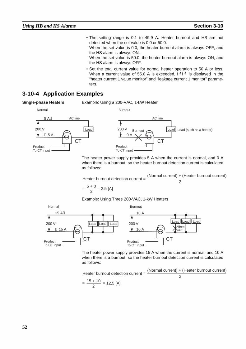
52
Using HB and HS Alarms Section 3-10
• The setting range is 0.1 to 49.9 A. Heater burnout and HS are notdetected when the set value is 0.0 or 50.0.When the set value is 0.0, the heater burnout alarm is always OFF, andthe HS alarm is always ON.When the set value is 50.0, the heater burnout alarm is always ON, andthe HS alarm is always OFF.
• Set the total current value for normal heater operation to 50 A or less.When a current value of 55.0 A is exceeded, ffff is displayed in the“heater current 1 value monitor” and “leakage current 1 monitor” parame-ters.
3-10-4 Application ExamplesSingle-phase Heaters Example: Using a 200-VAC, 1-kW Heater
The heater power supply provides 5 A when the current is normal, and 0 Awhen there is a burnout, so the heater burnout detection current is calculatedas follows:
Example: Using Three 200-VAC, 1-kW Heaters
The heater power supply provides 15 A when the current is normal, and 10 Awhen there is a burnout, so the heater burnout detection current is calculatedas follows:
CT0 A
200 V
CT
5 A→
←5 A
200 V
Normal
AC line
Load Load
AC line
ProductTo CT input
ProductTo CT input
Burnout
Load (such as a heater)Burnout
Heater burnout detection current =(Normal current) + (Heater burnout current)
2
= 5 + 02
= 2.5 [A]
10 A
10 A
CT
15 A→
←15 A
200 V
CT
200 V
Normal
ProductTo CT input
ProductTo CT input
Burnout
Load LoadLoadLoad LoadLoad
Burn-out
Heater burnout detection current =(Normal current) + (Heater burnout current)
2
= 15 + 102
= 12.5 [A]

53
Using HB and HS Alarms Section 3-10
3-10-5 Settings (HB alarm)To activate the heater burnout alarm, set the “heater burnout detection”parameter to ON in the advanced function setting level and set the “heaterburnout detection 1” parameter in the adjustment level.
Operating Procedure This procedure sets the “heater burnout detection 1” parameter to 2.5.
Moving to the Advanced Function Setting LevelThe “heater burnout detection” parameter setting is already ON by default, soset the “heater burnout detection 1” parameter.
Setting Heater Burnout Detection
Operation Level 1. Move to the advanced function setting level.Press the O key for at least three seconds to move from the operationlevel to the initial setting level.
Initial Setting Level 2. Select “move to advanced function setting level” by pressing the M key.
Initial Setting Level 3. Press the D key to enter the password (−169), and move from the initialsetting level to the advanced function setting level.
Advanced Function Setting Level The top parameter in the advanced function setting level is displayed.
4. Select the “heater burnout detection” parameter by pressing the M key.Check that this parameter is set to ON (the default).Next, set the “heater current 1 value monitor” parameter.
Operation Level 5. Press the O key for at least one second to move from the advanced func-tion setting level to the initial setting level and then to the operation level.
Adjustment Level 6. Press the O key for less than one second to move from the operation lev-el to the adjustment level.
7. Select the “heater current 1 value monitor” parameter by pressing the Mkey. Check the current value. Next, set the “heater burnout detection 1”parameter.
8. Select the “heater burnout detection 1” parameter by pressing the M key.Refer to 3-10-3 Calculating Detection Current Values on page 51 whenmaking the settings.
C
25100
PV/SP
in-t5
Input type
amov-169
Moves to ad-vanced function setting level
initoff
hbuon
Heater burnout detection
C
25100
PV/SP
atoff
AT execute/ cancel
ct10.0
Heater current 1 value monitor
hb10.0
Heater burnout detection 1
■
■
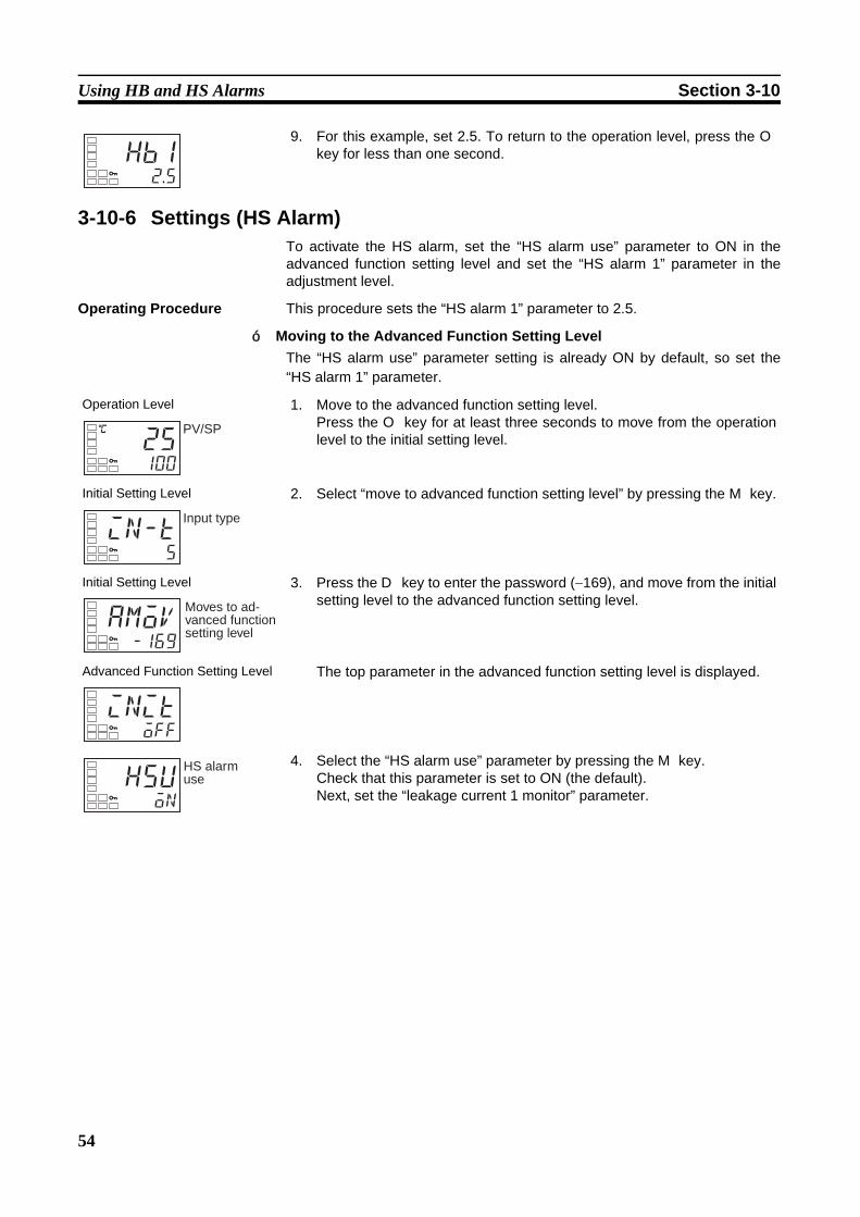
54
Using HB and HS Alarms Section 3-10
3-10-6 Settings (HS Alarm)To activate the HS alarm, set the “HS alarm use” parameter to ON in theadvanced function setting level and set the “HS alarm 1” parameter in theadjustment level.
Operating Procedure This procedure sets the “HS alarm 1” parameter to 2.5.
Moving to the Advanced Function Setting LevelThe “HS alarm use” parameter setting is already ON by default, so set the“HS alarm 1” parameter.
9. For this example, set 2.5. To return to the operation level, press the Okey for less than one second.hb1
2.5
Operation Level 1. Move to the advanced function setting level.Press the O key for at least three seconds to move from the operationlevel to the initial setting level.
Initial Setting Level 2. Select “move to advanced function setting level” by pressing the M key.
Initial Setting Level 3. Press the D key to enter the password (−169), and move from the initialsetting level to the advanced function setting level.
Advanced Function Setting Level The top parameter in the advanced function setting level is displayed.
4. Select the “HS alarm use” parameter by pressing the M key.Check that this parameter is set to ON (the default).Next, set the “leakage current 1 monitor” parameter.
C
25100
PV/SP
in-t5
Input type
amov-169
Moves to ad-vanced function setting level
initoff
hsuon
HS alarm use
■
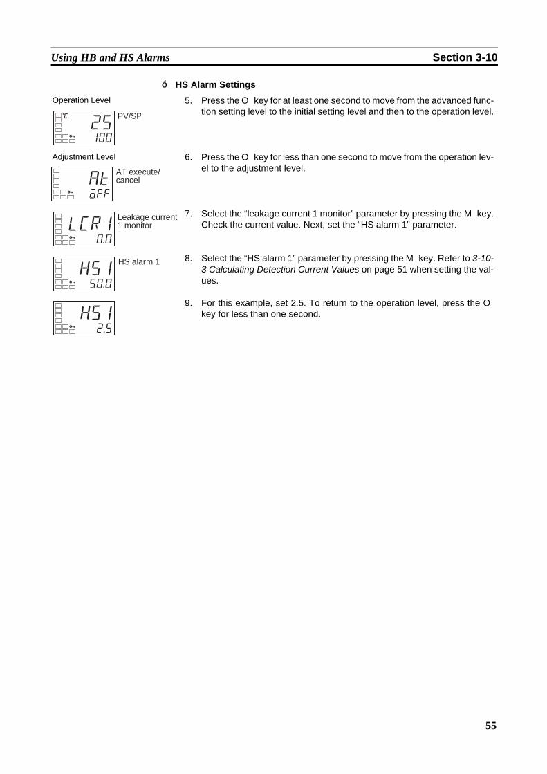
55
Using HB and HS Alarms Section 3-10
HS Alarm Settings
Operation Level 5. Press the O key for at least one second to move from the advanced func-tion setting level to the initial setting level and then to the operation level.
Adjustment Level 6. Press the O key for less than one second to move from the operation lev-el to the adjustment level.
7. Select the “leakage current 1 monitor” parameter by pressing the M key.Check the current value. Next, set the “HS alarm 1” parameter.
8. Select the “HS alarm 1” parameter by pressing the M key. Refer to 3-10-3 Calculating Detection Current Values on page 51 when setting the val-ues.
9. For this example, set 2.5. To return to the operation level, press the Okey for less than one second.
C
25100
PV/SP
atoff
AT execute/ cancel
lcr10.0
Leakage current 1 monitor
hs150.0
HS alarm 1
hs12.5
■

56
Using HB and HS Alarms Section 3-10

57
SECTION 4Applications Operations
This section describes scaling, the SP ramp function, and other special functions that can be used to make the most of thefunctionality of the E5CZ and E5CZ-U Digital Temperature Controllers.
4-1 Shifting Input Values . . . . . . . . . . . . . . . . . . . . . . . . . . . . . . . . . . . . . . . . . . . 59
4-1-1 Shifting Inputs . . . . . . . . . . . . . . . . . . . . . . . . . . . . . . . . . . . . . . . . . 59
4-1-2 How to Calculate Input Shift Values for a 2-point Shift . . . . . . . . . 60
4-2 Alarm Hysteresis. . . . . . . . . . . . . . . . . . . . . . . . . . . . . . . . . . . . . . . . . . . . . . . 63
4-2-1 Standby Sequence. . . . . . . . . . . . . . . . . . . . . . . . . . . . . . . . . . . . . . . 63
4-2-2 Alarm Latch . . . . . . . . . . . . . . . . . . . . . . . . . . . . . . . . . . . . . . . . . . . 63
4-2-3 Close in Alarm/Open in Alarm. . . . . . . . . . . . . . . . . . . . . . . . . . . . . 64
4-3 Setting Scaling Upper and Lower Limits for Analog Inputs . . . . . . . . . . . . . 65
4-3-1 Analog Input . . . . . . . . . . . . . . . . . . . . . . . . . . . . . . . . . . . . . . . . . . . 65
4-4 Executing Heating/Cooling Control . . . . . . . . . . . . . . . . . . . . . . . . . . . . . . . . 66
4-4-1 Heating/Cooling Control . . . . . . . . . . . . . . . . . . . . . . . . . . . . . . . . . 66
4-4-2 Settings . . . . . . . . . . . . . . . . . . . . . . . . . . . . . . . . . . . . . . . . . . . . . . . 68
4-5 Using Event Inputs . . . . . . . . . . . . . . . . . . . . . . . . . . . . . . . . . . . . . . . . . . . . . 69
4-5-1 Event Input Settings . . . . . . . . . . . . . . . . . . . . . . . . . . . . . . . . . . . . . 69
4-5-2 How to Use the Multi-SP Function . . . . . . . . . . . . . . . . . . . . . . . . . 69
4-5-3 Settings . . . . . . . . . . . . . . . . . . . . . . . . . . . . . . . . . . . . . . . . . . . . . . . 71
4-5-4 Executing Run/Stop Control. . . . . . . . . . . . . . . . . . . . . . . . . . . . . . . 72
4-5-5 Switching between Auto and Manual Control . . . . . . . . . . . . . . . . . 72
4-6 Setting the SP Upper and Lower Limit Values. . . . . . . . . . . . . . . . . . . . . . . . 73
4-6-1 Set Point Limiter. . . . . . . . . . . . . . . . . . . . . . . . . . . . . . . . . . . . . . . . 73
4-6-2 Setting . . . . . . . . . . . . . . . . . . . . . . . . . . . . . . . . . . . . . . . . . . . . . . . . 73
4-7 Using the SP Ramp Function to Limit the SP Change Rate . . . . . . . . . . . . . . 74
4-7-1 SP Ramp . . . . . . . . . . . . . . . . . . . . . . . . . . . . . . . . . . . . . . . . . . . . . . 74
4-8 Moving to the Advanced Function Setting Level . . . . . . . . . . . . . . . . . . . . . . 76
4-9 Using the Key Protect Level . . . . . . . . . . . . . . . . . . . . . . . . . . . . . . . . . . . . . . 77
4-9-1 Protection . . . . . . . . . . . . . . . . . . . . . . . . . . . . . . . . . . . . . . . . . . . . . 77
4-10 Alarm Delays . . . . . . . . . . . . . . . . . . . . . . . . . . . . . . . . . . . . . . . . . . . . . . . . . 79
4-10-1 Alarm Delays . . . . . . . . . . . . . . . . . . . . . . . . . . . . . . . . . . . . . . . . . . 79
4-11 Loop Break Alarm . . . . . . . . . . . . . . . . . . . . . . . . . . . . . . . . . . . . . . . . . . . . . 81
4-11-1 Loop Break Alarm (LBA) . . . . . . . . . . . . . . . . . . . . . . . . . . . . . . . . 81
4-12 Performing Manual Control . . . . . . . . . . . . . . . . . . . . . . . . . . . . . . . . . . . . . . 84
4-12-1 Manual Operation . . . . . . . . . . . . . . . . . . . . . . . . . . . . . . . . . . . . . . . 84

58
4-13 Using the Transfer Output . . . . . . . . . . . . . . . . . . . . . . . . . . . . . . . . . . . . . . . . 88
4-13-1 Transfer Output Function . . . . . . . . . . . . . . . . . . . . . . . . . . . . . . . . . 88
4-14 Output Adjustment Functions . . . . . . . . . . . . . . . . . . . . . . . . . . . . . . . . . . . . . 91
4-14-1 Output Limits . . . . . . . . . . . . . . . . . . . . . . . . . . . . . . . . . . . . . . . . . . 91

59
Shifting Input Values Section 4-1
4-1 Shifting Input Values4-1-1 Shifting Inputs
The input shift matched to the sensor currently selected in the “input type”parameter is displayed.
• A 2-point shift is applied for infrared temperature sensors. A 2-point shiftcan also be used if the “input shift type” parameter (advanced functionsetting level) is set to INS2 for a thermocouple or platinum resistancethermometer.
• There is no shift for analog inputs. Use scaling for fine adjustments.
One-point shift• With a 1-point shift, the value set for the “temperature input shift” parame-
ter (adjustment level) is applied to each point in the entire temperatureinput range. For example, if the input shift value is set to 1.2°C, the pro-cess value is treated as 201.2°C after the input shift is applied when themeasured process value is 200°C.
Operating Procedure In this example, the input from a K sensor is shifted by 1°C using a 1-pointinput shift.
insTemperature input shift
0100
Temperature
Upper limit
Lower limit
Before shifting
After shifting
Input shift value
Input
Operation Level Operation Level
Adjustment Level 1. Press the O key to move from the operation level to the adjustment level.
2. Select the “temperature input shift” parameter by pressing the M key.
3. Press the U or D key to set 1.0.
Operation Level 4. To return to the operation level, press the O key. The process value is1°C larger than before the shift was applied.
C
30200
atoff
AT execute/ cancel
C
ins0.0
Temperature input shift
C
ins1.0
C
31200
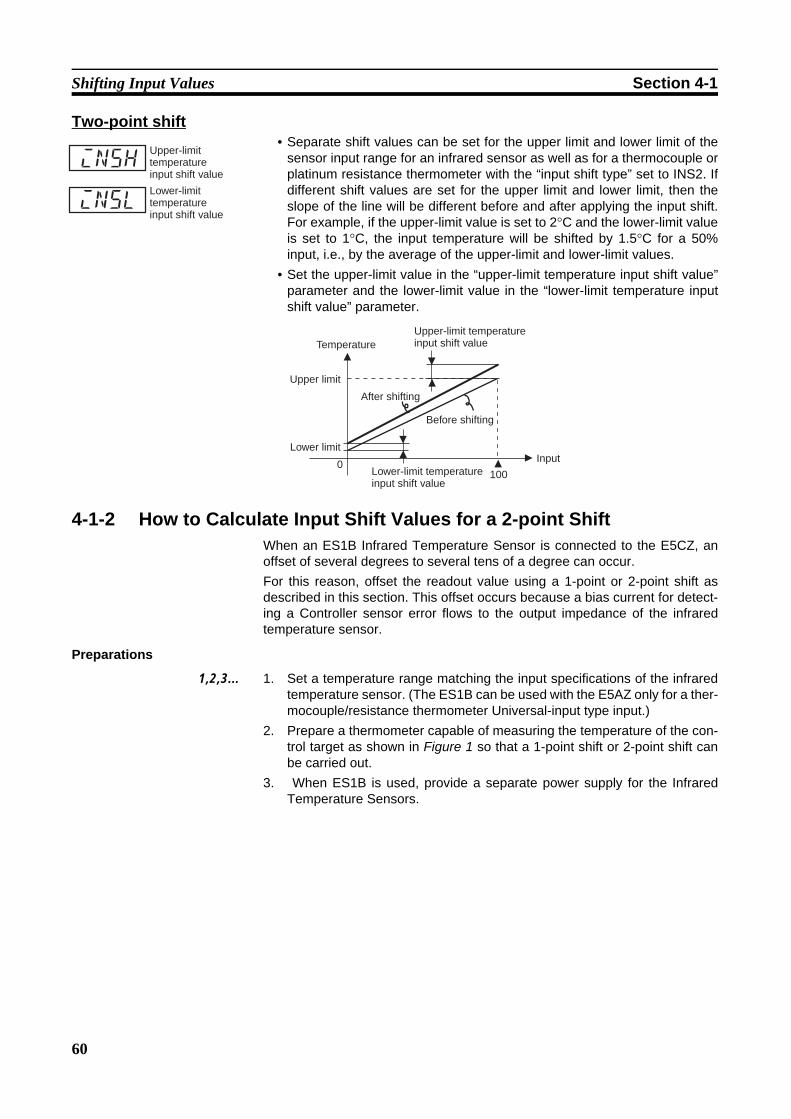
60
Shifting Input Values Section 4-1
Two-point shift• Separate shift values can be set for the upper limit and lower limit of the
sensor input range for an infrared sensor as well as for a thermocouple orplatinum resistance thermometer with the “input shift type” set to INS2. Ifdifferent shift values are set for the upper limit and lower limit, then theslope of the line will be different before and after applying the input shift.For example, if the upper-limit value is set to 2°C and the lower-limit valueis set to 1°C, the input temperature will be shifted by 1.5°C for a 50%input, i.e., by the average of the upper-limit and lower-limit values.
• Set the upper-limit value in the “upper-limit temperature input shift value”parameter and the lower-limit value in the “lower-limit temperature inputshift value” parameter.
4-1-2 How to Calculate Input Shift Values for a 2-point ShiftWhen an ES1B Infrared Temperature Sensor is connected to the E5CZ, anoffset of several degrees to several tens of a degree can occur.For this reason, offset the readout value using a 1-point or 2-point shift asdescribed in this section. This offset occurs because a bias current for detect-ing a Controller sensor error flows to the output impedance of the infraredtemperature sensor.
Preparations
1,2,3... 1. Set a temperature range matching the input specifications of the infraredtemperature sensor. (The ES1B can be used with the E5AZ only for a ther-mocouple/resistance thermometer Universal-input type input.)
2. Prepare a thermometer capable of measuring the temperature of the con-trol target as shown in Figure 1 so that a 1-point shift or 2-point shift canbe carried out.
3. When ES1B is used, provide a separate power supply for the InfraredTemperature Sensors.
insh
insl
Upper-limit temperature input shift value
Lower-limit temperature input shift value
0100
Temperature
Upper limit
Lower limit
Before shifting
After shifting
Input
Upper-limit temperature input shift value
Lower-limit temperature input shift value
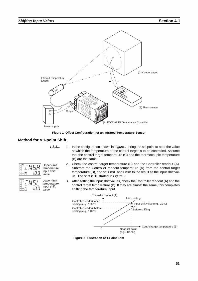
61
Shifting Input Values Section 4-1
Figure 1 Offset Configuration for an Infrared Temperature Sensor
Method for a 1-point Shift1,2,3... 1. In the configuration shown in Figure 1, bring the set point to near the value
at which the temperature of the control target is to be controlled. Assumethat the control target temperature (C) and the thermocouple temperature(B) are the same.
2. Check the control target temperature (B) and the Controller readout (A).Subtract the Controller readout temperature (A) from the control targettemperature (B), and set insl and insh to the result as the input shift val-ue. The shift is illustrated in Figure 2.
3. After setting the input shift values, check the Controller readout (A) and thecontrol target temperature (B). If they are almost the same, this completesshifting the temperature input.
Figure 2 Illustration of 1-Point Shift
Infrared Temperature Sensor
(C) Control target
(B) Thermometer
(A) E5CZ/AZ/EZ Temperature Controller
Output
Power supply
C
insh10.0
C
insl10.0
Upper-limit temperature input shift value
Lower-limit temperature input shift value
0
Controller readout (A)
Controller readout after shifting (e.g., 120°C)
Controller readout before shifting (e.g., 110°C)
Before shifting
After shifting
Input shift value (e.g., 10°C)
Near set point (e.g., 120°C)
Control target temperature (B)
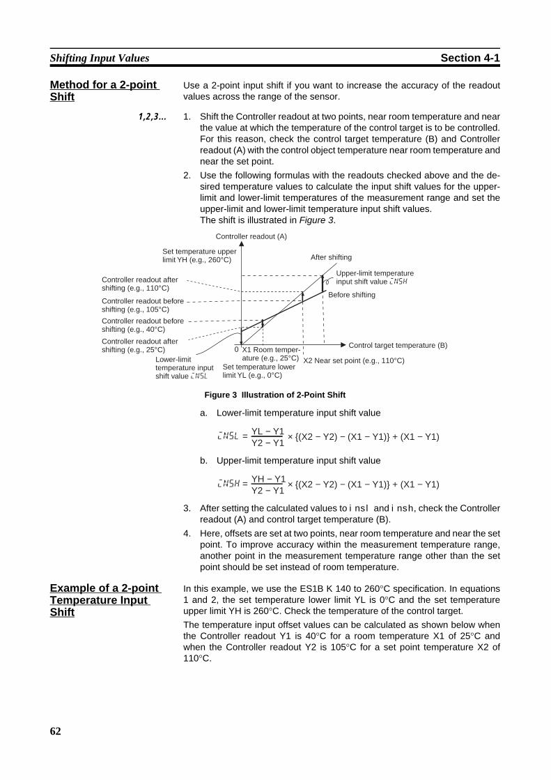
62
Shifting Input Values Section 4-1
Method for a 2-point Shift
Use a 2-point input shift if you want to increase the accuracy of the readoutvalues across the range of the sensor.
1,2,3... 1. Shift the Controller readout at two points, near room temperature and nearthe value at which the temperature of the control target is to be controlled.For this reason, check the control target temperature (B) and Controllerreadout (A) with the control object temperature near room temperature andnear the set point.
2. Use the following formulas with the readouts checked above and the de-sired temperature values to calculate the input shift values for the upper-limit and lower-limit temperatures of the measurement range and set theupper-limit and lower-limit temperature input shift values.The shift is illustrated in Figure 3.
Figure 3 Illustration of 2-Point Shift
a. Lower-limit temperature input shift value
b. Upper-limit temperature input shift value
3. After setting the calculated values to insl and insh, check the Controllerreadout (A) and control target temperature (B).
4. Here, offsets are set at two points, near room temperature and near the setpoint. To improve accuracy within the measurement temperature range,another point in the measurement temperature range other than the setpoint should be set instead of room temperature.
Example of a 2-point Temperature Input Shift
In this example, we use the ES1B K 140 to 260°C specification. In equations1 and 2, the set temperature lower limit YL is 0°C and the set temperatureupper limit YH is 260°C. Check the temperature of the control target.The temperature input offset values can be calculated as shown below whenthe Controller readout Y1 is 40°C for a room temperature X1 of 25°C andwhen the Controller readout Y2 is 105°C for a set point temperature X2 of110°C.
0
Controller readout (A)
Set temperature upper limit YH (e.g., 260°C)
Controller readout after shifting (e.g., 110°C)
Controller readout before shifting (e.g., 105°C)
Controller readout before shifting (e.g., 40°C)
Controller readout after shifting (e.g., 25°C)
After shifting
Upper-limit temperature input shift value insh
Before shifting
X1 Room temper-ature (e.g., 25°C)
Control target temperature (B)
Lower-limit temperature input shift value insl
Set temperature lower limit YL (e.g., 0°C)
X2 Near set point (e.g., 110°C)
insl = YL − Y1Y2 − Y1
× {(X2 − Y2) − (X1 − Y1)} + (X1 − Y1)
insh = YH − Y1Y2 − Y1
× {(X2 − Y2) − (X1 − Y1)} + (X1 − Y1)
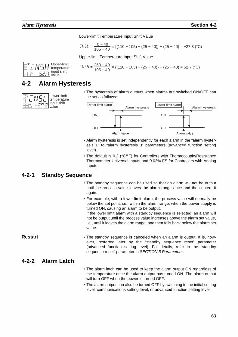
63
Alarm Hysteresis Section 4-2
Lower-limit Temperature Input Shift Value
Upper-limit Temperature Input Shift Value
4-2 Alarm Hysteresis• The hysteresis of alarm outputs when alarms are switched ON/OFF can
be set as follows:
• Alarm hysteresis is set independently for each alarm in the “alarm hyster-esis 1" to “alarm hysteresis 3” parameters (advanced function settinglevel).
• The default is 0.2 (°C/°F) for Controllers with Thermocouple/ResistanceThermometer Universal-inputs and 0.02% FS for Controllers with AnalogInputs.
4-2-1 Standby Sequence• The standby sequence can be used so that an alarm will not be output
until the process value leaves the alarm range once and then enters itagain.
• For example, with a lower limit alarm, the process value will normally bebelow the set point, i.e., within the alarm range, when the power supply isturned ON, causing an alarm to be output.If the lower limit alarm with a standby sequence is selected, an alarm willnot be output until the process value increases above the alarm set value,i.e., until it leaves the alarm range, and then falls back below the alarm setvalue.
Restart • The standby sequence is canceled when an alarm is output. It is, how-ever, restarted later by the “standby sequence reset” parameter(advanced function setting level). For details, refer to the “standbysequence reset” parameter in SECTION 5 Parameters.
4-2-2 Alarm Latch• The alarm latch can be used to keep the alarm output ON regardless of
the temperature once the alarm output has turned ON. The alarm outputwill turn OFF when the power is turned OFF.
• The alarm output can also be turned OFF by switching to the initial settinglevel, communications setting level, or advanced function setting level.
C
insl-27.3
Lower-limit temperature input shift value
insl = 0 − 40105 − 40
× {(110 − 105) − (25 − 40)} + (25 − 40) = −27.3 (°C)
C
insh52.7
Upper-limit temperature input shift value
insh = 260 − 40105 − 40
× {(110 − 105) − (25 − 40)} + (25 − 40) = 52.7 (°C)
ON
OFF
ON
OFF
Upper-limit alarmAlarm hysteresis
Alarm value
Lower-limit alarmAlarm hysteresis
Alarm value
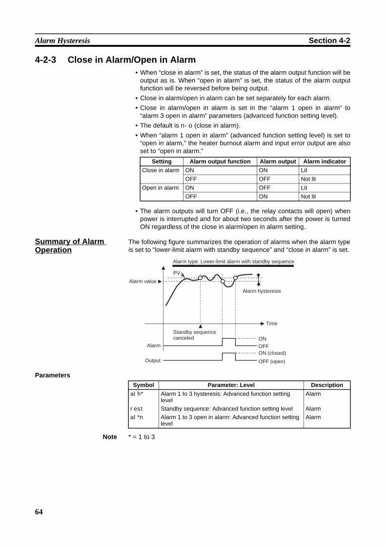
64
Alarm Hysteresis Section 4-2
4-2-3 Close in Alarm/Open in Alarm• When “close in alarm” is set, the status of the alarm output function will be
output as is. When “open in alarm” is set, the status of the alarm outputfunction will be reversed before being output.
• Close in alarm/open in alarm can be set separately for each alarm.• Close in alarm/open in alarm is set in the “alarm 1 open in alarm” to
“alarm 3 open in alarm” parameters (advanced function setting level).• The default is n-o (close in alarm).• When “alarm 1 open in alarm” (advanced function setting level) is set to
“open in alarm,” the heater burnout alarm and input error output are alsoset to “open in alarm.”
• The alarm outputs will turn OFF (i.e., the relay contacts will open) whenpower is interrupted and for about two seconds after the power is turnedON regardless of the close in alarm/open in alarm setting.
Summary of Alarm Operation
The following figure summarizes the operation of alarms when the alarm typeis set to “lower-limit alarm with standby sequence” and “close in alarm” is set.
Parameters
Note * = 1 to 3
Setting Alarm output function Alarm output Alarm indicatorClose in alarm ON ON Lit
OFF OFF Not litOpen in alarm ON OFF Lit
OFF ON Not lit
OFFON
PV
Alarm type: Lower-limit alarm with standby sequence
Alarm value
Alarm hysteresis
Time
Standby sequence canceled
Alarm
Output OFF (open)
ON (closed)
Symbol Parameter: Level Descriptionalh*
rest
al*n
Alarm 1 to 3 hysteresis: Advanced function setting levelStandby sequence: Advanced function setting levelAlarm 1 to 3 open in alarm: Advanced function setting level
Alarm
AlarmAlarm
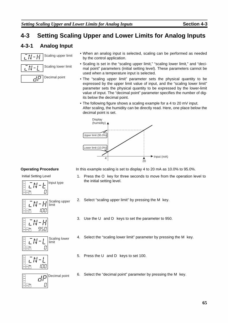
65
Setting Scaling Upper and Lower Limits for Analog Inputs Section 4-3
4-3 Setting Scaling Upper and Lower Limits for Analog Inputs4-3-1 Analog Input
• When an analog input is selected, scaling can be performed as neededby the control application.
• Scaling is set in the “scaling upper limit,” “scaling lower limit,” and “deci-mal point” parameters (initial setting level). These parameters cannot beused when a temperature input is selected.
• The “scaling upper limit” parameter sets the physical quantity to beexpressed by the upper limit value of input, and the “scaling lower limit”parameter sets the physical quantity to be expressed by the lower-limitvalue of input. The “decimal point” parameter specifies the number of dig-its below the decimal point.
• The following figure shows a scaling example for a 4 to 20 mV input.After scaling, the humidity can be directly read. Here, one place below thedecimal point is set.
Operating Procedure In this example scaling is set to display 4 to 20 mA as 10.0% to 95.0%.
in-h
in-l
dp
Scaling upper limit
Scaling lower limit
Decimal point
420
Display (humidity)
Upper limit (95.0%)
Lower limit (10.0%)
Input (mA)
Initial Setting Level 1. Press the O key for three seconds to move from the operation level tothe initial setting level.
2. Select “scaling upper limit” by pressing the M key.
3. Use the U and D keys to set the parameter to 950.
4. Select the “scaling lower limit” parameter by pressing the M key.
5. Press the U and D keys to set 100.
6. Select the “decimal point” parameter by pressing the M key.
in-t0
Input type
in-h100
Scaling upper limit
in-h950
in-l0
Scaling lower limit
in-l100
dp0
Decimal point

66
Executing Heating/Cooling Control Section 4-4
4-4 Executing Heating/Cooling Control4-4-1 Heating/Cooling Control
Heating/cooling control operates when h-c (heating/cooling) is selected forthe “standard or heating/cooling” parameter.The following functions are assigned to outputs in the initial status.
Each output is automatically initialized as shown below when the controlmode is changed.
Example: E5CZ
Note For the E5AZ/EZ, alarm 3 is assigned for control output (cooling) (alarm out-put 2 is assigned for alarm 2).
• The heating/cooling operation of the control outputs will switch when the“direct/reverse operation” parameter is set to “direct.”
• When heating/cooling control is selected, the “dead band” and “coolingcoefficient” parameters can be used.
In this manual, assigned control outputs and alarm outputs are indicated asfollows: “Control output 1 must be assigned” or “Alarm 1 must be assigned.”
7. Press the U and D keys to set 1.
8. To return to the operation level, press the O key for one second.
dp1
Parameter name Symbol Initial statusControl output 1 assignment out1 Control output for heatingAlarm output 1 assignment alm1 Alarm 1Alarm output 2 assignment alm2 Alarm 2Alarm output 3 assignment (E5AZ/EZ only)
alm3 Alarm 3
Parameter name Symbol Standard Heating/coolingControl output 1 assignment out1 Control output for heating Control output for heatingAlarm output 1 assignment alm1 Alarm 1 Alarm 1Alarm output 2 assignment alm2 Alarm 2 (See note.) Control output for cooling (See note.)
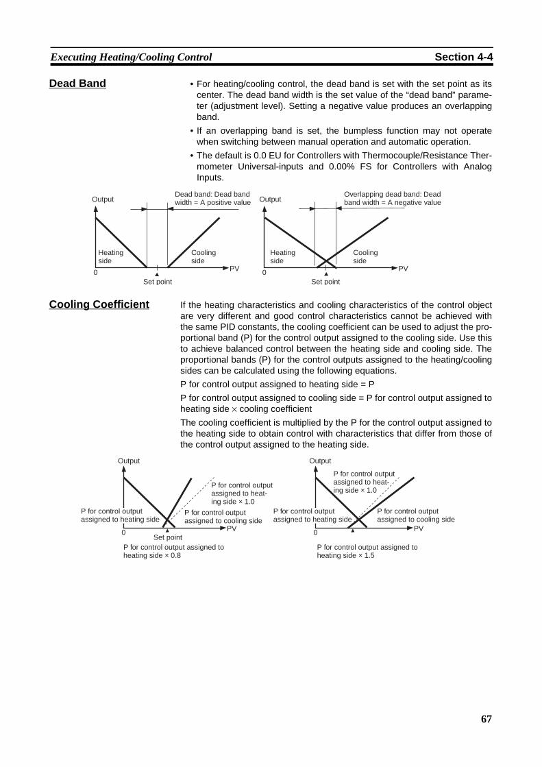
67
Executing Heating/Cooling Control Section 4-4
Dead Band • For heating/cooling control, the dead band is set with the set point as itscenter. The dead band width is the set value of the “dead band” parame-ter (adjustment level). Setting a negative value produces an overlappingband.
• If an overlapping band is set, the bumpless function may not operatewhen switching between manual operation and automatic operation.
• The default is 0.0 EU for Controllers with Thermocouple/Resistance Ther-mometer Universal-inputs and 0.00% FS for Controllers with AnalogInputs.
Cooling Coefficient If the heating characteristics and cooling characteristics of the control objectare very different and good control characteristics cannot be achieved withthe same PID constants, the cooling coefficient can be used to adjust the pro-portional band (P) for the control output assigned to the cooling side. Use thisto achieve balanced control between the heating side and cooling side. Theproportional bands (P) for the control outputs assigned to the heating/coolingsides can be calculated using the following equations.P for control output assigned to heating side = PP for control output assigned to cooling side = P for control output assigned toheating side × cooling coefficientThe cooling coefficient is multiplied by the P for the control output assigned tothe heating side to obtain control with characteristics that differ from those ofthe control output assigned to the heating side.
PV0 PV0
OutputDead band: Dead band width = A positive value Output
Heating side
Cooling side
Set point
Overlapping dead band: Dead band width = A negative value
Heating side
Cooling side
Set point
PV0 PV0
Output Output
P for control output assigned to heating side
P for control output assigned to heat-ing side × 1.0
P for control output assigned to cooling side
Set pointP for control output assigned to heating side × 0.8
P for control output assigned to heating side
P for control output assigned to heat-ing side × 1.0
P for control output assigned to cooling side
P for control output assigned to heating side × 1.5

68
Executing Heating/Cooling Control Section 4-4
4-4-2 SettingsTo set heating/cooling control, set the “standard or heating/cooling,” “deadband,” and “cooling coefficient” parameters.
Setting Heating/Cooling ControlOperating Procedure Standard or heating/cooling = Heating/cooling
Setting the Cooling CoefficientOperating Procedure Cooling Coefficient = 10
Setting the Dead BandOperating Procedure Dead Band = 5
Initial Setting Level 1. Press the O key for at least three seconds to move from the operationlevel to the initial setting level.
2. Select “heating/cooling control” in the initial setting level.stnd: Standard controlh-c: Heating/cooling control
s-hcstnd
Standard or heating/cooling
Adjustment Level 1. Select the “cooling coefficient” in the adjustment level.
2. Use the U key to set the parameter to 10.00.
c-sc1.00
Cooling coefficient
c-sc10.00
Adjustment Level 1. Select the “dead band” parameter in the adjustment level.
2. Use the U key to set the parameter to 5.0.
C
c-db0.0
Dead band
C
c-db5.0
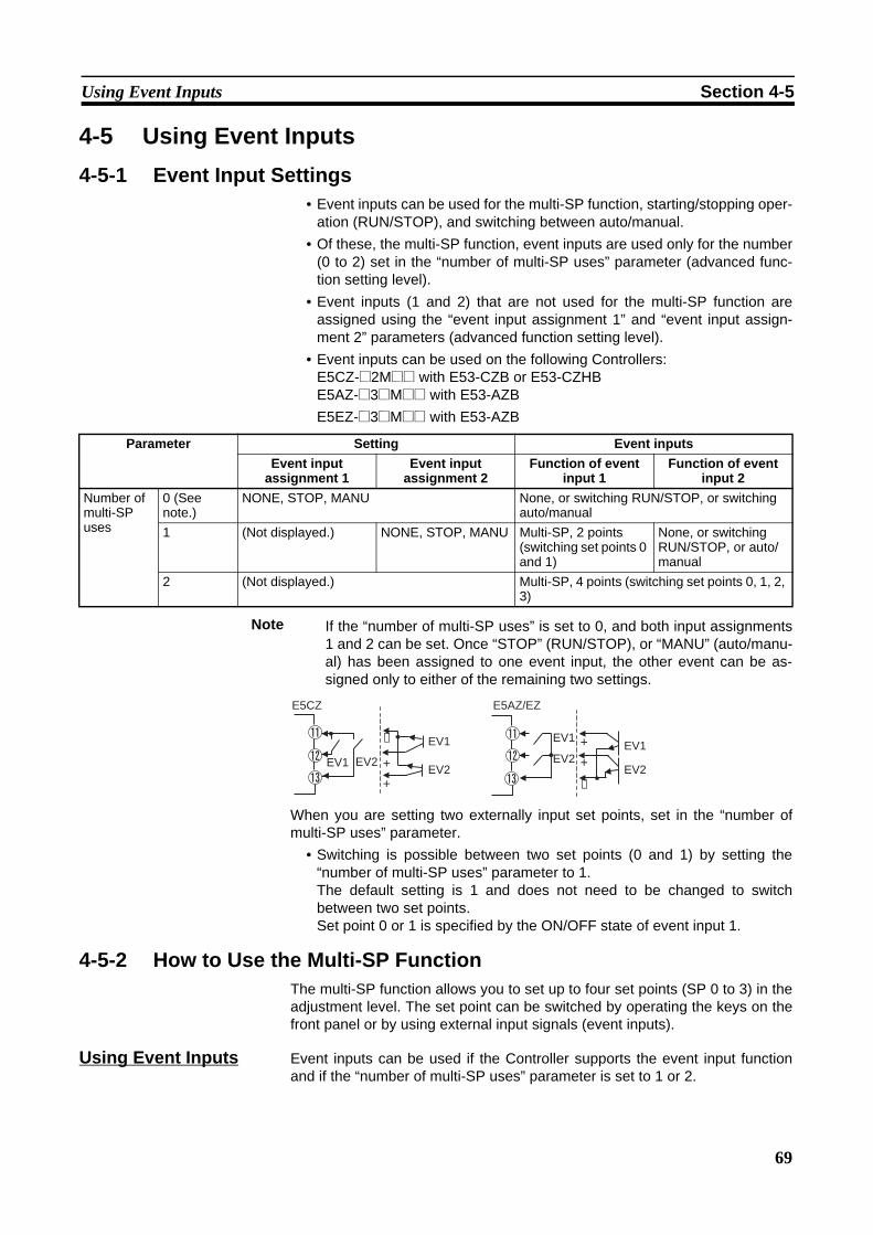
69
Using Event Inputs Section 4-5
4-5 Using Event Inputs4-5-1 Event Input Settings
• Event inputs can be used for the multi-SP function, starting/stopping oper-ation (RUN/STOP), and switching between auto/manual.
• Of these, the multi-SP function, event inputs are used only for the number(0 to 2) set in the “number of multi-SP uses” parameter (advanced func-tion setting level).
• Event inputs (1 and 2) that are not used for the multi-SP function areassigned using the “event input assignment 1” and “event input assign-ment 2” parameters (advanced function setting level).
• Event inputs can be used on the following Controllers:E5CZ-@2M@@ with E53-CZB or E53-CZHBE5AZ-@3@M@@ with E53-AZBE5EZ-@3@M@@ with E53-AZB
If the “number of multi-SP uses” is set to 0, and both input assignments1 and 2 can be set. Once “STOP” (RUN/STOP), or “MANU” (auto/manu-al) has been assigned to one event input, the other event can be as-signed only to either of the remaining two settings.
When you are setting two externally input set points, set in the “number ofmulti-SP uses” parameter.
• Switching is possible between two set points (0 and 1) by setting the“number of multi-SP uses” parameter to 1. The default setting is 1 and does not need to be changed to switchbetween two set points. Set point 0 or 1 is specified by the ON/OFF state of event input 1.
4-5-2 How to Use the Multi-SP FunctionThe multi-SP function allows you to set up to four set points (SP 0 to 3) in theadjustment level. The set point can be switched by operating the keys on thefront panel or by using external input signals (event inputs).
Using Event Inputs Event inputs can be used if the Controller supports the event input functionand if the “number of multi-SP uses” parameter is set to 1 or 2.
Parameter Setting Event inputsEvent input
assignment 1Event input
assignment 2Function of event
input 1Function of event
input 2Number of multi-SP uses
0 (See note.)
NONE, STOP, MANU None, or switching RUN/STOP, or switching auto/manual
1 (Not displayed.) NONE, STOP, MANU Multi-SP, 2 points (switching set points 0 and 1)
None, or switching RUN/STOP, or auto/manual
2 (Not displayed.) Multi-SP, 4 points (switching set points 0, 1, 2, 3)
E5CZ
EV2EV2
EV1
EV1−
+
+
E5AZ/EZ
EV2
EV1
−
+
+EV2
EV1
Note
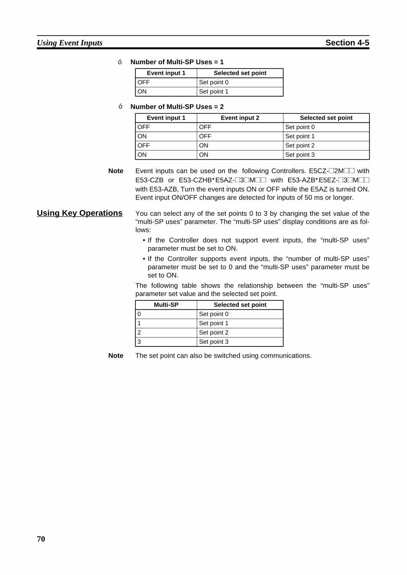
70
Using Event Inputs Section 4-5
Number of Multi-SP Uses = 1
Number of Multi-SP Uses = 2
Note Event inputs can be used on the following Controllers. E5CZ-@2M@@ withE53-CZB or E53-CZHB,E5AZ-@3@M@@ with E53-AZB,E5EZ-@3@M@@with E53-AZB.Turn the event inputs ON or OFF while the E5AZ is turned ON.Event input ON/OFF changes are detected for inputs of 50 ms or longer.
Using Key Operations You can select any of the set points 0 to 3 by changing the set value of the“multi-SP uses” parameter. The “multi-SP uses” display conditions are as fol-lows:
• If the Controller does not support event inputs, the “multi-SP uses”parameter must be set to ON.
• If the Controller supports event inputs, the “number of multi-SP uses”parameter must be set to 0 and the “multi-SP uses” parameter must beset to ON.
The following table shows the relationship between the “multi-SP uses”parameter set value and the selected set point.
Note The set point can also be switched using communications.
Event input 1 Selected set pointOFF Set point 0ON Set point 1
Event input 1 Event input 2 Selected set pointOFF OFF Set point 0ON OFF Set point 1OFF ON Set point 2ON ON Set point 3
Multi-SP Selected set point0 Set point 01 Set point 12 Set point 23 Set point 3
■
■
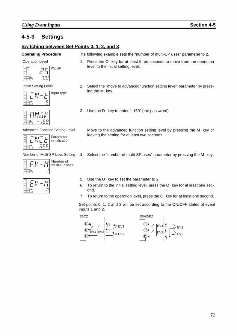
71
Using Event Inputs Section 4-5
4-5-3 Settings
Switching between Set Points 0, 1, 2, and 3Operating Procedure The following example sets the “number of multi-SP uses” parameter to 2.
Set points 0, 1, 2 and 3 will be set according to the ON/OFF states of eventinputs 1 and 2.
Operation Level 1. Press the O key for at least three seconds to move from the operationlevel to the initial setting level.
Initial Setting Level 2. Select the “move to advanced function setting level” parameter by press-ing the M key.
3. Use the D key to enter “−169” (the password).
Advanced Function Setting Level Move to the advanced function setting level by pressing the M key orleaving the setting for at least two seconds.
Number of Multi-SP Uses Setting 4. Select the “number of multi-SP uses” parameter by pressing the M key.
5. Use the U key to set the parameter to 2.6. To return to the initial setting level, press the O key for at least one sec-
ond.7. To return to the operation level, press the O key for at least one second.
C
25100
PV/SP
in-t5
Input type
amov-169
initoff
Parameter initialization
ev-m1
Number of multi-SP uses
ev-m2
E5CZ
EV2EV2
EV1
EV1−
++
E5AZ/EZ
EV2
EV1
EV2
EV1
−
+
+
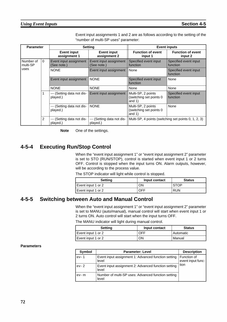
72
Using Event Inputs Section 4-5
Event input assignments 1 and 2 are as follows according to the setting of the“number of multi-SP uses” parameter:
Note One of the settings.
4-5-4 Executing Run/Stop ControlWhen the “event input assignment 1” or “event input assignment 2” parameteris set to STO (RUN/STOP), control is started when event input 1 or 2 turnsOFF. Control is stopped when the input turns ON. Alarm outputs, however,will be according to the process value.The STOP indicator will light while control is stopped.
4-5-5 Switching between Auto and Manual ControlWhen the “event input assignment 1” or “event input assignment 2” parameteris set to MANU (auto/manual), manual control will start when event input 1 or2 turns ON. Auto control will start when the input turns OFF. The MANU indicator will light during manual control.
Parameters
Parameter Setting Event inputsEvent input
assignment 1Event input
assignment 2Function of event
input 1Function of event
input 2Number of multi-SP uses
0 Event input assignment (See note.)
Event input assignment (See note.)
Specified event input function
Specified event input function
NONE Event input assignment None Specified event input function
Event input assignment NONE Specified event input function
None
NONE NONE None None1 --- (Setting data not dis-
played.)Event input assignment Multi-SP, 2 points
(switching set points 0 and 1)
Specified event input function
--- (Setting data not dis-played.)
NONE Multi-SP, 2 points (switching set points 0 and 1)
None
2 --- (Setting data not dis-played.)
--- (Setting data not dis-played.)
Multi-SP, 4 points (switching set points 0, 1, 2, 3)
Setting Input contact StatusEvent input 1 or 2 ON STOPEvent input 1 or 2 OFF RUN
Setting Input contact StatusEvent input 1 or 2 OFF AutomaticEvent input 1 or 2 ON Manual
Symbol Parameter: Level Descriptionev-1 Event input assignment 1: Advanced function setting
levelFunction of event input func-tionev-2 Event input assignment 2: Advanced function setting
levelev-m Number of multi-SP uses: Advanced function setting
level
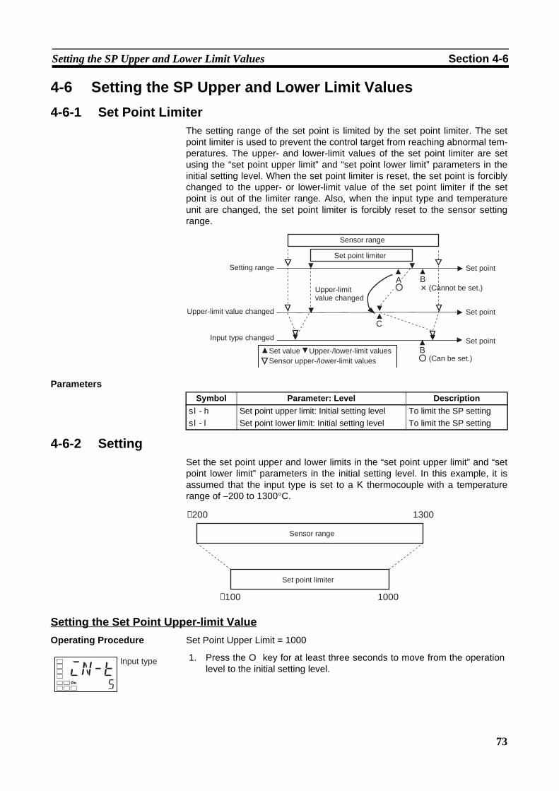
73
Setting the SP Upper and Lower Limit Values Section 4-6
4-6 Setting the SP Upper and Lower Limit Values4-6-1 Set Point Limiter
The setting range of the set point is limited by the set point limiter. The setpoint limiter is used to prevent the control target from reaching abnormal tem-peratures. The upper- and lower-limit values of the set point limiter are setusing the “set point upper limit” and “set point lower limit” parameters in theinitial setting level. When the set point limiter is reset, the set point is forciblychanged to the upper- or lower-limit value of the set point limiter if the setpoint is out of the limiter range. Also, when the input type and temperatureunit are changed, the set point limiter is forcibly reset to the sensor settingrange.
Parameters
4-6-2 SettingSet the set point upper and lower limits in the “set point upper limit” and “setpoint lower limit” parameters in the initial setting level. In this example, it isassumed that the input type is set to a K thermocouple with a temperaturerange of −200 to 1300°C.
Setting the Set Point Upper-limit ValueOperating Procedure Set Point Upper Limit = 1000
A
C
B
B
Sensor range
Set point limiter
Setting range
Upper-limit value changed
Input type changed
Upper-limit value changed
Set point
(Cannot be set.)
Set point
Set point
(Can be set.) Set value Upper-/lower-limit valuesSensor upper-/lower-limit values
Symbol Parameter: Level Descriptionsl-h
sl-l
Set point upper limit: Initial setting levelSet point lower limit: Initial setting level
To limit the SP settingTo limit the SP setting
−200 1300
−100 1000
Sensor range
Set point limiter
1. Press the O key for at least three seconds to move from the operationlevel to the initial setting level.in-t
5
Input type
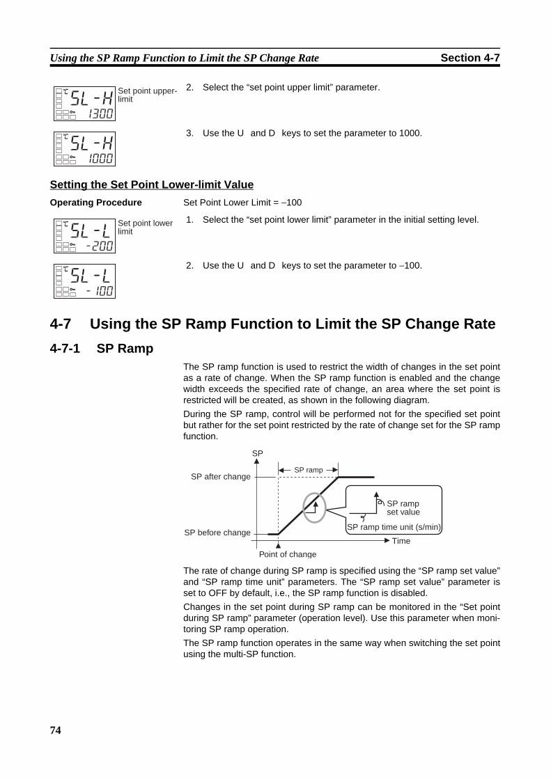
74
Using the SP Ramp Function to Limit the SP Change Rate Section 4-7
Setting the Set Point Lower-limit ValueOperating Procedure Set Point Lower Limit = −100
4-7 Using the SP Ramp Function to Limit the SP Change Rate4-7-1 SP Ramp
The SP ramp function is used to restrict the width of changes in the set pointas a rate of change. When the SP ramp function is enabled and the changewidth exceeds the specified rate of change, an area where the set point isrestricted will be created, as shown in the following diagram. During the SP ramp, control will be performed not for the specified set pointbut rather for the set point restricted by the rate of change set for the SP rampfunction.
The rate of change during SP ramp is specified using the “SP ramp set value”and “SP ramp time unit” parameters. The “SP ramp set value” parameter isset to OFF by default, i.e., the SP ramp function is disabled.Changes in the set point during SP ramp can be monitored in the “Set pointduring SP ramp” parameter (operation level). Use this parameter when moni-toring SP ramp operation.The SP ramp function operates in the same way when switching the set pointusing the multi-SP function.
2. Select the “set point upper limit” parameter.
3. Use the U and D keys to set the parameter to 1000.
C
sl-h1300
Set point upper-limit
C
sl-h1000
1. Select the “set point lower limit” parameter in the initial setting level.
2. Use the U and D keys to set the parameter to −100.
C
sl-l-200
Set point lower limit
C
sl-l-100
SP
SP rampSP after change
SP before change
Point of change
Time
SP ramp set value
SP ramp time unit (s/min)
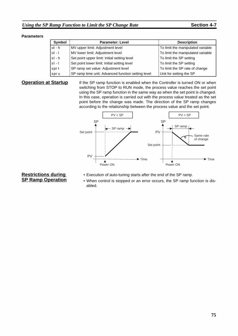
75
Using the SP Ramp Function to Limit the SP Change Rate Section 4-7
Parameters
Operation at Startup If the SP ramp function is enabled when the Controller is turned ON or whenswitching from STOP to RUN mode, the process value reaches the set pointusing the SP ramp function in the same way as when the set point is changed.In this case, operation is carried out with the process value treated as the setpoint before the change was made. The direction of the SP ramp changesaccording to the relationship between the process value and the set point.
Restrictions during SP Ramp Operation
• Execution of auto-tuning starts after the end of the SP ramp.• When control is stopped or an error occurs, the SP ramp function is dis-
abled.
Symbol Parameter: Level Descriptionol-h
ol-l
sl-h
sl-l
sprt
spru
MV upper limit: Adjustment levelMV lower limit: Adjustment levelSet point upper limit: Initial setting levelSet point lower limit: Initial setting levelSP ramp set value: Adjustment levelSP ramp time unit: Advanced function setting level
To limit the manipulated variableTo limit the manipulated variableTo limit the SP settingTo limit the SP settingTo limit the SP rate of changeUnit for setting the SP
SP SP
PV
PV
PV < SP
SP rampSet point
Time Time
Power ON Power ON
PV > SP
SP ramp
Same rate of change
Set point
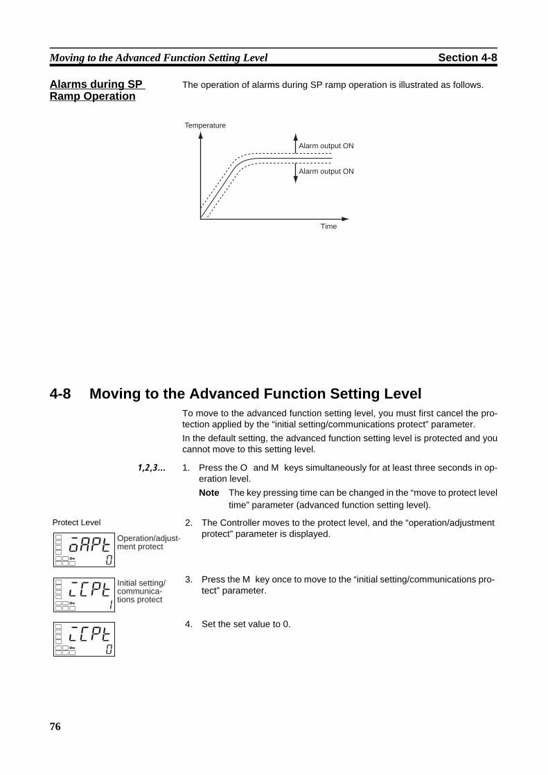
76
Moving to the Advanced Function Setting Level Section 4-8
Alarms during SP Ramp Operation
The operation of alarms during SP ramp operation is illustrated as follows.
4-8 Moving to the Advanced Function Setting LevelTo move to the advanced function setting level, you must first cancel the pro-tection applied by the “initial setting/communications protect” parameter. In the default setting, the advanced function setting level is protected and youcannot move to this setting level.
1,2,3... 1. Press the O and M keys simultaneously for at least three seconds in op-eration level.Note The key pressing time can be changed in the “move to protect level
time” parameter (advanced function setting level).
Temperature
Time
Alarm output ON
Alarm output ON
Protect Level 2. The Controller moves to the protect level, and the “operation/adjustmentprotect” parameter is displayed.
3. Press the M key once to move to the “initial setting/communications pro-tect” parameter.
4. Set the set value to 0.
oapt0
Operation/adjust-ment protect
icpt1
Initial setting/ communica-tions protect
icpt0

77
Using the Key Protect Level Section 4-9
4-9 Using the Key Protect Level4-9-1 Protection
• To move to the protect level, press the O and M keys simultaneously forat least three seconds in operation level or adjustment level. (See note.)Note The key pressing time can be changed in the “move to protect level
time” parameter (advanced function setting level).• The protect level protects parameters that are not changed during Con-
troller operation until operation is started to prevent them from being mod-ified unintentionally. There are three types of protection: operation/adjustment protect, initialsetting/communications protect, and setting change protect.
• The protect level settings restrict the range of parameters that can beused.
Operation Level 5. Press the O and M keys simultaneously for at least one second to returnto the operation level.
Initial Setting Level 6. Move to the advanced function setting level.Press the O key for at least three seconds to move from the operationlevel to the initial setting level.
Initial Setting Level 7. Select the “move to advanced function setting level” parameter by press-ing the M key.
Advanced function setting level 8. Press the D key, enter the password (−169), and then either press theM key or leave the setting for at least two seconds to move to the ad-vanced function setting level from the initial setting level.
Initial Setting Level 9. To return to the initial setting level, press the O key for at least one sec-ond.
Operation Level 10. To return to the operation level, press the O key for at least one second.
C
25100
PV/SP
in-t5
Input type
amov-169
Move to ad-vanced function setting level
initoff
Parameter initialization
in-t5
Input type
C
25100
PV/SP
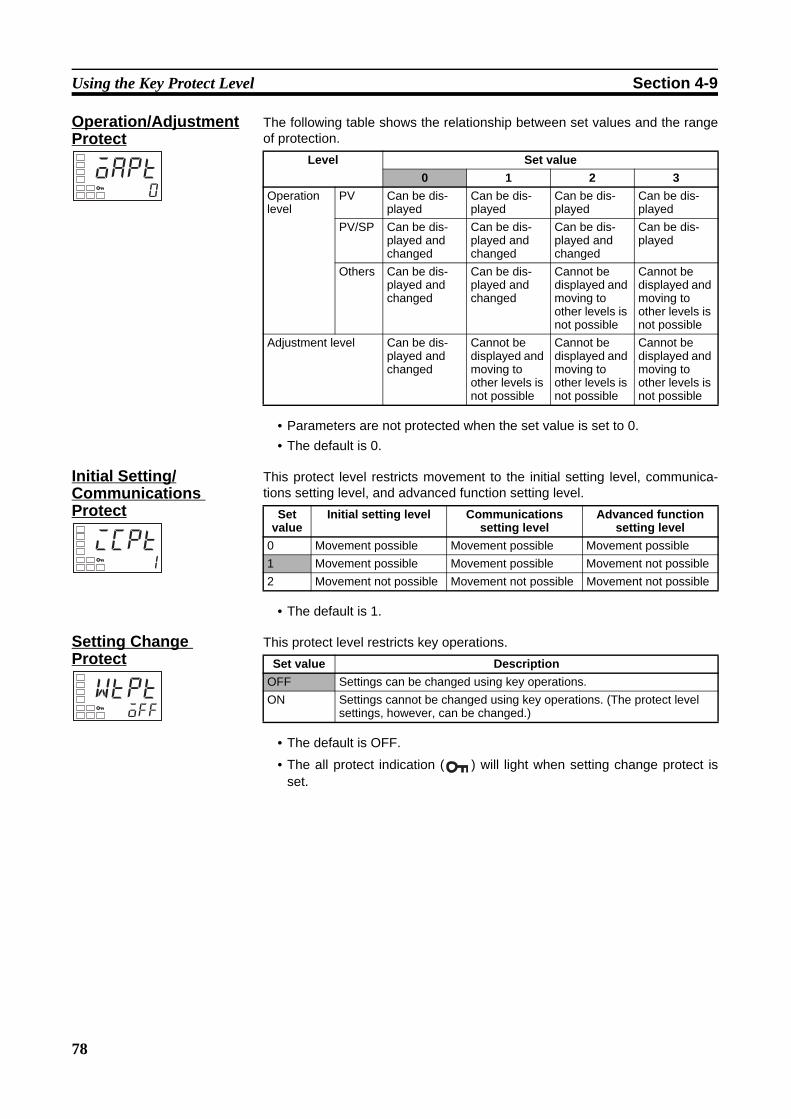
78
Using the Key Protect Level Section 4-9
Operation/Adjustment Protect
The following table shows the relationship between set values and the rangeof protection.
• Parameters are not protected when the set value is set to 0.• The default is 0.
Initial Setting/Communications Protect
This protect level restricts movement to the initial setting level, communica-tions setting level, and advanced function setting level.
• The default is 1.
Setting Change Protect
This protect level restricts key operations.
• The default is OFF.
• The all protect indication ( ) will light when setting change protect isset.
oapt0
Level Set value0 1 2 3
Operation level
PV Can be dis-played
Can be dis-played
Can be dis-played
Can be dis-played
PV/SP Can be dis-played and changed
Can be dis-played and changed
Can be dis-played and changed
Can be dis-played
Others Can be dis-played and changed
Can be dis-played and changed
Cannot be displayed and moving to other levels is not possible
Cannot be displayed and moving to other levels is not possible
Adjustment level Can be dis-played and changed
Cannot be displayed and moving to other levels is not possible
Cannot be displayed and moving to other levels is not possible
Cannot be displayed and moving to other levels is not possible
icpt1
Set value
Initial setting level Communications setting level
Advanced function setting level
0 Movement possible Movement possible Movement possible1 Movement possible Movement possible Movement not possible2 Movement not possible Movement not possible Movement not possible
wtptoff
Set value DescriptionOFF Settings can be changed using key operations.ON Settings cannot be changed using key operations. (The protect level
settings, however, can be changed.)

79
Alarm Delays Section 4-10
4-10 Alarm Delays4-10-1 Alarm Delays
• Delays can be set for the alarm outputs. ON and OFF delays can be setseparately for alarms 1, 2, and 3. The ON and OFF delays for alarm 1function only for the alarm function. If the alarm output 1 is set to be out-put as an OR with other alarm functions (i.e., the heater burnout alarm,HS alarm, or input error output alarm), the delays will not function for theother alarms. The ON and OFF delays for alarms 1, 2, and 3 also apply tothe individual ALM1, ALM2, and ALM3 indicators and to communicationsstatus. The alarm ON delays will also function when power is turned ONor when moving from initial setting level to operation level (i.e., to softwareresets). All outputs will turn OFF and the OFF delays will not functionwhen moving to the initial setting level or when an alarm is output for aheater burnout error.
Operation of Alarm ON and OFF Delays (for an Upper-limit Alarm)
• The alarm will not turn ON if the time that the alarm is ON is equal to orless than the ON delay set time. Also, the alarm will not turn OFF if thetime that the alarm is OFF is equal to or less than the OFF delay set time.
• If an alarm turns OFF and then back ON during the ON delay time, thetime will be remeasured from the last time the alarm turns ON. Also, if analarm turns ON and then back OFF during the OFF delay time, the timewill be remeasured from the last time the alarm turns OFF.
Parameters Related to Alarm Delays
PV
Alarm settingAlarm hysteresis
Alarm status
ON delay set time
ON delay set time
OFF delay set time
Alarm Latch = OFF
Alarm will not turn ON.
Parameter name Symbol Set (monitor) valuesAlarm 1 ON delay a1on 0 to 999 (s)Alarm 2 ON delay a2on 0 to 999 (s)Alarm 3 ON delay a3on 0 to 999 (s)Alarm 1 OFF delay a1of 0 to 999 (s)Alarm 2 OFF delay a2of 0 to 999 (s)Alarm 3 OFF delay a3of 0 to 999 (s)
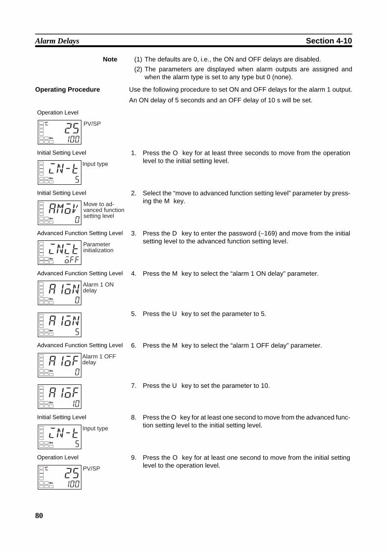
80
Alarm Delays Section 4-10
Note (1) The defaults are 0, i.e., the ON and OFF delays are disabled.(2) The parameters are displayed when alarm outputs are assigned and
when the alarm type is set to any type but 0 (none).
Operating Procedure Use the following procedure to set ON and OFF delays for the alarm 1 output.
An ON delay of 5 seconds and an OFF delay of 10 s will be set.
Operation Level
Initial Setting Level 1. Press the O key for at least three seconds to move from the operationlevel to the initial setting level.
Initial Setting Level 2. Select the “move to advanced function setting level” parameter by press-ing the M key.
Advanced Function Setting Level 3. Press the D key to enter the password (−169) and move from the initialsetting level to the advanced function setting level.
Advanced Function Setting Level 4. Press the M key to select the “alarm 1 ON delay” parameter.
5. Press the U key to set the parameter to 5.
Advanced Function Setting Level 6. Press the M key to select the “alarm 1 OFF delay” parameter.
7. Press the U key to set the parameter to 10.
Initial Setting Level 8. Press the O key for at least one second to move from the advanced func-tion setting level to the initial setting level.
Operation Level 9. Press the O key for at least one second to move from the initial settinglevel to the operation level.
C
25100
PV/SP
in-t5
Input type
amov0
Move to ad-vanced function setting level
initoff
Parameter initialization
a1on0
Alarm 1 ON delay
a1on5
a1of0
Alarm 1 OFF delay
a1of10
in-t5
Input type
C
25100
PV/SP

81
Loop Break Alarm Section 4-11
4-11 Loop Break Alarm4-11-1 Loop Break Alarm (LBA)
• With a loop break alarm, there is assumed to be an error in the controlloop if the control deviation (SP − PV) is greater than the threshold set inthe “LBA level” parameter and if the control deviation is not reduced by atleast the value set in the “LBA detection band” parameter within the LBAdetection time.
• Loop break alarms are detected at the following times.
If the control deviation is reduced in the area between 1 and 2 (i.e., the setpoint is approached) and the amount the control deviation is reduced is atleast equal to the LBA band, the loop break alarm will remain OFF. The process value is within the LBA level between 3 and 4, and thus loopbreak alarms will not be detected. (The loop break alarm will remain OFF.) If the process value is outside the LBA level between 4 and 5 and the controldeviation is not reduced by at least the LBA band within the LBA detectiontime, the loop break alarm will turn ON.If the control deviation is reduced in the area between 5 and 6 (i.e., the setpoint is approached) and the amount the control deviation is reduced is atleast equal to the LBA band, the loop break alarm will turn OFF.If the control deviation is reduced in the area between 6 and 7 (i.e., the setpoint is approached) and the amount the control deviation is reduced is lessthan the LBA band, the loop break alarm will turn ON.
• If the LBA detection time, LBA level, LBA detection band, and PID set-tings are not appropriate, alarms may be detected inappropriately oralarms may not be output when necessary.
• Loop break alarms may be detected if unexpectedly large disturbancesoccur continuously and a large deviation does not decrease.
• If a loop break occurs when the set point is near the ambient temperature,the temperature deviation in a steady state may be less than the LBAlevel, preventing detection of the loop break.
• If the set point is so high or low that it cannot be reached even with a sat-urated manipulated variable, a temperature deviation may remain even ina steady state and a loop break may be detected.
LBA ONLBA ON LBA OFFLBA OFF(1)(2) (3) (4) (5) (6) (7)
Set point
LBA detec-tion time
Area where LBA is not detected
LBA detection time LBA detection
time
LBA detection time
LBA band LBA band
LBA band
LBA level
LBA level

82
Loop Break Alarm Section 4-11
• Detection is not possible if a fault occurs that causes an increase in tem-perature while control is being applied to increase the temperature (e.g.,an SSR short-circuit fault).
• Detection is not possible if a fault occurs that causes a decrease in tem-perature while control is being applied to decrease the temperature (e.g.,a heater burnout fault).
Parameters Related to Loop Break Alarms
Note Set “none” as the unit for analog inputs.
• A loop break alarm can be output by setting the alarm 1 type to 12 (LBA).• The ALM1 indicator will light when a loop break is detected.• Loop breaks are not detected during SP ramp operation.• Loop breaks are not detected during auto-tuning, manual operation, or
while stopped.• If the alarm 1 latch is set to ON, the latch will be effective for the loop
break alarm.
Automatically Setting the LBA Detection Time
• The LBA detection time is automatically set by auto-tuning. (It is not set automatically, however, for heating/cooling control.)
• If the optimum LBA detection time is not obtained by auto-tuning, set the“LBA detection time” parameter (advanced function setting level).
Determining the LBA Detection Time
• To manually set the LBA detection time, set the “LBA detection time”parameter to twice the LBA reference time given below.
1,2,3... 1. Set the output to the maximum value.2. Measure the time required for the width of change in the input to reach the
LBA band.
Parameter name Symbol Setting range RemarksLBA detection time lba 0 to 9999 (s) Setting 0 disables the LBA
function.LBA level lbal Controllers with Thermo-
couple/Resistance Ther-mometer Universal-inputs
0.1 to 999.9 (°C/°F) (See note.)
Default: 8.0 (°C/°F)
Controllers with Analog Inputs
0.01 to 99.99 (%FS) Default: 10.00% FS
LBA band lbab Controllers with Thermo-couple/Resistance Ther-mometer Universal-inputs
0.0 to 999.9 (°C/°F) (See note.)
Default: 3.0 (°C/°F)
Controllers with Analog Inputs
0.00 to 99.99 (%FS) Default: 0.20% FS
MV = 100%
PVTemperature
Time
Measurement time Tm
LBA band
LBA detection time = Tm × 2

83
Loop Break Alarm Section 4-11
3. Set the “LBA detection time” parameter to two times the measured time.
LBA Level • Set the control deviation when the control loop is working properly.• The default is 8.0 (°C/°F) for Controllers with Thermocouple/Resistance
Thermometer Universal-inputs and 10.00% FS for Controllers with AnalogInputs.
LBA Band • There is assumed to be an error in the control loop if the control deviationis greater than the threshold set in the “LBA level” parameter and if thecontrol deviation does not change by at least the value set in the “LBAband” parameter.
• The default is 3.0 (°C/°F) for Controllers with Thermocouple/ResistanceThermometer Universal-inputs and 0.20% FS for Controllers with AnalogInputs.
Operating Procedure Perform the following procedure to use the loop break alarm.In this example, the LBA detection time is set to 10, the LBA level is set to 8.0,and the LBA band is set to 3.0.
Operation Level
Initial Setting Level 1. Press the O key for at least three seconds to move from the operationlevel to the initial setting level.
Initial Setting Level 2. Select the “alarm 1 type” parameter by pressing the M key.
Initial Setting Level 3. Press the U key to set the parameter to 12.
4. Select the “move to advanced function setting level” parameter by press-ing the M key.
Advanced Function Setting Level 5. Press the D key to enter the password (−169), and move from the initialsetting level to the advanced function setting level.
Advanced Function Setting Level 6. Select the “LBA detection time” parameter by pressing the M key.
C
25100
PV/SP
in-t5
Input type
alt12
Alarm 1 type
alt112
amov0
Move to ad-vanced function setting level
initoff
Parameter initialization
lba0
LBA detection time

84
Performing Manual Control Section 4-12
4-12 Performing Manual Control4-12-1 Manual Operation
• The manipulated variable can be set in manual mode if the “PV/MV”parameter is displayed in the manual control level. The final MV used inautomatic mode will be used as the initial manual MV when moving fromautomatic mode to manual mode. In manual mode, the change value willbe fixed immediately and reflected in the actual MV.
• The automatic display return function will not operate in manual mode. • Balanceless-bumpless operation will be performed for the MV when
switching from manual operation to automatic operation. (See note.)• If a power interruption occurs during manual operation, manual operation
will be restarted when power is restored using the same MV as whenpower was interrupted.
• Switching between automatic and manual operation is possible for a max-imum of one million times.
• Manual operation can be used only for PID control.
7. Press the U key to set the parameter to 10.
Advanced Function Setting Level 8. Select the “LBA level” parameter by pressing the M key.
9. Press the U key to set the parameter to 8.0. (The default is 8.0.)
Advanced Function Setting Level 10. Select the “LBA band” parameter by pressing the M key.
11. Press the U or D key to set the parameter to 3.0. (The default is 3.0.)
Initial Setting Level 12. Press the O key for at least one second to move from the advanced func-tion setting level to the initial setting level.
Operation Level 13. Press the O key for at least one second to move from the initial settinglevel to the operation level.
C
lba10
C
lbal8.0
LBA level
C
lbal8.0
C
lbab3.0
LBA band
C
lbab3.0
in-t5
Input type
C
25100
PV/SP

85
Performing Manual Control Section 4-12
Note In balanceless-bumpless operation, the MV before switching is used initiallyafter the switch and then gradually changed to achieve the proper value afterswitch to prevent radical changes in the MV after switching operation.
The overall manual operation is illustrated in the following figure.
Related Displays and Parameters
Note Refer to 4-14 Output Adjustment Functions for information on the priority forthe MV.
Moving to the Manual Control Level
• When the O key is pressed for at least 3 seconds in the operation level'sauto/manual switching display, the manual mode will be entered and themanual control level will be displayed. It is not possible to move to anydisplays except for the “PV/MV” parameter during manual operation.Press the O key for at least one section from the “PV/MV” display inmanual control level to return to automatic mode and display the topparameter in the operation level.
0ONOFF
MV (%)
Time
Balanceless-bumpless
Manual
Automatic
MV switched
Power in-terrupted
Parameter name Symbol Level RemarksPV/MV (manual MV) --- Manual Control Level −5.0 to 105.0 (heating/cooling control: −105.0 to
105.0)Auto/manual switch a-m Operation Level Switches between automatic and manual
modes.Auto/manual select addi-tion
amad Advanced Function Setting Level
Enables switching between automatic and man-ual modes.

86
Performing Manual Control Section 4-12
• If an event input is set to “MANU” (auto/manual), the “auto/manual switch”parameter will not be displayed. Use the event input to switch betweenautomatic and manual modes.
Auto/Manual Select Addition
• The “auto/manual select addition” parameter must be set to ON in theadvanced function setting level before it is possible to move to manualmode. The default is OFF.
Note (1) Priority of Manual MV and Other FunctionsEven when operation is stopped, the manual MV is given priority. Auto-tuning and self-tuning will stop when manual mode is entered.
(2) Manual MV and SP RampIf operating, the SP ramp function will continue even when manual modeis entered.
C
M
M
M
C
C
M
a-m
25
25100
2520
Press O key for at least 1 s.
a-m
m-sp0
Operation Level
Manual Control Level
PV/MVPress O key for at least 3 s.
a-m display flashes for at least 1 s.
PV
PV/SP
Auto/manual switch
Multi-SP
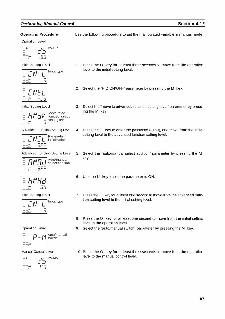
87
Performing Manual Control Section 4-12
Operating Procedure Use the following procedure to set the manipulated variable in manual mode.
Operation Level
Initial Setting Level 1. Press the O key for at least three seconds to move from the operationlevel to the initial setting level.
2. Select the “PID ON/OFF” parameter by pressing the M key.
Initial Setting Level 3. Select the “move to advanced function setting level” parameter by press-ing the M key.
Advanced Function Setting Level 4. Press the D key to enter the password (−169), and move from the initialsetting level to the advanced function setting level.
Advanced Function Setting Level 5. Select the “auto/manual select addition” parameter by pressing the Mkey.
6. Use the U key to set the parameter to ON.
Initial Setting Level 7. Press the O key for at least one second to move from the advanced func-tion setting level to the initial setting level.
8. Press the O key for at least one second to move from the initial settinglevel to the operation level.
Operation Level 9. Select the “auto/manual switch” parameter by pressing the M key.
Manual Control Level 10. Press the O key for at least three seconds to move from the operationlevel to the manual control level.
C
25100
PV/SP
in-t5
Input type
cntlpid
amov0
Move to ad-vanced function setting level
initoff
Parameter initialization
amadoff
Auto/manual select addition
amadon
in-t5
Input type
a-mAuto/manual switch
C
250.0
PV/MV

88
Using the Transfer Output Section 4-13
4-13 Using the Transfer Output4-13-1 Transfer Output Function
• If a control output is a linear current output it can be used as a transferoutput. To use the transfer output, set the “transfer output type” parame-ter to any setting other than OFF. (When the “transfer output type” parameter is set to any setting other thanOFF, the “transfer output upper limit” and “transfer output lower limit”parameters will be enabled.)
Transfer Output Type
Note (1) The default is OFF. If the transfer type is set to OFF, the item assigned inthe “control output 1 assignment” parameter will be output on control out-put 1.
(2) The difference between the transfer output value and the linear currentoutput value is illustrated in the following figure.If the linear output is used as the transfer output when the linear currentoutput type is set to 4 to 20 mA, 4.0 mA will be output for 0% and 20.0mA will be output for 100%. When a linear output is used for the control output, 3.7 mA is output for0% and 20.3 mA is output for 100% when the control output for heatingis selected to ensure that the control object is controlled at 0% and 100%.
11. Press the U or D key to set the manual MV. (In this example, the MV isset to 500%.)
Note The manual MV setting must be fixed (see page 12), but valueschanged with key operations are reflected in the control outputimmediately.
Operation Level 12. Press the O key for at least one second to move from the manual controllevel to the operation level.
C
2550.0
C
25100
PV/SP
Transfer output type Symbol Setting rangeOFF (See note 1.) off ---Set point sp SP lower limit to SP upper limitSet point during SP ramp sp-m SP lower limit to SP upper limitPV pv Sensor setting range lower limit to Sensor
setting range upper limit or Scaling lower limit to Scaling upper limit
MV monitor (heating) mv −5.0 to 105.0 (heating/cooling control: 0.0 to 105.0) (See note 2.)
MV monitor (cooling) c-mv 0.0 to 105.0 (See note 2.)

89
Using the Transfer Output Section 4-13
Transfer Scaling • Reverse scaling is possible by setting the “transfer output lower limit”parameter larger than the “transfer output upper limit” parameter. If the“transfer output lower limit” and “transfer output upper limit” parametersare set to the same value when 4 to 20 mA is set, the transfer output willbe output continuously at 0% (4 mA).
• If the SP, SP during SP ramp, or PV is selected, the “transfer output lowerlimit” and “transfer output upper limit” parameters will be forcibly initializedto the respective upper and lower setting limits for changes in the upperand lower limits of the SP limiter and the temperature unit. If the MV for heating or MV for cooling is selected, the “transfer outputlower limit” and “transfer output upper limit” parameters will be initializedto 100.0 and 0.0, respectively, when a switch is made between standardcontrol and heating/cooling control using the “standard or heating/cooling”parameter.
• The output current when the linear current type is set to 4 to 20 mA, thetransfer output upper limit is set to 90.0, and the transfer output lower limitis set to 10.0 is shown in the following graph.
• For scaling from 0.0% to 100.0%, the output for −5.0 to 0.0 will be thesame value as for 0.0%, and the output for 100.0 to 105.0 will be thesame value as for 100.0%
20.320
43.7
0100
Output current (mA)
Transfer output valueControl output
MV (%)
(The above graph is for when the linear current output type is set to 4 to 20 mA.)
10090100
20
4
Output current (mA)
MV (%)
Transfer output lower limit
Transfer output upper limit
(The above graph is for when the linear current output type is set to 4 to 20 mA.)

90
Using the Transfer Output Section 4-13
Operating Procedure The following procedure sets the transfer output for an SP range of −50 to200.
Operation Level
Initial Setting Level 1. Press the O key for at least 3 seconds to move from the operation levelto the initial setting level.
Initial Setting Level 2. Select the “transfer output type” parameter by pressing the M key.
3. Press the U key to select sp (set point).
Initial Setting Level 4. Select the “transfer output upper limit” parameter by pressing the M key.
5. Use the D key to set the parameter to 200. The default is 1300.
Initial Setting Level 6. Select the “transfer output lower limit” parameter by pressing the M key.
7. Use the U key to set the parameter to −50. The default is −200.
Operation Level 8. To return to the operation level, press the O key for at least 1 second.
C
25100
PV/SP
in-t5
Input type
tr-toff
Transfer output type
tr-tsp
C
tr-h1300
Transfer output upper limit
C
tr-h200
C
tr-l-200
Transfer output lower limit
C
tr-l-50
C
25100
PV/SP
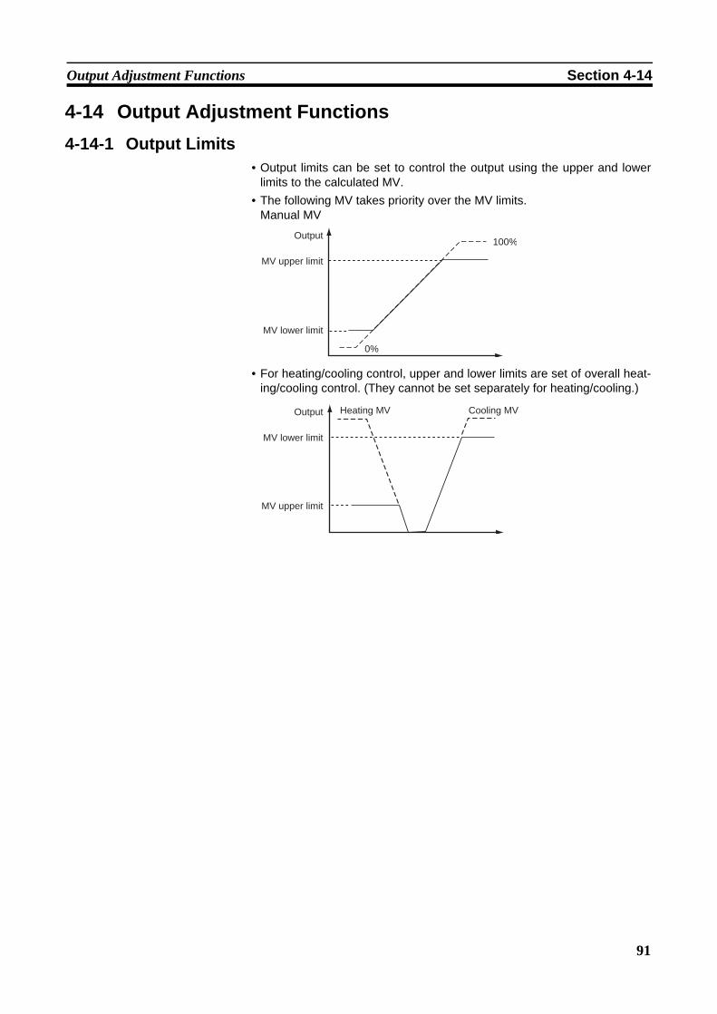
91
Output Adjustment Functions Section 4-14
4-14 Output Adjustment Functions4-14-1 Output Limits
• Output limits can be set to control the output using the upper and lowerlimits to the calculated MV.
• The following MV takes priority over the MV limits.Manual MV
• For heating/cooling control, upper and lower limits are set of overall heat-ing/cooling control. (They cannot be set separately for heating/cooling.)
0%
100%Output
MV upper limit
MV lower limit
Output
MV lower limit
MV upper limit
Heating MV Cooling MV

92
Output Adjustment Functions Section 4-14

93
SECTION 5Parameters
This section describes the individual parameters used to setup, control, and monitor operation.
5-1 Conventions Used in this Section . . . . . . . . . . . . . . . . . . . . . . . . . . . . . . . . . . 94
5-1-1 Meanings of Icons Used in this Section . . . . . . . . . . . . . . . . . . . . . . 94
5-1-2 About Related Parameter Displays. . . . . . . . . . . . . . . . . . . . . . . . . . 94
5-1-3 About the Order in Which Parameters Are Described in This Section 94
5-2 Protect Level . . . . . . . . . . . . . . . . . . . . . . . . . . . . . . . . . . . . . . . . . . . . . . . . . . 95
5-3 Operation Level. . . . . . . . . . . . . . . . . . . . . . . . . . . . . . . . . . . . . . . . . . . . . . . . 97
5-4 Adjustment Level . . . . . . . . . . . . . . . . . . . . . . . . . . . . . . . . . . . . . . . . . . . . . . 106
5-5 Manual Control Level . . . . . . . . . . . . . . . . . . . . . . . . . . . . . . . . . . . . . . . . . . . 117
5-6 Initial Setting Level. . . . . . . . . . . . . . . . . . . . . . . . . . . . . . . . . . . . . . . . . . . . . 118
5-7 Advanced Function Setting Level. . . . . . . . . . . . . . . . . . . . . . . . . . . . . . . . . . 129
5-8 Communications Setting Level . . . . . . . . . . . . . . . . . . . . . . . . . . . . . . . . . . . . 149
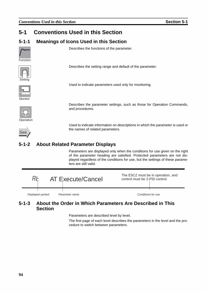
94
Conventions Used in this Section Section 5-1
5-1 Conventions Used in this Section5-1-1 Meanings of Icons Used in this Section
Describes the functions of the parameter.
Describes the setting range and default of the parameter.
Used to indicate parameters used only for monitoring.
Describes the parameter settings, such as those for Operation Commands,and procedures.
Used to indicate information on descriptions in which the parameter is used orthe names of related parameters.
5-1-2 About Related Parameter DisplaysParameters are displayed only when the conditions for use given on the rightof the parameter heading are satisfied. Protected parameters are not dis-played regardless of the conditions for use, but the settings of these parame-ters are still valid.
5-1-3 About the Order in Which Parameters Are Described in This Section
Parameters are described level by level. The first page of each level describes the parameters in the level and the pro-cedure to switch between parameters.
Function
Setting
Monitor
Operation
SeeSee
at
Displayed symbol
AT Execute/Cancel
Parameter name
The E5CZ must be in operation, and control must be 2-PID control.
Conditions for use

95
Protect Level Section 5-2
5-2 Protect LevelThree levels of protection are provided on the E5CZ, operation/adjustmentprotect, initial setting/communications protect, and setting change protect.These protect levels prevent unwanted operation of the keys on the frontpanel in varying degrees.
To move from the operation level to the protect level, press O and M keysfor three seconds (See note.) or more.
Note The time taken to move to the protect level can be adjusted by changing the“Move to protect level time” parameter setting.
Parameters that are protected will not be displayed and their settings cannotbe changed.
Control in Progress
Operation Level
Adjustment Level
Protect Level
Power ON
Press the O Key less than 1 s.
Press the O + M Keys for at least 1 s.
Press the O + M keys; display will flash.
Press the O + M Keys for at least 3 s. (See note.)
25100
C
Protect Level
M
M
M
oapt0
icpt1
wtptoff
Page
Operation/Adjustment Protect
Initial Setting/Communications Protect
Setting Change Protect
96
96
96
96
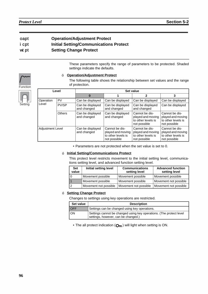
96
Protect Level Section 5-2
These parameters specify the range of parameters to be protected. Shadedsettings indicate the defaults.
Operation/Adjustment ProtectThe following table shows the relationship between set values and the rangeof protection.
• Parameters are not protected when the set value is set to 0.
Initial Setting/Communications ProtectThis protect level restricts movement to the initial setting level, communica-tions setting level, and advanced function setting level.
Setting Change ProtectChanges to settings using key operations are restricted.
• The all protect indication ( ) will light when setting is ON.
oapt Operation/Adjustment Protecticpt Initial Setting/Communications Protectwtpt Setting Change Protect
Function
Setting
Level Set value0 1 2 3
Operation Level
PV Can be displayed Can be displayed Can be displayed Can be displayedPV/SP Can be displayed
and changedCan be displayed and changed
Can be displayed and changed
Can be displayed
Others Can be displayed and changed
Can be displayed and changed
Cannot be dis-played and moving to other levels is not possible
Cannot be dis-played and moving to other levels is not possible
Adjustment Level Can be displayed and changed
Cannot be dis-played and moving to other levels is not possible
Cannot be dis-played and moving to other levels is not possible
Cannot be dis-played and moving to other levels is not possible
Set value
Initial setting level Communications setting level
Advanced function setting level
0 Movement possible Movement possible Movement possible1 Movement possible Movement possible Movement not possible2 Movement not possible Movement not possible Movement not possible
Set value DescriptionOFF Settings can be changed using key operations. ON Settings cannot be changed using key operations. (The protect level
settings, however, can be changed.)
■
■
■
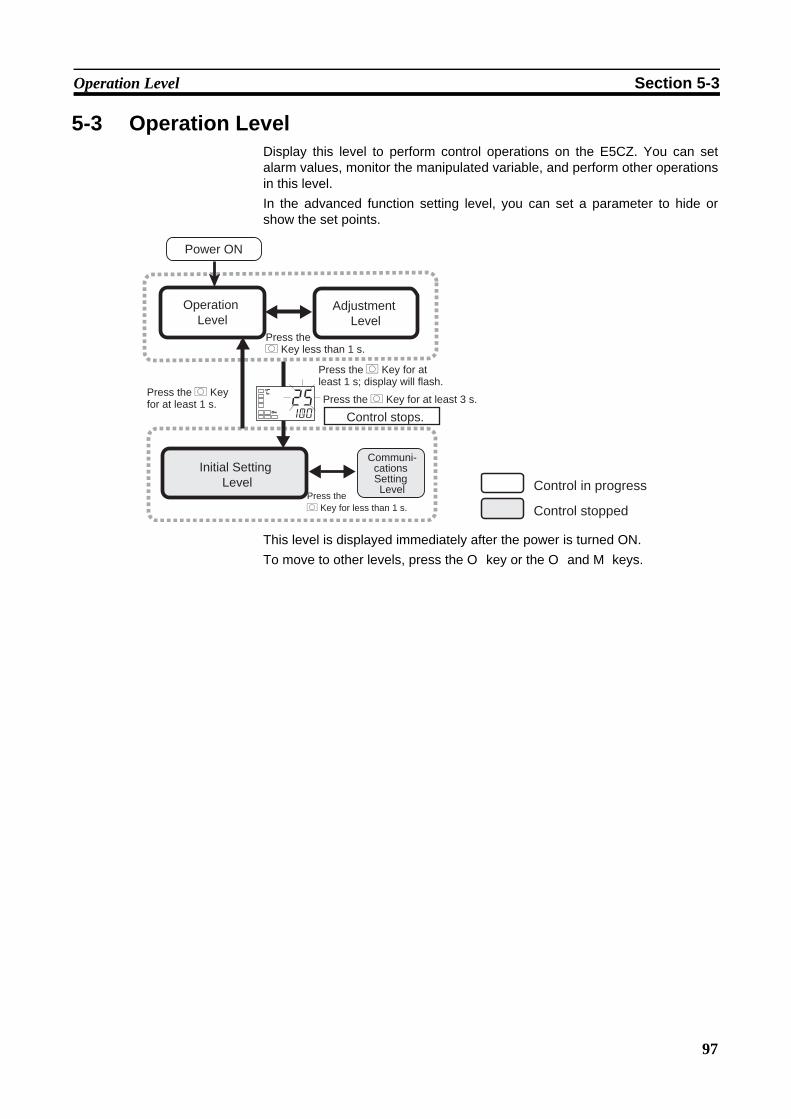
97
Operation Level Section 5-3
5-3 Operation LevelDisplay this level to perform control operations on the E5CZ. You can setalarm values, monitor the manipulated variable, and perform other operationsin this level. In the advanced function setting level, you can set a parameter to hide orshow the set points.
This level is displayed immediately after the power is turned ON. To move to other levels, press the O key or the O and M keys.
Control in progress
Control stopped
Operation Level
Initial Setting Level
Control stops.
Communi- cations Setting Level
Adjustment Level
Power ON
Press the O Key less than 1 s.
Press the O Key for at least 1 s.
Press the O Key for at least 1 s; display will flash.
Press the O Key for at least 3 s.
Press the O Key for less than 1 s.
25100
C
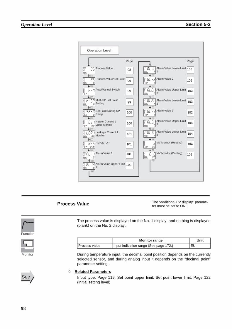
98
Operation Level Section 5-3
The process value is displayed on the No. 1 display, and nothing is displayed(blank) on the No. 2 display.
During temperature input, the decimal point position depends on the currentlyselected sensor, and during analog input it depends on the “decimal point”parameter setting.
Related ParametersInput type: Page 119, Set point upper limit, Set point lower limit: Page 122(initial setting level)
Operation Level
M
M
M
M
M
M
M
M
M
M
M
M
M
M
M
M
M
M
M
a-m
m-sp0
25C
250
C
sp-m0
C
ct10.0
lcr10.0
r-srun
al-10
C
al1h0
C
al1l0
C
al-20
C
al2h0
C
al2l0
C
al-30
C
al3h0
C
al3l0
C
o0.0
c-o0.0
Page Page
Process Value
Process Value/Set Point
Auto/Manual Switch
Heater Current 1 Value Monitor
Leakage Current 1 Monitor
RUN/STOP
Alarm Value 1
Alarm Value 2
Alarm Value 3
MV Monitor (Heating)
MV Monitor (Cooling)
Multi-SP Set Point Setting
Alarm Value Upper-Limit 1
Alarm Value Lower-Limit 1
Alarm Value Upper-Limit 2
Alarm Value Lower-Limit 2
Alarm Value Upper-Limit 3
Alarm Value Lower-Limit 3
Set Point During SP Ramp
98
99
99
99
100
100
101
101
101
103
103
102
103
103
102
104
104
104
105
Process Value The “additional PV display” parame-ter must be set to ON.
Monitor range UnitProcess value Input indication range (See page 172.) EU
Function
Monitor
SeeSee■
99
Operation Level Section 5-3
The process value is displayed on the No. 1 display, and the set point is dis-played on the No. 2 display.
During temperature input, the decimal point position depends on the currentlyselected sensor, and during analog input it depends on the “decimal point”parameter setting. Refer to the “process value” parameter.
• This parameter switches the Controller between automatic and manualmodes.
• If the O key is pressed for at least 3 seconds when the “auto/manualswitch” parameter is displayed, the manual mode will be entered and themanual control level will be displayed.
• This parameter will not be displayed if an event input is set to “MANU”(auto/manual).
Related ParametersPID ON/OFF (initial setting level): Page 122Auto/manual select addition (advanced function setting level): Page 143
To use the multi-SP function, preset the four set points (SP 0 to 3) in theadjustment level, and then switch the set point either by operating the keys orby using external input signals (event inputs). This parameter is used to select set points 0 to 3.
Process Value/Set Point
Monitor range UnitProcess value Input indication range (See page 172.) EU
Setting range UnitSet point SP lower limit to SP upper limit EU
Function
SeeSee
a-m Auto/Manual Switch
The “event input assignment 1/2” parameters must not be set to “auto/manual” and the “auto/manual select addition” parameter must be set to ON. The control must be set to 2-PID control.
Function
SeeSee
m-spMulti-SP Set Point Setting (Set Points 0 to 3)
The “multi-SP uses” parameter must be set to ON.
Function
■
100
Operation Level Section 5-3
This parameter monitors the set point during SP ramp operation.A ramp is used to restrict the change width of the set point as a rate ofchange. This parameter is displayed when a set value is input for the “SP ramp setvalue” (adjustment level). When not in ramp operation, the set point will be the same as the one dis-played for the “process value/set point” parameter.
Related ParametersProcess value/set point (operation level): Page 99SP ramp set value (adjustment level): Page 116Set point upper limit, Set point lower limit (initial setting level): Page 122
This parameter measures the heater current from the CT input used fordetecting heater burnout.This parameter measures and displays the heater current value.
• Heater burnouts are not detected if the control output (heating) ON time is190 ms or less.
• ffff is displayed when 55.0 A is exceeded. • If a heater burnout is detected, the HA indicator will light, and the relative
setting level will flash on the No. 1 display.
Related ParametersHeater burnout detection 1 (adjustment level): Page 110HB ON/OFF (advanced function setting level): Page 135Error Displays ct1: Page 158
sp-m Set Point During SP RampThe “SP ramp set value” parameter must not be set to OFF.The “ST” parameter must be set to OFF.
Monitor range UnitSP: SP lower limit to SP upper limit EU
Function
Monitor
SeeSee
ct1 Heater Current 1 Value Monitor
Heater burnout and HS alarms must be supported. Alarm 1 must be assigned.The “heater burnout detection” parameter must be set to ON.
Monitor range Unit0.0 to 55.0 A
Function
Monitor
SeeSee
■
■
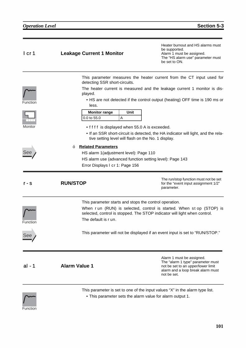
101
Operation Level Section 5-3
This parameter measures the heater current from the CT input used fordetecting SSR short-circuits.The heater current is measured and the leakage current 1 monitor is dis-played.
• HS are not detected if the control output (heating) OFF time is 190 ms orless.
• ffff is displayed when 55.0 A is exceeded. • If an SSR short-circuit is detected, the HA indicator will light, and the rela-
tive setting level will flash on the No. 1 display.
Related ParametersHS alarm 1(adjustment level): Page 110HS alarm use (advanced function setting level): Page 143Error Displays lcr1: Page 156
This parameter starts and stops the control operation.When run (RUN) is selected, control is started. When stop (STOP) isselected, control is stopped. The STOP indicator will light when control. The default is run.
This parameter will not be displayed if an event input is set to “RUN/STOP.”
This parameter is set to one of the input values “X” in the alarm type list.• This parameter sets the alarm value for alarm output 1.
lcr1 Leakage Current 1 Monitor
Heater burnout and HS alarms must be supported. Alarm 1 must be assigned. The “HS alarm use” parameter must be set to ON.
Monitor range Unit0.0 to 55.0 A
Function
Monitor
SeeSee
r-s RUN/STOPThe run/stop function must not be set for the “event input assignment 1/2” parameter.
Function
SeeSee
al-1 Alarm Value 1
Alarm 1 must be assigned. The “alarm 1 type” parameter must not be set to an upper/lower limit alarm and a loop break alarm must not be set.
Function
■

102
Operation Level Section 5-3
• During temperature input, the decimal point position depends on the cur-rently selected sensor, and during analog input it depends on the “deci-mal point” parameter setting.
Related ParametersInput type: Page 119, Scaling upper limit, Scaling lower limit, Decimal point(initial setting level): Page 121 Alarm 1 type (initial setting level): Page 124Standby sequence reset: Page 133, Alarm 1 open in alarm: Page 134, Alarm1 hysteresis: Page 135, Alarm 1 latch: Page 139 (advanced function settinglevel)
This parameter is set to one of the input values “X” in the alarm type list.• This parameter sets the alarm value for alarm output 2.• During temperature input, the decimal point position depends on the cur-
rently selected sensor, and during analog input it depends on the “deci-mal point” parameter setting.
Related ParametersInput type: Page 119, Scaling upper limit, Scaling lower limit, Decimal point(initial setting level): Page 121 Alarm 2 type (initial setting level): Page 126Standby sequence reset: Page 133, Alarm 2 open in alarm: Page 134, Alarm2 hysteresis: Page 135, Alarm 2 latch: Page 139 (advanced function settinglevel)
This parameter is set to one of the input values “X” in the alarm type list.• This parameter sets the alarm value for alarm output 3.
Setting range Unit Default−1999 to 9999 EU 0
SeeSee
al-2 Alarm Value 2Alarm 2 must be assigned. The alarm 2 type must be set to other than an upper and lower limit alarm.
Setting range Unit Default−1999 to 9999 EU 0
Function
Setting
SeeSee
al-3 Alarm Value 3Alarm 3 must be assigned. The alarm 3 type must be set to other than an upper and lower limit alarm.
Function
Setting
Setting
■
■
103
Operation Level Section 5-3
• During temperature input, the decimal point position depends on the cur-rently selected sensor, and during analog input it depends on the “deci-mal point” parameter setting.
Related ParametersInput type: Page 119, Scaling upper limit, Scaling lower limit, Decimal point(initial setting level): Page 121Alarm 3 type (initial setting level): Page 126Standby sequence reset: Page 133, Alarm 3 open in alarm: Page 134, Alarm3 hysteresis: Page 135, Alarm 3 latch: Page 139 (advanced function settinglevel)
These parameters independently set the alarm value upper and lower limitswhen the mode for setting the upper and lower limits is selected for the “alarm1 type” parameter (initial setting level).
• This parameter sets the upper and lower limit values of alarm 1. • During temperature input, the decimal point position depends on the cur-
rently selected sensor, and during analog input it depends on the “deci-mal point” parameter setting.
Related ParametersInput type: Page 119, Scaling upper limit, Scaling lower limit, Decimal point:Page 121, Alarm 1 type: Page 124 (initial setting level), Standby sequencereset: Page 133, Alarm 1 open in alarm: Page 134, Alarm 1 hysteresis: Page135, Alarm 1 latch: Page 139 (advanced function setting level).
These parameters independently set the alarm value upper and lower limitswhen the mode for setting the upper and lower limits is selected for the “alarm2 type” parameter (initial setting level).
• This parameter sets the upper and lower limit values of alarm 2.
Setting range Unit Default−1999 to 9999 EU 0
SeeSee
al1h Alarm Value Upper Limit 1 Alarm 1 must be assigned. Alarm 1 type must be set to upper and lower limits, upper and lower limit range, or upper- and lower-limit with standby sequence.
al1l Alarm Value Lower Limit 1
Setting range Unit Default−1999 to 9999 EU 0
Function
Setting
SeeSee
al2h Alarm Value Upper Limit 2 Alarm 2 must be assigned. Alarm 2 type must be set to upper and lower limits, upper and lower limit range, or upper- and lower-limit alarm with standby sequence.
al2l Alarm Value Lower Limit 2
Function
■
■
104
Operation Level Section 5-3
• During temperature input, the decimal point position depends on the cur-rently selected sensor, and during analog input it depends on the “deci-mal point” parameter setting.
Related ParametersInput type: Page 119, Scaling upper limit, Scaling lower limit, Decimal point:Page 121, Alarm 2 type: Page 126 (initial setting level), Standby sequencereset: Page 133, Alarm 2 open in alarm: Page 134, Alarm 2 hysteresis: Page135, Alarm 2 latch: Page 139 (advanced function setting level)
These parameters independently set the alarm value upper and lower limitswhen the mode for setting the upper and lower limits is selected for the “alarm3 type” parameter (initial setting level).
• This parameter sets the upper and lower limit values of alarm 3.• During temperature input, the decimal point position depends on the cur-
rently selected sensor, and during analog input it depends on the “deci-mal point” parameter setting.
Related ParametersInput type: Page 119, Scaling upper limit, Scaling lower limit, Decimal point:Page 121, Alarm 3 type: Page 126 (initial setting level), Standby sequencereset: Page 133, Alarm 3 open in alarm: Page 134, Alarm 3 hysteresis: Page135, Alarm 3 latch: Page 139 (advanced function setting level)
This parameter is used to check the manipulated variable for the heating con-trol output during operation.
• This parameter cannot be set.• During standard control, the manipulated variable is monitored. During
heating/cooling control, the manipulated variables on the heating controloutput is monitored.
• The default is OFF and the manipulated variable is not displayed.
Setting range Unit Default−1999 to 9999 EU 0
SeeSee
al3h Alarm Value Upper Limit 3 Alarm 3 must be assigned. Alarm 3 type must be set to upper and lower limits, upper and lower limit range, or upper- and lower-limit alarm with standby sequence.
al3l Alarm Value Lower Limit 3
Setting range Unit Default−1999 to 9999 EU 0
Function
Setting
SeeSee
o MV Monitor (Heating) The “MV display” parameter must be set to ON.
Control Monitor range UnitStandard −5.0 to 105.0 %Heating/cooling 0.0 to 105.0 %
Function
Monitor
■
■
Setting

105
Operation Level Section 5-3
Related ParametersMV display (advanced function setting level): Page 138
This parameter is used to check the manipulated variable for the cooling con-trol output during operation.
• This parameter cannot be set.• During heating/cooling control, the manipulated variable on the cooling
control output is monitored.• The default is OFF and the manipulated variable is not displayed.
Related ParametersStandard or heating/cooling (initial setting level): Page 123MV display (advanced function setting level): Page 138
SeeSee
c-o MV Monitor (Cooling)The control system must be set to heating/cooling control.The “MV display” parameter must be set to ON.
Control Monitor range UnitHeating/cooling 0.0 to 105.0 %
Function
Monitor
SeeSee
■
■
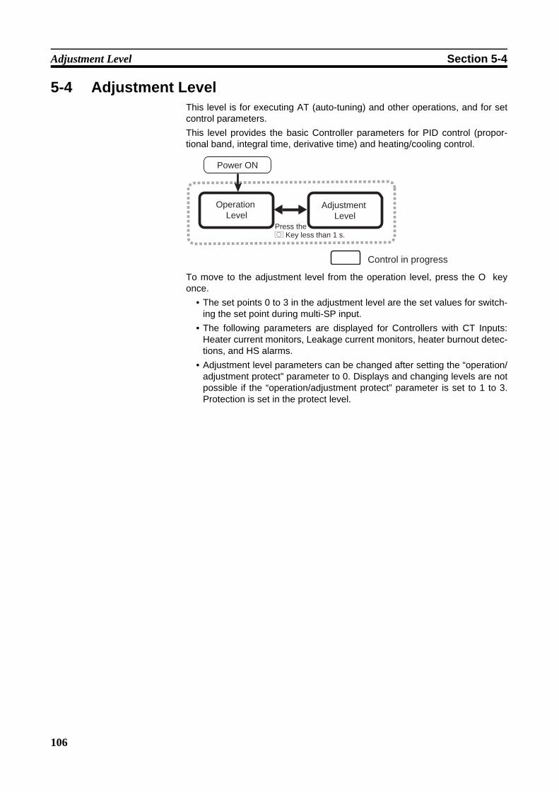
106
Adjustment Level Section 5-4
5-4 Adjustment LevelThis level is for executing AT (auto-tuning) and other operations, and for setcontrol parameters.This level provides the basic Controller parameters for PID control (propor-tional band, integral time, derivative time) and heating/cooling control.
To move to the adjustment level from the operation level, press the O keyonce.
• The set points 0 to 3 in the adjustment level are the set values for switch-ing the set point during multi-SP input.
• The following parameters are displayed for Controllers with CT Inputs:Heater current monitors, Leakage current monitors, heater burnout detec-tions, and HS alarms.
• Adjustment level parameters can be changed after setting the “operation/adjustment protect” parameter to 0. Displays and changing levels are notpossible if the “operation/adjustment protect” parameter is set to 1 to 3.Protection is set in the protect level.
Control in progress
Operation Level
Adjustment Level
Power ON
Press the O Key less than 1 s.
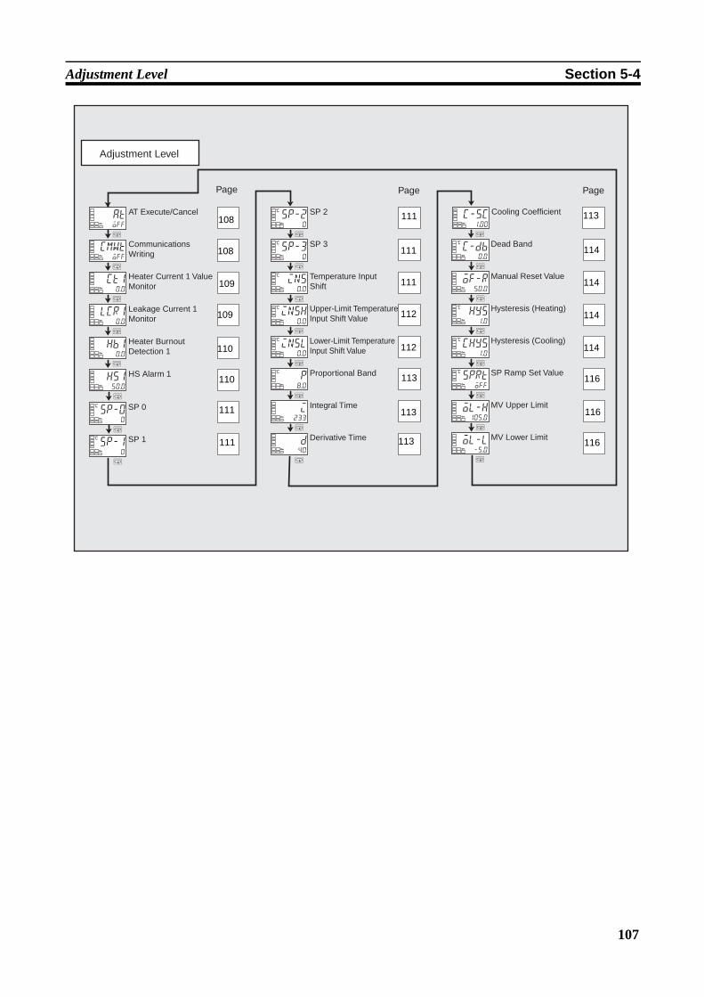
107
Adjustment Level Section 5-4
Adjustment Level
M
M
M
M
M
M
M
M
M
M M
M
M
M
M
M
M
M
M
sp-00
C
sp-10
C
sp-20
C
sp-30
C
ins0.0
C
insh0.0
C
insl0.0
C
p8.0
C
i233
d40
c-sc1.00
c-db0.0
C
of-r50.0
hys1.0
C
chys1.0
C
sprtoff
C
ol-h105.0
ol-l-5.0
Page Page Page
SP 0
SP 1
SP 2
SP 3
Temperature Input Shift
Upper-Limit Temperature Input Shift Value
Lower-Limit Temperature Input Shift Value
Proportional Band
Integral Time
Derivative Time
Cooling Coefficient
Dead Band
Manual Reset Value
Hysteresis (Heating)
Hysteresis (Cooling)
SP Ramp Set Value
MV Upper Limit
MV Lower Limit
M
M
M
M
M
cmwtoff
ct10.0
atoff
lcr10.0
hb10.0
hs150.0
AT Execute/Cancel
Communications Writing
Heater Current 1 Value Monitor
Leakage Current 1 Monitor
Heater Burnout Detection 1
HS Alarm 1
108
108
109
109
110
110
111
111
111
111
111
112
112
113
113
113
113
114
114
114
114
116
116
116

108
Adjustment Level Section 5-4
This parameter executes auto-tuning (AT). • The MV is forcibly increased and decreased around the set point to find
the characteristics of the control object. From the results, the PID con-stants are automatically set in the “proportional band” (P), “integral time”(I), and “derivative time” (D) parameters.
• This parameter is normally off. If you press the U key, the parameter isturned ON and AT is executed. AT cannot be executed when control isstopped or during ON/OFF control.
• When AT execution ends, the parameter setting automatically returns tooff.
Related ParametersProportional band, Integral time, Derivative time (adjustment level): Page 113PID ON/OFF (initial setting level): Page 122
This parameter enables/disables writing of parameters to the E5CZ from thehost (personal computer) using communications.
ON: Writing enabledOFF: Writing disabled
• Default: OFF
Related ParametersMB command logic switching (advanced function setting level): Page 141Communications Unit No., Communications baud rate, Communications datalength, Communications parity, Communications stop bits (communicationssetting level): Page 149
at AT Execute/Cancel The E5CZ must be in operation, and control must be 2-PID control.
Function
Operation
SeeSee
cmwt Communications Writing Communications must be supported.
Function
Setting
SeeSee
■
■

109
Adjustment Level Section 5-4
This parameter measures the heater current from the CT input used fordetecting heater burnout.This parameter measures and displays the heater current value.
• Heater burnouts are not detected if the control output (heating) ON time is190 ms or less.
• ffff is displayed when 55.0 A is exceeded. • If a heater burnout is detected, the HA indicator will light, and the relative
setting level will flash on the No. 1 display.
Related ParametersHeater burnout detection 1 (adjustment level): Page 110HB ON/OFF (advanced function setting level): Page 135Error Displays ct1: Page 158
This parameter measures the heater current from the CT input used fordetecting SSR short-circuits.This parameter measures and displays the heater current when the heater isOFF.
• HS are not detected if the control output (heating) OFF time is 190 ms orless.
• ffff is displayed when 55.0 A is exceeded. • If an SSR short-circuit is detected, the HA indicator will light, and the rela-
tive setting level will flash on the No. 1 display.
Related ParametersHS alarm 1 (adjustment level): Page 110HS alarm use (advanced function setting level): Page 143Error Displays lcr1: Page 158
ct1 Heater Current 1 Value Monitor
Heater burnout and HS alarms must be supported. Alarm 1 must be assigned. The “heater burnout detection” parameter must be set to ON.
Monitor range Unit0.0 to 55.0 A
Function
Monitor
SeeSee
lcr1 Leakage Current 1 Monitor
Heater burnout and HS alarms must be supported. Alarm 1 must be assigned. The “HS alarm” parameter must be set to ON.
Monitor range Unit0.0 to 55.0 A
Function
Monitor
SeeSee
■
■
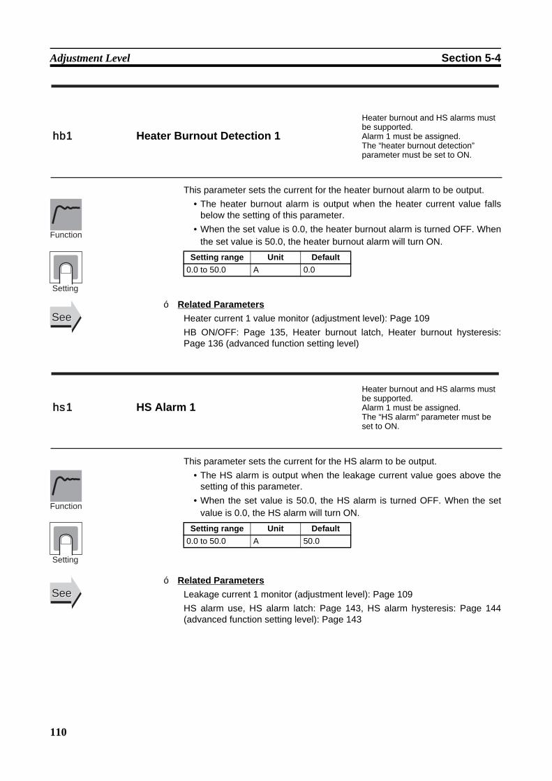
110
Adjustment Level Section 5-4
This parameter sets the current for the heater burnout alarm to be output.• The heater burnout alarm is output when the heater current value falls
below the setting of this parameter.• When the set value is 0.0, the heater burnout alarm is turned OFF. When
the set value is 50.0, the heater burnout alarm will turn ON.
Related ParametersHeater current 1 value monitor (adjustment level): Page 109HB ON/OFF: Page 135, Heater burnout latch, Heater burnout hysteresis:Page 136 (advanced function setting level)
This parameter sets the current for the HS alarm to be output.• The HS alarm is output when the leakage current value goes above the
setting of this parameter.• When the set value is 50.0, the HS alarm is turned OFF. When the set
value is 0.0, the HS alarm will turn ON.
Related ParametersLeakage current 1 monitor (adjustment level): Page 109HS alarm use, HS alarm latch: Page 143, HS alarm hysteresis: Page 144(advanced function setting level): Page 143
hb1 Heater Burnout Detection 1
Heater burnout and HS alarms must be supported. Alarm 1 must be assigned. The “heater burnout detection” parameter must be set to ON.
Setting range Unit Default0.0 to 50.0 A 0.0
Function
Setting
SeeSee
hs1 HS Alarm 1
Heater burnout and HS alarms must be supported. Alarm 1 must be assigned. The “HS alarm” parameter must be set to ON.
Setting range Unit Default0.0 to 50.0 A 50.0
Function
Setting
SeeSee
■
■
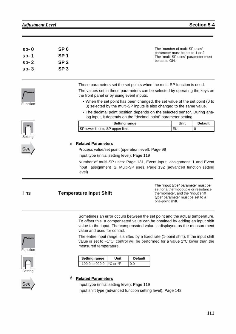
111
Adjustment Level Section 5-4
These parameters set the set points when the multi-SP function is used.The values set in these parameters can be selected by operating the keys onthe front panel or by using event inputs.
• When the set point has been changed, the set value of the set point (0 to3) selected by the multi-SP inputs is also changed to the same value.
• The decimal point position depends on the selected sensor. During ana-log input, it depends on the “decimal point” parameter setting.
Related ParametersProcess value/set point (operation level): Page 99Input type (initial setting level): Page 119
Number of multi-SP uses: Page 131, Event input assignment 1 and Eventinput assignment 2, Multi-SP uses: Page 132 (advanced function settinglevel)
Sometimes an error occurs between the set point and the actual temperature.To offset this, a compensated value can be obtained by adding an input shiftvalue to the input. The compensated value is displayed as the measurementvalue and used for control.The entire input range is shifted by a fixed rate (1-point shift). If the input shiftvalue is set to −1°C, control will be performed for a value 1°C lower than themeasured temperature.
Related ParametersInput type (initial setting level): Page 119Input shift type (advanced function setting level): Page 142
sp-0 SP 0 The “number of multi-SP uses” parameter must be set to 1 or 2. The “multi-SP uses” parameter must be set to ON.
sp-1 SP 1sp-2 SP 2sp-3 SP 3
Setting range Unit DefaultSP lower limit to SP upper limit EU 0
Function
Setting
SeeSee
ins Temperature Input Shift
The “input type” parameter must be set for a thermocouple or resistance thermometer, and the “input shift type” parameter must be set to a one-point shift.
Setting range Unit Default−199.9 to 999.9 °C or °F 0.0
Function
Setting
SeeSee
■
■
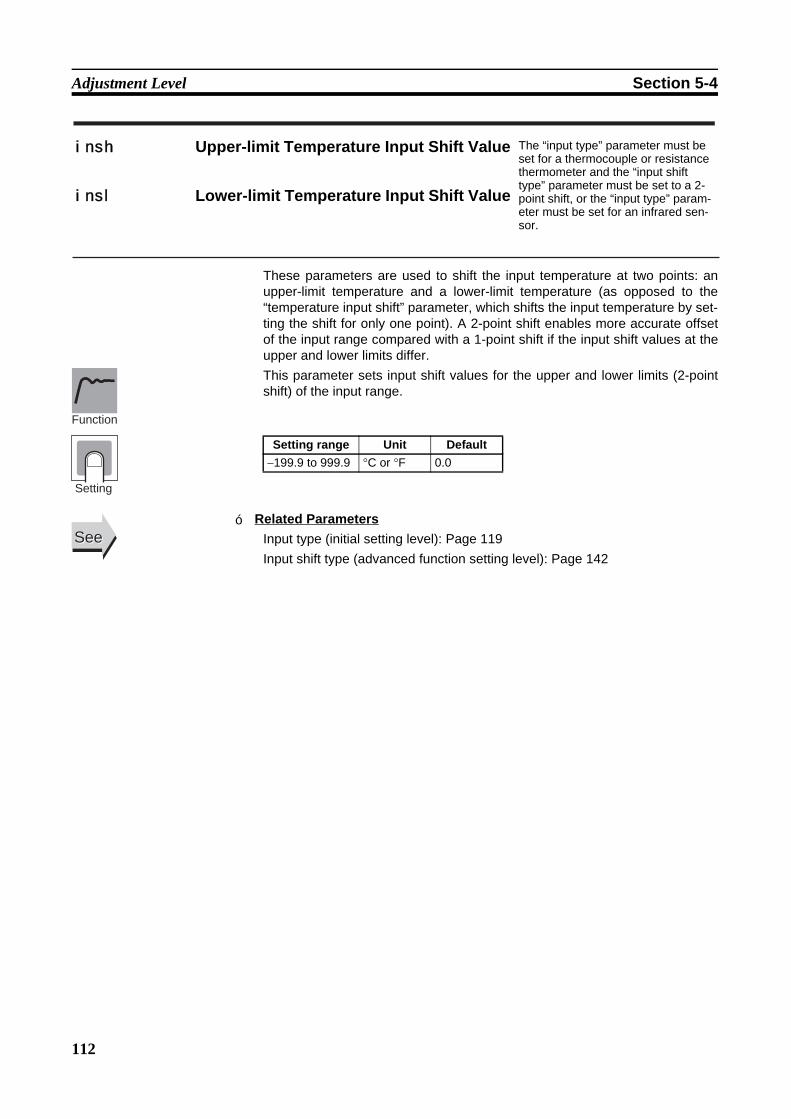
112
Adjustment Level Section 5-4
These parameters are used to shift the input temperature at two points: anupper-limit temperature and a lower-limit temperature (as opposed to the“temperature input shift” parameter, which shifts the input temperature by set-ting the shift for only one point). A 2-point shift enables more accurate offsetof the input range compared with a 1-point shift if the input shift values at theupper and lower limits differ. This parameter sets input shift values for the upper and lower limits (2-pointshift) of the input range.
Related ParametersInput type (initial setting level): Page 119Input shift type (advanced function setting level): Page 142
insh Upper-limit Temperature Input Shift Value The “input type” parameter must be set for a thermocouple or resistance thermometer and the “input shift type” parameter must be set to a 2-point shift, or the “input type” param-eter must be set for an infrared sen-sor.
insl Lower-limit Temperature Input Shift Value
Setting range Unit Default−199.9 to 999.9 °C or °F 0.0
Function
Setting
SeeSee■
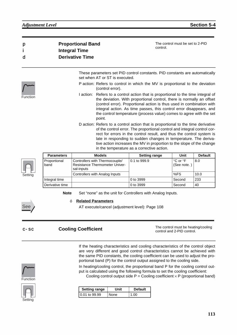
113
Adjustment Level Section 5-4
These parameters set PID control constants. PID constants are automaticallyset when AT or ST is executed.P action: Refers to control in which the MV is proportional to the deviation
(control error).I action: Refers to a control action that is proportional to the time integral of
the deviation. With proportional control, there is normally an offset(control error). Proportional action is thus used in combination withintegral action. As time passes, this control error disappears, andthe control temperature (process value) comes to agree with the setpoint.
D action: Refers to a control action that is proportional to the time derivativeof the control error. The proportional control and integral control cor-rect for errors in the control result, and thus the control system islate in responding to sudden changes in temperature. The deriva-tive action increases the MV in proportion to the slope of the changein the temperature as a corrective action.
Note Set “none” as the unit for Controllers with Analog Inputs.
Related ParametersAT execute/cancel (adjustment level): Page 108
If the heating characteristics and cooling characteristics of the control objectare very different and good control characteristics cannot be achieved withthe same PID constants, the cooling coefficient can be used to adjust the pro-portional band (P) for the control output assigned to the cooling side. In heating/cooling control, the proportional band P for the cooling control out-put is calculated using the following formula to set the cooling coefficient:
Cooling control output side P = Cooling coefficient × P (proportional band)
p Proportional Band The control must be set to 2-PID control.
i Integral Timed Derivative Time
Function
Setting
Parameters Models Setting range Unit DefaultProportional band
Controllers with Thermocouple/Resistance Thermometer Univer-sal-inputs
0.1 to 999.9 °C or °F (See note. )
8.0
Controllers with Analog Inputs %FS 10.0Integral time 0 to 3999 Second 233Derivative time 0 to 3999 Second 40
SeeSee
c-sc Cooling Coefficient The control must be heating/cooling control and 2-PID control.
Setting range Unit Default0.01 to 99.99 None 1.00
Function
Setting
■
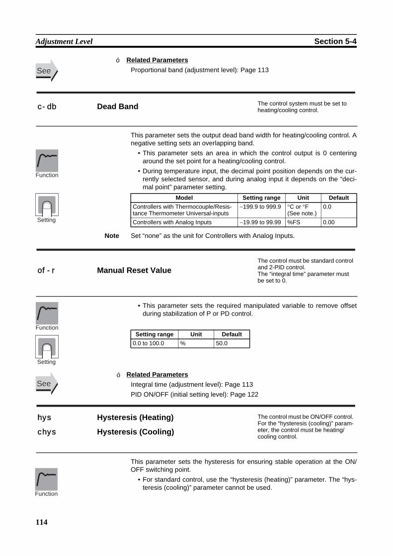
114
Adjustment Level Section 5-4
Related ParametersProportional band (adjustment level): Page 113
This parameter sets the output dead band width for heating/cooling control. Anegative setting sets an overlapping band.
• This parameter sets an area in which the control output is 0 centeringaround the set point for a heating/cooling control.
• During temperature input, the decimal point position depends on the cur-rently selected sensor, and during analog input it depends on the “deci-mal point” parameter setting.
Note Set “none” as the unit for Controllers with Analog Inputs.
• This parameter sets the required manipulated variable to remove offsetduring stabilization of P or PD control.
Related ParametersIntegral time (adjustment level): Page 113PID ON/OFF (initial setting level): Page 122
This parameter sets the hysteresis for ensuring stable operation at the ON/OFF switching point.
• For standard control, use the “hysteresis (heating)” parameter. The “hys-teresis (cooling)” parameter cannot be used.
SeeSee
c-db Dead Band The control system must be set to heating/cooling control.
Model Setting range Unit DefaultControllers with Thermocouple/Resis-tance Thermometer Universal-inputs
−199.9 to 999.9 °C or °F (See note.)
0.0
Controllers with Analog Inputs −19.99 to 99.99 %FS 0.00
Function
Setting
of-r Manual Reset ValueThe control must be standard control and 2-PID control.The “integral time” parameter must be set to 0.
Setting range Unit Default0.0 to 100.0 % 50.0
Function
Setting
SeeSee
hys Hysteresis (Heating) The control must be ON/OFF control. For the “hysteresis (cooling)” param-eter, the control must be heating/cooling control.
chys Hysteresis (Cooling)
Function
■
■
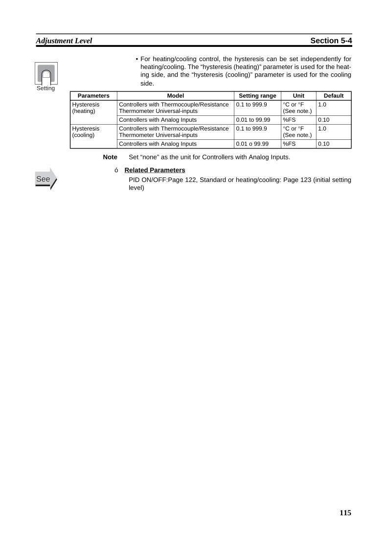
115
Adjustment Level Section 5-4
• For heating/cooling control, the hysteresis can be set independently forheating/cooling. The “hysteresis (heating)” parameter is used for the heat-ing side, and the “hysteresis (cooling)” parameter is used for the coolingside.
Note Set “none” as the unit for Controllers with Analog Inputs.
Related ParametersPID ON/OFF:Page 122, Standard or heating/cooling: Page 123 (initial settinglevel)
Parameters Model Setting range Unit DefaultHysteresis (heating)
Controllers with Thermocouple/Resistance Thermometer Universal-inputs
0.1 to 999.9 °C or °F (See note.)
1.0
Controllers with Analog Inputs 0.01 to 99.99 %FS 0.10Hysteresis (cooling)
Controllers with Thermocouple/Resistance Thermometer Universal-inputs
0.1 to 999.9 °C or °F (See note.)
1.0
Controllers with Analog Inputs 0.01 o 99.99 %FS 0.10
SeeSee■
Setting
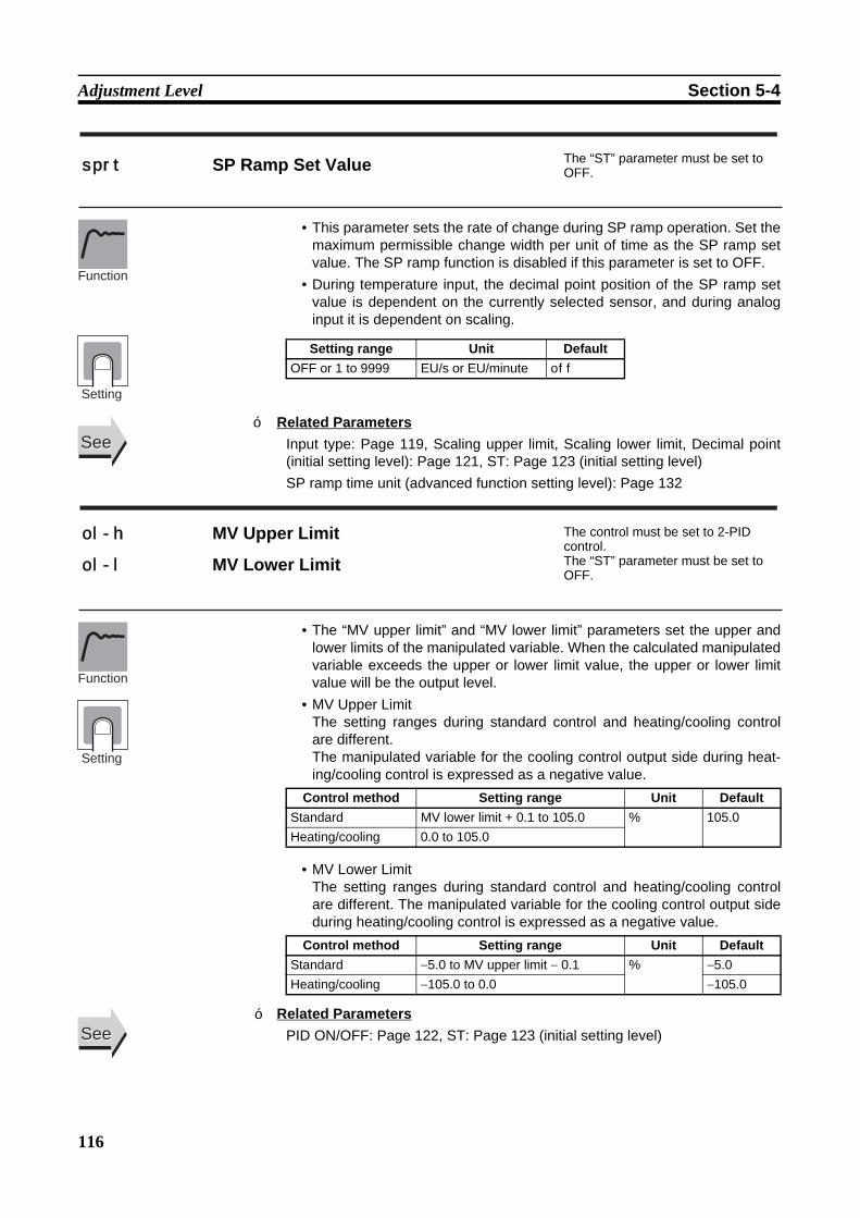
116
Adjustment Level Section 5-4
• This parameter sets the rate of change during SP ramp operation. Set themaximum permissible change width per unit of time as the SP ramp setvalue. The SP ramp function is disabled if this parameter is set to OFF.
• During temperature input, the decimal point position of the SP ramp setvalue is dependent on the currently selected sensor, and during analoginput it is dependent on scaling.
Related ParametersInput type: Page 119, Scaling upper limit, Scaling lower limit, Decimal point(initial setting level): Page 121, ST: Page 123 (initial setting level) SP ramp time unit (advanced function setting level): Page 132
• The “MV upper limit” and “MV lower limit” parameters set the upper andlower limits of the manipulated variable. When the calculated manipulatedvariable exceeds the upper or lower limit value, the upper or lower limitvalue will be the output level.
• MV Upper LimitThe setting ranges during standard control and heating/cooling controlare different. The manipulated variable for the cooling control output side during heat-ing/cooling control is expressed as a negative value.
• MV Lower LimitThe setting ranges during standard control and heating/cooling controlare different. The manipulated variable for the cooling control output sideduring heating/cooling control is expressed as a negative value.
Related ParametersPID ON/OFF: Page 122, ST: Page 123 (initial setting level)
sprt SP Ramp Set Value The “ST” parameter must be set to OFF.
Setting range Unit DefaultOFF or 1 to 9999 EU/s or EU/minute off
Function
Setting
SeeSee
ol-h MV Upper Limit The control must be set to 2-PID control. The “ST” parameter must be set to OFF.
ol-l MV Lower Limit
Control method Setting range Unit DefaultStandard MV lower limit + 0.1 to 105.0 % 105.0Heating/cooling 0.0 to 105.0
Control method Setting range Unit DefaultStandard −5.0 to MV upper limit − 0.1 % −5.0Heating/cooling −105.0 to 0.0 −105.0
Function
Setting
SeeSee
■
■

117
Manual Control Level Section 5-5
5-5 Manual Control LevelThe manipulated variable can be set in manual mode if the “PV/MV” parame-ter is displayed. The final MV used in automatic mode will be used as the initial manual MVwhen moving from automatic mode to manual mode. In manual mode, thechange value will be fixed immediately and reflected in the actual MV.
To move from the operation level to the manual control level, press the O keyfor at least three seconds with the “auto/manual switch” parameter displayed.
• The MANU indicator will light during manual control.• It is not possible to move to any displays except for the “PV/MV” parame-
ter during manual operation.• To return to the operation level, press the O key in the manual control
level for at least one second.
The process value is displayed on the No. 1 display, and the manipulatedvariable (manual MV) is displayed on the No. 2 display.
Related ParametersStandard or heating/cooling (initial setting level): Page 123
a-m
Power ON
Operation Level
Press the O Key for at least 3 s.
Manual Control Level
Press the O Key for at least 1 s.
Press the O Key for at least 1 s; display will flash.
PV/MV (Manual MV)
Monitor range UnitProcess value Input indication range (See page 172.) EU
Setting range UnitMV (manual MV) Standard control −5.0 to 105.0 %
Heating/cooling control −105.0 to 105.0
Function
SeeSee■
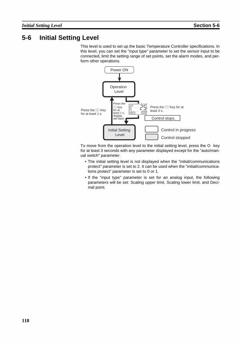
118
Initial Setting Level Section 5-6
5-6 Initial Setting LevelThis level is used to set up the basic Temperature Controller specifications. Inthis level, you can set the “input type” parameter to set the sensor input to beconnected, limit the setting range of set points, set the alarm modes, and per-form other operations.
To move from the operation level to the initial setting level, press the O keyfor at least 3 seconds with any parameter displayed except for the “auto/man-ual switch” parameter.
• The initial setting level is not displayed when the “initial/communicationsprotect” parameter is set to 2. It can be used when the “initial/communica-tions protect” parameter is set to 0 or 1.
• If the “input type” parameter is set for an analog input, the followingparameters will be set: Scaling upper limit, Scaling lower limit, and Deci-mal point.
Operation Level
Initial Setting Level
Control stops.
Power ON
Control in progress
Control stopped
25100
C
Press the O Key for at least 1 s.
Press the O Key for at least 1 s; display will flash.
Press the O Key for at least 3 s.
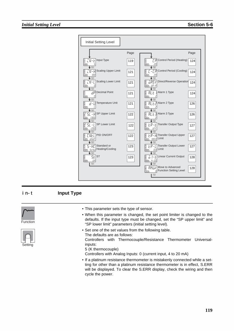
119
Initial Setting Level Section 5-6
• This parameter sets the type of sensor.• When this parameter is changed, the set point limiter is changed to the
defaults. If the input type must be changed, set the “SP upper limit” and“SP lower limit” parameters (initial setting level).
• Set one of the set values from the following table. The defaults are as follows:Controllers with Thermocouple/Resistance Thermometer Universal-inputs: 5 (K thermocouple)Controllers with Analog Inputs: 0 (current input, 4 to 20 mA)
• If a platinum resistance thermometer is mistakenly connected while a set-ting for other than a platinum resistance thermometer is in effect, S.ERRwill be displayed. To clear the S.ERR display, check the wiring and thencycle the power.
Initial Setting Level
M
M
M
M
M
M
M
M
M
M
M
M
M
M
M
M
M
M
M
M
M
in-l0
dp0
in-t5
in-h100
d-uc
sl-h1300
C
sl-l-200
C
cntlonof
s-hcstnd
ston
cp20
c-cp20
oreVor-r
alt12
alt22
alt32
tr-toff
tr-h100.0
tr-l0.0
o1-t4-20
amov0
Page Page
Input Type
Scaling Upper Limit
Scaling Lower Limit
Decimal Point
Temperature Unit
SP Upper Limit
SP Lower Limit
PID ON/OFF
ST
Control Period (Heating)
Control Period (Cooling)
Direct/Reverse Operation
Alarm 1 Type
Alarm 2 Type
Alarm 3 Type
Transfer Output Type
Transfer Output Upper Limit
Transfer Output Lower Limit
Linear Current Output
Move to Advanced Function Setting Level
Standard or Heating/Cooling
119
121
121
121
121
122
122
122
123
123
124
124
124
124
126
126
127
127
127
128
128
in-t Input Type
Function
Setting
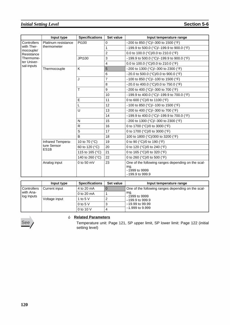
120
Initial Setting Level Section 5-6
Related ParametersTemperature unit: Page 121, SP upper limit, SP lower limit: Page 122 (initialsetting level)
Input type Specifications Set value Input temperature rangeControllers with Ther-mocouple/Resistance Thermome-ter Univer-sal-inputs
Platinum resistance thermometer
Pt100 0 −200 to 850 (°C)/−300 to 1500 (°F)1 −199.9 to 500.0 (°C)/−199.9 to 900.0 (°F)2 0.0 to 100.0 (°C)/0.0 to 210.0 (°F)
JPt100 3 −199.9 to 500.0 (°C)/−199.9 to 900.0 (°F)4 0.0 to 100.0 (°C)/0.0 to 210.0 (°F)
Thermocouple K 5 −200 to 1300 (°C)/−300 to 2300 (°F)6 −20.0 to 500.0 (°C)/0.0 to 900.0 (°F)
J 7 −100 to 850 (°C)/−100 to 1500 (°F)8 −20.0 to 400.0 (°C)/0.0 to 750.0 (°F)
T 9 −200 to 400 (°C)/−300 to 700 (°F)10 −199.9 to 400.0 (°C)/−199.9 to 700.0 (°F)
E 11 0 to 600 (°C)/0 to 1100 (°F)L 12 −100 to 850 (°C)/−100 to 1500 (°F)U 13 −200 to 400 (°C)/−300 to 700 (°F)
14 −199.9 to 400.0 (°C)/−199.9 to 700.0 (°F)N 15 −200 to 1300 (°C)/−300 to 2300 (°F)R 16 0 to 1700 (°C)/0 to 3000 (°F)S 17 0 to 1700 (°C)/0 to 3000 (°F)B 18 100 to 1800 (°C)/300 to 3200 (°F)
Infrared Tempera-ture SensorES1B
10 to 70 (°C) 19 0 to 90 (°C)/0 to 190 (°F)60 to 120 (°C) 20 0 to 120 (°C)/0 to 240 (°F)115 to 165 (°C) 21 0 to 165 (°C)/0 to 320 (°F)140 to 260 (°C) 22 0 to 260 (°C)/0 to 500 (°F)
Analog input 0 to 50 mV 23 One of the following ranges depending on the scal-ing.−1999 to 9999−199.9 to 999.9
Input type Specifications Set value Input temperature rangeControllers with Ana-log Inputs
Current input 4 to 20 mA 0 One of the following ranges depending on the scal-ing.−1999 to 9999−199.9 to 999.9−19.99 to 99.99−1.999 to 9.999
0 to 20 mA 1Voltage input 1 to 5 V 2
0 to 5 V 30 to 10 V 4
SeeSee■

121
Initial Setting Level Section 5-6
• These parameters can be used when the input type is set for an analoginput.
• When an analog input is used, scaling is performed. Set the upper limit inthe “scaling upper limit” parameter and the lower limit in the “scaling lowerlimit” parameter.
• The “decimal point” parameter specifies the decimal point position ofparameters (set point, etc.) whose unit is EU.
• Scaling Upper Limit, Scaling Lower Limit
• Decimal Point
Related ParametersInput type (initial setting level): Page 119
• Set the temperature input unit to either °C or °F.
Related ParametersInput type (initial setting level): Page 119
in-h Scaling Upper Limit The input type must be set for an analog input.
in-l Scaling Lower limitdp Decimal Point
Parameters Setting range Unit DefaultScaling upper limit Scaling lower limit + 1 to 9999 None 100Scaling lower limit −1999 to scaling upper limit − 1 None 0
Parameters Model Setting range
Default
Decimal Point Controllers with Thermocouple/Resis-tance Thermometer Universal-inputs
0 to 1 0
Controllers with Analog Inputs 0 to 3 0
Set value Settings Example0 0 digits past decimal point 12341 1 digits past decimal point 123.42 2 digits past decimal point 12.343 3 digits past decimal point 1.234
Function
Setting
SeeSee
d-u Temperature Unit The input type must be set for a tem-perature input.
Setting range Defaultc: °C, f: °F c
Function
Setting
SeeSee
■
■
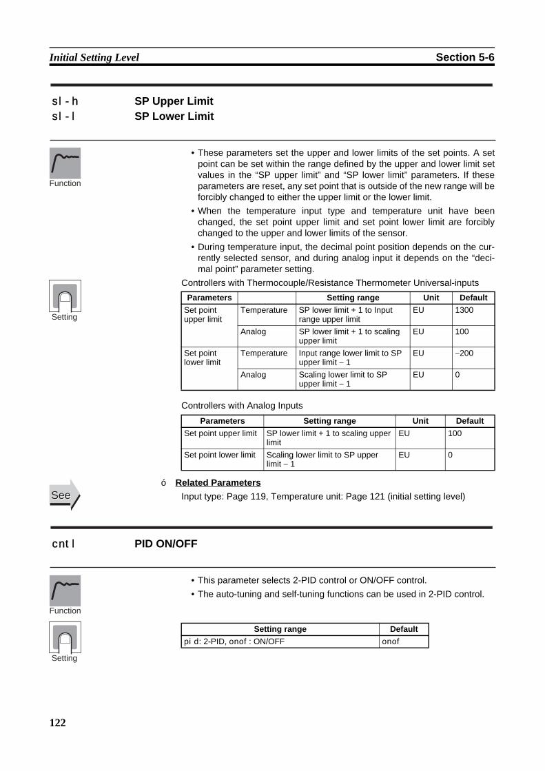
122
Initial Setting Level Section 5-6
• These parameters set the upper and lower limits of the set points. A setpoint can be set within the range defined by the upper and lower limit setvalues in the “SP upper limit” and “SP lower limit” parameters. If theseparameters are reset, any set point that is outside of the new range will beforcibly changed to either the upper limit or the lower limit.
• When the temperature input type and temperature unit have beenchanged, the set point upper limit and set point lower limit are forciblychanged to the upper and lower limits of the sensor.
• During temperature input, the decimal point position depends on the cur-rently selected sensor, and during analog input it depends on the “deci-mal point” parameter setting.
Controllers with Thermocouple/Resistance Thermometer Universal-inputs
Controllers with Analog Inputs
Related ParametersInput type: Page 119, Temperature unit: Page 121 (initial setting level)
• This parameter selects 2-PID control or ON/OFF control. • The auto-tuning and self-tuning functions can be used in 2-PID control.
sl-h SP Upper Limit sl-l SP Lower Limit
Parameters Setting range Unit DefaultSet point upper limit
Temperature SP lower limit + 1 to Input range upper limit
EU 1300
Analog SP lower limit + 1 to scaling upper limit
EU 100
Set point lower limit
Temperature Input range lower limit to SP upper limit − 1
EU −200
Analog Scaling lower limit to SP upper limit − 1
EU 0
Parameters Setting range Unit DefaultSet point upper limit SP lower limit + 1 to scaling upper
limitEU 100
Set point lower limit Scaling lower limit to SP upper limit − 1
EU 0
Function
Setting
SeeSee
cntl PID ON/OFF
Setting range Defaultpid: 2-PID, onof: ON/OFF onof
Function
Setting
■
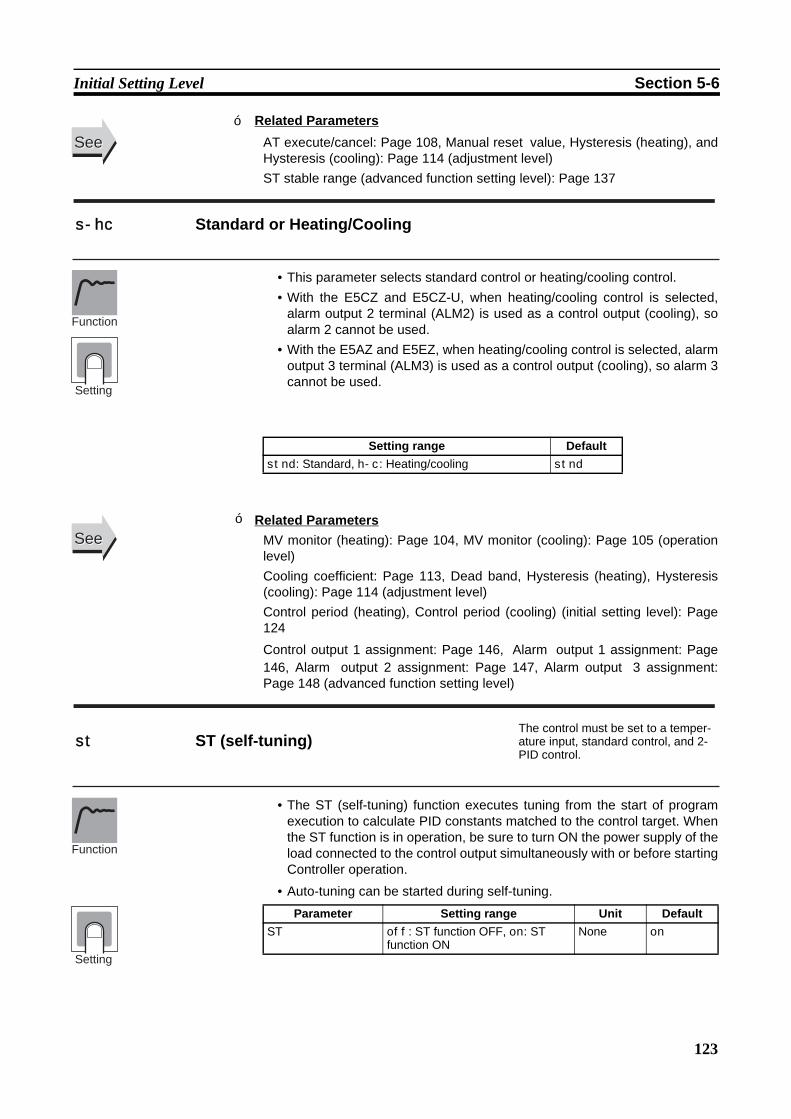
123
Initial Setting Level Section 5-6
Related ParametersAT execute/cancel: Page 108, Manual reset value, Hysteresis (heating), andHysteresis (cooling): Page 114 (adjustment level)ST stable range (advanced function setting level): Page 137
• This parameter selects standard control or heating/cooling control.• With the E5CZ and E5CZ-U, when heating/cooling control is selected,
alarm output 2 terminal (ALM2) is used as a control output (cooling), soalarm 2 cannot be used.
• With the E5AZ and E5EZ, when heating/cooling control is selected, alarmoutput 3 terminal (ALM3) is used as a control output (cooling), so alarm 3cannot be used.
Related ParametersMV monitor (heating): Page 104, MV monitor (cooling): Page 105 (operationlevel)Cooling coefficient: Page 113, Dead band, Hysteresis (heating), Hysteresis(cooling): Page 114 (adjustment level)Control period (heating), Control period (cooling) (initial setting level): Page124
Control output 1 assignment: Page 146, Alarm output 1 assignment: Page146, Alarm output 2 assignment: Page 147, Alarm output 3 assignment:Page 148 (advanced function setting level)
• The ST (self-tuning) function executes tuning from the start of programexecution to calculate PID constants matched to the control target. Whenthe ST function is in operation, be sure to turn ON the power supply of theload connected to the control output simultaneously with or before startingController operation.
• Auto-tuning can be started during self-tuning.
SeeSee
s-hc Standard or Heating/Cooling
Setting range Defaultstnd: Standard, h-c: Heating/cooling stnd
Function
Setting
SeeSee
st ST (self-tuning)The control must be set to a temper-ature input, standard control, and 2-PID control.
Parameter Setting range Unit DefaultST off: ST function OFF, on: ST
function ONNone on
Function
Setting
■
■
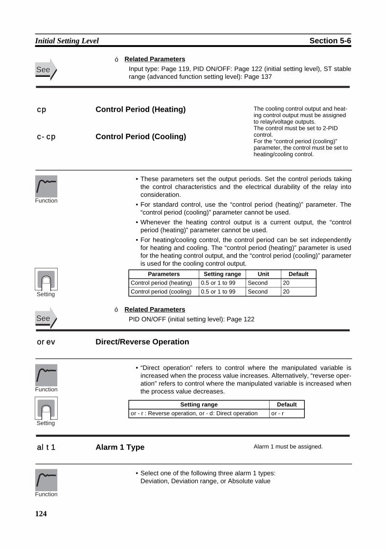
124
Initial Setting Level Section 5-6
Related ParametersInput type: Page 119, PID ON/OFF: Page 122 (initial setting level), ST stablerange (advanced function setting level): Page 137
• These parameters set the output periods. Set the control periods takingthe control characteristics and the electrical durability of the relay intoconsideration.
• For standard control, use the “control period (heating)” parameter. The“control period (cooling)” parameter cannot be used.
• Whenever the heating control output is a current output, the “controlperiod (heating)” parameter cannot be used.
• For heating/cooling control, the control period can be set independentlyfor heating and cooling. The “control period (heating)” parameter is usedfor the heating control output, and the “control period (cooling)” parameteris used for the cooling control output.
Related ParametersPID ON/OFF (initial setting level): Page 122
• “Direct operation” refers to control where the manipulated variable isincreased when the process value increases. Alternatively, “reverse oper-ation” refers to control where the manipulated variable is increased whenthe process value decreases.
• Select one of the following three alarm 1 types:Deviation, Deviation range, or Absolute value
SeeSee
cp Control Period (Heating) The cooling control output and heat-ing control output must be assigned to relay/voltage outputs. The control must be set to 2-PID control. For the “control period (cooling)” parameter, the control must be set to heating/cooling control.
c-cp Control Period (Cooling)
Parameters Setting range Unit DefaultControl period (heating) 0.5 or 1 to 99 Second 20Control period (cooling) 0.5 or 1 to 99 Second 20
Function
Setting
SeeSee
orev Direct/Reverse Operation
Setting range Defaultor-r: Reverse operation, or-d: Direct operation or-r
Function
Setting
alt1 Alarm 1 Type Alarm 1 must be assigned.
Function
■
■
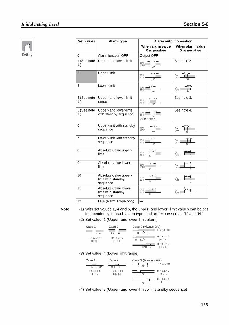
125
Initial Setting Level Section 5-6
Note (1) With set values 1, 4 and 5, the upper- and lower- limit values can be setindependently for each alarm type, and are expressed as “L” and “H.”
(2) Set value: 1 (Upper- and lower-limit alarm)
(3) Set value: 4 (Lower limit range)
(4) Set value: 5 (Upper- and lower-limit with standby sequence)
Set values Alarm type Alarm output operationWhen alarm value
X is positiveWhen alarm value
X is negative0 Alarm function OFF Output OFF1 (See note 1.)
Upper- and lower-limit See note 2.
2 Upper-limit
3 Lower-limit
4 (See note 1.)
Upper- and lower-limit range
See note 3.
5 (See note 1.)
Upper- and lower-limit with standby sequence
See note 4.
6 Upper-limit with standby sequence
7 Lower-limit with standby sequence
8 Absolute-value upper-limit
9 Absolute-value lower-limit
10 Absolute-value upper-limit with standby sequence
11 Absolute-value lower-limit with standby sequence
12 LBA (alarm 1 type only) ---
L HONOFF
SP
XONOFF
SP
ONOFF
SP
X
XONOFF
SP
XONOFF
SP
L HONOFF
SP
L HONOFF
SPSee note 5.
XONOFF
SP
ONOFF
SP
X
XONOFF
SP
XONOFF
SP
XONOFF
0
XONOFF
0
ONOFF
X
0
ONOFF
X
0
XONOFF
0
XONOFF
0
ONOFF
X
0
ONOFF
X
0
L H
H < 0, L > 0|H| < |L|
SP L H
H > 0, L < 0|H| > |L|
SP LHH < 0, L < 0
SP
LHH < 0, L > 0
|H| ≥ |L|SP
LHH > 0, L < 0
|H| ≤ |L|SP
Case 3 (Always ON)Case 2Case 1
L H
H < 0, L > 0|H| < |L|
SP HL
H > 0, L < 0|H| > |L|
SP LHH < 0, L < 0
SP
L
L
H
H
H < 0, L > 0|H| ≥ |L|SP
SP
H > 0, L < 0|H| ≤ |L|
Case 3 (Always OFF)Case 2Case 1
Setting

126
Initial Setting Level Section 5-6
• For the lower-limit alarms in cases 1 and 2 above, the alarm is normal-ly OFF if upper- and lower-limit hysteresis overlaps.
• In case 3, the alarm is always OFF.(5) Set value: 5 (The alarm is always OFF if upper- and lower-limit alarm hys-
teresis with standby sequence overlaps.)• Set the alarm type independently for each alarm in the “alarm 1 to 3 type”
parameters in the initial setting level. The default is 2 (Upper-limit alarm).
Related ParametersAlarm value 1: Page 101, Alarm value upper limit 1, Alarm value lower limit 1:Page 103 (operation level)Standby sequence reset: Page 133, Alarm 1 open in alarm: Page 134, Alarm1 hysteresis: Page 135, Alarm 1 latch: Page 139 (advanced function settinglevel)
• Select one of the following three alarm 2 types:Deviation, Deviation range, or Absolute value
Refer to the alarm 1 type list.
Related ParametersAlarm value 2: Page 102, Alarm value upper limit 2, Alarm value lower limit 2:Page 103 (operation level)Standby sequence reset: Page 133, Alarm 2 open in alarm: Page 134, Alarm2 hysteresis: Page 135, Alarm 2 latch: Page 139 (advanced function settinglevel)
• Select one of the following three alarm 3 types:Deviation, Deviation range, or Absolute value
Refer to the alarm 1 type list.
Related ParametersAlarm value 3: Page 102, Alarm value upper limit 3, Alarm value lower limit 3:Page 104 (operation level)
SeeSee
alt2 Alarm 2 Type Alarm 2 must be assigned.
Function
Setting
SeeSee
alt3 Alarm 3 Type Alarm 3 must be assigned.
Function
Setting
SeeSee
■
■
■
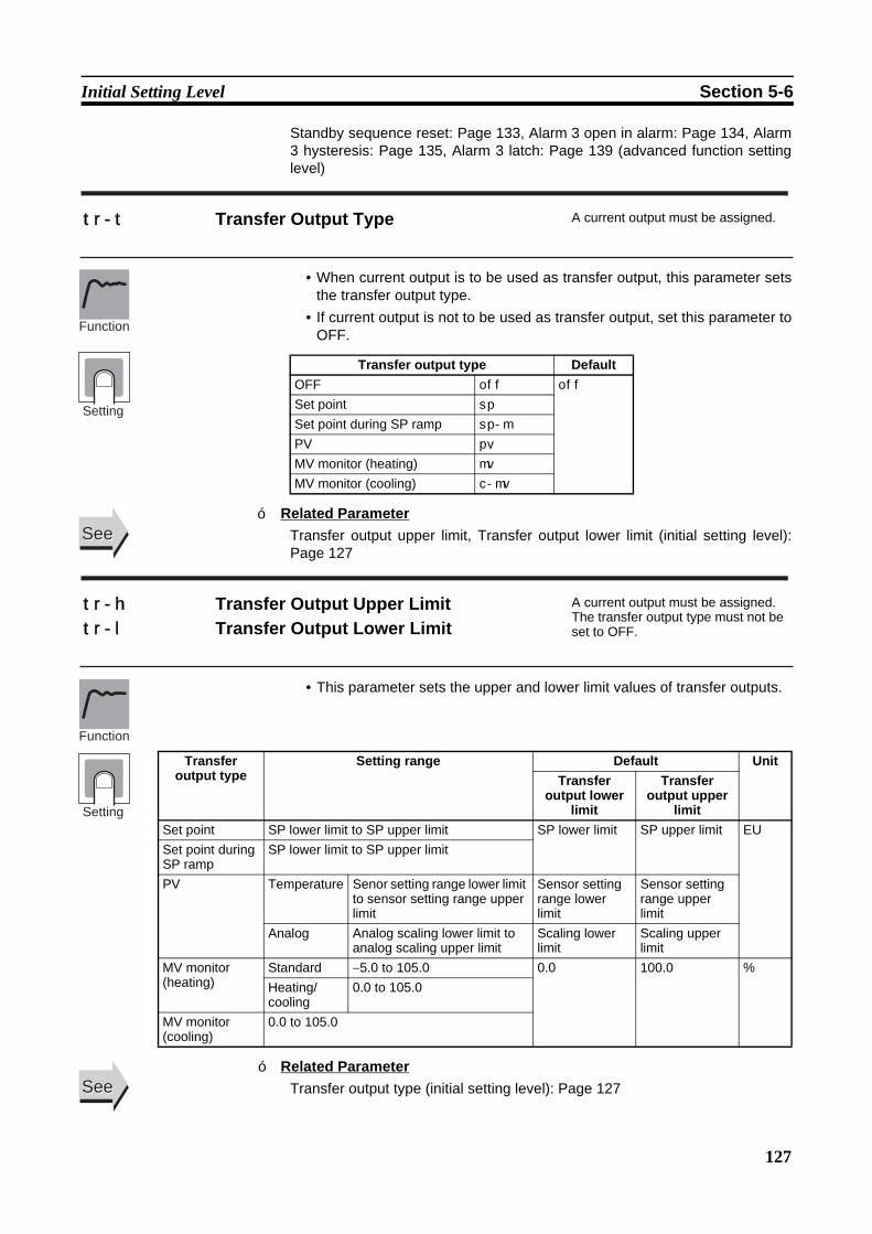
127
Initial Setting Level Section 5-6
Standby sequence reset: Page 133, Alarm 3 open in alarm: Page 134, Alarm3 hysteresis: Page 135, Alarm 3 latch: Page 139 (advanced function settinglevel)
• When current output is to be used as transfer output, this parameter setsthe transfer output type.
• If current output is not to be used as transfer output, set this parameter toOFF.
Related ParameterTransfer output upper limit, Transfer output lower limit (initial setting level):Page 127
• This parameter sets the upper and lower limit values of transfer outputs.
Related ParameterTransfer output type (initial setting level): Page 127
tr-t Transfer Output Type A current output must be assigned.
Transfer output type DefaultOFF off off
Set point sp
Set point during SP ramp sp-m
PV pv
MV monitor (heating) mv
MV monitor (cooling) c-mv
Function
Setting
SeeSee
tr-h Transfer Output Upper Limit A current output must be assigned.The transfer output type must not be set to OFF.tr-l Transfer Output Lower Limit
Function
Setting
Transfer output type
Setting range Default UnitTransfer
output lower limit
Transfer output upper
limitSet point SP lower limit to SP upper limit SP lower limit SP upper limit EUSet point during SP ramp
SP lower limit to SP upper limit
PV Temperature Senor setting range lower limit to sensor setting range upper limit
Sensor setting range lower limit
Sensor setting range upper limit
Analog Analog scaling lower limit to analog scaling upper limit
Scaling lower limit
Scaling upper limit
MV monitor (heating)
Standard −5.0 to 105.0 0.0 100.0 %Heating/cooling
0.0 to 105.0
MV monitor (cooling)
0.0 to 105.0
SeeSee
■
■

128
Initial Setting Level Section 5-6
This parameter selects the output type for linear current outputs.
• Select either 4 to 20 mA or 0 to 20 mA when control output 1 is a currentoutput.
Note Even when control output 1 is used as a control output or a simple transferoutput, 0 to 20 mA can be used.
Related ParameterTransfer output type (initial setting level): Page 127
• Set the “move to advanced setting level” parameter set value to “−169.”• Move to the advanced setting level either by pressing the M key or O
key or by waiting for 2 seconds to elapse.
Related ParameterInitial setting/communications protect (protect level): Page 96
o1-t Linear Current Output A current output must be assigned.
Linear current output
Default
4-20: 4 to 20 mA 0-20: 0 to 20 mA
4-20
Function
Setting
SeeSee
amov Move to Advanced Function Setting Level The “initial setting/communications protect” parameter must be set to 0.
Function
SeeSee
■
■
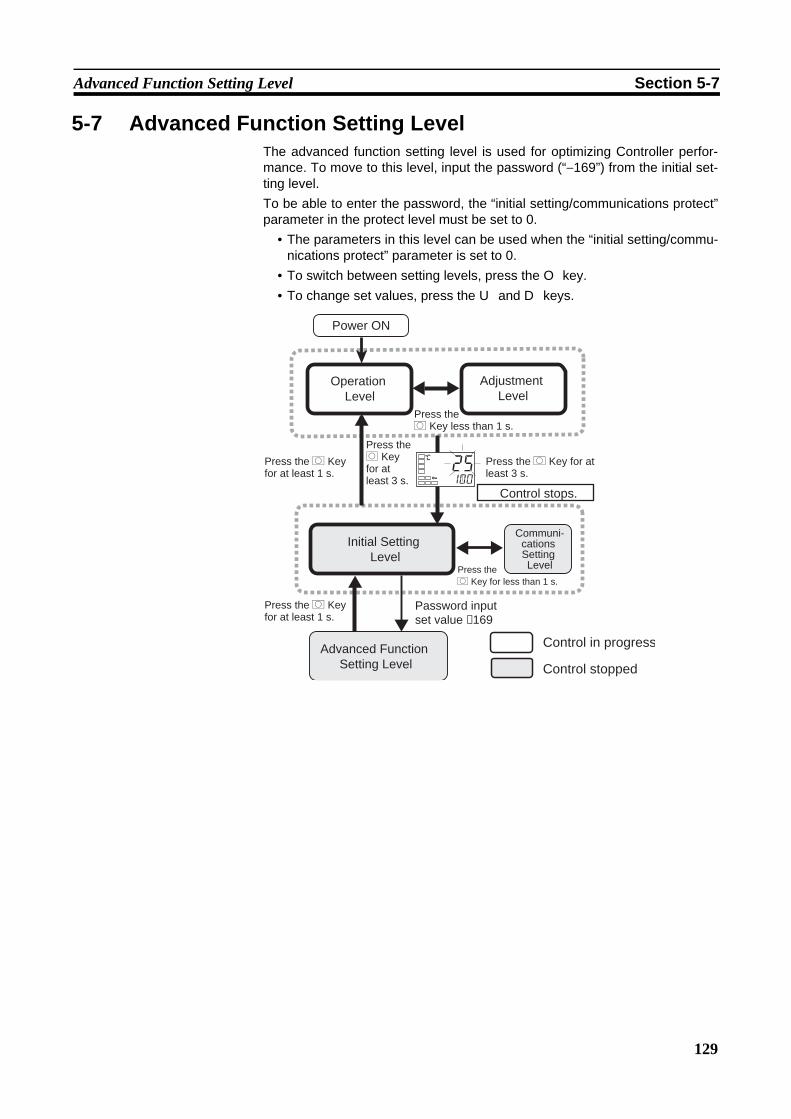
129
Advanced Function Setting Level Section 5-7
5-7 Advanced Function Setting LevelThe advanced function setting level is used for optimizing Controller perfor-mance. To move to this level, input the password (“−169”) from the initial set-ting level.To be able to enter the password, the “initial setting/communications protect”parameter in the protect level must be set to 0.
• The parameters in this level can be used when the “initial setting/commu-nications protect” parameter is set to 0.
• To switch between setting levels, press the O key.• To change set values, press the U and D keys.
Password inputset value −169
Control in progress
Control stopped
Operation Level
Initial Setting Level
Control stops.
Communi- cations Setting Level
Adjustment Level
Power ON
Advanced Function Setting Level
25100
CPress the O Key for at least 1 s.
Press the O Key less than 1 s.
Press the O Key for at least 3 s.
Press the O Key for at least 3 s.
Press the O Key for less than 1 s.
Press the O Key for at least 1 s.

130
Advanced Function Setting Level Section 5-7
• This parameter returns all parameter settings to their defaults.• After the initialization, the set value automatically turns off.
init Parameter Initialization
Advanced Function Setting Level
M
M
M
M
M
M
M
M
M
M
M
M
M
M
M
M
M
M
M
M
M
M
M
M
M
M
M
M
M
M
M
M
M
M
M
M
M
M
M
M
M
M
M
M
M
M
alm3alm3
Alarm Output 3 Assignment
initoff
ev-m1
ev-1none
ev-2stop
mspuoff
sprum
resta
al1nn-o
alh10.2
C
al2nn-o
alh20.2
C
al3nn-o
alh30.2
C
hbuon
hbloff
hbh0.1
st-b15.0
C
alfa0.65
inf0.0
pvadoff
o-dpoff
retoff
a1ltoff
a2ltoff
a3ltoff
prlt3
serooff
cjcon
rlrvoff
a1on0
a2on0
a3on0
a1of0
a2of0
a3of0
istpins1
amadoff
hsuon
hsloff
hsh0.1
lba0
lbal8.0
C
lbab3.0
C
out1o
alm1alm1
alm2alm2
cselon
Page Page Page Page
Parameter Initialization
Number of Multi-SP Uses
Event Input Assignment 1
Event Input Assignment 2
Multi-SP Uses
SP Ramp Time Unit
Standby Sequence Reset
Alarm 1 Open In Alarm
Alarm 1 Hysteresis
Alarm 2 Open In Alarm
Alarm 2 Hysteresis
Alarm 3 Open In Alarm
Alarm 3 Hysteresis
Heater Burnout Latch
Heater Burnout Hysteresis
ST Stable Range
α
Input Digital Filter
Additional PV Display
MV Display
Automatic DisplayReturn Time
Alarm 1 Latch
Alarm 2 Latch
Alarm 3 Latch
Input Error Output
Cold Junction Compensation Method
MB Command Logic Switching
Alarm 1 ON Delay
Alarm 2 ON Delay
Alarm 3 ON Delay
Alarm 1 OFF Delay
Alarm 2 OFF Delay
Alarm 3 OFF Delay
Input Shift Type
Auto/Manual Select Addition
HS Alarm Use
HS Alarm Latch
HS Alarm Hysteresis
LBA Detection Time
LBA Level
LBA Band
Control Output 1 Assignment
Alarm Output 1 Assignment
Alarm Output 2 Assignment
CharacterSelect
HB ON/OFF Move to Protect Level time
130
131
132
132
132
132
133
134
134
134
135
135
135
135
136
136
137
137
138
138
138
139
139
139
139
140
140
140
141
141
141
141
142
142
142
142
143
143
143
144
144
145
145
146
146
147
148
148
Setting range Defaultoff: Initialization is not executed. off
fact: Initializes to the factory settings described in the manual.
Function
Setting

131
Advanced Function Setting Level Section 5-7
Multi-SP is a function for setting set points 0 to 3 in advance, and switchingbetween these set points using the ON/OFF combinations of event inputs 1and 2.The “number of multi-SP uses” parameter is used when the number of presetset points is either two or four.This parameter determines whether the “event input assignment 1” and“event input assignment 2” parameters are displayed.The “number of multi-SP uses” parameter displays which functions areassigned to event inputs 1 and 2.
Note If the “number of multi-SP uses” parameter is set to 0, both input assign-ments 1 and 2 can be set. Once “STOP” (RUN/STOP), or “MANU” (auto/manual) has been assigned to one event input, the other event can beassigned only to either of the remaining two settings.
• Default: 1Multi-SP switching by event inputs can be used with Controllers that haveevent inputs, when the “number of multi-SP uses” parameter is set to 1 or 2.The following tables show the relationships between ON/OFF combinations ofevent inputs 1 and 2 and selected set points.
Number of Multi-SP Uses: 1
Number of Multi-SP Uses: 2
Note Event inputs can be used on the following Controllers. E5CZ-@2M@@ withE53-CZB or E53-CZHB,E5AZ-@3@M@@ with E53-AZB,E5EZ-@3@M@@with E53-AZB.Turn the event inputs ON or OFF while the power is turnedON. Event input ON/OFF changes are detected for inputs of 50 ms or longer.
ev-m Number of Multi-SP Uses Event inputs must be supported.
Settings Event inputsEvent input
assignment 1Event input
assignment 2Function of
event input 1Function of
event input 2Number of multi-SP uses
0 (See note. )
NONE, STOP, MANU None, or switching RUN/STOP, or auto/manual
1 (Not dis-played.)
NONE, STOP, MANU
Multi-SP, 2 points (switch-ing set points 0 and 1)
None, or switching RUN/STOP, or auto/man-ual
2 (Not displayed.) Multi-SP, 4 points (switching set points 0, 1, 2, 3)
Function
Setting
Event input 1 Selected set pointOFF Set point 0ON Set point 1
Event input 1 Event input 2 Selected set pointOFF OFF Set point 0ON OFF Set point 1OFF ON Set point 2ON ON Set point 3

132
Advanced Function Setting Level Section 5-7
Related ParametersSP 0 to SP 3 (adjustment level): Page 111Event input assignment 1, Event input assignment 2, Multi-SP uses: Page132 (advanced function setting level)
• The following functions are assigned for event input 1 and event input 2.RUN/STOPAuto/manual switch
• Defaults:Event input assignment 1: none
Event input assignment 2: stop
Related ParametersSP 0 to SP 3 (adjustment level): Page 111, Number of multi-SP uses (advanced function setting level): Page 131
This parameter enables switching between set points 0 to 3 by operating thekeys on the front panel.Prerequisites
• A model without event inputs• The “number of multi-SP uses” parameter set to 0 on a model with event
inputson: Set points 0 to 3 can be selected.off: Set points 0 to 3 cannot be selected.
• Default : OFF
Related ParametersMulti-SP set point setting (operation level): Page 99Number of multi-SP uses (advanced function setting level): Page 131
• This parameter sets the time unit for the rate of change during SP rampoperation.
SeeSee
ev-1 Event Input Assignment 1 Event inputs must be supported.The “number of multi-SP uses” parameter must be set to 0 or 1.ev-2 Event Input Assignment 2
Settings Functionnone Nonestop RUN/STOPmanu Auto/manual switch
Function
Setting
SeeSee
mspu Multi-SP UsesThe model must not support event inputs, or the number of multi-SP uses must be 0.
Function
Setting
SeeSee
spru SP Ramp Time Unit The “ST” parameter must be set to OFF.
Function
■
■
■
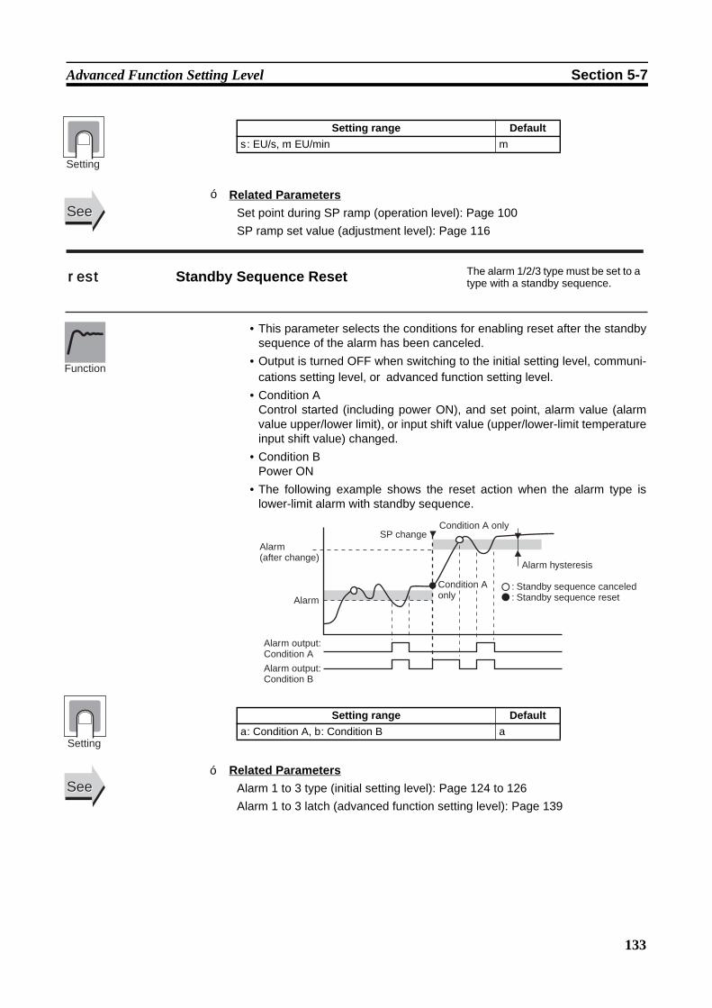
133
Advanced Function Setting Level Section 5-7
Related ParametersSet point during SP ramp (operation level): Page 100SP ramp set value (adjustment level): Page 116
• This parameter selects the conditions for enabling reset after the standbysequence of the alarm has been canceled.
• Output is turned OFF when switching to the initial setting level, communi-cations setting level, or advanced function setting level.
• Condition AControl started (including power ON), and set point, alarm value (alarmvalue upper/lower limit), or input shift value (upper/lower-limit temperatureinput shift value) changed.
• Condition BPower ON
• The following example shows the reset action when the alarm type islower-limit alarm with standby sequence.
Related ParametersAlarm 1 to 3 type (initial setting level): Page 124 to 126Alarm 1 to 3 latch (advanced function setting level): Page 139
Setting range Defaults: EU/s, m: EU/min m
SeeSee
Setting
rest Standby Sequence Reset The alarm 1/2/3 type must be set to a type with a standby sequence.
Setting range Defaulta: Condition A, b: Condition B a
Function
Alarm (after change)
Alarm
SP changeCondition A only
Condition A only
Alarm hysteresis
: Standby sequence canceled: Standby sequence reset
Alarm output: Condition A
Alarm output: Condition B
Setting
SeeSee
■
■

134
Advanced Function Setting Level Section 5-7
• This parameter sets the output status for alarm 1.• When “close in alarm” is set, the status of the alarm output function will be
output as is. When “open in alarm” is set, the status of the alarm outputfunction will be reversed before being output. The following table showsthe relationship between alarm output functions, alarm output and outputLCDs.
• When “open in alarm” is set, the “open in alarm” status is also applied toheater burnout and HS alarm outputs, and to input error outputs.
Related ParametersAlarm value 1: Page 101, Alarm value upper limit 1, Alarm value lower limit 1:Page 103 (operation level)Alarm 1 type (initial setting level): Page 124Standby sequence reset: Page 133, Alarm 1 hysteresis: Page 135, Alarm 1latch: Page 139 (advanced function setting level)
• These parameters set the output status for alarm 2 and alarm 3 settings.• When “close in alarm” is set, the status of the alarm output function will be
output as is. When “open in alarm” is set, the status of the alarm outputfunction will be reversed before being output. The following table showsthe relationship between alarm output functions, alarm output and outputLCDs.
al1n Alarm 1 Open in Alarm Alarm 1 must be assigned.
Alarm output operation Alarm output Output LCDsClose in alarm ON ON Lit
OFF OFF Not litOpen in alarm ON OFF Lit
OFF ON Not lit
Setting range Defaultn-o: Close in alarm, n-c: Open in alarm n-o
Setting
Function
SeeSee
al2n Alarm 2 Open in Alarm Alarm 2 must be assigned.
al3n Alarm 3 Open in Alarm Alarm 3 must be assigned.
Alarm output operation Alarm output Output LCDsClose in alarm ON ON Lit
OFF OFF Not litOpen in alarm ON OFF Lit
OFF ON Not lit
Setting range Defaultn-o: Close in alarm, n-c: Open in alarm n-o
Function
Setting
■

135
Advanced Function Setting Level Section 5-7
Related ParametersAlarm value 2 and 3: Page 102, Alarm value upper limit 2 and 3, Alarm valuelower limit 2 and 3: Page 103 to 104 (operation level)Alarm 2 to 3 type (initial setting level): Page 126Alarm 2 and 3 hysteresis: Page 135, Standby sequence reset: Page 133,Alarm 2 and 3 latch: Page 139 (advanced function setting level)
• These parameters set alarm 1, 2, and 3 hysteresis.
Note Set “none” as the unit for Controllers with Analog Inputs.
Related ParametersAlarm value 1 to 3: Page 101 to 102, Alarm value upper limit 1 to 3: Page 103to 104, Alarm value lower limit 1 to 3: Page 103 to 104 (operation level)Alarm 1 to 3 type (initial setting level): Page 124 to 126 Standby sequence reset: Page 133, Alarm 1 to 3 open in alarm: Page 134,Alarm 1 to 3 latch: Page 139 (advanced function setting level)
• Set to use the heater burnout alarm.
SeeSee
alh1 Alarm 1 Hysteresis Alarm 1 must be assigned, and the alarm 1 type must not be 0 or 12.
alh2 Alarm 2 Hysteresis Alarm 2 must be assigned, and the alarm 2 type must not be 0.
alh3 Alarm 3 Hysteresis Alarm 3 must be assigned, and the alarm 3 type must not be 0.
Models Setting range Unit DefaultControllers with Thermocouple/Resis-tance Thermometer Universal-inputs
0.1 to 999.9 °C or °F (See note.)
0.2
Controllers with Analog Inputs 0.01 to 99.99 %FS 0.02
Function
Setting
SeeSee
hbu HB ON/OFFHeater burnout and HS alarms must be supported.Alarm 1 must be assigned.
Setting range Defaulton: Enabled, off: Disabled on
Function
Setting
■
■
136
Advanced Function Setting Level Section 5-7
• When this parameter is set to ON, the heater burnout alarm is held untileither of the following conditions is satisfied.
a Heater burnout detection is set to 0.0 A.b The power is turned OFF then back ON again (i.e., power is reset).
• Output is turned OFF when switching to the initial setting level, communi-cations setting level, or advanced function setting level.
Related ParameterHB ON/OFF (advanced function setting level): Page 135
• This parameter sets hysteresis for heater burnout detection.
Related ParameterHB ON/OFF (advanced function setting level): Page 135
hbl Heater Burnout Latch
Heater burnout and HS alarms must be supported.Alarm 1 must be assigned.The “heater burnout detection” parameter must be set to ON.
Setting range Defaulton: Enabled, off: Disabled off
Function
Setting
SeeSee
hbh Heater Burnout Hysteresis
The “heater burnout” parameter must be set to ON.The “heater burnout latch” parameter must be set to OFF.Heater burnout and HS alarms must be supported.Alarm 1 must be assigned.
Setting range Unit Default0.1 to 50.0 A 0.1
Function
Setting
SeeSee
■
■
137
Advanced Function Setting Level Section 5-7
• The setting of this parameter determines when ST operates.This parameter cannot be used when ST is set to OFF.
Related ParametersInput type: Page 119, PID ON/OFF: Page 122, ST: Page 123 (initial settinglevel)
• Normally, use the default for this parameter.• This parameter sets the 2-PID control α constant.
Related ParametersPID ON/OFF: Page 122, ST: Page 123 (initial setting level)
st-b ST Stable RangeST must be ON and temperature input, standard control, 2-PID control must be set.
Setting range Unit Default0.1 to 999.9 °C or °F 15.0
Function
Setting
SeeSee
alfa α ST must be OFF and 2-PID control must be set.
Setting range Unit Default0.00 to 1.00 None 0.65
Function
Setting
SeeSee
■
■
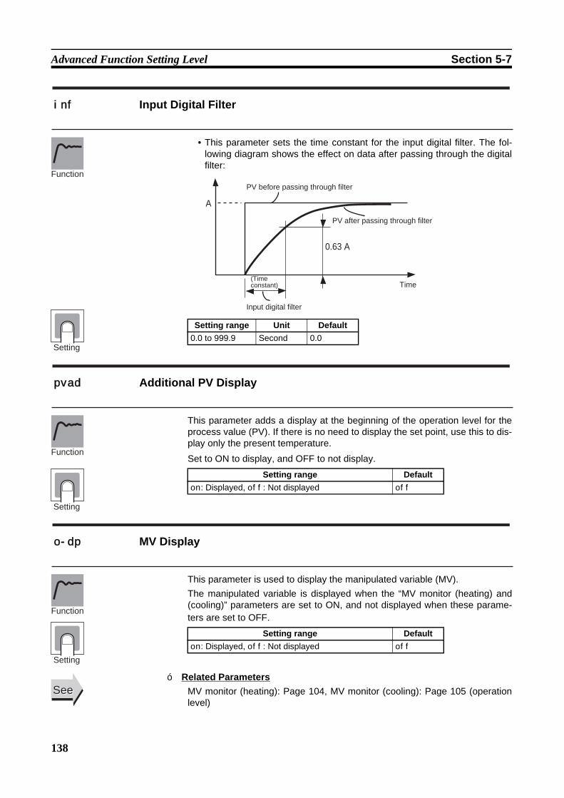
138
Advanced Function Setting Level Section 5-7
• This parameter sets the time constant for the input digital filter. The fol-lowing diagram shows the effect on data after passing through the digitalfilter:
This parameter adds a display at the beginning of the operation level for theprocess value (PV). If there is no need to display the set point, use this to dis-play only the present temperature.
Set to ON to display, and OFF to not display.
This parameter is used to display the manipulated variable (MV).The manipulated variable is displayed when the “MV monitor (heating) and(cooling)” parameters are set to ON, and not displayed when these parame-ters are set to OFF.
Related ParametersMV monitor (heating): Page 104, MV monitor (cooling): Page 105 (operationlevel)
inf Input Digital Filter
Setting range Unit Default0.0 to 999.9 Second 0.0
Function
0.63 A
A
PV before passing through filter
PV after passing through filter
(Time constant)
Input digital filter
Time
Setting
pvad Additional PV Display
Setting range Defaulton: Displayed, off: Not displayed off
Function
Setting
o-dp MV Display
Setting range Defaulton: Displayed, off: Not displayed off
Function
Setting
SeeSee■
139
Advanced Function Setting Level Section 5-7
• In the operation level or adjustment level, the display automaticallyreturns to the PV/SP if there are no key operations for the time set for thisparameter.
• The automatic display return time is disabled when the parameter is set toOFF. (In that case, the display will not be automatically switched.)
• When a parameter is set to ON, once the alarm function has turned ON itis held until the power is turned OFF. The latch can be canceled, how-ever, by switching to the initial setting level, communications setting level,or advanced function setting level.
• If alarm outputs are set to “close in alarm,” the outputs are kept closed. Ifthey are set to “open in alarm,” they are kept open.
Related ParametersAlarm value 1 to 3: Page 101 to 102, Alarm value upper limit 1 to 3: Page 103to 104, Alarm value lower limit 1 to 3: Page 103 to 104 (operation level)Alarm 1 to 3 type (initial setting level): Page 124 to 126Standby sequence reset: Page 133, Alarm 1 to 3 open in alarm: Page 134,Alarm 1 to 3 hysteresis: Page 135 (advanced function setting level)
ret Automatic Display Return Time
Setting range Unit DefaultOFF, 1 to 99 Second off
Function
Setting
a1lt Alarm 1 Latch Alarm 1 must be assigned, and the alarm 1 type must not be 0.
a2lt Alarm 2 Latch Alarm 2 must be assigned, and the alarm 2 type must not be 0.
a3lt Alarm 3 Latch Alarm 3 must be assigned, and the alarm 3 type must not be 0.
Setting range Defaulton: Enabled, off: Disabled off
Function
Setting
SeeSee■
140
Advanced Function Setting Level Section 5-7
• This parameter sets the key pressing time required to move to the protectlevel from the operation level or the adjustment level.
Related ParametersOperation/adjustment protect, initial setting/communications protect, settingchange protect (protect level): Page 96
• When this parameter is set to ON, alarm 1 output turns ON for inputerrors.The alarm 1 operation indicator will not light.Note For details on input errors, refer to Error Displays on page 156.
• The alarm 1 output is an OR output of alarm 1, HB alarm burnout/HSalarm, and input error.
• Output is turned OFF when switching to the initial setting level, communi-cations setting level, or advanced function setting level.
• Specifies whether cold junction compensation is to be performed inter-nally by the Controller or to be performed externally when the input typesetting is to between 5 and 22.
• The cold junction compensation external setting is enabled when the tem-perature difference is measured using two thermocouples or two ES1BSensors.
Related ParameterInput type (initial setting level): Page 119
prlt Move to Protect Level Time
Setting range Unit Default1 to 30 Second 3
Function
Setting
SeeSee
sero Input Error Output Alarm 1 must be assigned.
Setting range Defaulton: Enabled, off: Disabled off
Function
Setting
cjc Cold Junction Compensation Method Input type must be thermocouple or infrared temperature sensor
Setting range Defaulton: Internally, off: Externally on
Function
Setting
SeeSee
■
■
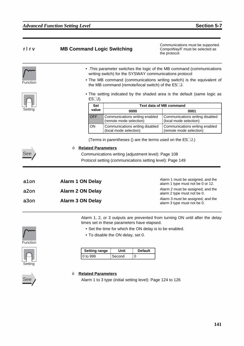
141
Advanced Function Setting Level Section 5-7
• .This parameter switches the logic of the MB command (communicationswriting switch) for the SYSWAY communications protocol
• The MB command (communications writing switch) is the equivalent ofthe MB command (remote/local switch) of the E5@J.
• The setting indicated by the shaded area is the default (same logic asE5@J).
(Terms in parentheses () are the terms used on the E5@J.)
Related ParametersCommunications writing (adjustment level): Page 108Protocol setting (communications setting level): Page 149
Alarm 1, 2, or 3 outputs are prevented from turning ON until after the delaytimes set in these parameters have elapsed.
• Set the time for which the ON delay is to be enabled.• To disable the ON delay, set 0.
Related ParametersAlarm 1 to 3 type (initial setting level): Page 124 to 126
rlrv MB Command Logic SwitchingCommunications must be supported.CompoWay/F must be selected as the protocol.
Set value
Text data of MB command0000 0001
OFF Communications writing enabled (remote mode selection)
Communications writing disabled (local mode selection)
ON Communications writing disabled (local mode selection)
Communications writing enabled (remote mode selection)
Function
Setting
SeeSee
a1on Alarm 1 ON Delay Alarm 1 must be assigned, and the alarm 1 type must not be 0 or 12.
a2on Alarm 2 ON Delay Alarm 2 must be assigned, and the alarm 2 type must not be 0.
a3on Alarm 3 ON Delay Alarm 3 must be assigned, and the alarm 3 type must not be 0.
Setting range Unit Default0 to 999 Second 0
Function
Setting
SeeSee
■
■
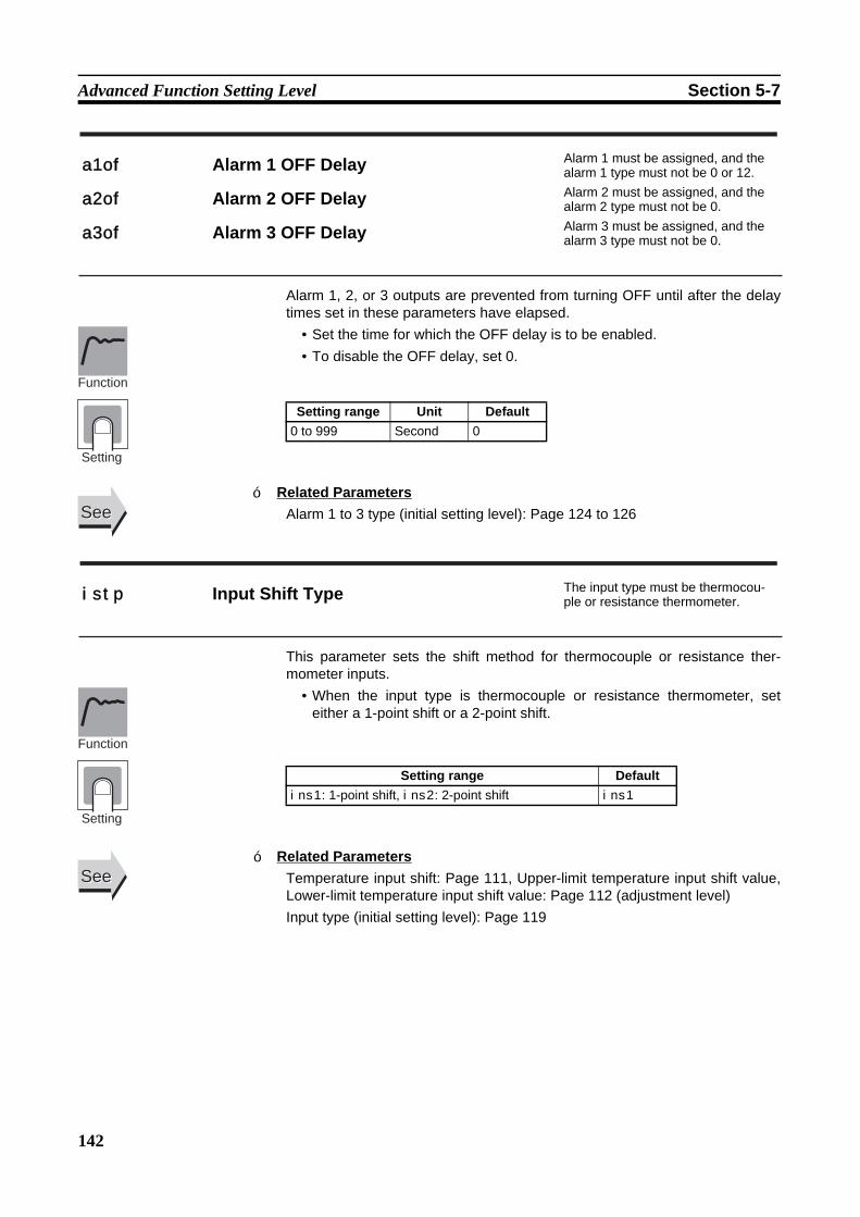
142
Advanced Function Setting Level Section 5-7
Alarm 1, 2, or 3 outputs are prevented from turning OFF until after the delaytimes set in these parameters have elapsed.
• Set the time for which the OFF delay is to be enabled.• To disable the OFF delay, set 0.
Related ParametersAlarm 1 to 3 type (initial setting level): Page 124 to 126
This parameter sets the shift method for thermocouple or resistance ther-mometer inputs.
• When the input type is thermocouple or resistance thermometer, seteither a 1-point shift or a 2-point shift.
Related ParametersTemperature input shift: Page 111, Upper-limit temperature input shift value,Lower-limit temperature input shift value: Page 112 (adjustment level)Input type (initial setting level): Page 119
a1of Alarm 1 OFF Delay Alarm 1 must be assigned, and the alarm 1 type must not be 0 or 12.
a2of Alarm 2 OFF Delay Alarm 2 must be assigned, and the alarm 2 type must not be 0.
a3of Alarm 3 OFF Delay Alarm 3 must be assigned, and the alarm 3 type must not be 0.
Setting range Unit Default0 to 999 Second 0
Function
Setting
SeeSee
istp Input Shift Type The input type must be thermocou-ple or resistance thermometer.
Setting range Defaultins1: 1-point shift, ins2: 2-point shift ins1
Function
Setting
SeeSee
■
■
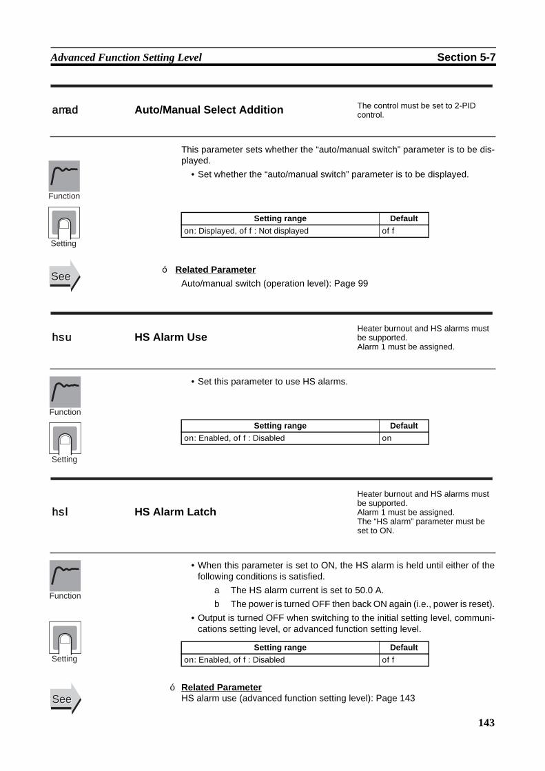
143
Advanced Function Setting Level Section 5-7
This parameter sets whether the “auto/manual switch” parameter is to be dis-played.
• Set whether the “auto/manual switch” parameter is to be displayed.
Related ParameterAuto/manual switch (operation level): Page 99
• Set this parameter to use HS alarms.
• When this parameter is set to ON, the HS alarm is held until either of thefollowing conditions is satisfied.
a The HS alarm current is set to 50.0 A.b The power is turned OFF then back ON again (i.e., power is reset).
• Output is turned OFF when switching to the initial setting level, communi-cations setting level, or advanced function setting level.
amad Auto/Manual Select Addition The control must be set to 2-PID control.
Setting range Defaulton: Displayed, off: Not displayed off
Function
Setting
SeeSee
hsu HS Alarm UseHeater burnout and HS alarms must be supported.Alarm 1 must be assigned.
Setting range Defaulton: Enabled, off: Disabled on
Function
Setting
hsl HS Alarm Latch
Heater burnout and HS alarms must be supported.Alarm 1 must be assigned.The “HS alarm” parameter must be set to ON.
Setting range Defaulton: Enabled, off: Disabled off
Function
Setting
SeeSeeRelated ParameterHS alarm use (advanced function setting level): Page 143
■
■

144
Advanced Function Setting Level Section 5-7
• This parameter sets the hysteresis for HS alarm.
Related ParameterHS alarm use (advanced function setting level): Page 143
This parameter enables or disables the LBA function and sets the detectiontime interval.
• Set the time interval for detecting loop burnouts.• To disable the LBA function, set 0.
Related ParametersAlarm 1 type (initial setting level): Page 124LBA level, LBA band: Page 145 (advanced function setting level)
hsh HS Alarm Hysteresis
Heater burnout and HS alarms must be supported.Alarm 1 must be assigned.The “HS alarm” parameter must be set to ON.The “HS alarm latch” must be set to OFF.
Setting range Unit Default0.1 to 50.0 A 0.1
Function
Setting
SeeSee
lba LBA Detection TimeAlarm 1 must be assigned.The alarm type must be set to 12 (LBA).
Setting range Unit Default0 to 9999 Second 0
Function
Setting
SeeSee
■
■

145
Advanced Function Setting Level Section 5-7
• This parameter sets the LBA level.• If the deviation between the SP and PV exceeds the LBA level, a loop
burnout is detected.
Note Set “none” as the unit for Controllers with Analog Inputs.
Related ParametersProcess value/set point (operation level): Page 99Alarm 1 type (initial setting level): Page 124LBA detection time: Page 144, LBA band: Page 145 (advanced function set-ting level)
• This parameter sets the LBA band.• If a control deviation greater than the LBA band is not reduced when the
LBA level is exceeded, an loop burnout is detected.
Note Set “none” as the unit for Controllers with Analog Inputs.
Related ParametersProcess value/set point (operation level): Page 99Alarm 1 type (initial setting level): Page 124LBA detection time: Page 144, LBA level: Page 145 (advanced function set-ting level)
lbal LBA LevelAlarm 1 must be assigned.The alarm type must be set to 12 (LBA).The LBA detection time must not be 0.
Models Setting range Unit DefaultControllers with Thermocouple/Resis-tance Thermometer Universal-inputs
0.1 to 999.9 °C or °F (See note.)
8.0
Controllers with Analog Inputs 0.01 to 99.99 %FS 10.00
Function
Setting
SeeSee
lbab LBA Band
Alarm 1 must be assigned.The alarm type must be set to 12 (LBA).The LBA detection time must not be 0.
Models Setting range Unit DefaultControllers with Thermocouple/Resis-tance Thermometer Universal-inputs
0.0 to 999.9 °C or °F (See note.)
3.0
Controllers with Analog Inputs 0.00 to 99.99 %FS 0.20
Function
Setting
SeeSee
■
■
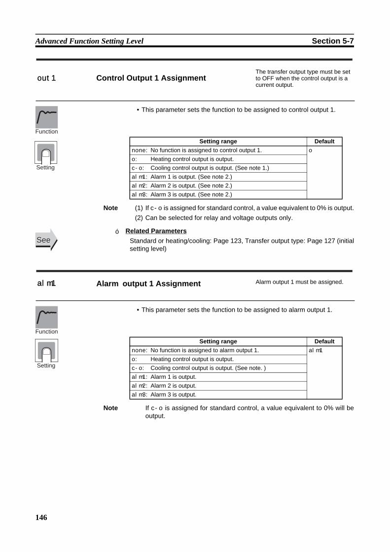
146
Advanced Function Setting Level Section 5-7
• This parameter sets the function to be assigned to control output 1.
Note (1) If c-o is assigned for standard control, a value equivalent to 0% is output.(2) Can be selected for relay and voltage outputs only.
Related ParametersStandard or heating/cooling: Page 123, Transfer output type: Page 127 (initialsetting level)
• This parameter sets the function to be assigned to alarm output 1.
Note If c-o is assigned for standard control, a value equivalent to 0% will beoutput.
out1 Control Output 1 AssignmentThe transfer output type must be set to OFF when the control output is a current output.
Setting range Defaultnone: No function is assigned to control output 1. o
o: Heating control output is output.c-o: Cooling control output is output. (See note 1.)alm1: Alarm 1 is output. (See note 2.)alm2: Alarm 2 is output. (See note 2.)alm3: Alarm 3 is output. (See note 2.)
Function
Setting
SeeSee
alm1 Alarm output 1 Assignment Alarm output 1 must be assigned.
Setting range Defaultnone: No function is assigned to alarm output 1. alm1
o: Heating control output is output.c-o: Cooling control output is output. (See note. )alm1: Alarm 1 is output.alm2: Alarm 2 is output.alm3: Alarm 3 is output.
Function
Setting
■

147
Advanced Function Setting Level Section 5-7
• This parameter sets the function to be assigned to alarm output 2.
Note (1) If c-o is assigned for standard control, a value equivalent to 0% will beoutput.
(2) If the “standard or heating/cooling” parameter is set to heating/coolingcontrol when there is E5CZ/CZ-U, control automatically switches to c-o.
Related ParametersStandard or heating/cooling: Page 123, (initial setting level)
alm2 Alarm output 2 Assignment Alarm output 2 must be assigned.
Setting range Defaultnone: No function is assigned to alarm output 2. alm2
(See note 2.)
o: Heating control output is output.c-o: Cooling control output is output. (See note 1.)alm1: Alarm 1 is output.alm2: Alarm 2 is output.alm3: Alarm 3 is output.
SeeSee■

148
Advanced Function Setting Level Section 5-7
• This parameter sets the function to be assigned to alarm output 3.
Note (1) If c-o is assigned for standard control, a value equivalent to 0% will beoutput.
(2) If the “standard or heating/cooling” parameter is set to heating/coolingcontrol when there is E5AZ/EZ, control automatically switches to c-o.
Related ParametersStandard or heating/cooling: Page 123, (initial setting level)
• This parameter switches the characters to be displayed.The following two types of characters can be displayed.11-segment display7-segment display
When set to on, an 11-segment display is used.
alm3 Alarm output 3 Assignment Alarm output 3 must be assigned (E5AZ and E5EZ only).
Setting range Defaultnone: No function is assigned to alarm output 3. alm3
(See note 2.)
o: Heating control output is output.c-o: Cooling control output is output. (See note 1.)alm1: Alarm 1 is output.alm2: Alarm 2 is output.alm3: Alarm 3 is output.
Function
Setting
SeeSee
csel Character Select
Setting range Defaulton: 11-segment display, off: 7-segment display on
Function
Setting
■

149
Communications Setting Level Section 5-8
5-8 Communications Setting Level
• Each parameter is enabled when the power is reset.• Match the communications specifications of the E5@Z and the host com-
puter. If multiple devices are connected, ensure that the communicationsspecifications for all devices in the system (except the Communicationsunit number) are the same.
Related ParameterCommunications writing (adjustment level): Page 108
psel Protocol Setting Communications must be supported.
u-no Communications Unit No.bps Communications Baud Ratelen Communications Data Length CompoWay/F must be selected as the protocol.
sbit Communications Stop Bits CompoWay/F must be selected as the protocol.
prty Communications Paritysdwt Send Data Wait Time
Function
Setting
Item Symbol Set values Settings DefaultProtocol setting psel cwf, mod CompoWay/F
(SYSWAY), Modbuscwf
Communications Unit No.
u-no 0 to 99 0 to 99 1
Communications baud rate
bps 1.2, 2.4, 4.8, 9.6, 19.2, or 38.4 (kbps)
1.2, 2.4, 4.8, 9.6, 19.2, or 38.4 (kbps)
9.6
Communications data length
len 7, 8 (bits) 7, 8 (bits) 7
Communications stop bits
sbit 1, 2 1, 2 2
Communications parity prty none, even, odd None, Even, Odd even
Send data wait time sdwt 0 to 99 0 to 99 (ms) 20
SeeSee■

150
Communications Setting Level Section 5-8
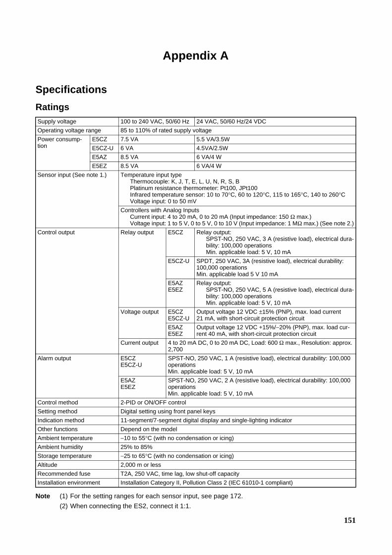
151
Appendix A
SpecificationsRatings
Note (1) For the setting ranges for each sensor input, see page 172.(2) When connecting the ES2, connect it 1:1.
Supply voltage 100 to 240 VAC, 50/60 Hz 24 VAC, 50/60 Hz/24 VDCOperating voltage range 85 to 110% of rated supply voltagePower consump-tion
E5CZ 7.5 VA 5.5 VA/3.5WE5CZ-U 6 VA 4.5VA/2.5WE5AZ 8.5 VA 6 VA/4 WE5EZ 8.5 VA 6 VA/4 W
Sensor input (See note 1.) Temperature input typeThermocouple: K, J, T, E, L, U, N, R, S, BPlatinum resistance thermometer: Pt100, JPt100Infrared temperature sensor: 10 to 70°C, 60 to 120°C, 115 to 165°C, 140 to 260°CVoltage input: 0 to 50 mV
Controllers with Analog InputsCurrent input: 4 to 20 mA, 0 to 20 mA (Input impedance: 150 Ω max.)Voltage input: 1 to 5 V, 0 to 5 V, 0 to 10 V (Input impedance: 1 MΩ max.) (See note 2.)
Control output Relay output E5CZ Relay output:SPST-NO, 250 VAC, 3 A (resistive load), electrical dura-bility: 100,000 operationsMin. applicable load: 5 V, 10 mA
E5CZ-U SPDT, 250 VAC, 3A (resistive load), electrical durability: 100,000 operationsMin. applicable load 5 V 10 mA
E5AZE5EZ
Relay output:SPST-NO, 250 VAC, 5 A (resistive load), electrical dura-bility: 100,000 operationsMin. applicable load: 5 V, 10 mA
Voltage output E5CZE5CZ-U
Output voltage 12 VDC ±15% (PNP), max. load current 21 mA, with short-circuit protection circuit
E5AZE5EZ
Output voltage 12 VDC +15%/−20% (PNP), max. load cur-rent 40 mA, with short-circuit protection circuit
Current output 4 to 20 mA DC, 0 to 20 mA DC, Load: 600 Ω max., Resolution: approx. 2,700
Alarm output E5CZE5CZ-U
SPST-NO, 250 VAC, 1 A (resistive load), electrical durability: 100,000 operationsMin. applicable load: 5 V, 10 mA
E5AZE5EZ
SPST-NO, 250 VAC, 2 A (resistive load), electrical durability: 100,000 operationsMin. applicable load: 5 V, 10 mA
Control method 2-PID or ON/OFF controlSetting method Digital setting using front panel keysIndication method 11-segment/7-segment digital display and single-lighting indicatorOther functions Depend on the modelAmbient temperature −10 to 55°C (with no condensation or icing)Ambient humidity 25% to 85%Storage temperature −25 to 65°C (with no condensation or icing)Altitude 2,000 m or lessRecommended fuse T2A, 250 VAC, time lag, low shut-off capacityInstallation environment Installation Category II, Pollution Class 2 (IEC 61010-1 compliant)

152
Appendix A
HB and HS Alarms (for Controller with Heater Burnout and HS Alarms)
Note (1) When the control output 1 ON time is less than 190 ms, heater burnout detection and heater currentmeasurement are not performed.
(2) When the control output 1 OFF time is less than 190 ms, HS alarm and leakage current measure-ment are not performed.
Characteristics
Max. heater current 50 A AC Input current indication accuracy ±5% FS ±1 digit max.Heater burnout alarm setting range
0.1 to 49.9 A (in units of 0.1A)0.0 A: Heater burnout alarm output turns OFF.50.0 A: Heater burnout alarm output turns ON.Min. detection ON time: 190 ms (See note 1.)
HS alarm setting range 0.1 to 49.9 A (in units of 0.1A)0.0 A: HS alarm output turns ON.50.0 A: HS alarm output turns OFF.Min. detection OFF time: 190 ms (See note 2.)
Indication accuracy(ambient temperature of 23°C)
Thermocouple (See note 1.):E5CZ/AZ/EZ: (±0.5% of indication value or ±1°C, whichever is greater) ±1 digit max.E5CZ-U: (±1% of indication value or ±2°C, whichever is greater) ±1 digit max.
Platinum resistance thermometer:(±0.5% of indication value or ±1°C, whichever is greater) ±1 digit max.
Analog input: ±0.5% FS ±1 digit max.CT input: ±5% FS ±1 digit max.
Temperature variation influence (See note 2.)
Thermocouple (R, S, B)(±1% of PV or ±10°C, whichever is greater) ±1 digit max. (E5CZ)(±2% of PV or ±10°C, whichever is greater) ±1 digit max. (E5CZ-U)Other thermocouples:(±1% of PV or ±4°C, whichever is greater) ±1 digit max. (E5CZ)(±2% of PV or ±4°C, whichever is greater) ±1 digit max. (E5CZ-U) *K thermocouple at −100°C max: ±10°C max.Platinum resistance thermometer:(±1% of PV or ±2°C, whichever is greater) ±1 digit max.Analog input: ±1% FS ±1 digit max. (See note 2.)
Voltage variation influence (See note 2.)
Hysteresis Controllers with Thermocou-ple/Resistance Thermome-ter Universal-inputs
0.1 to 999.9°C or °F)(in units of 0.1°C or °F) (See note 3.)
Controllers with Analog Inputs
0.01% to 99.99% FS (in units of 0.01% FS)
Proportional band (P) Controllers with Thermocou-ple/Resistance Thermome-ter Universal-inputs
0.1 to 999.9°C or °F)(in units of 0.1 EU) (See note 3.)
Controllers with Analog Inputs
0.1% to 999.9% FS (in units of 0.1% FS)
Integral time (I) 0 to 3,999 s (in units of 1 s)Derivative time (D) 0 to 3,999 s (in units of 1 s)Control Period 0.5, 1 to 99 s (in units of 1 s)Manual reset value 0.0% to 100.0% (in units of 0.1%)Alarm setting range −1,999 to 9,999 (decimal point position depends on input type)Sampling period 250 msAffect of signal source resis-tance
Thermocouple:0.1°C/Ω max.(100Ωmax.)(See note 4.)
Platinum resistance thermometer:0.4°C/Ωmax.(10Ωmax.)Insulation resistance 20 MΩ min. (at 500 VDC)Dielectric strength 2,000 VAC, 50/60 Hz for 1 min between terminals of different chargeMalfunction vibration 10 to 55 Hz, 20 m/s2 for 10 min each in X, Y and Z directionsVibration resistance 10 to 55 Hz, peak height amplitude of 0.75 mm for 2 hr each in X, Y, and Z directionsMalfunction shock 100 m/s2, 3 times each in X, Y, and Z directions
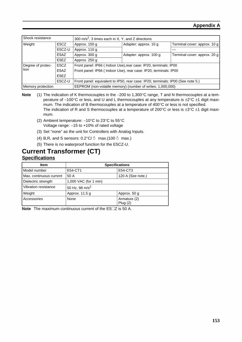
153
Appendix A
Note (1) The indication of K thermocouples in the −200 to 1,300°C range, T and N thermocouples at a tem-perature of −100°C or less, and U and L thermocouples at any temperature is ±2°C ±1 digit maxi-mum. The indication of B thermocouples at a temperature of 400°C or less is not specified.The indication of R and S thermocouples at a temperature of 200°C or less is ±3°C ±1 digit maxi-mum.
(2) Ambient temperature: −10°C to 23°C to 55°CVoltage range: −15 to +10% of rated voltage
(3) Set “none” as the unit for Controllers with Analog Inputs.
(4) B,R, and S sensors: 0.2°C/Ω max.(100Ω max.)(5) There is no waterproof function for the E5CZ-U.
Current Transformer (CT)Specifications
Note The maximum continuous current of the E5@Z is 50 A.
Shock resistance 300 m/s2, 3 times each in X, Y, and Z directionsWeight E5CZ Approx. 150 g Adapter: approx. 10 g Terminal cover: approx. 10 g
E5CZ-U Approx. 110 g ---E5AZ Approx. 300 g Adapter: approx. 100 g Terminal cover: approx. 20 gE5EZ Approx. 250 g
Degree of protec-tion
E5CZE5AZE5EZ
Front panel: IP66 ( Indoor Use),rear case: IP20, terminals: IP00Front panel: IP66 ( Indoor Use), rear case: IP20, terminals: IP00
E5CZ-U Front panel: equivalent to IP50, rear case: IP20, terminals: IP00 (See note 5.)Memory protection EEPROM (non-volatile memory) (number of writes: 1,000,000)
Item SpecificationsModel number E54-CT1 E54-CT3Max. continuous current 50 A 120 A (See note.)Dielectric strength 1,000 VAC (for 1 min)Vibration resistance 50 Hz, 98 m/s2
Weight Approx. 11.5 g Approx. 50 gAccessories None Armature (2)
Plug (2)
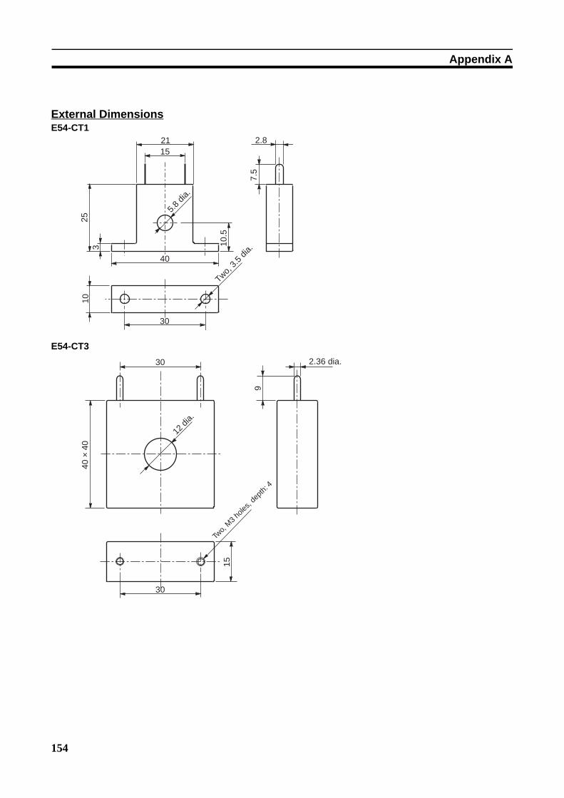
154
Appendix A
External DimensionsE54-CT1
E54-CT3
2115
253
40
10.5
5.8
dia.
7.5
2.8
10
30
Two, 3
.5 d
ia.
30
40 ×
40
12 d
ia.
9
2.36 dia.
15
30
Two,
M3 ho
les, d
epth
: 4
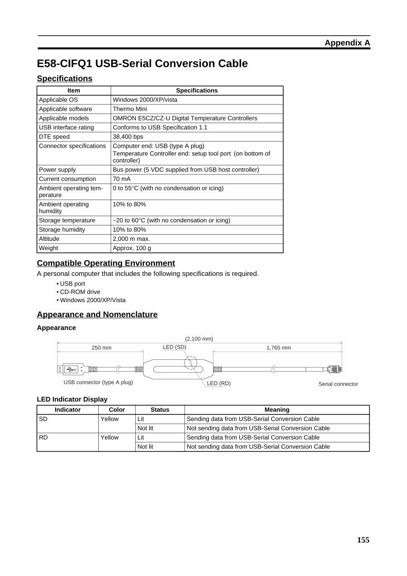
155
Appendix A
E58-CIFQ1 USB-Serial Conversion CableSpecifications
Compatible Operating EnvironmentA personal computer that includes the following specifications is required.
• USB port• CD-ROM drive• Windows 2000/XP/Vista
Appearance and NomenclatureAppearance
LED Indicator Display
Item SpecificationsApplicable OS Windows 2000/XP/vistaApplicable software Thermo MiniApplicable models OMRON E5CZ/CZ-U Digital Temperature ControllersUSB interface rating Conforms to USB Specification 1.1DTE speed 38,400 bpsConnector specifications Computer end: USB (type A plug)
Temperature Controller end: setup tool port (on bottom of controller)
Power supply Bus power (5 VDC supplied from USB host controller) Current consumption 70 mAAmbient operating tem-perature
0 to 55°C (with no condensation or icing)
Ambient operating humidity
10% to 80%
Storage temperature −20 to 60°C (with no condensation or icing)Storage humidity 10% to 80%Altitude 2,000 m max.Weight Approx. 100 g
250 mm LED (SD)
(2,100 mm)
LED (RD)USB connector (type A plug)
1,765 mm
Serial connector
Indicator Color Status MeaningSD Yellow Lit Sending data from USB-Serial Conversion Cable
Not lit Not sending data from USB-Serial Conversion CableRD Yellow Lit Sending data from USB-Serial Conversion Cable
Not lit Not sending data from USB-Serial Conversion Cable
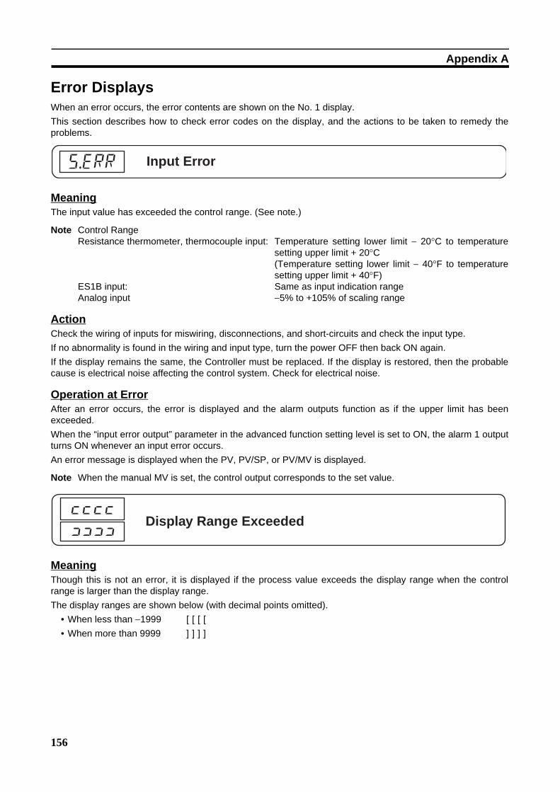
156
Appendix A
Error DisplaysWhen an error occurs, the error contents are shown on the No. 1 display.This section describes how to check error codes on the display, and the actions to be taken to remedy theproblems.
MeaningThe input value has exceeded the control range. (See note.)
Note Control RangeResistance thermometer, thermocouple input: Temperature setting lower limit − 20°C to temperature
setting upper limit + 20°C(Temperature setting lower limit − 40°F to temperaturesetting upper limit + 40°F)
ES1B input: Same as input indication rangeAnalog input −5% to +105% of scaling range
ActionCheck the wiring of inputs for miswiring, disconnections, and short-circuits and check the input type.If no abnormality is found in the wiring and input type, turn the power OFF then back ON again.If the display remains the same, the Controller must be replaced. If the display is restored, then the probablecause is electrical noise affecting the control system. Check for electrical noise.
Operation at ErrorAfter an error occurs, the error is displayed and the alarm outputs function as if the upper limit has beenexceeded.When the “input error output” parameter in the advanced function setting level is set to ON, the alarm 1 outputturns ON whenever an input error occurs.An error message is displayed when the PV, PV/SP, or PV/MV is displayed.
Note When the manual MV is set, the control output corresponds to the set value.
MeaningThough this is not an error, it is displayed if the process value exceeds the display range when the controlrange is larger than the display range.The display ranges are shown below (with decimal points omitted).
• When less than −1999 [[[[
• When more than 9999 ]]]]
Input Errors.err
Display Range Exceeded[[[[
]]]]
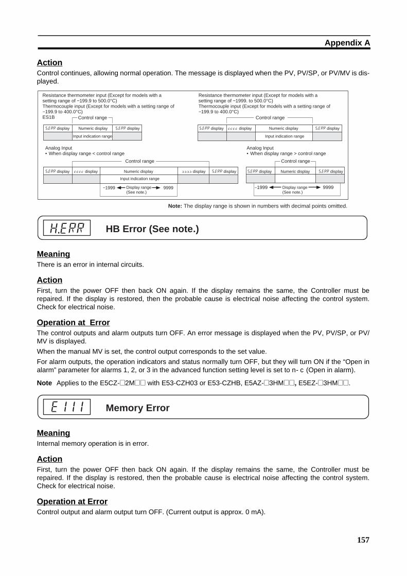
157
Appendix A
ActionControl continues, allowing normal operation. The message is displayed when the PV, PV/SP, or PV/MV is dis-played.
MeaningThere is an error in internal circuits.
ActionFirst, turn the power OFF then back ON again. If the display remains the same, the Controller must berepaired. If the display is restored, then the probable cause is electrical noise affecting the control system.Check for electrical noise.
Operation at ErrorThe control outputs and alarm outputs turn OFF. An error message is displayed when the PV, PV/SP, or PV/MV is displayed.When the manual MV is set, the control output corresponds to the set value.For alarm outputs, the operation indicators and status normally turn OFF, but they will turn ON if the “Open inalarm” parameter for alarms 1, 2, or 3 in the advanced function setting level is set to n-c (Open in alarm).
Note Applies to the E5CZ-@2M@@ with E53-CZH03 or E53-CZHB, E5AZ-@3HM@@, E5EZ-@3HM@@.
MeaningInternal memory operation is in error.
ActionFirst, turn the power OFF then back ON again. If the display remains the same, the Controller must berepaired. If the display is restored, then the probable cause is electrical noise affecting the control system.Check for electrical noise.
Operation at ErrorControl output and alarm output turn OFF. (Current output is approx. 0 mA).
−1999 9999 −1999 9999
Resistance thermometer input (Except for models with a setting range of −199.9 to 500.0°C)Thermocouple input (Except for models with a setting range of −199.9 to 400.0°C)ES1B Control range
s.err display Numeric display s.err display
Input indication range
Analog Input• When display range < control range
Control range
s.err display [[[[ display Numeric display
Input indication range
]]]] display s.err display
Display range (See note.)
Resistance thermometer input (Except for models with a setting range of −1999. to 500.0°C)Thermocouple input (Except for models with a setting range of −199.9 to 400.0°C)
Control range
s.err display [[[[ display Numeric display
Input indication range
s.err display
Analog Input• When display range > control range
Control range
s.err display Numeric display s.err display
Display range (See note.)
Note: The display range is shown in numbers with decimal points omitted.
HB Error (See note.)h.err
Memory Errore111

158
Appendix A
MeaningThis error is displayed when the heater current value exceeds 55.0 A.
ActionControl continues, allowing normal operation. An error message is displayed when the following items are dis-played.
Heater current 1 value monitorLeakage current 1 monitor
MeaningWhen heater burnout or an HS alarm occurs, the No. 1 display in the applicable setting level flashes.
ActionWhen either heater burnout or HS is detected, the HA indicator lights and the No. 1 display flashes for theapplicable “heater current 1 value monitor,” or “leakage current 1 monitor” parameters in the operation leveland adjustment level. Control continues, allowing normal operation.
TroubleshootingChecking ProblemsIf the Temperature Controller is not operating normally, check the following points before requesting repairs. Ifthe problem persists, contact your OMRON representative for details on returning the product.
Timing Status Meaning Countermeasures PageTurning ON the power for the first time
Temperature unit (°C/°F) is flashing.
ST (self-tuning) is in progress (default setting: ON).
This is not a product fault. The temperature unit (°C/°F) flashes while ST (self-tuning) is being performed
44
Temperature error is large.Input error (S.Err dis-play)
Input type mismatch Check the sensor type and reset the input type correctly.
34
Thermometer is not installed properly.
Check the thermometer installation location and polarity and install correctly.
21
Communications are not possible.
Non-recommended adapter is being used.
Make sure that the connected device is not faulty.
Section 1 of Communi-cations Manual
Current Value Exceedsffff
Heater BurnoutHS Alarm
lcr1
ct1
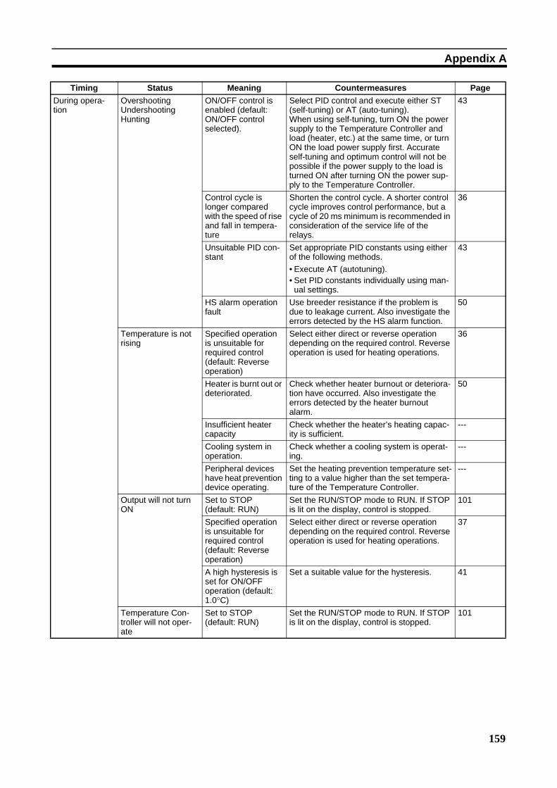
159
Appendix A
During opera-tion
OvershootingUndershootingHunting
ON/OFF control is enabled (default: ON/OFF control selected).
Select PID control and execute either ST (self-tuning) or AT (auto-tuning). When using self-tuning, turn ON the power supply to the Temperature Controller and load (heater, etc.) at the same time, or turn ON the load power supply first. Accurate self-tuning and optimum control will not be possible if the power supply to the load is turned ON after turning ON the power sup-ply to the Temperature Controller.
43
Control cycle is longer compared with the speed of rise and fall in tempera-ture
Shorten the control cycle. A shorter control cycle improves control performance, but a cycle of 20 ms minimum is recommended in consideration of the service life of the relays.
36
Unsuitable PID con-stant
Set appropriate PID constants using either of the following methods.• Execute AT (autotuning).• Set PID constants individually using man-
ual settings.
43
HS alarm operation fault
Use breeder resistance if the problem is due to leakage current. Also investigate the errors detected by the HS alarm function.
50
Temperature is not rising
Specified operation is unsuitable for required control (default: Reverse operation)
Select either direct or reverse operation depending on the required control. Reverse operation is used for heating operations.
36
Heater is burnt out or deteriorated.
Check whether heater burnout or deteriora-tion have occurred. Also investigate the errors detected by the heater burnout alarm.
50
Insufficient heater capacity
Check whether the heater’s heating capac-ity is sufficient.
---
Cooling system in operation.
Check whether a cooling system is operat-ing.
---
Peripheral devices have heat prevention device operating.
Set the heating prevention temperature set-ting to a value higher than the set tempera-ture of the Temperature Controller.
---
Output will not turn ON
Set to STOP (default: RUN)
Set the RUN/STOP mode to RUN. If STOP is lit on the display, control is stopped.
101
Specified operation is unsuitable for required control (default: Reverse operation)
Select either direct or reverse operation depending on the required control. Reverse operation is used for heating operations.
37
A high hysteresis is set for ON/OFF operation (default: 1.0°C)
Set a suitable value for the hysteresis. 41
Temperature Con-troller will not oper-ate
Set to STOP (default: RUN)
Set the RUN/STOP mode to RUN. If STOP is lit on the display, control is stopped.
101
Timing Status Meaning Countermeasures Page

160
Appendix A
Note The tightening torque for E5CZ-U is 0.5 N·m.
During opera-tion (continued)
Temperature error is largeInput error (S.err dis-play)
Thermometer has burnt out or short-cir-cuited.
Check whether the thermometer has burnt out or short-circuited
---
Thermometer lead wires and power lines are in the same conduit, causing noise from the power lines (generally, dis-play values will be unstable).
Wire the lead wires and power lines in sep-arate conduits, or wiring using a more direct path.
---
Connection between the Temperature Controller and ther-mocouple is using copper wires.
Connect the thermocouple’s lead wires directly, or connect a compensating con-ductor suitable for the thermocouple.
---
Installation location of thermometer is unsuitable.
Check whether the location of the thermom-eter is suitable.
---
Input shift is not set correctly (default: 0°C)
Set a suitable input shift. If input shift is not required, set the input shift value to 0.0.
59
Keys will not operate Setting change pro-tect is ON.
Turn OFF setting change protect. 78
Cannot shift levels Operations limited due to protection.
Set the operation/adjustment protect, initial setting/communications protect, and set-ting change protect values as required.
78
After long ser-vice life
Control is unstable Terminal screws may be loose.
Retighten terminal screws to a torque of 0.74 to 0.90 N·m. (See Note.)
22
The internal compo-nents have reached the end of their ser-vice life.
The Temperature Controller’s internal elec-trolytic capacitor depends on the ambient temperature, and load rate. The structural life depends on the ambient environment (shock, vibration). The life expectancy of the output relays varies greatly with the switching capacity and other switching con-ditions. Always use the output relays within their rated load and electrical life expect-ancy. If an output relay is used beyond its life expectancy, its contacts may become welded or burned. Replace the Tempera-ture Controller and all other Temperature Controllers purchased in the same time period.
---
Timing Status Meaning Countermeasures Page

161
Appendix A
Symptom: Cannot Communicate or a Communications Error Occurs
Meaning CountermeasuresThe communications wiring is not correct. Correct the wiring.The communications line has become dis-connected
Correct the communications line securely and tighten the screws.
The communications cable is broken. Replace the cable.The communications cable is too long. The total cable length is 500 m maximum for RS-485 and 15 m maximum for
RS-232C communications.To extend the communications distance for RS-232C communications, use OMRON's Z3R Optical Interface.
The wrong communications cable has been used.
Use a shielded, twisted-pair AWG24 to AWG14(cross-sectional area of 0.205 to 2.081 mm2)cable for the communications cable.
More than the specified number of commu-nications devices are connected to the same communications path for RS-485 communications.
When 1:N RS-485 communications are used, a maximum of 32 nodes(including the host node) can be connected.
An end node has not been set at each end of the communications line for RS-485 communications.
Set or connect terminating resistance at each end of the line. If the E5CZ, E5AZ,or E5EZ is the end node, use 120-Ω (1/2-W) terminating resistance. The combined terminating resistance with the host device must be at least 54Ω
The specified power supply voltage is not being supplied to the Controller.
Supply the specified power supply voltage.
The specified power supply voltage is not being supplied to an Interface Converter (such as the K3SC) .
Supply the specified power supply voltage.
The same baud rate and communications method are not being used by all of the Controllers, host devices, and other devices on the same communications line.
Set the same values for the baud rate, protocol, data length, stop bits, and parity on all nodes.
The unit number specified in the command frame is different from the unit number set by the Controller.
Use the same unit number.
The same unit number as the Controller is being used for another node on the same communications line for RS-485 communi-cations.
Set each unit number for only one node.
There is a mistake in programming the host device.
Use a line monitor to check the commands. Check operation using a sample program.
The host device is detecting the absence of a response as an error before it receives the response from the Controller.
Shorten the send data wait time in the Controller or increase the response wait time in the host device.
The host device is detecting the absence of a response as an error after broadcast-ing a command(except for SYSWAY).
The Controller does not return responses for broadcast commands.
The host device sent another command before receiving a response from the Con-troller.
The response must always be read after sending a command (except for broadcast commands).
The host device sent the next command too soon after receiving a response from the Controller.
After receiving a response, wait at least 2 ms before sending the next com-mand.

162
Appendix A
Note For details on errors, refer to E5CZ/E5AZ/E5EZ Digital Temperature Controllers Communications Manual(Cat. No. H208).
Meaning CountermeasuresThe communications line became unsta-ble when Controller power was turned ON or interrupted, and the host device read the unstable status as data.
Initialize the reception buffer in the host device before sending the first com-mand and after turning OFF the power to the Controller.
The communications data was corrupted from noise from the environment.
Try using a slower baud rate.Separate the communications cable from the source of noise.Use a shielded, twisted-pair cable for the communications cable.Use as short a communications cable as possible, and do not lay or loop extra cable.To prevent inductive noise, do not run the communications cable parallel to a power line.If noise countermeasures are difficult to implement, use an Optical Interface.
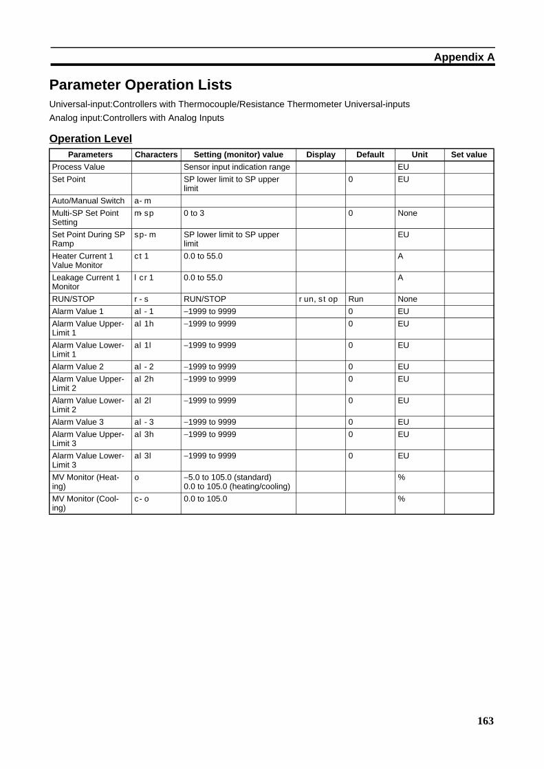
163
Appendix A
Parameter Operation ListsUniversal-input:Controllers with Thermocouple/Resistance Thermometer Universal-inputsAnalog input:Controllers with Analog Inputs
Operation LevelParameters Characters Setting (monitor) value Display Default Unit Set value
Process Value Sensor input indication range EUSet Point SP lower limit to SP upper
limit0 EU
Auto/Manual Switch a-m
Multi-SP Set Point Setting
m-sp 0 to 3 0 None
Set Point During SP Ramp
sp-m SP lower limit to SP upper limit
EU
Heater Current 1 Value Monitor
ct1 0.0 to 55.0 A
Leakage Current 1 Monitor
lcr1 0.0 to 55.0 A
RUN/STOP r-s RUN/STOP run, stop Run NoneAlarm Value 1 al-1 −1999 to 9999 0 EUAlarm Value Upper-Limit 1
al1h −1999 to 9999 0 EU
Alarm Value Lower-Limit 1
al1l −1999 to 9999 0 EU
Alarm Value 2 al-2 −1999 to 9999 0 EUAlarm Value Upper-Limit 2
al2h −1999 to 9999 0 EU
Alarm Value Lower-Limit 2
al2l −1999 to 9999 0 EU
Alarm Value 3 al-3 −1999 to 9999 0 EUAlarm Value Upper-Limit 3
al3h −1999 to 9999 0 EU
Alarm Value Lower-Limit 3
al3l −1999 to 9999 0 EU
MV Monitor (Heat-ing)
o −5.0 to 105.0 (standard)0.0 to 105.0 (heating/cooling)
%
MV Monitor (Cool-ing)
c-o 0.0 to 105.0 %
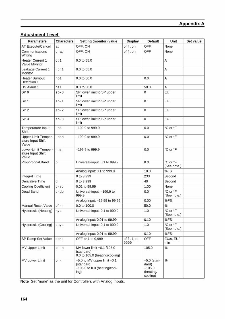
164
Appendix A
Adjustment Level Parameters Characters Setting (monitor) value Display Default Unit Set value
AT Execute/Cancel at OFF, ON off, on OFF NoneCommunications Writing
cmwt OFF, ON off, on OFF None
Heater Current 1 Value Monitor
ct1 0.0 to 55.0 A
Leakage Current 1 Monitor
lcr1 0.0 to 55.0 A
Heater Burnout Detection 1
hb1 0.0 to 50.0 0.0 A
HS Alarm 1 hs1 0.0 to 50.0 50.0 ASP 0 sp-0 SP lower limit to SP upper
limit0 EU
SP 1 sp-1 SP lower limit to SP upper limit
0 EU
SP 2 sp-2 SP lower limit to SP upper limit
0 EU
SP 3 sp-3 SP lower limit to SP upper limit
0 EU
Temperature Input Shift
ins −199.9 to 999.9 0.0 °C or °F
Upper-Limit Temper-ature Input Shift Value
insh −199.9 to 999.9 0.0 °C or °F
Lower-Limit Temper-ature Input Shift Value
insl −199.9 to 999.9 0.0 °C or °F
Proportional Band p Universal-input: 0.1 to 999.9 8.0 °C or °F (See note.)
Analog input: 0.1 to 999.9 10.0 %FSIntegral Time i 0 to 3,999 233 SecondDerivative Time d 0 to 3,999 40 SecondCooling Coefficient c-sc 0.01 to 99.99 1.00 NoneDead Band c-db Universal-input: −199.9 to
999.90.0 °C or °F
(See note.)Analog input: −19.99 to 99.99 0.00 %FS
Manual Reset Value of-r 0.0 to 100.0 50.0 %Hysteresis (Heating) hys Universal-input: 0.1 to 999.9 1.0 °C or °F
(See note.)Analog input: 0.01 to 99.99 0.10 %FS
Hysteresis (Cooling) chys Universal-input: 0.1 to 999.9 1.0 °C or °F (See note.)
Analog input: 0.01 to 99.99 0.10 %FSSP Ramp Set Value sprt OFF or 1 to 9,999 off, 1 to
9999
OFF EU/s, EU/min
MV Upper Limit ol-h MV lower limit +0.1 /105.0 (standard)0.0 to 105.0 (heating/cooling)
105.0 %
MV Lower Limit ol-l −5.0 to MV upper limit −0.1 (standard)−105.0 to 0.0 (heating/cool-ing)
−5.0 (stan-dard)−105.0 (heating/cooling)
%
Note Set “none” as the unit for Controllers with Analog Inputs.
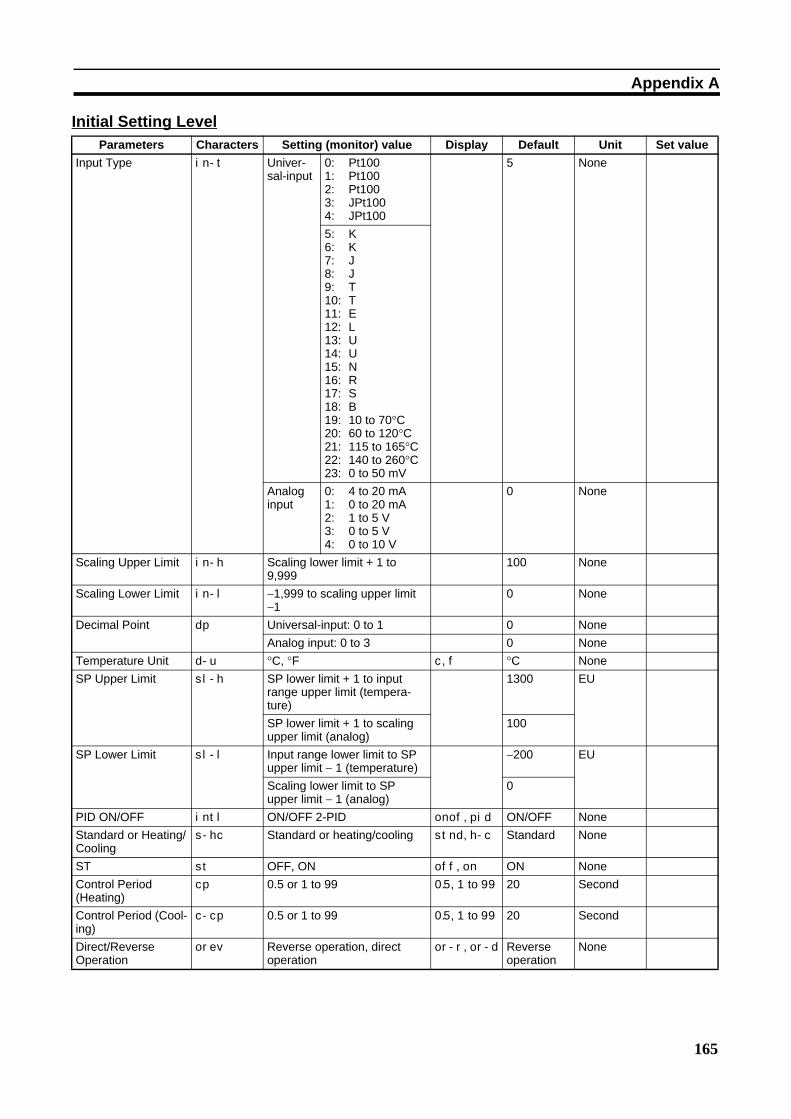
165
Appendix A
Initial Setting LevelParameters Characters Setting (monitor) value Display Default Unit Set value
Input Type in-t Univer-sal-input
0: Pt1001: Pt1002: Pt1003: JPt1004: JPt100
5 None
5: K6: K7: J8: J9: T10: T11: E12: L13: U14: U15: N16: R17: S18: B19: 10 to 70°C20: 60 to 120°C21: 115 to 165°C22: 140 to 260°C23: 0 to 50 mV
Analog input
0: 4 to 20 mA1: 0 to 20 mA2: 1 to 5 V3: 0 to 5 V4: 0 to 10 V
0 None
Scaling Upper Limit in-h Scaling lower limit + 1 to 9,999
100 None
Scaling Lower Limit in-l −1,999 to scaling upper limit −1
0 None
Decimal Point dp Universal-input: 0 to 1 0 NoneAnalog input: 0 to 3 0 None
Temperature Unit d-u °C, °F c, f °C NoneSP Upper Limit sl-h SP lower limit + 1 to input
range upper limit (tempera-ture)
1300 EU
SP lower limit + 1 to scaling upper limit (analog)
100
SP Lower Limit sl-l Input range lower limit to SP upper limit − 1 (temperature)
−200 EU
Scaling lower limit to SP upper limit − 1 (analog)
0
PID ON/OFF intl ON/OFF 2-PID onof, pid ON/OFF NoneStandard or Heating/Cooling
s-hc Standard or heating/cooling stnd, h-c Standard None
ST st OFF, ON off, on ON NoneControl Period (Heating)
cp 0.5 or 1 to 99 0.5, 1 to 99 20 Second
Control Period (Cool-ing)
c-cp 0.5 or 1 to 99 0.5, 1 to 99 20 Second
Direct/Reverse Operation
orev Reverse operation, direct operation
or-r, or-d Reverse operation
None

166
Appendix A
Alarm 1 Type alt1 0: Alarm function OFF1: Upper and lower-limit
alarm2: Upper-limit alarm3: Lower-limit alarm4: Upper and lower-limit
range alarm5: Upper and lower-limit
alarm with standby sequence
6: Upper-limit alarm with standby sequence
7: Lower-limit alarm with standby sequence
8: Absolute-value upper-limit alarm
9: Absolute-value lower-limit alarm
10: Absolute-value upper-limit alarm with standby sequence
11: Absolute-value lower-limit alarm with standby sequence
12: LBA (Loop Break Alarm)
2 None
Alarm 2 Type alt2 0: Alarm function OFF1: Upper and lower-limit
alarm2: Upper-limit alarm3: Lower-limit alarm4: Upper and lower-limit
range alarm5: Upper and lower-limit
alarm with standby sequence
6: Upper-limit alarm with standby sequence
7: Lower-limit alarm with standby sequence
8: Absolute-value upper-limit alarm
9: Absolute-value lower-limit alarm
10: Absolute-value upper-limit alarm with standby sequence
11: Absolute-value lower-limit alarm with standby sequence
2 None
Alarm 3 Type alt3 Same settings as the alarm 2 type
2 None
Transfer Output Type
tr-t OFF: OFFSP: Set pointSP-M: Set point during SP
rampPV: Process valueMV: Manipulated variable
(heating)C-MV: Manipulated variable
(cooling)
off
sp
sp-m
pv
mv
c-mv
OFF None
Transfer Output Upper Limit
tr-h See note. See note. See note.
Transfer Output Lower Limit
tr-l See note. See note. See note.
Parameters Characters Setting (monitor) value Display Default Unit Set value
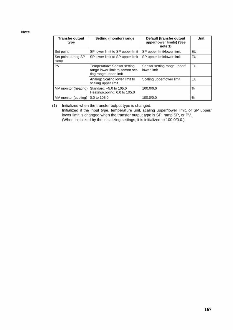
167
Note
(1) Initialized when the transfer output type is changed.Initialized if the input type, temperature unit, scaling upper/lower limit, or SP upper/lower limit is changed when the transfer output type is SP, ramp SP, or PV.(When initialized by the initializing settings, it is initialized to 100.0/0.0.)
Transfer output type
Setting (monitor) range Default (transfer output upper/lower limits) (See
note 1)
Unit
Set point SP lower limit to SP upper limit SP upper limit/lower limit EUSet point during SP ramp
SP lower limit to SP upper limit SP upper limit/lower limit EU
PV Temperature: Sensor setting range lower limit to sensor set-ting range upper limit
Sensor setting range upper/lower limit
EU
Analog: Scaling lower limit to scaling upper limit
Scaling upper/lower limit EU
MV monitor (heating) Standard: −5.0 to 105.0Heating/cooling: 0.0 to 105.0
100.0/0.0 %
MV monitor (cooling) 0.0 to 105.0 100.0/0.0 %
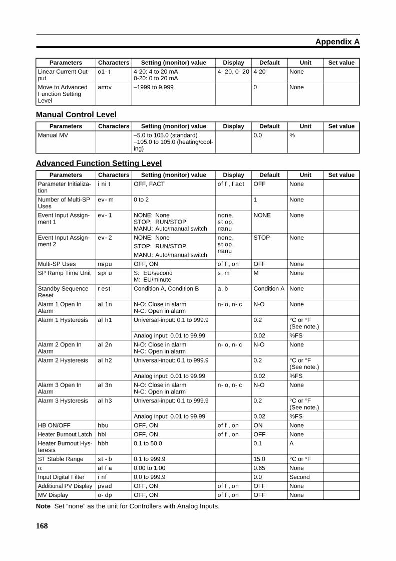
168
Appendix A
Manual Control Level
Advanced Function Setting Level
Linear Current Out-put
o1-t 4-20: 4 to 20 mA0-20: 0 to 20 mA
4-20, 0-20 4-20 None
Move to Advanced Function Setting Level
amov −1999 to 9,999 0 None
Parameters Characters Setting (monitor) value Display Default Unit Set valueManual MV −5.0 to 105.0 (standard)
−105.0 to 105.0 (heating/cool-ing)
0.0 %
Parameters Characters Setting (monitor) value Display Default Unit Set valueParameter Initializa-tion
init OFF, FACT off, fact OFF None
Number of Multi-SP Uses
ev-m 0 to 2 1 None
Event Input Assign-ment 1
ev-1 NONE: NoneSTOP: RUN/STOPMANU: Auto/manual switch
none, stop, manu
NONE None
Event Input Assign-ment 2
ev-2 NONE: NoneSTOP: RUN/STOPMANU: Auto/manual switch
none, stop, manu
STOP None
Multi-SP Uses mspu OFF, ON off, on OFF NoneSP Ramp Time Unit spru S: EU/second
M: EU/minutes, m M None
Standby Sequence Reset
rest Condition A, Condition B a, b Condition A None
Alarm 1 Open In Alarm
al1n N-O: Close in alarmN-C: Open in alarm
n-o, n-c N-O None
Alarm 1 Hysteresis alh1 Universal-input: 0.1 to 999.9 0.2 °C or °F (See note.)
Analog input: 0.01 to 99.99 0.02 %FSAlarm 2 Open In Alarm
al2n N-O: Close in alarmN-C: Open in alarm
n-o, n-c N-O None
Alarm 2 Hysteresis alh2 Universal-input: 0.1 to 999.9 0.2 °C or °F (See note.)
Analog input: 0.01 to 99.99 0.02 %FSAlarm 3 Open In Alarm
al3n N-O: Close in alarmN-C: Open in alarm
n-o, n-c N-O None
Alarm 3 Hysteresis alh3 Universal-input: 0.1 to 999.9 0.2 °C or °F (See note.)
Analog input: 0.01 to 99.99 0.02 %FSHB ON/OFF hbu OFF, ON off, on ON NoneHeater Burnout Latch hbl OFF, ON off, on OFF NoneHeater Burnout Hys-teresis
hbh 0.1 to 50.0 0.1 A
ST Stable Range st-b 0.1 to 999.9 15.0 °C or °Fα alfa 0.00 to 1.00 0.65 NoneInput Digital Filter inf 0.0 to 999.9 0.0 SecondAdditional PV Display pvad OFF, ON off, on OFF NoneMV Display o-dp OFF, ON off, on OFF None
Parameters Characters Setting (monitor) value Display Default Unit Set value
Note Set “none” as the unit for Controllers with Analog Inputs.

169
Appendix A
Automatic Display return Time
ret OFF or 1 to 99 off, 1 to 99
OFF Second
Alarm 1 Latch a1lt OFF, ON off, on OFF NoneAlarm 2 Latch a2lt OFF, ON off, on OFF NoneAlarm 3 Latch a3lt OFF, ON off, on OFF NoneMove to Protect Level Time
prlt 1 to 30 3 Second
Input Error Output sero OFF, ON off, on OFF NoneCold Junction Com-pensation Method
cjc OFF, ON off, on ON None
MB Command Logic Switching
rlrv OFF, ON off, on OFF None
Alarm 1 ON Delay a1on 0 to 999 (0: ON delay dis-abled)
0 Second
Alarm 2 ON Delay a2on 0 to 999 (0: ON delay dis-abled)
0 Second
Alarm 3 ON Delay a3on 0 to 999 (0: ON delay dis-abled)
0 Second
Alarm 1 OFF Delay a1of 0 to 999 (0: OFF delay dis-abled)
0 Second
Alarm 2 OFF Delay a2of 0 to 999 (0: OFF delay dis-abled)
0 Second
Alarm 3 OFF Delay a3of 0 to 999 (0: OFF delay dis-abled)
0 Second
Input Shift Type istp INS1: Temperature input 1-point shift
INS2: Temperature input 2-point shift
ins1, ins2 INS1 None
Auto/Manual Select Addition
amad OFF, ON off, on OFF None
HS Alarm Use hsu OFF, ON off, on ON NoneHS Alarm Latch hsl OFF, ON off, on OFF NoneHS Alarm Hysteresis hsh 0.1 to 50.0 0.1 ALBA Detection Time lba 0 to 9999 (0: LBA function dis-
abled)0 Second
LBA Level lbal Universal-input: 0.1 to 999.9 8.0 °C or °F (See note.)
Analog input: 0.01 to 99.99 10.00 %FSLBA Band lbab Universal-input: 0.0 to 999.9 3.0 °C or °F
(See note.)Analog input: 0.00 to 99.99 0.20 %FS
Parameters Characters Setting (monitor) value Display Default Unit Set value
Note Set “none” as the unit for Controllers with Analog Inputs.
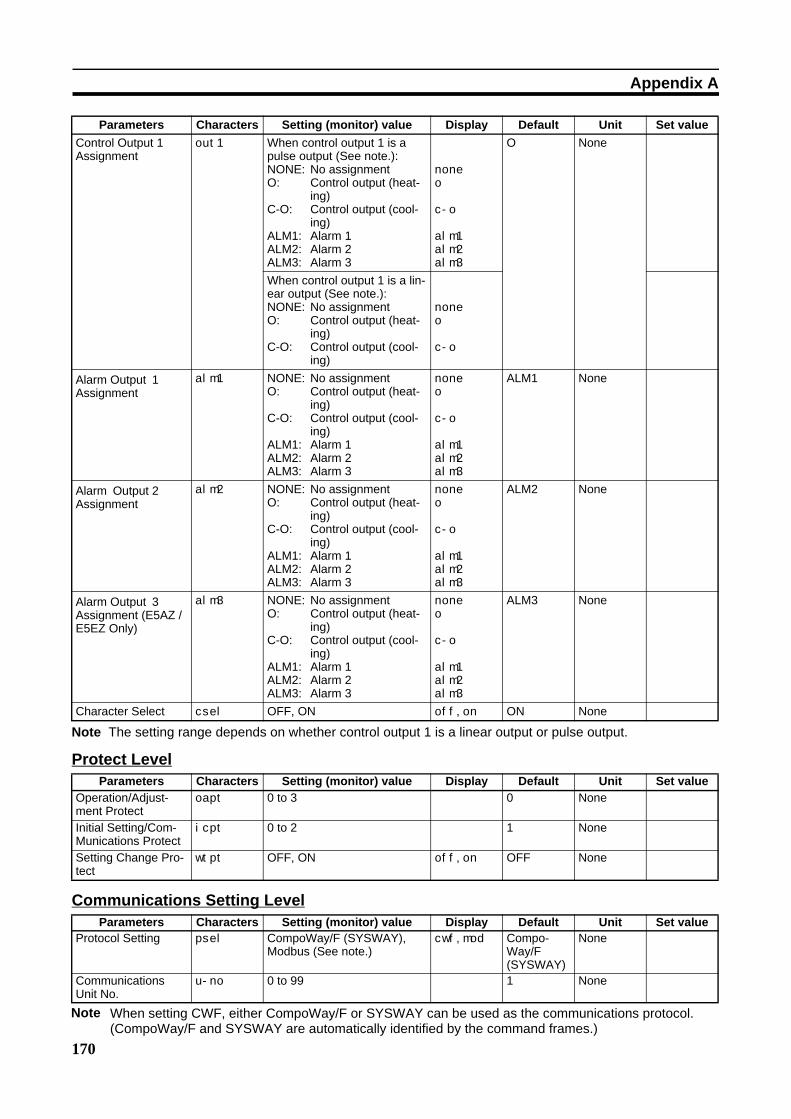
170
Appendix A
Protect Level
Communications Setting Level
Control Output 1 Assignment
out1 When control output 1 is a pulse output (See note.):NONE: No assignmentO: Control output (heat-
ing)C-O: Control output (cool-
ing)ALM1: Alarm 1ALM2: Alarm 2ALM3: Alarm 3
none
o
c-o
alm1
alm2
alm3
O None
When control output 1 is a lin-ear output (See note.):NONE: No assignmentO: Control output (heat-
ing)C-O: Control output (cool-
ing)
none
o
c-o
Alarm Output 1 Assignment
alm1 NONE: No assignmentO: Control output (heat-
ing)C-O: Control output (cool-
ing)ALM1: Alarm 1ALM2: Alarm 2ALM3: Alarm 3
none
o
c-o
alm1
alm2
alm3
ALM1 None
Alarm Output 2 Assignment
alm2 NONE: No assignmentO: Control output (heat-
ing)C-O: Control output (cool-
ing)ALM1: Alarm 1ALM2: Alarm 2ALM3: Alarm 3
none
o
c-o
alm1
alm2
alm3
ALM2 None
Alarm Output 3 Assignment (E5AZ /E5EZ Only)
alm3 NONE: No assignmentO: Control output (heat-
ing)C-O: Control output (cool-
ing)ALM1: Alarm 1ALM2: Alarm 2ALM3: Alarm 3
none
o
c-o
alm1
alm2
alm3
ALM3 None
Character Select csel OFF, ON off, on ON None
Parameters Characters Setting (monitor) value Display Default Unit Set valueOperation/Adjust-ment Protect
oapt 0 to 3 0 None
Initial Setting/Com-Munications Protect
icpt 0 to 2 1 None
Setting Change Pro-tect
wtpt OFF, ON off, on OFF None
Parameters Characters Setting (monitor) value Display Default Unit Set valueProtocol Setting psel CompoWay/F (SYSWAY),
Modbus (See note.)cwf, mod Compo-
Way/F (SYSWAY)
None
Communications Unit No.
u-no 0 to 99 1 None
Parameters Characters Setting (monitor) value Display Default Unit Set value
Note The setting range depends on whether control output 1 is a linear output or pulse output.
When setting CWF, either CompoWay/F or SYSWAY can be used as the communications protocol. (CompoWay/F and SYSWAY are automatically identified by the command frames.)
Note
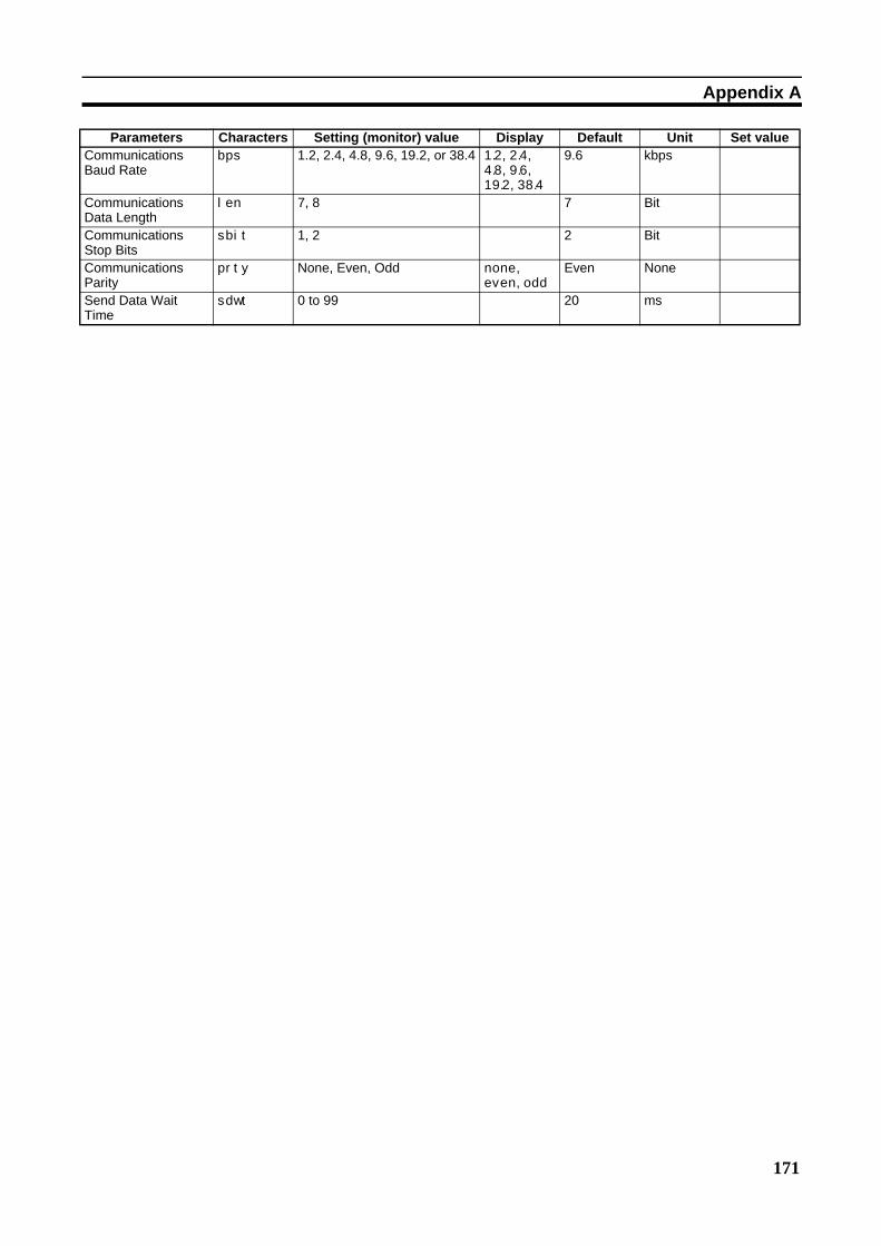
171
Appendix A
Communications Baud Rate
bps 1.2, 2.4, 4.8, 9.6, 19.2, or 38.4 1.2, 2.4, 4.8, 9.6, 19.2, 38.4
9.6 kbps
Communications Data Length
len 7, 8 7 Bit
Communications Stop Bits
sbit 1, 2 2 Bit
Communications Parity
prty None, Even, Odd none, even, odd
Even None
Send Data Wait Time
sdwt 0 to 99 20 ms
Parameters Characters Setting (monitor) value Display Default Unit Set value
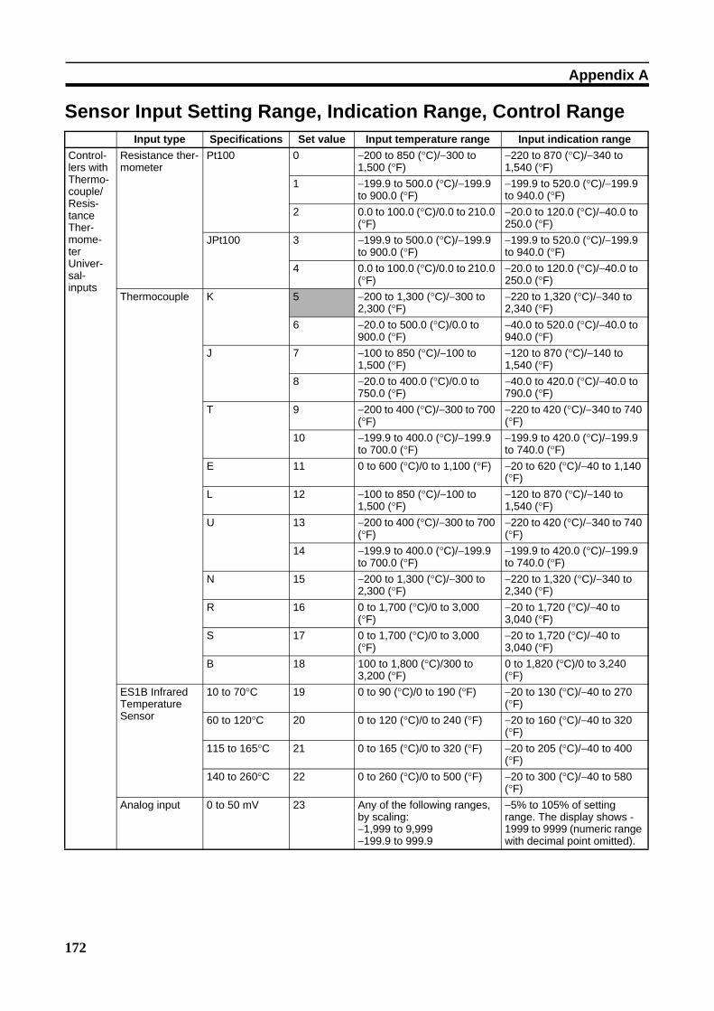
172
Appendix A
Sensor Input Setting Range, Indication Range, Control RangeInput type Specifications Set value Input temperature range Input indication range
Control-lers with Thermo-couple/Resis-tance Ther-mome-ter Univer-sal-inputs
Resistance ther-mometer
Pt100 0 −200 to 850 (°C)/−300 to 1,500 (°F)
−220 to 870 (°C)/−340 to 1,540 (°F)
1 −199.9 to 500.0 (°C)/−199.9 to 900.0 (°F)
−199.9 to 520.0 (°C)/−199.9 to 940.0 (°F)
2 0.0 to 100.0 (°C)/0.0 to 210.0 (°F)
−20.0 to 120.0 (°C)/−40.0 to 250.0 (°F)
JPt100 3 −199.9 to 500.0 (°C)/−199.9 to 900.0 (°F)
−199.9 to 520.0 (°C)/−199.9 to 940.0 (°F)
4 0.0 to 100.0 (°C)/0.0 to 210.0 (°F)
−20.0 to 120.0 (°C)/−40.0 to 250.0 (°F)
Thermocouple K 5 −200 to 1,300 (°C)/−300 to 2,300 (°F)
−220 to 1,320 (°C)/−340 to 2,340 (°F)
6 −20.0 to 500.0 (°C)/0.0 to 900.0 (°F)
−40.0 to 520.0 (°C)/−40.0 to 940.0 (°F)
J 7 −100 to 850 (°C)/−100 to 1,500 (°F)
−120 to 870 (°C)/−140 to 1,540 (°F)
8 −20.0 to 400.0 (°C)/0.0 to 750.0 (°F)
−40.0 to 420.0 (°C)/−40.0 to 790.0 (°F)
T 9 −200 to 400 (°C)/−300 to 700 (°F)
−220 to 420 (°C)/−340 to 740 (°F)
10 −199.9 to 400.0 (°C)/−199.9 to 700.0 (°F)
−199.9 to 420.0 (°C)/−199.9 to 740.0 (°F)
E 11 0 to 600 (°C)/0 to 1,100 (°F) −20 to 620 (°C)/−40 to 1,140 (°F)
L 12 −100 to 850 (°C)/−100 to 1,500 (°F)
−120 to 870 (°C)/−140 to 1,540 (°F)
U 13 −200 to 400 (°C)/−300 to 700 (°F)
−220 to 420 (°C)/−340 to 740 (°F)
14 −199.9 to 400.0 (°C)/−199.9 to 700.0 (°F)
−199.9 to 420.0 (°C)/−199.9 to 740.0 (°F)
N 15 −200 to 1,300 (°C)/−300 to 2,300 (°F)
−220 to 1,320 (°C)/−340 to 2,340 (°F)
R 16 0 to 1,700 (°C)/0 to 3,000 (°F)
−20 to 1,720 (°C)/−40 to 3,040 (°F)
S 17 0 to 1,700 (°C)/0 to 3,000 (°F)
−20 to 1,720 (°C)/−40 to 3,040 (°F)
B 18 100 to 1,800 (°C)/300 to 3,200 (°F)
0 to 1,820 (°C)/0 to 3,240 (°F)
ES1B Infrared Temperature Sensor
10 to 70°C 19 0 to 90 (°C)/0 to 190 (°F) −20 to 130 (°C)/−40 to 270 (°F)
60 to 120°C 20 0 to 120 (°C)/0 to 240 (°F) −20 to 160 (°C)/−40 to 320 (°F)
115 to 165°C 21 0 to 165 (°C)/0 to 320 (°F) −20 to 205 (°C)/−40 to 400 (°F)
140 to 260°C 22 0 to 260 (°C)/0 to 500 (°F) −20 to 300 (°C)/−40 to 580 (°F)
Analog input 0 to 50 mV 23 Any of the following ranges, by scaling:−1,999 to 9,999−199.9 to 999.9
−5% to 105% of setting range. The display shows -1999 to 9999 (numeric range with decimal point omitted).
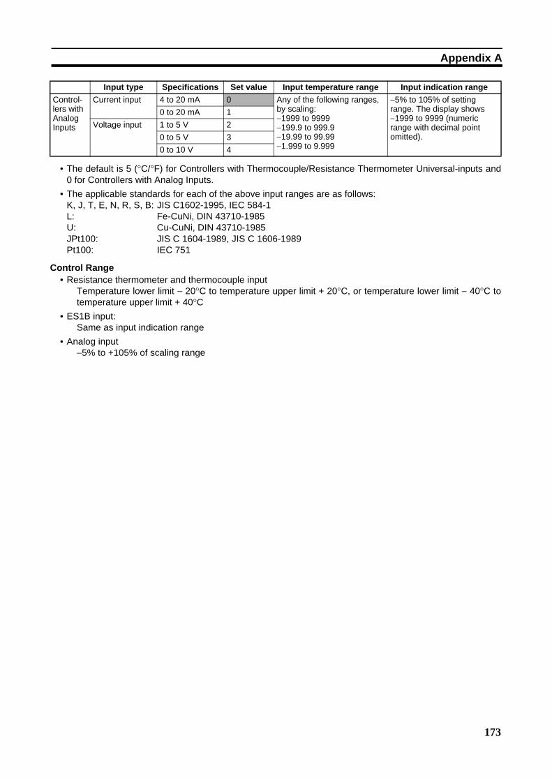
173
Appendix A
• The default is 5 (°C/°F) for Controllers with Thermocouple/Resistance Thermometer Universal-inputs and0 for Controllers with Analog Inputs.
• The applicable standards for each of the above input ranges are as follows:K, J, T, E, N, R, S, B: JIS C1602-1995, IEC 584-1L: Fe-CuNi, DIN 43710-1985U: Cu-CuNi, DIN 43710-1985JPt100: JIS C 1604-1989, JIS C 1606-1989Pt100: IEC 751
Control Range• Resistance thermometer and thermocouple input
Temperature lower limit − 20°C to temperature upper limit + 20°C, or temperature lower limit − 40°C totemperature upper limit + 40°C
• ES1B input:Same as input indication range
• Analog input−5% to +105% of scaling range
Control-lers with Analog Inputs
Current input 4 to 20 mA 0 Any of the following ranges, by scaling:−1999 to 9999−199.9 to 999.9−19.99 to 99.99−1.999 to 9.999
−5% to 105% of setting range. The display shows −1999 to 9999 (numeric range with decimal point omitted).
0 to 20 mA 1Voltage input 1 to 5 V 2
0 to 5 V 30 to 10 V 4
Input type Specifications Set value Input temperature range Input indication range
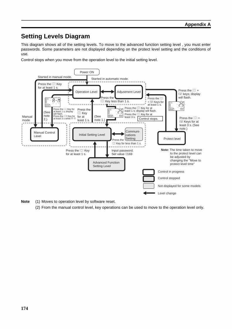
174
Appendix A
Setting Levels DiagramThis diagram shows all of the setting levels. To move to the advanced function setting level , you must enterpasswords. Some parameters are not displayed depending on the protect level setting and the conditions ofuse.Control stops when you move from the operation level to the initial setting level.
Note (1) Moves to operation level by software reset.(2) From the manual control level, key operations can be used to move to the operation level only.
(See note 2.)
(See note 1.)
Power ON
Started in manual mode.
Manual mode
Press the O Key for at least 1 s.
Press the O Key for at least 1 s; display will flash.Press the Ol Key for at least 3 s while a-m
Manual Control Level
Operation Level
Press the O Key for at least 1 s.
Initial Setting Level
Press the O Key for at least 1 s.
Advanced Function Setting Level
Input password. Set value −169
Press the O Key less than 1 s.
Communi-cations Setting
Press the O Key for at least 1 s; display will flash.Press the O Key for at least 3 s. Control stops.
Press the O Key for less than 1 s.
Adjustment Level
Press the O + M Keys for at least 1 s.
Press the O + M keys; display will flash.
Press the O + M Keys for at least 3 s. (See note.)
Protect level
Note: The time taken to move to the protect level can be adjusted by changing the "Move to protect level time"
Control in progress
Level change
Not displayed for some models
Control stopped
Started in automatic mode.
a-mC
25100
C
25100
C
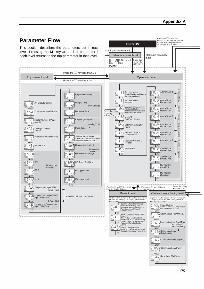
175
Appendix A
M
M
M
M
M
M
M
M
M
M
M
M
M
M
M
M
M
M
M
a-mP
m-sp0
P
25C
250
C
sp-m0
C
ct10.0
P
lcr10.0
P
r-srun
P
al-10
C
al1h0
C
al1l0
C
al-20
C
al2h0
C
al2l0
C
al-30
C
al3h0
C
al3l0
C
o0.0
P
c-o0.0
P
M
M
M
M
M
M
M
M
M
M
M
M
M
M
M
M
M
M
M
M
M
M
M
cmwtoff
ct10.0
P
atoff
P
lcr10.0
P
hb10.0
P
hs150.0
P
sp-00
C
sp-10
C
sp-20
C
sp-30
C
ins0.0
C
insh0.0
C
p8.0
C
i233
P
d40
P
c-sc1.00
P
c-db0.0
C
of-r50.0
P
hys1.0
C
chys1.0
C
sprtoff
C
ol-h105.0
P
ol-l-5.0
P
M
M
M
M
M
M
M
pselcwf
u-no1
bps9.6
len7
sbit2
prtyeven
sdwt20
M
M
M
oapt0
P
icpt1
P
wtptoff
P
25C
M
insl0.0
C
Power ON
Starting in manual mode.
Manual control level
PID control only
PV/MV
Press the O Key for at least 1 s
Press the O Key for at least 3 s. Displays other than that for switching between automatic and manual.
Adjustment LevelPress the O Key less than 1 s.
Press the O Key less than 1 s.
Operation Level
AT Execute/Cancel
Communications Writing
Heater Current 1 Value Monitor
Leakage Current 1 Monitor
HS Alarm 1
Heater Burnout Detection 1
SP 0
SP 3
SP 2
SP1SP Used By Multi-SP
Temperature Input Shift1-Point Shift
Set either of these parameters.Upper-Limit Temperature Input Shift Value
2-Point Shift
Lower-Limit Temperature Input Shift Value
Proportional Band
Integral Time
PID Settings
Derivative Time
Cooling Coefficient
Heating/Cooling
Dead Band
Manual Reset ValueClear the Offset During Stabil- ization of P or PD Control.
Hysteresis (Heating)
Hysteresis Settings
Hysteresis (Cooling)
SP Ramp Set Value
MV Upper Limit
MV Lower Limit
Process ValueAdded When Additional PV Display is ON.
Auto/Manual SwitchPID Control Only.Added When Auto/Manual Select Addition is ON.
Press the O Key forat least 3 s.
Multi-SP Set Point Setting
Heater Current 1 Value Monitor
Leakage Current 1 Monitor
RUN/STOP
Alarm Value 1
Set
eith
er o
f the
se p
aram
eter
s.S
et e
ither
of t
hese
par
amet
ers.
Set
eith
er o
f the
se p
aram
eter
s.
Alarm Value Upper Limit 1
Alarm Value Lower Limit 1
Alarm Value 2
Alarm Value Upper Limit 2
Alarm Value Lower Limit 2
Alarm Value 3
Alarm Value Upper Limit 3
Alarm Value Lower Limit 3
MV Monitor (Heating)
MV Monitor (Cooling)
Press the O and M Keys for at least 3 s. Display flashess.
Press the O and M Keys for at least 1 s.
Press the O Keyless than 1 s
Protect Level Communications Setting Level
The time taken to move to the protect level can be adjusted by changing the "Move to protect level time" setting.
Starting in automatic mode.
Process value/ set point
Displayed only for models with communications. Changes are effective after cycling power or after a software reset.
Operation/Adjustment ProtectRestricts Displaying And Modifying Menus In Operation, Adjustment, And Manual Control Levels.
Initial Setting/Communications ProtectThis Protect Level Restricts Movement To The Initial Setting, Communications Setting, And Advanced Function Setting Levels.
Setting Change ProtectProtects Changes To Setups By Operating The Front Panel Keys.
Protocol SettingSwitches Between CompoWay/F (SYSWAY) And Modbus.
Communications Unit No.
Communications Baud RateCompoWay/F (SYSWAY) Only
Communications Stop Bits
Communications Parity
Send Data Wait Time
Set Point During SP Ramp
Communications Data Length
Parameter FlowThis section describes the parameters set in eachlevel. Pressing the M key at the last parameter ineach level returns to the top parameter in that level.
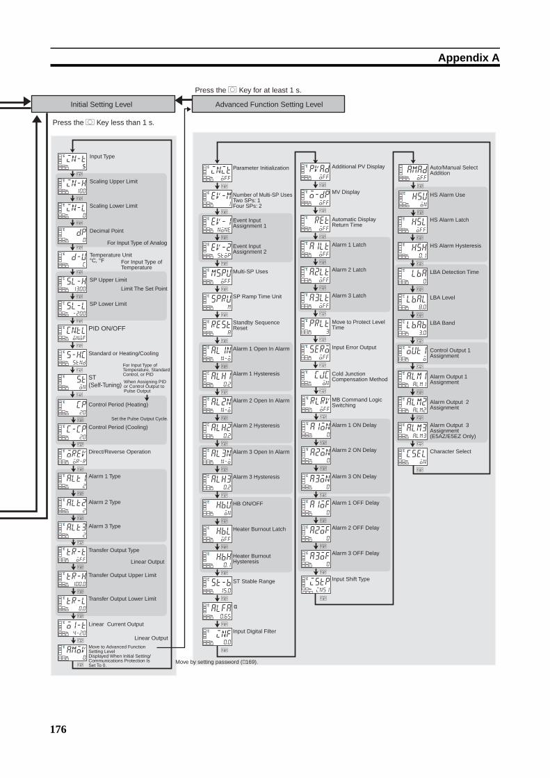
176
Appendix A
M
M
M
M
M
M
M
M
M
M
M
M
M
M
M
M
M
M
M
M
M
in-l0
P
dp0
P
in-t5
P
in-h100
P
d-uc
P
sl-h1300
C
sl-l-200
C
cntlonof
P
s-hcstnd
P
ston
P
cp20
P
c-cp20
P
oreVor-r
P
alt12
P
alt22
P
alt32
P
tr-toff
P
tr-h100.0
P
tr-l0.0
P
o1-t4-20
P
amov0
P
PID ON/OFF
ST (Self-Tuning)
M
M
M
M
M
M
M
M
M
M
M
M
M
M
M
M
M
M
M
M
M
M
M
M
M
M
M
M
M
M
M
M
M
M
M
M
M
M
M
M
M
M
M
M
M
M
initoff
P
ev-m1
P
ev-1none
P
ev-2stop
P
mspuoff
P
sprum
P
resta
P
al1nn-o
P
alh10.2
C
al2nn-o
P
alh20.2
C
al3nn-o
P
alh30.2
C
hbuon
P
hbloff
P
hbh0.1
P
st-b15.0
C
alfa0.65
P
inf0.0
P
pvadoff
P
o-dpoff
P
retoff
P
a1ltoff
P
a2ltoff
P
a3ltoff
P
prlt3
P
serooff
P
cjcon
P
rlrvoff
P
a1on0
P
a2on0
P
a3on0
P
a1of0
P
a2of0
P
a3of0
P
istpins1
P
amadoff
hsuon
P
hsloff
P
hsh0.1
P
lba0
P
lbal8.0
C
lbab3.0
C
out1o
P
alm1alm1
P
alm2alm2
P
α
Initial Setting Level Advanced Function Setting Level
Press the O Key for at least 1 s.
Press the O Key less than 1 s.
Input Type
Scaling Upper Limit
Scaling Lower Limit
Decimal Point
For Input Type of Analog
Temperature Unit°C, °F For Input Type of
Temperature
SP Upper Limit
SP Lower Limit
Standard or Heating/Cooling
For Input Type of Temperature, Standard Control, or PID
When Assigning PID or Control Output to Pulse Output
Control Period (Heating)
Set the Pulse Output Cycle.
Control Period (Cooling)
Direct/Reverse Operation
Alarm 1 Type
Alarm 3 Type
Alarm 2 Type
Transfer Output Type
Linear Output
Transfer Output Upper Limit
Transfer Output Lower Limit
Linear Current Output
Linear Output
Move to Advanced Function Setting LevelDisplayed When Initial Setting/ Communications Protection Is Set To 0.
Move by setting password (−169).
Parameter Initialization
Number of Multi-SP UsesTwo SPs: 1Four SPs: 2
Event Input Assignment 1
Event Input Assignment 2
Multi-SP Uses
SP Ramp Time Unit
Standby Sequence Reset
Alarm 1 Open In Alarm
Alarm 1 Hysteresis
Alarm 2 Open In Alarm
Alarm 2 Hysteresis
Alarm 3 Open In Alarm
Alarm 3 Hysteresis
Heater Burnout Latch
HB ON/OFF
Heater Burnout Hysteresis
ST Stable Range
Input Digital Filter
Additional PV Display
MV Display
Automatic Display Return Time
Alarm 1 Latch
Alarm 3 Latch
Alarm 2 Latch
Move to Protect Level Time
Input Error Output
Cold Junction Compensation Method
MB Command Logic Switching
Alarm 1 ON Delay
Alarm 3 ON Delay
Alarm 2 ON Delay
Alarm 1 OFF Delay
Alarm 3 OFF Delay
Alarm 2 OFF Delay
Input Shift Type
Auto/Manual Select Addition
HS Alarm Use
HS Alarm Latch
HS Alarm Hysteresis
LBA Detection Time
LBA Level
LBA Band
Control Output 1 Assignment
Alarm Output 1 Assignment
Alarm Output 2 Assignment
M
cselon
P Character Select
Limit The Set Point
M
alm3alm3
P Alarm Output 3 Assignment (E5AZ/E5EZ Only)
177
Index
Numerics2-PID control, 36, 122
Aadjustment level, 11, 106
parameter operation lists, 164
advanced function setting level, 11, 129
moving to, 76, 128
parameter operation lists, 167
alarm delays, 79
alarms, 9alarm output 1 assignment, 146
alarm output 2 assignment, 147
alarm output 3 assignment, 148
alarm delays, 79
alarm hysteresis, 63
alarm latch, 63
alarm outputs 1, 2 and 3
wiring, 24
alarm types, 47
alarm values, 49
operation, 64
analog input, 8, 65
AT (auto-tuning), 43
AT execute/cancel, 43
auto control, 72
auto/manual select addition, 86, 143
auto/manual switch, 99
Bbasic model
E5AZ, 7E5CZ, 5E5CZ-U, 6E5EZ, 7
Ccharacteristics, 152
close in alarm, 64
wiring
RS-232C, 27
RS-485, 26
communications function, 9
communications setting level, 12, 149
parameter operation lists, 169
control outputs, 9, 38
control outputs 1
wiring, 23
control periods, 36, 124
cooling coefficient
setting, 68
current transformer
calculating detection current values, 51
Current Transformers (CT), 51, 153
CT inputs
wiring, 25
external dimensions, 154
E54-CT1, 154
E54-CT3, 154
specifications, 153
Current Value Exceeds (error display), 158
Ddead band, 67
setting, 68
derivative time, 46
detection current, 51
dimensions, 16
E5AZ, 16
E5CZ, 16
E5CZ-U, 16
E5EZ, 17
direct operation, 37, 124
Display Range Exceeded (error display), 156
down key, 4
Eerror displays, 156
Current Value Exceeds, 158
Display Range Exceeded, 156
HB Error, 157
Heater Burnout, 158
HS Alarm, 158
Input Error, 156
Memory Error, 157
ESIB, 60
event inputs, 9, 25, 69
wiring, 25
external dimensions

178
Index
Current Transformer (CT), 153
Ffront panel
E5AZ, 2E5CZ, 2E5CZ-U, 2E5EZ, 3
HHB Error (error display), 157
HB alarm (heater burnout alarm), 50
settings, 53
Heater Burnout (error display), 158
heater burnout alarm, 9, 136, 152
heater burnout hysteresis, 136
heating/cooling control, 66, 113, 116, 123
cooling coefficient, 67, 113
dead band, 67, 114
setting, 68
HS alarm, 9, 50, 152
settings, 55
HS Alarm (error display), 158
hysteresis, 41, 42
II/O configuration, 5
basic model
E5AZ, 7E5CZ, 5E5CZ-U, 6E5EZ, 7
main functions, 8indicators
meanings, 3operation, 3
initial setting level, 11, 118
parameter operation lists, 165
initial setting/communications protect, 78
initial settings, 32
examples, 32, 33
initialization, 130
Input Error (error display), 156
input sensor types, 8, 119
input shift, 59
one-point shift, 59
two-point shift, 60
calculating, 60
input types, 34
default values, 173
list, 35
setting, 34
inputs
wiring, 23
installation, 16, 18
E5AZ/E5EZ
mounting the terminal cover, 19
mounting to the panel, 19
E5CZ/E5CZ-U
mounting the terminal cover, 18
mounting to the panel, 19
panel cutout
E5AZ, 17
E5CZ, 17
E5CZ-U, 17
E5EZ, 18
removing from case
E5AZ, 20
E5CZ, 20
E5EZ, 20
integral time, 46
Kkeys
down key, 4key operations, 10
level key, 4mode key, 4operations, 4up key, 4
LLBA (loop break alarm), 81
band, 83
detection time, 82
level, 82, 83
level key, 4loop break alarm (LBA), 81
Mmain functions, 8

Index
179
manual control, 72, 84
manual control level, 11
moving to, 85
parameter operation lists, 167
manual setup, 46
Memory Error (error display), 157
mode key, 4mounting, 18
terminal cover
E5AZ/E5EZ, 19
E5CZ/E5CZ-U, 18
to panel
E5AZ/E5EZ, 19
E5CZ/E5CZ-U, 19
multi-SP, 69, 99, 131
NNo. 1 display, 3No. 2 display, 3
OON/OFF control, 36, 122
setting, 41
one-point shift, 61
open in alarm, 64
operation level, 11, 97
parameter operation lists, 163
operation/adjustment protect, 78
output functions
assignments, 38
output limits, 91
output specifications
setting, 36
Ppanel cutout
E5AZ, 17
E5CZ/E5CZ-U, 17
E5EZ, 18
parameter flow, 175
parameter operation list, 163
adjustment level, 164
manual control level, 67
operation level, 163
parameter operation lists
advanced function setting level, 167
communications setting level, 169
initial setting level, 165
protect level, 169
parameters
additional PV display, 138
alarm output 1 assignment, 146
alarm 1 hysteresis, 135
alarm 1 latch, 139
alarm 1 OFF delay, 142
alarm 1 ON delay, 141
alarm 1 open in alarm, 134
alarm 1 type, 124
alarm output 2 assignment, 147
alarm 2 hysteresis, 135
alarm 2 latch, 139
alarm 2 OFF delay, 142
alarm 2 ON delay, 141
alarm 2 open in alarm, 134
alarm 2 type, 126
alarm output 3 assignment, 148
alarm 3 hysteresis, 135
alarm 3 latch, 139
alarm 3 OFF delay, 142
alarm 3 ON delay, 141
alarm 3 open in alarm, 134
alarm 3 type, 126
alarm value 1, 101
alarm value 2, 102
alarm value 3, 102
alarm value lower limit 1, 103
alarm value lower limit 2, 103
alarm value lower limit 3, 104
alarm value upper limit 1, 103
alarm value upper limit 2, 103
alarm value upper limit 3, 104
alpha, 137
AT execute/cancel, 108
auto/manual select addition, 143
auto/manual switch, 99
automatic display return time, 139
character select, 148
cold junction compensation method, 140
communications baud rate, 149
communications data length, 149
communications parity, 149
communications stop bits, 149
communications Unit No., 149
communications writing, 108
control output 1 assignment, 146
control period (cooling), 124
control period (heating), 124

180
Index
cooling coefficient, 113
dead band, 114
decimal point, 121
derivative time, 113
direct/reverse operation, 124
event input assignment 1, 132
event input assignment 2, 132
HB ON/OFF, 135
heater burnout detection 1, 110
heater burnout hysteresis, 136
heater burnout latch, 136
heater current 1 value monitor, 100, 109
HS alarm 1, 110
HS alarm latch, 143
hysteresis (cooling), 114
hysteresis (heating), 114
initial setting/communications protect, 96
input digital filter, 138
input error output, 140
input shift type, 142
input type, 119
integral time, 113
LBA band, 145
LBA detection time, 144
LBA level, 145
leakage current 1 monitor, 101, 109
lower-limit temperature input shift value, 112
manual reset value, 114
MB command logic switching, 141
move to advanced function setting level, 128
move to protect level time, 140
multi-SP set point setting, 99
multi-SP uses, 132
MV (manual MV), 117
MV display, 138
MV lower limit, 116
MV monitor (cooling), 105
MV monitor (heating), 104
MV upper limit, 116
number of multi-SP uses, 131
operation/adjustment protect, 96
parameter initialization, 130
PID ON/OFF, 122
process value, 98
process value/set point, 99
proportional band, 113
protocol setting, 149
PV/MV (manual MV), 117
RUN/STOP, 101
scaling lower limit, 121
scaling upper limit, 121
selecting, 12
send data wait time, 149
set point during SP ramp, 100
setting change protect, 96
SP 0, 111
SP 1, 111
SP 2, 111
SP 3, 111
SP lower limit, 122
SP ramp set value, 116
SP ramp time unit, 132
SP upper limit, 122
ST (self-tuning), 123
ST stable range, 137
standard or heating/cooling, 123
standby sequence reset, 133
temperature input shift, 111
temperature unit, 121
transfer output lower limit, 127
transfer output type, 127
transfer output upper limit, 127
upper-limit temperature input shift value, 112
part names
functions, 2PID constants, 43, 44
setting manually, 46
PID control
setting, 41
power supply
wiring, 22
precautions
wiring, 22
process value (PV), 98
proportional action, 46
proportional band, 46
protect level, 11, 77, 95
moving to, 140
parameter operation lists, 169
protection, 77
initial setting/communications, 78, 96
operation/adjustment, 78, 96
setting change, 78, 96
PV/MV, 117
Rratings, 151
removing from case
E5AZ/E5EZ, 20
E5CZ, 20
Index
181
reverse operation, 37, 124
run/stop control, 72
Sscaling
upper and lower limits for analog inputs, 65
self-tuning (ST), 44, 123
sensor input
control range, 172
indication range, 172
setting range, 172
sensor types, 119
set point (SP), 40
limiter, 73
limiting change rate, 74
lower limit, 74
ramp, 74
setting, 40, 41
setting upper and lower limits, 73
switching between SPs, 71
upper limit, 73
setting change protect, 78
setting level configuration, 10
setting levels
diagram, 174
settings
cooling coefficient, 68
dead band, 68
event input, 69
fixing, 12
HB alarm (heater burnout alarm), 53
moving to advanced function setting level, 53
heating/cooling control, 68
HS alarm, 55
moving to advanced function setting level, 54
hysteresis, 42
LBA detection time, 82
PID ON/OFF, 41
SP lower limit, 74
SP upper limit, 73
switching between SPs, 72
shifting input values, 59
SP ramp, 74
alarm operations, 76
operation at startup, 75
restrictions, 75
specifications, 151
Current Transformer (CT), 153
output, 36
USB-Serial Conversion Cable, 155
ST (self-tuning), 44
ST stable range, 45
startup conditions, 45
standard control, 123
standby sequence, 63
startup
conditions, 45
operation, 75
support software port, 27
Ttemperature input, 8
shift values, 62
temperature unit, 4, 36
terminals
arrangement
E5AZ/E5EZ, 22
E5CZ, 21
E5CZ-U, 21
wiring, 22
three-position control, 41
transfer output, 88
type, 88
troubleshooting, 158, 159, 160
two-point shift, 60, 62
calculating, 60
Uup key, 4USB-Serial Conversion Cable
specifications, 155
Wwiring, 22
alarm outputs 1, 2, and 3, 24
communications
RS-232C, 27
RS-485, 26
control output 1, 23
CT inputs, 25
event inputs, 25
inputs, 23
power supply, 22

182
Index
precautions, 22
terminal arrangement, 21
terminals, 21

183
Revision History
A manual revision code appears as a suffix to the catalog number on the front cover of the manual.
The following table outlines the changes made to the manual during each revision. Page numbers refer to theprevious version.
Revision code Date Revised content01 September 2008 Original production
Cat. No. H207-E1-01
Revision code