e4codergui reference manual -...
TRANSCRIPT
E4CoderGUI Reference Manual
Rapid User Interface Prototyping for XCos Models
Version: 1.3
May 19, 2015
Scilab version

About Evidence S.r.l.
Evidence is a company operating in the field of software for embedded real-time systems.It started in 2002 as a spin-off company of the Real-Time Systems (ReTiS) Lab of theScuola Superiore Sant’Anna (Pisa, Italy). Today, Evidence is a dynamic company havingcollaborations in the field of electronics, telecommunications, automotives, and industrialautomation.
People at Evidence are experts in the domain of embedded and real-time systems, witha deep knowledge on the design and specification flow of embedded software, especiallyfor the embedded market.
Besides providing consultancy services, Evidence also provides: BSPs based on Linuxfor embedded devices, evaluation boards featuring most innovative 8, 16 and 32-bitmicrocontrollers for the embedded market, development tools for making embeddedsoftware development easier, and tools for the schedulability analysis of real-time tasksrunning on your final product.
For more information see: http://www.evidence.eu.com
Contact Info
Evidence Srl,Via Carducci 56Localita Ghezzano56010 S.Giuliano TermePISA Italy
Tel: +39 050 99 11 224Fax: +39 050 99 10 812
For more information about Evidence products, please send an e-mail to the follow-ing address: [email protected]. Other information about the Evidence productline can be found at the Evidence web site at: http://www.evidence.eu.com.
This document is Copyright 2011-2015 Evidence S.r.l.
Information and images contained within this document are copyright and the property of Evidence
S.r.l. All trademarks are hereby acknowledged to be the properties of their respective owners. The
information, text and graphics contained in this document are provided for information purposes only by
Evidence S.r.l. Evidence S.r.l. does not warrant the accuracy, or completeness of the information, text,
and other items contained in this document. Matlab, Simulink, Mathworks are registered trademarks
of Matworks Inc. Microsoft, Windows are registered trademarks of Microsoft Inc. Java is a registered
trademark of Sun Microsystems. in the USA. and other countries, and are used under license. All other
trademarks used are properties of their respective owners. This document has been written using LATEX
and LYX.
2
Contents
1. Introduction 101.1. Quick feature list . . . . . . . . . . . . . . . . . . . . . . . . . . . . . . . 101.2. Requirements . . . . . . . . . . . . . . . . . . . . . . . . . . . . . . . . . 101.3. Licensing . . . . . . . . . . . . . . . . . . . . . . . . . . . . . . . . . . . . 101.4. Installation . . . . . . . . . . . . . . . . . . . . . . . . . . . . . . . . . . 111.5. Technical support . . . . . . . . . . . . . . . . . . . . . . . . . . . . . . . 11
2. Use Cases 122.1. Rapid Prototyping . . . . . . . . . . . . . . . . . . . . . . . . . . . . . . 122.2. Simulation . . . . . . . . . . . . . . . . . . . . . . . . . . . . . . . . . . . 12
3. Quick Start 133.1. Creating a New Diagram . . . . . . . . . . . . . . . . . . . . . . . . . . . 133.2. Designing the User Interface . . . . . . . . . . . . . . . . . . . . . . . . . 163.3. Laying out the XCos Diagram . . . . . . . . . . . . . . . . . . . . . . . . 203.4. Simulation . . . . . . . . . . . . . . . . . . . . . . . . . . . . . . . . . . . 24
4. Integration with XCos 274.1. Simulation of a User Interface . . . . . . . . . . . . . . . . . . . . . . . . 28
5. The E4CoderGUI Editor 295.1. Frame and Elements . . . . . . . . . . . . . . . . . . . . . . . . . . . . . 305.2. Properties . . . . . . . . . . . . . . . . . . . . . . . . . . . . . . . . . . . 325.3. Managing Ports . . . . . . . . . . . . . . . . . . . . . . . . . . . . . . . . 33
5.3.1. Connections . . . . . . . . . . . . . . . . . . . . . . . . . . . . . . 355.4. Menus . . . . . . . . . . . . . . . . . . . . . . . . . . . . . . . . . . . . . 355.5. Interface Elements . . . . . . . . . . . . . . . . . . . . . . . . . . . . . . 37
5.5.1. Button . . . . . . . . . . . . . . . . . . . . . . . . . . . . . . . . . 375.5.2. Button Image . . . . . . . . . . . . . . . . . . . . . . . . . . . . . 375.5.3. Button Knob . . . . . . . . . . . . . . . . . . . . . . . . . . . . . 375.5.4. Button LED . . . . . . . . . . . . . . . . . . . . . . . . . . . . . . 385.5.5. Color Bar . . . . . . . . . . . . . . . . . . . . . . . . . . . . . . . 385.5.6. Image . . . . . . . . . . . . . . . . . . . . . . . . . . . . . . . . . 395.5.7. Needle . . . . . . . . . . . . . . . . . . . . . . . . . . . . . . . . . 395.5.8. Plot . . . . . . . . . . . . . . . . . . . . . . . . . . . . . . . . . . 405.5.9. Plotter 2D . . . . . . . . . . . . . . . . . . . . . . . . . . . . . . . 405.5.10. Rectangle . . . . . . . . . . . . . . . . . . . . . . . . . . . . . . . 41
3

Contents
5.5.11. Roller and Slider . . . . . . . . . . . . . . . . . . . . . . . . . . . 415.5.12. SpinBox . . . . . . . . . . . . . . . . . . . . . . . . . . . . . . . . 425.5.13. Switch . . . . . . . . . . . . . . . . . . . . . . . . . . . . . . . . . 425.5.14. Text Label . . . . . . . . . . . . . . . . . . . . . . . . . . . . . . . 435.5.15. Tracker 2D . . . . . . . . . . . . . . . . . . . . . . . . . . . . . . 43
6. Examples 446.1. Dashboard . . . . . . . . . . . . . . . . . . . . . . . . . . . . . . . . . . . 446.2. Plotting . . . . . . . . . . . . . . . . . . . . . . . . . . . . . . . . . . . . 466.3. Integers . . . . . . . . . . . . . . . . . . . . . . . . . . . . . . . . . . . . 48
A. QT Libraries Licensing 49
4

List of Figures
2.1. A user interface used for rapid prototyping. . . . . . . . . . . . . . . . . 12
3.1. The Scilab console at startup. E4Coder is automatically loaded. . . . . . 133.2. Commands to launch XCos with a new diagram. . . . . . . . . . . . . . . 143.3. Message warning that the specified file does not exist and will be created
upon save. . . . . . . . . . . . . . . . . . . . . . . . . . . . . . . . . . . 143.4. The menu item to access the Palette Tree, containing all the blocks that
can be added to a diagram. . . . . . . . . . . . . . . . . . . . . . . . . . 153.5. An item from the Palettes window can be dragged into the diagram to
create a new block. . . . . . . . . . . . . . . . . . . . . . . . . . . . . . . 153.6. In order to set the name of the GUI file for a block, double-click on it,
choose Properties (a), and then type the file name (b). . . . . . . . . . 163.7. The system will report that tutorial.xml does not exist. . . . . . . . . 163.8. The Name property of the Frame is used to set the title of the user interface
window. . . . . . . . . . . . . . . . . . . . . . . . . . . . . . . . . . . . . 173.9. (a) Adding an Integer input port and (b) setting its name. . . . . . . . 173.10. (a) Adding a Boolean output port and (b) setting its name. . . . . . . . 183.11. To add a Text Label element, select it from the Palette (a), drag it into
the frame (b), and drop it at the center (c). . . . . . . . . . . . . . . . . 183.12. The InputPort property links the Text Label element to an input port. . 183.13. To add a Text Label element, select it from the palette (a), drag it into
the frame (b), and drop it at the center (c). . . . . . . . . . . . . . . . . 193.14. The OutputPort property links the Button element to an output port (a),
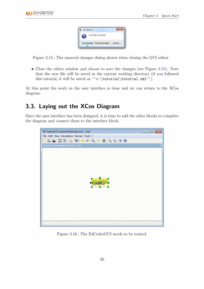
the Text property sets the title of the button. . . . . . . . . . . . . . . . 193.15. The unsaved changes dialog shown when closing the GUI editor. . . . . 203.16. The E4CoderGUI needs to be resized. . . . . . . . . . . . . . . . . . . . . 203.17. The E4CoderGUI block displays the GUI file name (‘‘tutorial.xml’’),
and the input and output ports’ names. . . . . . . . . . . . . . . . . . . 213.18. The properties for the Counter block. . . . . . . . . . . . . . . . . . . . . 223.19. Flipping a block. . . . . . . . . . . . . . . . . . . . . . . . . . . . . . . . 223.20. The properties for the DOLLAR m block. . . . . . . . . . . . . . . . . . . . 233.21. The settings of the second CONVERT block. . . . . . . . . . . . . . . . . . 243.22. The complete XCos diagram with all the connections in place. . . . . . . 243.24. The GUI window during simulation. . . . . . . . . . . . . . . . . . . . . . 253.23. The Setup option of the Simulate menu (a) allows to set many simulation
parameters (b). . . . . . . . . . . . . . . . . . . . . . . . . . . . . . . . . 26
5

List of Figures
4.1. An E4CoderGUI block with two inputs and two outputs. . . . . . . . . . . 274.2. E4CoderGUI block properties dialog box. . . . . . . . . . . . . . . . . . . 274.3. E4CoderGUI block parameters. . . . . . . . . . . . . . . . . . . . . . . . . 28
5.1. The E4CoderGUI editor window. . . . . . . . . . . . . . . . . . . . . . . 295.2. An empty UI with the frame selected for editing. . . . . . . . . . . . . . 305.3. Adding an element from the palette. . . . . . . . . . . . . . . . . . . . . 305.4. Adding new elements by selecting them from the Add button (a) or from
the Insert menu (b). . . . . . . . . . . . . . . . . . . . . . . . . . . . . . 315.5. You can use these buttons to align the items in E4CoderGUI . . . . . . . 325.6. An image path property. . . . . . . . . . . . . . . . . . . . . . . . . . . . 335.7. Importing an image from outside the resource folder, i.e. the location of
the user interface definition file (.xml). . . . . . . . . . . . . . . . . . . . 335.8. Input (a) and output (b) ports in the content panel. . . . . . . . . . . . . 345.9. Connecting an input port to an element. . . . . . . . . . . . . . . . . . . 355.10. The File menu. . . . . . . . . . . . . . . . . . . . . . . . . . . . . . . . . 355.11. The Edit menu. . . . . . . . . . . . . . . . . . . . . . . . . . . . . . . . . 365.12. About panel. . . . . . . . . . . . . . . . . . . . . . . . . . . . . . . . . . . 365.13. Button element. . . . . . . . . . . . . . . . . . . . . . . . . . . . . . . . . 375.14. Button Image element. . . . . . . . . . . . . . . . . . . . . . . . . . . . . 375.15. Button Knob element. . . . . . . . . . . . . . . . . . . . . . . . . . . . . 375.16. Button LED element. . . . . . . . . . . . . . . . . . . . . . . . . . . . . . 385.17. Color Bar element. . . . . . . . . . . . . . . . . . . . . . . . . . . . . . . 385.18. Image element. . . . . . . . . . . . . . . . . . . . . . . . . . . . . . . . . 395.19. Needle element. . . . . . . . . . . . . . . . . . . . . . . . . . . . . . . . . 395.20. Plot element. . . . . . . . . . . . . . . . . . . . . . . . . . . . . . . . . . 405.21. Plotter 2D element. . . . . . . . . . . . . . . . . . . . . . . . . . . . . . 415.22. Rectangle element. . . . . . . . . . . . . . . . . . . . . . . . . . . . . . . 415.23. Roller element. . . . . . . . . . . . . . . . . . . . . . . . . . . . . . . . . 415.24. Slider element. . . . . . . . . . . . . . . . . . . . . . . . . . . . . . . . . 425.25. SpinBox element. . . . . . . . . . . . . . . . . . . . . . . . . . . . . . . . 425.26. Switch element. . . . . . . . . . . . . . . . . . . . . . . . . . . . . . . . . 425.27. Text Label element. . . . . . . . . . . . . . . . . . . . . . . . . . . . . . 435.28. Tracker 2D element. . . . . . . . . . . . . . . . . . . . . . . . . . . . . . 43
6.1. The examples for E4CoderGUI are available through the Scilab Demon-strations menu options (a), which will show the examples list (b). . . . . 44
6.2. The E4CoderGUI block in the Dashboard XCos diagram. . . . . . . . . . 456.3. The user interface for the Dashboard example. . . . . . . . . . . . . . . . 466.4. Curve modeling the input function for the Throttle in the Dashboard
example. . . . . . . . . . . . . . . . . . . . . . . . . . . . . . . . . . . . . 466.5. The XCos diagram for the Plotting example. . . . . . . . . . . . . . . . . 476.6. The user interface shown in the Plotting example. . . . . . . . . . . . . . 476.7. The Integers example user interface. . . . . . . . . . . . . . . . . . . . . . 48
6

List of Figures
6.8. The Integers example XCos model. . . . . . . . . . . . . . . . . . . . . . 48
7

List of Tables
5.1. List of the kinds of ports available and their corresponding types in XCos. 35
8

About this document
This document describes E4CoderGUI, a rapid prototyping tool to create graphical userinterfaces and integrate them with a XCos model.
Function of the document
The function of this document is to provide a reference manual for the various function-alities offered by E4CoderGUI.
Document history
Version Date Author Company Change Description
1.3 21 Mar 2015 Paolo Gai Evidence Srl First version availablewith Scilab support.
Acronyms
Acronym MeaningE4Coder E4Coder is a factorized acronym meaning “Evidence Erika
Enterprise Embedded Coder”. Initially meant as a codegeneration tool supporting the ERIKA Enterprise RTOS, itis now a general purpose code generation toolset. In thatsense, it can be now also interpreted as “Evidence For
Coder”, as a set of tools for simulation and code generationof complex designs.
E4Coder GUI E4Coder GUI is the GUI editor for fast prototyping ofgraphical user interfaces.
GUI Graphical User Interface
9

1. Introduction
E4CoderGUI is a tool useful for designing and simulating graphical user interfaces. WithE4CoderGUI, you will be able to:
• Design interactive graphical panels composed by a number of widgets.
• Integrate the panels inside a XCos [1] Diagram, connecting the widget animationsto the inputs and to the outputs of a E4CoderGUI XCos block.
• Interact with panels during XCos simulations.
The following Chapters will describe the main functionalities of E4CoderGUI, as well asits integration with XCos.
1.1. Quick feature list
This is a quick feature list of E4CoderGUI version 1.0:
• Visual design of Graphical User Interfaces (GUIs), with undo support.
• XML file format.
• Configuration of multiple input and output data with different types.
• Visualization of the GUI in a window during simulation.
• Export of GUIs screenshots in PNG format.
1.2. Requirements
E4CoderGUI is distributed with E4Coder, and has the following requirements:
• Scilab 5.5.1 for Windows, 32 or 64 bits;
1.3. Licensing
E4CoderGUI is distributed with a commercial license together with the E4Coder tool-box. E4CoderGUI uses the Qt Libraries, which are dynamically linked to allow you tochange the library with new versions at your choice. Licensing information about theQt Libraries is available in Appendix A.
10

Chapter 1. Introduction
1.4. Installation
E4CoderGUI is installed as part of E4Coder. Please refer to the E4Coder manual forthe installation procedure[2].
1.5. Technical support
For control the order status and license renewals you can refer to the E4Coder web site:http://www.e4coder.com
Technical support for E4Coder is available directly from Evidence. Please, contact ususing the forum:http://www.e4coder.com/forum/
For sales, pricing and general information, please contact Evidence Srl directly at theaddress and phone numbers available at the following web page:http://www.evidence.eu.com/en/contact-us.html
11

2. Use Cases
2.1. Rapid Prototyping
E4CoderGUI can be used for rapid prototyping of graphical user interfaces. Whencreating a XCos diagram, the user can also design a user interface mimicking the finalphysical implementation and connect the model I/O to the interface. In particular,E4CoderGUI provides many graphical elements whose appearance can be modified withcustom image, so that they can resemble the intended concrete interface.
This feature allows to work on the functional model and test the results in a simulatedenvironment as close as possible to the final interface (see Figure 2.1).
Figure 2.1.: A user interface used for rapid prototyping.
2.2. Simulation
E4CoderGUI can also assist in the creation of the functional model, by providing aquick way to set up an user interface that allows the configuration and fine-tuning ofthe model.
In this scenario, graphical elements such as sliders and plots can be used during thesimulation to dynamically change the input parameters of the model and to visualizethe results immediately.
12

3. Quick Start
This chapter will describe a step by step tutorial to create a simple XCos diagram witha Graphical User Interface (GUI). The tutorial is intended to offer a quick look at thefunctionalities provided by E4CoderGUI and an introduction to how to use it. Moredetailed information will be found in the next chapters.
3.1. Creating a New Diagram
The first steps detail the creation in XCos of a new diagram with a GUI block:
• We start from the hypothesis that E4Coder is already installed on the machine.
• Launch Scilab; the E4Coder Toolbox will be loaded automatically (see Figure 3.1).
Figure 3.1.: The Scilab console at startup. E4Coder is automatically loaded.
13

Chapter 3. Quick Start
• Change to the directory where you want to save the new diagram, e.g. ‘‘C:\tutorial’’(see Figure 3.2).
Figure 3.2.: Commands to launch XCos with a new diagram.
• Launch XCos with the new diagram file ‘‘tutorial.cos’’ (see Figure 3.2).
Figure 3.3.: Message warning that the specified file does not exist and will be createdupon save.
• Answer Yes to the warning about creating a new diagram (see Figure 3.3).
14

Chapter 3. Quick Start
Figure 3.4.: The menu item to access the Palette Tree, containing all the blocks that canbe added to a diagram.
• Once the XCos diagram window is open, select the Palette browser option fromthe View menu (see Figure 3.4).
• Look for the E4CoderGUI block, under “E4Coder - GUI creator”.
Figure 3.5.: An item from the Palettes window can be dragged into the diagram to createa new block.
• Drag E4CoderGUI into the diagram window, as shown in Figure 3.5.
• Double-click on the new block to edit it.
15

Chapter 3. Quick Start
(a) (b)
Figure 3.6.: In order to set the name of the GUI file for a block, double-click on it, chooseProperties (a), and then type the file name (b).
• Choose the Properties button as in Figure 3.6 (a).
• Type the name of the new GUI file (e.g. ‘‘tutorial.xml’’), as in Figure 3.6 (b).Note that the file name and path are relative to the current working directory.
• The system will report that the file does not exist, as in Figure 3.7. Please selectYes, and the E4CoderGUI window will appear.
Figure 3.7.: The system will report that tutorial.xml does not exist.
3.2. Designing the User Interface
This section will describe the creation of the user interface linked to the E4CoderGUI
block which was added to the diagram in the previous section. The GUI will consist ofa simple window with a text label and a button. The text label will show the integervalue read from an input port on the block, while the button state will be forwarded toan output port.
16

Chapter 3. Quick Start
Figure 3.8.: The Name property of the Frame is used to set the title of the user interfacewindow.
• Type the Name of the frame as in Figure 3.8.
• Select the “Input Ports” section on the left panel.
(a) (b)
Figure 3.9.: (a) Adding an Integer input port and (b) setting its name.
• Click on the Add button on the toolbar and select Integer, as in Figure 3.9 (a).
• Type the Name of the input port as in Figure 3.9 (b).
• Select the “Output Ports” section on the left panel.
17

Chapter 3. Quick Start
(a) (b)
Figure 3.10.: (a) Adding a Boolean output port and (b) setting its name.
• Click on the Add button on the toolbar and select Boolean, as in Figure 3.10 (a).
• Type the Name of the output port as in Figure 3.10 (b).
(a) (b) (c)
Figure 3.11.: To add a Text Label element, select it from the Palette (a), drag it intothe frame (b), and drop it at the center (c).
• Add a Text Label element from the palette on the right (Figure 3.11 (a)).
• Drag it to the center of the frame and drop it (Figure 3.11 (b-c)).
Figure 3.12.: The InputPort property links the Text Label element to an input port.
18

Chapter 3. Quick Start
• Edit the Name property of the Text Label.
• Set the InputPort property to “input-port”, as in Figure 3.12.
(a) (b) (c)
Figure 3.13.: To add a Text Label element, select it from the palette (a), drag it intothe frame (b), and drop it at the center (c).
• Add a Button element from the palette on the right (Figure 3.13 (a)).
• Drag it to the center of the frame and drop it (Figure 3.13 (b-c)).
(a) (b)
Figure 3.14.: The OutputPort property links the Button element to an output port (a),the Text property sets the title of the button.
• Edit the Name property of the Button.
• Set the OutputPort property to “output-port”, as in Figure 3.14 (a).
• Set the Text property to “Hold”, as in Figure 3.14 (b).
19
Chapter 3. Quick Start
Figure 3.15.: The unsaved changes dialog shown when closing the GUI editor.
• Close the editor window and choose to save the changes (see Figure 3.15). Notethat the new file will be saved in the current working directory (if you followedthis tutorial, it will be saved as ‘‘c:\tutorial\tutorial.xml’’).
At this point the work on the user interface is done and we can return to the XCosdiagram.
3.3. Laying out the XCos Diagram
Once the user interface has been designed, it is time to add the other blocks to completethe diagram and connect them to the interface block.
Figure 3.16.: The E4CoderGUI needs to be resized.
20

Chapter 3. Quick Start
• Once saved, the E4CoderGUI block reports the input and output ports specifiedinside the previous section, as shown in Figure 3.16 (a). We suggest to first resizethe block by dragging the green angles.
Figure 3.17.: The E4CoderGUI block displays the GUI file name (‘‘tutorial.xml’’),and the input and output ports’ names.
• The E4CoderGUI block should now look as in Figure 3.17. Note how the inputand output ports’ names are now fully visible and correspond to those set in theeditor.
• From the Sources palette, add a CLOCK c block.
21

Chapter 3. Quick Start
Figure 3.18.: The properties for the Counter block.
• Again from the Sources palette, add a Counter block.
• Double-click on the Counter block, and set its properties as follows (Figure 3.18):
– set the Minimum to 0,
– set the Width to 100,
– set the Rule to 2 (Decrement).
Figure 3.19.: Flipping a block.
22

Chapter 3. Quick Start
• Add a IFTHEL f block from the Event Handling palette.
• Flip the IFTHEL f block by right-clicking on it and selecting “Mirror” from the“Format” popup menu, as in Figure 3.19.
Figure 3.20.: The properties for the DOLLAR m block.
• From the Linear palette, add a DOLLAR m block and mirror it too.
• Double-click on the DOLLAR m block and set its Inherit property to 1 (yes).
• Add two CONVERT block from the Integer palette.
• Make the following connections:
– The EventOut port of the CLOCK c block to the EventIn ports of the IFTHEL f,and E4CoderGUI blocks.
– The “else” EventOut port of the IFTHEL f block to the EventIn port of theCounter block.
– The Output port of the Counter block to the Input port of the first CONVERTblock.
– The Output port of the first CONVERT block to the “input-port” of the E4CoderGUIblock.
– The “output-port” of the E4CoderGUI block to the second CONVERT block.
– Input port of the DOLLAR m block.
– The Output port of the DOLLAR m block to the Input port of the IFTHEL f
block.
• Finally, change the second CONVERT block (the one attached to the output of theE4CoderGUI block) to the settings shown in Figure 3.21. This is needed to convertthe boolean output of the button in the E4CoderGUI panel to a real value forthe DOLLAR m block.
23

Chapter 3. Quick Start
Figure 3.21.: The settings of the second CONVERT block.
Figure 3.22.: The complete XCos diagram with all the connections in place.
The whole diagram should now look as in Figure 3.22.
3.4. Simulation
We are now almost ready to start simulating our model. But first we need to set-up afew simulation parameters:
• Select Setup from the Simulate menu, as in Figure 3.23 (a).
24

Chapter 3. Quick Start
• Set the following properties (Figure 3.23 (b)):
– Final integration time to 3001,
– Realtime scaling to 12.
Figure 3.24.: The GUI window during simulation.
In order to start the simulation, choose Run from the Simulate menu. A windowcontaining the user interface will appear, as in Figure 3.24. The Text Label elementwill display the value from the counter, decreasing over time from 100 to 0. The Holdbutton will allow the user to pause the counter when pressed.
1Which is automatically changed after insertion to 3.0E02.2Which is automatically changed after insertion to 1.0E00.
25

Chapter 3. Quick Start
(a)
(b)
Figure 3.23.: The Setup option of the Simulate menu (a) allows to set many simulationparameters (b).
26

4. Integration with XCos
E4CoderGUI provides a customized block which can be used to integrate one or moreuser interface windows inside a XCos diagram. The block, named E4CoderGUI (seeFigure 4.1), allows to design and then simulate a graphical user interface with a variablenumber of inputs and outputs.
Figure 4.1.: An E4CoderGUI block with two inputs and two outputs.
The number and types of inputs and outputs depends on the ports configured in theinterface editor. There can be more than one E4CoderGUI block inside a XCos diagram.
Double clicking on the E4CoderGUI block opens the Property Dialog Box as shown inFigure 4.2. The window shows two possible options:
Editor: which can be used to design the user interface (see Chapter [chap:editor]).
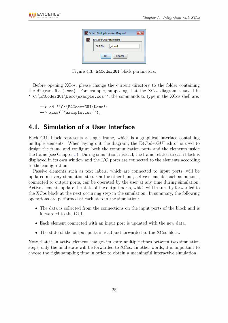
Properties: which can be used to specify the XML file that will contain the descriptionof the user interface associated with the block (See Figure 4.3).
Figure 4.2.: E4CoderGUI block properties dialog box.
The description of the user interface is stored in an external XML file (GUI file); youcan specify just the file name (e.g. ‘‘example.xml’’) or the file name with path infor-mation (e.g. ‘‘C:\E4CoderGUI\Demo\example.xml’’) . The same file can be specifiedfor more than one E4CoderGUI XCos blocks.
27
Chapter 4. Integration with XCos
Figure 4.3.: E4CoderGUI block parameters.
Before opening XCos, please change the current directory to the folder containingthe diagram file (.cos). For example, supposing that the XCos diagram is saved in‘‘C:\E4CoderGUI\Demo\example.cos’’, the commands to type in the XCos shell are:
--> cd ‘‘C:\E4CoderGUI\Demo’’--> xcos(‘‘example.cos’’);
4.1. Simulation of a User Interface
Each GUI block represents a single frame, which is a graphical interface containingmultiple elements. When laying out the diagram, the E4CoderGUI editor is used todesign the frame and configure both the communication ports and the elements insidethe frame (see Chapter 5). During simulation, instead, the frame related to each block isdisplayed in its own window and the I/O ports are connected to the elements accordingto the configuration.
Passive elements such as text labels, which are connected to input ports, will beupdated at every simulation step. On the other hand, active elements, such as buttons,connected to output ports, can be operated by the user at any time during simulation.Active elements update the state of the output ports, which will in turn by forwarded tothe XCos block at the next occurring step in the simulation. In summary, the followingoperations are performed at each step in the simulation:
• The data is collected from the connections on the input ports of the block and isforwarded to the GUI.
• Each element connected with an input port is updated with the new data.
• The state of the output ports is read and forwarded to the XCos block.
Note that if an active element changes its state multiple times between two simulationsteps, only the final state will be forwarded to XCos. In other words, it is important tochoose the right sampling time in order to obtain a meaningful interactive simulation.
28

5. The E4CoderGUI Editor
The E4CoderGUI editor is started after clicking on the Editor button in the E4CoderGUIblock properties dialog box. The E4CoderGUI editor appears as shown in Figure 5.1.
Figure 5.1.: The E4CoderGUI editor window.
The user interface is composed of the following graphical regions:
• A menu bar, with the usual commands for file handling, Cut & Paste, Export, andso on..
• The contents panel (on the left), showing a list of the elements already placed inthe user interface, together with the input and output ports.
• The elements palette (on the right), containing the elements that can be added tothe user interface.
• The working area (at the center), which is a representation of the user interfacepanel.
• The properties editor (at the bottom), which allows to set the properties of theselected element.
29

Chapter 5. The E4CoderGUI Editor
5.1. Frame and Elements
A user interface designed with E4CoderGUI is composed by a frame and several elementsinside it. In the simulation phase the frame will appear inside a window; in the designphase, it is represented graphically in the working area and can also be found at theroot of the contents tree on the left (see Figure 5.2).
Figure 5.2.: An empty UI with the frame selected for editing.
While the frame is selected, the user can modify it in two ways:
• By dragging the blue triangle in the lower left corner of the frame shown in theworking area, the user can resize the frame to the desired width and height.
• By editing its properties in the Properties Editor at the bottom of the window.
Figure 5.3.: Adding an element from the palette.
A frame contains other interface elements, such as buttons, images, text labels, andother widgets. These elements can be added to the frame in various ways:
30

Chapter 5. The E4CoderGUI Editor
Drag & Drop: the elements can be dragged from the palette on the right and droppedinto the frame in the working area, as shown in Figure 5.3.
Add button: the drop-down menu activated by the Add button above the content panelallows to insert a new element of the desired kind (see Figure 5.4(a)).
Insert menu: the Insert menu, shown in Figure 5.4(b), also allows to insert new ele-ments.
(a) (b)
Figure 5.4.: Adding new elements by selecting them from the Add button (a) or from theInsert menu (b).
Once an element is placed in the working area, it can be moved to a new position byclicking inside its bounding box and dragging it with the mouse. It can also be resizedby acting on the blue triangle in its lower left corner, similarly to how described for thewhole frame.
Additional operations that can be performed on an element are:
Deletion: an element can be removed by pressing the Delete key, clicking on the Removebutton in the content panel toolbar, or by selecting Remove from the Edit menu.
Reordering: the Up and Down arrows in the content panel toolbar (or the correspondingitems in the Edit menu) allows to change the order of the elements. This affectsthe order in which overlapping elements are drawn: elements appearing later inthe list will be drawn on top of previous elements.
31

Chapter 5. The E4CoderGUI Editor
Selection and alignment: a set of items can be selected using mouse clicks (while press-ing the Shift key), or by mouse selection on the Frame tab. Once selected, itemscan be aligned by using the buttons in the toolbar (see Figure 5.5).
Figure 5.5.: You can use these buttons to align the items in E4CoderGUI
5.2. Properties
The Properties panel shows a list of the properties of the currently selected object.The user can select any object in the content panel: the frame, its elements, and theinput/output ports. Moreover, an element can also be selected in the working area,where it will be highlighted with a blue rectangle. The frame itself can be selected byclicking on any point of the working area outside of an element bounding box.
The actual list of properties varies with each kind of object. However, the mostcommon properties include:
Name: Every object can be given a name, although it is only used to help the useridentify the object in the content panel or when connecting ports. The exceptionis the name of the whole frame, which is displayed in the window title bar duringsimulation.
Size: All graphical elements (frame included) have a size property which specifies theelement’s width and height in pixels.
Position: This property specifies the x, y coordinates (in pixels) of the elements relativeto the frame.
Input/Output Ports: These properties are used to connect an element to a communi-cation port (see Section 5.3).
Font: Many elements allow to select the font in which text will be displayed. The fontproperty shows the name, style, and size of the selected font and provides a dialogwhere the user can pick any font among those installed in the system. Please notethat when a user interface is opened on a different system, the previously selectedfonts may not be installed. In such cases the system default font will be usedinstead.
Color: An element can have multiple color properties (e.g. text color, background color,etc.). The color can be set by typing the RGBA hexadecimal string representingthe color, or by opening the color picker.
32

Chapter 5. The E4CoderGUI Editor
(a)
(b)
(c)
Figure 5.6.: An image path property.
Figure 5.7.: Importing an image from outside the resource folder, i.e. the location of theuser interface definition file (.xml).
Images: Elements that can visualize external images have one or more imagePath prop-erties to specify the path of the images. Allowed path must be relative either tothe resource folder, i.e. the location of the user interface definition file (.xml), orto the default images location. Figure 5.6 shows the buttons that allow to browsethe file-system to select the image from the resource folder (a), from the defaultimage library (b), or to reset the property (c). If the user chooses an image filethat is located outside the resource folder, an option is shown allowing to save acopy of the file inside it (see Figure 5.7).
The Frame object allows to set an additional fullScreen property to control the appear-ance of the frame during simulation. If this property is set to true, the frame windowwill be shown in full-screen during simulation. When in this mode, it is always possibleto close the window, and terminate the simulation, by pressing ALT-F4. Other system-wide keys combinations also work (e.g. ALT-TAB). The default value for the fullScreen
property is false.
5.3. Managing Ports
Ports enable data exchange from the XCos block to the user interface and vice-versa.The user can manage input and output ports in the content panel, as shown in Figure5.8. The basic operations on ports are:
• Adding a port: both the input and the output port lists allow to add a new port
33

Chapter 5. The E4CoderGUI Editor
(a) (b)
Figure 5.8.: Input (a) and output (b) ports in the content panel.
by clicking on the Add button or by selecting the Insert menu. Available ports arelisted in Table 5.1.
• Removing a port: input and output ports can be removed by clicking on the Removebutton, by selecting Delete Selection from the Edit menu, or by pressing theDelete key.
• Reordering ports: the Up and Down arrow buttons allow to change the order of theports. This affects the connections in the XCos diagram, as the order is replicatedin the order of the inputs/outputs of the block.
• Renaming a port: every port can be renamed by editing its Name property in theproperties panel.
Additionally, input ports of kind Text have a Length property that allows to set thedesired maximum text length accepted on that port.
Any changes to the ports will be reflected on the XCos block once the file is savedand the editor window is closed.
34

Chapter 5. The E4CoderGUI Editor
Kind XCos Type
Input Ports
Boolean int32Integer int32Real doubleText uint8[length]
Output PortsBoolean int32Integer int32Real double
Table 5.1.: List of the kinds of ports available and their corresponding types in XCos.
5.3.1. Connections
Figure 5.9.: Connecting an input port to an element.
All the elements have one or more properties of type either inputPort or outputPortwhich allow to connect the element to a port. Figure 5.9 shows an example of editingan inputPort property by selecting one of the existing input ports. Note that if theproperty is left empty, the element will be disconnected from any port.
During the simulation phase, an input port will send to any connected element thedata received from the XCos block. Depending on the specific element, the data willthen be displayed, or at least affect the state of the element. Conversely, output portswill receive data from the element which they are connected to and forward it to theXCos block.
5.4. Menus
Figure 5.10.: The File menu.
35
Chapter 5. The E4CoderGUI Editor
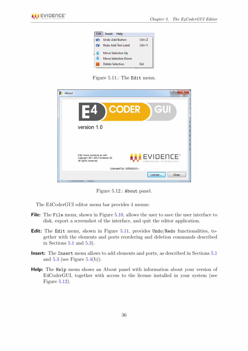
Figure 5.11.: The Edit menu.
Figure 5.12.: About panel.
The E4CoderGUI editor menu bar provides 4 menus:
File: The File menu, shown in Figure 5.10, allows the user to save the user interface todisk, export a screenshot of the interface, and quit the editor application.
Edit: The Edit menu, shown in Figure 5.11, provides Undo/Redo functionalities, to-gether with the elements and ports reordering and deletion commands describedin Sections 5.1 and 5.3).
Insert: The Insert menu allows to add elements and ports, as described in Sections 5.1and 5.3 (see Figure 5.4(b)).
Help: The Help menu shows an About panel with information about your version ofE4CoderGUI, together with access to the license installed in your system (seeFigure 5.12).
36

Chapter 5. The E4CoderGUI Editor
5.5. Interface Elements
This section contains a description of all the elements that can be added to an userinterface frame. For each element, a brief description is provided together with adviceon how to set it up properly. Important properties besides common ones such as Name,Size, and Position will also be discussed.
5.5.1. Button
Figure 5.13.: Button element.
The Button element, shown in Figure 5.13, represents a clickable widget with 2 states:Pressed and Released. The state of the button is sent to the output port connectedthrough the OutputPort property as a Boolean value, with 1 representing the Pressed
state and 0 the Released state. The user can also change the caption of the button bysetting the Text property.
5.5.2. Button Image
Figure 5.14.: Button Image element.
The Button Image element, shown in Figure 5.14, is quite similar to the Button ele-ment, with the main difference being that the user has to specify two images to representthe two states. The two properties PressedImagePath and ReleasedImagePath servethis purpose. As with the Button element, the state of the button is send to the outputport connected through the OutputPort. Note that a Button Image element has nocaption.
5.5.3. Button Knob
Figure 5.15.: Button Knob element.
The Button Knob element, shown in Figure 5.15, is a special kind of button thatcan be rotated by dragging with the mouse during the simulation. As with the Button
37

Chapter 5. The E4CoderGUI Editor
Image element, the user has to specify two images to represent the two states usingthe two properties PressedImagePath and ReleasedImagePath. However, besides theOutputPort property with the Pressed/Release state, a Button Knob also providesa RotationOutputPort which outputs the current rotation angle θ (in degrees) of theknob. Note that the knob rotates continuously, that is, multiple turns in one direction,e.g. counter-clockwise, will lead to values of θ ≥ 360.
5.5.4. Button LED
Figure 5.16.: Button LED element.
The Button LED element, shown in Figure 5.16, represents a button with an additionalActive/Inactive state. Together with the Pressed/Released state, this brings 4 statecombinations, which are all matched with a different image set with the 4 properties:ActivePressedImagePath, ActiveReleasedImagePath, InactivePressedImagePath,and InactiveReleasedImagePath. As with the other buttons, the Pressed/Releasestate is linked to the OutputPort property, while the Active/Inactive state is linkedto a Boolean input port, set through the InputPort property. Moreover, the initial stateof the button can be set with the IntialState property.
5.5.5. Color Bar
Figure 5.17.: Color Bar element.
The Color Bar element, shown in Figure 5.17, provides a graphical indicator for alevel or progress value, which is linked to an integer input port through the InputPort
property. In order to define the range of values, the user must set the Minimum andMaximum properties. Values outside the range will be clamped to the minimum or max-imum value. The Value property can be used to set the initial level of the bar.
The graphical appearance of the Color Bar can be customized by setting the followingproperties:
Orientation: Defines the orientation of the bar and takes the 4 values, TopToBottom,BottomToTop, LeftToRight, and RightToLeft.
38

Chapter 5. The E4CoderGUI Editor
FillColor: The color for the full portion of the bar.
BackgroundColor: The color for the background. Note that if the FillColor is notcompletely opaque, the BackgroundColor can be seen through it in the full portion.
TextOption: Selects the text mode:
• NoText: no text is shown;
• Absolute: the integer value is shown as a text label at the center of the bar;
• Percentage: the percentual value is calculated and shown at the center ofthe bar.
TextFont: Sets the font for the text label, if visible.
TextColor: Sets the color for the text label, if visible.
5.5.6. Image
Figure 5.18.: Image element.
The Image element, shown in Figure 5.18, draws an image according to its state, whichcan be Active/Inactive. The properties ActiveImagePath and InactiveImagePath
allow to set the image shown in each state. Note that if no image is set for one of thestates, the element will be effectively hidden when in that state. The Active/Inactivestate is linked to a boolean input port, set through the InputPort property. Moreover,the initial state of the element can be set with the IntialState property.
5.5.7. Needle
Figure 5.19.: Needle element.
The Needle element, shown in Figure 5.19, represents an indicator needle. The needlerotates following the input value provided by the real input port connected through the
39

Chapter 5. The E4CoderGUI Editor
InputPort property. The rotation assumes that the value is a counter-clockwise anglein degrees. An initial value for the angle can be set through the InitialValue property.
The image representing the needle is specified with the NeedleImagePath property.Additionally, a pivot point must be defined around which the rotation will take place.The ImagePivotPoint property sets the pivot on the image, while the ElementPivotPointsets the same point in the element coordinates.
5.5.8. Plot
Figure 5.20.: Plot element.
The Plot element, shown in Figure 5.20, provides basic plotting capabilities. Thiselement plots a data series showing the simulation steps on the X axis and the valueobtained from a real input port (connected through the InputPort property) on the Yaxis.
If the parameter yScaleType is set to Manual, then the scale is fixed to the range[yMinimum ... yMaximum]. If the parameter yScaleType is set to Automatic, then thescale on both axes will adjust dynamically with the range of input values as the simula-tion progresses. A special plotting mode can be obtained by setting a value higher than0 for the ScrollWindow property: the value will then be used to set a fixed-sized scaleon the X axis, which will scroll to the left as new input values are plotted. The color tobe used to plot the data series can be set through the LineColor property.
Note that a plot widget is never repainted with a frequency higher than 25Hz to avoidunwanted overhead on the graphical display routines.
5.5.9. Plotter 2D
The Plotter 2D element, shown in Figure 5.21, draws a marker image on a plane takingas input two coordinates. The properties XInputPort and YInputPort are used to setthe connection with two integer input ports, from which the values for the (x, y) coordi-nates will be read. The element will draw the image set through the MarkerImagePath
property centered at the point (x, y). The couple of properties InitialX and InitialY
can be used to set the initial location of the marker image. Finally, the BackgroundColorproperty sets the color of the element background.
40

Chapter 5. The E4CoderGUI Editor
Figure 5.21.: Plotter 2D element.
5.5.10. Rectangle
Figure 5.22.: Rectangle element.
The Rectangle element, shown in Figure 5.22, draws a rectangular area of a differ-ent color according to its Active/Inactive state. The properties ActiveColor andInactiveColor allow to set the color for each state. The Active/Inactive state islinked to a boolean input port, set through the InputPort property. Moreover, theinitial state of the element can be set with the IntialState property.
5.5.11. Roller and Slider
Figure 5.23.: Roller element.
The Roller element (Figure 5.23) and the Slider element (Figure 5.24) both allow toset an integer value inside a fixed range. The two elements are functionally equivalent and
41
Chapter 5. The E4CoderGUI Editor
Figure 5.24.: Slider element.
differ only in their appearance. The range of accepted values is set through the Minimum
and Maximum properties, while the initial position depends on the Value property. TheOutputPort property allows to forward the value to an integer output port. Finally, theVertical property switch the appearance of the element between vertical (true - thedefault for a Roller) and horizontal (false - the default for a Slider).
5.5.12. SpinBox
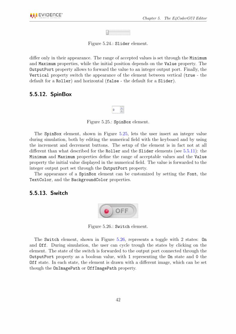
Figure 5.25.: SpinBox element.
The SpinBox element, shown in Figure 5.25, lets the user insert an integer valueduring simulation, both by editing the numerical field with the keyboard and by usingthe increment and decrement buttons. The setup of the element is in fact not at alldifferent than what described for the Roller and the Slider elements (see 5.5.11): theMinimum and Maximum properties define the range of acceptable values and the Value
property the initial value displayed in the numerical field. The value is forwarded to theinteger output port set through the OutputPort property.
The appearance of a SpinBox element can be customized by setting the Font, theTextColor, and the BackgroundColor properties.
5.5.13. Switch
Figure 5.26.: Switch element.
The Switch element, shown in Figure 5.26, represents a toggle with 2 states: On
and Off. During simulation, the user can cycle trough the states by clicking on theelement. The state of the switch is forwarded to the output port connected through theOutputPort property as a boolean value, with 1 representing the On state and 0 theOff state. In each state, the element is drawn with a different image, which can be setthough the OnImagePath or OffImagePath property.
42

Chapter 5. The E4CoderGUI Editor
Figure 5.27.: Text Label element.
5.5.14. Text Label
The Text Label element, shown in Figure 5.27, displays a text string on the screen.Through its InputPort property, it can be connected to any kind of input port (Text,Boolean, Integer, and Real): if needed, the input will be converted to a string beforebeing shown. The InitialText property allows to set an initial text string. The ap-pearance of a Text Label element can be further customized by setting the Font, theTextColor, and the BackgroundColor properties.
5.5.15. Tracker 2D
Figure 5.28.: Tracker 2D element.
The Tracker 2D element, shown in Figure 5.28, is functionally the opposite of thePlotter 2D element described in 5.5.9: like the Plotter 2D, it draws a marker imageon a plane, but during simulation it allows the user to click on its surface to set themarker coordinates. Moreover, the (x,y) coordinates set by the user are forwarded tothe integer output ports set through the properties XOutputPort and YOutputPort.
The appearance of a Tracker 2D element is identical to that of a Plotter 2D: theelement will draw the image set through the MarkerImagePath property centered at thepoint (x, y), whose initial location can be set through the couple of properties InitialXand InitialY. Finally, the BackgroundColor property sets the color of the elementbackground.
43

6. Examples
This Chapter shortly describes a few simple examples that can be used to demonstratethe features of E4CoderGUI. All the examples are listed in the E4Coder demos windowshown in Figure 6.1 (b), accessible through the Scilab Demonstration option of the ?
menu in the XCos window, as in Figure 6.1 (a).
(a)
(b)
Figure 6.1.: The examples for E4CoderGUI are available through the Scilab Demonstra-tions menu options (a), which will show the examples list (b).
6.1. Dashboard
The Dashboard example simulates an automotive drivetrain in order to model an au-tomatic transmission controller. The transmission controller is implemented in a XCos
44
Chapter 6. Examples
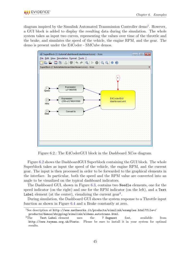
diagram inspired by the Simulink Automated Transmission Controller demo1. However,a GUI block is added to display the resulting data during the simulation. The wholesystem takes as input two curves, representing the values over time of the throttle andthe brake, and simulates the speed of the vehicle, the engine RPM, and the gear. Thedemo is present under the E4Coder - SMCube demos.
Figure 6.2.: The E4CoderGUI block in the Dashboard XCos diagram.
Figure 6.2 shows the DashboardGUI Superblock containing the GUI block. The wholeSuperblock takes as input the speed of the vehicle, the engine RPM, and the currentgear. The input is then processed in order to be forwarded to the graphical elements inthe interface. In particular, both the speed and the RPM value are converted into anangle to be visualized on the typical dashboard indicators.
The Dashboard GUI, shown in Figure 6.3, contains two Needle elements, one for thespeed indicator (on the right) and one for the RPM indicator (on the left), and a Text
Label element (at the center), visualizing the current gear2.During simulation, the Dashboard GUI shows the system response to a Throttle input
function as shown in Figure 6.4 and a Brake constantly at zero.
1See description at http://www.mathworks.it/products/simulink/examples.html?file=/products/demos/shipping/simulink/sldemo autotrans.html.
2The Text Label element uses the 7 Segment font, available fromhttp://www.twyman.org.uk/Fonts. Please be sure to install it in your system for optimalresults.
45

Chapter 6. Examples
Figure 6.3.: The user interface for the Dashboard example.
Figure 6.4.: Curve modeling the input function for the Throttle in the Dashboardexample.
6.2. Plotting
The Plotting example shows a graphical interface to display a sinusoid on a plot and aroller element to set the curve amplitude. Figure 6.5 shows the example diagram: theE4CoderGUI block, in yellow, takes the sinusoid data as input and the value for theamplitude as output.
The GUI shown during simulation (see Figure 6.6) is composed by a Plot elementthat displays the sinusoid in red, and a Roller element in the upper right corner thatallows the user to change dynamically the amplitude of the sinusoid. In the upper leftcorner, the current value of the input data plotted on the graph is also updated at everysimulation step.
46

Chapter 6. Examples
Figure 6.5.: The XCos diagram for the Plotting example.
Figure 6.6.: The user interface shown in the Plotting example.47

Chapter 6. Examples
6.3. Integers
The Integers example shows a collection of elements that allows the user to insert integervalues. The example user interface contains a Spinbox, a Roller, and two Sliders (withhorizontal and vertical orientation). The GUI during simulation is shown in Figure 6.7.
Figure 6.7.: The Integers example user interface.
Figure 6.8.: The Integers example XCos model.
Figure 6.8 shows the XCos model used in the example. Each integer output from theGUI block is converted to a double and then linked to a CSCOPE block in order to showthe resulting value.
48

A. QT Libraries Licensing
E4CoderGUI is written using the Qt Libraries, which are dynamically linked to theexecutable. The Qt GUI Toolkit is Copyright (C) 2011 Nokia Corporation and/or itssubsidiary(-ies), and the following license applies.
The GNU Lesser General Public License (Version 2.1)
GNU LESSER GENERAL PUBLIC LICENSEVersion 2.1, February 1999
Copyright (C) 1991, 1999 Free Software Foundation, Inc.51 Franklin Street, Fifth Floor, Boston, MA 02110-1301 USAEveryone is permitted to copy and distribute verbatim copies of this license document, but
changing it is not allowed.
[This is the first released version of the Lesser GPL. It also counts as the successor of theGNU Library Public License, version 2, hence the version number 2.1.]
Preamble
The licenses for most software are designed to take away your freedom to share and changeit. By contrast, the GNU General Public Licenses are intended to guarantee your freedom toshare and change free software–to make sure the software is free for all its users.
This license, the Lesser General Public License, applies to some specially designated softwarepackages–typically libraries–of the Free Software Foundation and other authors who decide touse it. You can use it too, but we suggest you first think carefully about whether this licenseor the ordinary General Public License is the better strategy to use in any particular case,based on the explanations below.
When we speak of free software, we are referring to freedom of use, not price. Our GeneralPublic Licenses are designed to make sure that you have the freedom to distribute copies offree software (and charge for this service if you wish); that you receive source code or can getit if you want it; that you can change the software and use pieces of it in new free programs;and that you are informed that you can do these things.
To protect your rights, we need to make restrictions that forbid distributors to deny youthese rights or to ask you to surrender these rights. These restrictions translate to certainresponsibilities for you if you distribute copies of the library or if you modify it.
For example, if you distribute copies of the library, whether gratis or for a fee, you mustgive the recipients all the rights that we gave you. You must make sure that they, too, receive
49

Appendix A. QT Libraries Licensing
or can get the source code. If you link other code with the library, you must provide completeobject files to the recipients, so that they can relink them with the library after making changesto the library and recompiling it. And you must show them these terms so they know theirrights.
We protect your rights with a two-step method: (1) we copyright the library, and (2) weoffer you this license, which gives you legal permission to copy, distribute and/or modify thelibrary.
To protect each distributor, we want to make it very clear that there is no warranty for thefree library. Also, if the library is modified by someone else and passed on, the recipients shouldknow that what they have is not the original version, so that the original author’s reputationwill not be affected by problems that might be introduced by others.
Finally, software patents pose a constant threat to the existence of any free program. Wewish to make sure that a company cannot effectively restrict the users of a free program byobtaining a restrictive license from a patent holder. Therefore, we insist that any patent licenseobtained for a version of the library must be consistent with the full freedom of use specifiedin this license.
Most GNU software, including some libraries, is covered by the ordinary GNU General PublicLicense. This license, the GNU Lesser General Public License, applies to certain designatedlibraries, and is quite different from the ordinary General Public License. We use this licensefor certain libraries in order to permit linking those libraries into non-free programs.
When a program is linked with a library, whether statically or using a shared library, thecombination of the two is legally speaking a combined work, a derivative of the original library.The ordinary General Public License therefore permits such linking only if the entire combi-nation fits its criteria of freedom. The Lesser General Public License permits more lax criteriafor linking other code with the library.
We call this license the “Lesser” General Public License because it does Less to protect theuser’s freedom than the ordinary General Public License. It also provides other free softwaredevelopers Less of an advantage over competing non-free programs. These disadvantages arethe reason we use the ordinary General Public License for many libraries. However, the Lesserlicense provides advantages in certain special circumstances.
For example, on rare occasions, there may be a special need to encourage the widest possibleuse of a certain library, so that it becomes a de-facto standard. To achieve this, non-freeprograms must be allowed to use the library. A more frequent case is that a free library doesthe same job as widely used non-free libraries. In this case, there is little to gain by limitingthe free library to free software only, so we use the Lesser General Public License.
In other cases, permission to use a particular library in non-free programs enables a greaternumber of people to use a large body of free software. For example, permission to use the GNUC Library in non-free programs enables many more people to use the whole GNU operatingsystem, as well as its variant, the GNU/Linux operating system.
50

Appendix A. QT Libraries Licensing
Although the Lesser General Public License is Less protective of the users’ freedom, it doesensure that the user of a program that is linked with the Library has the freedom and thewherewithal to run that program using a modified version of the Library.
The precise terms and conditions for copying, distribution and modification follow. Payclose attention to the difference between a “work based on the library” and a “work that usesthe library”. The former contains code derived from the library, whereas the latter must becombined with the library in order to run.
GNU LESSER GENERAL PUBLIC LICENSETERMS AND CONDITIONS FOR COPYING, DISTRIBUTION AND MODIFICATION
0. This License Agreement applies to any software library or other program which containsa notice placed by the copyright holder or other authorized party saying it may be distributedunder the terms of this Lesser General Public License (also called “this License”). Each licenseeis addressed as “you”.
A “library” means a collection of software functions and/or data prepared so as to beconveniently linked with application programs (which use some of those functions and data)to form executables.
The “Library”, below, refers to any such software library or work which has been distributedunder these terms. A “work based on the Library” means either the Library or any derivativework under copyright law: that is to say, a work containing the Library or a portion of it, eitherverbatim or with modifications and/or translated straightforwardly into another language.(Hereinafter, translation is included without limitation in the term “modification”.)
“Source code” for a work means the preferred form of the work for making modifications toit. For a library, complete source code means all the source code for all modules it contains,plus any associated interface definition files, plus the scripts used to control compilation andinstallation of the library.
Activities other than copying, distribution and modification are not covered by this License;they are outside its scope. The act of running a program using the Library is not restricted,and output from such a program is covered only if its contents constitute a work based on theLibrary (independent of the use of the Library in a tool for writing it). Whether that is truedepends on what the Library does and what the program that uses the Library does.
1. You may copy and distribute verbatim copies of the Library’s complete source code as youreceive it, in any medium, provided that you conspicuously and appropriately publish on eachcopy an appropriate copyright notice and disclaimer of warranty; keep intact all the noticesthat refer to this License and to the absence of any warranty; and distribute a copy of thisLicense along with the Library.
You may charge a fee for the physical act of transferring a copy, and you may at your optionoffer warranty protection in exchange for a fee.
51

Appendix A. QT Libraries Licensing
2. You may modify your copy or copies of the Library or any portion of it, thus forminga work based on the Library, and copy and distribute such modifications or work under theterms of Section 1 above, provided that you also meet all of these conditions:
a) The modified work must itself be a software library.
b) You must cause the files modified to carry prominent notices stating that you changedthe files and the date of any change.
c) You must cause the whole of the work to be licensed at no charge to all third partiesunder the terms of this License.
d) If a facility in the modified Library refers to a function or a table of data to be suppliedby an application program that uses the facility, other than as an argument passed when thefacility is invoked, then you must make a good faith effort to ensure that, in the event anapplication does not supply such function or table, the facility still operates, and performswhatever part of its purpose remains meaningful.
(For example, a function in a library to compute square roots has a purpose that is en-tirely well-defined independent of the application. Therefore, Subsection 2d requires that anyapplication-supplied function or table used by this function must be optional: if the applicationdoes not supply it, the square root function must still compute square roots.)
These requirements apply to the modified work as a whole. If identifiable sections of thatwork are not derived from the Library, and can be reasonably considered independent andseparate works in themselves, then this License, and its terms, do not apply to those sectionswhen you distribute them as separate works. But when you distribute the same sections aspart of a whole which is a work based on the Library, the distribution of the whole must beon the terms of this License, whose permissions for other licensees extend to the entire whole,and thus to each and every part regardless of who wrote it.
Thus, it is not the intent of this section to claim rights or contest your rights to work writtenentirely by you; rather, the intent is to exercise the right to control the distribution of derivativeor collective works based on the Library.
In addition, mere aggregation of another work not based on the Library with the Library(or with a work based on the Library) on a volume of a storage or distribution medium doesnot bring the other work under the scope of this License.
3. You may opt to apply the terms of the ordinary GNU General Public License insteadof this License to a given copy of the Library. To do this, you must alter all the notices thatrefer to this License, so that they refer to the ordinary GNU General Public License, version2, instead of to this License. (If a newer version than version 2 of the ordinary GNU GeneralPublic License has appeared, then you can specify that version instead if you wish.) Do notmake any other change in these notices.
Once this change is made in a given copy, it is irreversible for that copy, so the ordinaryGNU General Public License applies to all subsequent copies and derivative works made fromthat copy.
This option is useful when you wish to copy part of the code of the Library into a programthat is not a library.
52

Appendix A. QT Libraries Licensing
4. You may copy and distribute the Library (or a portion or derivative of it, under Section2) in object code or executable form under the terms of Sections 1 and 2 above provided thatyou accompany it with the complete corresponding machine-readable source code, which mustbe distributed under the terms of Sections 1 and 2 above on a medium customarily used forsoftware interchange.
If distribution of object code is made by offering access to copy from a designated place, thenoffering equivalent access to copy the source code from the same place satisfies the requirementto distribute the source code, even though third parties are not compelled to copy the sourcealong with the object code.
5. A program that contains no derivative of any portion of the Library, but is designed towork with the Library by being compiled or linked with it, is called a “work that uses theLibrary”. Such a work, in isolation, is not a derivative work of the Library, and therefore fallsoutside the scope of this License.
However, linking a “work that uses the Library” with the Library creates an executable thatis a derivative of the Library (because it contains portions of the Library), rather than a “workthat uses the library”. The executable is therefore covered by this License. Section 6 statesterms for distribution of such executables.
When a “work that uses the Library” uses material from a header file that is part of theLibrary, the object code for the work may be a derivative work of the Library even thoughthe source code is not. Whether this is true is especially significant if the work can be linkedwithout the Library, or if the work is itself a library. The threshold for this to be true is notprecisely defined by law.
If such an object file uses only numerical parameters, data structure layouts and accessors,and small macros and small inline functions (ten lines or less in length), then the use of theobject file is unrestricted, regardless of whether it is legally a derivative work. (Executablescontaining this object code plus portions of the Library will still fall under Section 6.)
Otherwise, if the work is a derivative of the Library, you may distribute the object code forthe work under the terms of Section 6. Any executables containing that work also fall underSection 6, whether or not they are linked directly with the Library itself.
6. As an exception to the Sections above, you may also combine or link a “work that uses theLibrary” with the Library to produce a work containing portions of the Library, and distributethat work under terms of your choice, provided that the terms permit modification of the workfor the customer’s own use and reverse engineering for debugging such modifications.
You must give prominent notice with each copy of the work that the Library is used init and that the Library and its use are covered by this License. You must supply a copy ofthis License. If the work during execution displays copyright notices, you must include thecopyright notice for the Library among them, as well as a reference directing the user to thecopy of this License. Also, you must do one of these things:
a) Accompany the work with the complete corresponding machine-readable source code forthe Library including whatever changes were used in the work (which must be distributed under
53

Appendix A. QT Libraries Licensing
Sections 1 and 2 above); and, if the work is an executable linked with the Library, with thecomplete machine-readable “work that uses the Library”, as object code and/or source code,so that the user can modify the Library and then relink to produce a modified executablecontaining the modified Library. (It is understood that the user who changes the contents ofdefinitions files in the Library will not necessarily be able to recompile the application to usethe modified definitions.)
b) Use a suitable shared library mechanism for linking with the library. A suitable mech-anism is one that (1) uses at run time a copy of the library already present on the user’scomputer system, rather than copying library functions into the executable, and (2) will op-erate properly with a modified version of the library, if the user installs one, as long as themodified version is interface-compatible with the version that the work was made with.
c) Accompany the work with a written offer, valid for at least three years, to give the sameuser the materials specified in Subsection 6a, above, for a charge no more than the cost ofperforming this distribution.
d) If distribution of the work is made by offering access to copy from a designated place,offer equivalent access to copy the above specified materials from the same place.
e) Verify that the user has already received a copy of these materials or that you have alreadysent this user a copy.
For an executable, the required form of the “work that uses the Library” must includeany data and utility programs needed for reproducing the executable from it. However, as aspecial exception, the materials to be distributed need not include anything that is normallydistributed (in either source or binary form) with the major components (compiler, kernel,and so on) of the operating system on which the executable runs, unless that component itselfaccompanies the executable.
It may happen that this requirement contradicts the license restrictions of other proprietarylibraries that do not normally accompany the operating system. Such a contradiction meansyou cannot use both them and the Library together in an executable that you distribute.
7. You may place library facilities that are a work based on the Library side-by-side in asingle library together with other library facilities not covered by this License, and distributesuch a combined library, provided that the separate distribution of the work based on theLibrary and of the other library facilities is otherwise permitted, and provided that you dothese two things:
a) Accompany the combined library with a copy of the same work based on the Library,uncombined with any other library facilities. This must be distributed under the terms of theSections above.
b) Give prominent notice with the combined library of the fact that part of it is a workbased on the Library, and explaining where to find the accompanying uncombined form of thesame work.
8. You may not copy, modify, sublicense, link with, or distribute the Library except asexpressly provided under this License. Any attempt otherwise to copy, modify, sublicense, linkwith, or distribute the Library is void, and will automatically terminate your rights under this
54

Appendix A. QT Libraries Licensing
License. However, parties who have received copies, or rights, from you under this License willnot have their licenses terminated so long as such parties remain in full compliance.
9. You are not required to accept this License, since you have not signed it. However,nothing else grants you permission to modify or distribute the Library or its derivative works.These actions are prohibited by law if you do not accept this License. Therefore, by modifyingor distributing the Library (or any work based on the Library), you indicate your acceptanceof this License to do so, and all its terms and conditions for copying, distributing or modifyingthe Library or works based on it.
10. Each time you redistribute the Library (or any work based on the Library), the recipientautomatically receives a license from the original licensor to copy, distribute, link with or modifythe Library subject to these terms and conditions. You may not impose any further restrictionson the recipients’ exercise of the rights granted herein. You are not responsible for enforcingcompliance by third parties with this License.
11. If, as a consequence of a court judgment or allegation of patent infringement or forany other reason (not limited to patent issues), conditions are imposed on you (whether bycourt order, agreement or otherwise) that contradict the conditions of this License, they donot excuse you from the conditions of this License. If you cannot distribute so as to satisfysimultaneously your obligations under this License and any other pertinent obligations, then asa consequence you may not distribute the Library at all. For example, if a patent license wouldnot permit royalty-free redistribution of the Library by all those who receive copies directly orindirectly through you, then the only way you could satisfy both it and this License would beto refrain entirely from distribution of the Library.
If any portion of this section is held invalid or unenforceable under any particular circum-stance, the balance of the section is intended to apply, and the section as a whole is intendedto apply in other circumstances.
It is not the purpose of this section to induce you to infringe any patents or other propertyright claims or to contest validity of any such claims; this section has the sole purpose ofprotecting the integrity of the free software distribution system which is implemented by publiclicense practices. Many people have made generous contributions to the wide range of softwaredistributed through that system in reliance on consistent application of that system; it is upto the author/donor to decide if he or she is willing to distribute software through any othersystem and a licensee cannot impose that choice.
This section is intended to make thoroughly clear what is believed to be a consequence ofthe rest of this License.
12. If the distribution and/or use of the Library is restricted in certain countries eitherby patents or by copyrighted interfaces, the original copyright holder who places the Libraryunder this License may add an explicit geographical distribution limitation excluding thosecountries, so that distribution is permitted only in or among countries not thus excluded. Insuch case, this License incorporates the limitation as if written in the body of this License.
55

Appendix A. QT Libraries Licensing
13. The Free Software Foundation may publish revised and/or new versions of the LesserGeneral Public License from time to time. Such new versions will be similar in spirit to thepresent version, but may differ in detail to address new problems or concerns.
Each version is given a distinguishing version number. If the Library specifies a versionnumber of this License which applies to it and “any later version”, you have the option offollowing the terms and conditions either of that version or of any later version published bythe Free Software Foundation. If the Library does not specify a license version number, youmay choose any version ever published by the Free Software Foundation.
14. If you wish to incorporate parts of the Library into other free programs whose distri-bution conditions are incompatible with these, write to the author to ask for permission. Forsoftware which is copyrighted by the Free Software Foundation, write to the Free SoftwareFoundation; we sometimes make exceptions for this. Our decision will be guided by the twogoals of preserving the free status of all derivatives of our free software and of promoting thesharing and reuse of software generally.
NO WARRANTY
15. BECAUSE THE LIBRARY IS LICENSED FREE OF CHARGE, THERE IS NOWARRANTY FOR THE LIBRARY, TO THE EXTENT PERMITTED BY APPLICABLELAW. EXCEPT WHEN OTHERWISE STATED IN WRITING THE COPYRIGHT HOLD-ERS AND/OR OTHER PARTIES PROVIDE THE LIBRARY “AS IS” WITHOUT WAR-RANTY OF ANY KIND, EITHER EXPRESSED OR IMPLIED, INCLUDING, BUT NOTLIMITED TO, THE IMPLIED WARRANTIES OF MERCHANTABILITY AND FITNESSFOR A PARTICULAR PURPOSE. THE ENTIRE RISK AS TO THE QUALITY AND PER-FORMANCE OF THE LIBRARY IS WITH YOU. SHOULD THE LIBRARY PROVE DE-FECTIVE, YOU ASSUME THE COST OF ALL NECESSARY SERVICING, REPAIR ORCORRECTION.
16. IN NO EVENT UNLESS REQUIRED BY APPLICABLE LAW OR AGREED TOIN WRITING WILL ANY COPYRIGHT HOLDER, OR ANY OTHER PARTY WHO MAYMODIFY AND/OR REDISTRIBUTE THE LIBRARY AS PERMITTED ABOVE, BE LI-ABLE TO YOU FOR DAMAGES, INCLUDING ANY GENERAL, SPECIAL, INCIDENTALOR CONSEQUENTIAL DAMAGES ARISING OUT OF THE USE OR INABILITY TO USETHE LIBRARY (INCLUDING BUT NOT LIMITED TO LOSS OF DATA OR DATA BEINGRENDERED INACCURATE OR LOSSES SUSTAINED BY YOU OR THIRD PARTIES ORA FAILURE OF THE LIBRARY TO OPERATE WITH ANY OTHER SOFTWARE), EVENIF SUCH HOLDER OR OTHER PARTY HAS BEEN ADVISED OF THE POSSIBILITY OFSUCH DAMAGES.
END OF TERMS AND CONDITIONS
How to Apply These Terms to Your New Libraries
If you develop a new library, and you want it to be of the greatest possible use to the public,we recommend making it free software that everyone can redistribute and change. You can
56

Appendix A. QT Libraries Licensing
do so by permitting redistribution under these terms (or, alternatively, under the terms of theordinary General Public License).
To apply these terms, attach the following notices to the library. It is safest to attach themto the start of each source file to most effectively convey the exclusion of warranty; and eachfile should have at least the “copyright” line and a pointer to where the full notice is found.
¡one line to give the library’s name and a brief idea of what it does.¿Copyright (C) ¡year¿ ¡name of author¿
This library is free software; you can redistribute it and/or modify it under the terms ofthe GNU Lesser General Public License as published by the Free Software Foundation; eitherversion 2.1 of the License, or (at your option) any later version.
This library is distributed in the hope that it will be useful, but WITHOUT ANY WAR-RANTY; without even the implied warranty of MERCHANTABILITY or FITNESS FOR APARTICULAR PURPOSE. See the GNU Lesser General Public License for more details. Youshould have received a copy of the GNU Lesser General Public License along with this library;if not, write to the Free Software Foundation, Inc., 51 Franklin Street, Fifth Floor, Boston,MA 02110-1301 USA
Also add information on how to contact you by electronic and paper mail.
You should also get your employer (if you work as a programmer) or your school, if any, tosign a “copyright disclaimer” for the library, if necessary. Here is a sample; alter the names:
Yoyodyne, Inc., hereby disclaims all copyright interest in the library ‘Frob’ (a library fortweaking knobs) written by James Random Hacker.
¡signature of Ty Coon¿, 1 April 1990Ty Coon, President of Vice
That’s all there is to it!
57

Bibliography
[1] Scilab Enterprises. Scilab. http://www.scilab.org/.
[2] Evidence Srl. E4coder reference manual, code generation tools for embedded designs.
58