e technical notes - nasa · e technical notes -.- national advisory cokl!ittze for aeronawtics ....
TRANSCRIPT

e TECHNICAL NOTES -.- ----
NATIONAL ADVISORY COKl!ITTZE FOR AERONAWTICS .
No, 636
_. =--
TEE ESTIMATIOX OF THjj! RATZ OF CRANGE OF YATPIEG
XOMEBT 'iVITH SIDESEIP . , __. :: I _
By Zreaerick H. Inlay Langley Memorial Aeronautical LaboratoSy
Trrsshin,-t cn Fcbrua?y 1938
https://ntrs.nasa.gov/search.jsp?R=19930081480 2018-06-03T19:45:17+00:00Z

NATIONAL ADVISORY'C:MMI%TEE FOR AERONAUTICS --I-
TECHNICAL NOTE NO. 636 --
THE ESTIMATION OF THE RATE OF CHANGE OF YAi7ING
MOhlENT SMITH SIDESLIP
By Frederick H. Imlay
SUMMARY .XL ..-..-. _..
mind-tunnel data are presented on the rate of change of yawing moment with sideslip for tests of 9 complete airplane models, 20 fuselage shapes, and 3 nfng models rrith various combinations of dihedral, srreepback, and tnist. The data wore collected during a survey of exist- ing information, which was made to find a reliable rnethod , of computing the yawping moment due to sidoslip. Impor- tant errors common to methods of computation used at D-ros- ent appear to be due to large interference effects, the investigation of which rrill undoubtedly.require an exten- sive program of systematic aind-tunnel tests. At present it is necessary to place considerable reliance on past - _L design experience in proportioning an airplane so as to obtain a reasonable degree of directional stdbility. L- .-
.-
INTRODUCTION .-
Theoretical studies of later.4 stability (reference 1) have sho-sn that the rate of chnnge of yawing-moment coefficient with angle of sideslip dCn/d@ 9 is one of the more important factors influencing the lateral-stabfltty characteristics of an airplane. At present there exists no depondsble method of computing this factor-from the di- mensions of an airplane. Several methods of estimating its agproximate value are in use but they have proved to be inaccurate rrhen the results are compare-d with those fron mind-tunnel tests. In an attempt to devise arelia- blo method of determining the value of the derrvative for -. an nirplano in tho course of dosign, a study has bcon made of all avaflable wind-tunnel data on the subject.
During tho survey, the rosults of aind-tunnel tests of 127 airplane models mere analyzed. The models embraced

2 N;A.C.A. Technical Note No. 636 .
a wide variety of designs, including such diverse types as racing seaplanes and troop and cargo carriers. In 1 spite of the large number of test results available, no satisfactory method of estimating dcn/dP was developed .3 because. the data offered little apportunity for the study of interference effects. Indications.are that the inter- ference effects between comFonents of-the airplane may change the yarning moment for the.combination by an amount equal to the sum of the yarning moments obtained when the components are tested separately.. An extonsivo program of correlated mind-tunnel tests mill probably be required to pormit the isolation and c?.nalysis of these interfor- -- ence effects.
In thb absence of an accurate method of estimation, certain of the more useful data collected during the study are presented as an aid to the designer in judging the value of dc,/dP 'for complete ai'rplanes or component parts. . . .
PRESENTATION OF DATA
As theoretical considerations indicate that the value of dCn/ d B should be only slightly dependent onthe an- glo of attack, the groator portion of .the test data pro- sentod is' only for low angles of attack, Figure 1 has beon included to show the variation of dcn/dB with *angle of attack CL, for eight completaiairplane models. From the figuro it can bo seen that, although the variation of dC,/dS with a is appreciable in the normal-flight range, the magnitude of the cffcct is not large except at anglos of attack above the stall. The yarning momenta were meas- ured about an axis normal.to the relative mind. The data of figure 1, and also the'rest of the aerodynamic data _nresent,ed, were obtained from wsnd-tunnel tests made at Reynolds Numbers fn the neighborhood of 200,000.
s -
Table I presents yarning-moment data obtained from mind-tunnel tests of nine-airplane designs (fig. 2). Two of the types mere tested, each with two tail arrangements, All the models mere tested both complete and with the em- pennage removed. The table gives the value of dCn/dB B where S is measured in radians, for the complete models and also the increment of den/d8 contributed by the ver- tical tail surfaces dcnt/dS9 as determined from the dff-
,-
.
+

3.A.C .A. Technic%1 Note No. 636 3
fercnce bctncon, the results of the toats of the complete models and the tests of the models without empennage. The proportions of the models listed in the table may be de- ternined fram the given values of wing span‘ b, TPing as- pect ratio b%%, ratio of vertical tail area to ;Ping area St/S,, ratio of fuselage side area to ning area - Sf/s,, ratio of the distance between the rudder hinge and the airplane center of gravity to'ning spzn Wb¶ ratio of over-all fuselago length to ving span 'If/b, aspect - ratio of vertical tail surfaces ht'/St, ratio of over- all fuselage length to maximum depth of fuselage Jfldf, . and ratio of-distance between the airplane center of grcv- ity end the fuselage nose to over-all fuselage length XJZf 0 The height of the vertical tail~~surfacos -htS used in the calculation of aspect ratio; does'not include the fuselage.
The results of tests of a ITide variety of fuselage shaaes (fig. 3) are givon.in table II. The values of the rate of change of later.al-force coEf.fEient Vith angle 03 sideslip, dcy/dP, nnd of dcn/dB r given in table II, are of necessity based on the side area and ovor-all length of the fuselage rather than on ning area and span. For all the fuselage shapes, the yanfng-moment d.zta are given nbou,t an axis located a distance 0.30 -Zf back of the fuselage nose. On the basis of average airplane pro- portions, the coefficients used in this table are about five times as largo as corresponding coefficients based on ning area znd span. Tho fact that till. the fuselage shales -.-- tested, cxcopt Hull No. 10,
dcn/dB have unstablo (negative) vnl- .-.
ues of is predicted by the theory of yarned st-roam- . .
lined bodies (reforonco 4). Hull Bo. 10 had donsidorable vertic,?l fin nrea built in at tho roar. (Soo fig. 3.,) .-
Tho dstj obtnfncd from nind-tunnel yan tests of se-+ ornl types of airfoils are given in table III. UC6 of dcn/dP
The uCl- . -i listed are b,ascd on a yaning-moment axis
passing through tho quartor-chord saint at the canter sec- tion of thd n-ing. For the tests of afng tmfst, the-air-- foils had a uniform rato of tnist along. tho semispan such that tho ning-tip incidorco differs from the coqtor-sedf$on --- incidence by an amount dofincd as the nn2le. of .twist,L-me
-1
angle of tnist eras such that tho rring tips had my&shout. -
- .-
.

4 N.A.C.A. TechnicAl Tote-No. .636
Table IV shows the effect of deflecting flaps on the value of dCn/dB for nine complet-e airplane mod-els and f-or one case of a ming alone.
DISCUSSION
During the course of the survey of factorsaffecting the value.of .dC,/dS, certain pe.rtinent points were go ticed. These points are presented in relation to the in- cremenf of d"&/dP contributed by the vertical tail SUF- faces, dcnt/dP: the increment c.ontributed by the fuse-
Iage, dcnf/dB; and the increment- contributed by the wing
-.. -z
::
cellule, dCnw/dB- -
I Factors Affecting dC,,/dP
For all practical purposes, if the angle of--sideslip f3, is limited to small values, the value of dC,,/dp is .
dC *t St tt %t --e-e.- = -- - ---
dB s,b aB I
rvhero St .is the area of the vorfical tail surfaces, It is the distance. from the rudder hinge ix-the airplgng.cbn~~ ter ,of gravity, and %t. is the cross-mind forcecoeffi- cient 'for the tail, based on St,' Since dCct/d6 -is bnal- T-m'
ogous'to the rate of change of lif-t with angle of attack, d%/ aa I for an airfoil, the problem of determining dCnt/de, becomes one'of determining the slope of the lift curve for the vertical tail surfaces. Data presented in references 7 and 8 indicate that the value of %Jd8 mill not be affected by airfoil section for airfoils of the symnetrical typo normally used for tail surfaces. Refcrenco 9 indicates that the effect of tail upper con- tour (corresponding to wing-tip shase) milLbe_. s.mall_.a,nd ~-. ___ may be noglectad for aspect ratios usually encountered in t vertical tail surfaces. . . ._ , I.. -A-- , L *
The determination of the effective aspect ratio of the vertical taii surfaces is difficult, -primarily because

N.A'.C.A. Technical.Note No. 636 s
C 5
of the flqw interference caused by other portions of the airplane. The location, size, and shape of the horizontal surfaces appear to have a marked influence on the.magni- -- tude of this interference effect. An analysis of %e data given in table I indicates that the most efficient arrange- ment is the one in which the vertical surfaces are placed as high as possible above the hprizontal surfaces. Un- doubtedly, the location of the vertical tail area below- the horizontal surfaces would be equally effective. C!Ihe poorest arrangement appears to be the one in which the horizontal surfaces are located in a median position.
-
In addition to the change in effective aspect ratio caused by interference effects, various parts of fhe air- plane may also cause a reduction in dynamic pressure at the vertical tail surfaces. These two interference cf- fects are naturally difficult to separate, but together they may change the effectiveness of the vertical tail _. surfaces as much as 65 percent.
Factors Affecting dCnf/dP
Values of dC,,/dP are plotted against the ratio
t f/&f 'in figure 4 for all the models listed in table II --~ -. .-_ except Hull No. 10. Data for that model were omitted be- cause of the unusually large side area at the rear of the hull. The coefficient C nf
of figure 4 is based: on sf
and 7rf* It is seen that, in general, the value of dC
af /dS has a tendency to become less negative for iarger
values .of -If/+ Although many other factors, such as - --- _.--_- _ fuselage nose shape, mindshiolds, et&., undoubtedly-have an important effect on the value of dcnf/dBs their ih-
fluence could not be d&torminod from tie data used in tho study.
Factors Affecting dC,,/d@
The effect of wing-tis plan form ana elevation shape on the vcluo of dCnlv/dB has boon.troated in reference 5. Although the results published in roforenco 5 show that there is c larga percentage change-in the -value of tx-de- rivative with changes in wing-tip plan form and e?.o'%t%i -*
the numerical change involved in comparison with - --
shape, dC,/dP for n complete airplane is of minor importhco. 7

. 6 N.A.C.A. Technical. Note No. 636
Reference 5 also indicates that, 'for zero dihedral, aspect - *-
r.atio hzs no effect on dC,w / d B - -
The effect-s of dihedral, weepback, and %rvist on dCn./dP at lam angles o.fattack ivera determined from detz
given in table III; .The.pertinent. data for dihedral-and sweepback.are platted-.in .figure.5. l?or both the rectangu- lar and the Army tips, the .effect,of:-dihedral is approxi- mated by I
-
,
where I' 'is the- dihedral angle in d.egrees and B is the angle of sideslip in radians. Additional data given-in reference 5 shorn that this relationship sho'uld vary slight- ly with lift coefficient, as is predictep by theory. For sweepback with rectangular tips : c
. -
where .A is the angle af sweepback in degrees., The in- crements of dC,,/d@ due to dihedral or saveepback are to
- - ,
be added algebraicslly to the value of dCnw/dB for the
Wing mith no dihedral or swoopback. The- test data indi-' cate that wing twist has a negligible effect on Gl,pa*
Theory indicates that the value of is de-
pendent on the lift coefficienti-In addition,'the effect of smec?back may be considerably dif&r-ent for.other Ghan rectangular tips, Values of dCy/d@ are given for the. airfoils listed in table III to,permit the calculation .of dCn/dP about an axis ether than through the quarter-chord ;point of the center section, if so desired.
Insufficient data are available to study the effect of other factors of probable impor,tance in. determining the value of d%-&M 9 such as wing s;ection, bi?le!ne .arrango- ments, etc; Also, no conclusions...c.an be drawn as to. the0 influence of one factor on the eff.ect.of another. Gompar- ison of test results given in table III for one ming with combined'dihodral, smccpback, and twist with data for the
-- a
.

H.A.-CA. Technical Note- Uo. 686 7
same wing without dihedral, saeepback, or twist indicates that the effects are not additive. . ----_
The effect of the interference between the wing and fuselage ic another factor that cannot be determined from tho data available at present'* Unpublished results of vind-tunnel tests mado by the N.A.C.A. of a flyingliboat - model, for the rring'and hull sesarateky 'and in combination, indicate that this effect may equal the summation of the
. momonts.of the ning and of tho fuselage tested separately. --
Effect of Flaps .-
Study of the data listed in table IV gives conflict- 1~ indications but, in general, deflecting the flaps in- creases tho value of dCn/dP* It should be noted that, nhcn flaps are doflocted, of den/a8
they not only affect the -q&luo- through their, effect on tho wing,rrnd the in:
terferonco betneen the rring and thofusolago, etc., but _ _:
may also increase the blanketing of the vertical tail surl' faces to a considerable extent. For this reason, the ef- fact of flaps is likely to bo oxtromely'variable for dif-. . ferent designs. .- .
. ._--. .._
Langley Hemorinl.Aoronnutica1 Laboratory, Notional Advisory Oommittoe for Aorone%tfcs,
Langley Field, Vn., Jnnurtry 6, 1938.

8 .
LA.+A. Technical Bate N-o..636
l --
REFERENCES .
1.
2.
3.
4.
5.
6.
7.
8.
9.
Zimmorman,,Charles H.: An Analysis of Lateral Stability in Pomer-Off Flight with Charts for use in Design. T.R. No. 589, B.A.C.A., -19:37.
Perring, W. G,..A., and Callen', C.: Wind Tunnel' Tests on a Model Gloster Troop Carrier.. With and Without-- Slipstream. R. 8 Ei. NO. 1618, Btitish A.R.C., 1934.
Roumiantzeva, E.: Wind Tunnel Tests with neroplane Fuselages and Flying Boat &l&s. Report No, 190, Trans. Central Aero-Hydro. Inst. (Moscow), 193%
Munk, Max M.: Fundamentals of Fluid Dynamics for Air- craft Dosignc.rs. The,Ronald Press Co., 1929.
Sho.rtcl, Joseph A.: Effect of 'Tip Shape-and Dihedral on Lateral-Stability Characteristics. T.R. No. 548, N.;A.C.A., 1935. -.
Blenk, Herman: Gattingen Six- ~Coraponont Measurements on Wings with Dihedral, Swecpback,.and Warp. h.C.T.R*, Translation No. 230, Mat&riel Div., Army Air Corps, 1929.
Jacobs, Eastman X., Ward, Kenneth E., and Pinkerton, Robert M.: The Characteristics of 78 Related Air- ' foil Sections from Tests in the Vnriablc-Density iJind Tunnel. T.R. No. 460, N.A.C.A., 1933.
Jacobs, Eastman N., and Anderson, Rnymond F.: Large - Scale Aerodynamic Charactoristicn of Airfoils as Tested in tho Variable-Deniity Wind Tunnel. T.R. x0. 352, W.A.C.A., 1930, :-
Zimmerman, C. H.: Characteristics of Clark Y Airfoils of Small Aspect Ratios. 1932.
T,I+ No. 4?il, lii,A.G.A.,
- ‘--

. .
dCIl TABLE I. VeJ.ues of is for Complete Airplanes and for Vertical Tail Surfaces
h 6
lf EC-
lf ;ii;
dC
zq
-- Lngle 0 attack b b2 ht2 11
(deg.) (ft.1 G 2 ;
G- TF -L --
A 1.00 2.6% 3.225 LO644 I.301 1..305 3.301 I.0530
B -.75 2.875 5.719 .1365 .652 1.589 .377 .1210
C .75 2.011 3.442 .0451 -223 1.753 .255 .0229
3 1.00 2.125 3.790 .0647 .211 1.496 .278 .0239
E 1.00 2.-i25 3.790 .0646 .2l2 1.402 .274 .0220
F 1.00 2.125 3.790 .0679 .211 1.602 .27F' .0430
G .oc 3.562 7.998 .0825 .39 1.373 .353 .0696
H -.50 2.436 5.E95 A876 -378 1.118 .296
I -2.00 2.260 3.377 .0513 225 1.660 .294 .0322
f 1.75 2.562 4.132 .0776 .338 2.174 .279 p.0046
K 1.75 2.5& 4.132 l 104C -343 1.876. ,273 .0079
L 3.80 3.917 3.514 .0711 .196 2.472 .374 .0590 -- -- --- -
1 All data from tests Rt Waehington Navy Yard except model L, for which the data were taken
from reference 2. %Based on one fin and rudder.
I.493
.564
.486
.431
.43e
.a28
.364
-435
.492
.473
.488
.455
).84x
.905
.s96
.&2
.631
.&2
.669
.687
,697
.646
.66Q
.854
4.59
5.40
5.82
5.17
5.24
5.17
5.71
5.44
4.03
4.25
4.34
9.56
I.0664
.0925
.w91
.0447
.0428
-0646
.0556
.0678
.0509
.0525
.0650
.06&g
4.. .,I .I
I .

N.A.C.A. Technical Note No. 636 10
TABLE II
Values of dCJf3.B for Fuselages
(All data mere obtatned nt zero angle of attack. Note that the coefficients Cv and C, are based on SC and -.- _-
A
If instead of on S, and i.1 -----
Model ---_I_ From WGshinatop ----
N&m-.Yard-hSLS : BIK- 13 EK-14 m-15 MK-15R MK-16 MK-17" MK-18 MK-19 MK-20 MK-21 m-22 f MK-23 MY,-24 d
From reference 3: ---- Fuselage No, 1 Fuselage No, 2b Fuselage No, 3 Fuselage No: 4 Fusalag;o Uo. 5 Fuselrp Bo. 6 Hull lao. 7 Hull No: 8 Hull No. 9 Hull no. 10 ---
---- sf
(sq.ft.) %f
(ft. 1 d.3 a$
---
dc, a$
--
52 df
--
,0.413 1:958 5.88 -0.308 -0.129 .416 1,862 5.57 -.204 -,134 .416 1,932 5?79 -.301 -!133 .326 1,694 6.23 -.300 -.083 .429 11957 5.97 -.076 -.175 .413 1,759 6.07 -.159 -,125 ,425 1.834 6.32 -.179 -.131 ,409 1,849 5.62 -.153 -,151 .282 1,513 5.67 -.083 -,139 ,316 1.590 5.44 -.171 -,132 .453 1,908 5.93 -.130 -.162 .446 1.792 5.56 -.115 -.173 .532 1.670 5.92 -.109 -.114
1*219 1,468 1,182 1,268 1.2.93, 17300
832 :7er .474 .783
2;995 6.33 -.176' -.137 3,373 5,61 -,160 -,116 3,197 6.85 -.157 -.lOO 3,281 6.66 -.452 -.058 31544 7,70 -,278 -.108 2,953 4,94 1.560 -,188 2.625 5:93 -.244 -to86 2,953 7.79 -,253 -.105 2.205 8.72 -.292 -.078 2.748 7.61 -.530 .170
.I.
.
.

N.A.C.A. Technical Note Wo. 636
TABLE III
Values of ++ for Airfoils
Wing shape
--w-----P_
Rectangular plan form and tip; 0.93 2 dihedral; Clark2P soctipn; aspect ratio 6
(from reference 5)
Do. but with Army tip
Rectangular glen form and tis; 1.00 $ dihedral; G%ttingen 387 section; 2,s>ect ratio 5
(from reference 6)
.
----_------ \
-----_
Angle of
attack
(d::g. > ----
1,8
1,8
1,8
4,2
4?2
47 2.
4.3
4.3 ----
Dihe- dral
angle
(d:g:) se---
0.
5,O
10.0
0.
2.0
520
10.0
15.0
0.
3.0
6.0
0
0
0
0
3.0
Smeep- Angle back of
angle hi ~33
0
0
0
0
0
0
0’
0
0
0
0
15,o
30.0
0
0.
30.0 ---
(deg.
0
0
0
0
0
0
0
0
0
0
0
0
0.
3.0
577
3.0
---
den dS
3.0046 0.020
.oooo -.049
.oooo -.120
,0048 -.020
,0017 -:020
-.0046 -qo49
-.0014 -,092
-.0077 -.192
.0102 -.0464
.0064 -.0590
.0053 -.0728
.0265 -.0573
,0436 -.0665
.OlOl -.0482
.0109 -.0499
.0328 -.0797
11

NiA.C.h, Technical Hate Nob 636 12
TABLE IV
Effect of Flaps on i+ for Complete Airplane
---e--e,
Model
m----m__, 1
2
3
4
5
6
7
8
9
9
( Ting only > v-B-----,
T Angle of attack (dl --m--w
Plap's up --p-m 999
11.8
13,5
999
1191
IO,9
lo,9
995
8*0
10.0
----
:* >
Flaps.donn
1093
12,2
13.6
1090
12,2
9,3
11.3
.8,0
8.0
8.0
T --
dC, dB --
Flaps up -- OF0433
.0335
Flaps down --- 0.0622
.0312
io972
TO816
.0579
.0685
.0149
,0257
,0026
.0086
? 0923
.1126
.0539
.lOll
.0550
TO492
.0063
.0046
-

. . . . . .
.
:I - .
k I- _--_ dC dB
f -. 5
-. 10
II
--
--
---
--
Angle of at;ack,a
10
\. ‘, /I I
\ I \ I
Figure l.- Effect of angle. of attack on rate of change of yawing-mdment coefficient with sibslip.
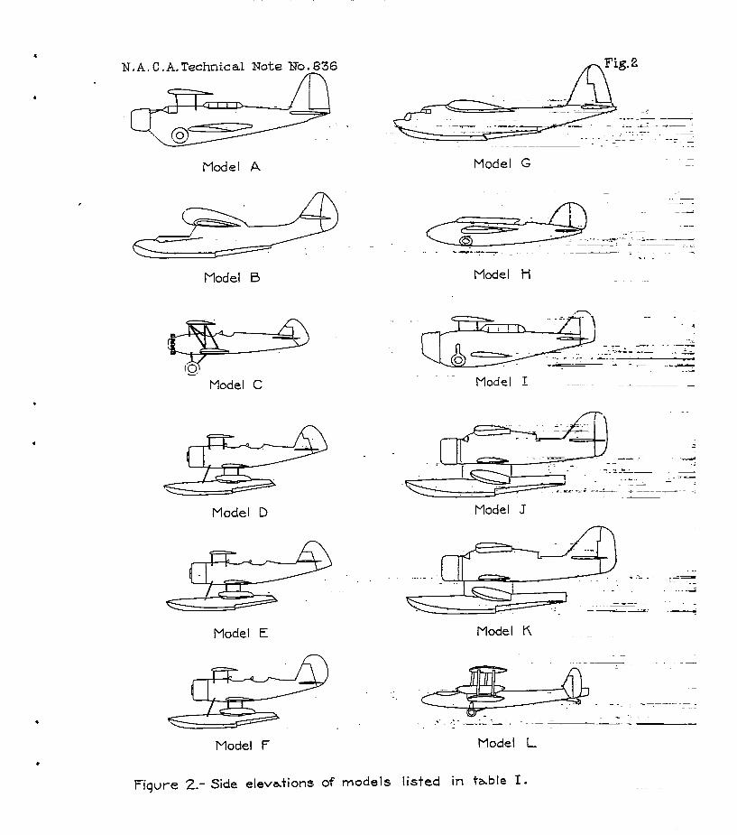
*Fig. 2 N.A.C.A.Technfcal Note XoE6
Model A
Model B
Model C
Model D
Model E
Model F
Model G
Model I
Model J
Model K
Model L
Fiqure 2.- Side elevations of models listed in table I.

. l
-r-7
DU MK-13 Solid, MK-15 Dotied
MK-14
MK-I5A
p-T/O MK- 16
-0 MK-17 Solid, MK-I8 Dotted
.
MK-19
EZO
MK-20
KC MK-21
50 MK-22 Solid, MK-23 tilted
-0
MK-24
.
Fuselaqe No. I
C
Do
Fuselqe Na 2
Fuselage No.3
a --==
Do Fuselzge Na4
c-- l-l
J
Ftiaelaqe No. 5
I
. *
Fuselage No.6
Hull No.7
Hull Na8
Hull No.9
ziga
Hull No.10;
Figure 3.-Sketches of fusdlzqes and t-~-culls listed in table ;lI.
z 9 w

. c . .
I I I I !
.l-
o--
-. 1' -
%, I
dB A
-. 2-
3 4
: $igure 4.- Effect moment
I
0 Data from Washington Wavy Yard. A Data from reference 3.
I
I I
5 6 lf 7 8 9 10
df of fuselage length-depth ratio on rate of change of yawlng- coefficient of fuselage with eidealip.

.Utl
.04 Em I I I
dCnw w
,O
-.ci4
0 10
-
- --
\
20 Angle of dihedral or eweepback,deg.
Figure EL- Effect of &ihadral and sweepback on rate of change. of yawing-moment coefficient of wing with sideslip.