e-pak technology · to airflow, and also permits greater water ... e-pak units utilize totally...
TRANSCRIPT
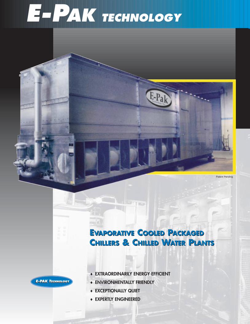
EVAPORATIVE COOLED PACKAGEDCHILLERS & CHILLED WATER PLANTS
E-PAK TECHNOLOGYE-PAK TECHNOLOGY
♦ EXTRAORDINARILY ENERGY EFFICIENT
♦ ENVIRONMENTALLY FRIENDLY
♦ EXCEPTIONALLY QUIET
♦ EXPERTLY ENGINEERED
E-PAK TECHNOLOGY
EVAPORATIVE COOLED PACKAGEDCHILLERS & CHILLED WATER PLANTS
Patent Pending
E-PAK TECHNOLOGYFEATURESEvaporative condensing provides superenergy efficiency. (System EER to 20+)
Helical rotary screw compressors with a 5 year warranty are 4 to 5 times morereliable than reciprocating compressors.
Operating sound level is cut to 50-65dBcompared to an air cooled sound level of 110dB.
Greatest capacity of any packaged chilleron a single skid — shipped via truck inone piece.
APPLICATIONS• Commercial• Residential: Schools/Multifamily• Educational Institutions• Ice Rinks• Thermal Storage• Medium to Low TemperatureProcess —
to 0° Leaving Fluid• Energy Conscious Clients• Can be Designed to Meet Virtually Any
Customer Application
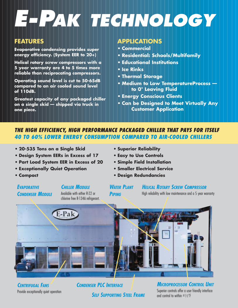
HELICAL ROTARY SCREW COMPRESSORHigh reliability with low maintenance and a 5 year warranty
EVAPORATIVE
CONDENSER MODULE
CHILLER MODULEAvailable with either R-22 or chlorine free R-134A refrigerant.
MICROPROCESSOR CONTROL UNITSuperior controls offer a user friendly interfaceand control to within ±1/2˚FSELF SUPPORTING STEEL FRAME
CENTRIFUGAL FANSProvide exceptionally quiet operation
THE HIGH EFFICIENCY, HIGH PERFORMANCE PACKAGED CHILLER THAT PAYS FOR ITSELF40 TO 60% LOWER ENERGY CONSUMPTION COMPARED TO AIR-COOLED CHILLERS
• 20-535 Tons on a Single Skid• Design System EERs in Excess of 17• Part Load System EER in Excess of 20• Exceptionally Quiet Operation• Compact
• Superior Reliability• Easy to Use Controls• Simple Field Installation• Smaller Electrical Service• Design Redundancies
WATER PLANT
PIPING
CONDENSER PLC INTERFACE

LEADER IN TECHNOLOGY
Table of Contents ___________________________ Evaporative Condensing Advantages ___________________________ Sound Performance Qualities ___________________________ Evaporative Condenser Features ___________________________ Scroll Compressor Features ___________________________ Screw Compressor Features ___________________________ E-Pak Engineering Capabilities ___________________________ Scroll Compressor Chillers DX Evaporator Nominal Ratings 13 General Data 15 Electrical Data 17 General Layout Footprint 17 ____________________________ MagLev Turbo Chillers Flooded Evaporator Nominal Ratings 22 General Data 23 Electrical Data 27 General Layout Footprint 28 _____________________________ Screw Compressor Chillers Flooded Evaporator Nominal Ratings 32 General Data 33 Electrical Data 38 General Layout Footprint 39 ____________________________________ Chilled Water Plants
About E-Pak
E-Pak Technology Inc. produces a line of high quality evaporative cooled package chillers and chilled water plants. These products are revolutionary air-conditioning systems for commercial, industrial and institutional use in the 20 to 530 ton capacity range. While innovative in its application and design, E-Pak prides itself on the use of proven, "State of the Art", high quality components throughout each of its product lines.
Custom Chillers without Custom Costs
With over seventy three (73) models from which to choose, there is an E-Pak Chiller or Chilled Water Plant to meet virtually any application. In addition, E-Pak Technology has the engineering expertise to make an E-Pak Chiller or Chilled Water Plant a perfect fit for your specific application.
Leading Edge, State of the Art Component Technology
In keeping with E-Pak's commitment to the latest technology, E-Pak offers a new multistage, variable speed, centrifugal compressor with Magnetic Levitation bearings. The use of MagLev technology eliminates the metal to metal contact of standard mechanical bearings thereby reducing compressor noise and eliminates the need for lubricating oil which can accumulate in critical refrigeration system heat transfer components reducing system performance. Whether you choose the MagLev Turban or the Helical Rotary Screw compressor each chiller module is equipped with multiple compressors. World Class Components and World Class Service E-Pak provides world-wide installation, warranty and maintenance service in their locality by highly trained technicians through our major component manufacturers. EPA Energy Star Buildings Partner E-Pak's exceptional energy savings and environmentally friendly sound levels and refrigerants have been recognized by the EPA as an "Energy Star Building Partner".
4
5
6
8
9
10
12
19
30
42

4
E-PAK
EVAPORATIVE CONDENSING — THE E- PAK ENERGY ADVANTAGE
POWER DEMAND CONSUMPTION OF AIR COOLED VS THE E-PAK EVAPORATIVE COOLED CHILLER.Note that the peak power demand of the E-PAK product is less than most of the air-cooled minimum demand. The variance in efficiencieswill be greater in conditions where the WB is <78°F and the DB is >95°F.
COOLINGWATER
COILS
AIRFLOW
One of the keys to E-PAK’s unique advantage is evaporative condensers.
While generally applied only in large field erected industrialprocess, refrigeration and air-conditioning systems, evaporative condensers are widely used for condensing refrigerant vapor in mechanical refrigeration systems.
The inherent efficiency of evaporative condensing provides lower condensing temperatures (95 degrees) compared to othercondensing methods, i.e. air cooled (115 degree F to 120 degreesF) or water cooled (105 degrees F) This results in significantlyreduced kW per ton (.70 system kW per ton and 17+ system EER).
Now E-PAK offers the advantage of evaporative condensing on a single skid utilizing world class components.
POWER DEMAND COMPARISON
400.0
350.0
300.0
250.0
200.0
150.0
100.0
50.0
0.0
DEM
AN
D P
OW
ER K
W
Hour of Day in July
1 3 5 7 9
11
13
15
17
19
21
23Air
Evaporative
Based upon 260 ton capacity with 95°F DB and 78°F WB air entering condenser.

EVAPORATOR/COOLER
WATER IN
35˚F
45˚F
WATER OUT
EVAPORATIVECONDENSER
WATER
115˚F
5
EVAPORATIVE CONDENSING - FEATURES & BENEFITS
Simplified Refrigeration Diagram ThatIllustrates How the E-Pak Units Deliver TheirUnique Advantages.
E-PAK CHILLERS OPERATE AT THELOWEST SOUND LEVELS
From <50 dB(A) attenuated to 65 dB(A)
unattenuated vs. air cooled chillers
@ 100 dB(A) to 110 dB(A)
ALL E-PAK UNITS FEATURE MULTIPLE CENTRIFUGAL FANS
Centrifugal fan units operate at lower sound
levels which make this design preferred for
installations where noise is a concern. The
sound they produce is primarily at high fre-
quencies which is easily attenuated by building
walls, windows, and natural barriers.
Additionally, since the sound from the fans is
directional, single sided air entry models can
be turned away from critical areas avoiding a
sound problem. When even quieter operation
is necessary, centrifugal fan models can be
equipped with optional sound attenuation
packages.
OPTIONAL SOUND ATTENUATIONPACKAGES
E-Pak Chillers may be attenuated to sound
levels of >50 dB(A) or lower through
optional packages (see appendix A)
For example, heavy acoustic foam
enclosed by metal double walls
can be factory installed to the
chiller weatherhouse.
However, a condenser sound attenua-
tion package may be field installed after
installation and set-up, if unattenuated sound
levels are determined to be objectionable.
EXCEPTIONALLYQUIET OPERATION
ELECTRONICEXPANSIONVALVE
SCREWCOMPRESSOR
95°F
Forward Curve Centrifugal Fan Wheel
115°F
WEATHER ENCLOSURE
FANS FANS

E-PAK
ELLIPTICAL COIL DESIGNEvaporative Condensers by E-Pak featurea patented coil design which assuresgreater operating efficiency. The ellipticaltube design allows for closer tube spac-ing, resulting in greater surface area perplan area than round tube designs. Inaddition, this design has lower resistanceto airflow, and also permits greater waterloading, making the elliptical coil the mosteffective design available.
CORROSION-RESISTANTMATERIALSThe standard construction of evaporativecooling equipment for many years hasbeen hot-dip galvanized steel. The pur-pose of galvanizing is to protect the base
metal from corrosion, and the thickness of the galvanized layer directly affects theequipment life.
E-Pak unit feature G-235 galvanized steelconstruction. The G-235 designationmeans a minimum of 2.35 ounces of zincper square foot of surface area. This is anincrease of 12% over G-210 galvanizedsteel, and an increase of 160% over G-90galvanized steel used by other manufac-turers, representing the best galvanizationin the industry.
TOTALLY ENCLOSED MOTORSE-Pak units utilize totally enclosed, fan-cooled (TEFC) motors on all fans andpumps. These superior motors, designedto operate in outdoor environments, help
to assure longer equipment life withoutmotor failures, which may result in costlydowntime.
HEAVY DUTY CONSTRUCTIONE-Pak condensers are specially designedand built for the rugged conditions underwhich they must operate. The designincorporates large, heavy-duty panels withdouble-brake flanges and a minimum ofseams to virtually eliminate water leaks.Single brake flanges used in other designsare not as rigid and may permit casingwater leaks.
6
EVAPORATIVE CONDENSERS FROM E-PAK PROVIDE QUALITY CONSTRUCTION AND DESIGN INNOVATIONS
G-235 Galvanized Steel Construction for Superior Corrosion Protection
Double-Brake Flange Joints for SuperiorStrength (much stronger than Single-Brake)
Totally Enclosed (TEFC) Fan Motors WithWeather/Safety Shield
Simplified Non-Clogging Water Distribution System
Exclusive Coil Providing Maximum Efficiency per Plan AreaTotally Enclosed Pump Motor
ROUND TUBE COILS BY OTHERS
ELLIPTICAL COIL BY E-PAK
PVC Drift Eliminators Maximize Water Consumption Efficiency

EVAPORATIVE CONDENSING - FEATURES & BENEFITS
7
Non-Clog E-Pak Water Diffusers
CONDENSINGCOILE-Pak’s condensing coils feature a patent-ed design which assures maximum con-densing capacity. The airflow through thecoil is counterflow to the refrigerant andwater flow, providing the most efficientheat transfer process. This special coildesign is utilized to reduce the air pres-sure drop through the unit while maximiz-ing tube surface area and increasing itsheat transfer capabilities. The uniquelyshaped tubes of the coil are staggered in the direction of air flow to obtain ahigh film coefficient. In addition, all tubesare pitched in the direction of refrigerantflow to give good drainage of liquidrefrigerant.
The coils are manufactured from highquality steel tubing following the moststringent quality control procedures. Each circuit is inspected to assure thematerial quality and then tested beforebeing assembled into a coil. Finally, theassembled coil is tested at 350 P.S.I.G. air pressure under water to make sure it is leak free.
To protect the coil against corrosion, it is placed in a heavy-duty steel frame and the entire assembly is dipped inmolten zinc (hot-dip galvanized) at a temperature of approximately 800°F.
FORCE DRAFT CONDENSERE-PAK condensers are designed for forced draft air flow which locates the fan motors in the dry inlet air stream,thereby increasing motor reliability overinduced draft designs used by other man-ufacturers which locate the fan motors inthe wet discharge air stream.
WATER DISTRIBUTION SYSTEMAnother important part of an evaporativecondenser is the water distribution system.In order to give the maximum heat trans-fer and minimize scaling, the coil must be drenched with water at all times. The E-Pak system does this by circulatingapproximately 6 gallons of water perminute over every square foot of coil face area.
The water distribution system is greatlysimplified in E-Pak units, with the largestnon-clog water diffusers (see below)available for evaporative condensers. Thediffusers are threaded into the water dis-tribution header to ensure correct position-ing. Also, a collar on the diffuser extendsinto the header and acts as an anti-sludgering to reduce the need for maintenance.Excellent flooding of the coil is maintainedat all times without numerous small orifice nozzles.
For corrosion protection the diffusers are made of ABS plastic and distributor pipesare noncorrosive Polyvinyl Chloride (PVC).
PVC DRIFT ELIMINATORSThe final element in the upper part of the condenser are moisture eliminatorswhich strip the entrained water dropletsfrom the leaving air stream. E-Pak unitsfeature patented eliminators that areapproximately 5" deep, spaced on 1" centers. They incorporate a hookedleaving edge designed to direct the dis-charge air stream away from the fans to help eliminate recirculation of hot, saturated air back into the fan intake.
E-Pak eliminators are constructed entirelyof inert, corrosion-free PVC. This PVCmaterial has been specially treated toresist damaging ultraviolet light. The eliminators are assembled in easily han-dled sections to facilitate removal therebyexposing the upper portion of the unit and water distribution system for periodicinspection and maintenance.

E-PAK
QUIET AND SMOOTHOPERATIONQuiet operation is due in part to journalbearings which transmit less noise fromthe running gear to the shell. Additionally,the fixed throw eliminates the possibility of scroll impact and the resulting noise.The check valve closes fast and seals tightfor quiet shutdown at 1M.
DURABILITY/EXTENDED LIFEMany features contribute to durability andlong life.
A motor tube design is used. The motorand lower bearing head are both locatedin a steel tube bolted to the housing. Thisarrangement provides for a more precisemotor and bearing alignment and permitsthe suction gas to enter the shell prior toflowing through the motor. The velocity ofthe suction gas decreases as it enters theshell, allowing the dirt particles to dropout and settle in the sump.
The compressor has a built-in dirt separa-tor/trap in the lower bearing head to prevent dirt from reaching the bearings.
The high-volume oil sump helps preventexcessive oil loss that can occur in systemswith large refrigerant charges. This highvolume oil sump and large suction volumealso help minimize the oil dilution andslugging that occur during periods offlooding.
Also, the use of cast iron for both theorbiting and fixed scrolls provides greaterstrength and galling resistance.
8
E-PAK’S SCROLL COMPRESSORS PROVIDE QUIET, EFFICIENT, AND RELIABLE OPERATION IN E-PAK CHILLERS
Oil charging valve for changing or adjusting oil level.
Large discharge gas volumefor lower pressure pulsation.
High strength cast iron fixedand orbiting scroll, resulting in less thermal distortion, lessleakage and higher efficiency.
Fixed throw prevents scrollimpact and resulting noise.
Motor tube for more accuratelower bearing alignment. Also,permits suction gas to entershell prior to flowing throughand cooling the motor. Dirtparticles will then drop out and settle in the sump.
High efficiency motor for lower energy consumption.EERs up to 11.5.
High volume oil sump main-tains lubrication during periodsof high oil carry-over.
Dirt separator for maximum bearing life.
Improved check valve — forquiet shutdown and less flowrestriction.
Reverse vent to prevent scrolldamage during reverse rota-tion cause by improper phaseconnection.
Optimized involute geometryfor for higher efficiency.
Journal bearings for low noise.
Internal motor temperature sensor is part of field-proven protection system.
Sight glass to monitor oil level.

9
Revolutionary Design, Tried and Proven Performance and Reliability. Now you can have superior Compressor efficiency, reliability and quality in one twin-screw compressor with high-performing design combined with vast refrigeration and cooling industry experience and manufactured with the sophisticated technology of the world's largest refrigeration company. When used in your equipment, the screw compressor gives you unparalleled operating costs, reliability and ease of application. Best Full-Load and Part-Load Efficiencies. The Screw compressor was designed to meet your most challenging needs now, and well into the future. The capacity modulation in the Carlyle compressor has been designed to provide infinitely variable capacity from 25% to 100% for perfect load matching and superior part-load efficiency. Reduced tip speeds provide lower radiated sound and improved sound quality too.
Unequaled Performance 40 to 250-ton sizes for R-134a air-conditioning and medium-temperature applications. Patented rotor profile geometry produced on state-of-the-art manufacturing processes.
Perfect Load Matching Continuous unloading down to 25%. Built-in Vi compensation at part load. Automatic unloaded starting. Simple dual-solenoid control.
Service friendly; semi-hermetic with simple disassembly and reassembly.
Screw Compressor Technology

With over 73 different package chillermodels to choose from, there is an E-PAK Chiller for virtually any application.However, E-PAK Technology’s staff of engineers can provide further assistanceand engineering capabilities to providethe best possible match to your specificapplication. Some of the more commonlyrequested engineered solutions for specificapplications are described in the subse-quent sections below.
SPECIAL OR COMPACT SITELIMITATIONSE-PAK Technology can successfully accom-plish installations of their Chillers whensize is of critical importance. Through creative component installation, E-PAK’sengineers have been able to make stan-dard units smaller upon customer request.
For example E-PAK Technology recentlycompleted a 265 ton package chilledwater plant which was required to fit within a space 16' wide and 26' inlength. E-PAK was additionally challengedto install duplex condenser water andchilled water pumps on the same unit. Inline chilled water pumps were installedoverhead in the unit to save space, allow-ing for the entire chilled water plant to beplaced on a single skid measuring only 8'by 24'. By modifying a standard configu-ration for this type of chilled water plant,E-PAK’s engineers were able to successful-ly satisfy the requirements of this client toproduce a product that performs flawlessly.
In addition to space requirements someinstallations also introduce other challeng-ing chiller placements. For example, pits or placements with high surroundingwalls pose problems. These circumstancesoften do not permit the free flow of inletair to the condenser, thereby creating performance problems. In these instances, E-PAK engineers have been able toinclude discharge hoods that inhibit theshort circuiting of discharge air back to
E-PAK
10
E-PAK’S TECHNOLOGY… ENGINEERING CAPABILITIES TO MEET CLIENT NEEDS
One-piece rigging for ease of installation.
Princeton, New Jersey — 300 ton Chilled Water Plant with sound attentuation and plume abatement coil (hot gas de-superheat coil which runs the length of the condenser).

the fair intake airways, thereby maintain-ing the unit's efficiency.
REDUNDANT CONDENSERRECIRCULATION WATER PUMPSThese recirculation water pumps can be added to enhance the equipment’s reliability.
E-PAK’s engineers can locate these redundant pumps on opposite sides of the condenser or when space limitationsexist inside the aluminum chiller cabinetfor further versatility.
CHILLER CONDENSER SOUNDATTENUATIONWhile the E-PAK Chiller units and ChilledWater Plants already provide exceptional-ly quiet operation, E-PAK engineers can further reduce the sound levels by addingsound attenuation packages. E-PAK engi-neers have devised special double wallpanels containing sound attenuating material that can be placed in the cabinet.In addition, special condenser intake anddischarge sound traps can be applied tothe units to further reduce sound levels tobelow 50dB(A) at 50'.
PHYSICAL SITE LIMITED ACCESSAND WEIGHT LIMITATIONSE-PAK engineers have devised specialways to tackle almost any installationproblem. When the physical arrange-ments of a site limit crane access, or whenweight limitations do not allow the com-plete equipment to be rigged as one unit,E-PAK engineers have a solution. E-Pak has designed special flanged connections that permit the equipment to be separated at the site, placed in the assigned location, refrigerant linesconnected, and the unit operated with little delay.
COST LIMITING FACTORSE-PAK engineers understand that certainapplications require special cost limitingfactors to be applied. E-PAK engineerscan modify the component designations to result in higher condensing tempera-tures and lower first costs. This enablesowners or contractors to minimize the cost of the package chiller and chilledwater plant yet still reap the rewards ofthe energy efficient E-PAK equipment.
ENGINEERING ADVANTAGES
11
Flanged connectors allow for optional2-piece rigging to meet specialinstallation requirements.
A completed unit ready to be shipped from E-Pak's manufacturing facility.
12
E-PAK
GENERALThe chiller is an evaporative cooled chillercompletely packaged on a self-supportingstructural steel frame with all refrigerantpiping and interconnecting power andcontrol wiring installed and tested by themanufacturer prior to shipment.
The chiller is suitable for outdoor installa-tion with all chiller components enclosedin a protective aluminum weather housingand all unprotected system componentssuitable for outdoor operation.
The chiller has a minimum system energyefficiency ratio (EER) including compres-sors, condenser fan(s), condenser pumpand control power and a system energyconsumption rate as specified in the chillerequipment schedule.
The chiller performance is rated in accordance with ARI standard 590.
CHILLEREach chiller module is factory assembledand equipped with a minimum of twodirect drive 3600 rpm, hermetic scrollcompressors suitable for operation with R-22 refrigerant. (20 to 35 tons - 2 compressors/1 circuit - 40 to 60 tons -4 compressors/2 circuits). Tandum Chillermodels are equipped with (2) chiller modules on 3 or 4 circuits with 6 to 8
compressors. No compressor is largerthan 15 HP. Each compressor has: cen-trifugal oil pump, oil level sightglass, oilcharging valve, two point lubrication foreach motor bearing, flooded lubricationfor the journal and thrust bearings, and a check valve on the scroll discharge port.
Motor is suction gas cooled, hermeticallysealed, two-pole, squirrel cage inductiontype.
EVAPORATORShell and tube design with seamless cop-per tubes roller expanded into tube sheets.Designed, tested, and stamped in accor-dance with ASME code for refrigerantside working pressure of 300 psig. Waterside working pressure is 300 psig. Onewater pass with a series of internal baf-fles. Each shell includes drain connections,entering and leaving temperature sensors,and 3/4-inch Armaflex II (or equal) insulation (K = 0.26).
REFRIGERANT CIRCUITAll refrigeration circuits are completelyindependent and include liquid line anddischarge line service valves, filter dryer,combination moisture indicator-sightglass,charging port, insulated suction line, liquid line solenoid valve and thermalexpansion valve.
Isolation valves provide means of isolatingrefrigerant charge in either the high orlow pressure side while servicing. Onerefrigerant circuit on 20 to 35 tons; tworefrigerant circuits on 40 to 60 tons. Eachrefrigerant circuit will be pressure tested,evacuated and shipped with a completecharge of compressor oil and a holdingcharge at 30psi of refrigerant R-22.
CONTROL PANELEach chiller module is furnished with aFactory-mounted microprocessor basedcontrol panel which uses 120/60/1power. Automatic shutdown protectionwith manual reset is provided for lowevaporator outlet refrigerant temperatureand pressure, high condenser refrigerantpressure, high motor winding tempera-ture, motor current overload, and phasereversal. Automatic shutdown protectionwith automatic reset after condition is corrected is provided for low line voltageand loss of chilled water flow.
CAPACITIES FROM 20 TONS TO 60 TONSTANDUM UNITS AVAILABLE
CAPACITIES FROM 65 TONS TO 120 TONS
MULTIPLE FULLY HERMETIC SCROLL COMPRESSORS10 HP & 15 HP EACH
LOW MCA ALLOWS MORE CAPACITY ON SMALLER ELECTRICAL SERVICE
EVAPORATIVE COOLED DX EVAPORATORSCROLL COMPRESSOR PACKAGED CHILLERS

13
MODEL CAPACITY COMPRESSOR SYSTEM SYSTEM SYSTEM TOTAL HEATNUMBER TONS kW KW KW/TON EER OF REJECTION
SINGLE PACKAGES
ECT-20-036 21.6 14.7 18.2 0.84 14.24 309.4
ECT-25-048 26.0 19.7 23.1 0.89 13.51 379.3
ECT-30-048 30.7 23.5 27.0 0.88 13.64 448.7
ECT-40-070 43.0 29.6 37.1 0.86 13.91 617.1
ECT-50-090 50.6 38.4 43.9 0.87 13.83 738.3
ECT-60-100 61.6 47.4 55.0 0.89 13.44 901.1
TANDEM PACKAGES
ECT-65-4870 69.0 49.3 60.30 0.87 13.73 996.4
ECT-70-4870 73.7 53.1 64.10 0.87 13.80 1,065.7
ECT-80-70T 86.0 59.2 74.20 0.86 13.91 1,234.2
ECT-90-90T 93.6 68.0 79.00 0.84 14.22 1,355.4
ECT-100-100T 101.2 76.8 87.80 0.87 13.83 1,476.7
ECT-110-100T 112.2 85.8 101.00 0.90 13.33 1,639.4
ECT-120-100T 123.2 94.8 110.00 0.89 13.44 1,802.1
*Nominal ratings based on 44°F leaving water temperature, 10°F ∆T, 78°F wet bulb temperature.
SCROLL COMPRESSOR CHILLERS — DX EVAPORATOR
NOMINAL RATINGS* DX EVAPORATOR SCROLL CHILLERS
The unit control module (UCM) automati-cally takes action to prevent completeshutdown by shedding compressors oneat a time. This occurs in the event of low
evaporator refrigerant temperature, highcondenser refrigerant pressure, or motorcurrent overload, thus preventing themotor current from exceeding setpoint.
Solid-state chilled water temperature sen-sors are included for precise and accuratecontrol. A menu driven display indicatesthe operating code, the last diagnosticcode, chilled water setpoint, current limitsetpoint, condenser water and chilledwater temperature sensors. Factory-installed entering and leaving condenserwater temperature sensors (optional) areavailable for microprocessor display or
Trane Tracer monitoring. Over 40 diagnostic checks are made and will be displayed when a problem is detected.
STARTERThe unit control panel contains both a control section and a starter section. The panel is painted, NEMA 1 enclosure.The starter section contains: top access for power wiring, single point powerhook-up, three-phase solid-state overloadprotection, customer wired grounding lug,and control power transformer with fusedprotection.
CONDENSERThe chiller unit is equipped with a forceddraft multi-circuit evaporative condenserwhich is selected to provide the heat ofrejection capacity required by the chillerat the specified condition.
PAN & CASINGThe pan and casing are constructed of G-235 hot dip galvanized steel.
The pan/fan section include fan(s) withmotors and drives mounted and alignedat the factory. Fan motors are totallyenclosed and fan cooled. The motors and weather safety shields are removedfor shipping and field installation.
Standard pan accessories include circu-lar access doors, stainless steel strainers,waste water bleed line with adjustablevalve and brass make-up valve with anunsinkable foam filled plastic float.

E-PAK
14
CENTRIFUGAL FANSThe fans are forward curved centrifugaltype of hot dip galvanized construction.The fans are factory installed to thepan/fan section, statically and dynamical-ly balanced. The fans are mounted oneither a solid or hollow steel shaft withforged journal bearings. The fan shaft issupported by heavy duty, self-aligningbearings with cast-iron housings andlubrication fittings for maintenance.
The fan drive(s) is V-Belt type with taperlock sheaves designed for 150% of themotor nameplate horsepower. The drive(s)are mounted and aligned at the factory.
FAN MOTORTotally enclosed fan cooled motor(s) with a 1.15 service factor (inverter duty typewith a 1.25 service factor when used inconjunction with a variable frequencydrive) are furnished suitable for outdoorservice. Motor(s) are mounted on anadjustable base. The motors are mounted,wired and tested at the factory, thenremoved to comply with shipping restric-tions, with all motor leads clearly taggedfor ease of hook up at the installation site.
HEAT TRANSFER COILThe coil is constructed entirely of primesurface steel, encased in steel frameworkwith the entire assembly hot-dip galva-nized after fabrication. Coil is designedwith sloping tubes for free drainage of liquid refrigerant and tested to 350 psigair pressure under water. Each coil circuitis sized for the heat of rejection capacityof each individual refrigerant circuit. The coil features elliptical tube designwhich permits greater water loading,lower air flow resistance and higher heat transfer efficiency. Optional copper or stainless steel coils are also available.
WATER DISTRIBUTION SYSTEMThe system provides a water flow rate of not less than 6 GPM over each squarefoot of unit face area to ensure properflooding of the coil. The spray header isconstructed of schedule 40, PVC pipe forcorrosion resistance. All spray branchesare removable and include a threadedend plug for cleaning. The water is distributed over the entire coil surface by precision molded ABS spray nozzles(1" x 1/2" orifice) with internal anti-sludge rings to eliminate clogging.Nozzles are threaded into spray headerto provide easy removal for maintenance.
WATER RECIRCULATION PUMPThe pump is a close-coupled, bronze fitted, centrifugal type with mechanicalseal, installed vertically at the factory toallow free drainage on shut down. Thetotally enclosed, motor is furnished suit-able for outdoor service.
ELIMINATORSThe eliminators are constructed entirely of PVC that has been specially treated toresist ultra-violet light. Assembled in easilyhandled sections, the eliminator bladesare spaced on 1-inch centers and incor-porate three changes in air direction toassure removal of entrained moisture from the discharge air stream. They have a hooked leaving edge to direct the discharge air away from the fans to minimize recirculation.
FINISHAll pan and casing materials shall be constructed of G-235 heavy gauge millhot-dip galvanized steel for maximumprotection against corrosion. During fabri-cation, all panel edges shall be coatedwith a 95% pure zinc-rich compound.
WEATHER HOUSINGThe chiller weather housing is constructedof 0.080 thick mill finished aluminum and is equipped with stainless steel, piano hinged access doors and lift-offpanels to provide maximum accessibilityto the chiller components for service and maintenance. All access doors are double-wall construction.
The weather housing roof is sectionallyconstructed for removal for crane accessto the compressors. The roof is sloped for water and snow runoff and capable of supporting a 35 lb./sq. foot snow loadwhere required.
OPTIONSSee Appendix A for additional optionspecifications.

15
SCROLL COMPRESSOR CHILLERS — DX EVAPORATOR
NOMINAL CHILLER SIZE 20 25 30 40 50 60
CHILLER MODULES 1 1 1 1 1 1
COMPRESSORS Scroll Scroll Scroll Scroll Scroll Scroll
QUANTITY 2 2 2 4 4 4
NOMINAL SIZE (HP) (2)10 (1)10/(1) 15 (2)15 (4)10 (2)10/(2)15 (4) 15
EVAPORATOR
QUANTITY 1 1 1 1 1 1
TYPE DX S&T DX S&T DX S&T DX S&T DX S&T DX S&T
NO. CIRCUITS 1 1 1 2 2 2
WATER STORAGE (GAL) 12 11 16 13 21 19
WATER STORAGE (LITERS) 45 42 61 49 80 72
MINIMUM FLOW (GPM) 24 30 36 48 60 72
MINIMUM FLOW (LPS) 1.5 1.9 2.3 3.0 3.8 4.5
MAXIMUM FLOW (GPM) 72 90 108 144 180 216
MAXIMUM FLOW (LPS) 4.5 5.7 6.8 9.1 11.4 13.6
CONDENSER 36 48 48 70 90 100
QUANTITY 1 1 1 1 1 1
TYPE Evaporative Evaporative Evaporative Evaporative Evaporative Evaporative
NO. CIRCUITS 1 1 1 2 2 2
FAN TYPE VBD/FC VBD/FC VBD/FC VBD/FC VBD/FC VBD/FC
FAN QUANTITY 2 2 2 2 3 3
FAN MOTOR QUANTITY 1 1 1 1 1 1
FAN MOTOR TYPE TEFC TEFC TEFC TEFC TEFC TEFC
FAN MOTOR SPEED STANDARD Single Spd Single Spd Single Spd Single Spd Single Spd Single Spd
OPTION 2Spd/VFD 2Spd/VFD 2Spd/VFD 2Spd/VFD 2Spd/VFD 2Spd/VFD
FAN MOTOR (HP) 3.0 3.0 3.0 5.0 5.0 7.5
PUMP MOTOR (HP) 0.75 0.75 0.75 0.75 1 1
SUMP HEATER (kW) 2kW 2kW 2kW 2kW 3kW 3kW
WATER LEVEL CONTROL Float valve Float valve Float valve Float valve Float valve Float valve
SOUND LEVEL dB(A)* 52 52 52 58 55 57
LOW ABMIENT (F) Condenser 0 0 0 0 0 0
% MINIMUM SYSTEM LOAD 50 40 50 25 20 25
REFRIGERANT R-22 R-22 R-22 R-22 R-22 R-22
REFRIGERANT CHARGE (LBS) 150 200 200 225 300 300
REFRIGERANT CHARGE (kG) 68 91 91 102 136 136
UNIT DIMENSIONS (FT) 8 x 12 8 x 12 8 x 12 8 x 12 8 x 12 8 x 12
OPERATING WEIGHT (LBS) 5,904 6,611 6,883 7,743 9,803 10,198
OPERATING WEIGHT (kG) 2,678 2,998 3,122 3,512 4,446 4,625
SHIPPING WEIGHT (LBS) 4,754 5,411 5,683 6,518 8,503 8,898
SHIPPING WEIGHT (kG) 2,156 2,454 2,577 2,956 3,856 4,035
*dB(A) = Sound Pressure level (SPL) Per ANSI S12.34-1988 @ High Speed Condenser FanNoise sources are recorded under free field conditions over a reflecting plane @ 50 ft.
GENERAL DATA ECT 20-60

16
E-PAK
NOMINAL CHILLER SIZE 65 70 80 90 100 110 120
CHILLER MODULES 2 2 2 2 2 2 2
COMPRESSORS Scroll Scroll Scroll Scroll Scroll Scroll Scroll
QUANTITY 6 6 8 8 8 8 8
NOMINAL SIZE (HP) (5)10/(1)15 (2)10/(2)15 (8)10 (6)10/(2)15 (4)10/(4)15 (2)10/(6)15 (8)15
EVAPORATOR
QUANTITY 2 2 2 2 2 2 2
TYPE DX S&T DX S&T DX S&T DX S&T DX S&T DX S&T DX S&T
NO. CIRCUITS 3 3 4 4 4 4 4
WATER STORAGE (GAL) 24 29 26 34 42 40 38
WATER STORAGE (LITERS) 91 110 98 129 160 152 144
MINIMUM FLOW (GPM) 78 84 96 108 120 132 144
MINIMUM FLOW (LPS) 4.9 5.3 6.0 6.8 7.6 8.3 9.0
MAXIMUM FLOW (GPM) 234 252 288 324 360 396 432
MAXIMUM FLOW (LPS) 14.8 15.9 18.2 20.5 22.8 25.0 27.2
CONDENSER 48 70 48 70 70T 90T 90T 100T 100T
QUANTITY 2 2 2 2 2 2 2
TYPE Evaporative Evaporative Evaporative Evaporative Evaporative Evaporative Evaporative
NO. CIRCUITS 3 3 4 4 4 4 4
FAN TYPE VBD/FC VBD/FC VBD/FC VBD/FC VBD/FC VBD/FC VBD/FC
FAN QUANTITY 4 4 4 6 6 6 6
FAN MOTOR QUANTITY 2 2 2 2 2 2 2
FAN MOTOR TYPE TEFC TEFC TEFC TEFC TEFC TEFC TEFC
FAN MOTOR SPEED STANDARD Single Spd Single Spd Single Spd Single Spd Single Spd Single Spd Single Spd
OPTION 2Spd/VFD 2Spd/VFD 2Spd/VFD 2Spd/VFD 2Spd/VFD 2Spd/VFD 2Spd/VFD
FAN MOTOR (HP) 3 & 5 3 & 5 (2) 5 (2) 5 (2) 5 (2) 7.5 (2) 7.5
PUMP MOTOR (HP) 2 2 2 2 2 2 2
SUMP HEATER (kW) (2) 2kW (2) 2kW (2) 2kW (2) 3kW (2) 3kW (2) 3kW (2) 3kW
WATER LEVEL CONTROL Float valve Float valve Float valve Float valve Float valve Float valve Float valve
SOUND LEVEL dB(A)* 58 58 58 55 55 57 57
LOW ABMIENT (F) Condenser 0 0 0 0 0 0 0
% MINIMUM SYSTEM LOAD 15 15 12.5 12.5 10.0 10.0 12.5
REFRIGERANT R-22 R-22 R-22 R-22 R-22 R-22 R-22
REFRIGERANT CHARGE (LBS) 425 425 450 525 600 600 600
REFRIGERANT CHARGE (kG) 193 193 204 238 272 272 272
UNIT DIMENSIONS (FT) 8 x 12 8 x 12 8 x 12 8 x 12 8 x 12 8 x 12 8 x 12
OPERATING WEIGHT (LBS) 14,400 14,625 15,500 17,500 19,600 20,000 20,400
OPERATING WEIGHT (kG) 6,510 6,635 7,025 7,958 8,890 9,070 9,250
SHIPPING WEIGHT (LBS) 12,000 12,200 13,035 15,020 17,000 17,400 17,800
SHIPPING WEIGHT (kG) 5,410 5,530 5,910 6,810 7,710 7,890 8,070
*dB(A) = Sound Pressure level (SPL) Per ANSI S12.34-1988 @ High Speed Condenser FanNoise sources are recorded under free field conditions over a reflecting plane @ 50 ft.
GENERAL DATA ECT 65-120

COMPRESSORS FAN MOTOR(S) PUMP(S) POWER
200/230V 460VQty. HP HP HP HP HP HP HP HP Qty. HP Qty. HP RLA MCA MOP RLA MCA MOP
ECT-20-036 2 10 10 N/A N/A N/A N/A N/A N/A 1 3 1 3/4 84 92 125 35 39 45
ECT-25-048 2 10 15 N/A N/A N/A N/A N/A N/A 1 3 1 3/4 102 115 150 44 50 60
ECT-30-048 2 15 15 N/A N/A N/A N/A N/A N/A 1 3 1 3/4 120 133 150 53 59 70
ECT-40-070 4 10 10 10 10 N/A N/A N/A N/A 1 5 1 3/4 158 167 175 66 69 80
ECT-50-090 4 10 15 10 15 N/A N/A N/A N/A 1 5 1 1 194 217 250 84 90 100
ECT-60-100 4 15 15 15 15 N/A N/A N/A N/A 1 7.5 1 1 238 254 300 105 111 125
ECT-65-4870 6 10 10 10 10 10 15 N/A N/A 2 3/7.5 2 3/4-3/4 265 278 300 112 118 125
ECT-70-4870 6 10 10 10 10 15 15 N/A N/A 2 3/7.5 2 3/4-3/4 283 296 300 121 127 150
ECT-80-70T 8 10 10 10 10 10 10 10 10 2 7.5/7.5 2 3/4-3/4 329 337 350 137 141 150
ECT90-90T 8 10 15 10 15 10 10 10 10 2 5/5 2 1\1 352 365 400 149 155 175
ECT100-90T 8 10 15 10 15 10 15 10 15 2 5/5 2 1\1 388 401 450 167 173 175
ECT-110-100T8 8 15 15 15 15 10 15 10 15 2 7.5/7.5 2 1\1 439 452 500 192 198 200
ECT-120-100T8 8 15 15 15 15 15 15 15 15 2 7.5/7.5 2 1\1 475 488 500 210 216 225
Notes: Electrical ratings are based upon nominal chiller ratings (44°F LWT, 10° ∆T, 78°F WB) with a single point power distribution center furnished by E-PAK.RLA = System Running Load Amps, includes compressors, condenser fans and pump motor.MCA = Minimum circuit ampacity, includes compressors, condenser fans and pump motor.MOP = Maximum Overcurrent Protection, includes compressors, condenser fans and pump motor.
SCROLL COMPRESSOR ELECTRICAL DATA
17
SCROLL COMPRESSOR CHILLERS — DX EVAPORATOR
ECT 20-036, ECT 25-048, ECT 30-048
��
8'
8'
7'- 8"
8'1'- 3.125'

18
E-PAKECT 40-070
���
ECT 50-90, 60-100
�
9'
8'
8' - 3.425"
8'
1' - 3.125"
10'- 2"
8'
8' - 3.625"
8'
9'
1' - 3.125"
19
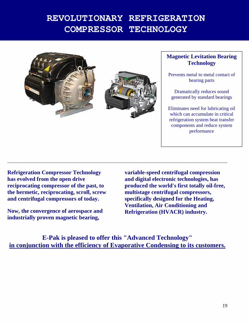
__________________________________________________________________________________________ Refrigeration Compressor Technology has evolved from the open drive reciprocating compressor of the past, to the hermetic, reciprocating, scroll, screw and centrifugal compressors of today. Now, the convergence of aerospace and industrially proven magnetic bearing,
variable-speed centrifugal compression and digital electronic technologies, has produced the world's first totally oil-free, multistage centrifugal compressors, specifically designed for the Heating, Ventilation, Air Conditioning and Refrigeration (HVACR) industry.
E-Pak is pleased to offer this "Advanced Technology"
in conjunction with the efficiency of Evaporative Condensing to its customers.
REVOLUTIONARY REFRIGERATION COMPRESSOR TECHNOLOGY
Magnetic Levitation Bearing Technology
Prevents metal to metal contact of
bearing parts
Dramatically reduces sound generated by standard bearings
Eliminates need for lubricating oil which can accumulate in critical refrigeration system heat transfer components and reduce system
performance

20
General: The chiller shall be an evaporative cooled chiller completely packaged on a self-supporting structural steel frame with all refrigerant piping and interconnecting power and control wiring installed and tested by the manufacturer prior to shipment. The chiller shall be suitable for outdoor installation with all chiller components enclosed in a protective aluminum weather housing and all unprotected system components shall be suitable for outdoor operation. The chiller has a minimum system energy efficiency ratio (EER) including compressors, condenser fan(s), condenser pump and control power and a system energy consumption rate as specified in the chiller equipment schedule. The chiller performance shall be rated in accordance with ARI standard 590. Chiller: Each chiller module is factory assembled and equipped with a totally oil free direct-drive variable speed centrifugal compressor suitable for operation with R-134A refrig-erant, with the following features:
Integral variable-speed motor control provides continuous adjustments in compressor speed, providing optimum energy efficiency throughout varying load conditions, while maintaining close temperature control.
Soft Start limits initial inrush
current to 2 amps reducing energy demand and extending the life of the motor windings. Magnetic “friction free”
bearings eliminate the inefficiencies of friction heat of mechanical bearings and eliminates the need for oil in the refrigerant. Oil free operation eliminates
inefficiencies and a need for oil management system. Low operating noise level of
71 dBA @ 1 M. Integrated computer control
providing 79 points of
diagnostic and operational control. Evaporator: Each chiller module will be equipped with a Stainless Steel Brazed Plate Evaporator designed, tested and stamped in accordance with ASME pressure vessel code rated for a maximum working pressure of 450 psig. Sub-Cooler: Each refrigerant circuit shall be equipped with a patented suction to liquid heat-exchang-er which shall provide the necessary sub-cooling of the liquid refrigerant and super-heating of the suction refrigerant gas while enhancing the effectiveness of the evaporator. Refrigerant circuit: Each circuit liquid & suction line service valves, filter drier, combination moisture indicat-or/sightglass, electronic expan-sion valve, charging valve and insulated suction lines. Low side relief valves are provided for each circuit (300psi).Each refrigerant circuit will be pressure tested, evacuated and shipped with a complete operating charge of refrigerant R-134A
EVAPORATIVE COOLED OIL-FREE CENTRIFUGAL
COMPRESSOR PACKAGED CHILLERS CAPACITIES FROM 60 TONS TO 550 TONS

21
Control Panel: Each chiller module control panel will be equipped with: Rotary circuit breaker for each compressor provides compressor protection and isolation for easy maintenance. 24 VDC control circuit. C-UL 508A panel constructi-on Control panel ventilation fan to extend component life and provide reliable operation. All sensors mounted, wired and tested.
PLC Control System: The PLC will monitor,
control and maintain stable chiller operation through an array of sensors, actuators, relays, switches and control algorithms. Multiple Proportional Intigral
Derivative (PID) temperature control loops ensure reliable, stable and efficient operation by institanious response to fluctuating system loads. Predictive control loop to
maintain stable operation under low load and batch loading conditions typical of industrial process cooling conditions. Durable 6 inch TFT color
touch-screen Human Machine Interface (HMI) provides extensive diagnostic and operational information, safeties, alarms and faults. Clear language text display.
Condenser: The chiller unit shall be equipped with a forced draft multi-circuit evaporative condenser which is selected to provide the heat of rejection capacity required by the chiller at the specified condition. Pan & Casing: The pan and casing shall be constructed of G-235 hot dip galvanized steel. The pan/fan section shall include fan(s) with motors and drives mounted and aligned at the factory. The motors and weather safety shields will be removed for shipping to be reinstalled in the field. Standard pan accessories shall include circular access doors, stainless steel strainers, waste water bleed line with adjustable valve and brass make-up valve with an unsinkable foam filled plastic float. Centrifugal Fans: The fans will be forward curved centrifugal type of hot dip galvanized construction. The fans will be factory installed to the pan/fan section, statically and dynamically balanced. The fans shall be mounted on either a solid or hollow steel shaft with forged journal bearings. The fan shaft shall be supported by heavy duty, self-aligning bearings with cast-iron housings and lubrication fittings for maintenance.
The fan drive(s) shall be V- Belt type with taper lock sheaves designed for 150% of the motor nameplate horsepower. The drive(s) are to be mounted and aligned at the factory. Fan Motor: Totally enclosed fan cooled motor(s) with a 1.15 service factor (inverter duty type motor with a 1-25 service factor when used in conjuction with a variable frequency drive) shall be furnished suitable for outdoor service. Motor(s) shall be mounted on a adjustable base. The fan motor shall be mounted, wired and tested at the factory then removed for shipment and shipped with the unit for remounting by the installer. All wiring will be clearly tagged for ease of hookup. Heat Transfer Coil: The coil shall be all prime surface steel, encased in steel framework with the entire assembly hot-dip galvanized after fabrication. Coil shall be designed with sloping tubes for free drainage of liquid refrigerant and tested to 350 psig air pressure under water. Each coil circuit will be sized for the heat of rejection capacity of each individual refrigerant circuit. The coil will feature elliptical tube design which permits greater water loading, lower air flow
Oil-Free Centrifugal Chillers - Flooded Evaporator
CAPACITIES FROM 60 TONS TO 550 TONS

22
22 resistance and higher heat transfer efficiency. Water Distribution System: The system shall provide a water flow rate of not less than 6 GPM over each square foot of unit face area to ensure proper flooding of the coil. The spray header shall be constructed of schedule 40, PVC pipe for corrosion resistance. All spray branches shall be movable and include a threaded end plug for cleaning. The water shall be distributed over the entire coil surface by precision molded ABS spray nozzles (1" x 1/2" orifice) with internal anti-sludge rings to eliminate clogging. Nozzles shall be threaded into spray header to provide easy removal for maintenance.
Water Recirculation Pump: The pump shall be a close-coupled, bronze fitted, centrifugal type with mechanical seal, installed vertically at the factory to allow free drainage on shut down. The totally enclosed, motor shall be furnished suitable for outdoor service. Eliminators: The eliminators shall be constructed entirely of PVC that has been specially treated to resist ultra-violent light. Assembled in easily handled sections, the eliminator blades shall be spaced on 1-inch centers and shall incorporate three changes in air direction to assure removal of entrained moisture from the discharge air stream. They shall have a hooked leaving edge to direct the discharge air away from the fans to minimize recirculation.
Finish: All pan and casing materials shall be constructed of G-235 heavy gauge mill hot-dip galvanized steel for maximum protection against corrosion. During fabrication, all panel edges shall be coated with a 95% pure zinc-rich compound. Weather Housing: The chiller weather housing shall be constructed of 0.080 thick mill finished aluminum and shall be equipped with piano hinged access doors and lift-off panels to provide maximum accessability to the chiller components for service and maintenance. The weather housing roof shall be sectionally constructed for removal for crane access to the compressors, The roof shall be slopped for water and snow runoff and capable of supporting a 35 lb./sq. foot snow load.
Oil-Free Centrifugal Chillers - Flooded Evaporator
CAPACITIES FROM 60 TONS TO 550 TONS

E-Pak Physical Data
GENERAL DATA TEC 60 - 130
NOMINAL CHILLER SIZE (Tons) 60 70 80 90 100 110 120 130
CHILLER MODULES 1 1 1 1 1 1 1 1
COMPRESSORS Centrifugal Centrifugal Centrifugal Centrifugal Centrifugal Centrifugal Centrifugal Centrifugal
QUANTITY 2 2 2 2 2 2 2 2
NOMINAL SIZE (HP) 60 70 80 90 100 110 60/60 60/70
EVAPORATOR
QUANTITY 1 1 1 1 1 1 1 1
TYPE Flooded S/T Flooded S/T Flooded S/T Flooded S/T Flooded S/T Flooded S/T Flooded S/T Flooded S/T
NO. CIRCUITS 1 1 1 1 1 1 1 1
WATER STORAGE (GAL) 15 15 15 15 15 15 15 15
WATER STORAGE (LITERS) 56.8 56.8 56.8 56.8 56.8 56.8 56.8 56.8
MINIMUM FLOW (GPM) 80 80 80 80 80 80 80 80
MINIMUM FLOW (LPS) 5.05 5.05 5.05 5.05 5.05 5.05 5.05 5.05
MAXIMUM FLOW (GPM) 365 365 365 365 365 365 365 365
MAXIMUM FLOW (LPS) 23.03 23.03 23.03 23.03 23.03 23.03 23.03 23.03
CONDENSER 90 112S 135L 144S 155L 170L 190LS 210L
QUANTITY 1 1 1 1 1 1 1 1
TYPE Evaporative Evaporative Evaporative Evaporative Evaporative Evaporative Evaporative Evaporative
NO. COIL CIRCUITS 1 1 1 1 1 1 1 1
FAN TYPE FC Centrif FC Centrif FC Centrif FC Centrif FC Centrif FC Centrif FC Centrif FC Centrif
FAN QUANTITY 1 1 1 1 1 1 1 1
FAN MOTOR QUANTITY (HP) 5 7.5 10 7.5 10 15 10 15
MOTOR TYPE TEFC/VBD TEFC/VBD TEFC/VBD TEFC/VBD TEFC/VBD TEFC/VBD TEFC/VBD TEFC/VBD
MOTOR SPEED Inverter Duty Inverter Duty Inverter Duty Inverter Duty Inverter Duty Inverter Duty Inverter Duty Inverter Duty
PUMP MOTOR QUANTITY 1 1 1 1 1 1 1 1
PUMP MOTOR (HP) 1 1 1.5 1.5 1.5 1.5 2 2
SUMP HEATER (kW) 3 3 3 3 3 3 5 5
WATER LEVEL CONTROL Float Valve Float Valve Float Valve Float Valve Float Valve Float Valve Float Valve Float Valve
SOUND LEVEL* Db(A) 54 57 60 59 60 62 59 61
LOW AMBIENT (oF) 0 0 0 0 0 0 0 0
% MIN SYSTEM LOAD Variable Speed Compressor for Continuously Variable Capacity Adjustment
REFRIGERENT TYPE R-134a R-134a R-134a R-134a R-134a R-134a R-134a R-134a
SYSTEM CHARGE (LBS) 450 490 510 640 650 650 725 725
SYSTEM CHARGE (kg) 204 222 231 290 295 295 329 329
UNIT DIMENSIONS (L x W) 12 x 8'-4" 12 x 8'-4" 15 x 8'-4" 15 x 8'-4" 15 x 8'-4" 15 x 8'-4" 21' x 8'-4" 21' x 8"-4"
OPERATING WEIGHT LBS 13480 14194 15720 16664 16690 16840 21427 21485
OPERATING WEIGHT (kg) 6115 6438 7131 7559 7571 7639 9719 9746
SHIPPING WEIGHT LBS 12035 12729 13735 14629 14655 14805 17695 17750
SHIPPING WEIGHT (kg) 5459 5774 6230 6636 6648 6716 8026 8051
*dB(A) = Sound Pressure Level (SPL) Per ANSI S12.34-1988@ High Speed
Noise sources are recorded under free field conditions over a reflecting plane @ 50 ft. 23

E-Pak Physical Data
GENERAL DATA TEC 140 - 210
NOMINAL CHILLER SIZE 140 150 160 170 180 190 200 210
CHILLER MODULES 1 1 2 2 2 2 2 2
COMPRESSORS Centrifugal Centrifugal Centrifugal Centrifugal Centrifugal Centrifugal Centrifugal Centrifugal
QUANTITY 2 2 4 4 4 4 4 4
NOMINAL SIZE (HP) 70/70 60/60 60/70 70/70 90/90 90/100 100/100 100/110
EVAPORATOR
QUANTITY 1 1 2 2 2 2 2 2
TYPE Flooded S/T Flooded S/T Flooded S/T Flooded S/T Flooded S/T Flooded S/T Flooded S/T Flooded S/T
NO. CIRCUITS 1 1 2 2 2 2 2 2
WATER STORAGE (GAL) 15 15 30 30 30 30 30 30
WATER STORAGE (LITERS) 56.8 56.8 113.6 113.6 113.6 113.6 113.6 113.6
MINIMUM FLOW (GPM) 80 80 160 160 160 160 160 160
MINIMUM FLOW (LPS) 5.05 5.05 10.09 10.09 10.09 10.09 10.09 10.09
MAXIMUM FLOW (GPM) 365 365 730 730 730 730 730 730
MAXIMUM FLOW (LPS) 23.03 23.03 46.05 46.05 46.05 46.05 46.05 46.05
CONDENSER 212LS 235L 261LS 261LS 288LS 310L 310L 340L
QUANTITY CELLS 1 1 2 2 2 2 2 2
TYPE Evaporative Evaporative Evaporative Evaporative Evaporative Evaporative Evaporative Evaporative
NO. COIL CIRCUITS 1 1 1 1 2 2 2 2
FAN TYPE FC Centrif FC Centrif FC Centrif FC Centrif FC Centrif FC Centrif FC Centrif FC Centrif
FAN QUANTITY 1 1 1 1 2 2 2 2
FAN MOTOR SIZE (HP) 10 10 15 10 7.5/7.5 10/10 10/10 15/15
MOTOR TYPE TEFC/VBD TEFC/VBD TEFC/VBD TEFC/VBD TEFC/VBD TEFC/VBD TEFC/VBD TEFC/VBD
MOTOR SPEED Inverter Duty Inverter Duty Inverter Duty Inverter Duty Inverter Duty Inverter Duty Inverter Duty Inverter Duty
PUMP MOTOR QUANTITY 1 1 1 1 1 1 1 1
PUMP MOTOR (HP) 2 2 2 2 3 3 3 3
SUMP HEATER (kW) 5 5 5 5 5 5 5 5
WATER LEVEL CONTROL Float Valve Float Valve Float Valve Float Valve Float Valve Float Valve Float Valve Float Valve
SOUND LEVEL* Db(A) 61 59 61 61 59 61 61 61
LOW AMBIENT (oF) 0 0 0 0 0 0 0 0
% MIN SYSTEM LOAD Variable Speed Compressor for Continuously Variable Capacity Adjustment
REFRIGERENT TYPE R-134a R-134a R-134a R-134a R-134a R-134a R-134a R-134a
SYSTEM CHARGE (LBS) 860 860 1270 1270 1270 1270 1270 1270
SYSTEM CHARGE (kg) 390 390 576 576 576 576 576 576
UNIT DIMENSIONS (L x W) 21' x 8"-4" 21' x 8'-4" 21' x 8"-4" 21' x 8"-4" 27' x 8'-4" 27' x 8"-4" 27' x 8"-4" 27' x 8"-4"
OPERATING WEIGHT LBS 23113 23171 33236 33236 33418 33450 33450 33600
OPERATING WEIGHT (kg) 10484 10510 15076 15076 15158 15173 15173 15241
SHIPPING WEIGHT LBS 18908 17695 17750 18908 27548 27580 27580 27730
SHIPPING WEIGHT (kg) 8577 8026 8051 8577 12496 12510 12510 12578
*dB(A) = Sound Pressure Level (SPL) Per ANSI S12.34-1988@ High Speed
24 Noise sources are recorded under free field conditions over a reflecting plane @ 50 ft.

E-Pak Physical Data
GENERAL DATA TEC 220 - 360
NOMINAL CHILLER SIZE 220 240 260 280 300 320 340 360
CHILLER MODULES 2 2 2 2 2 2 2 2
COMPRESSORS Centrifugal Centrifugal Centrifugal Centrifugal Centrifugal Centrifugal Centrifugal Centrifugal
QUANTITY 4 4 4 4 4 4 4 4
NOMINAL SIZE (HP) 110/110 120/120 90/90 90/100 100/100 100/110 110/110 120/120
EVAPORATOR
QUANTITY 2 2 2 2 2 2 2 2
TYPE Flooded S/T Flooded S/T Flooded S/T Flooded S/T Flooded S/T Flooded S/T Flooded S/T Flooded S/T
NO. CIRCUITS 2 2 2 2 2 2 2 2
WATER STORAGE (GAL) 30 30 30 30 30 30 30 30
WATER STORAGE (LITERS) 113.6 113.6 113.6 113.6 113.6 113.6 113.6 113.6
MINIMUM FLOW (GPM) 160 160 160 160 160 160 160 160
MINIMUM FLOW (LPS) 10.09 10.09 10.09 10.09 10.09 10.09 10.09 10.09
MAXIMUM FLOW (GPM) 730 730 730 730 730 730 730 730
MAXIMUM FLOW (LPS) 46.05 46.05 46.05 46.05 46.05 46.05 46.05 46.05
CONDENSER 340L 380LS 288LS 310L 310L 340L 340L 380LS
QUANTITY CELLS 2 2 2 2 2 2 2 2
TYPE Evaporative Evaporative Evaporative Evaporative Evaporative Evaporative Evaporative Evaporative
NO. COIL CIRCUITS 2 2 2 2 2 2 2 2
FAN TYPE FC Centrif FC Centrif FC Centrif FC Centrif FC Centrif FC Centrif FC Centrif FC Centrif
FAN QUANTITY 2 2 2 2 2 2 2 2
FAN MOTOR SIZE (HP) 10/10 10/10 7.5/7.5 10/10 10/10 15/15 10/10 10/10
MOTOR TYPE TEFC/VBD TEFC/VBD TEFC/VBD TEFC/VBD TEFC/VBD TEFC/VBD TEFC/VBD TEFC/VBD
MOTOR SPEED Inverter Duty Inverter Duty Inverter Duty Inverter Duty Inverter Duty Inverter Duty Inverter Duty Inverter Duty
PUMP MOTOR QUANTITY 1 1 1 1 1 1 1 1
PUMP MOTOR (HP) 5 5 3 3 3 3 5 5
SUMP HEATER (kW) 5 (2) 4 kW (2) 4 kW (2) 4 kW (2) 4 kW (2) 4 kW (2) 4 kW (2) 4 kW
WATER LEVEL CONTROL Float Valve Float Valve Float Valve Float Valve Float Valve Float Valve Float Valve Float Valve
SOUND LEVEL* Db(A) 60 60 59 61 61 61 60 60
LOW AMBIENT (oF) 0 0 0 0 0 0 0 0
% MIN SYSTEM LOAD Variable Speed Compressor for Continuously Variable Capacity Adjustment
REFRIGERENT TYPE R-134a R-134a R-134a R-134a R-134a R-134a R-134a R-134a
SYSTEM CHARGE (LBS) 1270 1442 1270 1270 1270 1270 1270 1442
SYSTEM CHARGE (kg) 576 654 576 576 576 576 576 654
UNIT DIMENSIONS (L x W) 34' x 8'-4" 34' x 8'-4" 27' x 8'-4" 27' x 8"-4" 27' x 8"-4" 27' x 8"-4" 34' x 8'-4" 34' x 8'-4"
OPERATING WEIGHT LBS 33600 39786 46722 46722 47810 47810 49354 49477
OPERATING WEIGHT (kg) 15241 18047 21193 21193 21687 21687 22387 22443
SHIPPING WEIGHT LBS 27730 32186 38296 38296 39267 39267 40764 40834
SHIPPING WEIGHT (kg) 12578 14600 17371 17371 17812 17812 18491 18522
*dB(A) = Sound Pressure Level (SPL) Per ANSI S12.34-1988@ High Speed
Noise sources are recorded under free field conditions over a reflecting plane @ 50 ft. 25
E-Pak Physical Data
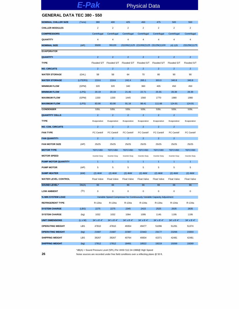
GENERAL DATA TEC 380 - 550
NOMINAL CHILLER SIZE (Tons) 380 400 425 450 475 500 550
CHILLER MODULES 2 2 2 2 2 2 2
COMPRESSORS Centrifugal Centrifugal Centrifugal Centrifugal Centrifugal Centrifugal Centrifugal
QUANTITY 4 4 4 4 4 4 4
NOMINAL SIZE (HP) 90/90 90/100 (3)100/(1)125 (2)100/(2)125 (3)125/(1)100 (4) 125 (3)125/(1)175
EVAPORATOR
QUANTITY 2 2 2 2 2 2 2
TYPE Flooded S/T Flooded S/T Flooded S/T Flooded S/T Flooded S/T Flooded S/T Flooded S/T
NO. CIRCUITS 2 2 2 2 2 2 2
WATER STORAGE (GAL) 58 58 64 70 80 90 90
WATER STORAGE (LITERS) 219.6 219.6 242.4 265.1 303.0 340.8 340.8
MINIMUM FLOW (GPM) 320 320 340 360 405 450 450
MINIMUM FLOW (LPS) 20.19 20.19 21.45 22.71 25.55 28.39 28.39
MAXIMUM FLOW (GPM) 1330 1330 1445 1560 1770 1980 1980
MAXIMUM FLOW (LPS) 83.90 83.90 91.16 98.41 111.66 124.91 124.91
CONDENSER 535L 535L 535L 535L 535L 535L 535L
QUANTITY CELLS 2 2 2 2 2 2
TYPE Evaporative Evaporative Evaporative Evaporative Evaporative Evaporative Evaporative
NO. COIL CIRCUITS 2 2 2 2 2 2
FAN TYPE FC Centrif FC Centrif FC Centrif FC Centrif FC Centrif FC Centrif FC Centrif
FAN QUANTITY 2 2 2 2 2 2
FAN MOTOR SIZE (HP) 25/25 25/25 25/25 25/25 25/25 25/25 25/25
MOTOR TYPE TEFC/VBD TEFC/VBD TEFC/VBD TEFC/VBD TEFC/VBD TEFC/VBD TEFC/VBD
MOTOR SPEED Inverter Duty Inverter Duty Inverter Duty Inverter Duty Inverter Duty Inverter Duty Inverter Duty
PUMP MOTOR QUANTITY 1 1 1 1 1 1 1
PUMP MOTOR (HP) 5 5 5 5 5 5 5
SUMP HEATER (kW) (2) 4kW (2) 4kW (2) 4kW (2) 4kW (2) 4kW (2) 4kW (2) 4kW
WATER LEVEL CONTROL Float Valve Float Valve Float Valve Float Valve Float Valve Float Valve Float Valve
SOUND LEVEL* Db(A) 66 66 66 66 66 66 66
LOW AMBIENT (oF) 0 0 0 0 0 0 0
% MIN SYSTEM LOAD Variable Speed Compressor for Continuously Variable Capacity Adjustment
REFRIGERENT TYPE R-134a R-134a R-134a R-134a R-134a R-134a R-134a
SYSTEM CHARGE (LBS) 2275 2275 2345 2415 2525 2635 2635
SYSTEM CHARGE (kg) 1032 1032 1064 1095 1145 1195 1195
UNIT DIMENSIONS (L x W) 34' x 8'-4" 34' x 8'-4" 34' x 8'-4" 34' x 8'-4" 34' x 8'-4" 34' x 8'-4" 34' x 8'-4"
OPERATING WEIGHT LBS 47810 47810 49354 49477 51096 51291 51374
OPERATING WEIGHT (kg) 21687 21687 22387 22443 23177 23266 23303
SHIPPING WEIGHT LBS 39267 39267 40764 40834 42371 42481 42481
SHIPPING WEIGHT (kg) 17812 17812 18491 18522 19219 19269 19269
*dB(A) = Sound Pressure Level (SPL) Per ANSI S12.34-1988@ High Speed
26 Noise sources are recorded under free field conditions over a reflecting plane @ 50 ft.

27
UL Labeled
Centrifugal Compressor Chiller Electrical Data
MODEL COMPRESSOR FAN MOTOR PUMP MOTOR 460-3-60
Qty HP HP Qty HP Qty HP RLA MCA MOPSINGLE CHILLER TEC 60-90 2 30 30 1 5 1 1 61 66.7 90 TEC 70-112 2 35 35 1 7.5 1 1.5 74 80.5 100 TEC 80-135 2 40 40 1 10 1 1.5 86 93.6 125 TEC 90-144S 2 45 45 1 7.5 1 1.5 90 98.3 125 TEC 100-155L 2 50 50 1 10 1 1.5 100 109.2 150 TEC 110-170L 2 60 50 1 15 1 1.5 114 124.7 150 TEC 120-190LS 2 60 60 1 10 1 2 116 127.3 175 TEC 130- 210L 2 70 60 1 15 1 2 130 142.9 200 TEC 140-212LS 2 70 70 1 10 1 2 135 148.5 200 TEC 150-235L 2 75 75 1 15 1 2 153 168.3 225 TANDEM PACKAGES TEC 160-261LS 4 40/40 40/40 2 10/10 1 3 151 159 200 TEC 170-261LS 4 50/40 40/40 2 10/10 1 3 155 163.5 200 TEC 180-288LS 4 50/40 50/40 2 15/15 1 3 165 173.5 200 TEC 190-310L 4 50/50 50/40 2 10/10 1 3 185 194.4 225 TEC 200-310L 4 50/50 50/50 2 10/10/ 1 3 192 201.4 225 TEC 210-340L 4 60/50 50/50 2 15/15 1 3 214 223.9 250 TEC 220-340L 4 60/50 60/50 2 15/15 1 3 221 231.5 250 TEC 240-380LS 4 60/60 60/60 2 10/10 1 5 219 230.1 250 TEC 260-380LS 4 70/60 70/60 2 10/10 1 5 219 230.1 250 TEC 280-425L 4 70/70 70/70 2 10/10 1 5 256 270.1 300 TEC 300-500L 4 75/75 75/75 2 20/20 1 5 261 275.9 300 TEC 320-500L 4 80/80 80/80 2 20/20 1 5 310 325 350 TEC 340-535L 4 90/80 90/80 2 25/25 1 5 340 365.3 400 TEC360-535L 4 90/90 90/90 2 25/25 1 5 376 395.1 450 TEC 380-535L 4 100/90 100/90 2 25/25 1 5 364 382.3 450 TEC 400-535L 4 100/100 100/100 2 25/25 1 5 402 422.3 500 TEC 425-535L 4 110/100 110/100 2 25/25 1 5 426 477.8 500 TEC 450-535L 4 120/110 110/110 2 25/25 1 5 449 472 600 TEC 475-535L 4 120/120 120/110 2 25/25 1 5 472 497.2 600 TEC 500-535L 4 130/120 130/120 2 25/25 1 5 490 515.8 600 TEC 550-535L 4 140/140 140/130 2 25/25 1 5 546 578.3 700
Electrical ratings are based upon Nominal Chiller Ratings (44o F LWT, 10o F ∆T, 78o F WB)
Single point Power Distribution Center furnished by E-Pak. RLA = System Running Load Amps, includes Compressors, Condenser Fans and Pump motor MCA = Minimum Circuit Ampacity, includes Compressors, Condenser Fans and Pump motor MOP = Maximum Overcurrent Protection, includes Compressors, Condenser Fans and Pump motor
208/230 volt systems are shipped with Wye Delta Start as standard

28
REVOLUTIONARY REFRIGERATION
TEC 60-90L TEC 70-112L
TEC 80- 135L TEC 90-144S
TEC 100-155L TEC 110-170LOR
TE
CHNOLOGY Single Chiller Module General Arrangement Footprint TEC 120-190LS TEC 130-210L TEC 140-212LS TEC 150-235L
TECREUT
GERATION
E-PAK

29
REVOLUTIONARY REFRIGERATION COMPRESSOR MaTECHNOLOGY
TTECEC Tandem Chiller Modules
General Arrangement
Footprint55-90T
55-90L CTTTTTT LUTIY REFESSOR TECHNOLOGY
OLUTIONARY REFRI HNOLOGY
E-PAK
TEC 160-261LS
To
TEC 220-340L
TEC 240-380LS To TEC 550-535L

GENERAL The chiller is an evaporative cooled chillercompletely packaged on a self-supportingsteel frame with all refrigerant piping andinterconnecting power and control wiringinstalled and tested by the manufacturerprior to shipment.
The chiller is suitable for outdoor installa-tion with all chiller components enclosedin a protective aluminum weather housingand all unprotected system componentsare suitable for outdoor operation.
The chiller has a minimum system energyefficiency ratio (EER) including compres-sors, condenser fan(s), condenser pumpand control power and a system energyconsumption rate as specified in the chillerequipment schedule.
The chiller performance is rated in accordance with ARI standard 590.
COMPRESSOR MOTORThe chiller is equipped with multiple semihermetic, gear driven helical rotaryscrew compressors with each compressorinstalled in an independent refrigerant circuit.
Each compressor has liquid and dischargeservice stop valve (suction stop valveoptional); internal and external oil filters;internal pressure relief; low oil flow pro-tection; double mesh suction inlet strain-ers; electrically actuated step unloaders;rubber-in-shear isolation mountings andshall operate with HFC-134a refrigerant.
EVAPORATOR (R-134A)FLOODED:Each evaporator is dual circuited shell & tube design with seamless internallyenhanced copper tubes roller expandedinto the tubesheets. Designed, tested andstamped in accordance with ASME pres-sure vessel code for refrigerant side work-ing pressure of 220 psig and a maximumfluid side pressure of 320 psig.
The water side heads are removable foralternating left hand or right hand waterconnection and tubes are mechanicallycleanable. Each evaporator contains temperature sensors to control leavingfluid temperature, low refrigerant temper-ature freeze protection, and is equippedwith vent and drain connections and insulated with 3/4-inch closed cell insulation with a .28 K valve.
Low ambient applications (optional) areequipped with heat tracing system to protect against evaporator freeze up.
REFRIGERANT CIRCUITSThe chiller has multiple independentrefrigeration circuits. Each circuit includesan oil separator which is tested andstamped in accordance with ASME codefor a working pressure of 320 psig, dis-charge service valves, replaceable corefilter driers, combination moisture indica-tor sight glass, electronic expansion valve,charging valves and insulated suction linesand low side relief valves are provided for each circuit (300 psi). Each refrigerantcircuit is pressure tested, evacuated and shipped with a complete charge of compressor oil and a holding charge at 30 psi of refrigerant HFC-134a.
CONDENSERThe chiller unit is equipped with a forceddraft multi-circuit evaporative condenserwhich is selected to provide the heat ofrejection capacity required by the chillerat the specified condition.
PAN & CASINGThe pan and casing is constructed of G-235 hot dip galvanized steel.
The pan/fan section includes fan(s) withmotors and drives mounted and alignedat the factory. The motors and weathersafety shields are removed for shipping to be reinstalled in the field.
Standard pan accessories include circularaccess doors, stainless steel strainers,waste water bleed line with adjustablevalve and brass make-up valve with anunsinkable foam filled plastic float.
E-PAK
30
CAPACITIES FROM 80 TONS TO 535 TONSFLOODED EVAPORATOR
CLEANABLE WATER SIDE COOLER TUBES
LOW MCA ALLOWS MORE CAPACITY ON SMALLER ELECTRICAL SERVICE
EVAPORATIVE COOLED FLOODED EVAPORATORSCREW COMPRESSOR PACKAGED CHILLERS

CENTRIFUGAL FANSThe fans are forward curved centrifugaltype of hot dip galvanized construction.The fans are factory installed to the pan/fan section, statically and dynamicallybalanced. The fans are mounted on eithera solid or hollow steel shaft with forgedjournal bearings. The fan shaft is support-ed by heavy duty, self-aligning bearingswith cast-iron housings and lubrication fittings for maintenance.
The fan drive(s) are V-Belt type with taperlock sheaves designed for 150% of themotor nameplate horsepower. The drive(s)are mounted and aligned at the factory.
FAN MOTORTotally enclosed fan cooled motor(s) with a 1.15 service factor (inverter duty typemotor with a 1.25 service factor whenused in conjuction with a variable fre-quency drive) is furnished suitable for outdoor service. Motor(s) are mounted on an adjustable base. (See Fan Motor,page 20.)
HEAT TRANSFER COILThe coil(s) are constructed entirely ofprime surface steel, encased in steelframework with the entire assembly hot-dip galvanized after fabrication. Coil(s)are designed with sloping tubes for freedrainage of liquid refrigerant and testedto 350 psig air pressure under water. Each coil circuit is sized for the heat of rejection capacity of each individualrefrigerant circuit. The coil features ellipti-cal tube design which permits greaterwater loading, lower air flow resistanceand higher heat transfer efficiency.
SUBCOOLING COILThe subcooling coil, when required, is also prime surface steel, encased in a steelframework with the entire assembly hot dipgalvanized after fabrication. The refrigerantInlet line to the subcooler is trapped tomaintain a liquid seal to the subcooler,which trap is also furnished with a liquidindicator sight glass. These coils aredesigned with sloping tubes for freedrainage of refrigerant and tested to 350
psig air pressure under water. Each coil circuit is sized to provide the necessary sub-cooling required at each expansion valve.
WATER DISTRIBUTION SYSTEMThe system provides a water flow rate of not less than 6 GPM over each squarefoot of unit face area to ensure properflooding of the coil. The spray header isconstructed of schedule 40, PVC pipe forcorrosion resistance. All spray branchesare removable and include a threadedend plug for cleaning. The water is distributed over the entire coil surface by precision molded ABS spray nozzles(1" x 1/2" orifice) with internal anti-sludge rings to eliminate clogging.Nozzles are threaded into spray headerto provide easy removal for maintenance.
WATER RECIRCULATION PUMPThe pump is a close-coupled, bronze fit-ted, centrifugal type with mechanical seal,installed vertically at the factory to allowfree drainage on shut down. The totallyenclosed motor is furnished suitable foroutdoor service.
ELIMINATORSThe eliminators are constructed entirely of PVC that has been specially treated toresist ultra-violet light. Assembled in easilyhandled sections, the eliminator bladesare spaced on 1-inch centers and incor-porate three changes in air direction toassure removal of entrained moisture from the discharge air stream. They havea hooked leaving edge to direct the dis-charge air away from the fans to mini-mize recirculation.
FINISHAll pan and casing materials are con-structed of G-235 heavy gauge mill hot-dip galvanized steel for maximum protec-tion against corrosion. During fabrication,all panel edges are coated with a 95% pure zinc-rich compound.
CHILLER CONTROL SYSTEMThe chiller is equipped with a fully inte-grated microprocessor control systemwhich includes all controls and sensorsfactory mounted and tested prior to shipment. The standard microprocessor|is equipped with a 2-Line 14 characterper line diagnostic display with data entry control key pad. (A 16 line, 40 character per line expanded display is an available option).
The microprocessor control system pro-vides all control functions including startup and shut down, anti-recycle logic,automatic lead/lag compressor starting/leaving chilled fluid temperature controlwith return fluid sensing and evaporatorfreeze protection. The microprocessor iscapable of limiting the chilled fluid pulldown rate at start up to an adjustablerange of 0.2°F to 2.0°F per minute to prevent demand spikes at start up andprovide seven day time scheduling of condenser pumps, chilled water pumpsand chillers.
DIAGNOSTICSThe microprocessor display module iscapable of displaying set points, time, system status including temperatures, pressures, percent loading and dailyalarm or alert conditions.
The control module is capable of displaying the output of a run test to verify operation of every switch, sensor,potentiometer and compressor beforechiller is started.
SAFETIESThe control systems provides the chillerunit with protection against the following:
Loss of Refrigerant ChargeGround CurrentReverse RotationThermal OverloadLow Chilled Fluid TemperatureHigh PressureLow Oil PressureElectrical OverloadVoltage ImbalanceLoss of Phase
SCREW COMPRESSOR CHILLERS — FLOODED EVAPORATOR
31

E-PAK
WEATHER HOUSINGThe chiller weather housing is constructedof 0.080 thick mill finished aluminum and is equipped with piano hinged accessdoors and lift-off panels to provide maxi-mum accessability to the chiller compo-nents for service and maintenance.
The weather housing roof is sectionallyconstructed for removal for crane accessto the compressors. The roof is sloped forwater and snow runoff and capable of supporting a 35 lb./sq. foot snowload. All access doors are double-wallconstruction.
OPERATING CHARACTERISTICSThe chiller is capable of start up with95°F entering fluid temperature to thecooler. The standard unit power supply is 460V-3 phase - 60 Hz with across theline compressor starters (Wye-Delta StartOptional)
208/230V - 3 Phase - 60 Hz units areprovided with Wye-Delta starters as standard.
The chiller module(s) and all system elec-trical components are rated in accordancewith Underwriters Laboratories (UL), U.S.A.
OPTIONSSee Appendix A for additional optionspecifications.
32
MODEL CAPACITYCOMPRESSORSYSTEM SYSTEM SYSTEM TOTAL HEATNUMBER TONS KW KW KW/TON EER OF REJECTION
SINGLE PACKAGESECC-80-126LS 80.3 50.2 58.3 0.73 16.53 1,135.00
ECC-90-135L 88.4 56.2 66.4 0.75 15.98 1,252.70
ECC-90-144LS 88.6 56 64.1 0.72 16.59 1,254.40
ECC-100-155L 99.9 62.7 72.9 0.73 16.44 1,412.90
ECC-110-170L 111 70 84.4 0.76 15.78 1,571.10
ECC-110-190LS 111.8 69.3 80 0.72 16.77 1,578.30
ECC-120-190LS 120.5 74.2 84.8 0.7 17.05 1,699.40
ECC-130-210L 130.4 80.8 95.7 0.73 16.35 1,840.70
ECC-145-235L 144.5 91.7 106.6 0.74 16.27 2,047.20
ECC-155-235L 154.5 98.6 113.5 0.73 16.33 2,190.70
ECC-161-250L 159.1 100.7 119.6 0.75 15.96 2,253.10
ECC-171-250L 168 110 128.9 0.77 15.64 2,391.70
ECC-181-250L 178.7 120.4 139.3 0.78 15.39 2,555.60
TANDEM PACKAGESECC-160-251LS 160.6 100.4 116.5 0.73 16.54 2,270.10
ECC-170-270L 168.7 106.4 126.7 0.75 15.98 2,387.80
ECC-180-270L 176.8 112.4 132.7 0.75 15.99 2,505.40
ECC-185-288LS 188.3 118.9 135 0.72 16.74 2,665.60
ECC-200-310L 199.8 125.4 145.7 0.73 16.46 2,825.80
ECC-210-340L 211 132 160.8 0.76 15.75 2,982.80
ECC-220-340L 222 140 168.8 0.76 15.78 3,142.10
ECC-235-380LS 232 144 166.1 0.72 16.76 3,275.80
ECC-245-380LS 241 148.4 170.5 0.71 16.96 3,398.80
ECC-255-420L 251 153.5 184 0.73 16.37 3,536.20
ECC-265-425LS 261 161.6 183.7 0.7 17.05 3,683.90
ECC-275-425LS 274.5 173 195.1 0.71 16.88 3,884.80
ECC-290-470L 289 183.4 213.9 0.74 16.21 4,094.30
ECC-300-470L 299 190.3 220.8 0.74 16.25 4,237.90
ECC-310-470L 308 198.2 228.7 0.74 16.16 4,372.90
ECC-315-500L 313.6 199.3 238 0.76 15.81 4,443.80
ECC-320-500L 318.2 201.4 240.1 0.75 15.9 4,506.20
ECC-330-535L 327.3 207.7 246.4 0.75 15.94 4,636.90
ECC-340-535L 336.4 214 260.9 0.78 15.47 4,767.60
ECC-350-535L 348 223 269.9 0.78 15.47 4,937.50
ECC-360-535L 357.8 239 285.9 0.8 15.02 5,109.80
ECC-400-535L 393.8 257 303.9 0.77 15.55 5,603.20
ECC-430-535L 429 283.8 330.7 0.77 15.57 6,117.20
ECC-460-535L 463.1 313 359.9 0.78 15.44 6,626.60
ECC-490-535L 496.6 349.1 396 0.8 15.05 7,139.40
ECC-500-535L 504.2 356.9 403.8 0.8 14.98 7,269.30
ECC-515-535L 511.2 370.6 417.5 0.82 14.7 7,400.00
ECC-520-535L 520.8 379.8 426.7 0.82 14.6 7,546.40
ECC-530-535L 529.6 396.6 443.5 0.84 14.33 7,709.60
*Nominal ratings based on 44°F leaving water temperature, 10°F ∆T, 78°F wet bulb temperature.
NOMINAL RATINGS FLOODED EVAPORATOR
E-Pak Control Panel
SCREW COMPRESSOR CHILLERS — FLOODED EVAPORATOR
33
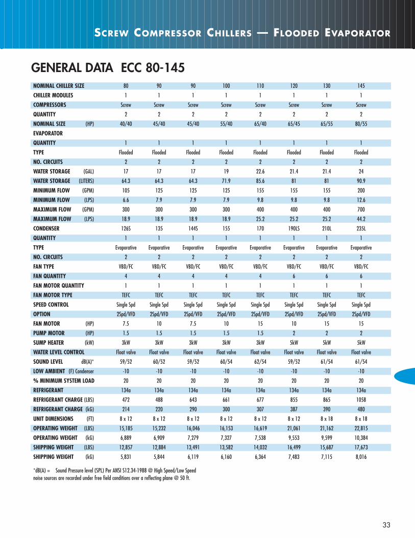
NOMINAL CHILLER SIZE 80 90 90 100 110 120 130 145
CHILLER MODULES 1 1 1 1 1 1 1 1
COMPRESSORS Screw Screw Screw Screw Screw Screw Screw Screw
QUANTITY 2 2 2 2 2 2 2 2
NOMINAL SIZE (HP) 40/40 45/40 45/40 55/40 65/40 65/45 65/55 80/55
EVAPORATOR
QUANTITY 1 1 1 1 1 1 1 1
TYPE Flooded Flooded Flooded Flooded Flooded Flooded Flooded Flooded
NO. CIRCUITS 2 2 2 2 2 2 2 2
WATER STORAGE (GAL) 17 17 17 19 22.6 21.4 21.4 24
WATER STORAGE (LITERS) 64.3 64.3 64.3 71.9 85.6 81 81 90.9
MINIMUM FLOW (GPM) 105 125 125 125 155 155 155 200
MINIMUM FLOW (LPS) 6.6 7.9 7.9 7.9 9.8 9.8 9.8 12.6
MAXIMUM FLOW (GPM) 300 300 300 300 400 400 400 700
MAXIMUM FLOW (LPS) 18.9 18.9 18.9 18.9 25.2 25.2 25.2 44.2
CONDENSER 126S 135 144S 155 170 190LS 210L 235L
QUANTITY 1 1 1 1 1 1 1 1
TYPE Evaporative Evaporative Evaporative Evaporative Evaporative Evaporative Evaporative Evaporative
NO. CIRCUITS 2 2 2 2 2 2 2 2
FAN TYPE VBD/FC VBD/FC VBD/FC VBD/FC VBD/FC VBD/FC VBD/FC VBD/FC
FAN QUANTITY 4 4 4 4 4 6 6 6
FAN MOTOR QUANTITY 1 1 1 1 1 1 1 1
FAN MOTOR TYPE TEFC TEFC TEFC TEFC TEFC TEFC TEFC TEFC
SPEED CONTROL Single Spd Single Spd Single Spd Single Spd Single Spd Single Spd Single Spd Single Spd
OPTION 2Spd/VFD 2Spd/VFD 2Spd/VFD 2Spd/VFD 2Spd/VFD 2Spd/VFD 2Spd/VFD 2Spd/VFD
FAN MOTOR (HP) 7.5 10 7.5 10 15 10 15 15
PUMP MOTOR (HP) 1.5 1.5 1.5 1.5 1.5 2 2 2
SUMP HEATER (kW) 3kW 3kW 3kW 3kW 3kW 5kW 5kW 5kW
WATER LEVEL CONTROL Float valve Float valve Float valve Float valve Float valve Float valve Float valve Float valve
SOUND LEVEL dB(A)* 59/52 60/52 59/52 60/54 62/54 59/52 61/54 61/54
LOW AMBIENT (F) Condenser -10 -10 -10 -10 -10 -10 -10 -10
% MINIMUM SYSTEM LOAD 20 20 20 20 20 20 20 20
REFRIGERANT 134a 134a 134a 134a 134a 134a 134a 134a
REFRIGERANT CHARGE (LBS) 472 488 643 661 677 855 865 1058
REFRIGERANT CHARGE (kG) 214 220 290 300 307 387 390 480
UNIT DIMENSIONS (FT) 8 x 12 8 x 12 8 x 12 8 x 12 8 x 12 8 x 12 8 x 18 8 x 18
OPERATING WEIGHT (LBS) 15,185 15,232 16,046 16,153 16,619 21,061 21,162 22,815
OPERATING WEIGHT (kG) 6,889 6,909 7,279 7,327 7,538 9,553 9,599 10,384
SHIPPING WEIGHT (LBS) 12,857 12,884 13,491 13,582 14,032 16,499 15,687 17,673
SHIPPING WEIGHT (kG) 5,831 5,844 6,119 6,160 6,364 7,483 7,115 8,016
*dB(A) = Sound Pressure level (SPL) Per ANSI S12.34-1988 @ High Speed/Low Speednoise sources are recorded under free field conditions over a reflecting plane @ 50 ft.
GENERAL DATA ECC 80-145

E-PAK
34
NOMINAL CHILLER SIZE 155 161 171 181 160 170 180 185 200
CHILLER MODULES 1 1 1 1 2 2 2 2 2
COMPRESSORS Screw Screw Screw Screw Screw Screw Screw Screw Screw
QUANTITY 2 2 2 2 4 4 4 4 4
NOMINAL SIZE (HP) 80/65 80/55 65/80 80/80 40/40-40/40 45/40-40/40 45/40-45/40 55/40-45/40 55/40-55/40
EVAPORATOR
QUANTITY 1 1 1 1 2 2 2 2 2
TYPE Flooded Flooded Flooded Flooded Flooded Flooded Flooded Flooded Flooded
NO. CIRCUITS 2 2 2 2 4 4 4 4 4
WATER STORAGE (GAL) 24 28.5 28.5 33.4 17/17 17/17 17/17 17/19 19/19
WATER STORAGE (LITERS) 90.9 107.9 107.9 126.4 64.3/64.3 64.3/64.3 64.3/64.3 64.3/71.9 71.9/71.9
MINIMUM FLOW (GPM) 210 240 240 270 105/105 105/125 125/125 125/125 125/125
MINIMUM FLOW (LPS) 13.2 15.1 15.1 17 6.6/6.6 6.6/7.9 7.9/7.9 7.9/7.9 7.9/7.9
MAXIMUM FLOW (GPM) 700 700 700 700 300/300 300/300 300/300 300/300 300/300
MAXIMUM FLOW (LPS) 44.2 44.2 44.2 44.2 18.9/18.9 18.9/18.9 18.9/18.9 18.9/18.9 18.9/18.9
CONDENSER 235L 250L 250L 250L 251LS 270L 270L 288LS 310L
QUANTITY 1 1 1 1 1 1 1 1 1
TYPE evaporative evaporative evaporative evaporative evaporative evaporative evaporative evaporative evaporative
NO. CIRCUITS 2 2 2 2 4 4 4 4 4
FAN TYPE VBD/FC VBD/FC VBD/FC VBD/FC VBD/FC VBD/FC VBD/FC VBD/FC VBD/FC
FAN QUANTITY 6 6 6 6 8 8 8 8 8
FAN MOTOR QUANTITY 1 1 1 1 2 2 2 2 2
FAN MOTOR TYPE TEFC TEFC TEFC TEFC TEFC TEFC TEFC TEFC TEFC
FAN MOTOR SPEED STANDARD Single Spd Single Spd Single Spd Single Spd Single Spd Single Spd Single Spd Single Spd Single Spd
OPTION 2Spd/VFD 2Spd/VFD 2Spd/VFD 2Spd/VFD 2Spd/VFD 2Spd/VFD 2Spd/VFD 2Spd/VFD 2Spd/VFD
FAN MOTOR HP 15 20 20 20 (2)7.5 (2)10 (2)10 (2)7.5 (2)10
PUMP MOTOR HP 2 2 2 2 3 3 3 3 3
SUMP HEATER kW 5kW 5kW 5kW 5kW 5kW 5kW 5kW 5kW 5kW
WATER LEVEL CONTROL Float valve Float valve Float valve Float valve Float valve Float valve Float valve Float valve Float valve
SOUND LEVEL dB(A)* 61/54 61/54 61/54 61/54 62/55 63/56 63/56 62/55 64/57
LOW ABMIENT (F) Condenser -10 -10 -10 -10 -10 -10 -10 -10 -10
% MINIMUM SYSTEM LOAD 20 20 20 20 10 10 10 10 10
REFRIGERANT 134a 134a 134a 134a 134a 134a 134a 134a 134a
REFRIGERANT CHARGE (LBS) 1054 1085 809 804 1142 1158 1158 1448 1448
REFRIGERANT CHARGE (kG) 478 492 366 364 518 525 525 656 656
UNIT DIMENSIONS (FT) 8 x 18 8 x 18 8 x 18 8 x 18 8 x 22 8 x 22 8 x22 8 x 22 8 x 22
OPERATING WEIGHT (LBS) 22,686 22,724 22,887 23,056 29,622 29,681 29,708 33,060 34,103
OPERATING WEIGHT (kG) 10,290 10,307 10,381 10,458 13,436 13,463 13,475 14,996 15,469
SHIPPING WEIGHT (LBS) 17,677 17,560 12,998 18,182 22,208 27,235 22,762 25,661 26,501
SHIPPING WEIGHT (kG) 8,018 7,965 8,163 8,242 10,073 10,085 10,324 11,639 12,020
*dB(A)= Sound Pressure level (SPL) Per ANSI S12.34-1988 @ High Speed/Low Speednoise sources are recorded under free field conditions over a reflecting plane @ 50 ft.
GENERAL DATA ECC 155-200

SCREW COMPRESSOR CHILLERS — FLOODED EVAPORATOR
35
NOMINAL CHILLER SIZE 210 220 235 245 255 265 275 290 300
CHILLER MODULES 2 2 2 2 2 2 2 2 2
COMPRESSORS Screw Screw Screw Screw Screw Screw Screw Screw Screw
QUANTITY 4 4 4 4 4 4 4 4 4
NOMINAL SIZE (HP) 65/40-55/40 65/40-65/40 65/40-65/45 65/45-65/45 65/45-65/55 65/55-65/55 65/55-80/55 80/55-80/55 80/55-80/65
EVAPORATOR
QUANTITY 2 2 2 2 2 2 2 2 2
TYPE Flooded Flooded Flooded Flooded Flooded Flooded Flooded Flooded Flooded
NO. CIRCUITS 4 4 4 4 4 4 4 4 4
WATER STORAGE (GAL) 19/22.6 22.6/22.6 22.6/21.4 21.4/21.4 21.4/21.4 21.4/21.4 21.4/24.0 24.0/24.0 24.0/24.0
WATER STORAGE (LITERS) 71.9/85.6 85.6/85.6 85.6/81.0 81.0/81.0 81.0/81.0 81.0/81.0 81.0/90.9 90.9/90.9 90.9/90.9
MINIMUM FLOW GPM) 125/155 155/155 155/155 155/155 155/155 155/155 155/200 200/200 200/210
MINIMUM FLOW (LPS) 7.9/9.8 9.8/9.8 9.8/9.8 9.8/9.8 9.8/9.8 9.8/9.8 9.8/12.6 12.6/12.6 12.6/13.2
MAXIMUM FLOW (GPM) 300/400 400/400 400/400 400/400 400/400 400/500 500/600 600/600 600/600
MAXIMUM FLOW (LPS) 18.9/25.2 25.2/25.2 25.2/25.2 25.2/25.2 25.2/25.2 25.2/25.2 25.2/44.2 44.2/44.2 44.2/44.2
CONDENSER 340L 340L 380LS 380LS 420L 425LS 425LS 470L 470L
QUANTITY 1 1 1 1 1 1 1 1 1
TYPE evaporative evaporative evaporative evaporative evaporative evaporative evaporative evaporative evaporative
NO. CIRCUITS 4 4 4 4 4 4 4 4 4
FAN TYPE VBD/FC VBD/FC VBD/FC VBD/FC VBD/FC VBD/FC VBD/FC VBD/FC VBD/FC
FAN QUANTITY 8 8 12 12 12 12 12 12 12
FAN MOTOR QUANTITY 2 2 2 2 2 2 2 2 2
FAN MOTOR TYPE TEFC TEFC TEFC TEFC TEFC TEFC TEFC TEFC TEFC
FAN MOTOR SPEED STANDARD Single Spd Single Spd Single Spd Single Spd Single Spd Single Spd Single Spd Single Spd Single Spd
OPTION 2Spd/VFD 2Spd/VFD 2Spd/VFD 2Spd/VFD 2Spd/VFD 2Spd/VFD 2Spd/VFD 2Spd/VFD 2Spd/VFD
FAN MOTOR HP 15/15 10/10 10/10 10/10 10/10 10/10 10/10 15/15 15/15
PUMP MOTOR HP 3 5 5 5 5 5 5 5 5
SUMP HEATER kW 5kW 5kW (2) 4kW (2) 4kW (2) 4kW (2) 4kW (2) 4kW (2) 4kW (2) 4kW
WATER LEVEL CONTROL Float valve Float valve Float valve Float valve Float valve Float valve Float valve Float valve Float valve
SOUND LEVEL dB(A)* 64/57 64/57 61/54 61/54 62/55 61/54 61/54 63/56 63/56
LOW ABMIENT (F) Condenser -10 -10 -10 -10 -10 -10 -10 -10 -10
% MINIMUM SYSTEM LOAD 10 10 10 10 10 10 10 10 10
REFRIGERANT 134a 134a 134a 134a 134a 134a 134a 134a 134a
REFRIGERANT CHARGE (LBS) 1464 1464 1169 1164 1171 1432 1444 1444 1444
REFRIGERANT CHARGE (kG) 664 664 530 528 531 650 655 655 655
UNIT DIMENSIONS (FT) 8 x22 8 x22 8 x31 8 x35 8 x35 8 x35 8 x35 8 x35 8 x35
OPERATING WEIGHT (LBS) 33,649 33,965 40,605 40,616 40,775 43,742 43,845 42,978 40,617
OPERATING WEIGHT kG) 15,263 15,406 18,418 18,423 18,495 14,886 19,888 19,494 18,423
SHIPPING WEIGHT (LBS) 25,869 26,007 30,922 30,938 30,829 32,818 32,909 33,116 33,146
SHIPPING WEIGHT (kG) 11,731 11,796 14,026 14,033 13,984 14,886 14,925 15,021 15,035
*dB(A) = Sound Pressure level (SPL) Per ANSI S12.34-1988 @ High Speed/Low SpeedNoise sources are recorded under free field conditions over a reflecting plane @ 50 ft.
GENERAL DATA ECC 210-300

36
E-PAK
NOMINAL CHILLER SIZE 310 315 320 330 340 350 360 400 430
CHILLER MODULES 2 2 2 2 2 2 2 2 2
COMPRESSORS Screw Screw Screw Screw Screw Screw Screw Screw Screw
QUANTITY 4 4 4 4 4 4 4 5 6
NOMINAL SIZE (HP) 80/65-80/65 80/65-80/65 (2) 80/55 80/55-80/65 (2) 80/65 80/65-80/80 (2) 80/80 80/80-65/40/80 (2) 65/40/80
EVAPORATOR
QUANTITY 2 2 2 2 2 2 2 2 2
TYPE Flooded Flooded Flooded Flooded Flooded Flooded Flooded Flooded Flooded
NO. CIRCUITS 4 4 4 4 4 4 4 4 4
WATER STORAGE (GAL) 24.0/24.0 24.0/28.5 28.5/28.5 28.5/28.5 28.5/28.5 28.5/33.4 33.4/33.4 33.4/43.1 43.1/43.1
WATER STORAGE (LITERS) 90.9/90.9 90.9/107.9 107.9/107.9 107.9/107.9 107.9/107.9 107.9/126.4 126.4/126.4 126.4/163.2 163.2/163.2
MINIMUM FLOW (GPM) 210/210 210/240 240/240 240/240 240/240 240/270 270/270 270/324 324/324
MINIMUM FLOW (LPS) 13.2/13.2 13.2/15.1 15.1/15.1 15.1/15.1 15.1/15.1 15.1/17 17/17 17/20.4 20.4/20.4
MAXIMUM FLOW (GPM) 600/600 600/700 700/700 700/700 700/700 700/700 700/700 700/800 800/800
MAXIMUM FLOW (LPS) 44.2/44.2 44.2/44.2 44.2/44.2 44.2/44.2 44.2/44.2 44.2/44.2 44.2/44.2 44.2/50.5 50.5/50.5
CONDENSER 470L 500L 500L 535L 535L 535L 535L 535L 535L
QUANTITY 1 1 1 1 1 1 1 1 1
TYPE Evaporative Evaporative Evaporative Evaporative Evaporative Evaporative Evaporative Evaporative Evaporative
NO. CIRCUITS 4 4 4 4 4 4 4 4 4
FAN TYPE VBD/FC VBD/FC VBD/FC VBD/FC VBD/FC VBD/FC VBD/FC VBD/FC VBD/FC
FAN QUANTITY 12 12 12 12 12 12 12 12 12
FAN MOTOR QUANTITY 2 2 2 2 2 2 2 2 2
FAN MOTOR TYPE TEFC TEFC TEFC TEFC TEFC TEFC TEFC TEFC TEFC
FAN MOTOR SPEED STANDARD Single Spd Single Spd Single Spd Single Spd Single Spd Single Spd Single Spd Single Spd Single Spd
OPTION 2Spd/VFD 2Spd/VFD 2Spd/VFD 2Spd/VFD 2Spd/VFD 2Spd/VFD 2Spd/VFD 2Spd/VFD 2Spd/VFD
FAN MOTOR (HP) 15/15 20/20 20/20 25/25 25/25 25/25 25/25 25/25 25/25
PUMP MOTOR (HP) 5 5 5 5 5 5 5 5 5
SUMP HEATER (kW) (2) 4kW (2) 4kW (2) 4kW (2) 4kW (2) 4kW (2) 4kW (2) 4kW (2) 4kW (2) 4kW
WATER LEVEL CONTROL Float valve Float valve Float valve Float valve Float valve Float valve Float valve Float valve Float valve
SOUND LEVEL dB(A)* 63/56 64/50 64/50 66/54 66/54 66/54 66/54 66/54 66/54
LOW AMBIENT (F) Condenser -10 -10 -10 -10 -10 -10 -10 -10 -10
% MINIMUM SYSTEM LOAD 10 10 10 10 10 10 10 10 10
REFRIGERANT 134a 134a 134a 134a 134a 134a 134a 134a 134a
REFRIGERANT CHARGE (LBS) 1439 1470 1470 1721 1721 1716 1716 1801 1801
REFRIGERANT CHARGE (kG) 653 667 667 781 781 777 778 817 817
UNIT DIMENSIONS (FT) 8 x 35 8 x 35 8 x 35 8 x 27 8 x 35 8 x 35 8 x 29 8 x 29 8 x 29
OPERATING WEIGHT (LBS) 44,115 43,333 43,752 46,022 46,022 46,171 46,340 50,975 55,610
OPERATING WEIGHT (kG) 20,010 19,655 19,845 20,875 20,875 20,943 21,019 23,122 25,224
SHIPPING WEIGHT (LBS) 33,176 32,333 32,752 34,500 34,500 34,679 34,848 39,313 43,948
SHIPPING WEIGHT (kG) 15,048 14,666 14,856 15,649 15,649 15,730 15,807 17,832 19,934
*dB(A) = Sound Pressure level (SPL) Per ANSI S12.34-1988 @ High Speed/Low SpeedNoise sources are recorded under free field conditions over a reflecting plane @ 50 ft.
GENERAL DATA ECC 310-430

SCREW COMPRESSOR CHILLERS — FLOODED EVAPORATOR
37
NOMINAL CHILLER SIZE 460 490 500 515 520 530
CHILLER MODULES 2 2 2 2 2 2
COMPRESSORS Screw Screw Screw Screw Screw Screw
QUANTITY 6 6 6 6 6 6
NOMINAL SIZE (HP) 65/40/80-80/55/80 (2) 80/55/80 80/55/80-80/65/80 (2) 80/65/80 80/65/80-80/80/80 (2) 80/80/80
EVAPORATOR
QUANTITY 2 2 2 2 2 2
TYPE Flooded Flooded Flooded Flooded Flooded Flooded
NO. CIRCUITS 4 4 4 4 4 4
WATER STORAGE (GAL) 43.1/47.2 47.2/47.2 47.2/47.2 47.2/47.2 47.2/47.2 47.2/47.2
WATER STORAGE (LITERS) 163.2/178.7 178.7/178.7 178.7/178.8 178.8/178.8 178.8/178.8 178.8/178.8
MINIMUM FLOW (GPM) 324/358 358/358 358/358 358/358 358/358 358/358
MINIMUM FLOW (LPS) 20.4/22.6 22.6/22.6 22.6/22.6 22.6/22.6 22.6/22.6 22.6/22.6
MAXIMUM FLOW (GPM) 800/900 900/900 900/900 900/900 900/900 900/900
MAXIMUM FLOW (LPS) 50.5/56.8 56.8/56.8 56.8/56.8 56.8/56.8 56.8/56.8 56.8/56.8
CONDENSER 535L 535L 535L 535L 535L 535L
QUANTITY 1 1 1 1 1 1
TYPE Evaporative Evaporative Evaporative Evaporative Evaporative Evaporative
NO. CIRCUITS 4 4 4 4 4 4
FAN TYPE VBD/FC VBD/FC VBD/FC VBD/FC VBD/FC VBD/FC
FAN QUANTITY 12 12 12 12 12 12
FAN MOTOR QUANTITY 2 2 2 2 2 2
FAN MOTOR TYPE TEFC TEFC TEFC TEFC TEFC TEFC
FAN MOTOR SPEED STANDARD Single Spd Single Spd Single Spd Single Spd Single Spd Single Spd
OPTION 2Spd/VFD 2Spd/VFD 2Spd/VFD 2Spd/VFD 2Spd/VFD 2Spd/VFD
FAN MOTOR (HP) 25/25 25/25 25/25 25/25 25/25 25/25
PUMP MOTOR (HP) 5 5 5 5 5 5
SUMP HEATER (kW) (2) 4kW (2) 4kW (2) 4kW (2) 4kW (2) 4kW (2) 4kW
WATER LEVEL CONTROL Float valve Float valve Float valve Float valve Float valve Float valve
SOUND LEVEL dB(A)* 66/54 66/54 66/54 6654 66/54 66/54
LOW ABMIENT (F) Condenser -10 -10 -10 -10 -10 -10
% MINIMUM SYSTEM LOAD 10 10 10 10 10 10
REFRIGERANT 134a 134a 134a 134a 134a 134a
REFRIGERANT CHARGE (LBS) 1801 1801 1801 1801 1801 1801
REFRIGERANT CHARGE (kG) 817 817 817 817 817 817
UNIT DIMENSIONS (FT)
OPERATING WEIGHT (LBS) 55,998 56,386 56,409 56,432 56,469 56,506
OPERATING WEIGHT (kG) 25,400 25,576 25,576 25,579 25,610 25,631
SHIPPING WEIGHT (LBS) 44,336 44,724 44,747 44,770 44,807 44,844
SHIPPING WEIGHT (kG) 20,110 20,286 20,209 20,307 20,324 20,341
*dB(A) = Sound Pressure level (SPL) Per ANSI S12.34-1988 @ High Speed/Low SpeedNoise sources are recorded under free field conditions over a reflecting plane @ 50 ft.
GENERAL DATA ECC 460-530
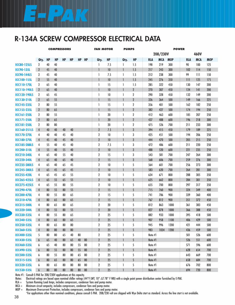
COMPRESSORS FAN MOTOR PUMPS POWER
208/230V 460VQty. HP HP HP HP HP HP Qty. HP Qty. HP RLA MCA MOP RLA MCA MOP
ECC80-125LS 2 40 40 1 7.5 1 1.5 198 219 300 90 100 125
ECC90-135L 2 45 40 1 10 1 1.5 217 243 300 102 114 150
ECC90-144LS 2 45 40 1 7.5 1 1.5 212 238 300 99 111 150
ECC100-155L 2 55 40 1 10 1 1.5 245 276 350 111 125 175
ECC110-170L 2 65 40 1 15 1 1.5 285 322 450 130 147 200
ECC110-190LS 2 65 40 1 10 1 2 270 307 450 124 141 200
ECC120-190LS 2 65 45 1 10 1 2 290 328 450 132 149 200
ECC130-210L 2 65 55 1 15 1 2 326 364 500 149 166 225
ECC145-235L 2 80 55 1 15 1 2 356 401 500 162 182 250
ECC155-235L 2 80 65 1 15 1 2 382 427 500 174 194 250
ECC161-250L 2 80 55 1 20 1 2 412 463 600 185 207 250
ECC171-250L 2 80 65 1 20 1 2 437 488 600 196 218 300
ECC181-250L 2 80 80 1 20 1 2 475 526 700 211 233 300
ECC160-251LS 4 40 40 40 40 2 7.5 1 3 394 415 450 179 189 225
ECC170-270L 4 40 40 45 40 2 10 1 3 425 451 500 194 206 250
ECC180-270L 4 45 40 45 40 2 10 1 3 444 470 500 205 215 250
ECC185-288LS 4 55 40 45 40 2 7.5 1 3 472 486 600 211 220 250
ECC200-310L 4 55 40 55 40 2 10 1 3 488 520 600 221 235 250
ECC210-340L 4 65 40 55 40 2 15 1 3 543 581 700 247 264 300
ECC220-340L 4 65 40 65 40 2 15 1 3 568 606 700 259 276 300
ECC235-380LS 4 65 40 65 45 2 10 1 5 564 601 700 256 273 300
ECC245-380LS 4 65 45 65 45 2 10 1 5 583 620 700 264 281 300
ECC255-420L 4 65 45 65 55 2 10 1 5 634 671 800 288 305 350
ECC265-425LS 4 65 55 65 55 2 10 1 5 625 662 800 284 301 350
ECC275-425LS 4 65 55 80 55 2 10 1 5 655 700 800 297 317 350
ECC290-470L 4 80 55 80 55 2 15 1 5 715 760 900 324 349 400
ECC300-470L 4 80 55 80 65 2 15 1 5 741 786 900 339 360 400
ECC310-470L 4 80 65 80 65 2 15 1 5 767 812 900 351 372 450
ECC315-500L 4 80 65 80 65 2 20 1 5 812 863 1000 361 383 450
ECC320-500L 4 80 55 80 55 2 20 1 5 827 878 1000 366 388 450
ECC330-535L 4 80 55 80 65 2 25 1 5 882 933 1000 395 418 500
ECC340-535L 4 80 65 80 65 2 25 1 5 907 958 1100 406 429 500
ECC350-535L 4 80 65 80 80 2 25 1 5 945 996 1200 421 444 500
ECC360-535L 4 80 80 80 80 2 25 1 5 983 1034 1200 436 459 500
ECC400-535L 5 80 80 65 40 80 2 25 1 5 Note #1 501 526 600
ECC430-535L 6 65 40 80 65 40 80 2 25 1 5 Note #1 526 551 600
ECC460-535L 6 65 40 80 80 55 80 2 25 1 5 Note #1 571 596 600
ECC490-535L 6 80 55 80 80 55 80 2 25 1 5 Note #1 628 654 700
ECC500-535L 6 80 55 80 80 65 80 2 25 1 5 Note #1 643 669 700
ECC515-535L 6 80 65 80 80 65 80 2 25 1 5 Note #1 658 684 700
ECC520-535L 6 80 65 80 80 80 80 2 25 1 5 Note #1 676 702 800
ECC530-535L 6 80 80 80 80 80 80 2 25 1 5 Note #1 694 720 800Note #1: Consult E-PAK for 208/230V applications at this capacity.Notes: Electrical ratings are based upon nominal chiller ratings (44°F LWT, 10° ∆T 78° F WB) with a single point power distribution center furnished by E-PAK.RLA = System Running Load Amps, includes compressors, condenser fans and pump motor.MCA = Minimum circuit ampacity, includes compressors, condenser fans and pump motor.MOP = Maximum Overcurrent Protection, includes compressors, condenser fans and pump motor.
*For applications other than nominal conditions, please consult E-PAK. 208/230 volt are shipped with Wye Delta start as standard. Across the line start is not available.
E-PAK
38
R-134A SCREW COMPRESSOR ELECTRICAL DATA
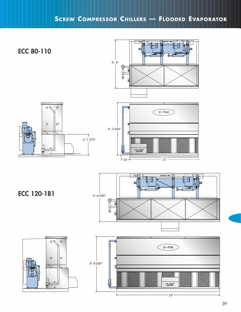
39
SCREW COMPRESSOR CHILLERS — FLOODED EVAPORATOR
ECC 80-110
�
�
�
�
��
ECC 120-181
�
�
8' - 6"
�� 12'
9'- 2.000"
18'
3'- 7.375"
9'- 8.000"
9'- 6.000"
18'
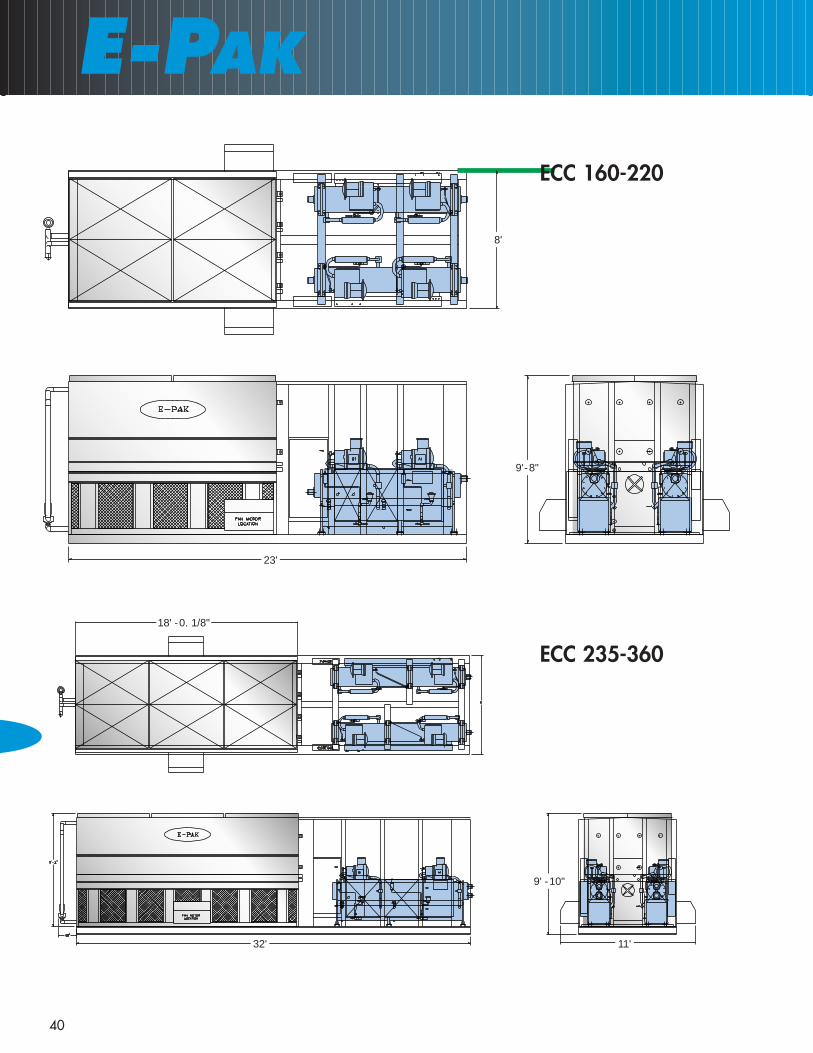
E-PAK
40
ECC 160-220
ECC 235-360
8'
23'
9'- 8"
32' 11'
9' - 10"
18' - 0. 1/8"

41
SCREW COMPRESSOR CHILLERS — FLOODED EVAPORATOR
��
ECC 430-535
34'
8'
9'- 10.2580"9'- 9.9175"
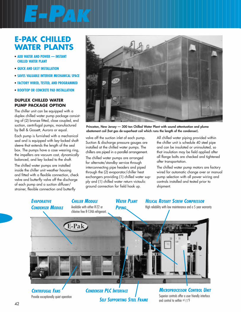
HELICAL ROTARY SCREW COMPRESSORHigh reliability with low maintenance and a 5 year warranty
EVAPORATIVE
CONDENSER MODULE
CHILLER MODULEAvailable with either R-22 or chlorine free R-134A refrigerant.
MICROPROCESSOR CONTROL UNITSuperior controls offer a user friendly interfaceand control to within ±1/2˚FSELF SUPPORTING STEEL FRAME
CENTRIFUGAL FANSProvide exceptionally quiet operation
WATER PLANT
PIPING
CONDENSER PLC INTERFACE
• ADD WATER AND POWER — INSTANT CHILLED WATER PLANT
• QUICK AND EASY INSTALLATION
• SAVES VALUABLE INTERIOR MECHANICAL SPACE
• FACTORY WIRED, TESTED, AND PROGRAMMED
• ROOFTOP OR CONCRETE PAD INSTALLATION
DUPLEX CHILLED WATER PUMP PACKAGE OPTIONThe chiller unit can be equipped with aduplex chilled water pump package consist-ing of (2) bronze fitted, close coupled, endsuction, centrifugal pumps, manufacturedby Bell & Gossett, Aurora or equal.
Each pump is furnished with a mechanicalseal and is equipped with key-locked shaftsleeve that extends the length of the sealbox. The pumps have a case wearing ring,the impellers are vacuum cast, dynamicallybalanced, and key locked to the shaft.
The chilled water pumps are installed inside the chiller unit weather housing and fitted with a flexible connection, checkvalve and butterfly valve off the dischargeof each pump and a suction diffuser/strainer, flexible connection and butterfly
valve off the suction inlet of each pump.Suction & discharge pressure gauges areinstalled at the chilled water pumps. Thechillers are piped in a parallel arrangement.
The chilled water pumps are arranged for alternate/standby service through interconnecting pipe headers and pipedthrough the (2) evaporator/chiller heatexchangers providing (1) chilled water sup-ply and (1) chilled water return victaulicground connection for field hook up.
All chilled water piping provided within the chiller unit is schedule 40 steel pipe and can be insulated or uninsulated, so that insulation may be field applied after all flange bolts are checked and tightened after transportation.
The chilled water pump motors are factorywired for automatic change over or manualpump selection with all power wiring andcontrols installed and tested prior to shipment.
E-PAK
42
E-PAK CHILLEDWATER PLANTS
Princeton, New Jersey — 300 ton Chilled Water Plant with sound attentuation and plume abatement coil (hot gas de-superheat coil which runs the length of the condenser).

43
E-PAK CHILLED WATER PLANTS
DXEvaporator
FloodedEvaporator
94.00
354.00
9' - 3 1/16"
19'
105.00
1' - 6" (TYP)

E-PAK
44
APPENDIX AOPTIONS SPECIFICATIONSEXTENDED 5 YEARCOMPRESSOR WARRANTYThe semi hermetic compressors are furnished with The Compressor Manu-facturer’s Extended 5 Year Warrantywhich extends the standard first year warranty to the 2nd through 5th year of operation.
START-UP AND FIRST YEARWARRANTY LABORThe chiller manufacturer furnishes Factorytrained service technician(s) to check out,charge with refrigerant (refrigerant fur-nished by others), start-up and adjust the chiller system equipment to assureoptimum chiller performance, and instructthe owner in the proper operation andmaintenance of the equipment.
The chiller manufacturer provides quali-fied labor during normal work hours toinstall replacement parts or make repairscovered under the first year standard warranty.
WYE-DELTA COMPRESSORSTARTERSThe chiller module(s) are equipped withWye-Delta compressor motor starterswhich are factory mounted and tested bythe chiller manufacturer.
NON-FUSED DISCONNECTThe chiller module control/starter panel(s)are equipped with a non-fused disconnectswitch mounted in the control/starterpanel door.
BAS COMMUNICATIONINTERFACEThe chiller system is furnished with a Building Automation System Communi-cation interface which provides bi-direction communication to permit remotechilled water set point and demand limit-ing by accepting a 4-20 mA or 2-10VDCanalog signal.
SINGLE POINT POWERDISTRIBUTION SYSTEM OPTIONThe chiller unit is furnished with a SinglePoint Power Distribution Center, 460Volt,3-phase, 60-Hertz. The PDC is furnishedwith a Main circuit breaker/disconnectrated for the total overcurrent protection of the entire system and branch circuitbreaker/disconnects are provided foreach component of the chiller system; one for each chiller module, one for each condenser fan motor, one for thecondenser circulator motor(s), and one forthe accessory power transformer andother options if provided with the unit. All circuit breakers are HACR type suit-able for air conditioning and refrigerationduty and UL rated and the complete unitshall be ETL listed. All electrical systemcomponents are manufactured by Square “D”.
REDUNDANT CONDENSERRECIRCULATION WATER SPRAYPUMPSThe chiller system’s condenser is furnishedwith a redundant spray pump assemblymounted on opposite ends of the evapora-tive condenser and piped from a commonchilled water plant sump to a commonwater distribution spray header.
Each assembly is equipped with a butter-fly valve, check valve and a flow switch toallow automatic change over and repairservices in the event of one pump systemfailure.
CONDENSER INTAKE & DISCHARGE SOUNDATTENUATION OPTIONThe chiller is furnished with intake anddischarge sound traps for field installationby the installation site contractor. Thesound traps are G-235 galvanized steelwith interior walls and baffles acousticallylined with high-density fiberglass. Bothintake and discharge sound traps are sup-ported from the condenser and require noexternal supporting structure. The intakeand discharge sound attenuation plenumsenable the condenser to operate at amaximum overall sound pressure level of 55dB or less at 50 FT when operatingat high speed.
When intake sound traps are furnished,the condenser fan bearings are fitted witha remote lubrication package consisting of (2) grease fittings and (1) oil reservoirlocated at each corner of the condenserendwall to provide proper fan bearinglubrication maintenance without having to enter the intake sound traps.
TAPERED DISCHARGE HOODThe condenser is furnished with a tapereddischarge hood to prevent short-circuitingof the condenser discharge air in space-restricted installations. The hood is con-structed of G-235 galvanized sheet steelpanels and equipped with access doorson both sides to provide access to the drifteliminators. The hood is shipped separatefrom the chiller unit for field installation.
CHILLER ENCLOSURE SOUNDATTENUATIONThe chiller enclosure is constructed of double wall sandwich panels consisting of a mill finished aluminum exterior panel,3/8" acoustical sound control matting ofacoustic foam with a mass loaded vinylbarrier and a galvanized steel interiorpanel. The composite panel has a mass of 5 lb./sq. ft.. All service access doorsand access panels will be similarly con-structed and equipped with stainless steelpiano hinges

45
LOW AMBIENT PACKAGEThe chiller is furnished with Electric heatersat the chiller barrel(s), oil separators andcondenser sump pan as required to pre-vent freezing of the coolant water whenthe chiller is not operating and outdoordry bulb temperatures are below 40°F.All electrical controls are factory wiredand tested.
SERVICE CONVENIENCEPACKAGEThe chiller housing is furnished with interior lights and a GFI electrical recepta-cle for the operation of small electricalservice tools.
110V POWER SUPPLYThe chiller is furnished with a 3KVA460V/110V transformer for control andaccessory power in lieu of a separate fieldsupplied 110V source.
ELECTRONIC WATER LEVELCONTROLThe condenser is equipped with an elec-tronic water level control in lieu of thestandard unsinkable float/valve control.The electronic water level consists of awater level conductivity sensor, with stain-less steel probes mounted in a cleanablePVC external stand pipe and equippedwith a slow operating solenoid valve. Theelectronic water level control is factorymounted, wired and tested.
2 SPEED CONDENSER FANCONTROLThe chiller is furnished with 2 speed singlewinding TEFC condenser fan motor(s) and2 speed consequent pole motor starter(s).The starters are controlled by pressuretransducers thru a PLC which will providedecelerating time delay and selection of proper fan speed to optimize chillersystem performance.
All internal electrical power and controlwiring and programming of the PLC iscompleted and tested prior to shipment.
VARIABLE FREQUENCY DRIVECONDENSER FAN CONTROLThe chiller is furnished with Inverter DutyTEFC condenser fan motor(s) for operationwith Altivar VFD fan controls manufac-tured by Square D. The VFD controller(s)is controlled by pressure transducers thrua PLC which modulates the condenser fan speed to optimize chiller system per-formance. All internal electrical powerand control wiring and programming ofthe PLC is completed and tested prior toshipment.
304 STAINLESS STEEL SUMPThe condenser is furnished with a stainlesssteel sump. All sheet metal panels in thesump section of the condenser, whichcome in contact with the cooling water,including the discharge fan cowls, areconstructed of TYPE 304 stainless steel.
The centrifugal fan wheels are epoxy coated and the fan shaft(s) is coated witha rust inhibitor. The remainder of the unitis constructed of G-235 galvanized steel.
304 STAINLESS STEEL WATERTOUCH CONDENSERAll sheet metal panels which come in contact with the cooling water includingthe sump, discharge fan cowls and uppercasing panels are constructed of TYPE304 stainless steel.
The centrifugal fan wheels are epoxy coated and the fan shaft(s) is coated witha rust inhibitor. The remainder of the unitis constructed of G-235 galvanized steel.
304 STAINLESS STEELCONDENSERThe condenser is constructed of TYPE 304stainless steel including the sump, dis-charge fan cowls, fan housings, uppersheet metal panels and condenser sup-ports. The centrifugal fan wheels areepoxy coated and the fan shaft(s) is coated with a rust inhibitor.
COPPER CONDENSER COILThe condenser is equipped with a coppercondenser coil. The coil is constructed of5/8" seamless copper tubing. The head-ers and connections are constructed ofType “L” copper tubing with stainless steel tube sheets. The entire assembly ispressure tested to 400 psig.
CONDENSER SUMP SWEEPERThe condenser is equipped with sumpsweeper piping consisting of (2) lengths of 2" schedule 40 PVC pipe. The supplypipe will be furnished with 1/4" holes on6" centers and the return pipe is furnishedwith 3/8" holes on 6" centers and boththe supply and return pipe outlets areequipped with 2" ball valves.
REMOTE CONDENSERLUBRICATION PACKAGEThe condenser fan bearings are fitted witha remote lubrication package consisting of(2) grease fittings and (1) oil reservoirlocated at each corner of the condenserendwall and PVC tubing piped to thebearing.
OPTION SPECIFICATIONS

EVAPORATIVE COOLED ROOFTOP UNITS Developed as an alternative to air cooled rooftop HVAC units which have the highest energy costs, E-Pak has designed a series of rooftop units which take advantage of the energy efficiency and low sound levels of "evaporative" condensing. REMOTE EVAPORATIVE CONDENSERS. E-Pak can provide evaporative condensers and power/control panels which can be field applied to split chiller systems where the chiller units typically reside in interior mechanical rooms. E-PAK CRITI-COOL CHILLERS E-Pak CritiCool systems are designed with redundant compressor circuits and condenser cells for mission critical applications. Each independent condenser cell can be equipped with dual water recirculation pumps.
MAGNETIC LEVITATION CENTRIFUGAL CHILLER Refrigeration Compressor Technology has evolved from the open drive reciprocating compressor of the past, to the hermetic, reciprocating, scroll, screw and centrifugal compressors of today. Now, the convergence of aerospace and industrially tried and proven technological advances, has produced the world's first totally oil-free, multistage, centrifugal compressor with magnetic levitation bearings specifically designed for the Heating, Ventilation, Air Conditioning and Refrigeration (HVACR) industry. The MagLev bearing prevents metal to metal contact of bearing parts thereby reducing nearing noise produced by standard mechanical bearings and, eliminating the need for lubricating oil which can accumulate in critical refrigeration system heat transfer components and reducing system performance.
E-Pak
New Product Developments E-Pak consistently strives to be on the cutting edge of product development. The Products listed below have been development in large part to E-Pak's responsiveness to customer needs.
E-Pak is constantly listening to our customers for feedback to make our unique product line even better in the future. We would appreciate hearing from you.
20 HAWS LANE Suite F-20 FLOURTOWN, PA 19031 Phone: 215-233-0608 www.epaktechnology.com 46

EPAK IN THE FIELD
65 Unit Condominium Building, Phila, Pa
Capacity 145 Tons with 44 degrees LWT @ 78 degrees F WB Air on thecondenser
Single Chiller Model with Chilled Water Pumps
A Publishing Company - Phila., Pa.
Capacity 202.8 Tons with 44 degrees F LWT @ 78 degrees F WB Air onthe Condenser
E-Pak unit loaded on the back of a flatbed. All E-PAK equipment is designed to be shipped standard,

330 S. Warminster RoadHatboro, PA 19040 Phone: 215-914-0700 Fax: 215-914-0799
www.epaktechnology.com
E-PAK TECHNOLOGYE-PAK TECHNOLOGY