e-or 230 laser range finder - dyneng.com
TRANSCRIPT

E-OR“ 230 LASER Range Finder
User Manual

E-OR“ 230 LASER Range Finder
User Manual
' Copyright 1996, Power Spectra, Inc.
E-OR 230 and the Power Spectra logo are trademarks of Power Spectra, Inc.
1
CHAPTER ONE: E-OR“ 230 Hardware
GENERAL The E-OR“ 230 is a fully eye-safe laser range finder that uses a high-
DESCRIPTION speed electro-optical technique to bounce a pulse of light off a target,
measuring the time-of-flight to determine the target s distance. With
repeated measurements, target velocity and acceleration can also be
determined.
This device can be used in a variety of applications requiring distance,
velocity, or acceleration measurements. Such applications include liq-
uid and material level sensing, rolled material diameter measurement,
object profiling, safety monitoring and collision avoidance, crash and
impact testing, production line monitoring, and many, many others.
And, because the E-OR 230 is virtually immune to most difficulties
associated with industrial fumes and chemical emissions, it can be used
in many applications that are inhospitable to ultrasonic devices.
The E-OR 230 comes in a small, functional package with an integrated
view finder for easy alignment, and screw holes for solid mounting on a
bracket or pistol-grip handle.
To communicate with other devices, the E-OR 230 is equipped with
a serial RS-232 interface, as well as a 4-20 mA analog output (for
chart recorders and data acquisition devices). The serial interface
enables the user to set the E-OR 230 s acquisition parameters, such
as its data rate and range gating features, as well as transfer acquired
distance data.
Included with the E-OR 230 is an application software package that
runs under Microsoft Windows¤ (95/NT v4). With this software,
the user can view distance and velocity data, in numerical and
graphical formats, as well as log data to disk for permanent storage.
The software also acts as a utility interface to the range finder, to set
various parameters, such as the data rate, range gating, and analog
output settings.
2
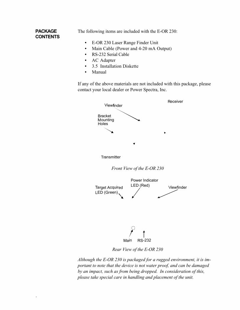
PACKAGE The following items are included with the E-OR 230:
CONTENTS• E-OR 230 Laser Range Finder Unit
• Main Cable (Power and 4-20 mA Output)
• RS-232 Serial Cable
• AC Adapter
• 3.5 Installation Diskette
• Manual
If any of the above materials are not included with this package, please
contact your local dealer or Power Spectra, Inc.
Front View of the E-OR 230
Rear View of the E-OR 230
Although the E-OR 230 is packaged for a rugged environment, it is im-portant to note that the device is not water proof, and can be damagedby an impact, such as from being dropped. In consideration of this,please take special care in handling and placement of the unit.
3
HARDWARE The E-OR 230 is a pulsed laser rangefinder that employs a variety of
DESCRIPTION state-of-the-art electronic technologies. The device uses a fully eye-
safe laser with a 5 nanosecond (ns) pulse of light that strikes a target,
and is reflected back. The rangefinder measures the amount of time
taken for the pulse to travel to the target and back, then converts the
time-of-flight into distance.
The core of the time-of-flight technology is a system that performs
digital time interval measurement. This is a wholly digital system,
primarily implemented in a digital ASIC (Application Specific Inte-
grated Circuit). The system uses digital time domain multiplexing, and
digital resolution enhancement technology, bringing up to 0.1 inch
resolution to the E-OR 230 (patent pending).
The heart of the E-OR 230 s transmitter is a proprietary Pulsed Opti-
cal Source (POS“). The POS is a laser diode actuated by a gallium ar-
senide semi-conductor switch with a very fast, 1 ns rise time. The
pulse of light generated by the POS has a peak power of 10-40 watts,
and is fully eye-safe at the E-OR 230 s trigger rate of 10 kHz.
The E-OR 230 s receiver is composed of a photo diode (which detects
the reflected light pulse), followed by a series of amplifiers and an
analog-to-digital converter that transforms the diode s output to a suit-
able signal for the digital time interval measurement system.
The above subsystems (transmitter, receiver, timer) are all controlled
and coordinated by a powerful micro-controller. This device also man-
ages the user selectable features, such as range gating, the data transfer
rate, etc., as well as the data flows, and I/O port activity.
The E-OR 230 has a variety of external connections that the user
should be aware of. These are described below.
Main CableThe main cable plugs into the rear of the E-OR 230, providing an inter-
face to the power supply and a 4-20 mA output source.
Power. The E-OR 230 requires input power of 8-30 VDC, and uses
a maximum of 6 Watts. The AC adapter that comes with the E-OR
230 (hard-wired to the main cable) is compatible with this requirement.
If you wish to replace the AC adapter, or use another power source, be
sure the source conforms to this requirement. Failure to do so mayresult in damage to the E-OR 230, or worse, cause an electricalinjury (perhaps severe or fatal) to the user.

4
4-20 mA. The analog output of the E-OR 230 uses the factory control
industry standard 4-20 mA. This standard is well suited for transmit-
ting analog data over long distances and through noisy environments.
Access to the 4-20 mA output is available on the main cable, via two
floating leads (red is positive, black is negative).
RS-232The serial port of the E-OR 230 is available for host communications,
for both parameter settings input and data output. The E-OR 230
follows standard protocols for serial communication (detailed later in
this manual); a pinout listing of the RS-232 port is shown below.
Pin Description
1 Not used
2 TX transmit data
3 RX receive data
4 Not used
5 GND signal ground
6 Not used
7 CTS clear to send
8 RTS request to send
9 Not used
HARDWARE The E-OR 230 is extremely simple to operate, requiring only a few
OPERATION basic steps to begin acquiring data. Follow the steps below to get the
E-OR 230 up and running.
1. Connect the main cable (included) to the rangefinder s main connec-
tor, located at the rear side of the unit.
2. Connect the included serial cable to the E-OR 230 and to a personal
computer with a DB-9 serial port (be sure the power to the PC is
switched off). The serial cable is mated, such that one end is desig-
nated for the E-OR 230 and the other for the PC.
3. Plug the AC adapter into a standard 120 VAC wall receptacle.
4. Switch on power to the PC.
The hardware is now set up to take distance measurements, and com-
municate with the connected PC. The only remaining task is to aim the
device at a target. The integrated viewfinder greatly helps in this proc-
ess, especially for objects that are far away and/or small in size.

5
CHAPTER TWO: E-OR 230 WindowsApplication Software
SOFTWARE Included with the E-OR 230 is a Windows application software
INSTALLATION package that is used to set up the range finder, and to display distance
and velocity measurements. Following are installation and operation
instructions.
1. Insert the 3.5 floppy disk included with E-OR 230; open the win-
dow for the floppy drive.
2. Double-click on the Install icon. The installation software will
create a directory* named E-OR 230 and herein copy all files
needed for the application software. This is all that the install pro-
gram does; no existing files (such as SYSTEM.INI) are altered in
any way.
* This directory is installed on the C: drive. If you wish to maintain
the directory elsewhere, simply move it after installation.
SOFTWARE After installation, there will be a new directory on your hard disk,
TUTORIAL named PSI. This directory contains the application software, a con-
figuration file, and two shortcuts, for a total of four file icons.
The software can be launched in one of three modes: 1) as demonstra-
tion software, 2) as application software using COM 1, or 3) as appli-
cation software using COM 2 (COM 3 or COM 4 can also be used;
this will be explained later in the manual). The mode depends on
which icon is used to launch the software:
• To launch a demonstration version of the software, double-click on
the E-OR Demo icon.
• To launch the application software, using COM 1 as the serial port
for the range finder, double-click on the App-COM 1 icon.
• To launch the application software, using COM 2 as the serial port
for the range finder, double-click on the App-COM 2 icon.
The remainder of this tutorial applies to all modes. The wording of the
instructions, however, assume the software is in application mode.

6
1. After the program has been launched, maximize its window. All
windows in the application software comply with Microsoft s
windowing standard, which means all window operations, such as
minimizing, closing, etc., will be immediately familiar to the user.
The picture below shows what now appears on the screen.

7
2. To invoke range finder operation, simply click the On box in the
upper left corner of the screen. The box will show a check mark,
and after a few seconds, both hardware and software will begin op-
erating. As shown in the picture below, the screen now displays
distance and velocity data in their respective windows (both nu-
merically and graphically).
You ve successfully installed and used the E-OR 230 for a distance and
velocity application! The next section further details this software.

8
SOFTWARE The range finder s application software can be customized to suit
OPERATION specific requirements; it can also be used to set various parameters in
the range finder hardware. The following describes these features in
detail.
File Menu The File Menu is used to manage configuration files, invoke data log-
ging, and to exit the program. An image of the File Menu is shown
below.
Configuration files are used to save parameters set in the range finder
software. For example, if two applications require different window
displays, each can be saved to a separate configuration file. Or, if mul-
tiple E-OR 230s require identical hardware settings, a configuration file
can be created to streamline the hardware setup process.
Select the Save Configuration command to save the current software
configuration. Select the Load Configuration command to open a dif-
ferent configuration.
The Save TEXT Data File command (disabled in the initial state) is
used to store a permanent record of range finder measurements. When
this command is invoked, all data points in the E-OR 230 s data buffer
are written to a user-named ASCII text file.
To create a data storage file:
1. Activate the range finder by clicking the On box in the upper left
corner of the screen. Let the range finder run until data storage is
required.
The maximum number of data points that can be stored in the
E-OR 230 s data buffer is 5,000. This means that after this many
data points are stored, data is overwritten, point by point on a
first-in first-out basis. The time interval for overwriting can be de-
termined by dividing the maximum number of data points (5,000)
by the data rate (described later). The result of this computation is
the number of seconds between buffer loops.
2. When it is time to invoke logging, click the On box again.

9
3. Click on the Save TEXT Data File command in the File Menu,
then choose either the As Raw Data or Formatted option. The
program will then prompt the user to name the data file.
4. Name the data file, then click the OK button in the dialog box.
Once a data file has been saved, it can be viewed/edited with any soft-
ware that reads text only files (word processors, spreadsheets, etc.).
Below is a sample data file.
"Power Spectra Data Buffer"
Feet:
50.1
50.3
Err:128
50.5
50.8
The first two lines of the data file are for identification only. Data
points start on the third line.
Note that the above sample file contains an error message. Error mes-
sage codes are listed in the chapter on the range finder s serial interface.
To preserve as much data as possible, the software will resume data
logging after any error that is recoverable (as evidenced by data points
that follow an error message).
The data file has only one column of data, regardless of the number of
windows displayed in the application software. This is because raw
data is used to derive all display data. For example, velocity data is
created by first converting raw data into distance data, then using two
distance points, and the known data rate, velocity is computed.
If the As Raw Data option is selected, each number must be trans-
formed into a meaningful number. To do this, input the raw number
(X) to one of the following formulas:
X * 0.002135 = distance in feet
X * 0.007005 = distance in meters
The last item in the File Menu is the Exit command. Select this
command to close the program. A shortcut for this command is shown
to the right of the command. Invoke this key sequence to close the
program more quickly, or, if keyboard usage is preferred over mouse

10
usage. (Several other shortcuts are available in this program; any menu
command with a named key sequence operates similarly. Also, the
underlined letter in each command provides a keyboard shortcut.)

11
Display Menu The Display Menu is used to create new display windows. An image
of the Display Menu is shown below.
To create a new window, simply select one of the four commands
above. After selecting a display, a new window will appear. Each
display window has a display options dialog box, which is accessed by
double-clicking anywhere in the display area of the window. Follow-
ing is a picture and description of each of these dialog boxes. Any
window parameter not shown in the display options dialog box is set
automatically by the software.
Position Meter
The Position Meter displays distance in numerical format. Distance
units are changed by clicking the button next to the desired unit of
measurement.
The Averaging option lets the user specify the number of samples used
for a moving average. The default setting of 1 results in no averaging.
To change to a different number, simply click the up or down arrow
until the desired number is displayed. Alternatively, the number can
be selected with the mouse, by pressing the Tab key, or by pressing
the Alt + A key sequence, or it can be changed via keyboard input.
Up to 40 samples can be used for averaging.

12
Position Graph
The Position Graph displays distance in graphical format, as a function
of time. Distance units can be changed by clicking in the Display area,
on the button next to the desired unit of measurement.
The number of averaging samples can be changed by clicking the up or
down arrow in the Averaging area, or by highlighting the number and
changing it with keyboard input.
Set the minimum and maximum values for the Y-axis by clicking the re-
spective up and down arrows in the Range area. The Y-axis grid set-
tings are changed in the Grid area.
The Mode area is for specifying the line style of the graph. The Line
option sets the graph to display a plain line; the Solid option sets the
graph to display a filled line.
The Spacing area is for setting one of the variables that specify the
length of the X-axis. The other two variables are the data rate and the
width of the graph window. Essentially, the graph displays data by
drawing one, two, or three pixels (depending on the Spacing setting),
for each data point taken by the range finder. The time taken for one
sweep of the X-axis depends on all of the above variables. For exam-
ple, to set the X-axis to take as long as possible for one sweep, the
window must be as wide as the computer screen will allow, the data
rate must be at the lowest setting (1.22 Hz), and the Spacing must be
set at x1. The x2 and x3 settings reduce the time of one X-axis
sweep by 50% and 67%, respectively.

13
Velocity Meter
The Velocity Meter displays velocity in numerical format. Note that
this reportage of velocity is not necessarily the velocity of the target
being measured. This is because the target may not be moving at the
same angle, relative to the range finder, that the pulsed light is moving
(which is perpendicular within 3… to the face of the range finder).
To ensure that velocity is reported correctly, place the range-finder directly in line with the angle of motion of the target ob-ject.
Velocity units can be changed by clicking the button next to the desired
unit of measurement.
The Spread option lets the user specify the sensitivity of velocity cal-
culations. The spread value specifies the number of points between
velocity calculations. For example, a spread of 2 means that the cur-
rent point and the immediately preceding point are used to compute
velocity; a spread of 40 uses the current point and the 39th preceding
point. Use a small spread in applications where a brief change in ve-
locity is important; use a large spread in applications where brief
changes in velocity are unimportant. To change to a different number,
simply click the up or down arrow until the desired number is dis-
played. The spread can be between 2 and 40 samples.

14
Velocity Graph
The Velocity Graph displays velocity in graphical format, as a func-
tion of time. Velocity units can be changed by clicking in the Display
area, on the button next to the desired unit of measurement.
The Spread option works identically to that in the Velocity Meter.
The Range, Grid, Spacing, and Mode options work identically to those
in the Position Graph.
Control Menu The Control Menu is used to manage a variety of general program set-
tings. An image of the Control Menu is shown below.
The Status Line command toggles the display of the Status Line,
which, when checked, appears at the bottom of the screen, and gives
brief explanations of all menus and menu commands when the mouse is
positioned over the respective menu or command.
15
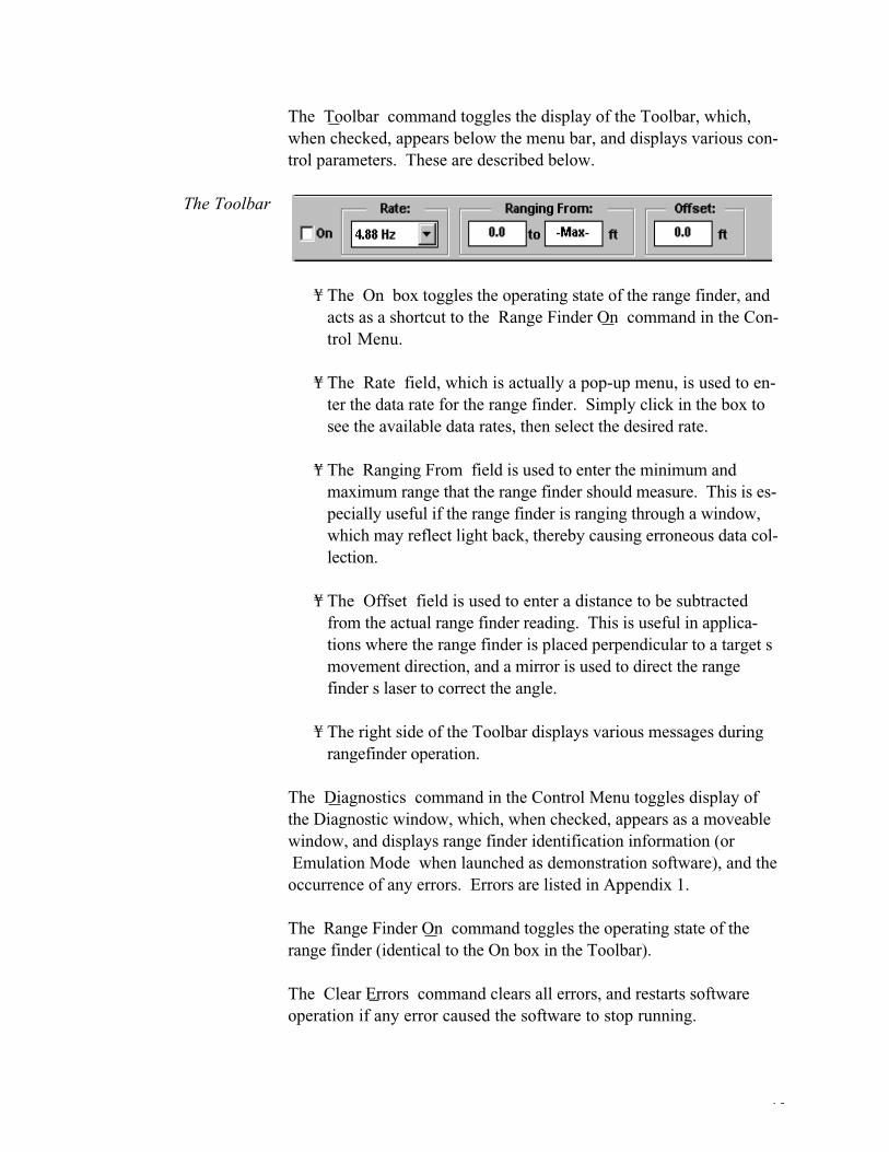
The Toolbar command toggles the display of the Toolbar, which,
when checked, appears below the menu bar, and displays various con-
trol parameters. These are described below.
The Toolbar
¥ The On box toggles the operating state of the range finder, and
acts as a shortcut to the Range Finder On command in the Con-
trol Menu.
¥ The Rate field, which is actually a pop-up menu, is used to en-
ter the data rate for the range finder. Simply click in the box to
see the available data rates, then select the desired rate.
¥ The Ranging From field is used to enter the minimum and
maximum range that the range finder should measure. This is es-
pecially useful if the range finder is ranging through a window,
which may reflect light back, thereby causing erroneous data col-
lection.
¥ The Offset field is used to enter a distance to be subtracted
from the actual range finder reading. This is useful in applica-
tions where the range finder is placed perpendicular to a target s
movement direction, and a mirror is used to direct the range
finder s laser to correct the angle.
¥ The right side of the Toolbar displays various messages during
rangefinder operation.
The Diagnostics command in the Control Menu toggles display of
the Diagnostic window, which, when checked, appears as a moveable
window, and displays range finder identification information (or
Emulation Mode when launched as demonstration software), and the
occurrence of any errors. Errors are listed in Appendix 1.
The Range Finder On command toggles the operating state of the
range finder (identical to the On box in the Toolbar).
The Clear Errors command clears all errors, and restarts software
operation if any error caused the software to stop running.

16
Selecting the Program Options command causes a dialog box to
open. In this dialog box, the default measurement units can be selected.
The default unit is immediately changed in the Toolbar, and new win-
dows will be initialized with the new default unit.
Also in the Program Options dialog box is a box to disable the
screen saver. Checking this box will disable the Windows standard
screen saver, as well as most third party screen savers. This feature is
helpful if the program is running constantly with no mouse or key-
board action, and a user needs to periodically view range finder data.
The last command in the Control menu is 4-20 mA Options
When this command is selected a dialog box opens. This dialog box is
shown below.
To enable 4-20 mA output, click on the top box. The Autostart with
4-20 mA Output box will set the range finder to always enable the
4-20 mA port upon power-up. This feature enables range finder op-
eration without the need for a computer to be connected.
The Range area of the dialog box is for entering 4-20 mA endpoints. In
these boxes, enter the minimum and maximum ranges to be measured.
The output of the 4-20 mA port will reflect the entered endpoints,
with intermediate current levels representing linear data between the
endpoints.
17
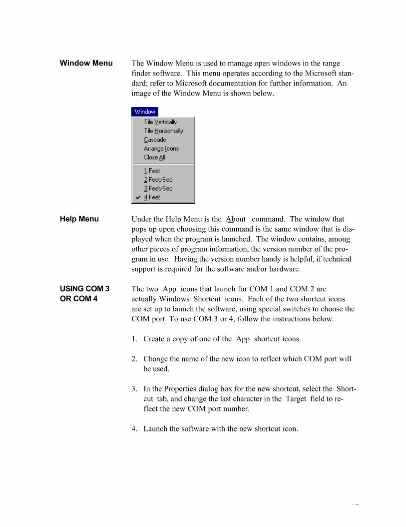
Window Menu The Window Menu is used to manage open windows in the range
finder software. This menu operates according to the Microsoft stan-
dard; refer to Microsoft documentation for further information. An
image of the Window Menu is shown below.
Help Menu Under the Help Menu is the About command. The window that
pops up upon choosing this command is the same window that is dis-
played when the program is launched. The window contains, among
other pieces of program information, the version number of the pro-
gram in use. Having the version number handy is helpful, if technical
support is required for the software and/or hardware.
USING COM 3 The two App icons that launch for COM 1 and COM 2 are
OR COM 4 actually Windows Shortcut icons. Each of the two shortcut icons
are set up to launch the software, using special switches to choose the
COM port. To use COM 3 or 4, follow the instructions below.
1. Create a copy of one of the App shortcut icons.
2. Change the name of the new icon to reflect which COM port will
be used.
3. In the Properties dialog box for the new shortcut, select the Short-
cut tab, and change the last character in the Target field to re-
flect the new COM port number.
4. Launch the software with the new shortcut icon.

18
CHAPTER THREE: RS-232 Interface
GENERAL The E-OR 230 has a built-in RS-232 interface for communicating
DESCRIPTION with other serial devices. With this interface, a program can be written
to acquire range finder distance measurements, and to change opera-
tional settings for the device. Following is a description of the serial
interface, which is intended for use by experienced programmers. In
the absence of RS-232 programming experience, a general purpose
communications package, such as HyperTerminal, can be used to
communicate with the range finder.
RS-232 To enable serial communication with the E-OR 230, the first task is to
PROTOCOL set the communication s protocol in the host machine to match that of
the range finder. These settings are listed below.
Baud Rate: 19,200 bps
Parity: None
Data Bits: 8
Stop Bits: 1
Handshaking: None
After communications have been established, interactions with the
range finder take the form of host commands (described below) and re-
turned data. As part of the protocol, all commands must have no blank
spaces between the initial character and the termination character. The
termination character must be either a carriage return <CR>, a carriage
return and a line feed <CR><LF>, or a null character <0>.
Any response from the range finder, evoked by a host command, will
include a carriage return <CR> at the end. Also, each data point sent
during ASCII data streaming is followed by a carriage return <CR>.

19
HOST Below is a list and description of the serial commands available with
COMMANDS the E-OR 230. Some commands require an input parameter; this is de-
noted at the end of the command with a <n> . In all cases, n is an
integer.
ID Get instrument ID; returns name and firmware version number
SX Sets all parameters to default values
SA<n> Sets the number of 10kHz raw data points to average for each
reading (1 255); the default is 16
SR<n> Sets the rate, as a divisor of 10kHz, at which to stream data; the
default is 1000
SF<n> Sets the data format: 0=ASCII, 1=Binary, 2=Binary with sync tags;
the default is 0
SL<n> Sets the low limit for range (range gating), in counts (3.28 inches per
count); the default is 30 set n to 0 to turn off range gating
Note: The SL (and SX ) command writes <n> to the range finder s
EEPROM. This parameter stays in force through range finder power
cycles; it is removed only upon execution of the XX command, and
can be changed by executing subsequent SL or SX commands.
This is especially important to remember if there are multiple users of
the range finder (i.e., if another user issues an XX command, the
range gate reset may go unnoticed by the original user).
SZ<n> Enables 4-20 mA output during data streaming: 1=enable, 0=disable;
the default is 0
Q<c> Queries the state of above S commands (c = A, R, F, L, or Z);
returns the <n> value of the respective command
QQ Queries error condition; returns all errors since last QQ command
The QQ command can return any of the below listed errors:
Error: Syntax Error
Error: Bad Parameter
Error: Inconsistent Parameters
Error: Command(s) Ignored
Error: EEPROM Error

20
EO<n> Stores the offset to subtract from each reading into the EEPROM, in
counts (0.0256 inches per count);
VO Verifies offset; returns the <n> value of the EO command
EX<n> Sets lower value for 4-20 mA output, in counts (3.28 inches per count)
EY<n> Sets upper value for 4-20 mA output, in counts (3.28 inches per
count)
EZ<n> Enables 4-20 mA output at power-on: 1=enable, 0=disable
VX, VY, Verifies the 4-20 mA parameters; each returns the respective <n>
VZ value
DD Acquires an individual data point, as an ASCII character or as
a 3-byte binary number
Note on error reporting: when an error occurs in the range finder, it is
reported upon receipt of a DD command. In ASCII format, the error is
reported as Err: followed by a decimal error byte. In binary format,
the error is reported as FF in the most significant byte. The error
number (presented as a hex number in the least significant byte in bi-
nary format) is the sum of one or more of the numbers below, indicat-
ing which error(s) occurred:
1: ERR_WILDPT wild point error bit
(generated by make_data_point())
8: ERR_SETTLE AGC hasn’t settled after attenuater switch
(not from FPGA)
64: ERR_MISFIRE misfire error bit, set by the FPGA
128: ERR_OVERRNG over range error bit, set by the FPGA
Example: Err:136 (FF0088 in binary) means that both the 2nd and 4th
errors occurred.
DS Starts data streaming, as ASCII characters or as 3-byte binary numbers
XX Stops data streaming

21
APPENDIX 1: Diagnostic Window Errors
Below are the Communications Errors that can occur:
OH overrun in hardware
OV overrun of buffer
PA parity
FR framing
BR break detect
TO timeout
Below are the Hardware Errors that can occur:
MIS start error (laser misfire)
RAN overrange
WIL wild points
SET agc settling
SYN data stream out of synch

22
Index
4-20 mA, 2, 3, 4, 15, 18, 19
AC adapter, 3Averaging, 10, 11
COM ports, using different, 16Configuration files, 8Configuration, Save, 8Control Menu, 13
Diagnostics, 14Display Menu, 10
File Menu, 8
General Description, 1
Hardware Description, 3Hardware Operation, 4
keyboard shortcuts, 9
Main Cable, 2, 3
Offset, 14
Position Graph, 11Position Meter, 10Power, 3Program Options, 15
Ranging parameters, 14Rate, 14RS-232, 1, 2, 4, 17RS-232 commands, 18RS-232 protocol, 17
serial port, 4, 5Software Installation, 5Software Operation, 8Software Tutorial, 5Spread, 12Status Line, 13
Toolbar, 14
Velocity Graph, 13Velocity Meter, 12
Window Menu, 16