e-mw100 series - spray painting · pdf filee-mw100 series kema 0344 en50050 ... this...
TRANSCRIPT

Instruction Manual
Electrostatic air hand gun E-spraySeries
E-MW100 series
KEMA 0344 EN50050 BVS 06 ATEX E 049
GroupⅡ category 2 gas atmosphere equipment Suitable for use in Zone 1
This instruction manual contains IMPORTANT WARNINGS, CAUTIONS and
instructions for safe operation. Before operation, be sure to read this
instruction manual thoroughly and understand the equipment so that you can use
it safely and effectively for a long time.
Keep this booklet in an appropriate place for immediate reference.

Important information - Safety Precautions This electrostatic air hand spray gun is exclusively used for electrostatic painting (we call it
electrostatic spray gun from now on). Be sure to read and understand this instruction manual. Both the supervisor and operator shall be fully knowledgeable about the requirements stated
within this instruction manual, including important warnings, cautions and proper method of operation.
Wrong operation (mishandling) can cause serious bodily injury, death, fire or explosion.
This electrostatic spray gun is used along with related electrostatic controller (E-SC24L-EX)
series: option) and paint pump (e.g. DPS-90), etc. When using related equipment, also read instruction manuals for those products.
Keep this booklet in an appropriate place for immediate reference.
1. About safety Pay special attention to items which are shown by below marks and symbols.
Symbols and marks have the following meanings.
Indication of warnings and cautions
WARNING Indicates a potentially hazardous situation which, if not avoided, will result in serious injury or loss of life.
CAUTION Indicates a potentially hazardous situation which, if not avoided, may result in minor or moderate injury or property damage.
Examples of warnings and cautions
Indicates [You must be careful]. We will explain briefly in or near the symbol. (The example on the left is [Be careful about electric shock]).
Indicates [You must not do]. We will explain briefly in or near the symbol. (The example on the left is [Do not touch]).
Indicates [You must do]. We will explain briefly in or near the symbol. (The example on the left is [Be sure to ground it]).
We shall not be responsible for any injury or damage caused by disregard of warnings, cautions or instructions.
Indicates notes which we ask you to observe. They are helpful to fully achieve performance and functions of the equipment. Important
①

Warnings and cautions for safe operation
WARNING
Fire and Explosion
Avoidance of fire and explosion at painting site
Never install it at a site with flammable goods or bring flammable goods like lighters. Paints and organic solvents are flammable, able to cause fire. Never use the following Halogenated Hydrocarbon solvents which can chemically react with spray gun parts (aluminum parts) etc., crack and melt them. Improper solvents: methyl chloride, dichloromethane, 1,2-dichloroethane, carbon
tetrachloride, trichloroethylene, 1.1.1.-trichloroethane (Be sure that all fluids and solvents are compatible with gun parts. We are ready to supply a material list used in the gun on request.)
Avoidance of fire caused by grounding failure
Be sure to keep hanger or conveyor clean without paint stuck on it and keep them conductive. Incomplete grounding, dirty hanger or conveyor cannot conduct electricity, and static electricity accumulates, resulting in fire accident by spark discharge.
Store paint and solvent in a metallic container which is grounded. Poorly grounded conductor can accumulate static electricity, causing fire accident by spark discharge. If you are forced to place conductive goods such as fluid container and fluid supply pump within 3m from the gun, be sure to ground them without fail.
Securely ground electrostatic controller (A class grounding: less than 10Ω). As you ground the electrostatic spray gun by contacting electrostatic controller through low voltage cable, incomplete grounding can accumulate static electricity on spray gun, causing fire accident by spark discharge or bodily injury by electric shock.
A class grounding
(Good!) ×(Bad!)
Be sure to contact metallic points by makingcontact points knife-edged or sharp-pointed.
②

Avoidance of fire by ignition of paints and solvents
Be sure to turn off electric source of electrostatic controller (E-SC24L-EX) series: option) before cleaning inside of fluid passages. As paints and solvents are flammable and have low flash points, they can catch fire if there is spark discharge in and around painting site.
Spray distance between work-piece and painting equipment must be over 10cm. If the distance is less than 10cm, spark discharge can occur and paint can catch fire.
Never use lacquer paints. Lacquer paints have low flash points and can catch fire.
Do not cover electrostatic spray gun with anti-dust sheet. Static electricity accumulated on sheet can discharge and solvent gas can catch fire.
Wrong operation
Avoidance of wrong use
Never point toward human or animal during spraying. If done, it can cause inflammation of eye or skin and bodily injury. Never use gas other than compressed air. If done, it can cause fire or poisoning accident. Never use at higher than max. operating pressure (refer to specifications on page 2). Tip of fluid needle has a sharp point. Do not touch the tip of fluid needle during maintenance for the protection of the human body.
Avoidance of wrong operation
Before inspecting, cleaning, disassembling or assembling electrostatic spray gun, be sure to turn off electric source of electrostatic controller (E-SC24L-EX) series: option), interlocked equipment and equipment and fully release air and fluid pressure in the following procedure. If not, it can cause bodily injury by wrong operation.
Job 1) Turn off electric source of electrostatic controller (E-SC24L-EX) series: option) . Job 2) Stop supply of compressed air, paint and solvent to spray equipment.
Job 3) Turn electrostatic spray gun downwards, pull trigger, operate fluid needle and fully
release air pressure and fluid pressure.
③

Bodily protection
Protection from solvents, air and fluid pressure
Use spray booth and do the painting job in a well-ventilated place. Painting and cleaning jobs in a poorly ventilated site can cause organic solvent poisoning and ignition. Always wear protective tool such as protective goggles and mask. If not, cleaning liquid can touch eyes and skin, causing inflammation. If you feel something wrong with eyes or skin, immediately consult with a doctor. We recommend you to wear earplugs for your safety. Noise level can reach over 85dB(A) depending on operating and working conditions. Be sure to turn off electric source of electrostatic controller or multi-gun control system and release fluid and air pressure before cleaning, disassembling or doing maintenance job or during stoppage of job. If not, remaining pressure can cause bodily injury through wrong operation and spattering of cleaning liquid. Be sure to follow [Avoidance of wrong operation ] on page ③ in order to turn off electric source, and release air and fluid pressure.
Protection from static electricity
Be sure to wear electrostatic shoes(resistance figure 105~10
8Ω、JIS T 8103) and anti-charge
working clothes(JIS T 8118). If not, static electricity can accumulate on human body and cause bodily accidents by electric shock.
Operators must not wear metallic things such as watch or key holders during operation. If done, static electricity can accumulate on them and you will get an electric shock. If you wear glasses with metallic frame and approach
the gun, you can get an electric shock. Before approaching spray equipment, turn off electric source of electrostatic controller or multi-gun control system.
Operator must always hold electrostatic spray gun with bare hand or glove having a large hole at palm position. As human body is grounded through the handle of electrostatic spray gun, static electricity can accumulate on human body and cause bodily harm by electric shock if operator holds the gun handle with normal glove.
When you turn off main electric source switch in order to stop the gun operation in an emergency, it takes about 5 seconds till the electric potential of electrostatic spray gun goes down to a safe level. Don’t try to touch the pin electrode at tip of gun during that period.
Anti-charge workingclothes
Electrostatic shoes
Protection of human body If operators pull the trigger many times during operation, it may cause repetitive strain injury. Be sure to take a rest if you feel tired.
④

Others
Never use altered parts or other than genuine parts when parts are damaged or worn out. If done, it can cause failure of the gun, accidents or bodily injury.
Be sure to install a fire extinguisher at painting site.
Make sure that the equipment has stopped before you enter the working range of other painting equipment (robot, reciprocator, etc.). If not, moving robot or reciprocator can injure you.
Never use for food or chemicals. If done, erosion in paint passages can cause accidents, and foreign matter can enter.
extinguisher
CAUTION
Maintain safety and functions of electrostatic spray gun
Be sure to observe the following in order to maintain safety and functions of electrostatic gun: 1) Be sure to inspect and do the maintenance in accordance with 5. “Inspection and maintenance”(P.12). 2) Never immerse electrostatic gun body in cleaning thinner when cleaning gun. Clean electrostatic gun in accordance with 4.5 “Job-3 clean electrostatic air hand gun body and low voltage cable”(P.10). 3) Be sure to install and handle low voltage cable in accordance with 4.1 ”precautions on installation and handling of low voltage cable” (P.5). 4) Handle electrostatic gun with care in order not to give it a jolt. Especially take care not to drop, hit or trample on it or move work piece or hanger by tip of gun. If done, it can fail electrostatic spray gun.
⑤

Contents
1. Specifications··············································· P. 2
2. Check the product········································ P. 3
3. Names and functions of each section········ P. 4
4. Connection and setting ······························· P. 5
5. Inspection and maintenance······················· P. 12
6. Disassembling and assembling·················· P. 16
7. Parts list ························································ P. 23
8. Problems and remedies (troubleshooting)············· P. 24
Note:
The operator and the supervisor of this electrostatic gun must fully read and understand Chapters
from 1 to 3 and 4.3 to 4.5.
Only the supervisor and / or other equally qualified personnel, having fully read and understood
the contents of this instruction manual, can take care of matters related to Chapter 4 to 8.
‐1‐

1 Specifications < For Operator and Supervisor >
1.1 Important specifications
Ambient temperature range 5~40
Ambient humidity range Less than 70%RH
Max. operating pressure Air:0.68 MPa, Paint:0.35MPa
85dB(A) : at 1m backward from gun, 1.6m height Noise level (LAeqT) inlet air pressure 0.35MPa (recommended air pressure)、 GroupⅡ, category 2 gas atmosphere equipment Suitable for use in zone1
EX Spec. (CE ATEX regulation)
Ⅱ2G 0.24mJ EN50050
BVS 06 ATEX E 049 KEMA 0344
1.2 Main specifications
Items Specifications Remarks No.
1 External charging system Electrostatic Charging method 2 Built-in high voltage booster Cartridge system High voltage generation 3 Max. operating voltage During no-load -50kV
4 Max. operating current Initial setting 150μA
5 Not including external electrode Dimensions L×W×H 186×64.6×226.9
6 Mass Without low voltage cable and fluid tube 530g
7 Electrostatic controller E-SC24L-EX Applicable electrostatic controller Not included in this model
8 Air nipple / fluid nipple thread size G1/4 (air nipple)G3/8 (fluid nipple) Air hose and paint hose are not included
10 Applicable paint*1) Water based paint
W L
H
1.3 Specification of atomization Model code
mark indicates cable length ⇒ “X” :10m, “Y” : 15m, “Z” : 20m
Atomization No.
option E-MW50-11C5
Air cap model code 1 C5
Fluid nozzle dia. 2 Φ1.1
< How the Electrostatic Air Spray Gun Works > The air hose supplies air to the spray gun. The air atomizes the fluid being sprayed. The Electrostatic controller supplies low
voltages to power booster cartridge in the Electrostatic Air Spray guns. Electricity supplied by the electrostatic controller is converted to high voltage by a cartridge (booster circuit) inside the gun. The
high voltage is supplied to tip of the external electrode. The pump supplies fluid to the hose and gun, where the fluid is electrostatically charged as it passes the external electrode. The charged fluid is attracted to the grounded work piece, wrapping around and evenly coating all surfaces.
‐2‐

2 Check the product < For Operator and Supervisor >
This product consists of an electrostatic gun including the following accessories. Before use, be sure to confirm that there is no shortage or damage. If there is any shortage or damage, please contact the shop which sold it to you.
Name Contents
Electrostatic gun
Low voltage cable
(1) Special screwdriver to tighten needle packing set
(2) Binding tube to bind air hose and low voltage cable
(3) Cleaning brush to clean
electrostatic gun exclusively (to clean surface)
(4) Cleaning brush to clean electrostatic gun exclusively (to clean small holes)
Acce
ssor
ies
(5) Instruction manual (this one)
‐3‐

3 Names and functions of each section < For Operator and Supervisor >
3.1 E-MW100 series
Fluid adj. set Adjusts fluid output.
Atomizing head(air cap, fluid nozzle) Atomizes paint with air.
Fluid nipple Connects to fluid hose (G3/8).
Low voltage connector Supplies electricity from low voltage cable
(AC24Vpp).
Handle Releases charged electricity on human body. Be sure to hold with bare hand.
Air nipple Connects to air hose (G1/4).
Pattern adj. set with lock Adjusts pattern width.
External electrode Charging electrostatic to atomized fluid Quick removable to change 2 kinds of electrode depending on painting
process.
‐4‐
4 Connection and setting < For Supervisor >
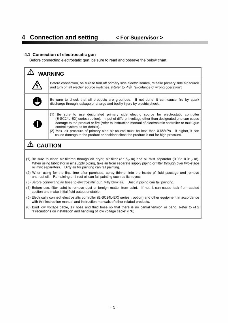
4.1 Connection of electrostatic gun Before connecting electrostatic gun, be sure to read and observe the below chart.
WARNING Before connection, be sure to turn off primary side electric source, release primary side air source and turn off all electric source switches. (Refer to P.④ ”avoidance of wrong operation”)
Be sure to check that all products are grounded. If not done, it can cause fire by spark discharge through leakage or charge and bodily injury by electric shock.
(1) Be sure to use designated primary side electric source for electrostatic controller (E-SC24L-EX) series:option). Input of different voltage other than designated one can cause damage to the product or fire (refer to instruction manual of electrostatic controller or multi-gun control system as for details).
(2) Max. air pressure of primary side air source must be less than 0.68MPa. If higher, it can cause damage to the product or accident since the product is not for high pressure.
CAUTION
(1) Be sure to clean air filtered through air dryer, air filter (3~5μm) and oil mist separator (0.03~0.01μm). When using lubricator in air supply piping, take air from separate supply piping or filter through over two-stage oil mist separators. Dirty air for painting can fail painting.
(2) When using for the first time after purchase, spray thinner into the inside of fluid passage and remove anti-rust oil. Remaining anti-rust oil can fail painting such as fish eyes.
(3) Before connecting air hose to electrostatic gun, fully blow air. Dust in piping can fail painting. (4) Before use, filter paint to remove dust or foreign matter from paint. If not, it can cause leak from seated
section and make initial fluid output unstable.
(5) Electrically connect electrostatic controller (E-SC24L-EX) series:option) and other equipment in accordance with this instruction manual and instruction manuals of other related products.
(6) Bind low voltage cable, air hose and fluid hose so that there is no partial tension or bend. Refer to (4.2 “Precautions on installation and handling of low voltage cable” (P.6)
‐5‐

4.2 Precautions on installation and handling of low voltage cable
Be sure to read and observe the below cautions before connection, installing and handling low voltage cable.
CAUTION
(1) Tighten cap nut of low voltage cable and securely connect low voltage cable. If tightening is incomplete, paint and solvent can enter inside of connector causing failure of electrostatic gun and electrostatic controller.
(2) Be sure to observe the following about binding low voltage cable of electrostatic gun in order to maintain its
strength and durability. ① Never bind cable within about 50cm from gun handle of electrostatic gun. ② When pointing electrostatic gun upwards, downwards, left and right, carefully bind low voltage cable with air
hose and fluid hose so that there is no strong bend or tension on low voltage cable. ③ When binding over 50cm from gun handle, bind with attached spiral tube or vinyl tape at over 5cm intervals,
and do not bind too tightly. Especially do not bind continuously with vinyl tape or wide spiral tube. If done, bound section becomes like a hard bar, and it is broken at both ends, then it can cause disconnection or damage of cable and hose.
(3) Do not bind low voltage cable, air hose or fluid hose, or handle electrostatic gun so that there is forced bend or
strong tension during painting.. If done, it can reduce strength and cause disconnection. (4) Pay attention not to trample on low voltage cable. It can disconnect when you trample on it especially on grid floor
of the spray booth. (5) Do not continuously bind low voltage cable itself (especially near electrostatic gun connector) with vinyl tape etc., to
increase strength or avoid dirt. If done, it can conversely reduce strength and cause disconnection. (6) Do not immerse low voltage cable in solvent or paint for a long time. If done, it can greatly reduce strength and
lifetime of low voltage cable. (7) After cleaning low voltage cable, be sure to remove solvent attached to surface, or blow with air. (8) Do not use metallic binding band. Metallic one can accumulate static electricity and cause electric shock.
Low voltage cable
Bind low voltage cable lighterthan air hose and fluid hose sothat there is no strong tensionon low voltage cable wheninclining gun up or down
Over 5cm intervals from 50cm distance
Tension can causebend (can bedisconnected)
Low voltage cable
Do not bind continuously withvinyl tape or with spiral tubelike this.
‐6‐

(1) Standard connecting example of E-M15B series spray gun
Necessary equipment
Electric source AC-240V
Air hose ex.) AHU-8 5m
Electrostatic controller E-SC24L-EX (option)
First class grounding less than
10Ω ground resistance
G3/8
G1/4
G1/4
Air source
Compressor
Air filter
Air to operate paint pump
Air regulator
Paint pump ex.) DPS-90 : (option)
Low voltage cable
(option)
Air regulator
G3/8
Air hose set ex.) AHU-8 10m
Fluid hose set ex.) PHN-6 10m
‐7‐

4.3 Check grounding < For Operator and Supervisor > Job-1 Ground all conductive objects within 3 m from electrostatic hand gun.
WARNING Ground all conductive objects within 3m from electrostatic gun to avoid electrostatic electric accidents (electric shock and fire).
Job-2 Turn on electric source of electrostatic controller (E-SC24L-EX series : option) and check that ground failure does not display. (Regarding turning on electric source and failure display, refer to instruction manual of electrostatic controller).
4.4 Setting spray conditions < For Supervisor >
Important
This gun is only use of vertical pattern. If this spray gun is used with horizontal
pattern use, the external electrode will be dirt with paint and will cause paint
defects.
Use of horizontal pattern Use of vertical pattern
(1) Air pressure
Adjust air regulator
(2) Fluid output / pattern width
Adjust fluid output by fluid pressure adjustment and locked fluid adj. knob and adjust pattern width by
pattern adj. set.
(3) Check spray distance
Set spray distance at about 200~300mm in order to get proper electrostatic effect.
‐8‐

Hints about electrostatic painting
Bad penetration into recessed section Too much bounce back and paint buildup on protruded section
Spray pressure Increase Spray pressure Increase
Spray distance Closer Spray distance Closer Pattern width Smaller Pattern width Smaller Voltage Decrease Voltage Decrease
Spray recessed section first
4.5 Cleaning after painting job is finished < For Operator and Supervisor >
WARNING
(1)After painting job is finished, be sure to fully release air pressure and fluid pressure and turn off electrostatic controller (E-SC24L-EX series : option) (2)Before cleaning fluid passage (spraying thinner), be sure to turn off electrostatic controller (E-SC24L-EX series:option). If not, it can cause ignition and great danger
Job-1 Clean fluid passage (spray thinner) Spray till cleaning thinner becomes transparent.
Job-2 Clean atomizing head
Remove and clean air cap cover and air cap (As for details, refer to 6. “Disassembly and assembly” on page 17
Spraying Spray recessed section first Spraying
OK if it becomes transparent
By hand By hand
Air cap cover
Air cap
‐9‐

Job-3 Clean electrostatic air hand gun and low voltage cable
In order to use electrostatic gun for a long time, wipe off surface of electrostatic gun and low voltage cable with soft cloth soaked with cleaning thinner and cleaning brush (to clean surface). After cleaning is finished, be sure to blow surface of gun and low voltage cable with air and dry up attached thinner.
‐10‐

CAUTION
(1) When the situation forces you to clean electrostatic gun with thinner gun, be sure to observe the following. If not, it can fail electrostatic gun.
a) After cleaning with thinner gun, be sure to blow with air and dry up thinner attached to surface of electrostatic gun and low voltage cable. As thinner can enter air passage of electrostatic gun during cleaning with thinner gun, be sure to spray air through electrostatic gun (dry air) and blow remaining thinner out.
b) Do not spray thinner gun for a long time. Especially do not focus on one spot.
c) Do not spray thinner gun directly to the following spots.
① Connector of low voltage cable
② Nail of trigger
③ Air hole of air cap ④ Inside of air nipple
(2) What you must never do Never immerse electrostatic gun body or low voltage cable in cleaning thinner. If done, thinner can enter air
passage and high voltage generator in gun, failing electrostatic gun and electrostatic controller or disconnecting low voltage cable for a short time due to its deterioration.
①
②
③
④
Low voltage cable
‐11‐

5 Inspection and maintenance < For Supervisor > Only the supervisor and / or other equally qualified personnel, having fully read and understood
the contents of this instruction manual, can take care of matters related to Chapters 5.
Be sure to observe the following inspection standards to achieve functions safely and fully.
WARNING Before inspection and maintenance, be sure to turn off electric source of electrostatic controller (E-SC24L-EX series:option) and fully release air pressure and fluid pressure. (Refer to P.④ ”avoidance of wrong operation”).
CAUTION Never immerse electrostatic gun or low voltage cable in cleaning thinner. Clean them in accordance with 4.5 ”Job-3Clean electrostatic gun and low voltage cable” (P.10, 11). If not, it can affect safety and performance of the products.
5.1 Daily inspection and maintenance 1) Daily inspection items
Where to inspect Part name Contents Purpose Remedies No
External electrode
Tip external Visually check for bend or breakage
Avoid painting failure and low transfer efficiency 1 Replace part electrode
Visually check 2 Fluid nozzle Tip section Avoid painting failure Replace part deformation and damage
Center and horn holes
Visually check 3 Air cap Avoid painting failure Replace part deformation and damage
Avoid painting failure, electrostatic accident by failing to stop charge
Electrostatic gun
Check for air leakage Refer to 8.1”Painting equipment” (P.24) 4 Each section (by leaking sound)
Visually check for fluid leakage from tip of fluid nozzle
Refer to 8.1 ”Painting equipment” (P.24) 5 Fluid nozzle Tip section Avoid painting failure
Visually check if charge lamp lights up and gun is charged
Avoids painting failure and low transfer efficiency
Refer to 8.2 ”Electrical problems” (P.25) Charge lamp
Electrostatic controller 6
Display lamp of electric current figure for painting
Refer to 5.1 2) ”daily inspection” Visually check if current figure
exceeds normal figure. Avoids painting failure and low transfer efficiency Clean fluid passage of
gun (P12).
Avoid output failure, electric shock or fire due to disconnection of low voltage cable
Low voltage cable
Visually check for excessive strain on low voltage cable
Refer to 4.1”Low voltage cable installation” (P.6). 7 The whole cable
2) Daily inspection items
Where to inspect Part name Contents Purpose
Fluid passage
Avoids painting failure and low transfer efficiency due to electric leakage from paint buildup 1 Clean fluid passage of gun with thinner Electrostatic gun
Avoids low transfer efficiency due to electric leakage 2 Electrostatic gun Surface Remove paint attached to surface
3 Low voltage cable Surface Remove paint attached to surface Avoids short cable lifetime
4 Fluid hose/air hose Surface Remove paint attached to surface Avoids short hose lifetime
‐12‐

5.2 Periodical inspection items 1) Weekly periodical inspection(appearance) (*handle : handle、barrel tip body of gun[plastic])
Part name
Where to inspect
How to inspect Contents Standards Purpose Remedies No
1 Avoids failure of electric parts in gun and electrostatic controller due to paint and thinner inside.
connection between handle
Electro- static gun
Contact the shop which sold it to you and ask for repair.
Check for clearance No clearance Visually check and ※
barrel※
2 connection between electro-static gun and local connector
Tighten low voltage cable nut. Refer to Check for
looseness No looseness
Tighten and check
Avoids failure of electrostatic controller 6.4「Remove and fit low
voltage cable」(P.22). Low voltage cable 3 Replace low voltage
cable. Refer to Avoids failure of output and electric shock or fire due to disconnection of cable
Check for crack or swelling.
outer cover of cable None Visually check 6.4「Remove and fit low
voltage cable」(P.22). 4 Electro-
static controller
Under charged condition, bring tip of gun close to grounded metal.
Contact the shop which sold it to you and ask for repair.
Check if OCR
operates
OCR must operate
Checks function of safeguard. OCR lamp
2) Periodical inspection(inspect electrostatic gun and cable individually) Part
name Where to inspect Cycle Contents Purpose Remedies No
1 Avoids electric shock and fire due to disconnection of cable
Replace low voltage cable Refer to 6.3「Remove and fit low voltage cable」(P.22)
Low voltage cable
500Hr Conductivity and isolation of each section
Check as per 5.4 ”Periodical inspection” 1) (P.14)
2 Maintain performance of gun Contact the shop which sold it to you and ask for repair.
Check as per 5.4”Periodical inspection” 2) (P.15)
Gun body 500Hr Conductivity and isolation of each section
5.3 Periodical parts replacement (when parts are used without damage) Replace-
ment cycle Part name If not done Remarks No
1 Needle packing set 1000Hr Paint leakage
2 Fluid needle set 1000Hr Paint leakage
3 Fluid nozzle 1000Hr Paint leakage (check at 500Hr)
4 Air valve set 2000Hr Air leakage (check at 1000Hr)
5 Low voltage cable 500Hr Charge failure, electric shock, fire (check at 500Hr)
Regarding maintenance inside electrostatic gun which is not described in instruction manual, contact the shop which sold it to you since it can fail safety factor and performance.
‐13‐

5.4 Periodical inspection method 1) Inspect conductivity and isolation of low voltage cable
Connector on controller side
Connector on electrostatic
gun side
Connector case
① Conductivity inspection Where to inspect conductivity
Inspection Connector terminal No. on controller side
Connector terminal No. on electrostatic gun side Normal condition No.
1 1 A
2 2 F
3 3 E
4 4 D
Must be conductive by tester
5 5 C
6 7 Connector case
② Isolation inspection Where to inspect isolation
Inspection Connector terminal No. on controller side
Connector terminal No. on electrostatic gun Normal figure No.
1 1 F, E, D, C
2 2 E, D, C
3 3 D, C
4 4 C
Over 1000MΩ by insulation resistance
tester (500V)*1)
5 7 A, F, E, D, C
*1) 1000V insulation resistance tester is available.
‐14‐

2) Conductivity and isolation of electrostatic gun body
① Measure resistance between electrode at gun tip and connector terminal A on gun side Normal resistance =In the range of 240~340MΩ
Measuring condition: Measured by insulation resistance tester (500V*1))
*1) 1000V insulation resistance tester is available.
Normal resistance 200~280MΩ
② Measure resistance between electrode at gun tip and handle Normal resistance =Over 2000MΩ
*1) Measuring condition: Measured by insulation resistance tester (500V )
*1) 1000V insulation resistance tester is available.
Normal resistance over 2000MΩ
‐15‐

6 Disassembling and assembling < For Supervisor > Only the supervisor and / or other equally qualified personnel, having fully read and understood
the contents of this instruction manual, can take care of matters related to Chapters 6.
WARNING
Before disassembling, be sure to turn off electric source of electrostatic controller (E-SC24L-EX series: option), and fully release air pressure and fluid pressure.
CAUTION Precautions when disassembling and assembling electrostatic gun
(1) First fully remove attached dust on each part before assembling. (2) After assembling, be sure to check that there is no leakage of air or fluid. (3) Over-tightening air cap, fluid nozzle and plastic screw at gun tip can damage screw or seated section.
Pay attention not to tighten with more than necessary strength. (4) Be sure to fit or remove fluid nozzle while pulling trigger. If not, it can damage seat of set.
6.1 How to replace fluid needle set and fluid needle packing (1) Remove air cap and fluid nozzle
Job-1 Manually turn air cap cover and remove air cap cover and air cap.
By hand
Cap cover
Air cap
Job-2 Apply monkey wrench to hex. Surface of fluid nozzle while pulling trigger, and loosen screw and
remove.
(2) Remove fluid needle bar
Spanner Keep trigger pulled
Fluid
Job-1 Remove locked fluid adj. knob.
Fluid adj. knob
‐16‐

Job-2 Pull out fluid needle spring and fluid needle bar set.
Fluid needle bar set Fluid needle spring
(3) Replace fluid needle packing set.
Job-1 Fully loosen fluid needle packing set with attached special screwdriver and remove it.
Special driver Fluid needle packing set
Job-2 Point gun downwards, clean inside of barrel, and blow solvent with air.
Cleaning barrel with its headpointing upwards can makedirty thinner enter airpassage, failing air valve andfluid needle.
Job-3 Screw lightly new fluid needle packing set with special screwdriver.
Special driver New fluid needle packing set
(5) Fit fluid needle bar set Job-1 Insert fluid needle bar set from rear section of gun and fit fluid needle spring and fluid adj. knob.
Fluid needle bar set Fluid needle bar
‐17‐

Job-2 Screw lightly fluid needle packing set with special screwdriver and tighten further by about 30°
after screw stops. Special driver
(6) Fit fluid nozzle
Job-1 Pull trigger(Keep on pulling trigger till job-3 is finished)
Job-2 Lightly screw fluid nozzle by hand.
Fluid nozzle
Keep trigger pulled
Job-3 Tighten further about 10°~ 20°after fluid nozzle is stopped by hand tightening.
CAUTION Be sure to observe the above 10°~20°tightening. Further additional tightening can damage plastic screw or seated section.
‐18‐

(7) Fit air cap
Job-1 Fit air cap to air cap cover and lightly screw air cap cover into gun body.
Job-2 Adjust cap direction and tighten cap cover. Further tighten about 20°after it is stopped by hand tightening. (Tighten air cap to the extent that air cap does not turn)
‐19‐

6.2 How to replace air valve seat set and fluid adj. guide (1) Remove air cap cover, air cap, fluid nozzle and fluid needle bar set in accordance with 6.1 (1)~(2).
(2) Remove fluid adj. guide, spacer, air valve spring and air valve.
Job-1 Remove fluid adj. guide.
Fluid adj. guide
Job-2 Remove air valve spring and air valve.
Air valve Air valve spring
(3) Replace air valve seat set
Job-1 Remove air valve seat by hex. bar spanner (wrench flat 10mm).
Air valve seat set Hex. bar spanner
Job-2 Tighten new air valve seat set by hex. bar spanner (wrench flat 10mm).
Hex. bar spanner
(4) Fit air valve, air valve spring, spacer and fluid adj. guide.
Job-1 Fit air valve, air valve spring and spacer into handle in this order.
Air valve spring Air valve Hint
Job becomes easier if youpoint gun downwards.
Job-2 Insert convex at tip of fluid adj. guide into concave of air valve spring and screw fluid adj.
guide. (*Further additional tightening can damage plastic screw.)
Fluid adj. guide Hint
Job becomes easier if youpoint gun downwards.
(5) Fit needle bar set, fluid nozzle and air cap in accordance with 6.1 (5)~(7).
‐20‐

6.3 How to replace fluid tube set <In case of E-M15B series>
(1) Replace fluid tube set
Remove joint nuts (2 places) and then fluid tube set.
(2) Clean fluid joint and fluid nipple
Wipe off paint stuck on fluid joint and fluid nipple by attached cleaning brush.
(3) Fit fluid tube set
Fit joint nut and sleeve to fluid tube set, fit it to gun, tighten joint nut and fix fluid tube set.
6.4 How to replace external electrode set
CAUTION When removing external electrode set, pay attention not to enter dust, paint and solvent into
both part of connection. If it is dirt with dust, paint and solvent, clean and dry by air blowing
completely before assembling
Job-2 Job-1 Turn the external electrode setthe arrow direction
Push the external electrode set
Job-3 Pull the external electrode set
External electrode
‐21‐

6.5 Fit or remove low voltage cable
CAUTION
(1) Do not remove low voltage cable so often except when replacing or inspecting low voltage cable. (2) Turn cap nut of low voltage cable in order to fit or remove low voltage cable (loosen / tighten). Loose
tightening of cap nut can make paint and solvent enter connector, failing electrostatic gun and electrostatic controller.
Cap nut to fix low voltage
‐22‐

7 Parts list < For Supervisor > 7.1 E-MW50 series
No. 部品名 個数 No. 部品名 個数
Air cap Screw(+) 1 1 21 2
Cap cover Hex. nut 2 1 22 1
Fluid nozzle Gun hook 3 1 23 1
Needle packing set Screw (+) 4 1 24 1
Air valve bar Pattern adjust set 5 1 25 1
Air valve seat set External electrode set 6 1 26 1
Air valve 7 1 27
Air valve spring O ring 8 1 28 1
Fluid adj. guide set O ring 9 1 29 1
Needle bar set Sleeve 10 1 31 2
Needle bar spring Joint nut 11 1 32 2
Fluid adj. knob Fluid tube 12 1 33 1
E stopper O ring 13 2 34 1
Trigger stud Pattern adj. guide 14 2 35 1
Fluid hose joint Pattern adj. valve 15 1 36 1
Fluid tube set O ring 16 1 37 1
Trigger O ring 17 1 39 1
Fix nut Terminal spring 18 1 40 1
19 Fluid nipple stay 1 50 Low voltage cable※3)
1
Fluid nipple 20 1
※ 1) This part name(No.1) is depending on model code.
No. 1 ⇒E-MW50-C5~ :Air cap C5、E-MW50-C1~:Air cap(2)
※ 2) This part name(No.3) is depending on model code
No. 3 ⇒E-MW50-11~ :Fluid nozzle(2)-1.1、 E-MW50-13~ :Fluid nozzle(2)
※ 3) This part name(No.50) is depending on model code
No.50 ⇒E-MW50-X :10m length、E-MW50-Y :15mlength、E-MW50-Z :20mlength、
※No.50 Low voltage cable is not indicated above.
‐23‐

‐24‐
8 Problems and remedies (Troubleshooting) < For Supervisor >
Check all troubleshooting solutions before disassembling gun. Some problems result from improper balance of air and fluid.
When you cannot solve problem even if you consult the following, contact the shop which sold it to you.
8.1 Painting equipment
Prob
lem
Place Place(s) to be checked
Part No.
Cause Check・Confirm
Tigh
ten
Rep
air
Adj
ust
Cle
an
Rep
lace
Insufficient tightening Joint Each air joint
Scratches on seat Dirt on seat Scratches on seat Weak spring Can not move A
ir le
akag
e
Tip of electro-static gun
Air valve seat set Air valve,
6 7
Damaged Insufficient tightening
Joint Each fluid joint Scratches on seat Insufficient tightening Dirt on seat Screw of air cap
cover Fluid nozzle and seat of gun body
3 10
Scratches on seat 4 Dirt on seat Needle bar set,
Fluid nozzle 10 Scratches and wear on seat
Gun air passage Back flow of thinner Fluid adj. set 12 Open too wide
Tip of fluid nozzle
Fluid needle spring 11 Spring failure 4 Insufficient tightening
Flui
d le
akag
e
From lower side of barrel
Needle packing setNeedle bar set 10 Scratches, wear
Set pressure is low Fluid regulator fails Fluid pressure Leakage from tank Smashed, bent Fluid tube 23 Clogged Insufficient tightening Dirt on seat
Paint supply
Leakage from each fluid joint
Scratches on seat 12 Fluid adj. knob Travel of fluid
needle 10 Fluid needle is loose Fluid nozzle 3 Clogged Air cap 1,2 Loose
Electrostatic gun
Fluid hose joint 15 Orifice is clogged Paint Paint viscosity Too high Pa
int o
utpu
t is
decr
ease
d or
uns
tabl
e
Paint remained Paint shortage

Pr
oble
m
Rep
lace
Tigh
ten
Adj
ust
Rep
air
Cle
an
Part Cause Place(s) to be checked No. Place Check・Confirm
Fluid nozzle 3 Air is mixed Fluttering
Needle packing set 4 Insufficient tightening
Crescent Air cap 1 Hole is clogged or deformed
Air cap 1 Hole is clogged or Inclined
Fluid nozzle 3 Deformed
Splitting Fluid viscosity Too low
Heavy center Fluid viscosity Too high
Infe
rior p
atte
rn
Fluid nozzle 3 Seat fails Spitting
Needle bar set 10 Paint leaks
8.2 Electrical problems
spec
ial s
pec.
Prob
lem
Rep
lace
Adj
ust
Cle
an
Cause Place(s) to be checked Place Check・Confirm
Low voltage cable Connector is not connected Electrostatic gun
Barrel Inside is dirty
Paint Paint resistance less than 30MΩ・cm
Hig
h vo
ltage
is n
ot c
harg
ed
E-SC24L-EX Refer to Electrostatic controller instruction manual.
‐25‐

8.3 Check and remedy painting problems Pr
oble
m
Rep
lace
Adj
ust
Cle
an
Place(s) to be checked
Part Cause Place No. Check・Confirm
Spray air pressure Too low
Paint viscosity Too high Poor atomization Air cap set 1 Clogged, dirty,
Fluid nozzle 3 damaged
Spray air pressure Low Orange peel
Fluid viscosity High
Haze・blushing Solvent boiling point Low
Fluid output Too much
Infe
rior f
inis
h
Spray distance Too close Runs・sags
Solvent boiling point Too high
Spray air pressure Too low
Paint resistance Too low
Pattern width Too wide
Intake of spray booth Insufficient intake Too
muc
h
boun
ce b
ack
Terribly dirty
Too far Spray distance
‐26‐

Warranty
All ANEST IWATA s.r.l. products have a one-year guarantee from the invoice date, unless otherwise stated in writing. The warranty covers all manufacturing faults and material defects. Any spare part replacement or repair operations are covered only if they are carried out by our technicians at servicing shops.
The faulty parts must be sent CARRIAGE PAID. Once the components have been repaired, they will be sent CARRIAGE FORWARD to the customer.
The warranty covers no intervention of our technicians during installation or dismantling operations. If for practical purposes one of our technicians is sent on site, a charge will be made for the time plus extra for traveling and expenses.
Our warranty dose not cover direct or indirect damage to people or property caused by our equipment. It covers no repair operations carried out by the customer or by a third party, either.
THE WARRANTY DOES NOT COVER
Damage or breakdown caused by improper use or assembly
Damage or breakdown caused by the use of spare parts that are different form the original or recommended ones.
Damage or breakdown caused by a bad preservation.
Components subject to wear (described in the spare part list.)
WARRANTY FORFEITURE:
In case of delayed payment or other contractual defaults.
Whenever changes or repairs are carried out on our equipment without prior authorization.
Whenever the serial number is damaged or removed.
When the damage is caused by improper use or functioning, or if the equipment falls, is bumped or by other causes not due to the normal working conditions.
Whenever the unit is disassembled, tampered with or repaired without the authorization of ANEST IWATA s.r.l.
All repair interventions carried out under warranty do not interrupt its duration.
All disputed will be settled in the court of justice of Turin.

Service contact

3176, Shinyoshida-cho, kouhoku-ku,
Yokohama-shi, Kanagawa-ken, 223-8501 Japan
Instruction manual No T077-00
Code No. 03708050