e-linemv - busbar energy distribution
TRANSCRIPT

www.eae.com.tr
E-LINEMVMedium Voltage Busbar Systems

E-LINEMV

General Introduction
12 kV
Order Code System
Technical Characteristics
Standard Straight Length
Elbows
12 kV Medium Voltage Busbar Horizontal Application
12 kV Medium Voltage Busbar Vertical Application
General Product Specifications
Project Design Form
24 kV
Order Code System
Technical Characteristics
Standard Straight Length
Elbows
24 kV Medium Voltage Busbar Horizontal Application
24 kV Medium Voltage Busbar Vertical Application
General Product Specifications
Project Design Form
E-LINE MV
CONTENTS
Please visit our website for the updated version of our catalogues.www.eae.com.tr
2-3
4
5
6
7
8
9
10
11
12
13-14
15
16
17
18
19
20

2
Medium Voltage (MV) is manufactured within a single housing, the conductors of either copper or aluminium are embedded in
DURACOMP insulation which is a composite material of epoxy resin and pure silicon minerals with Al and Cu conductors specially
selected and the epoxy resin.Medium Voltage busbar systems are designed to operate at voltages of 12 kV and 24 kV. Manufactured as standard up to a rating
of 5700 A. Please contact us for higher amperage applications.
Areas of UseExterior environments, industrial buildings, petrochemical buildings, regions with flood risk, oil and natural gas industry
* Modules required for special situations can be manufactured in a short time.
MV System Benefits
Products tested in accordance with international standards
Exterior environment IP 68 protection class
Corrosion-resistant
Chemical-resistant
Resistance against insects and rodents
Usable in tropical environments
High mechanical strength
Without stack effect
Highly resistant to short circuit
Low voltage drop when compared with cable
Power Generation Industry
Oil&Gas Industry
Petrochemical Industry
Special design for occupying minimum space based
on ampere level.
Electroerosion resistant
UV resistant
Designed to improve heat loss
Maintenance-free busbar
Easy Assembly
An ideal high temperature environments
Short-Circuit Withstand
Short-circuit resistance values tested are presented on the table. High busbar resistance can be seen based on the short-circuit
values to be calculated.
Busbar Drawings
You may receive professional assistance is available to our clients by contacting our nearest dealer, distributor or our Project &
Design departments for Busbar drawings Blueprints and calculating cost estimates.
General Introduction
E MVLINE

High IP Insulation
DURACOMP is a composite material of epoxy resin and pure silicon which gives the E-LINE MV busbar range a high mechanical
strength and resistance to high temperatures and external effects as listed on Page 2
EAE Medium voltage busbar systems are manufactured using high density and high conductivity aluminum and copper conductors.
Contact areas of copper and aluminum conductors can be coated by tin or optionally silver.
Short-Circuit Withstand
High mechanical and thermal resistance
thanks to the DURACOMP material.
Ease of Heat Transfer
Heat forming on the additives used in the system with high heat transfer
is easily dissipated to the environment by means of the housing.
Housing:
E-Line MV busbar is produced by combining the Duracomp insulated conductors (Al or CU) within an extruded aluminium housing.
- Light aluminium case
- High Mechanical Strength and Chemical Resistance
- Adjustable support system
- Safety earth continuity
- Very less magnetic field
The “DURACOMP” is a composite material of epoxy resin and
pure silicon which gives the E-LINE MV busbar range a high mechanical
strength and resistance to high temperatures and external effects.
Conductors are of 99.95% purity electrolytic copper or aluminium or electrolytic copper.
IP68
IP68: AFTER CASTING DURACOMP ON THE JOINTS AND THE ENTIRE FINISHING PARTS, IT IS CONSIDERED AS IP 68 – IK 10 CLASS.
General Introduction
E MVLINE
3

Order Code System
E MVLINE
Component
MV C 12 13 STD
BUSBAR
CONDUCTOR MATERIAL
BUSBAR CODE
BUSBAR kV VALUE
COMPONENT
BUSBAR CODE
CONDUCTOR MATERIAL
Busbar Type
Copper (Cu) C
ConductorCross
Section
MVC - Cu
Conductor
950
1150
1350
1650
2250
2750
09
11
13
16
22
27
6x40
6x55
6x70
6x95
6x140
6x200
RatedCurrent
BusbarCode
ConductorConfiguration
L2 L3L1
12 kV
Earth(PE)
Code
12
BUSBAR kV VALUE
BUSBAR kV VALUE
(*) Please call us for different kV values.
4
Standard Straight LengthSpecial Straight Length Upwards ElbowDownwards ElbowLeft ElbowRight ElbowPanel Connection
STDX
UDLRP10

12
kV
(1) The weight per metre provided in table includes 1/3 of the weight of one block joint.
Standards
Copper Conductor (Cu)
Technical Characteristics
E MVCLINE
5
Ir A 1650 2750
16 27
2250
22
950
09
1150 1350
11 13
IEC 62271-200 Edition 2.0 2011-10; IEC 61439-6 Edition 1.0 2012-05;
IEC 62271-307 Edition 1.0 2015-09; STL Guide to IEC 62271-200
Ur
Ud
Up
fr
IP68
50J, greater than IK10
Ik
Ike
IP
Ipe
R20
R
X
Z
Z20
RPEdc
Z(0)b20phPE
Z(0)bphPE
Rb20phph
Rb20phPE
Rbphph
RbphPE
Xbphph
XbphPE
kV
kV
kV
Hz
pC
kArms
kA
kA
kA
mΩ/m
mΩ/m
mΩ/m
mΩ/m
mΩ/m
mΩ/m
mm²
mm²
mmxmm
kg/m
mΩ/m
mΩ/m
mΩ/m
mΩ/m
mΩ/m
mΩ/m
mΩ/m
mΩ/m
12
25
75
50/60
< 20
25
65
15
39
0,077
0,104
0,116
0,156
0,139
0,012
240
5944
6X40
48,32
0,309
0,328
0,150
0,089
0,203
0,120
0,221
0,170
25
65
15
39
0,057
0,078
0,097
0,125
0,113
0,012
330
5944
6x55
56,85
0,292
0,307
0,112
0,071
0,153
0,096
0,184
0,153
25
65
15
39
0,0352
0,0474
0,0788
0,0919
0,0863
0,009
570
8105
6x95
76,18
0,248
0,258
0,073
0,049
0,099
0,065
0,150
0,129
25
65
15
39
0,045
0,061
0,084
0,104
0,096
0,012
420
5944
6x70
63,89
0,271
0,285
0,088
0,059
0,121
0,081
0,160
0,140
25
65
15
39
0,0223
0,0304
0,0576
0,0651
0,0618
0,006
840
8905
6x140
97,13
0,203
0,210
0,049
0,035
0,067
0,048
0,115
0,106
25
65
15
39
0,0162
0,0224
0,0442
0,0496
0,0471
0,013
1200
9704
6x200
124,54
0,176
0,182
0,035
0,028
0,048
0,038
0,084
0,087
Standards
Rated Voltage
Rated power frequency withstand voltage
Rated impulse withstand withstand voltage
Rated Frequency
Partial Discharge
Protection Degree
External Mechanical Impacts (IK Code)*
Rated Short-time Withstand Current (1s)
Rated Peak Withstand Current
Rated Short-time Withstand Current for PE Conductor (1s)
Rated Peak Withstand Current for PE Conductor
MEAN PHASE CONDUCTOR CHARACTERISTICS AT RATED CURRENT In
Resistance at a conductor temperature of 20 °C
Average resistance at In, thermal balance
Reactance (Independent from Temperature)
Positive and negative sequence impedances
Positive and negative sequence impedances at an ambient air temperature of 20 °C
DC Resistance at a conductor temperature of 20 °C for PE
SECTIONS
Phase Conductor
PE (Housing)
Conductor Cross Section
Busbar Weight (3 Conductors)
MEAN FAULT-LOOP CHARACTERISTICS
Zero-sequence impedance at a conductor temperature of 20 °C
Zero-sequence impedance
Mean Resistances and Reactances
Resistance at a conductor temperature of 20 °C
Resistance at a conductor temperature of 20 °C
Resistance of Fault Loop
Resistance of Fault Loop
Reactance (Independent from temperature)
Reactance (Independent from temperature)
12
25
75
50/60
< 20
12
25
75
50/60
< 20
12
25
75
50/60
< 20
12
25
75
50/60
< 20
12
25
75
50/60
< 20
Busbar Code
Rated Current

3000 mm
L1 L2 L3
Standard Feeder
Straight Length- STD
Sample Order:
12 kV 1350 A, Copper,Feeder, IP 68, 3 Conductors
MVC 1213 - STD
- XSpecial Feeder Straight Length
1000 mm
Sample Order:
12 kV 950 A, Copper, Feeder, IP 68,3 Conductors, 1500 mm Special Length
MVC 1209 - X - 150
Information:
Feeder MinimumSpecial length size = 1000 mm
Attention ! The standard mounting of the MV busbar is with the conductors on edge. This allows for the easy application of the resin at the joint.
L1 L2 L3
Standard Straight Length
E MVLINE
6
Rated Current(A)
Busbar Code
MVC - Cu
Conductor
950 1150 1350
09 11 13
A 90 105 120mm
Table of Busbar Cross Section Sizes
1650
16
145
2250 2750
22 27
190 250
A
350
B
B mm 192 192 192 247 297 347

12
kV
Sample Order:
12 kV 1150 A, Copper, Feeder, IP 68, 3 Conductors
MVC 1211 - U
Upwards Downwards Elbow - U- D
Sample Order:
12 kV 950 A, Copper, Feeder, IP 68, 3 Conductors
MVC 1209 - R
Left Right Elbow - R- L
Panel Connection - P10- T10 Sample Order:
12 kV 1350 A, Copper,Feeder, IP 68, 3 ConductorsFor Panel Feeder
MVC 1213 - P10
L1L2
L3
L1 L2 L3
L1
L2
L3
Elbows
E MVLINE
7
74
2 m
m
742 mm
X
X
51
2 m
m2
08
mm
20
0 m
m
142 mm 142 mm
480 mm
15
0 m
m
92
0 m
m
Rated Current(A)
Busbar Code
MVC - Cu
Conductor
950 1150 1350
09 11 13
X 580 590 595mm
Table of Busbar Cross Section Sizes
1650
16
2250 2750
22 27
635 685 740

1 2
3 4
5 6
7 8
The ends of the conductors of the busbars are cleaned with a clean dry cloth. The busbars have to be fixed in the same axis, with a max. distance of 10 mm between the two conductors.
As shown on the figure, junction plates fixed as the bolts face the same direction at all times.
All bolts must be tightened to 72 Nm with torque wrench. Before assembling the casting moulds, inner surfaces of casting moulds have to be wiped with clean dry cloth.
The prepared for casting should be cast from the same spot at all times.
The material should be 'vibrated' with the help of a plastic hammer to remove the air in the material. Then the air bubbles on the surface have to brushed.
After the curing of the cast material is completed the sheet metal moulds can be removed. ( Reaction is completed within 8 - 24 hours based on the air temperature. )The flexibles are fitted to the profiles grooves for earth continuity.
12 kV Medium Voltage Busbar Horizontal Application
E MVLINE
8
Joint protection pieces of perforated aluminium should be fitted.

12
kV
1 2
3 4
5 6
7
12 kV Medium Voltage Busbar Vertical Application
E MVLINE
9
8
Support sheets are secured on the lower part of juncture area by stem bar. A min. 50-60 mm. The joint moulds are affixed on the support sheet by cleaning with a dry and clean piece of cloth.
The prepared for casting should be cast from the same spot at all times.
The material should be “vibrated” with the help of a plastic hammer to remove the air in the material. Then the air bubbles on the surface have to brushed.
After the curing of the cast material is complete the sheet metal moulds can be removed. (Reaction is completed within 8 - 24 hours based on the air temperature.)The flexibles are fitted to the profiles grooves for earth continuity.
The ends of the conductors of the busbars are cleaned with a clean dry cloth. The busbars have to be fixed in the sameaxis, with a max. distance of 10 mm between the two conductors.
As shown on the figure, junction plates fixed as the bolts face the same direction at all times.
All bolts must be tightened to 72 Nm with torque wrench.
Joint protection pieces of perforated aluminium should be fitted.

Electrical Values
- Nominal insulation voltage of 12kV busbar trunkingsystem should be 28kV.
- For the tin coated aluminum or copper, the environmentaltemperature should be maximum 40 °C while the maximumtemperature rise should be 90 K.
- Minimum short circuit values of busbarshould be as follows
Protection Class- Busbar installations shall have the protection class of IP 68
1-
2-
2.1-
2.2-
2.3-
2.4-
2.5-
2.6-
3-
950 A TO 2750 A MEDIUM VOLTAGE BUSBAR SYSTEMS (E- LINE MV)GENERAL PRODUCT SPECIFICATIONS
Standards & Certification:- Busbar trunking system shall be designed in accordance with the international standards IEC 62271-200 and IEC 61439-6, type tests thereof shall be conducted and manufactured in accordance with the standard. Type tests shall be conducted by independent and accredited testing and certification bodies with international validity and certified accordingly. Short-circuit type tests and the following 3 main type tests shall be conducted for each current rating of busbar system and conformity certificate for the standards shall be obtained.
Modular Joint Structure - The phase conductors shall be joined using two junction plates per phase of suitable cross section to maintain the rating integrity of the conductors. These plates shall be secured using bolts with non-sharp tips torqued to 72 Nm. The joint shall be completed using a mixture of epoxy and silicon to match the material of the busbar lengths. This materialshould be compliant with temperature changes and thermal expansion. It should ensure high protection against external impacts. Juncture point bolts should be tightened with torque wrench set to 72 Nm (55 lbft)
Insulation Structure- Bars with high conductivity value should be insulated with a special composite material composed of allot of specially selected sand, calcite and epoxy resin. This material should be compliant with temperature changes and thermal expansion. It should ensure high protection against external impacts.
Assembly and Commissioning Tests- The assembly of the busbar trunking system should be performed in accordance with the electrical project , electrical single line diagram, layout plans and detailed busbar application projects in line with the type and current values indicated on these plans, instructions provided by the manufacturer should be strictly abided with during the assembly process. Joint bolts shall definitely be tightened by the torque wrench set to correct values and insulated accordingly. - Upon the completion of the assembly of the busbar system and controlling of the compliance to the project thereof and assembly instructions;
a) Di-Electric test with very low frequency should be conducted.b) Joint resistances and Line resistances should be measured.c) Phase sequences should be checked.
Housing and Overall Structure- Housing of busbar lengths is a special design and should be manufactured from a cast material.- The structure of the busbar lengths shall have tin plated conductors along their complete length within the housing.- In the busbar trunking system, there should be down-up and right-left turning elements, panel, transformer and cable connection elements, closure, horizontal and vertical expansion elements as a standard. Special modules and special size busbar lengths that may be required during the implementation of the project should be able to be manufactured within a short time and in accordance with the standard specification and technique.- If busbar runs pass through the building expansion joint a horizontal expansion element shall be used in the run. Besides, horizontal dilatation element should be used at each 40 m on the horizontal lines.
Overall System StructureBusbar system should be with low impedance complying with the following specifications. This should be accomplished by placement of the tin coated conductors within the material with no entrapped air within.
Conductors and Phase Configuration- Busbar trunking systems conductors shall be high conductivity copper with 99.95% / 99.99%? between 950-2750A.- Busbar trunking system should be in the following conductor number and phase configuration
a) 3 Conductors / PE housing
- Copper conductors should be 99.95% electrolytic copper. Minimum conductivity value should be 56 m/mm². Entire surfaces of the electrolytic copper conductors should be tin-coated.
For Cu Conductors;
950-2750A : phase-phase 1 sec. value 25kA, peak value 65kA
General Product Specifications
E MVLINE
10

Project Design Form
E MVLINE
11
Qu
an
tity
Co
mp
on
en
t
Co
mp
on
en
t L
ist
Ite
m
Na
me
:
Da
te :
Sig
na
ture
:
Prepared by
Co
mp
an
y :
Pro
jec
t :
Pro
jec
t N
o :
Ple
as
e d
up
lic
ate
th
is p
ag
e f
or
you
r o
wn
us
e.

Order Code System
E MVLINE
COMPONENT
MV C 24 20 STD
BUSBAR
CONDUCTOR MATERIAL
BUSBAR CODE
BUSBAR kV VALUE
COMPONENT
BUSBAR CODE
CONDUCTOR MATERIAL
Busbar Type
AluminiumCopper
(Al) A(Cu) C
MVA - Al
Conductor
ConductorCross
Section
MVC - Cu
Conductor
-
1500
2000
2500
3000
-
1800
2100
3200
4000
5000
5700
18
21
32
40
50
57
7x70
7x75
12x100
12x150
12x200
15x200
RatedCurrent
RatedCurrent
BusbarCode
BusbarCode
ConductorConfiguration
L2 L3L1
24 kV
Toprak(PE)
Code
24
BUSBAR kV VALUE
-
15
20
25
30
-
BUSBAR kV VALUE
(*) Please call us for different kV values.
12
Standard Straight LengthSpecial Straight Length Upwards ElbowDownwards ElbowLeft ElbowRight ElbowPanel Connection
STDX
UDLRP10

24
kV
Technical Characteristics
E MVALINE
Aluminium Conductor (Al)
13
Busbar Code
Rated Current Ir A 3000
25 30
1500
15
2000 2500
20
IEC 62271-200 Edition 2.0 2011-10; IEC 61439-6 Edition 1.0 2012-05;
IEC 62271-307 Edition 1.0 2015-09; STL Guide to IEC 62271-200 Edition 2.0 2011-10
Standards
Rated Voltage
Rated power frequency withstand voltage
Rated impulse withstand withstand voltage
Rated Frequency
Partial Discharge
Protection Degree
External Mechanical Impacts (IK Code)*
Rated Short-time Withstand Current (1s)
Rated Peak Withstand Current
Rated Short-time Withstand Current for PE Conductor (1s)
Rated Peak Withstand Current for PE Conductor
MEAN PHASE CONDUCTOR CHARACTERISTICS AT RATED CURRENT In
Resistance at a conductor temperature of 20 °C
Average resistance at In, thermal balance
Reactance (Independent from Temperature)
Positive and negative sequence impedances
Positive and negative sequence impedances at an ambient air temperature of 20 °C
DC Resistance at a conductor temperature of 20 °C for PE
SECTIONS
L1,L2,L3,
PE (Housing)
Conductor Cross Section
Busbar Weight (3 Conductors)
MEAN FAULT-LOOP CHARACTERISTICS
Zero-sequence impedance at a conductor temperature of 20 °C
Zero-sequence impedance
Mean Resistances and Reactances
Resistance at a conductor temperature of 20 °C
Resistance at a conductor temperature of 20 °C
Resistance of Fault Loop
Resistance of Fault Loop
Reactance (Independent from temperature)
Reactance (Independent from temperature)
Ur
Ud
Up
fr
IP68
50J, > IK10
Ik
Ike
IP
Ipe
R20
R
X
Z
Z20
RPEdc
Z(0)b20phPE
Z(0)bphPE
Rb20phph
Rb20phPE
Rbphph
RbphPE
Xbphph
XbphPE
kV
kV
kV
Hz
pC
kArms
kA
kA
kA
mΩ/m
mΩ/m
mΩ/m
mΩ/m
mΩ/m
mΩ/m
mm²
mm²
mmxmm
kg/m
mΩ/m
mΩ/m
mΩ/m
mΩ/m
mΩ/m
mΩ/m
mΩ/m
mΩ/m
24
50
125
50/60
20<
50
130
30
78
0,0608
0,0799
0,1313
0,1537
0,1447
0,009
525
8515
7x75
95
0,273
0,293
0,132
0,084
0,173
0,111
0,258
0,165
20<
72
187
43
112
0,0309
0,0391
0,1098
0,1165
0,1140
0,009
1200
8515
12x100
100
0,268
0,283
0,068
0,061
0,087
0,077
0,215
0,151
20<
72
187
43
112
0,0234
0,0309
0,0884
0,0937
0,0915
0,008
1800
9394
12x150
120
0,219
0,231
0,059
0,046
0,078
0,060
0,174
0,125
20<
72
187
43
112
0,0170
0,0213
0,0749
0,0779
0,0768
0,008
2400
10194
12x200
143
0,195
0,201
0,037
0,033
0,047
0,041
0,146
0,109
24
50
125
50/60
24
50
125
50/60
24
50
125
50/60
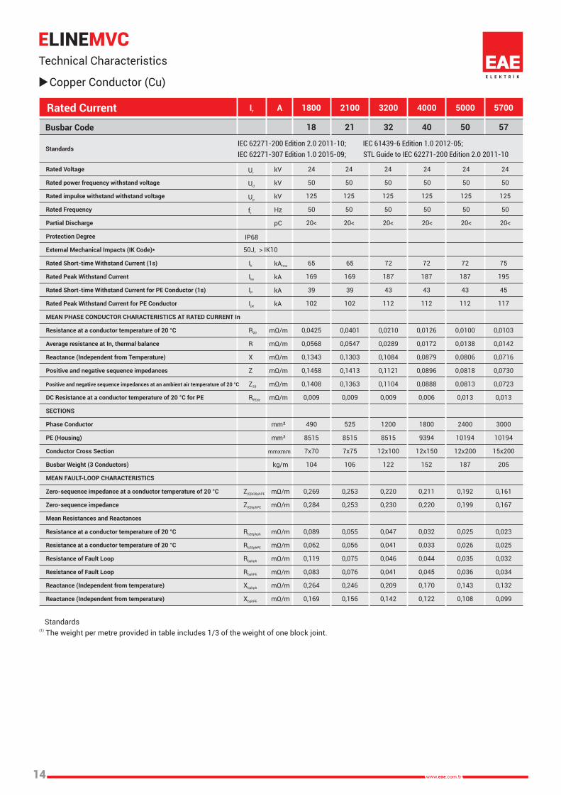
(1) The weight per metre provided in table includes 1/3 of the weight of one block joint.
Standards
Copper Conductor (Cu)
Technical Characteristics
E MVCLINE
14
Busbar Code
Rated Current Ir A 5700
50 57
1800
21
2100 4000
32
Ur
Ud
Up
fr
IP68
50J, > IK10
Ik
Ike
IP
Ipe
R20
R
X
Z
Z20
RPEdc
Z(0)b20phPE
Z(0)bphPE
Rb20phph
Rb20phPE
Rbphph
RbphPE
Xbphph
XbphPE
kV
kV
kV
Hz
pC
kArms
kA
kA
kA
mΩ/m
mΩ/m
mΩ/m
mΩ/m
mΩ/m
mΩ/m
mm²
mm²
mmxmm
kg/m
mΩ/m
mΩ/m
mΩ/m
mΩ/m
mΩ/m
mΩ/m
mΩ/m
mΩ/m
3200
40
IEC 62271-200 Edition 2.0 2011-10; IEC 61439-6 Edition 1.0 2012-05;
IEC 62271-307 Edition 1.0 2015-09; STL Guide to IEC 62271-200 Edition 2.0 2011-10Standards
Rated Voltage
Rated power frequency withstand voltage
Rated impulse withstand withstand voltage
Rated Frequency
Partial Discharge
Protection Degree
External Mechanical Impacts (IK Code)*
Rated Short-time Withstand Current (1s)
Rated Peak Withstand Current
Rated Short-time Withstand Current for PE Conductor (1s)
Rated Peak Withstand Current for PE Conductor
MEAN PHASE CONDUCTOR CHARACTERISTICS AT RATED CURRENT In
Resistance at a conductor temperature of 20 °C
Average resistance at In, thermal balance
Reactance (Independent from Temperature)
Positive and negative sequence impedances
Positive and negative sequence impedances at an ambient air temperature of 20 °C
DC Resistance at a conductor temperature of 20 °C for PE
SECTIONS
Phase Conductor
PE (Housing)
Conductor Cross Section
Busbar Weight (3 Conductors)
MEAN FAULT-LOOP CHARACTERISTICS
Zero-sequence impedance at a conductor temperature of 20 °C
Zero-sequence impedance
Mean Resistances and Reactances
Resistance at a conductor temperature of 20 °C
Resistance at a conductor temperature of 20 °C
Resistance of Fault Loop
Resistance of Fault Loop
Reactance (Independent from temperature)
Reactance (Independent from temperature)
5000
18
24
50
125
50
20<
24
50
125
50
20<
24
50
125
50
20<
24
50
125
50
20<
24
50
125
50
20<
65
169
39
102
0,0401
0,0547
0,1303
0,1413
0,1363
0,009
525
8515
7x75
106
0,253
0,253
0,055
0,056
0,075
0,076
0,246
0,156
24
50
125
50
20<
65
169
39
102
0,0425
0,0568
0,1343
0,1458
0,1408
0,009
490
8515
7x70
104
0,269
0,284
0,089
0,062
0,119
0,083
0,264
0,169
72
187
43
112
0,0210
0,0289
0,1084
0,1121
0,1104
0,009
1200
8515
12x100
122
0,220
0,230
0,047
0,041
0,046
0,041
0,209
0,142
72
187
43
112
0,0126
0,0172
0,0879
0,0896
0,0888
0,006
1800
9394
12x150
152
0,211
0,220
0,032
0,033
0,044
0,045
0,170
0,122
72
187
43
112
0,0100
0,0138
0,0806
0,0818
0,0813
0,013
2400
10194
12x200
187
0,192
0,199
0,025
0,026
0,035
0,036
0,143
0,108
75
195
45
117
0,0103
0,0142
0,0716
0,0730
0,0723
0,013
3000
10194
15x200
205
0,161
0,167
0,023
0,025
0,032
0,034
0,132
0,099

24
kV
3000 mm
L1 L2 L3
Standard FeederStraight Length
- STD
Sample Order:
24 kV 1800 A, Copper,Feeder, IP 68, 3 Conductors
MVC 2418 - STD
- XSpecial Feeder Straight Length
1000 mm
Sample Order:
24 kV 3200 A, Copper, Feeder, IP 68,3 Conductors, 1500 mm Special Length
MVC 2432 - X - 150
Information:
Feeder MinimumSpecial length size = 1000 mm
L1 L2 L3
Busbar Code
MVA - Al
Conductor1500 2000
15 20
A 160 160mm
Table For Outer Dimension of Busbars
MVC - Cu
Conductor
Busbar Code
Rated Current(A)
7X75 12X100
160 210 260
1800 2100 3200 4000 5000
2500 3000
12X150 12X200 -
25 30
-
-
18 21 32 40 50
7X75 12X100 12X150 12X2007X70
5700
57
15X200
260
Standard Straight Length
E MVLINE
15
Rated Current(A)
ConductorCross
Section
ConductorCross Section
ConductorCross Section
A
578
B
B mm 247 247 247 297 347 347

Sample Order:
24 kV 2100 A, Copper, Feeder, IP 68, 3 Conductors
MVC 2421 - U
Upwards Downwards Elbow - U- D
Sample Order:
24 kV 3200 A, Copper, Feeder, IP 68, 3 Conductors
MVC 2432 - R
Left Right Elbow - R- L
Panel Connection - P10- T10 Sample Order:
24 kV 5000 A, Copper, Feeder, IP 68, 3 ConductorsFor Panel Feeder
MVC 2450 - P10
R
S
T
L1 L2 L3
L1
L2
L3
62
5 m
m3
45
mm
970 mm
10
10
mm
13
0
mm
Elbows
E MVLINE
16
Rated Current(A)
Busbar Code
MVA - Al
Conductor1500 2000
15 20
X 690 690mm
Table of Busbar Cross Section Sizes
MVC - Cu
Conductor
Busbar Code
Rated Current(A)
7X75 12X100
690 740 790
1800 2100 3200 4000 5000
2500 3000
12X150 12X200 -
25 30
-
-
18 21 32 40 50
7X75 12X100 12X150 12X2007X70
5700
57
15X200
790
10
40
mm
1040 mm
X
X
ConductorCross Section
ConductorCross Section

24
kV
1 2
3 4
5 6
7 8
The ends of the conductors of the busbars are cleaned with a clean dry cloth. The busbars have to be fixed in the same axis, with a max. distance of 10 mm between the two conductors.
As shown on the figure, junction plates shall be fixed as the bolts face the same direction at all times.
All bolts must be tightened to 72 Nm with torque wrench. Before the casting moulds assembling, inner surfaces of casting mouldshave to wiped with clean dry cloth.
The mixture prepared for casting should be cast from the same spot at all times.
The material should be 'vibrated' with the help of a plastic hammer to remove the air in the material. Then the air bubbles on the surface have to brushed.
After the curing of the cast material is complete the sheet metal moulds can be removed. ( Reaction is completed within 8 - 24 hours based on the air temperature. )The flexibles are fitted to the profiles grooves for earth continuity.
24 kV Medium Voltage Busbar Horizontal Application
E MVLINE
17
Joint protection pieces of perforated aluminium should be fitted.

1 2
3 4
5 6
7
24 kV Medium Voltage Busbar Vertical Application
E MVLINE
18
8
The ends of the conductors of the be busbars are cleaned witha clean dry cloth. The busbars have to fixed in the sameaxis, with a max. distance of 10 mm between thetwo conductors.
As shown on the figure, junction plates shall be fixed as the bolts face the same direction at all times.
All bolts must be tightened to 72 Nm with torque wrench. Support sheets are secured on the lower part of juncture area by stem bar. A min. 50-60 mm. The joint moulds are affixed on the support sheet by cleaning with a dry and clean piece of cloth.
The prepared for casting should be cast from the same spot at all times.
The material should be 'vibrated' with the help of a plastic hammer to remove the air in thematerial. Then the air bubbles on the surface have to brushed.
After the curing of the cast material is complete the sheet metal moulds can be removed.( Reaction is completed within 8 - 24 hours based on the air temperature. )The flexibles are fitted to the profiles grooves for earth continuity.
Joint protection pieces of perforated aluminium should be fitted.

24
kV
Electrical Values
- Nominal insulation voltage of 24kV busbartrunking system should be 50kV.
- For the tin coated aluminum or copper, the environmentaltemperature should be maximum 40 °C while the maximumtemperature rise should be 90 K.
- Minimum short circuit busbar lengthsshould be as follows.
Protection Class
- Busbar installations shall have the protection class of IP 68.
1-
2-
2.1-
2.2-
2.3-
2.4-
2.5-
2.6-
3-
1500A TO 5700 A MEDIUM VOLTAGE BUSBAR SYSTEMS (E- LINE MV)GENERAL PRODUCT SPECIFICATIONS
Standards & Certification:- Busbar trunking system shall be designed in accordance with international standards IEC 62271-200 and IEC 61439-6, type tests thereof shall be conducted and manufactured in accordance with the standard. Type tests shall be conducted by independent and accredited testing and certification bodies with international validity and certified accordingly. Short-circuit type tests and the following 3 main type tests shall be conducted for each current rating of busbar system and conformity certificate for the standards shall be obtained.
Modular Joint Structure The phase conductors shall be joined using two junction plates per phase of suitable cross section to maintain the rating integrity of the conductors. These plates shall be secured using bolts with non-sharp tips torqued to 72 Nm. The joint shall be completed using a mixture of epoxy and silicon to match the material of the busbar lengths. This material should be compliant with temperature changes and thermal expansion. It should ensure high protection against external impacts. Juncture point bolts should be tightened with torque wrench set to 72 Nm (55 lbft)
Insulation Structure- Bars with high conductivity value should be insulated with a special composite material composed of allot of specially selected sand, calcite and epoxy resin. This material should be compliant with temperature changes and thermal expansion. It should ensure high protection against external impacts.
Assembly and Commissioning Tests- The assembly of the busbar trunking system should be performed in accordance with the electrical project , electrical single line diagram, layout plans and detailed busbar application projects in line with the type and current values indicated on these plans, instructions provided by the manufacturer should be strictly abided with during the assembly process. Joint bolts shall definitely be tightened by the torque wrench set to correct values and insulated accordingly. - Upon the completion of the assembly of the busbar system and controlling of the compliance to the project thereof and assembly instructions;
a) Di-Electric test with very low frequency should be conducted.b) Joint resistances and Line resistances should be measured.c) Phase sequences should be checked.
Housing and Overall Structure- Housing of busbar lengths is a special design and should be manufactured from a cast material.- The structure of the busbar lengths shall have tin plated conductors along their complete length within the housing.- In the busbar trunking system, there should be down-up and right-left turning elements, panel, transformer and cable connection elements, closure, horizontal and vertical expansion elements as a standard. Special modules and special size busbar lengths that may be required during the implementation of the project should be able to be manufactured within a short time and in accordance with the standard specification and technique. - If busbar runs pass through the building expansion joint a horizontal expansion element shall be used in the run. In addition horizontal expansion elements should be used at each 40 m on the horizontal lines.
Overall System StructureBusbar system should be with low impedance complying with the following specifications. This should be accomplished by placement of the tin coated conductors within the material with no entrapped air within.
Conductors and Phase Configuration- Busbar trunking system should be aluminum conductive between 1500-3000A.- Busbar trunking system should be copper conductive between 1800-5700A.- Busbar trunking systems conductors shall be high conductivity copper with .
a) 3 Conductors / PE housing
- Aluminum conductors must be in the EC-Grade class. The minimum conductivity must be 34 m/mm².... . Entire surfaces of the aluminum conductors should be tin-coated.- Copper conductors should be 99.99% electrolytic copper. Minimum conductivity value should be 56 m/mm². Entire surfaces of the electrolytic copper conductors should be tin-coated.
For Al Conductors;
For Cu Conductors;1800-2100 A : phase-phase 1 sec. value 65 kA, peak value 169 kA3200-5700 A : phase-phase 1 sec. value 72 kA, peak value 187 kA
General Product Specifications
E MVLINE
19
1500 A : phase-phase 1 sec. value 50 kA, peak value 130 kA2000-3000 A : phase-phase 1 sec. value 72 kA, peak value 187 kA

20
Project Design Form
E MVLINEQ
uantit
yC
om
po
nen
t
Co
mp
on
en
t Lis
t
Item
Nam
e :
Date
:
Sig
natu
re :
Prepared by
Co
mp
an
y :
Pro
ject
:
Pro
ject
No
:
Ple
ase
du
plic
ate
th
is p
ag
e fo
r yo
ur
ow
n u
se.

PRODUCT TYPES
BUSBAR ENERGY DISTRIBUTION SYSTEMS
CABLE TRAYS
TROLLEY BUSBAR ENERGY DISTRIBUTION SYSTEMS
INDOOR SOLUTIONS
SUPPORT SYSTEMS
Please visit our website for the updated version of our catalogues.www.eae.com.tr
GERMANYAUSTRIA
AZERBAIJANBAHRAIN
BANGLADESH
BELARUS
BELGIUM
BRASIL
BULGARIA
U.KINGDOM
U. A. EMIRATES
ALGERIA CHINA
CZECH REP.
DENMARK
EQ. GUINEA
ESTONIA
ETHIOPIA
MOROCCO
FRANCE
FINLAND
GHANA
SOUTH KOREA
SOUTH AFRICA
CROATIA
INDIA
NETHERLANDS IRAQIRELAND SPAIN
SWITZERLANDITALY
ICELAND
CAMEROONQATAR
KAZAKHSTAN
KENYA
CYPRUS
KONGOKUWAIT
LATVIALIBYA
LITHUANIA
LEBANON
LUXEMBOURGHUNGARY
MADAGASKAR
MACEDONIAMALTA
EGYPTMAURITIUS
MYANMAR
NIGERIA
NORWAY
PAKISTANPERU
POLAND
ROMANIA
RUSSIA
RWANDASLOVENIA
SERBIA
SINGAPORE
SRI LANKA
SAUDI ARABIA
SUDAN
SYRIA
CHILE
TANZANIA
THAILAND
TAIWAN
TUNISIA
TURKMENISTAN
UKRAINE
OMANVIETNAM
YEMEN
GREECEAZERBAIJAN
OMAN
TURKEY
PAKISTAN
BELGIUMNETHERLANDSPOLAND
NETHERLANDS
BELGIUM
NORWAYSWITZERLANDVIETNAM
NIGERIA
KENYA
OMAN
YEMENOMAN
ETHIOPIA
TURKMENISTANTURKMENISTAN
SERBIASINGAPORE
U. A. EMIRATES
SUDAN
TANZANIA
CHILE
VIETNAMTURKMENISTAN
MADAGASKARSPAIN
U. A. EMIRATES
CAMEROONTHAILAND
CHILE
TURKMENISTAN
KUWAITSYRIA
ETHIOPIA
MADAGASKARTANZANIA
FRANCE
CAMEROON
SYRIA
U. A. EMIRATES
KENYA
LUXEMBOURG
FRANCE
UZBEKISTAN
PERUCHILESUDANOMANIRAQ
MADAGASKARLATVIA
QATAR
THAILAND
TURKEY
TURKEY
TURKEYTURKEY
TURKMENISTANMACEDONIA
IRELANDVIETNAMGHANA
CZECH REP.
BELGIUMU. A. EMIRATESSINGAPOREAZERBAIJAN
GREECE
SPAIN
U.KINGDOMCROATIA
NIGERIAQATAR
AUSTRIA
YEMEN SWITZERLANDSUDAN
RUSSIA
SOUTH KOREA
SYRIA
CAMEROON
GHANA
MYANMAR
NIGERIA
PERU
EGYPT VIETNAM
YEMEN
POLAND
VIETNAM
BULGARIA
TANZANIADENMARK
GREECE
VIETNAM
PAKISTANDENMARK
TAIWAN
MACEDONIA
AZERBAIJANSWITZERLAND
QATAR
SRI LANKANIGERIA
TURKEYPERU
SYRIAUZBEKISTAN
BULGARIA
NETHERLANDS
U. A. EMIRATES
GHANA
YEMENKAZAKHSTAN
GREECE
ESTONIAQATAR
BELGIUMAZERBAIJAN
SWITZERLAND
GHANA MADAGASKAR
MACEDONIA
SUDAN
YEMENDENMARKMADAGASKARROMANIA
RUSSIA CHINA
MYANMAR
SOUTH KOREAYEMEN
KAZAKHSTAN QATARVIETNAM
VIETNAM
UZBEKISTAN FINLANDSLOVENIA
KOREA
KAZAKHSTAN CAMEROONSLOVENIA
GREECE
ALGERIA

NTAL E MM AN NO AR GI EV MNE E ND TN SA YY STI TL EA M
U SQ
ISO 90011400127001
EAE Elektrik A.S.Akcaburgaz Mahallesi,
3114. Sokak, No:10 34522Esenyurt - Istanbul - TURKEY
Tel: +90 (212) 866 20 00Fax: +90 (212) 886 24 20
IEC 61439-6 T Es
Catalogues 35-ENG. / Rev 00 1.000 pcs 18/07/2018F.A
EAE has full right to make any revisions or changes on this catalogue without any prior notice.
E 344805
Please visit our website for the updated version of our catalogues.www.eae.com.tr/EN