e family - versa products
TRANSCRIPT

1
Versa Products Company, Inc., 22 Spring Valley Rd., Paramus, NJ 07652 USA Phone: (201)-843-2400 Fax: (201)-843-2931Versa BV, Prins Willem Alexanderlaan 1427, 7312 GB Apeldoorn, The Netherlands Phone: +31-55-368-1900 Fax: +31-55-368-1909
E-mail: [email protected] www.versa-valves.com
E FAMILY
Bulletin E2019
Reviewed Dec. 2021

Page 8-10 Page 11-13 Page 14-17 Page 18-21 Page 22 Page 23
Series EZ E5 E4 E E3 E* QE
DescriptionCompact
Direct ActingCompact
Direct ActingCompact
Direct ActingMedium FlowDirect Acting
High FlowDirect Lift
High Flow
Pressure Range
vacuum to 250 psi (17 bar)
vacuum to 500 psi (34 bar)
vacuum to 500 psi (34 bar)
vacuum to 500 psi (34 bar)
0-150 psi(10.3 bar)
5-150 psi(0.3-10.3 bar)
Flow Range 0.022 to 0.26 Cv 0.022 to 0.26 Cv 0.022 to 0.26 Cv 0.022 to 0.79 Cv 0.06 to 0.16 Cv Inlet 0.022 to 0.21 CvExhaust 3.3 to 8.8 Cv
Port Size NPT 1/8” NPT 1/8” - 1/4” NPT 1/8” - 1/4” NPT 1/8” - 1/4” NPT 1/4” NPT 1/4”-1/2” NPT Inlet3/8”- 3/4” NPT Exhaust
Nominal Power10 AC watt
10.5 DC watt6 - 8.5 AC watt7-10 DC watt 0.85 - 1.8 watt 6 - 8.5 AC watt
7-10 DC watt 0.85 - 1.8 watt 0.85 - 7.2 Watt
SealsNBR-Nitrile (Buna N)
FKM (fluorocarbon) OptionalFKM
(fluorocarbon)NBR-Nitrile
(Buna N) FKM (fluorocarbon)
Materials, General Purpose
SidePort
Aluminum Page 10 — — — — —
Stainless Steel — Page 11 — Page 18 — Page 23
ManifoldMount
Aluminum Page 12 — — Page 20 — —
Stainless SteelConsult Factory
— —Consult Factory
— —
Materials, Hazardous Location
SidePort
Aluminum — — — — — —
Stainless Steel — Page 13 Page 14 - 17 Page 18 Page 22 Page 23
ManifoldMount
Aluminum Page 10 — — Page 20 — —
— — — —Consult Factory
— —
Series Body Code Orifice Options VoltageE5SM 3 2 0 1 3 4 H2 A120
E5SM Series Solenoid, Spring Return
ThreeWay
1/8” NPT
Side Ports
NCBottom Top Solenoid
exhaustadapter
120V60COILOrifice Size
Orifice/CvCode Orifice Cv
23468101216
1/32” 3/64” 1/16” 3/32”1/8”5/32”3/16”1/4”
0.022 0.06 0.11 0.21 0.26 0.45 0.56 0.79
2 www.versa-valves.com
QUICK INDEX
112019
Basic Part Number Code
Solenoid options - Non Hazardous Location .............................................................................................Page 4
Solenoid options - Hazardous Locations ....................................................................................................Page 6
Solenoid - Cross Reference Chart ..............................................................................................................Page 5
Basic Features ..............................................................................................................................................Page 3
Valve Types — Series ................................................................................................................... See Chart Below

3www.versa-valves.com
Versa’s E-Series valves are 2 port, 2 position and 3 port, 2 position direct acting pneumatic and hydraulic valves consisting of two body types, side ported and manifold mounted.
E Series Side-Ported valves are individually mounted with body port sizes 1/8” NPT to 1/4” NPT.
Manifold Mounting valve is direct solenoid actuated and is mounted on a manifold which can have 1 to 10 valve stations. The manifolds are provided with the threaded ports for pipe connections, which allows the valves to be easily and swiftly installed or removed without breaking any pipe connections. The manifolds also provide common ports, such as the inlet and exhaust, making only one such connection necessary per manifold.
High Performance SolenoidNear frictionless direct acting poppet deign yields positive shifting, the lowest wattage ratings and unsurpassed reliability. Life cycle ratings to 20 million cycles.
Design for Reliability, Flexibility and Availability
The E Family
Direct Acting Solenoid Design The E Family of solenoid valves utilize a high performance solenoid direct acting for the perfect balance of flow vs. power. Valves designed for complete pressure range including vacuum.
Bubble Tight SealingThe E Family of products utilizes an elastomer sealed poppet. This design offers a bubble tight seal. Many seal materials are available to offer the greatest flexibility is application/media solutions.
Durable Materials of ConstructionE Family materials are available in stainless steel or aluminum to offer the greatest flexibility in application/media solutions.
Porting OptionsE Family valves are available with 1⁄8 ” or ¼” ports for ease of installation. Select Families are available in manifolded configurations for ease of installation, space savings and trouble free maintenance.
Vent OptionsThe standard E Family valve is offered with a threaded vent port. This supports piped ex-haust for gases and hydraulic applications. Other vent options are offered to keep con-taminates out of the valve for long trouble, free service.
High Heat Epoxy Molded CoilsThe E Family solenoid’s are high heat rated and are all epoxy molded. A Versa standard! The epoxy molded coil yield a moisture resistance design which also dissipates heat for elevated temperature applications.
Electrical ConnectionsThe E Family of solenoid valves offer the widest range of electrical hook connections, from ½” conduit to spade terminals and everything in between. All designed to simplify installation and serviceability. Select E Family valves are offered for hazardous location service, should application require such.
BASIC FEATURES

SeriesSuffix Detail
Certification- (Conformance) Ingress
ProtectionVoltage (Power)
Electrical Characteristics Miscellaneous
AC DC
E5SM Standard-PC CSA NEMA
1, 2, 3 & 424V60, 120V60, 240V60 (8W) 24V50, 110V50, 220V50 (8W) 12VDC, 24VDC, 48VDC (7W)
Class F epoxy molded coil
(155ºC). Continuous duty.
Steel cover with 1/2 NPT conduit entry.
ESM Standard-PC
CSA, UL
NEMA 4;IP65
24V60, 120V60, 240V60 (7.3W) 24V50, 110V50, 220V50 (7.3W) 12VDC, 24VDC, 48VDC (9.5W)
EZE5SM -228L NEMA 4
24V60, 120V60, 240V60 (8.5W) 24V50, 110V50, 220V50 (8.5W) 12VDC, 24VDC, 48VDC (10.5W
Epoxy molded coil with integral 1/2” npt conduit hub
E5SM
-243
NEMA1, 2 & 3
24V60, 120V60, 240V60 (8W) 24V50, 110V50, 220V50 (8W) 12VDC, 24VDC, 48VDC (7W)
Steel cover with grommited (flying) leads. 2 leads 24” (60 cm)
ESM NEMA1, 2 & 3
24V60, 120V60, 240V60 (7.3W) 24V50, 110V50, 220V50 (7.3W) 12VDC, 24VDC, 48VDC (9.5W)
Steel cover with grommited (flying) leads 2 leads 24” (60 cm)
EZ — NEMA1, 2 & 3
24V60, 120V60, 240V60 (8.5W) 24V50, 110V50, 220V50 (8.5W) 12VDC, 24VDC, 48VDC (10.5W)
flying leads. 2 leads 24” (60 cm)
EZE5SM
-HC
CSA, UL NEMA 424V60, 120V60, 240V60 (8.5W) 24V50, 110V50, 220V50 (8.5W) 12VDC, 24VDC, 48VDC (10.5W)
Spade terminals (3). Connector: mini DIN socket with PG9 cable gland.
ESM — IP 6524V60, 120V60, 240V60 (12W) 24V50, 110V50, 220V50 (12W) 12VDC, 24VDC, 48VDC (10W)
Spade terminals (3) Connector pins according to Din 43650 & ISO 4400
EZE5SM
-HCL
CSA, UL
NEMA 424V60, 120V60, 240V60 (8.5W) 24V50, 110V50, 220V50 (8.5W) 12VDC, 24VDC, 48VDC (10.5W)
Spade terminals (3). Connector: mini DIN socket with PG9 cable gland.
ESM IP 6524V60, 120V60, 240V60 (12W) 24V50, 110V50, 220V50 (12W) 12VDC, 24VDC, 48VDC (10W)
Spade terminals (3) Connector pins according to Din 43650 & ISO 4400
EZE5SM
-HCC
NEMA 424V60, 120V60, 240V60 (8.5W) 24V50, 110V50, 220V50 (8.5W) 12VDC, 24VDC, 48VDC (10.5W)
Spade terminals (3). Connector: mini DIN socket with PG9 cable gland.
ESM — IP 6524V60, 120V60, 240V60 (12W) 24V50, 110V50, 220V50 (12W) 12VDC, 24VDC, 48VDC (10W)
Spade terminals (3) Connector pins according to Din 43650 & ISO 4400
EZE5SM
-HCCL
CSA, UL NEMA 424V60, 120V60, 240V60 (8.5W) 24V50, 110V50, 220V50 (8.5W) 12VDC, 24VDC, 48VDC (10.5W)
Spade terminals (3). Connector: mini DIN socket with PG9 cable gland.
ESM — IP65
24V60, 120V60, 240V60 (12W) 24V50, 110V50, 220V50 (12W) 12VDC, 24VDC, 48VDC (10W)
Spade terminals (3) Connector pins according to Din 43650 & ISO 4400
ESM -P — NEMA 4;IP65
Steel cover with electrical plug-in. A Solenoid which can be removed from subplate or manifold, without disturbing the wiring
4 www.versa-valves.com
NONHAZARDOUS LOCATION SOLENOIDS SOLENOID SELECTOR General Purpose

Recommended Hazardous LocationSolenoid Option Packages
Certification/Power
North American - CSA ATEX - IECEx - INMETRO
Series Enclosure/Wire Standard Power Low Watt* Standard Power Low Watt*
E Steel, Electroless Nickel Plated, 24 Inch Leads -XXL4 n/a n/a n/a
E5Steel, Electroless Nickel Plated, 24 Inch Leads -XXL4 XXN4 -XNL4 -XNN4
Stainless Steel, 24” wire leads -XXE4 n/a -XNE4 n/a
E4Stainless Steel, High Performance 430 type, 24” wire leads n/a -XV9 n/a -XT9**
Stainless Steel, 316L type, Junction Box with Terminal Strip n/a -XDBT9** n/a -XDBS9**
North American (-XX)Combination
Suffix Included Suffix
-XXA -XX, -HT-XXA4 -XX, -D14, -HT-XXB -XX, -PS-XXB4 -XX, -D14, -PS-XXC -XX, -HT, -PS-XXC4 -XX, -D14, -HT, -PS-XXD -XX, -ST-XXD4 -XX, -D14, -ST-XXE -XX, -PC, -ST-XXE4 -XX, -D14, -PC, -ST-XXF -XX, -HT, -ST-XXF4 -XX, -D14, -HT, -ST-XXG -XX, -LB, -ST-XXG4 -XX, -D14, -LB, -ST-XXH -XX, -HT, -PC, -ST-XXH4 -XX, -D14, -HT, -PC, -ST-XXJ -XX, -LB, -PC, -ST-XXJ4 -XX, -D14, -LB, -PC, -ST
World Solenoid (-XDB, -XT, -XV)Combination Suffix
Included Suffix1.8 Watt 0.85 Watt-XDBS1 -XDBS1C -XDBS, -HT, -LX-XDBS2 -XDBS2C -XDBS, -HT, -LX, -H2E-XDBS3 -XDBS3C -XDBS, -HT, -LX, -HE-XDBS4 -XDBS4C -XDBS, -HT, -LX, -L14-XDBS5 -XDBS5C -XDBS, -HT, -LX, -303D-XDBS6 -XDBS6C -XDBS, -HT, -LX, -H2E, -303D-XDBS7 -XDBS7C -XDBS, -HT, -LX, -HE, -303D-XDBS8 -XDBS8C -XDBS, -HT, -LX, -L14, -303D-XDBS9 -XDBS9C -XDBS, -HT, -LX, -D14-XDBS10 -XDBS10C -XDBS,-HT,-LX,-D14, -303D-XDBT1 -XDBT1C -XDBT, -HT, -LX-XDBT2 -XDBT2C -XDBT, -HT, -LX, -H2E-XDBT3 -XDBT3C -XDBT, -HT, -LX, -HE-XDBT4 -XDBT4C -XDBT, -HT, -LX, -L14-XDBT5 -XDBT5C -XDBT, -HT, -LX, -303D-XDBT6 -XDBT6C -XDBT, -HT, -LX, -H2E, -303D-XDBT7 -XDBT7C -XDBT, -HT, -LX, -HE, -303D-XDBT8 -XDBT8C -XDBT, -HT, -LX, -L14, -303D-XDBT9 -XDBT9C -XDBT, -HT, -LX, -D14-XDBT10 -XDBT10C -XDBT, -HT, -LX, -D14, -303D-XV1 -XV1C -XV, -HT, -LX-XV2 -XV2C -XV, -HT, -LX, -H2E-XV3 -XV3C -XV, -HT, -LX, -HE-XV4 -XV4C -XV, -HT, -LX, -L14-XV9 -XV9C -XV, -HT, -LX, -D14-XT1 -XT1C -XT, -HT, -LX-XT2 -XT2C -XT, -HT, -LX, -H2E-XT3 -XT3C -XT, -HT, -LX, -HE-XT4 -XT4C -XT, -HT, -LX, -L14-XT9 -XT9C -XT -HT, -LX, -D14
ATEX (-XN)Combination
Suffix Included Suffix
-XNA -XN, -HT-XND -XN, -ST-XNE -XN, -PC, -ST-XNE4 -XN, D14, -PC, -ST-XNF -XN, -HT, -ST-XNG -XN, -LB, -ST-XNH -XN-HT, -PC, -ST-XNJ -XN, -LB, -PC, -ST-XNJ4 -XN, -D14, -LB, -PC, -ST-XNK -XN, -HT, -LB, -PC, -ST-XNL -XN, -PC-XNL4 -XN, -D14, -PC-XNM -XN, -HT, -PC-XNN -XN, -LB, -PC-XNN4 -XN, -D14, -LB, -PC-XNP -XN, -HT, -LB, -PC
ATEX (-XN) (Cont.)Combination
Suffix Included Suffix
-XNQ -XN, -HT, -LB-XNR -XN, -LB-XNS -XN, -LA, -ST-XNU -XN, -HT, -LB, -ST-XNV -XN, -LA-XNX -XN, -LB, -PS-XNWS -XN, -VJBT, -LB, -PS
North American (-XX) (Cont.)Combination
Suffix Included Suffix
-XXK -XX, -HT, -LB, -PC, -ST-XXK4 -XX, -D14, -HT, -LB, -PC, -ST-XXL -XX, -PC-XXL4 -XX, -D14, -PC-XXM -XX, -HT, -PC-XXM4 -XX, -D14, -HT, -PC-XXN -XX, -LB, -PC-XXN4 -XX, -D14, -LB, -PC-XXP -XX, -HT, -LB, -PC-XXP4 -XX, -D14, -HT, -LB, -PC-XXQ -XX, -HT, -LB-XXQ4 -XX, -D14, -HT, -LB-XXR -XX, -LB-XXR4 -XX, -D14, -LB-XXS -XX, -LA, -ST-XXS4 -XX, -D14, -LA, -ST-XXU -XX, -HT, -LB, -ST-XXU4 -XX, -D14, -HT, -LB, -ST-XXV -XX, -LA-XXV4 -XX, -D14, -LA-XXW -XX, -CD, -HT, -H2, -PC, -ST-XXW4 -XX, -D14, -CD, -HT, -PC, -ST
Suffix ReferenceSuffix Description
-CD 72” wire leads-D14 Solenoid vent, water proof nut-H2E 1/8” npt Solenoid vent-HE ¼” npt Solenoid vent-HT Class H coil-L14 Solenoid vent dust nut-LA 0.85 watt Solenoid-LB 1.8 watt Solenoid-LV 0.85 watt (World Solenoid)-LX 1.8 watt (World Solenoid)-LZ 0.5 watt (World Solenoid)-PC Potted coil, NEMA 4-PS Potted coil, male conduit; -ST Stainless Solenoid housing-XDBS World Solenoid**-XDBT World Solenoid**-VJBT Add on Junction Box-XN ATEX Solenoid-XT World Solenoid** -XV World Solenoid, North America-XX North American Solenoid-303D Integral diode
5www.versa-valves.com
HAZARDOUS LOCATION
Cross Reference Chart (E, E4 & E5)Combination Suffix Details
*1.8 watt solenoid. Also available is 0.85 watt, see cross reference chart above, 1.8 & 0.85 not available on E. For 0.50 watt, consult factory.**All the –XDBS, -XDBT & -XT solenoids are “World Solenoids” certified for North America, ATEX, IECEx and INMETRO. For additional certifications consult factory. -XV solenoids certified for North America.
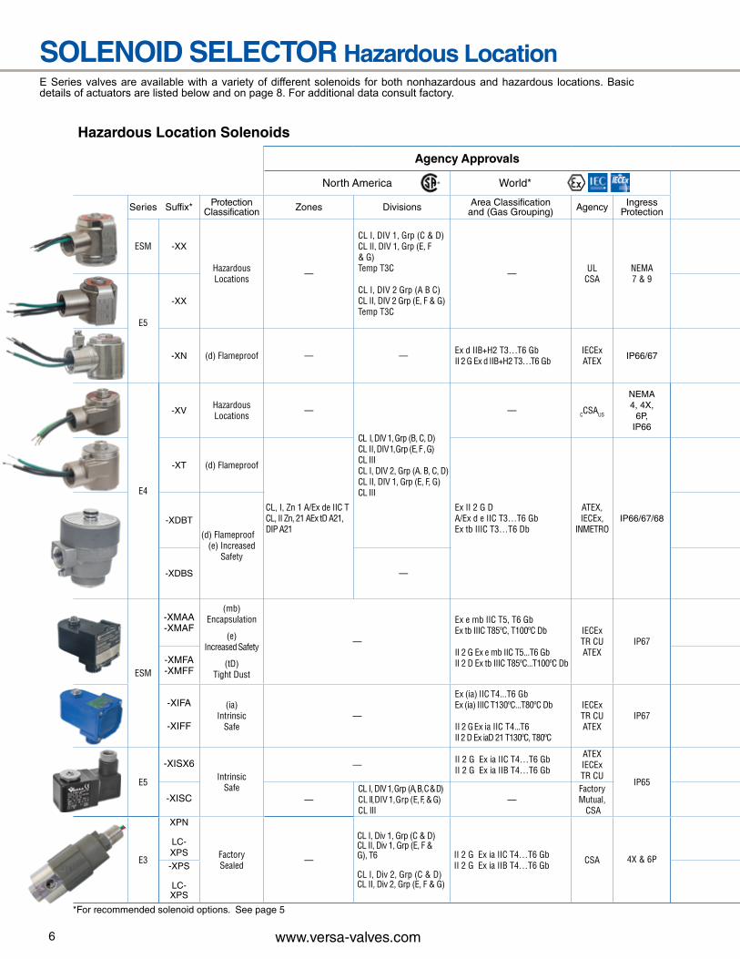
Hazardous Location Solenoids
Agency Approvals
North America World*
Series Suffix* Protection Classification Zones Divisions Area Classification
and (Gas Grouping) Agency IngressProtection
ESM -XX
Hazardous Locations —
CL I, DIV 1, Grp (C & D)CL II, DIV 1, Grp (E, F & G)Temp T3C
CL I, DIV 2 Grp (A B C)CL II, DIV 2 Grp (E, F & G)Temp T3C
— ULCSA
NEMA7 & 9
E5
-XX
-XN (d) Flameproof — — Ex d IIB+H2 T3…T6 GbII 2 G Ex d IIB+H2 T3…T6 Gb
IECExATEX IP66/67
E4
-XVHazardous Locations —
CL I, DIV 1, Grp (B, C, D)CL II, DIV 1, Grp (E, F , G)CL III CL I, DIV 2, Grp (A. B, C, D)CL II, DIV 1, Grp (E, F, G)CL III
— CCSAUS
NEMA4, 4X,
6P, IP66
-XT (d) Flameproof
CL, I, Zn 1 A/Ex de IIC TCL, II Zn, 21 AEx tD A21,DIP A21
Ex II 2 G D A/Ex d e IIC T3…T6 Gb Ex tb IIIC T3…T6 Db
ATEX,IECEx,
INMETROIP66/67/68-XDBT
(d) Flameproof(e) Increased
Safety
-XDBS —
ESM
-XMAA -XMAF
(mb) Encapsulation
(e)Increased Safety
(tD)Tight Dust
—
Ex e mb IIC T5, T6 GbEx tb IIIC T85ºC, T100ºC Db
II 2 G Ex e mb IIC T5...T6 GbII 2 D Ex tb IIIC T85ºC...T100ºC Db
IECExTR CUATEX
IP67
-XMFA-XMFF
-XIFA
-XIFF
(ia)Intrinsic
Safe—
Ex (ia) IIC T4...T6 GbEx (ia) IIIC T130ºC...T80ºC Db
II 2 G Ex ia IIC T4...T6II 2 D Ex iaD 21 T130ºC, T80ºC
IECExTR CUATEX
IP67
E5
-XISX6Intrinsic
Safe
— II 2 G Ex ia IIC T4…T6 GbII 2 G Ex ia IIB T4…T6 Gb
ATEXIECExTR CU
IP65
-XISC —CL I, DIV 1, Grp (A, B, C & D) CL II, DIV 1, Grp (E, F, & G) CL III
—Factory Mutual,
CSA
E3
XPN
LC-XPS Factory
Sealed —
CL I, Div 1, Grp (C & D)CL II, Div 1, Grp (E, F & G), T6
CL I, Div 2, Grp (C & D)CL II, Div 2, Grp (E, F & G)
II 2 G Ex ia IIC T4…T6 GbII 2 G Ex ia IIB T4…T6 Gb CSA 4X & 6P
-XPS
LC-XPS
6 www.versa-valves.com
SOLENOID SELECTOR Hazardous LocationE Series valves are available with a variety of different solenoids for both nonhazardous and hazardous locations. Basic details of actuators are listed below and on page 8. For additional data consult factory.
*For recommended solenoid options. See page 5
Hazardous Location Solenoids
Agency Approvals
North America World*
Series Suffix* Protection Classification Zones Divisions Area Classification
and (Gas Grouping) Agency IngressProtection
ESM -XX
Hazardous Locations —
CL I, DIV 1, Grp (C & D)CL II, DIV 1, Grp (E, F & G)Temp T3C
CL I, DIV 2 Grp (A B C)CL II, DIV 2 Grp (E, F & G)Temp T3C
— ULCSA
NEMA7 & 9
E5
-XX
-XN (d) Flameproof — — Ex d IIB+H2 T3…T6 GbII 2 G Ex d IIB+H2 T3…T6 Gb
IECExATEX IP66/67
E4
-XVHazardous Locations —
CL I, DIV 1, Grp (B, C, D)CL II, DIV 1, Grp (E, F , G)CL III CL I, DIV 2, Grp (A. B, C, D)CL II, DIV 1, Grp (E, F, G)CL III
— CCSAUS
NEMA4, 4X,
6P, IP66
-XT (d) Flameproof
CL, I, Zn 1 A/Ex de IIC TCL, II Zn, 21 AEx tD A21,DIP A21
Ex II 2 G D A/Ex d e IIC T3…T6 Gb Ex tb IIIC T3…T6 Db
ATEX,IECEx,
INMETROIP66/67/68-XDBT
(d) Flameproof(e) Increased
Safety
-XDBS —
ESM
-XMAA -XMAF
(mb) Encapsulation
(e)Increased Safety
(tD)Tight Dust
—
Ex e mb IIC T5, T6 GbEx tb IIIC T85ºC, T100ºC Db
II 2 G Ex e mb IIC T5...T6 GbII 2 D Ex tb IIIC T85ºC...T100ºC Db
IECExTR CUATEX
IP67
-XMFA-XMFF
-XIFA
-XIFF
(ia)Intrinsic
Safe—
Ex (ia) IIC T4...T6 GbEx (ia) IIIC T130ºC...T80ºC Db
II 2 G Ex ia IIC T4...T6II 2 D Ex iaD 21 T130ºC, T80ºC
IECExTR CUATEX
IP67
E5
-XISX6Intrinsic
Safe
— II 2 G Ex ia IIC T4…T6 GbII 2 G Ex ia IIB T4…T6 Gb
ATEXIECExTR CU
IP65
-XISC —CL I, DIV 1, Grp (A, B, C & D) CL II, DIV 1, Grp (E, F, & G) CL III
—Factory Mutual,
CSA
E3
XPN
LC-XPS Factory
Sealed —
CL I, Div 1, Grp (C & D)CL II, Div 1, Grp (E, F & G), T6
CL I, Div 2, Grp (C & D)CL II, Div 2, Grp (E, F & G)
II 2 G Ex ia IIC T4…T6 GbII 2 G Ex ia IIB T4…T6 Gb CSA 4X & 6P
-XPS
LC-XPS
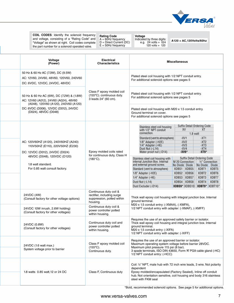
Voltage (Power)
Electrical Characteristics Miscellaneous
50 Hz & 60 Hz AC (7.3W), DC (9.5W)
AC: 12V60, 24V60, 48V60, 120V60, 240V60
DC: 6VDC, 12VDC, 24VDC, 48VDC
Class F epoxy molded coil (155ºC). continuous duty. 3 leads 24” (60 cm).
Plated steel coil housing with 1/2 NPT conduit entry.For additional solenoid options see pages 5
50 Hz & 60 Hz AC (6W), DC (7.2W) & (1.8W)
AC: 12V60 (A012), 24V60 (A024), 48V60 (A048), 120V60 (A120), 240V60 (A120)
DC: 6VDC (D006), 12VDC (D012), 24VDC (D024), 48VDC (D048)
Plated steel coil housing with 1/2 NPT conduit entry.For additional solenoid options see pages 5
Plated steel coil housing with M20 x 1.5 conduit entry. Ground terminal on cover.For additional solenoid options see pages 5
AC: 120V60HZ (A120), 240V60HZ (A240) 110V50HZ (E110), 220V50HZ (E230)
DC: 12VDC (D012), 24VDC (D024) 48VDC (D048), 120VDC (D120)
1.8 watt standard. For 0.85 watt consult factory.
Epoxy molded coils rated for continuous duty, Class H (180°C).
24VDC (4W) (Consult factory for other voltage options)
Continuous duty coil & rectifier, including surge suppression, potted within housing.
Thick wall epoxy coil housing with integral junction box. Internal ground terminal. M20 x 1.5 conduit entry: (-XMAA), (-XMFA), 1/2 NPT conduit entry with adapter: (-XMAF), (-XMFF)24VDC 10W inrush, 2.6W holding)
(Consult factory for other voltages)
Continuous duty coil & power controller potted within housing.
24VDC (0.8W) (Consult factory for other voltages)
Continuous duty coil and power controller potted within housing.
Requires the use of an approved safety barrier or isolator. Thick wall epoxy coil housing and integral junction box. Internal ground terminal. M20 x 1.5 conduit entry: (-XIFA) 1/2 NPT conduit entry with adapter: (-XIFF)
24VDC (1.6 watt max.) System voltage prior to barrier
Class F epoxy molded coil (155ºC). Continuous duty.
Requires the use of an approved barrier or isolator. Maximum operating system voltage before barrier 28VDC. Maximum pilot pressure 115 psi (8 bar). 3 spade terminals, ISO DIN 43650, Form “A” PG9 cable gland (-HC)1/2 NPT conduit entry: (-HCC)
1.8 watts 0.85 watt,12 or 24 DC Class F, Continuous duty
Coil: ½” NPT, male hub with 72 inch wire leads, 3 wire. Not polarity dependentEpoxy molded/encapsulated (Factory Sealed), Inline off conduit hub. Not orientation sensitive, coil housing and body 316 stainless steel with FKM seal
Stainless steel coil housing with internal Junction Box. Internal and external ground screw.
Suffix Detail Ordering CodeM 20 Connection ½” ConnectionNo Diode Diode No Diode Diode
Standard (vent to atmosphere) XDBS1 XDBS5 XDBT1 XDBT51/8” Adapter (-H2E) XDBS2 XDBS6 XDBT2 XDBT61/4” Adapter (-HE) XDBS3 XDBS7 XDBT3 XDBT7Dust Nut (-L14) XDBS4 XDBS8 XDBT4 XDBT8Dust Excluder (-D14) XDBS9* XDBS10 XDBT9* XDBT10*
Stainless steel coil housing with 1/2” NPT conduit connection.
Suffix Detail Ordering CodeXV XT
1.8 wattStandard (vent to atmosphere) -XV1 -XT11/8” Adapter (-H2E) -XV2 -XT21/4” Adapter (-HE) -XV3 -XT3Dust Nut (-L14) -XV4 -XT4Water proof nut (-D14) -XV9* -XT9*
7www.versa-valves.com
Rating Code A = 60Hz frequency D = Direct Current (DC) E = 50Hz frequency
VoltageIndicated by three digits: e.g. 24 volts = 024 120 volts = 120
A120 = AC,120Volts/60hz
COIL CODES: Identify the solenoid frequency and voltage, consisting of a “Rating Code” and “Voltage” as shown at right. Coil codes complete the part number for a solenoid operated valve.
*Bold, recommended solenoid options. See page 5 for additional options.

Function 2-Way NC, 2-Way NO, 3-Way NC, 3-Way NO, Directional & Multi-Purpose
Pressure: Vacuum - 500
Media Air, Oil, Water
Flow: 0.022 to 0.26 Cv
Temperature: 0°F (-18°C) to 180°F (82°C)
Ports, Inlet & Outlet: ⅛” NPT
Exhaust/vent: Vent to atmosphere, #10-32 thread(NPT port or dust protectors available)
Voltages: AC or DC (see page 4)
Coil rating: Class F, continuous duty
Power: 8.5 - 10 .5 Watts
Connections: DIN standard (-HC), Flying Leads (-243)or 1/2” NPT conduit Hub (-228L) optional
Ingress protection: IP65 (-HC), NEMA 1 - 3 (-243), NEMA 4 (-228L)
Materials of construction:
Body: Aluminum
Seals: FKM (fluorocarbon) Coil: Epoxy molded, Class F, continuous duty Manifold: Aluminum
Mounting: (2) threaded holes
Orifice/CvCode Orifice Cv
23468
1/32” 3/64” 1/16” 3/32”1/8"
0.022 0.06 0.11 0.210.26
Mounting holes 8-32 (2)
DIN with PG-9 Cord Grip
Threaded Vent Port
1/8” NPTPorts (2)
OUTIN
2.51 2.51
24” lead length
24” lead length
1/2” NPT Conduit Hub Flying Leads
8 www.versa-valves.com
SERIES EZ
(STANDARD DIN STYLE COIL & CONNECTOR)
Side Ported Types
Shown with-243
Shown with-HC, -H2
Series EZ valves are direct solenoid actuated valves and, physically, are the smallest of the Series E type valves. Ports are 1/8” NPT in the valve body and are individually mounted. See below for technical data.
Series EZ Bantam Multiple Manifold valves are direct solenoid actuated and have 2 to 10 valve cavities within a single body. Each valve within the manifold must be the same and perform the same function. See page 12 for part number example.
Functional Types Available Ports Provided2-way, NC or NO.........................Common inlet, individual outlets3-way, NC................................... Common inlet, individual outlets, exhaust to atmosphere. Common exhaust is available.3-way, NO................................... Common inlet & exhaust, individual outletsMultipurpose..................................Individual “NC,” “COM,” & “NO” ports

SIDE PORTED VALVES
TypeMaximum Operating Pressure Differential
psi (bar)†
Product Numberwith Micromini DIN Style Connector (8 mm gap).
For other housing options see page 4.
Minimum Orifice between Ports Piping Arrangement and Flow Pattern
“NC”- “COM” “COM” - “NO”
TWO-WAY 2/2 NORMALLY CLOSED Air. Oil or Water
500 (34) 400 (27) 200 (14)
150-100 (10-6.8) 65-45 (4.4-3.1)
EZ-2120-0-HC-(*) EZ-2130-0-HC-(*) EZ-2140-0-HC-(*) EZ-2160-0-HC-(*) EZ-2180-0-HC-(*)
1/32” (0.8 mm) 3/64” (1.2 mm) 1/16” (1.6 mm) 3/32” (2.4 mm) 1/8” (3.2 mm)
TWO-WAY 2/2 NORMALLY OPEN Air, Oil or Water
400 (27) 200 (14) 125 (8.6) 40 (2.7)
EZ-2202-H2-HC-(*) EZ-2203-H2-HC-(*) EZ-2204-H2-HC-(*) EZ-2206-H2-HC-(*)
1/32” (0.8 mm) 3/64” (1.2 mm) 1/16” (1.6 mm) 3/32” (2.4 mm)
THREE-WAY 3/2 NORMALLY CLOSED (EXHAUST TO ATMOSPHERE) Air Only
200 (14) 150 (10) 100 (6.9) 50 (3.4) 30 (2.1)
EZ-3122-1-HC-(*) EZ-3133-1-HC-(*) EZ-3144-1-HC-(*) EZ-3166-1-HC-(*) EZ-3186-1-HC-(*)
1/32” (0.8 mm) 3/64” (1.2 mm) 1/16” (1.6 mm) 3/32” (2.4 mm) 1/8” (3.2 mm)
1/32” (0.8 mm) 3/64” (1.2 mm) 1/16” (1.6 mm) 3/32” (2.4 mm) 3/32” (2.4 mm)
THREE-WAY 3/2 NORMALLY CLOSED (PIPED EXHAUST) Air, Oil or Water
200 (14) 150 (10) 100 (6.9) 50 (3.4) 30 (2.1)
EZ-3122-H2-HC-(*) EZ-3133-H2-HC-(*) EZ-3144-H2-HC-(*) EZ-3166-H2-HC-(*) EZ-3186-H2-HC-(*)
1/32” (0.8 mm) 3/64” (1.2 mm) 1/16” (1.6 mm) 3/32” (2.4 mm) 1/8” (3.2 mm)
1/32” (0.8 mm) 3/64” (1.2 mm) 1/16” (1.6 mm) 3/32” (2.4 mm) 3/32” (2.4 mm)
THREE-WAY 3/2 NORMALLY OPEN Air, Oil or Water
150 (10) 125 (8.6) 100 (6.9) 50 (3.4)
EZ-3222-H2-(*) EZ-3233-H2-(*) EZ-3244-H2-(*) EZ-3266-H2-(*)
1/32” (0.8 mm) 3/64” (1.2 mm) 1/16” (1.6 mm) 3/32” (2.4 mm)
1/32” (0.8 mm) 3/64” (1.2 mm) 1/16” (1.6 mm) 3/32” (2.4 mm)
DIRECTIONAL CONTROL 3/2 Air, Oil or Water
300-200 (20-14) 200-150 (14-10) 100-75 (6.9-5.2) 75-40 (5.2-2.7)
EZ-7222-H2-HC-(*) EZ-7233-H2-HC-(*) EZ-7244-H2-HC-(*) EZ-7266-H2-HC-(*)
1/32” (0.8 mm) 3/64” (1.2 mm) 1/16” (1.6 mm) 3/32” (2.4 mm)
1/32” (0.8 mm) 3/64” (1.2 mm) 1/16” (1.6 mm) 3/32” (2.4 mm)
MULTI-PURPOSE 3/2 Air, Oil or Water
125 (8.6) 100 (6.9)
65-50 (4.4-3.4) 25 (1.7)
EZ-8222-H2-HC-(*) EZ-8233-H2-HC-(*) EZ-8244-H2-HC-(*) EZ-8266-H2-HC-(*)
1/32” (0.8 mm) 3/64” (1.2 mm) 1/16” (1.6 mm) 3/32” (2.4 mm)
1/32” (0.8 mm) 3/64” (1.2 mm) 1/16” (1.6 mm) 3/32” (2.4 mm)
Port COM connected to Port NO
DE-ENERGIZED ENERGIZED
NO
COM
NO
Port COM Blocked to Port NO
Port COM = InletPort NO = Outlet
COM
NO
COM
Port COM connected to Port NC
DE-ENERGIZED ENERGIZED
NC
COM
COMPort COM Blocked to Port NC
Port COM = InletPort NC = Outlet
NC NCCOM
NC
NO
COM
Port NC = InletPort Com = Cyl PortPort NO = Exhaust
Port NC connected to Port COM;Port NO blocked
Port NC blocked to Port COM;Port COM connected to Port NO
DE-ENERGIZED ENERGIZED
NC
NO
COM
NC NO
COM
NC
NO
COM
Port COM = Inlet
Port NC = Outlet IIPort NC = Outlet I
Port COM connected to Port NO;Port NC blocked
DE-ENERGIZED ENERGIZED
NC
NO
COM
NC NO
COM
Port COM connected to Port NC;Port NC blocked
NC
DE-ENERGIZED ENERGIZED
NC
NC NO
COMMulti-prupose valves may be used asThree-Way,NC or Three-Way, NO orDirectional Control Valves. Two-Way,NC or Two-Way, NO can be accomplished by plugging the appropriate port.
NC
NO
COMPort NO connected to Port COM;
Port NC blocked
DE-ENERGIZED ENERGIZED
NC
NO
COM
NC NO
COM
Port NO blocked;Port COM connected to Port NC
Port NO = InletPort COM = Cyl PortPort NC = Exhaust
9www.versa-valves.com
NOTES: *Specify Voltage: See "Coil Code" definition page 7. For coil voltages see page 4. †Pressures are for both AC or DC coil unless two pressures are shown. In that case, the pressure in color is for DC. Vacuum is AC only.
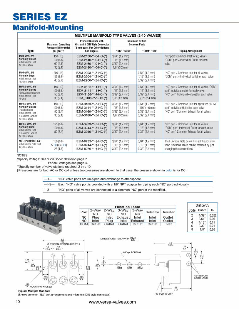
MULTIPLE MANIFOLD TYPE VALVES (2-10 VALVES)
Type
Maximum OperatingPressure Differential
psi (bar)†
Product Number with Micromini DIN Style Connector(8 mm gap). For Other Options
See Page 4.
Minimum OrificeBetween Ports
Piping Arrangement“NC”-”COM” “COM”-”NO”
TWO-WAY, 2/2Normally Closedwith Common InletAir, Oil or Water
150 (10)100 (6.8) 60 (4.1) 30 (2.1)
EZM-2130-**-0-HC-(*)EZM-2140-**-0-HC-(*)EZM-2160-**-0-HC-(*)EZM-2180-**-0-HC-(*)
3/64” (1.2 mm)1/16” (1.6 mm)3/32” (2.4 mm) 1/8” (3.2 mm)
“NC’ port” Common Inlet for a)) valves “COM” port = Individual Outlet for each valve
TWO-WAY. 2/2Normally Openwith Common InletAir, Oil or Water
200 (14)125 (8.6) 40 (2.7)
EZM-2203-**-Z-HC-(*)EZM-2204-**-Z-HC-(*)EZM-2206-**-Z-HC-(*)
3/64” (1.2 mm)1/16” (1.6 mm)3/32” (2.4 mm)
“NO” port = Common Inlet for all valves “COM” port = Individual outlet for each valve
THREE-WAY. 3/2Normally Closed(Exhaust to atmosphere)with Common Inlet Air Only
150 (10)100 (6.8) 50 (3.4) 30 (2.1)
EZM-3133-**-1-HC-(*)EZM-3144-**-1-HC-(*)EZM-3166-**-1-HC-(*)EZM_3186-**-1-HC.(*)
3/64” (1.2 mm)1/16” (1.6 mm)3/32” (2.4 mm)1/8” (3.2 mm)
3/64” (1.2 mm)1/16” (1.6 mm)3/32” (2.4 mm) 3/32” (2.4 mm)
“NC” port = Common Inlet for all valves “COM” port” Individual outlet for each valve“NO” port” Individual exhaust for each valve
THREE-WAY, 3/2Normally Closed (Piped exhaust) with Common Inlet & Common Exhaust Air, Oil or Water
150 (10)100 (6.8) 50 (3.4) 30 (2.1)
EZM-3133-**-Z-HC-(*)EZM-3144-**-Z-HC-(*)EZM-3166-**-Z-HC-(*)EZM-3186-**-Z-HC-(*)
3/64” (1.2 mm)1/16” (1.6 mm)3/32” (2.4 mm) 1/8” (3.2 mm)
3/64” (1.2 mm)1116” (1.6 mm)3/32” (2.4 mm)3/32” (2.4 mm)
“NC” port = Common Inlet for a)) valves “COM” port” Individual Outlet for each valve“NO” port “Common Exhaust for all valves
THREE-WAY, 3/2Normally Open with Common Inlet & Common Exhaust Air, Oil or Water
125 (8.6)100 (6.8) 50 (3.4)
EZM-3233-**-Z-HC-(*)EZM-3244-**-Z-HC-(*)EZM-3266-**-Z-HC-(*)
3/64” (1.2 mm)1/16” (1.6 mm)3/32” (2.4 mm)
3/64” (1.2 mm)1/16” (1.6 mm)3/32” (2.4 mm)
“NO” port = Common Inlet for all valves "COM” port” Individual Outlet for each valve“NO” port” Common Exhaust for all valves
MULTIPURPOSE. 3/2with Common “NC” Port Air, Oil or Water
100 (6.8)65-50 (4.4-3.4)
25 (1.7)
EZM-8233-**-†-HC-(*)EZM-8244-**-†-HC-(*)EZM-8266-**-†-HC-(*)
3/64” (1.2 mm)1/16” (1.6 mm)3/32” (2.4 mm)
3/64” (1.2 mm)1/16” (1.6 mm)3/32” (2.4 mm)
The Function Table below lists all the possible valve functions which can be obtained by just changing the connections
Function Table
Port 2-WayNO
2-WayNC
3-WayNO
3-WayNC Selector Diverter
NC Plug Inlet Exhaust Inlet Inlet OutletNO Inlet Plug Inlet Exhaust Inlet Outlet
COM Outlet Outlet Outlet Outlet Outlet Inlet
Orifice/CvCode Orifice Cv
23468
1/32” 3/64” 1/16” 3/32”1/8"
0.022 0.06 0.11 0.210.26
4.0102
1.025.4
1.025.4
1.025.4
1.025.4
1.7544.5
.256.4
.3759.5
.3759.5
.3759.5
3.0677.8
3.690.5
.512.7
.256.4
1.1429
.1965
COM COM COM
2871.4
PG-9 CORD GRIP
1/8” npt PORT(BOTH ENDS)
MOUNTING HOLE (2)
1/8” npt PORTING
(3 STATION OVERALL LENGTH)
10 www.versa-valves.com
NOTES: *Specify Voltage: See "Coil Code" definition page 7. For coil voltages see page 4.**Specify number of valve stations required, 2 thru 10.†Pressures are for both AC or DC coil unless two pressures are shown. In that case, the pressure shown in color is for DC.
—1— “NO” valve ports are un-piped and exchange to atmosphere.
—H2— Each “NO” valve port is provided with a 1/8” NPT adapter for piping each “NO” port individually.
—Z— “NO” ports of all valves are connected to a common “NO” port in the manifold.
DIMENSIONS: (SHOWN IN ) INCHMM
Typical Multiple Manifold(Shows common “NO” port arrangement and micromini DIN style connector)
SERIES EZManifold-Mounting

Function: 2-Way NC, 2-Way NO, 3-Way NC, 3-Way NO, Directional & Multi-Purpose
Pressure: to 500 psi (see table page 13 - 14)
Media: Air, Oil, Water
Flow: 0.022 to 0.26 Cv
Temperature: 0°F to 180°F (-18°C to 82°C)
Ports, Inlet & Outlet: ⅛” or ¼” NPT
Exhaust/vent: Vent to atmosphere, #10-32 thread(NPT port or dust protectors available)
Voltages: AC or DC (General Purpose see page 4) (Hazardous Location see page 7)
Coil rating: Class F, continuous duty (Class H optional)
Power: 8.5 - 10.5 watt
Connections: ½” NPT
Ingress protection: NEMA 1, 2,3 & 4/4X,
General Purpose NEMA 1, 2,3 & 4/4X,
Hazardous Location NEMA 7, 9, 4/4X, FM & ATEX
Materials of construction:
Body: 430 Stainless (316 Stainless Steel optional)
Seals NBR (Nitrile)
Coil: Epoxy molded
Mounting: (2) threaded holes (optional bracket -WMA)
A B C D E FIN mm IN mm IN mm IN mm IN mm IN mm
1/8” Ports
-HC 3 76.2 1 25.4 1.6 40.6 2.9 73.7 0.67 17 0.3 7.6-243 3 76.2 1 25.4 — — 0.52 13.2 0.69 17.5 0.3 7.6STD 3 76.2 1 25.4 1.26 32 0.52 13.2 1.34 34 0.3 7.6
-XX -XN 3.28 83 1 25.4 1.35 34.3 0.72 18.2 1.5 38.5 0.3 7.6
1/4” Ports
-HC 3.07 78 1.34 .34 1.4 35.6 .75 19 0.67 17 0.34 8.6-243 3.2 81.2 1.34 .34 — — 0.52 13.2 0.69 17.5 0.34 8.6STD 3.2 81.2 1.34 .34 1.09 27.7 0.52 13.2 1.34 34.1 0.34 8.6
XX -XN 3.3 83 1.34 .34 1.48 37.6 0.72 18.3 1.5 38.5 0.34 8.6
B
A
C
E
F
D
B
A
E
F
D
B
A
E
F
D
B
A
E
F
D
C
.4411.1
.4411.1
.4411.1
.4411.1
.307.5
.307.5
.205.2
.205.2
Mounting Hole Dimension1/8” Body 1/4” Body
11www.versa-valves.com
Series E5 compact valves are direct acting solenoid actuated Valves. They are physically smaller than the Series E full-size valves described on pages 18 through 21, but offer most of the same orifice sizes and operating pressure ranges as the larger valves. Ports are 1/8 NPT in the valve body and the valves are individually mounted.
GENERAL PURPOSE COILS(NEMA 1, 2, 3)
HAZARDOUS LOCATION COILS (NEMA 7 & 9)
SERIES E5Side Ported Types
1/8” NPT Ports 1/4” NPT Ports
1/4” NPT Ports
1/8” NPT Ports

Type
Maximum Operating Pressure
Differential psi (bar)
General Purpose (For Coil Voltages See Page 4)
Min. Orifice between Ports
Product Number
AC DC1/8”
BODY PORTS1/4”
BODY PORTS “A”-“B” “B”-“C”
Piping Arrangement and Flow Pattern
TWO-WAY 2/2 NORMALLY CLOSED Air. Oil or Water
500 (34) 400 (27) 200 (14) 100 (6.9) 75 (5.2)
250 (17) 150 (10) 100 (6.9) 45 (3.1) 25 (1.7)
E5SM-2201-20-(*) E5SM-2201-30-(*) E5SM-2201-40-(*) E5SM-2201-60-(*) E5SM-2201-80-(*)
E5SM-2301-20-(*) E5SM-2301-30-(*) E5SM-2301-40-(*) E5SM-2301-60-(*) E5SM-2301-80-(*)
1/32” (0.8 mm) 3/64” (1.2 mm) 1/16” (1.6 mm) 3/32” (2.4 mm) 1/8” (3.2 mm)
TWO-WAY 2/2 NORMALLY OPEN Air, Oil or Water
400 (27) 200 (14) 125 (8.6)
200 (14) 100 (6.9) 60 (4.1)
E5SM-2202-03-H2.(*) E5SM-2202-04-H2-(*) E5SM-2202-06-H2-(*)
E5SM-2302-03-H2.(*) E5SM-2302-04-H2-(*) E5SM-2302-06-H2-(*)
3/64” (1.2 mm) 1/16” (1.6 mm) 3/32” (0.8 mm))
THREE-WAY 3/2 NORMALLY CLOSED (EXHAUST TO ATMOSPHERE) Air Only
200 (14) 150 (10) 150 (10) 100 (6.9) 60 (4.1) 30 (2.1)
200 (14) 150 (10) 150 (10) 100 (6.9) 60 (4.1) 30 (2.1)
E5SM-3201-22-(*) E5SM-3201-33-(*) E5SM-3201-34-(*) E5SM-3201-44-(*) E5SM-3201-64-(*) E5SM-3201-84-(*)
E5SM-3301-22-(*) E5SM-3301-33-(*) E5SM-3301-34-(*) E5SM-3301-44-(*) E5SM-3301-64-(*) E5SM-3301-84-(*)
1/32” (0.8 mm) 3/64” (1.2 mm) 3/64” (1.2 mm) 1/16” (1.6 mm) 3/32” (2.4 mm) 1/8” (3.2 mm)
1/32” (0.8 mm) 3/64” (1.2 mm) 1/16” (1.6 mm) 1/16” (1.6 mm) 1/16” (1.6 mm) 1/16” (1.6 mm)
THREE-WAY 3/2 NORMALLY CLOSED (PIPED EX-HAUST) Air, Oil or Water
200 (14) 150 (10) 150 (10) 100 (6.9) 60 (4.1) 30 (2.1)
200 (14) 150 (10) 150 (10) 100 (6.9) 60 (4.1) 30 (2.1)
E5SM-3201-22-H2-(*) E5SM-3201-33-H2-(*) E5SM-3201-34-H2-(*) E5SM-3201-44-H2-(*) E5SM-3201-64-H2-(*) E5SM-3201-84-H2-(*)
E5SM-3301-22-H2-(*) E5SM-3301-33-H2-(*) E5SM-3301-34-H2-(*) E5SM-3301-44-H2-(*) E5SM-3301-64-H2-(*) E5SM-3301-84-H2-(*)
1/32” (0.8 mm) 3/64” (1.2 mm) 3/64” (1.2 mm) 1/16” (1.6 mm) 3/32” (2.4 mm) 1/8” (3.2 mm)
1/32” (0.8 mm) 3/64” (1.2 mm) 1/16” (1.6 mm) 1/16” (1.6 mm) 1/16” (1.6 mm) 1/16” (1.6 mm)
THREE-WAY 3/2 NORMALLY OPEN Air, Oil or Water
150 (10) 125 (8.6) 100 (6.9) 75 (5.2)
150 (10) 125 (8.6) 75(5.2) 45 (3.1)
E5SM-3202-22-H2-(*) E5SM-3202-33-H2-(*) E5SM-3202-44-H2-(*) E5SM-3202-64-H2-(*)
E5SM-3302-22-H2-(*) E5SM-3302-33-H2-(*) E5SM-3302-44-H2-(*) E5SM-3302-64-H2-(*)
1/32” (0.8 mm) 3/64” (1.2 mm) 1/16” (1.6 mm) 3/32” (2.4 mm)
1/32” (0.8 mm) 3/64” (1.2 mm) 1/16” (1.6 mm) 1/16” (1.6 mm)
THREE-WAY 3/2 DIRECTIONAL CONTROL Air, Oil or Water
300 (21) 200 (14) 100 (6.9) 75 (5.2)
200 (14) 100 (6.9) 50 (3.4) 25 (1.7)
E5SM-7202-22-H2-(*) E5SM-7202-33-H2-(*) E5SM-7202-44-H2-(*) E5SM-7202-64-H2-(*)
E5SM-7302-22-H2-(*) E5SM-7302-33-H2-(*) E5SM-7302-44-H2-(*) E5SM-7302-64-H2-(*)
1/32” (0.8 mm) 3/64” (1.2 mm) 1/16” (1.6 mm) 3/32” (2.4 mm)
1/32” (0.8 mm) 3/64” (1.2 mm) 1/16” (1.6 mm) 1/16” (1.6 mm)
THREE-WAY 3/2 MULTI- PURPOSE Air, Oil or Water
125 (8.6) 100 (6.9) 65 (4.5)
125 (8.6) 100 (6.9) 50 (3.4)
E5SM-8202-22-H2-(*) E5SM-8202-33-H2-(*) E5SM-8202-44-H2-(*)
E5SM-8302-22-H2-(*) E5SM-8302-33-H2-(*) E5SM-8302-44-H2-(*)
1/32” (0.8 mm) 3/64” (1.2 mm) 1/16” (1.6 mm)
1/32” (0.8 mm) 3/64” (1.2 mm) 1/16” (1.6 mm)
Port B connected to Port A
DE-ENERGIZED ENERGIZED
A
B
Port B Blocked to Port A
Port B = InletPort A = Outlet
AB AB
C
BPort B connected to Port C
DE-ENERGIZED ENERGIZED
C
B
C
B
Port B Blocked to Port C
Port B = InletPort C = Outlet
A
C
B
Port A = InletPort B = Cyl PortPort C = Exhaust
Port A connected to Port B;Port C blocked
Port A blocked to Port B;Port B connected to Port C
DE-ENERGIZED ENERGIZED
A
C
B
A C
B
A
C
BPort C connected to Port B;
Port A blocked
DE-ENERGIZED ENERGIZED
A
C
B
A C
B
Port C blocked;Port B connected to Port A
Port C = InletPort B = Cyl PortPort A = Exhaust
A
C
B
Port B = Inlet
Port A = Outlet IIPort C = Outlet I
Port B connected to Port C;Port A blocked
DE-ENERGIZED ENERGIZED
A
C
B
A C
B
Port B connected to Port A;Port C blocked
C
DE-ENERGIZED ENERGIZED
C
A C
BMulti-prupose valves may be used asThree-Way,NC or Three-Way, NO orDirectional Control Valves. Two-Way,NC or Two-Way, NO can be accomplished by plugging the appropriate port.
12 www.versa-valves.com
SERIES E5Side Ported Types
NOTES: *Specify Voltage: See "Coil Code" definition page 7. For General Purpose coil voltages see page 4. For Hazardous Location coil voltages see page 7.

Type
Maximum Operating Pressure
Differential psi (bar)
General Purpose (For Coil Voltages See Page 4)
Min. Orifice between Ports
Product Number
AC DC1/8”
BODY PORTS1/4”
BODY PORTS “A”-“B” “B”-“C”
Piping Arrangement and Flow Pattern
TWO-WAY 2/2 NORMALLY CLOSED Air. Oil or Water
500 (34) 400 (27) 200 (14) 100 (6.9) 75 (5.2)
250 (17) 150 (10) 100 (6.9) 45 (3.1) 25 (1.7)
E5SM-2201-20-(*) E5SM-2201-30-(*) E5SM-2201-40-(*) E5SM-2201-60-(*) E5SM-2201-80-(*)
E5SM-2301-20-(*) E5SM-2301-30-(*) E5SM-2301-40-(*) E5SM-2301-60-(*) E5SM-2301-80-(*)
1/32” (0.8 mm) 3/64” (1.2 mm) 1/16” (1.6 mm) 3/32” (2.4 mm) 1/8” (3.2 mm)
TWO-WAY 2/2 NORMALLY OPEN Air, Oil or Water
400 (27) 200 (14) 125 (8.6)
200 (14) 100 (6.9) 60 (4.1)
E5SM-2202-03-H2.(*) E5SM-2202-04-H2-(*) E5SM-2202-06-H2-(*)
E5SM-2302-03-H2.(*) E5SM-2302-04-H2-(*) E5SM-2302-06-H2-(*)
3/64” (1.2 mm) 1/16” (1.6 mm) 3/32” (0.8 mm))
THREE-WAY 3/2 NORMALLY CLOSED (EXHAUST TO ATMOSPHERE) Air Only
200 (14) 150 (10) 150 (10) 100 (6.9) 60 (4.1) 30 (2.1)
200 (14) 150 (10) 150 (10) 100 (6.9) 60 (4.1) 30 (2.1)
E5SM-3201-22-(*) E5SM-3201-33-(*) E5SM-3201-34-(*) E5SM-3201-44-(*) E5SM-3201-64-(*) E5SM-3201-84-(*)
E5SM-3301-22-(*) E5SM-3301-33-(*) E5SM-3301-34-(*) E5SM-3301-44-(*) E5SM-3301-64-(*) E5SM-3301-84-(*)
1/32” (0.8 mm) 3/64” (1.2 mm) 3/64” (1.2 mm) 1/16” (1.6 mm) 3/32” (2.4 mm) 1/8” (3.2 mm)
1/32” (0.8 mm) 3/64” (1.2 mm) 1/16” (1.6 mm) 1/16” (1.6 mm) 1/16” (1.6 mm) 1/16” (1.6 mm)
THREE-WAY 3/2 NORMALLY CLOSED (PIPED EX-HAUST) Air, Oil or Water
200 (14) 150 (10) 150 (10) 100 (6.9) 60 (4.1) 30 (2.1)
200 (14) 150 (10) 150 (10) 100 (6.9) 60 (4.1) 30 (2.1)
E5SM-3201-22-H2-(*) E5SM-3201-33-H2-(*) E5SM-3201-34-H2-(*) E5SM-3201-44-H2-(*) E5SM-3201-64-H2-(*) E5SM-3201-84-H2-(*)
E5SM-3301-22-H2-(*) E5SM-3301-33-H2-(*) E5SM-3301-34-H2-(*) E5SM-3301-44-H2-(*) E5SM-3301-64-H2-(*) E5SM-3301-84-H2-(*)
1/32” (0.8 mm) 3/64” (1.2 mm) 3/64” (1.2 mm) 1/16” (1.6 mm) 3/32” (2.4 mm) 1/8” (3.2 mm)
1/32” (0.8 mm) 3/64” (1.2 mm) 1/16” (1.6 mm) 1/16” (1.6 mm) 1/16” (1.6 mm) 1/16” (1.6 mm)
THREE-WAY 3/2 NORMALLY OPEN Air, Oil or Water
150 (10) 125 (8.6) 100 (6.9) 75 (5.2)
150 (10) 125 (8.6) 75(5.2) 45 (3.1)
E5SM-3202-22-H2-(*) E5SM-3202-33-H2-(*) E5SM-3202-44-H2-(*) E5SM-3202-64-H2-(*)
E5SM-3302-22-H2-(*) E5SM-3302-33-H2-(*) E5SM-3302-44-H2-(*) E5SM-3302-64-H2-(*)
1/32” (0.8 mm) 3/64” (1.2 mm) 1/16” (1.6 mm) 3/32” (2.4 mm)
1/32” (0.8 mm) 3/64” (1.2 mm) 1/16” (1.6 mm) 1/16” (1.6 mm)
THREE-WAY 3/2 DIRECTIONAL CONTROL Air, Oil or Water
300 (21) 200 (14) 100 (6.9) 75 (5.2)
200 (14) 100 (6.9) 50 (3.4) 25 (1.7)
E5SM-7202-22-H2-(*) E5SM-7202-33-H2-(*) E5SM-7202-44-H2-(*) E5SM-7202-64-H2-(*)
E5SM-7302-22-H2-(*) E5SM-7302-33-H2-(*) E5SM-7302-44-H2-(*) E5SM-7302-64-H2-(*)
1/32” (0.8 mm) 3/64” (1.2 mm) 1/16” (1.6 mm) 3/32” (2.4 mm)
1/32” (0.8 mm) 3/64” (1.2 mm) 1/16” (1.6 mm) 1/16” (1.6 mm)
THREE-WAY 3/2 MULTI- PURPOSE Air, Oil or Water
125 (8.6) 100 (6.9) 65 (4.5)
125 (8.6) 100 (6.9) 50 (3.4)
E5SM-8202-22-H2-(*) E5SM-8202-33-H2-(*) E5SM-8202-44-H2-(*)
E5SM-8302-22-H2-(*) E5SM-8302-33-H2-(*) E5SM-8302-44-H2-(*)
1/32” (0.8 mm) 3/64” (1.2 mm) 1/16” (1.6 mm)
1/32” (0.8 mm) 3/64” (1.2 mm) 1/16” (1.6 mm)
Standard Wattage
Maximum Operating Pressure
Differential psi (bar)†
HAZARDOUS LOCATION VALVES(For Coil Voltages See Page 7)
Product Number (For Coil Voltages
See Page 7)
Recommended Product Numbers
1/8” BODY PORTS 1/4” BODY PORTS
AC or DC 1.8 Watt 0.85 Watt 1.8 Watt 0.85 Watt
E5SM-2201-20-XX-(*) E5SM-2201-30-XX-(*) E5SM-2201-40-XX-(*) E5SM-2201-60-XX-(*) E5SM-2201-80-XX-(*)
120 (8.3) 80 (5.5) 50 (3.4)
E5SM-2201-20-LB-XX-(*) E5SM-2201-30-LB-XX-(*) E5SM-2201-40-LB-XX-(*)
E5SM-2201-20-LA-XX-(*)(DC Voltage Only)
E5SM-2301-20-LB-XX-(*) E5SM-2301-30-LB-XX-(*) E5SM-2301-40-LB-XX-(*)
E5SM-2301-20-LA-XX-(*)(DC Voltage Only)
E5SM-2202-02-H2-XX-(*) E5SM-2202-03-H2-XX-(*) E5SM-2202-04-H2-XX-(*)
200 (13.8)120 (8.3) 50 (3.4)
E5SM-2202-02-H2-LB-XX-(*)E5SM-2202-03-H2-LB-XX-(*) E5SM-2202-04-H2-LB-XX-(*)
—E5SM-2302-02-H2-LB-XX-(*)E5SM-2302-03-H2-LB-XX-(*) E5SM-2302-04-H2-LB-XX-(*)
—
E5SM-3201-22-XX-(*) E5SM-3201-33-XX-(*) E5SM-3201-34-XX-(*) E5SM-3201-44-XX-(*) E5SM-3201-64-XX-(*) E5SM-3201-84-XX-(*)
120 (8.3) 60 (4.1) 30 (2.1)
E5SM-3201-23-LB-XX-(*) E5SM-3201-33-LB-XX-(*) E5SM-3201-44-LB-XX-(*)
E5SM-3201-22-LA-XX-(*)(DC Voltage Only)
E5SM-3301-23-LB-XX-(*) E5SM-3301-33-LB-XX-(*) E5SM-3301-44-LB-XX-(*)
E5SM-3301-22-LA-XX-(*)(DC Voltage Only)
E5SM-3201-22-H2-XX-(*) E5SM-3201-33-H2-XX-(*) E5SM-3201-34-H2-XX-(*) E5SM-3201-44-H2-XX-(*) E5SM-3201-64-H2-XX-(*) E5SM-3201-84-H2-XX-(*)
120 (8.3) 60 (4.1) 30 (2.1)
E5SM-3201-23-H2-LB-XX-(*) E5SM-3201-33-H2-LB-XX-(*) E5SM-3201-44-H2-LB-XX-(*)
E5SM-3201-22-H2-LB-XX-(*)(DC Voltage Only)
E5SM-3301-23-H2-LB-XX-(*) E5SM-3301-33-H2-LB-XX-(*) E5SM-3301-44-H2-LB-XX-(*)
E5SM-3301-22-H2-LB-XX-(*)(DC Voltage Only)
E5SM-3202-22-H2-XX-(*) E5SM-3202-33-H2-XX-(*) E5SM-3202-44-H2-XX-(*) E5SM-3202-64-H2-XX-(*)
E5SM-7202-22-H2-XX-(*) E5SM-7202-33-H2-XX-(*) E5SM-7202-44-H2-XX-(*) E5SM-7202-64-H2-XX-(*)
E5SM-8202-22-H2-XX-(*) E5SM-8202-33-H2-XX-(*) E5SM-8202-44-H2-XX-(*) Orifice/Cv
Code Orifice Cv
23468
1/32” 3/64” 1/16” 3/32”1/8”
0.022 0.06 0.11 0.21 0.26
13www.versa-valves.com
1/8” Body 1/2” NPT Conduit
Connector(-XX Type)
1/4” Body M20” Conduit
Connector(-XN Type)
For higher pressures and temperature see E4 on page 14
†60 psi maximum pressure for 1.8 Watt in hydraulic applications. 0.85 Watt pneumatic only.

S e g u r a n c a
EI xS e g u r a n c a
EI xXV -XT
CSANorth American
Cl I, DIV I Grp B, C, DCl II, DIV I, Grp E, F, GCl I, DIV II, Grp A, B, C, DCl II, DIV I, Grp E, F, GCl III
CL, I, Zn 1 A/Ex de IIC TCL, II Zn, 21 AEx tD A21,DIP A21
ATEX
—
II 2 GDEx d e IIC T4 GbEx tb IIIC IP66 T4C Db
IECExEx d e IIC T4 GbEx tb IIIC IP66 T4C Db
INMETROEx d e IIC T4 GbEx tb IIIC IP66 T4C Db
Russia,Kazakhstan and Belarus
Ex d e IIC T4 GbEx tb IIIC IP66 T4 Db
Stainless steel coil housing
Popular Options Packages
Solenoid Ordering Code 1.8 Watt
Solenoid Ordering Code 0.85 Watt
North American World North
American World
Standard (vent to atmosphere) -XV1 -XT1 -XV1C -XT1C
1/8” Adapter (-H2E) -XV2 -XT2 -XV2C -XT2C
1/4” Adapter (-HE) -XV3 -XT3 -XV3C -XT3C
Dust Nut (-L14) -XV4 -XT4 -XV4C -XT4C
Dust Nut (-D14) -XV9 -XT9 -XV9C -XT9C
Function: 2-Way NC, 2-Way NO, 3-Way NC, 3-Way NO, Directional & Multi-Purpose
Pressure: to 400 psi (see selector table)
Media Air, Oil, Water
Flow: 0.022 to 0.26 Cv (see selector table)
Temperature: +5°F to 194°F (-15°C to 90°C) -40°F to 194°F (-40°C to 90°C)(low temp option -44)
Ports, Inlet & Outlet: ⅛” or ¼” NPT
Exhaust/vent: Vent to atmosphere, #10-32 thread(NPT port or dust protectors available)
Voltages: AC or DC (see page 7)
Coil rating: Class H, continuous duty
Power: 1.8 or 0.85 watt
Connections: ½” NPT
Ingress protection: IP 66/67/68 NEMA 4X, 6P
Materials of construction:
Body: 430 Stainless (316 Stainless Steel optional)
Seals FKM-fluorocarbon (Low Temp Nitrile optional)
Coil: Epoxy molded
Mounting: (2) threaded holes (optional bracket -WMA)
Orifice/CvCode Orifice Cv
23468
1/32” 3/64” 1/16” 3/32”1/8"
0.022 0.06 0.11 0.210.26
Excluders Hydraulic Adapter-L14
Dust Proof-D14
Water TightH2EHE
1/8"1/4"
14 www.versa-valves.com
XV & XT World Solenoid ValvesA compact, heavy duty solenoid valve for hazardous location service. Valve and solenoid housing are stainless steel for superior corrosion resistance. Worldwide certifications available. Valves available in 2-Way, 3-Way, selector or diverter functions. All products are rated for air, gas, oil or water. Porting available in 1/8” or 1/4” NPT for tubing convenience.
SERIES E4
XT solenoid shown with:-H2E Hyd Adapter And -G5R Override
XV solenoid shown with: -D14 Dust Excluder And -G Override
Options - Suffix Details
*Bold, recommended solenoid options. See page 5 for additional options.
-G
-M
-M5R
-G5R
Overrides

1.8 WattProduct Selector
Maximum Differential/Operating Pressurepsi (bar)
Orifice/Flow Product NumberFor Pneumatic and Hydraulic Service
“A” to “B” “B” to “C” 1/8” NPT 1/4” NPT
TYPE Media In (mm) Cv In (mm) Cv
TWO-WAY 2/2NORMALLY
CLOSED
400 (27.6)300 (20.7)200 (13.8)100 (6.9)50 (3.4)
1/32” (0.8 mm)3/64” (1.2 mm)1/16” (1.6 mm)3/32” (2.4 mm)1/8” (3.2 mm)
0.0220.060.110.210.26
E4SM-2201-20-X**-(*)E4SM-2201-30-X**-(*)E4SM-2201-40-X**-(*)E4SM-2201-60-X**-(*)E4SM-2201-80-X**-(*)
E4SM-2301-20-X**-(*)E4SM-2301-30-X**-(*)E4SM-2301-40-X**-(*)E4SM-2301-60-X**-(*)E4SM-2301-80-X**-(*)
TWO-WAY 2/2NORMALLY
OPEN
300 (20.7)150 (10.3)100 (6.9)50 (3.4)
1/32” (0.8 mm)3/64” (1.2 mm)1/16” (1.6 mm)3/32” (2.4 mm)
0.0220.060.110.21
E4SM-2202-02-X**-(*)E4SM-2202-03-X**-(*)E4SM-2202-04-X**-(*)E4SM-2202-06-X**-(*)
E4SM-2302-02-X**-(*)E4SM-2302-03-X**-(*)E4SM-2302-04-X**-(*)E4SM-2302-06-X**-(*)
THREE-WAY 3/2NORMALLY
CLOSED(Exhaust to atm)
200 (13.8)175 (12.1)125 (8.6)75 (5.2)
1/32” (0.8 mm)3/64” (1.2 mm)1/16” (1.6 mm)3/32” (2.4 mm)
0.0220.060.110.21
3/64” (1.2 mm)1/16” (1.6 mm)1/16” (1.6 mm)1/16” (1.6 mm)
0.060.110.110.11
E4SM-3201-23-X**-(*)E4SM-3201-34-X**-(*)E4SM-3201-44-X**-(*)E4SM-3201-64-X**-(*)
E4SM-3301-23-X**-(*)E4SM-3301-34-X**-(*)E4SM-3301-44-X**-(*)E4SM-3301-64-X**-(*)
THREE-WAY 3/2NORMALLY
CLOSED(Piped exhaust)
200 (13.8)175 (12.1)125 (8.6)75 (5.2)
1/32” (0.8 mm)3/64” (1.2 mm)1/16” (1.6 mm)3/32” (2.4 mm)
0.0220.060.110.21
3/64” (1.2 mm)1/16” (1.6 mm)1/16” (1.6 mm)1/16” (1.6 mm)
0.060.110.110.11
E4SM-3201-23-X**-(*)E4SM-3201-34-X**-(*)E4SM-3201-44-X**-(*)E4SM-3201-64-X**-(*)
E4SM-3301-23-X**-(*)E4SM-3301-34-X**-(*)E4SM-3301-44-X**-(*)E4SM-3301-64-X**-(*)
THREE-WAY 3/2NORMALLY
OPEN
150 (10.3)100 (6.9)75 (5.2)50 (3.4)
1/32” (0.8 mm)3/64” (1.2 mm)1/16” (1.6 mm)3/32” (2.4 mm)
.0220.060.110.21
1/32” (0.8 mm)3/64” (1.2 mm)1/16” (1.6 mm)1/16” (1.6 mm)
.0220.060.110.11
E4SM-3202-22-X**-(*)E4SM-3202-33-X**-(*)E4SM-3202-44-X**-(*)E4SM-3202-64-X**-(*)
E4SM-3302-22-X**-(*)E4SM-3302-33-X**-(*)E4SM-3302-44-X**-(*)E4SM-3302-64-X**-(*)
THREE-WAY 3/2DIRECTIONAL
CONTROL
250 (17.2)200 (13.8)150 (10.3)120 (8.3)
1/32” (0.8 mm)3/64” (1.2 mm)1/16” (1.6 mm)3/32” (2.4 mm)
.0220.060.110.21
1/32” (0.8 mm)3/64” (1.2 mm)1/16” (1.6 mm)1/16” (1.6 mm)
0.0220.060.110.11
E4SM-7202-22-X**-(*)E4SM-7202-33-X**-(*)E4SM-7202-44-X**-(*)E4SM-7202-64-X**-(*)
E4SM-7302-22-X**-(*)E4SM-7302-33-X**-(*)E4SM-7302-44-X**-(*)E4SM-7302-64-X**-(*)
THREE-WAY 3/2MULTI-PURPOSE
150 (10.3)75 (5.2)60 (4.1)30 (2.1)
1/32” (0.8 mm)3/64” (1.2 mm)1/16” (1.6 mm)3/32” (2.4 mm)
.0220.060.110.21
1/32” (0.8 mm)3/64” (1.2 mm)1/16” (1.6 mm)1/16” (1.6 mm)
0.0220.060.110.11
E4SM-8202-22-X**-(*)E4SM-8202-33-X**-(*)E4SM-8202-44-X**-(*)E4SM-8202-64-X**-(*)
E4SM-8302-22-X**-(*)E4SM-8302-33-X**-(*)E4SM-8302-44-X**-(*)E4SM-8302-64-X**-(*)
0.85 Watt Product Selector
Maximum Differential/Operating Pressurepsi (bar)
Orifice/Flow Product NumberFor Pneumatic and Hydraulic Service
“A” to “B” “B” to “C”1/8” NPT 1/4” NPT
TYPE Media In (mm) Cv In (mm) CvTWO-WAY 2/2NORMALLY
CLOSED
250 (17.2)150 (10.3)80 (5.5
1/32” (0.8 mm)3/64” (1.2 mm)1/16” (1.6 mm)
0.0220.060.11
E4SM-2201-20-X***-(*)E4SM-2201-30-X***-(*)E4SM-2201-40-X***-(*)
E4SM-2301-20-X***-(*)E4SM-2301-30-X***-(*)E4SM-2301-40-X***-(*)
TWO-WAY 2/2NORMALLY OPEN
175 (12.1)100 (6.9)
1/32” (0.8 mm)3/64” (1.2 mm)
0.0220.06
E4SM-2202-02-X***-(*)E4SM-2202-03-X***-(*)
E4SM-2302-02-X***-(*)E4SM-2302-03-X***-(*)
THREE-WAY 3/2NORMALLY
CLOSED(Exhaust to atm)
150 (10.3)125 (8.6)100 (6.9)75 (5.2)50 (3.4)25 (1.7)
1/32” (0.8 mm)3/64” (1.2 mm)3/64” (1.2 mm)1/16” (1.6 mm)3/32” (2.4 mm)3/32” (2.4 mm)
0.0220.060.060.110.210.21
3/64” (1.2 mm)3/64” (1.2 mm)1/16” (1.6 mm)1/16” (1.6 mm)1/16” (1.6 mm)3/32” (2.4 mm)
0.060.060.110.110.110.21
E4SM-3201-23-X***-(*)E4SM-3201-33-X***-(*)E4SM-3201-34-X***-(*)E4SM-3201-44-X***-(*)E4SM-3201-64-X***-(*)E4SM-3201-66-X***-(*)
E4SM-3301-23-X***-(*)E4SM-3301-33-X***-(*)E4SM-3301-34-X***-(*)E4SM-3301-44-X***-(*)E4SM-3301-64-X***-(*)E4SM-3301-66-X***-(*)
THREE-WAY 3/2NORMALLY
CLOSED(Piped exhaust)
150 (10.3)125 (8.6)100 (6.9)75 (5.2)50 (3.4)25 (1.7)
1/32” (0.8 mm)3/64” (1.2 mm)3/64” (1.2 mm)1/16” (1.6 mm)3/32” (2.4 mm)3/32” (2.4 mm)
0.0220.060.060.110.210.21
3/64” (1.2 mm)3/64” (1.2 mm)1/16” (1.6 mm)1/16” (1.6 mm)1/16” (1.6 mm)3/32” (2.4 mm)
0.060.060.110.110.110.21
E4SM-3201-23-X***-(*)E4SM-3201-33-X***-(*)E4SM-3201-34-X***-(*) E4SM-3201-44-X***-(*)E4SM-3201-64-X***-(*) E4SM-3201-66-X***-(*)
E4SM-3301-23-X***-(*)E4SM-3301-33-X***-(*)E4SM-3301-34-X***-(*) E4SM-3301-44-X***-(*)E4SM-3301-64-X***-(*) E4SM-3301-66-X***-(*)
THREE-WAY 3/2NORMALLY
OPEN
125 (8.6)100 (6.9)60 (4.1)
1/32” (0.8 mm)3/64” (1.2 mm)1/16” (1.6 mm)
0.0220.060.11
1/32” (0.8 mm)3/64” (1.2 mm)1/16” (1.6 mm)
0.0220.060.11
E4SM-3202-22-X***-(*)E4SM-3202-33-X***-(*)E4SM-3202-44-X***-(*)
E4SM-3302-22-X***-(*)E4SM-3302-33-X***-(*)E4SM-3302-44-X***-(*)
THREE-WAY 3/2DIRECTIONAL
CONTROL
110 (7.6)100 (6.9)80 (5.5
1/32” (0.8 mm)3/64” (1.2 mm)1/16” (1.6 mm)
0.0220.060.11
1/32” (0.8 mm)3/64” (1.2 mm)1/16” (1.6 mm)
0.220.060.11
E4SM-7202-22-X***-(*)E4SM-7202-33-X***-(*)E4SM-7202-44-X***-(*)
E4SM-7302-22-X***-(*)E4SM-7302-33-X***-(*)E4SM-7302-44-X***-(*)
THREE-WAY 3/2MULTI-PURPOSE
125 (8.6)100 (6.9)40 (2.8)
1/32” (0.8 mm)3/64” (1.2 mm)1/16” (1.6 mm)
0.0220.060.11
1/32” (0.8 mm)3/64” (1.2 mm)1/16” (1.6 mm)
0.0220.060.11
E4SM-8202-22-X***-(*)E4SM-8202-33-X***-(*)E4SM-8202-44-X***-(*)
E4SM-8302-22-X***-(*)E4SM-8302-33-X***-(*)E4SM-8302-44-X***-(*)
15www.versa-valves.com
*Voltages 0.85 Watt: 12 vdc (-D012), 24 vdc (-D024), 48 vdc (-D048) ***Solenoid Options: Select options from “Solenoid Ordering Code 0.85 Watt” page 14. e.g.: E4SM-3201-23-XT2C-Voltage
*Voltages 1.8 watt: AC 120/60 (-A120), 110/50 (-E110), 240/60 (-A240), 220/50 (-E220); 12 vdc (-D012), DC 24 vdc (-D024), 48 vdc (-D048), 110 vdc (-D110), 220 vdc (D220)**Solenoid Options: Select options from “Solenoid Ordering Code 1.8 Watt” page 14. e.g.: E4SM-3201-23-XV2-Voltage

S e g u r a n c a
EI x
-XDBS M20 x 1,5 XDBT ½” NPT
CSANorth American
NA
Cl I, DIV I Grp B, C, DCl II, DIV I, Grp E, F, GCl I, DIV II, Grp A, B, C, DCl II, DIV I, Grp E, F, GCl III
ATEXII 2 GDEx d e IIC T4 GbEx tb IIIC IP66 T4C Db
II 2 GDEx d e IIC T4 GbEx tb IIIC IP66 T4C Db
IECExEx d e IIC T4 GbEx tb IIIC IP66 T4C Db
Ex d e IIC T4 GbEx tb IIIC IP66 T4C Db
INMETROEx d e IIC T4 GbEx tb IIIC IP66 T4C Db
Ex d e IIC T4 GbEx tb IIIC IP66 T4C Db
Russia,Kazakhstan and Belarus
Ex d e IIC T4 GbEx tb IIIC IP66 T4 Db
Ex d e IIC T4 GbEx tb IIIC IP66 T4 Db
Popular Options Packages
Stainless steel coil housing with internal Junction Box.
Internal and external ground screw.
Suffix Detail Ordering Code*
M 20 Connection ½” Connection
No Diode Diode No Diode Diode
Standard (vent to atmosphere) -XDBS1 -XDBS5 -XDBT1 -XDBT5
1/8” Adapter (-H2E) -XDBS2 -XDBS6 -XDBT2 -XDBT6
1/4” Adapter (-HE) -XDBS3 -XDBS7 -XDBT3 -XDBT7
Dust Nut (-L14) -XDBS4 -XDBS8 -XDBT4 -XDBT8
Dust Nut (-D14) -XDBS9 -XDBS10 -XDBT9 -XDBT10
Function: 2-Way NC, 2-Way NO, 3-Way NC, 3-Way NO, Directional & Multi-Purpose
Pressure: to 400 psi (see selector table)
Media Air, Oil, Water
Flow: 0.022 to 0.26 Cv (see selector table)
Temperature: +5°F to 194°F (-15°C to 90°C) -40°F to 194°F (-40°C to 90°C)(low temp option -44)
Ports, Inlet & Outlet: ⅛” or ¼” NPT
Exhaust/vent: Vent to atmosphere, #10-32 thread(NPT port or dust protectors available)
Voltages: AC or DC (see page 7)
Coil rating: Class H, continuous duty
Power: 1.8 or 0.85 watt
Connections: ½” NPT or M20 conduit hub
Ingress protection: IP 66/67/68 NEMA 4X, 6P
Materials of construction:
Body: 430 Stainless (316 Stainless Steel optional)
Seals FKM-fluorocarbon (Low Temp Nitrile optional)
Coil: Epoxy molded
Mounting: (2) threaded holes (optional bracket -WMA)
Excluders Hydraulic Adapter-L14
Dust Proof-D14
Water TightH2EHE
1/8"1/4"
Orifice/CvCode Orifice Cv
23468
1/32” 3/64” 1/16” 3/32”1/8"
0.022 0.06 0.11 0.210.26
16 www.versa-valves.com
XDB World Solenoid ValveA compact, heavy duty solenoid valve with integral junction box for hazardous location service. Valve and junction box are stainless steel for superior corrosion resistance. Worldwide certifications available. Valves available in 2-Way, 3-Way, selectors or diverters functions. All products are rated for air, gas, oil or water. Porting available in 1/8” or 1/4” NPT for tubing convenience.
SERIES E4
*Suffix Details above are for 1.8 watt coils. For 0.85 watt coils add a “C” as last character to above. Example: XDBS1C. Also see "Product Number" tables opposite page for valve part number.*Bold, recommended solenoid options. See page 5 for additional options.
Shown: Dust Nut (-D14), Mounting Bracket (-WMA) and Manual Override (-M)
Options - Suffix Details
-G
-M
-M5R
-G5R
Overrides

1.8 WattProduct Selector
Maximum Differential/Operating Pressurepsi (bar)
Orifice/Flow Product NumberFor Pneumatic and Hydraulic Service
“A” to “B” “B” to “C”1/8” NPT 1/4” NPT
TYPE Media In (mm) Cv In (mm) Cv
TWO-WAY 2/2NORMALLY
CLOSED
400 (27.6)300 (20.7)200 (13.8)100 (6.9)50 (3.4)
1/32” (0.8 mm)3/64” (1.2 mm)1/16” (1.6 mm)3/32” (2.4 mm)1/8” (3.2 mm)
0.0220.060.110.210.26
E4SM-2201-20-XDB**-(*)E4SM-2201-30-XDB**-(*)E4SM-2201-40-XDB**-(*)E4SM-2201-60-XDB**-(*)E4SM-2201-80-XDB**-(*)
E4SM-2301-20-XDB**-(*)E4SM-2301-30-XDB**-(*)E4SM-2301-40-XDB**-(*)E4SM-2301-60-XDB**-(*)E4SM-2301-80-XDB**-(*)
TWO-WAY 2/2NORMALLY
OPEN
300 (20.7)150 (10.3)100 (6.9)50 (3.4)
1/32” (0.8 mm)3/64” (1.2 mm)1/16” (1.6 mm)3/32” (2.4 mm)
0.0220.060.110.21
E4SM-2202-02-XDB**-(*)E4SM-2202-03-XDB**-(*)E4SM-2202-04-XDB**-(*)E4SM-2202-06-XDB**-(*)
E4SM-2302-02-XDB**-(*)E4SM-2302-03-XDB**-(*)E4SM-2302-04-XDB**-(*)E4SM-2302-06-XDB**-(*)
THREE-WAY 3/2NORMALLY
CLOSED(Exhaust to atm)
200 (13.8)175 (12.1)125 (8.6)75 (5.2)
1/32” (0.8 mm)3/64” (1.2 mm)1/16” (1.6 mm)3/32” (2.4 mm)
0.0220.060.110.21
3/64” (1.2 mm)1/16” (1.6 mm)1/16” (1.6 mm)1/16” (1.6 mm)
0.060.110.110.11
E4SM-3201-23-XDB**-(*)E4SM-3201-34-XDB**-(*)E4SM-3201-44-XDB**-(*)E4SM-3201-64-XDB**-(*)
E4SM-3301-23-XDB**-(*)E4SM-3301-34-XDB**-(*)E4SM-3301-44-XDB**-(*)E4SM-3301-64-XDB**-(*)
THREE-WAY 3/2NORMALLY
CLOSED(Piped exhaust)
200 (13.8)175 (12.1)125 (8.6)75 (5.2)
1/32” (0.8 mm)3/64” (1.2 mm)1/16” (1.6 mm)3/32” (2.4 mm)
0.0220.060.110.21
3/64” (1.2 mm)1/16” (1.6 mm)1/16” (1.6 mm)1/16” (1.6 mm)
0.060.110.110.11
E4SM-3201-23-XDB**-(*)E4SM-3201-34-XDB**-(*)E4SM-3201-44-XDB**-(*) E4SM-3201-64-XDB**-(*)
E4SM-3301-23-XDB**-(*)E4SM-3301-34-XDB**-(*)E4SM-3301-44-XDB**-(*)E4SM-3301-64-XDB**-(*)
THREE-WAY 3/2NORMALLY
OPEN
150 (10.3)100 (6.9)75 (5.2)50 (3.4)
1/32” (0.8 mm)3/64” (1.2 mm)1/16” (1.6 mm)3/32” (2.4 mm)
.0220.060.110.21
1/32” (0.8 mm)3/64” (1.2 mm)1/16” (1.6 mm)1/16” (1.6 mm)
.0220.060.110.11
E4SM-3202-22-XDB**-(*)E4SM-3202-33-XDB**-(*)E4SM-3202-44-XDB**-(*)E4SM-3202-64-XDB**-(*)
E4SM-3302-22-XDB**-(*)E4SM-3302-33-XDB**-(*)E4SM-3302-44-XDB**-(*)E4SM-3302-64-XDB**-(*)
THREE-WAY 3/2DIRECTIONAL
CONTROL
250 (17.2)200 (13.8)150 (10.3)120 (8.3)
1/32” (0.8 mm)3/64” (1.2 mm)1/16” (1.6 mm)3/32” (2.4 mm)
.0220.060.110.21
1/32” (0.8 mm)3/64” (1.2 mm)1/16” (1.6 mm)1/16” (1.6 mm)
0.0220.060.110.11
E4SM-7202-22-XDB**-(*)E4SM-7202-33-XDB**-(*)E4SM-7202-44-XDB**-(*)E4SM-7202-64-XDB**-(*)
E4SM-7302-22-XDB**-(*)E4SM-7302-33-XDB**-(*)E4SM-7302-44-XDB**-(*)E4SM-7302-64-XDB**-(*)
THREE-WAY 3/2MULTI-PURPOSE
150 (10.3)75 (5.2)60 (4.1)30 (2.1)
1/32” (0.8 mm)3/64” (1.2 mm)1/16” (1.6 mm)3/32” (2.4 mm)
.0220.060.110.21
1/32” (0.8 mm)3/64” (1.2 mm)1/16” (1.6 mm)1/16” (1.6 mm)
0.0220.060.110.11
E4SM-8202-22-XDB**-(*)E4SM-8202-33-XDB**-(*)E4SM-8202-44-XDB**-(*)E4SM-8202-64-XDB**-(*)
E4SM-8302-22-XDB**-(*)E4SM-8302-33-XDB**-(*)E4SM-8302-44-XDB**-(*)E4SM-8302-64-XDB**-(*)
0.85 Watt Product Selector
Maximum Differential/Operating Pressurepsi (bar)
Orifice/Flow Product NumberFor Pneumatic and Hydraulic Service
“A” to “B” “B” to “C”1/8” NPT 1/4” NPT
TYPE Media In (mm) Cv In (mm) CvTWO-WAY 2/2NORMALLY
CLOSED
250 (17.2)150 (10.3)80 (5.5
1/32” (0.8 mm)3/64” (1.2 mm)1/16” (1.6 mm)
0.0220.060.11
E4SM-2201-20-XDB***(*)E4SM-2201-30-XDB***(*)E4SM-2201-40-XDB***(*)
E4SM-2301-20-XDB***(*)E4SM-2301-30-XDB***(*)E4SM-2301-40-XDB***(*)
TWO-WAY 2/2NORMALLY OPEN
175 (12.1)100 (6.9)
1/32” (0.8 mm)3/64” (1.2 mm)
0.0220.06
E4SM-2202-02-XDB***(*)E4SM-2202-03-XDB***(*)
E4SM-2302-02-XDB***(*)E4SM-2302-03-XDB***(*)
THREE-WAY 3/2NORMALLY
CLOSED(Exhaust to atm)
150 (10.3)125 (8.6)100 (6.9)75 (5.2)50 (2.8)25 (1.7)
1/32” (0.8 mm)3/64” (1.2 mm)3/64” (1.2 mm)1/16” (1.6 mm)3/32” (2.4 mm)3/32” (2.4 mm)
0.0220.060.060.110.210.21
3/64” (1.2 mm)3/64” (1.2 mm)1/16” (1.6 mm)1/16” (1.6 mm)/1/16” (1.6 mm)3/32” (2.4 mm)
0.060.060.110.110.110.21
E4SM-3201-23-XDB***(*)E4SM-3201-33-XDB***(*)E4SM-3201-34-XDB***(*)E4SM-3201-44-XDB***(*)E4SM-3201-64-XDB***(*)E4SM-3201-66-XDB***(*)
E4SM-3301-23-XDB***(*)E4SM-3301-33-XDB***(*)E4SM-3301-34-XDB***(*)E4SM-3301-44-XDB***(*)E4SM-3301-64-XDB***(*)E4SM-3301-66-XDB***(*)
THREE-WAY 3/2NORMALLY
CLOSED(Piped exhaust)
150 (10.3)125 (8.6)100 (6.9)75 (5.2)50 (2.8)25 (1.7)
1/32” (0.8 mm)3/64” (1.2 mm)3/64” (1.2 mm)1/16” (1.6 mm)3/32” (2.4 mm)3/32” (2.4 mm)
0.0220.060.060.110.210.21
3/64” (1.2 mm)3/64” (1.2 mm)1/16” (1.6 mm)/1/16” (1.6 mm)1/16” (1.6 mm)3/32” (2.4 mm)
0.060.060.110.110.110.21
E4SM-3201-23-XDB***(*)E4SM-3201-33-XDB***(*)E4SM-3201-34-XDB***(*) E4SM-3201-44-XDB***(*)E4SM-3201-64-XDB***(*) E4SM-3201-66-XDB***(*)
E4SM-3301-23-XDB***(*)E4SM-3301-33-XDB***(*)E4SM-3301-34-XDB***(*) E4SM-3301-44-XDB***(*)E4SM-3301-64-XDB***(*) E4SM-3301-66-XDB***(*)
THREE-WAY 3/2NORMALLY
OPEN
125 (8.6)100 (6.9)60 (4.1)
1/32” (0.8 mm)3/64” (1.2 mm)1/16” (1.6 mm)
0.0220.060.11
1/32” (0.8 mm)3/64” (1.2 mm)1/16” (1.6 mm)
0.0220.060.11
E4SM-3202-22-XDB***(*)E4SM-3202-33-XDB***(*)E4SM-3202-44-XDB***(*)
E4SM-3302-22-XDB***(*)E4SM-3302-33-XDB***(*)E4SM-3302-44-XDB***(*)
THREE-WAY 3/2DIRECTIONAL
CONTROL
110 (7.6)100 (6.9)80 (5.5
1/32” (0.8 mm)3/64” (1.2 mm)1/16” (1.6 mm)
0.0220.060.11
1/32” (0.8 mm)3/64” (1.2 mm)1/16” (1.6 mm)
0.220.060.11
E4SM-7202-22-XDB***(*)E4SM-7202-33-XDB***(*)E4SM-7202-44-XDB***(*)
E4SM-7302-22-XDB***(*)E4SM-7302-33-XDB***(*)E4SM-7302-44-XDB***(*)
THREE-WAY 3/2MULTI-PURPOSE
125 (8.6)100 (6.9)40 (2.8)
1/32” (0.8 mm)3/64” (1.2 mm)1/16” (1.6 mm)
0.0220.060.11
1/32” (0.8 mm)3/64” (1.2 mm)1/16” (1.6 mm)
0.0220.060.11
E4SM-8202-22-XDB***(*)E4SM-8202-33-XDB***(*)E4SM-8202-44-XDB***(*)
E4SM-8302-22-XDB***(*)E4SM-8302-33-XDB***(*)E4SM-8302-44-XDB***(*)
17www.versa-valves.com
*Voltages: AC 120/60 (-A120), 110/50 (-E110), 240/60 (-A240), 220/50 (-E220) DC 24 vdc (-D024), 48 vdc (-D048), 12 vdc (-D012), 110 vdc (-D110), 220 vdc (D220)
**Product Number. Complete product number by inserting one of the following in place of the **: S1 = M20 conduit connection, no diode, T1 = ½” npt conduit connection no diode, S5 = M20 conduit connection with diode, T5 = ½” npt conduit connection with diode.
*Voltages: 24 vdc (-D024), 48 vdc (-D048), 12 vdc (-D012)
***Product Number. Complete product number by inserting one of the following in place of the ***: S1C = M20 conduit connection, no diode, T1C = ½” npt conduit connection no diode, S5C = M20 conduit connection with diode, T5C = ½” npt conduit connection with diode.

Function 2-Way NC, 2-Way NO, 3-Way NC, 3-Way NO, Directional & Multi-Purpose.
Pressure: to 250 psi (see table page 19)
Media: Air, Oil, Water
Flow: 0.022 to 0.79 Cv (see table below)
Temperature: 0°F to 180°F (-18°C to 82°C)
Ports, Inlet & Outlet: ⅛” or ¼” NPT
Exhaust/vent: Vent to atmosphere, 5/16-18 thread(NPT port or dust protectors available)
Voltages: AC or DC (General Purpose see page 4) (Hazardous Location see page 7)
Coil rating: Class F, continuous duty (Class H optional)
Power: 7.3 - 12 watt
Connections: ½” NPT
Ingress protection: NEMA 1, 2,3 & 4/4X
General Purpose NEMA 1, 2,3 & 4/4X
Hazardous Location NEMA 7, 9 & 4/4X
Materials of construction:
Body: 430 Stainless (316 Stainless Steel optional)
Seals NBR (Nitrile)
Coil: Epoxy molded
Mounting: (2) threaded holes (optional bracket -WE)
Orifice/CvCode Orifice Cv
23468101216
1/32” 3/64” 1/16” 3/32”1/8”5/32”3/16”1/4”
0.022 0.06 0.11 0.21 0.26 0.45 0.56 0.79
2.8271.6
3.2281.8
2.1654.9
2.3960.7
.88 22.4
.88 22.4
.44 11.2
.44 11.2
.317.9
.317.9
.7519
1.8446.7
.348.6
.62 15.7
1.62 ø41
PORTED ADAPTER-SPECIFY-H FOR 1/4 NPT-H2 FOR 1/8”NPT
24” (61 cm) COIL LEADS#18AWG WIRE
1/2”NPT.CONDUIT CONNECTION
OPTIONALMANUAL OVERRIDE
1/8 OR 1/4” NPT.( 2 PORTS)
#10 - 32 UNF - 2Bx .31 THREAD DEPTH( 2 MOUNTING HOLES )
.7519
1.88ø47.8
.348.6
.62 15.7
1.62 ø41
C
B
C
B
24” (61 cm) GROUND LEAD (GREEN)
2.5965.8
.88 22.4
.88 22.4
.44 11.2
.44 11.2
B
A
PORTED ADAPTER-SPECIFY-H FOR 1/4 NPT-H2 FOR 1/8”NPT
24” (61 cm) COIL LEADS#18AWG WIRE
1/2” NPT.CONDUIT CONNECTION
OPTIONALMANUAL OVERRIDE
1/8 OR 1/4” NPT.( 2 PORTS)
#10 - 32 UNF - 2Bx .31 THREAD DEPTH( 2 MOUNTING HOLES )
B
A
18 www.versa-valves.com
Color shows piped port C or normally open valve; metric dimensions.Coil cover shown is supplied as standard and provides housing with threaded boss for conduit connection. Other housing types are available. See page 4.
SERIES E
Series E Full-Size Side-Ported valves are direct solenoid actuated and are individually mounted. 1/8 NPT or 1/4 NPT ports are provided in the valve body.
DIMENSIONS SHOWN IN INCH MM
Side Ported Types
GENERAL PURPOSE(NEMA 1,2,3)
HAZARDOUS LOCATIONS(NEMA 7&9)
ORDINARY LOCATIONS
HAZARDOUS LOCATIONS
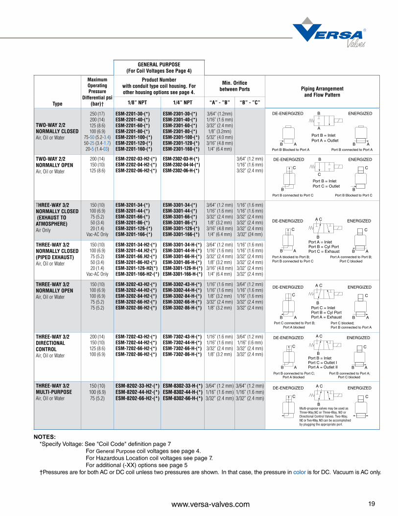
GENERAL PURPOSE (For Coil Voltages See Page 4)
Type
Maximum Operating Pressure
Differential psi (bar)†
Product Numberwith conduit type coil housing. For other housing options see page 4.
Min. Orifice between Ports Piping Arrangement
and Flow Pattern1/8” NPT 1/4” NPT “A” - ”B” “B” - ”C”
TWO-WAY 2/2 NORMALLY CLOSED Air, Oil or Water
250 (17) 200 (14) 125 (8.6) 100 (6.9)
75-50 (5.2-3.4) 50-25 (3.4-1.7) 20-5 (1.4-03)
ESM-2201-30-(*) ESM-2201-40-(*) ESM-2201-60-(*) ESM-2201-80-(*) ESM-2201-100-(*) ESM-2201-120-(*) ESM-2201-160-(*)
ESM-2301-30-(*) ESM-2301-40-(*) ESM-2301-60-(*) ESM-2301-80-(*) ESM-2301-100-(*) ESM-2301-120-(*) ESM-2301-160-(*)
3/64” (1.2mm) 1/16” (1.6 mm) 3/32” (2.4 mm) 1/8” (3.2mm)
5/32” (4.0 mm) 3/16” (4.8 mm) 1/4” (6.4 mm)
TWO-WAY 2/2 NORMALLY OPEN Air, Oil or Water
200 (14) 150 (10) 125 (8.6)
ESM-2202-03-H2-(*) ESM-2202-04-H2-(*) ESM-2202-06-H2-(*)
ESM-2302-03-H-(*) ESM-2302-04-I4-(*) ESM-2302-06-H-(*)
3/64” (1.2 mm) 1/16” (1.6 mm) 3/32” (2.4 mm)
THREE-WAY 3/2 NORMALLY CLOSED (EXHAUST TO ATMOSPHERE) Air Only
150 (10) 100 (6.9) 75 (5.2) 50 (3.4) 20 (1.4)
Vac-AC Only
ESM-3201-34-(*) ESM-3201-44-(*) ESM-3201-66-(*) ESM-3201-86-(*) ESM-3201-126-(*) ESM-3201-166-(*)
ESM-3301-34-(*) ESM-3301-44-(*) ESM-3301-66-(*) ESM-3301-86-(*) ESM-3301-126-(*) ESM-3301-166-(*)
3/64” (1.2 mm) 1/16” (1.6 mm) 3/32” (2.4 mm) 1/8” (3.2 mm)
3/16” (4.8 mm) 1/4” (6.4 mm)
1/16” (1.6 mm) 1/16” (1.6 mm) 3/32” (2.4 mm) 3/32” (2.4 mm) 3/32” (2.4 mm) 3/32” (24 mm)
THREE-WAY 3/2 NORMALLY CLOSED (PIPED EXHAUST) Air, Oil or Water
150 (10) 100 (6.9) 75 (5.2) 50 (3.4) 20 (1.4)
Vac-AC Only
ESM-3201-34-H2-(*) ESM-3201-44.H2-(*) ESM-3201-66.H2-(*) ESM-3201-86-H2-(*) ESM-3201-126-H2(*) ESM-3201-166-H2-(*)
ESM-3301-34-H-(*) ESM-3301-44-H-(*) ESM-3301-66-H-(*) ESM-3301-86-H-(*) ESM-3301-126-H-(*) ESM-3301-166-H-(*)
3/64” (1.2 mm) 1/16” (1.6 mm) 3/32” (2.4 mm) 1/8” (3.2 mm)
3/16” (4.8 mm) 1/4” (6.4 mm)
1/16” (1.6 mm) 1/16” (1.6 mm) 3/32” (2.4 mm) 3/32” (2.4 mm) 3/32” (2.4 mm) 3/32” (2.4 mm)
THREE-WAY 3/2 NORMALLY OPEN Air, Oil or Water
150 (10) 100 (6.9) 100 (6.9) 75 (5.2) 75 (5.2)
ESM-3202-43-H2-(*) ESM-3202-44-H2-(*) ESM-3202-84-H2-(*) ESM-3202-66-H2-(*) ESM-3202-86-H2-(*)
ESM-3302-43-H-(*)ESM-3302-44-H-(*)ESM-3302-84-H-(*)ESM-3302-66-H-(*)ESM-3302-86-H-(*)
1/16” (1.6 mm) 1/16” (1.6 mm) 1/8” (3.2 mm)
3/32” (2.4 mm) 1/8” (3.2 mm)
3/64” (1.2 mm) 1/16” (1.6 mm) 1/16” (1.6 mm) 3/32” (2.4 mm) 3/32” (2.4 mm)
THREE-WAY 3/2 DIRECTIONAL CONTROL Air, Oil or Water
200 (14) 150 (10) 125 (8.6) 100 (6.9)
ESM-7202-43-H2-(*) ESM-7202-44-H2-(*) ESM-7202-66-H2-(*) ESM-7202-86-H2-(*)
ESM-7302-43-H-(*) ESM-7302-44-H-(*) ESM-7302-66-H-(*) ESM-7302-86-H-(*)
1/16” (1.6 mm) 1/16” (1.6 mm) 3/32” (2.4 mm) 1/8” (3.2 mm)
3/64” (1.2 mm) 1/16” (l.6 mm) 3/32” (2.4 mm) 3/32” (2.4 mm)
THREE-WAY 3/2 MULTI-PURPOSE Air, Oil or Water
150 (10) 100 (6.9) 75 (5.2)
ESM-8202-33-H2-(*) ESM-8202-44-H2-(*) ESM-8202-66-H2-(*)
ESM-8302-33-H-(*) ESM-8302-44-H-(*) ESM-8302-66-H-(*)
3/64” (1.2 mm) 1/16” (1.6 mm) 3/32” (2.4 mm)
3/64” (1.2 mm) 1/16” (1.6 mm) 3/32” (2.4 mm)
Port B connected to Port A
DE-ENERGIZED ENERGIZED
A
B
Port B Blocked to Port A
Port B = InletPort A = Outlet
AB AB
C
BPort B connected to Port C
DE-ENERGIZED ENERGIZED
C
B
C
B
Port B Blocked to Port C
Port B = InletPort C = Outlet
A
C
B
Port A = InletPort B = Cyl PortPort C = Exhaust
Port A connected to Port B;Port C blocked
Port A blocked to Port B;Port B connected to Port C
DE-ENERGIZED ENERGIZED
A
C
B
A C
B
A
C
BPort C connected to Port B;
Port A blocked
DE-ENERGIZED ENERGIZED
A
C
B
A C
B
Port C blocked;Port B connected to Port A
Port C = InletPort B = Cyl PortPort A = Exhaust
A
C
B
Port B = Inlet
Port A = Outlet IIPort C = Outlet I
Port B connected to Port C;Port A blocked
DE-ENERGIZED ENERGIZED
A
C
B
A C
B
Port B connected to Port A;Port C blocked
C
DE-ENERGIZED ENERGIZED
C
A C
BMulti-prupose valves may be used asThree-Way,NC or Three-Way, NO orDirectional Control Valves. Two-Way,NC or Two-Way, NO can be accomplished by plugging the appropriate port.
19www.versa-valves.com
NOTES: *Specify Voltage: See "Coil Code" definition page 7 For General Purpose coil voltages see page 4. For Hazardous Location coil voltages see page 7. For additional (-XX) options see page 5 †Pressures are for both AC or DC coil unless two pressures are shown. In that case, the pressure in color is for DC. Vacuum is AC only.

Function 2-Way NC, 2-Way NO, 3-Way NC, 3-Way NO, Directional & Multi-Purpose
Pressure: to 250 psi (see table page 21)
Media: Air, Oil, Water
Flow: 0.022 to 0.79 Cv (see Orifice/Cv table page 21)
Temperature: 0°F to 180°F (-18°C to 82°C)
Ports, Inlet & Outlet: ⅛” or ¼” NPT
Exhaust/vent: Vent to atmosphere, #10-32 thread(NPT port or dust protectors available)
Voltages: AC or DC (General Purpose see page 4) (Hazardous Location see page 7)
Coil rating: Class F, continuous duty (Class H optional)
Power: 7.3 - 12 watt
Connections: ½” NPT
Ingress protection: NEMA 1, 2,3 & 4/4X
General Purpose NEMA 1, 2,3 & 4/4X
Hazardous Location NEMA 7, 9 & 4/4X
Materials of construction:
Body: 430 Stainless (316 Stainless Steel optional)
Seals NBR (Nitrile)
Coil: Epoxy molded
Manifold: Aluminum
Mounting: (2) threaded holes (optional bracket -WE)
1.25(31.6)
8.3(210.8)
1.8(45.2)
1.25(31.6)
2.9(74.3) 4.6
(116.8)4.7
(119.4)
6.6(167.6)
1.8(45.2)
1.25(31.6)
-HCShown: STD -243
BlankingPlate
2.0(50.8)
20 www.versa-valves.com
Each Series E Full-Size Manifold Mounting valve is direct solenoid actuated and is mounted on a manifold which can have 1 to 10 valve stations. The manifolds are provided with the threaded ports for pipe connections, which allows the valves to be easily and swiftly installed or removed without breaking any pipe connections. The manifolds also provide common ports, such as the inlet and exhaust, making only one such connection necessary per manifold. Installation is neater and maintenance easier since valves are grouped in one location. Several different piping arrangements are available to provide flexibility of application.Valves are supplied assembled to manifolds, but must be ordered separately. Station Blanks (E-189) are available for blocking off any unused or “future” valve stations on the manifold. To order complete unit, specify manifold desired and quantity and valve model number required. Valves must all be same model.
Manifold-Mounting Types
MANIFOLD FEATURES: Piped Exhaust; Common inlet for all valves; Individual outlets (cylinder ports) for each valve; Common exhaust port for all valves.
DIMENSIONS SHOWN IN INCH (MM)
WITH ELECTRICALPLUG-IN††
(NEMA 1, 2, 3)
Standard Coils(NEMA 1, 2, 3)
SERIES E
Example of coil types on manifold mounted valves. Also available on side ported

THREE-WAY 3/2NORMALLY CLOSED(EXHAUST TOATMOSPHERE) Air Only
150 (10) 100 (6.9) 75 (5.2) 50 (3.4) 20 (1.4)
Vacuum-AC Only
ESM-3011-34-(*) ESM-3011-44-(*) ESM-3011-66-(*) ESM-3011-86-(*) ESM-3011-126-(*) ESM-3011-166-(*)
“In” “Cyl”
“Cyl” “Exh”
EM-31-120-(††) EM-31-220-(††) EM-31-210-(††)3/64” (1.2 mm) 1/16” (1.6 mm) 3/32” (2.4 mm) 1/8” (3.2 mm) 3/16” (4.8 mm) 1/4” (6.4 mm)
1/16” (1.6 mm) 1/16” (1.6 mm) 3/32” (2.4 mm) 3/32” (2.4 mm) 3/32” (2.4 mm) 3/32” (2.4 mm)
THREE-WAY 3/2NORMALLY CLOSED(COMMON PIPED EXHAUST) Air, Oil or Water
150 (10) 100 (6.9) 75 (5.2) 50 (3.4) 20 (1.4)
Vacuum-AC Only
ESM-3011-34-Z-(*) ESM-3011-44-Z-(*) ESM-3011-66-Z-(*) ESM-3011-86-Z-(*) ESM-3011-126-Z-(*) ESM-3011-166-Z-(*)
3/64” (1.2 mm) 1/16” (1.6 mm) 3/32” (2.4 mm) 1/8” (3.2 mm) 3/16” (4.8 mm) 1/4” (6.4 mm)
1/16” (1.6 mm) 1/16” (1.6 mm) 3/32” (2.4 mm) 3/32” (2.4 mm) 3/32” (2.4 mm) 3/32” (2.4 mm)
EM-31-121-(††) EM-31-221-(††)
THREE-WAY 3/2NORMALLY OPEN (COMMON PIPED EXHAUST) Air, Oil or Water
150 (10) 100 (6.9) 100 (6.9 75 (5.2) 75 (5.2)
ESM-3012-43-Z-(*) ESM-3012-44-Z-(*) ESM-3012-84-Z-(*) ESM-3012-66-Z-(*) ESM-3012-86-Z-(*)
1/16” (1.6 mm) 1/16” (1.6 mm) 1/8” (3.2 mm) 3/32” (2.4 mm) 1/8” (3.2 mm)
3/64” (1.2 mm) 1/16” (1.6 mm) 1/16” (1.6 mm) 3/32” (2.4 mm) 3/32” (2.4 mm)
EM-32-121-(††)
THREE-WAY 3/2DIRECTIONAL CONTROL Air, Oil or Water
200 (14) 150 (10) 125 (8.6) 100 (6.9)
ESM-7012-43-Z-(*) ESM-7012-44-Z-(*) ESM-7012-66-Z-(*) ESM-7012-86-Z-(*)
“In” “Out 1”
“In” “Out 2”
EM-72-212-(††)1/16” (1.6 mm) 1/16” (1.6 mm) 3/32” (2.4 mm) 1/8” (3.2 mm)
3/64” (1.2 mm) 1/16” (1.6 mm) 3/32” (2.4 mm) 3/32” (2.4 mm)
Add Suffix -XXto Valve ProductNumbers Shown Above
HAZARDOUSLOCATIONS
GENERAL PURPOSE (For Coil Voltages See Page 4)
Type
Maximum Operating Pressure
Differentialpsi (bar)†
Product Number
Valve Manifold**
Listed with conduit type coil
housing.
Min. Orifice between Valve Ports
One Inlet (3/8 NPT) Serves All Valves: Individual Outlets
(1/4 NPT)
Individual Inlet(1/4 NPT) and
Outlet (1/4 NPT)for Each Valve
Individual Inlet (1/4 NPT) for Each Valve; One Outlet (3/8 NPT) Serves
All
TWO-WAY 2/2NORMALLY CLOSED Air, Oil or Water
250 (17) 200 (14) 125 (8.6
100 (6.9) 75-50 (5.2-3.4) 50-25 (3.4-1.7) 20-5 (1.4- 0.3)
ESM-2011-30-(*) ESM-2011-40-(*) ESM-2011-60-(*) ESM-2011-80-(*) ESM-2011-100-(*) ESM-2011-120-(*) ESM-2011-160-(*)
3/64” (1.2 mm) 1/16” (1.6 mm) 3/32” (2.4 mm) 1/8” (3.2 mm) 5/32” (4.0mm) 3/16” (4.8 mm) 1/4” (6.4 mm)
EM-21-210-(††) EM-21-220-(††) EM-21-120-(††)
TWO-WAY 2/2NORMALLY OPEN Air, Oil or Water
200 (14) 150 (10) 125 (8.6)
ESM-2012-03-Z-(*) ESM-2012-04-Z-(*) ESM-2012-06-Z-(*)
3/64” (1.2 mm) 1/16” (1.6 mm) 3/32” (2.4 mm)
EM-22-012-(††) EM-22-022-(††) —
Orifice/CvCode Orifice Cv
23468101216
1/32” 3/64” 1/16” 3/32”1/8”5/32”3/16”1/4”
0.022 0.06 0.11 0.21 0.26 0.45 0.56 0.79
21www.versa-valves.com
NOTES:*Specify Voltage: See "Coil Code" definition page 7. For General Purpose coil voltages see page 4. For Hazardous Location coil voltages see page 7. For additional (-XX) options see page 5
** All ports of single station manifolds are 1/4 NPT.†Pressures are for both AC or DC coil unless two pressures are shown. In that case, the pressure in color is for DC. Vacuum is AC only.†† Specify number of valve stations required, 1 thru 10. For Plug-In solenoid add (P) (example: EM-31-120-4P).
}{

CSA ATEXStandard Wattage Super Low Wattage Standard Wattage Super Low Wattage
Part Number E3SM-3301-46-316-XPS-*
E3SM-3301-36-316-LC-XPS-*
E3SM-3301-46-316-XPN-*
E3SM-3301-36-316-LC-XPN-*
Pressure 0-150 psi(0-10.3 bar)
0 – 115 psi(0-7.9 bar)
0-150 psi(0-10.3 bar)
0 – 115 psi (0-7.9 bar)
Media Air, Gas, Hydraulic
Flow-Inlet, Cv/orifice: 0.11 / 0.063”(1.6 mm)
0.06 / 0.047”(1.2 mm)
0.11 / 0.063”(1.6 mm)
0.06 / 0.047”(1.2 mm)
Flow-Exhaust, Cv/orifice: 0.16 / 0.094”(2.4 mm)
0.16 / 0.094”(2.4 mm)
0.16 / 0.094”(2.4 mm)
0.16 / 0.094”(2.4 mm)
Power: 1.86 watts 0.85 watt 1.86 watts 0.85 watt
Voltage: 12 or 24 DC± 15%
24 DC± 15%
12 or 24 DC± 15%
24 DC± 15%
Ingress protection: NEMA 4X and 6P IP 66/67
Coil Rating: Class F, Continuous duty
Electrical Connection: ½” npt, male hub with 72 inch wire leads, 3 wire. Not polarity dependent
Ports: ¼” NPT Inlet, Outlet & Exhaust
Temperature -4 to 122 F (-20 to 49 C)
Materials: Body: 316 Stainless Steel
Seals: FKM-fluorocarbon
Coil Housing: 316 Stainless Steel
Coil: Epoxy molded/encapsulated (Factory Sealed)
Mounting: Inline off conduit hub. Not orientation sensitive
Rating: Class I, Div 1, Group C and DClass II, Div 1, Group E, F and G, T6Class I, Div 2, Group C and DClass II, Div 2, Group E, F and G
II 2 G Ex d IIB T4…T6 Gb
C
P E
FLOW SCHEMATIC
MALE CONDUITCONNECTION
5.53141
1.0326.6
0.8722.1HEX
1.8847.8
Ø
C US®
22 www.versa-valves.com
An inline, compact, heavy duty solenoid valve designed for the most extreme environments. Valve and coil housing are stainless steel for superior corrosion resistance and factory sealed. Rated for hazardous location service. Worldwide certifications available. ¼” NPT 3-Way Valves for air, gas, oil or water. Male inline conduit hub for ease of installation. Super low watt option available for applications where power is a premium.
Dimensions
SERIES E3 Inline Valve
*Specify Voltage: 12VDC (D012) or 24VDC (D024)

SUFFIX CHART Description
(for additional specifications contact factory) Suffix
General Purpose E5QE E4QE EQENEMA 1, 1/2” Conduit, 24” wire leads (standard no suffix required) None
NA NANEMA 4, 4X 1/2” Conduit, 24” wire leads -PC
Hazardous LocationUL/CSA Explosion Proof, 1/2” Conduit, 24” wire leads.For other available options see page 5 -XX -XV
NA
ATEX/IEC Flame Proof (d), M20 Conduit, 24” wire leads (-XN).ATEX/IEC Flame Proof (d), 1/2” Conduit, 24” wire leads (-XT).For other available options see page 5
-XN -XT
FM/CSA Intrinsic Safe, Spade terminals. Other available options: -HC DIN Connector, Pg9 cord grip-HCC DIN Connector, 1/2” conduitNote: Part number changes to E5QE-30202-316 and E5QE-50202-316.Pressure is 5-115 psi (0.3-7.9 bar) and Inlet Flow is 0.02 Cv (.32 Kv)
-XISC (FM/CSA)-XISX6 (ATEX) NA
ATEX/IECEx/CSA Flame Proof (d), Increased Safety(e), Enclosure/Dust (td) Class I, Div I, Grp B,C,D - Class I, Div II, Grp E,F,G- Class I, Div III, integral junction box
NA
-XDBS1 (M20)-XDBT1 (½” npt)
ATEX/IECEx Encapsulated (mb), Increased Safety (e) Enclosure/Dust (td) integral junction box
NA
-XMAA (M20)-XMAF (½”)
Intrinsic Safe (ia), integral junction box -XIFA (M20)-XIFF (½” npt)
Function Size
E5QE E4QE EQE
Pressure
General Purpose, NEMA 1 (none)General Purpose, NEMA 4/4X (-PC)
UL/CSA, flying lead ½” condit hub (-XX)ATEX, flying leads M20 conduit hub (-XN)
FM/CSA, Intrinsic Safe, DIN (-XIS*)
CSA/ATEX, junction box (-XDB*1) ATEX, (m) junction box (-XMA*)ATEX, (i) junction box (-XIF*)
3-Way 3/2
Normally Closed
BasicPorts
Part NumberFlow
Part NumberFlow
Part NumberFlow
Inlet Outlet Exhaust Inlet Exhaust Inlet Exhaust Inlet Exhaust
¼ ¼ ¼5-150 E5QE-30304-316-*-** 0.06 3.3 E4QE-30304-316-*-** 0.06 3.3
5-100 E5QE-30404-316-*-** 0.11 3.3 E4QE-30404-316-*-** (125 psi) 0.11 3.3
½ ¼ ½ ¾5-150 E5QE-50304-316-*-** 0.06 8.8 E4QE-50304-316-*-** 0.06 8.8 EQE-50203-316-*-** 0.022 8.8
5-100 E5QE-50404-316-*-** 0.11 8.8 E4QE-50404-316-*-** (125 psi) 0.11 8.8 EQE-50304-316-*-** 0.06 8.8
23www.versa-valves.com
The Electric Quick Exhaust Valve is a three-way, NC, 3/2 valve with extra large exhaust orifice in order to provide extra fast movement of the cylinder rod, or to exhaust systems rapidly. When the solenoid is energized, the outlet port is connected to the inlet port and the exhaust port is closed. When the sole-noid is de-energized, the inlet port is closed and the outlet port is connected to the exhaust port, providing rapid evacuation of the system.
Body: 316 Stainless Steel (Conforms to NACE standard MR-01-75)
Solenoid Operator: 304, 430F & 302 Stainless Steel (wetted parts)
Seals: FKM (Fluorocarbon) O ring seals; CR (Neoprene) coated nylon flapper. Screws: Stainless Steel
Construction
(For Pneumatic Application Only)
Functional Description
* Specify Suffix Options from chart below. **Specify Voltage.
E5QE ¼”with -XX
E4QE ¼”with -XDB
EQE ½” with -XXMA
SERIES EQE Electric Quick Exhaust Valve
83

®
WARNINGS REGARDING THE DESIGN APPLICATION,INSTALLATION AND SERVICE OF VERSA PRODUCTS
The warnings below must be read and reviewed before designing a system utilizing, installing, servicing, or removing a Versa product. Improper use, installation or servicing of a Versa product could create a hazard to personnel and property.
DESIGN APPLICATION WARNINGSVersa products are intended for use where compressed air or industrial hydraulic fluids are present. For use with media other than specified or for non-industrial applications or other applications not within published specifications, consult Versa.
Versa products are not inherently dangerous. They are only a component of a larger system. The system in which a Versa product is used must include adequate safeguards to prevent injury or damage in the event of system or product failure, whether this failure be of switches, regulators, cylinders, valves or any other system component. System designers must provide adequate warnings for each system in which a Versa product is utilized. These warnings, including those set forth herein, should be provided by the designer to those who will come in contact with the system.
Where questions exist regarding the applicability of a Versa product to a given use, inquiries should be addressed directly to the manufacturer. Confirmation should be obtained directly from the manufacturer regarding any questioned application prior to proceeding.
INSTALLATION, OPERATION AND SERVICE WARNINGSDo not install or service any Versa product on a system or machine without first depressurizing the system and turning off any air, fluid, or electricity to the system or machine. All applicable electrical, mechanical, and safety codes, as well as applicable governmental regulations and laws must be complied with when installing or servicing a Versa product.
Versa products should only be installed or serviced by qualified, knowledgeable personnel who understand how these specific products are to be installed and operated. The individual must be familiar with the particular specifications, including specifications for temperature, pressure, lubrication, environment and filtration for the Versa product which is being installed or serviced. Specifications may be obtained upon request directly from Versa. If damages should occur to a Versa product, do not Operate the system containing the Versa product. Consult Versa for technical information.
LIMITED WARRANTY DISCLAIMERAND LIMITATION OF REMEDIESVersa’s Series products are warranted to be free from defective material and workmanship for a period of ten years from the date of manufacture, provided said products are used in accordance with Versa specifications. Versa’s liability pursuant to that warranty is limited to the replacement of the Versa product proved to be defective provided the allegedly defective product is returned to Versa or its authorized distributor. Versa provides no other warranties, expressed or implied, except as stated above. There are no implied warranties of merchantability or fitness for a particular purpose. Versa’s liability for breach of warranty as herein stated is the only and exclusive remedy and in no event shall Versa be responsible or liable for incidental or consequential damages.
Versa Products Company Inc.22 Spring Valley RoadParamus, New Jersey 07652USA Phone: 201-843-2400Fax: 201-843-2931
Versa BVPrins Willem Alexanderlaan 14297321 GB ApeldoornThe NetherlandsPhone: 01131-55-368-1900Fax: 01131-55-368-1909
www.versa-valves.comemail: [email protected]
Versa has beensupplying thefluid power
industry with pneumatic and
hydrauliccomponentsfor over 50years. We
have built areputation forquality that isunsurpassedin the market
for highperformance
solenoids,pneumatic
relays,resets and
pilot valves.