e,,^ - automation-dfw.com · ordering information cs-utrrtr-em sensor model special option switch...
TRANSCRIPT
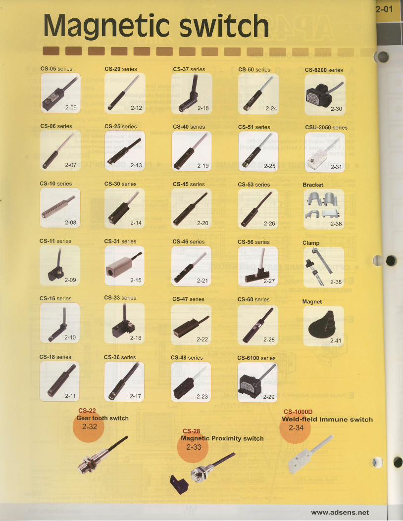
I ICS-05 series
a
.J-taE
v 2-06
CS-06 series
y 2-07
CS-10 series
a
.r7,-
7I
2-08
CS-11 series
e,,^ /^ /,,GS-31 series
l , /J , / / *CS-16 series CS-33 series CS47 series CS-60 series
) l / /
cs-22Gear tooth switch
2,32
F lMagnetic switch I|r I T
CS-20 series
i, 2-12
CS-25 series
ffi *:1ry':
CS-37 series CS-50 series
CS-53 series
(o
CS48 series
cs-28Magnetic Proximity switch
2-33
CS-6200 series
CSU-2050 series
Glamp
\
D9 . I
.a 2_38
Magnet
cs-1000DWeld-field immune switch
2-34
{ , , ^
GS-51 series
/ , , , { , , , 2-31
CS-30 series CS-45 series Bracket
. t ,
2-36
CS-46 series CS-56 series
i o
GS-18 series
, /
fi'I
CS-36 series CS-6100 series
wr'vw.adsens.net

ORDERING INFORMATION
CS-U t rR t r - t rM
sENsoR"L' IH=High Sens i t i v i t y
L=Low Sensitivity
F- P/NC=PNP/N.CL N/NC=NpN/N.C * = Some switch type only available in certain sensor models.
CONNECTION METHOD
2 wire switch connection
General connection
QD=M8 male connector
EQD=M8 male connector
1M=The length o f cab le i s 1 meter
2M=The length of cable is 2 meters
10M=The length o f cab le i s 10 meters
When connecting 2-wire switches in series (AND), don.texceed more than two switches due to the internal voltagedrop (Typical V drop = 2.5-4V per switch). Excessive Voltagedrop will cause non-operation of the load.
1.When connecting non-contact 2-wire switches in parallel(OR), leakage current will increase and cause improper loadoperation.
2.When connecting 2-wire reed switches in parallel (OR),possible concurrent operation will cause dim LEDillumination due to lower current distribution.
3 wire PNP connection
U=3oo
0)
ug!o,9ooo=
L
q)
UL
!
I
U
Parallel Connection (OR)
wire NPN connectaon
General connectionf - - -
Series connection (AND)
Parallel connection (OR)
rs oservs the right to change the specification without prior notice.
I r R=Reed Switch 2 wire type .- X=NO Indjcator
KH=Keeo swttcn J wtre current sourcing
[- RN=Reed Switch 3 wire current sinking-
l- P=Solid state type. Current sourcing(pNp output)
f- N=Solid state type, Current sinking(NpN output)
Brown
2-01www.adsens.net

ORDERING INFORMATION
C S - U t r R t r - E M
SENSOR MODEL SPECIAL OPTION
SWITCH TYPE t-IR=Reed Switch 2 wire type
CABLE LENGTH / QD PINOUT
RP=Reed Switch 3 wire current sourcingRN=Reed Switch 3 wire current sinkingP=Solid state type, Current sourcing(PNP output)N=Solid state type, Current sinking(NPN output)D=Solid state type, 2-Wire
None=Standard Sensitivity
H=High SensitivityL=Low Sensitivity
X=NO Indicator
QD=M8 male connector
EQD=M8 male connector1M=The length of cable is 1 meter2M=The length of cable is 2 meters
1oM=The length of cable is 10 meters
; Series connection (AND)
> Parallel connection (OR)
Special Order is Available
+
When connecting 2-wire switches in series (AND), don'texceed more than two switches due to the internal voltagedrop (Typical V drop = 2,5-4V per switch). Excessive Voltagedrop will cause non-operation of the load.
1.When connectang non-contact 2-wire switches in parallel(OR), leakage current will increase and cause improper loadoperation.
2.When connecting 2-wire reed switches in parallel (OR),possible concurrent operation will cause dim LEDillumination due to lower current distribution.
3 wirg PNP connection
CONNECTION METHOD
2 wire switch connection
) General connection
> Parallel Connection (OR)
3 wire NPN connection
T=TRIAC outout
R/NC=REED/N.C
P/NC=PNP/N.C
N/NC=NPN/N.C * = Some switch type only available in certain sensor models.
l_ _ _:!" j
0c;ooL
ooAJ
o
(J
'os9ooo=
oIUo
o(JL
50:o
> General connection- -arowJ
D
l--- - Bt":
[. U *." O" dght to chang€ tho spoctll€tlon wlthout prlor notlc6.
r2-01 www.adsens.net