dynapak gas sampler probe location and installation 5 5. ... control documentation 29 ... connect...
TRANSCRIPT

DynaPak Gas SamplerS Y S T E M S U P P O R T M A N U A L
DP-2020ARXN


Version 03162005
DynaPak 2020ARXN System Support
Manual

4
1. Introduction 32. System Components 33. Theory of Operation 44. Sample Probe Location and Installation 55. Sampler Installation 66. Sample Vessel Installation 87. Operational Check & Leak Testing 98. Sampler Set-Up: proportional-to-flow sampling 119. Sampler Set-Up: time-based sampling 1510. Sampler Maintenance 1611. Trouble Shooting 1912. Diagrams #1 DP-2000 pump (assembled) 23
#2 DP-2000 pump (exploded) 24#3 YZ filter regulator (assembled) 25#4 YZ filter regulator (exploded) 26#5 Z-200 controller 27#6 LinkPlus 28#7 Z-200 installation notes/wiring
control documentation 29#8 DuraSite portable sample vessel
instructions 3013. Rosemount Differential Pressure Transmitter 31
Table Of Contents

DynaPak 2020ARXN 03162005 ATEX Rev.YZ Systems, Inc. • 3101 Pollok Drive • Conroe, Texas • USA • 77303 • P: 936.788.5593 • F: 936.788.5720
5
1. IntroductionCongratulations on your purchase of the DynaPak 2020Sampler.
Before installation, insure that all of the components arepresent. You may or may not have ordered a samplecylinder with your DynaPak System. Regardless, you willneed a cylinder during installation. If you have any ques-tions about installation/operation, contact your YZ represen-tative or YZ Customer Service at 936.788.5593.
2. System ComponentsThe primary components of the DynaPak 2020 Sampler areillustrated here.
10 1/4"
Relief Valve
Product SupplyLoop
1000500
2000psi
1500PreCharge
300 250275 22580%
175200 150
Y−Z INDUSTRIES, INC.BOX 890 SNYDER, TEXAS 79550
Pressure Switch
2" Pipestand(By Customer)
*Vessel Tray
(By Customer)
ApprovedSystemMutual
Factory
50-75 psiActuation
(Optional)
Product Loop Returnw/Self-Cleaning Screen*Slipstream Adpater
100125 75 2550 0 Product 1000500
2000psi
1500
21 1/8"
Solar Panel Option
psi
ProductSampled
(Optional)
SPO-12
Z-200 Controller

6
DynaPak 2020 Gas Sampler
The DynaPak 2020ARXN Sampler is a remotely mountedmounted sampling system which uses the pneumaticallyoperated, positive displacement DynaPak 2000 pump, theZ-200 timer/controller, a special differential pressuretransmitter, the YZ filter/regulator and a low power solenoidvalve to obtain gas samples. The 2020 has two modes ofoperation:
A. Proportional-to-flow sampling: in this mode of operation, the2020 extracts a gas sample from the pipeline at timeintervals proportional to the pipeline flow rate. The volumeof the sample is set by the operator using the volumeadjustment feature of the DP-2000 pump. The Z-200periodically energizes a low power solenoid valve, whichallows actuation gas to stroke the DP-2000 pump.
The DynaPak 2020 uses a Rosemount differential pressuretransmitter to convert the pressure signal into a 1 - 5 VDCoutput signal. The Z-200 controller uses this 1 - 5 VDCsignal to determine the percentage of flow that is present inthe pipeline.
The Z-200 operates as a recycling timer with exception thatthe off time is adjusted to account for variations in pipelineflow conditions, as indicated by the pressure differentialtransmitter. In the event that flow increases in the pipelinethe time between solenoid actuations will be shortened. Ifthe flow in the pipeline decreases the time betweensolenoid actuations will lengthen. This allowsthe time between solenoid actuations to be directlyproportional-to-flow in the pipeline.
B. Proportional-to-time sampling: in this mode of operation, theZ-200 controller operates as a recycling timer, energizingthe solenoid valve at an interval pre-selected by the operator.As in the other mode of operation, solenoid actuation allowsthe DP-2000 pump to stroke.
In either mode of operation, the number of solenoidactuations is recorded by the onboard LCD indicator. TheZ-200 timer/counter operates using a replaceable internalbattery pack. The battery pack condition is monitored usingtwo indicator LEDs. When the battery pack needs replacement,the red LED will illuminate when the solenoid output isactivated. If the battery pack is good, the green LED willilluminate when the solenoid is activated.
The External Power Option can be used in lieu of theinternal battery pack. The External Power Option (model No.EPO-120) consists of an AC to DC convertor and intrinsicallysafe barrier to convert 120 AC power to 28 VDC to operatethe controller without the use of the internal battery pack.
The Solar Power Option would be used in lieu of theinternal battery pack. The Solar Power Option (model#SPO-12) consists of a 5 watt solar panel with RM-12charger regulator module and internal 12V, 5 Amp hourbattery pack.
3. Theory of Operation

DynaPak 2020ARXN 03162005 ATEX Rev.YZ Systems, Inc. • 3101 Pollok Drive • Conroe, Texas • USA • 77303 • P: 936.788.5593 • F: 936.788.5720
7
4.1 The sample probe should be a minimum of five pipediameters from any device which could cause aerosols orsignificant pressure drops.
4.2 The sample probe should not be located within thedefined meter tube region (AGA 3-1985 ED.).
4.3 The sample probe should be located upstream of thedifferential pressure device.
4.4 The end of the sampler probe should penetrate thecenter 1/3rd of the pipeline.
4.5 The end of the sample probe should be cut parallel tothe pipeline.
A = The number of unobstructed, straight pipe diameters upstream (see AGA - 3 manual).B = The number of unobstructed, straight pipe diameters downstream (see AGA - 3 manual).
4. Sample Probe Location and Installation
Meter Tube
Optimum Sampler Probe Locations
Differential Pressure Device
5 Ø
Flow
A B 5 Ø

8
5. System Installation
FLOW
80%175200 150
Y−Z INDUSTRIES, INC.BOX 890 SNYDER, TEXAS 79550
Element (Optional)
Loop Driverw/Static Mixer(Optional)
(By Customer)
*Vessel Tray
Product Supply
Relief Valve
Static Mixing
Loop
Actuation50-75 psi
(By Customer)2" Pipestand
(Optional)Pressure Switch
SPO-12
*Slipstream Adpaterw/Self-Cleaning Screen
Sample VesselYZ Durasite
Product Loop Return
SampledProduct
Solar Panel Option(Optional)
21 1/8"
10 1/4"
*Denotes Items Included inDP-2020 Slipstream Adapter Kit
FLOW
1000500
2000psi
1500PreCharge
300 250275 225
Z-200 Controller
FactoryMutual
SystemApproved
100125 75 2550 0 Product 1000500
2000psi
1500
psi
CAUTION:Incorrect operation of valves (over tightening)can result in damage to the valve components(isolation valve bonnet assembly) which mightresult in the valve stem being screwed out of theprobe body. This of course results in product atpipeline pressure being vented continuallythrough this port until this section of the pipelineis shut in. Be aware of the following proceduresand information.
· DynaPak valves are of soft seatdesign and should only be closedor opened with fingers. Nowrenches should ever be used.
·If a valve will not seal off withfinger tight operation the valveshould have maintenanceperformed to allow properoperation of the valve.
5.1 DynaPak 2020 With Slipstream Kita. Mount the DP-2020 with slipstream kit on a vertical 2"pole.
b. Connect the slipstream adapter to the pipeline productsupply and product return connections as shown in thediagram.
c. Connect the actuation gas supply (50 - 65psi) to theactuation gas connection located on the left hand side of thesampler.
d. Connect the sample out connection to the sample vessel.
e. Wire the Z-200 to the flow input device (DPT) to be used.Wiring instructions are found in sections 12 and 13.
f. Before applying pipeline pressure to the DP-2020, ensurethat the product supply valve is closed.
g. After pipeline pressure has been applied to the sampler,check the slipstream tubing connections for leaks.
h. Open the product supply valve.
i. Follow the "Operational Check and Leak Testing Proce-dures" detailed in Section 7.

DynaPak 2020ARXN 03162005 ATEX Rev.YZ Systems, Inc. • 3101 Pollok Drive • Conroe, Texas • USA • 77303 • P: 936.788.5593 • F: 936.788.5720
9
5.2 Differential Pressure Transmitter (DPT)
a. With the low pressure supply valve closed and the highpressure supply valve closed, connect the DPT to the orificeconnection tubing.
b. Open the equalization valve.
c. Open the low pressure supply valve or the high pressuresupply valve.
NOTE: Do not open either the low pressure supply valve orthe high pressure supply valve without ensuring that theequalization valve is open.
d. Open the other supply valve.
e. Close the equalization valve.
f. Run the free end of the DPT cable through the cable entryconnector located on the upper left side on the DynaPak2020 enclosure.
g. Connect the DPT cable as shown in the diagram.
h. Tighten the cable entry connector, allowing for enoughcable length to open the enclosure.
High Pressure
EqualizationValve
Isolation Valve
Orifice Connection
FLOW
Isolation ValveLow Pressure
SlimLineManifold
Green
Transmitter
Differential
SHD
White
Red
Black
(DPT)
Pressure
MutualSystemApproved
Factory
Maximum Pressure 2000 PSIA
10
Variable volume/constant pressure cylinder.A free-floating piston cylinder (DuraSite) may be installed ina horizontal position on an optional vessel rack. Free-floating piston cylinders should NOT be installed on theDynaPak BackRack vessel rack.
Install 1/8" tubing from the sample discharge port of themanifold to the product end of the vessel. Avoid traps in thisline.
See diagram #9 for DuraSite portable sample vesselinstructions.
6. Sample Vessel Installation
DynaPak 2020ARXN 03162005 ATEX Rev.YZ Systems, Inc. • 3101 Pollok Drive • Conroe, Texas • USA • 77303 • P: 936.788.5593 • F: 936.788.5720
11
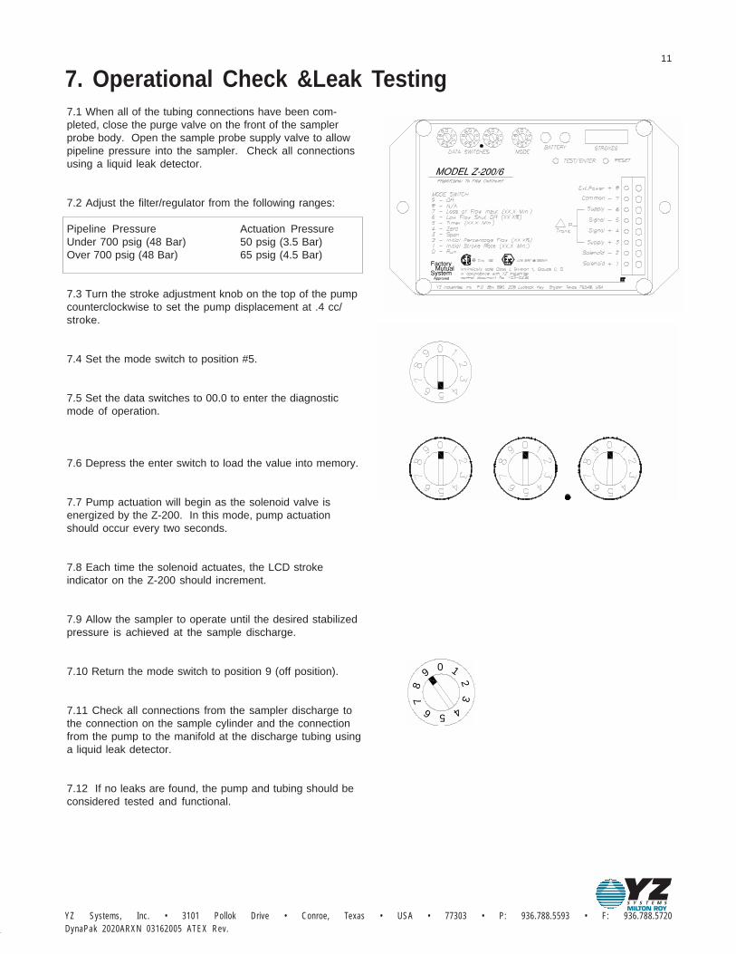
7.1 When all of the tubing connections have been com-pleted, close the purge valve on the front of the samplerprobe body. Open the sample probe supply valve to allowpipeline pressure into the sampler. Check all connectionsusing a liquid leak detector.
7.2 Adjust the filter/regulator from the following ranges:
Pipeline Pressure Actuation PressureUnder 700 psig (48 Bar) 50 psig (3.5 Bar)Over 700 psig (48 Bar) 65 psig (4.5 Bar)
7.3 Turn the stroke adjustment knob on the top of the pumpcounterclockwise to set the pump displacement at .4 cc/stroke.
7.4 Set the mode switch to position #5.
7.5 Set the data switches to 00.0 to enter the diagnosticmode of operation.
7.6 Depress the enter switch to load the value into memory.
7.7 Pump actuation will begin as the solenoid valve isenergized by the Z-200. In this mode, pump actuationshould occur every two seconds.
7.8 Each time the solenoid actuates, the LCD strokeindicator on the Z-200 should increment.
7.9 Allow the sampler to operate until the desired stabilizedpressure is achieved at the sample discharge.
7.10 Return the mode switch to position 9 (off position).
7.11 Check all connections from the sampler discharge tothe connection on the sample cylinder and the connectionfrom the pump to the manifold at the discharge tubing usinga liquid leak detector.
7.12 If no leaks are found, the pump and tubing should beconsidered tested and functional.
7. Operational Check &Leak Testing
MutualSystemApproved
Factory
0
56
9
87 4
1
23

12
Sample pump displacement per stroke Number of turns open on the pump volume knob
.1cc 3
.2cc 6
.4cc 12
In order for the Z-200 controller to operate in the propor-tional-to-flow mode of operation it will be necessary toenter the following parameters:
8.2 Loss of flow input:(XX.X min) Mode #7 Default 20.0 min
The loss of flow input setting is a predetermined amount oftime that the operator would like to see transpire betweenpump strokes in the event that the 1 - 5 VDC flow inputsignal is lost.
To set the loss of flow input:1. Set the mode switch to position #7.2. Set the data switches to the desired timein minutes XX.X minutes.
Ex: 20 minutes = 20.0
3. Depress the enter switch to load thevalue into memory.
NOTE: the green LED will flash if entry is accepted; the redLED will flash if not accepted.
NOTE: Time (20.0 minutes) above corresponds to dial settingshown for the Z-200.1 model. (For the Z-200.10, the time wouldbe 2.00 minutes - the decimal moves one place to the left).
8. Sampler Set-UpProportional-to-flow sampling
In this mode of operation, the Z-200 uses two operatorinputs in conjunction with the 1 - 5 VDC flow input to vary thetime that will transpire between pump strokes.
8.1 Adjust the pump volume adjustment knob to the valueused in the calculation in step 9.1.
MutualSystemApproved
Factory
DynaPak 2020ARXN 03162005 ATEX Rev.YZ Systems, Inc. • 3101 Pollok Drive • Conroe, Texas • USA • 77303 • P: 936.788.5593 • F: 936.788.5720
13
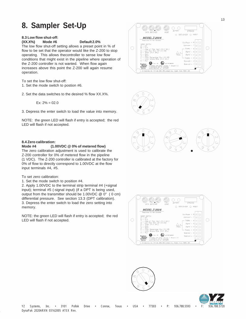
8.3 Low flow shut-off:(XX.X%) Mode #6 Default 2.0%The low flow shut-off setting allows a preset point in % offlow to be set that the operator would like the Z-200 to stopoperating. This allows thecontroller to sense low flowconditions that might exist in the pipeline where operation ofthe Z-200 controller is not wanted. When flow againincreases above this point the Z-200 will again resumeoperation.
To set the low flow shut-off:1. Set the mode switch to postion #6.
2. Set the data switches to the desired % flow XX.X%.
Ex: 2% = 02.0
3. Depress the enter switch to load the value into memory.
NOTE: the green LED will flash if entry is accepted; the redLED will flash if not accepted.
8.4 Zero calibration:Mode #4 (1.00VDC @ 0% of metered flow)The zero calibration adjustment is used to calibrate theZ-200 controller for 0% of metered flow in the pipeline(1 VDC). The Z-200 controller is calibrated at the factory for0% of flow to directly correspond to 1.00VDC at the flowinput terminals #4, #5.
To set zero calibration:1. Set the mode switch to position #4.2. Apply 1.00VDC to the terminal strip terminal #4 (+signalinput); terminal #5 (-signal input) (if a DPT is being used,output from the transmitter should be 1.00VDC @ 0" ( 0 cm)differential pressure. See section 13.3 (DPT calibration).3. Depress the enter switch to load the zero setting intomemory.
NOTE: the green LED will flash if entry is accepted; the redLED will flash if not accepted.
8. Sampler Set-Up
MutualSystemApproved
Factory
MutualSystemApproved
Factory

14
8.5 Span calibration:Mode #3 (5.00VDC @ 100% of metered flow)The span calibration adjustment is used to calibrate theZ-200 controller for 100% of metered flow in the pipeline(5VDC). The Z-200 controller is calibrated at the factory for100% flow to directly correspond to 5.00VDC at the flowinput terminals #4, #5.
To set the span calibration:1. Set the mode switch to postion #3.2. Apply 5.00VDC to the terminal strip terminal #4 (+signalinput); terminal #5 (-signal input)(if a DPT is being used, output from the transmitter shouldbe 5.00VDC @ maximum range of meter. Ex.: 5.00 VDC @100" (254 cm) water differential pressure, See section 13.3DPT calibration).3. Depress the enter switch to load the span setting intomemory.
NOTE: the green LED will flash if entry is accepted; the redLED will flash if not accepted.
NOTE: for maximum accuracy, after setting the span, returnto zero calibration section and repeat both zero and spanprocedures in that order.
8.6 Initial percentage flow:(XX.X%) Mode #2 Default 50.0%The initial percentage flow shoud be set by the operator tothe typical or average % of metered flow that exists in thepipeline. This should be based upon historical flowmeasurement records from the metering device beingused. If the history is not known, use an anticipated value.
To set initial percentage flow:1. Set the mode switch to position #2.2. Set the data switches to the desired % of flow X.XX%.
Ex.: 50% = 50.0
3. Depress the enter switch to load the value into memory.NOTE: the green LED will flash if entry is accepted; the redLED will flash if not accepted.
8. Sampler Set-Up
MutualSystemApproved
Factory
MutualSystemApproved
Factory

DynaPak 2020ARXN 03162005 ATEX Rev.YZ Systems, Inc. • 3101 Pollok Drive • Conroe, Texas • USA • 77303 • P: 936.788.5593 • F: 936.788.5720
15
8.7 Initial stroke rate:(XX.X min) Mode #1 Default 20.0 minThe initial stroke rate is set by the operator to the amount oftime that would be desired to transpire between pumpstrokes if the % of flow measured in the pipeline was equalto that set in mode position #2 (initial percentage flow).
To set the initial stroke rate:1. Set the mode switch to position #1.
2. Set the data switches to the desired time minutes X.XXmin.
Ex.: 20 minutes = 20.0
3. Depress the enter switch to load the value into memory.
NOTE: the green LED will flash if entry is accepted; the redLED will flash if not accepted.
8.8 Run Mode: the run mode position is the position that themode switch should be in to start the Z-200 controller inproportional-to-flow mode of operation. When in this modeof operation the Z-200 controller will monitor the flow inputand adjust the time interval between pump strokes to beproportional to the % of flow measured in the pipeline.
To start the Z-200 controller:1. Set the mode switch to position #0.
2. Depress the enter switch to begin operation.
NOTE: if all parameters (mode #'s 7, 6, 4, 3, 2, 1) have notbeen entered properly, a red LED will illuminate and stay onand the controller will not start in the run mode position #0when the enter switch is depressed. See the LED indicatorchart in the trouble shooting section of the manual if the Z-200 controller does not seem to operate properly.
NOTE: Time (20.0 minutes) above corresponds to dial settingshown for the Z-200.1 model. (For the Z-200.10, the time wouldbe 2.00 minutes - the decimal moves one place to the left).
8. Sampler Set-Up
MutualSystemApproved
Factory
MutualSystemApproved
Factory

16
The Z-200 controller operates as a recycling timer. The timebetween solenoid actuations is set by the operator anddoes not change in respect to pipeline flow conditions.
9.1 Calculate the sampling rate using the following 30 daychart:
NOTE: To obtain maximum battery life, choose the longesttime interval and the largest pump displacement settingpossible.
9.2 Adjust the pump volume adjustment knob to the valueused in the calculations in step 9.1.9.3 Set the mode switch to position #5.9.4 Set the data switches to the desired time in minutesXX.X minutes.
Ex.: 18 minutes = 18.09.5 Depress the enter switch to load the time into memory tostart operation.NOTE: see the LED indicator chart in the trouble shootingsection of the manual if the Z-200 controller does not seemto operate properly.
NOTE: Time (18.0 minutes) above corresponds to dial settingshown for the Z-200.1 model. (For the Z-200.10, the time wouldbe 1.80 minutes - the decimal moves one place to the left).
9. Sampler set-up time-based sampling
12 .400 18 36 60
9 13 27 45
3
6
4
9 18
9 15
30
.300
.200
.100
Number of turnsopen on pumpstroke knob
samplepumpdisplacementper stroke 1000 cc 500 cc 300 cc
Sample cylinder volumes
Samplerate(minutes)
MutualSystemApproved
Factory

DynaPak 2020ARXN 03162005 ATEX Rev.YZ Systems, Inc. • 3101 Pollok Drive • Conroe, Texas • USA • 77303 • P: 936.788.5593 • F: 936.788.5720
17
10.1 Recommended preventative maintenance scheduleEvery sampling situation is unique. Below are ourrecommendations for average conditions. A higher BTUcontent will necessitate more frequent pump/filtermaintenance.
a. Clean and lubricate the sample pump every six months.
b. Check the filter element every six months replacing asnecessary.
c. Test the battery monthly.
d. Test the system for leaks each time a fitting or connectionhas been made.
10.2 Cleaning and lubricating the DP-2000 pump
a. Close the isloation valve.
b. Disconnect the plastic tubing from the solenoid valve tothe pump diaphragm housing by depressing the tubingrelease sleeve on the diaphragm housing fitting whilepulling out the tubing. It is not necessary to remove thefitting from the diaphragm housing.
c. Remove the sample discharge (1/8" stainless steeltubing) from the pump body.
d. Screw the stroke adjustment knob all the way down to the0 cc setting.
e. Unscrew the pump body by hand from the inlet checkvalve assembly. Separation at this point is recommendedto maintain proper tubing location and alignment betweenthe pump body and the probe body. Do not remove the inletcheck valve body from the manifold unless cleaning isnecessary. To replace the inlet check valve o-ring, cut theo-ring off the head of the dart and stretch the new o-ring overthe head of the dart using a light coat of assembly grease.
f. Remove the diaphragm housing from the pump body byunscrewing the diaphragm housing and carefully pulling theplunger out of the pump body. Inspect the plunger shaft fordamage or wear. The diaphragm chamber houses thediaphragm, return spring and plunger assembly. Thediaphragm chamber should not be disassembled unlessone of these items needs replacing.
g. Remove the internal bushings and o-rings from the pumpbody by inserting a non-metallic rod (larger than 1/4",smaller than 1/2") into the top of the pump body. Gently tapto remove all bushings and o-rings out the bottom of thepump body.
h. Clean and inspect all components. Replace if necessary.
NOTE: normal service generally requires only thereplacement of the o-rings and seal. A seal repair kit(part number D3-0002) is available from YZ.
10. Sampler maintenance
11.2 g
10.2g
10.2 d
10.2 c
10.2 a
10.2 e
10.2 f
10.2 b

18
i. Apply a light coat of non-soluble assembly grease on allo-rings and bushings to prevent damage.
j. Install the body bushing into the bottom of the pump body.
k. Insert all other bushings, springs, and o-rings in theirrespective sequence on the plunger shaft.
l. Carefully install the diaphragm housing into the top of thepump body.
NOTE: apply a light coat of assembly grease on the plungershaft prior to installation.
m. Install the pump assembly on the inlet valve assembly.Tighten firmly by hand.
n. Connect the 1/8" stainless steel tubing to the pump bodyand 1/8" plastic tubing to the diaphragm housing.
o. Open the isolation valve.
p. Adjust the strokes adjustment knob to its original setting.
q. Pressure test the pump as previously described forproper operation.
10. Sampler maintenance
11.2 j
11.2 k
10.2k
10.2j

DynaPak 2020ARXN 03162005 ATEX Rev.YZ Systems, Inc. • 3101 Pollok Drive • Conroe, Texas • USA • 77303 • P: 936.788.5593 • F: 936.788.5720
19
10.3 Battery Test: with the mode switch in the modeposition #5, depress the test switch. When the solenoidfires, the green LED signifies a good battery. The red LEDsignifies a depleted battery.
NOTE: the solenoid must be connected to test the batterycondition. Battery condition cannot be tested with a voltmeter.
Replacing a Depleted Battery1. Remove the four thumb screws, cover plate and terminalstrip.
2. The battery is located in the lower left hand corner of theZ-200 controller assembly.
3. Unclip the battery plug from the battery receptacle.
4. Replace the depleted battery with a fresh battery pack(part No. E3-2001).
NOTE: follow the illustration to assure proper battery wireplacement in the Z-200 enclosure.
5. Return the mode switches to their original positions.
6. Dispose of old battery properly.
NOTE: Battery packs contain small amounts of Lithiumwhich must be disposed of and handled in accordance withFederal, and State statutes.
10.4 Recommended spare parts for theDynaPak 2020 gas sampler:Part Number Description Qty Location
D3-0002 DP-2000 pump seal kit 1 diagrams #1, #2D3-0003 YZ filter/regulator repair kit 1 diagrams #3, #4D3-0004 filter element 1 diagrams #3, #4D3-0142 Z-65/200 fuse replacement kit 1 diagram #5E3-2001 battery pack 1 diagram #5
10. Sampler maintenance
Battery Pack
20
timer mode #5Proportional-to-time
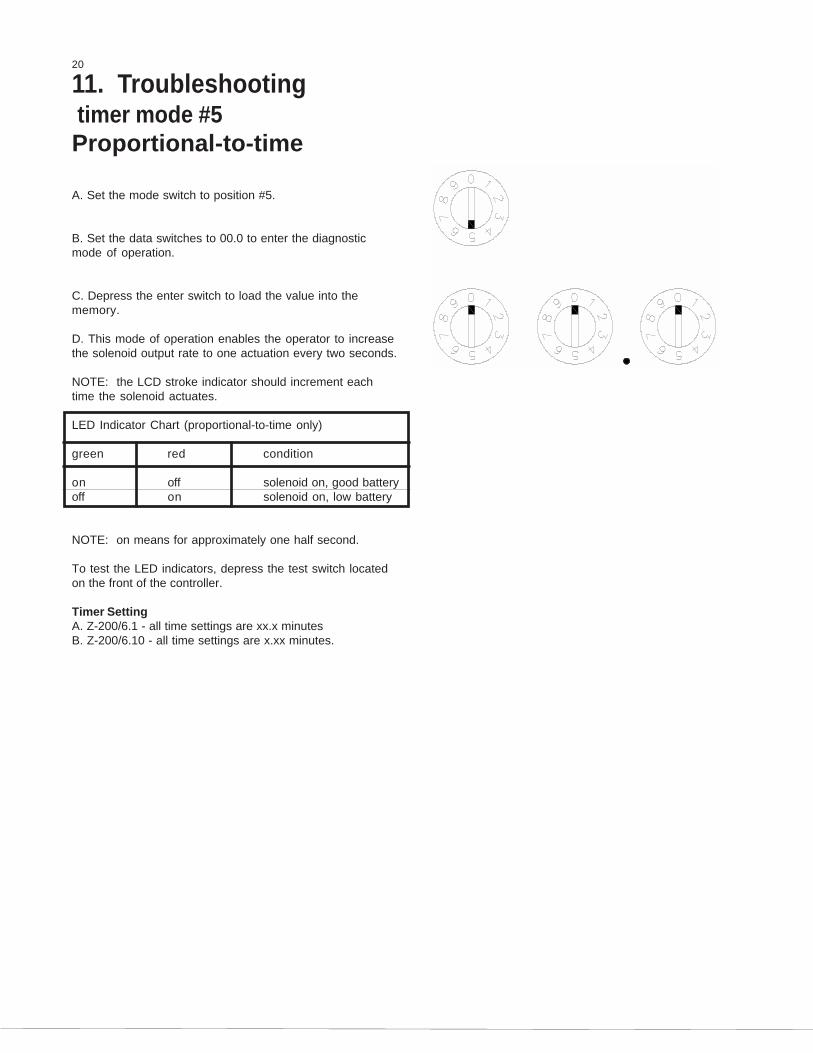
A. Set the mode switch to position #5.
B. Set the data switches to 00.0 to enter the diagnosticmode of operation.
C. Depress the enter switch to load the value into thememory.
D. This mode of operation enables the operator to increasethe solenoid output rate to one actuation every two seconds.
NOTE: the LCD stroke indicator should increment eachtime the solenoid actuates.
LED Indicator Chart (proportional-to-time only)
green red condition
on off solenoid on, good batteryoff on solenoid on, low battery
NOTE: on means for approximately one half second.
To test the LED indicators, depress the test switch locatedon the front of the controller.
Timer SettingA. Z-200/6.1 - all time settings are xx.x minutesB. Z-200/6.10 - all time settings are x.xx minutes.
11. Troubleshooting

DynaPak 2020ARXN 03162005 ATEX Rev.YZ Systems, Inc. • 3101 Pollok Drive • Conroe, Texas • USA • 77303 • P: 936.788.5593 • F: 936.788.5720
21
Proportional-to-flow:run mode #0A. Refer to the controller set-up section in the manual andmake sure the following parameters have been set:1. mode #7 loss of flow input (XX.X min)(X.XX min for Z-200.10)2. mode #6 low flow shut off (XX.X%)3. mode #4 zero calibration (1.0V @ 0% flow)4. mode #3 span calibration (5.0V @ 100 % flow)5. mode #2 initial percentage flow (XX.X%)6. mode #1 initial stroke rate (XX.X min)(X.XX min for Z-200.10)
NOTE: if all parameters have not been entered properly, ared LED will illuminate and stay on and the controller will notstart in run mode position #0 when the enter switch isdepressed.
B. After these inputs have been re-entered, depress enterswitch to start operation.
LED indicator chart (proportional-to-flow mode only)Green Red Conditionon off solenoid on, good batteryoff on solenoid on, low batteryblink off lowflow shut off imposedoff blink loss of flow input alarm
NOTE: on means for approximately one half second. Blinkmeans on for approximately 20 milliseconds.
To test the LED indicators, depress the test switch locatedon the front of the controller.
11. Troubleshooting

22
LCD stroke indicator testA. Set the mode switch to position #5.
B. Set the data switches to 00.0 to enter the diagnosticsmode of operation.
C. Depress the enter switch to load the value into memory.
D. This mode of operation enables the operator to increasethe solenoid output rate to one stroke every two seconds.
E. Unscrew the thumb screws and remove the eightposition terminal strip and cover. This will expose thebattery pack and three position configuration jumper(located in the lower right hand corner of the Z-200 controllerassembly).
F. Set the configuration jumper to the far right positionmarked stroke indicator test.
G. This will cause all six digits to become active or display.Press reset and a display should increment000000,111111, ets., up to 999999 each time the solenoidactuates. When the display reads 999999, the test iscomplete.
NOTE: when the test is complete, move the jumper back tothe factory position (far left).
11. Troubleshooting
configuration jumper
configuration jumperFactory setting for
Setting for stroke indicator test
Factory
ApprovedSystemMutual
Factory
ApprovedSystemMutual

DynaPak 2020ARXN 03162005 ATEX Rev.YZ Systems, Inc. • 3101 Pollok Drive • Conroe, Texas • USA • 77303 • P: 936.788.5593 • F: 936.788.5720
23
Non-linear/linear flow inputThe Z-200 controller is capable of receiving two types of flowoutputs: non-linear and linear.
A. Non-Linear: when using differential pressure transmitterinputs that are not linear with respect to flow, the configura-tion jumper should be in the factory setting to the far leftposition marked non-linear.
B. Linear: when using flow computer type flow inputs thatare linear with respect to flow, the configuration jumpershould be in the middle position marked linear.
11. Troubleshooting
Setting for linear flow input
flow input using the DPTFactory setting for non-linear
Approved
MutualSystem
Factory
Approved
MutualSystem
Factory

24
Diagram #1:DP 2000N pump (assembled)
*DP-3000 HP Pump Seal Kit - P/N D3-0115
P/N B1-0016
P/N B1-0019
P/N B1-0018
Inlet CheckValve Body
P/N C0-0026
*O-Ring (014)P/N A5-1014
Inlet CheckValve Dart
Nut
Lower Diaphragm
Body Bushing
P/N B1-0014
P/N B1-0013
P/N C3-0007
Discharge CheckValve Sleeve
Discharge CheckValve Bushing
Valve SpringDischarge Check
P/N A6-0018
P/N C3-0006
Plunger Return
P/N B1-0051
*Seal
Spring
Housing
P/N A5-1012
20 Micron FilterP/N C4-0022
P/N C3-0008
P/N B1-0020
Inlet ScreenP/N C4-0006
Inlet CheckValve Spring Guide
Inlet CheckValve Spring
*O-Ring (006)P/N A5-1006
*O-Ring (012)
P/N A5-1108*O-Ring (108)
P/N B1-0014
Male Connector1/8"P X 1/8"T
P/N B1-0015Pump Body
P/N B1-0011
Spring Retainer
Plunger AssemblyP/N B1-0052
Bushing
P/N A1-0113
P/N B1-0054
P/N C3-0005
P/N B1-0030
Pneumatic Fitting
Upper Diaphragm
Volume Adjustment
Volume Adjustment
Housing
Spring
Detent
P/N C0-0096Set Screw
DiaphragmP/N A6-0010
P/N C0-0014
Cap Screw(6 Each)
P/N B1-0004Screw AssemblyStroke Adjustment
O-Ring (010)P/N A5-1010
P/N B1-0002
Volume AdjustmentKnob
P/N A6-0106
P/N B1-0059
P/N B1-0012
P/N B1-0071
*DP-2000N Pump Seal Kit - P/N D3-0002
P/N A1-0099

DynaPak 2020ARXN 03162005 ATEX Rev.YZ Systems, Inc. • 3101 Pollok Drive • Conroe, Texas • USA • 77303 • P: 936.788.5593 • F: 936.788.5720
25
Diagram #2:DP 2000N pump (exploded)
*DP-3000 HP Pump Seal Kit - P/N D3-0115
P/N C3-0006
Lower Diaphragm HousingP/N B1-0051
Plunger Assembly
Plunger Return Spring
P/N B1-0052
P/N A6-0010Diaphragm
Stroke Adjustment Screw AssemblyP/N B1-0004
Volume Adjustment Knob
O-Ring (010)P/N A5-1010
P/N B1-0002
P/N A1-0113Pneumatic Fitting
Volume Adjustment Spring
Volume Adjustment Detent
Upper Diaphragm HousingP/N B1-0051
P/N C3-0005
P/N B1-0030
Set ScrewP/N C0-0096
P/N C0-0014
Cap Screw(6 Each)
*O-Ring (012)
P/N B1-0020
P/N C0-0026
Inlet ScreenP/N C4-0006
P/N C3-0008
P/N C4-002220 Micron Filter
Inlet Check Valve Spring
Inlet Check Valve Spring Guide
Nut
Body BushingP/N B1-0016
P/N B1-0018Inlet Check Valve Dart
*O-Ring (006)P/N A5-1006
*O-Ring (014)P/N A5-1014
P/N A5-1012
P/N B1-0014
P/N B1-0013
P/N A5-1108*O-Ring (108)
P/N B1-0015Pump Body
Discharge Check Valve Bushing
P/N B1-0011
Male Connector1/8"P x 1/8"T
P/N A6-0018
P/N B1-0011
P/N C3-0007
Spring Retainer Bushing
Discharge Check Valve Spring
Discharge Check Valve Sleeve
*Seal
P/N A6-0106
P/N B1-0059
P/N B1-0012
P/N B1-0071
*DP-2000N Pump Seal Kit - P/N D3-0002
P/N A1-0099
26
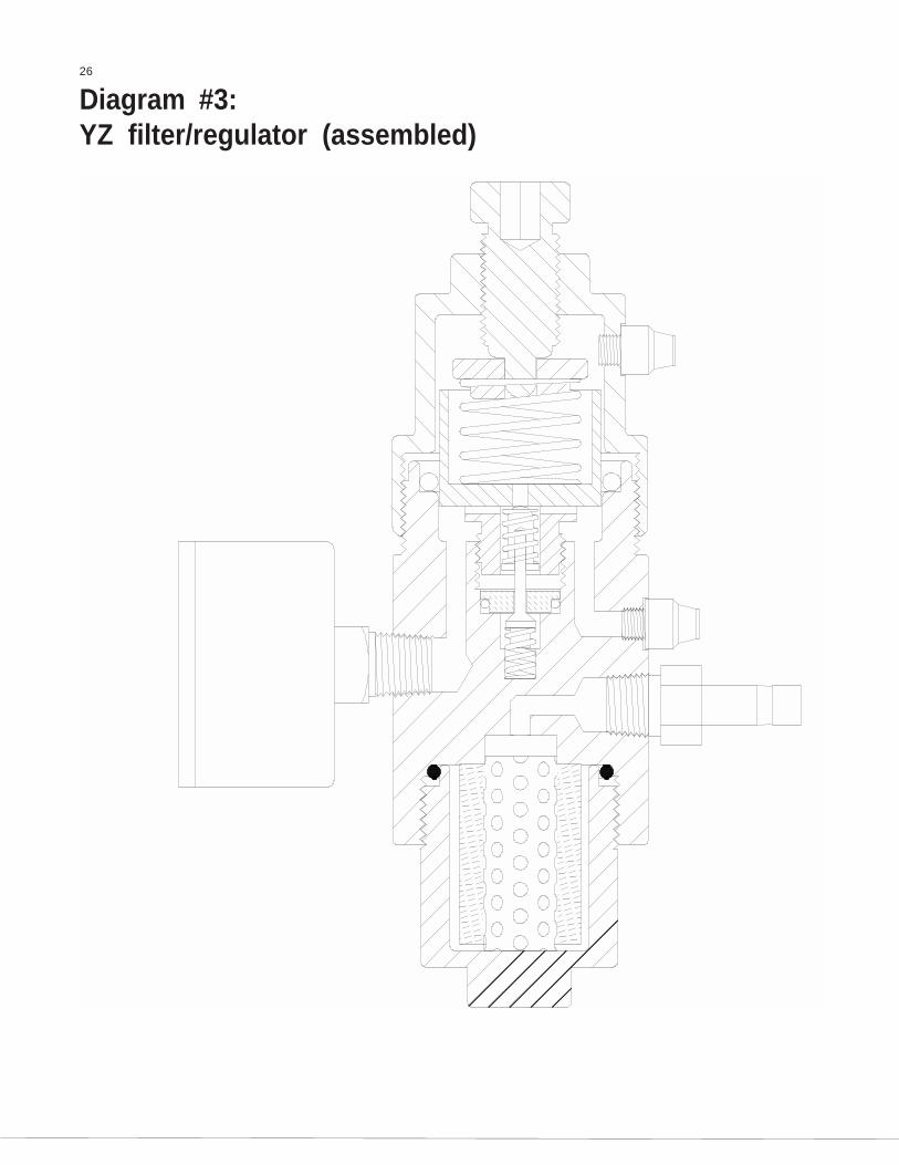
Diagram #3:YZ filter/regulator (assembled)

DynaPak 2020ARXN 03162005 ATEX Rev.YZ Systems, Inc. • 3101 Pollok Drive • Conroe, Texas • USA • 77303 • P: 936.788.5593 • F: 936.788.5720
27
Diagram #4:YZ filter/regulator (exploded)
* Filter/Regulator Repair Kit P/N D3-0003
Pressure Gauge
P/N C3-0009
P/N C3-0011Lower Spring
Lower Dart *A3-0073
O-Ring (012) *
Retaining Nut
P/N A5-1012
Seat *P/N A3-0072
Upper Dart *P/N A3-0071
Upper SpringP/N C3-0010
P/N A3-0070
PistonP/N A3-0069
Piston Spring
Spring CapP/N A3-0068
P/N A3-0067Bonnet
PneumaticFittingP/N A1-0113
P/N A8-0016
Adjustment ScrewP/N A3-0066
O-Ring (120) *
Filter HousingP/N A3-0076
Filter Element *P/N C4-0004
Filter TubeP/N C4-0003
P/N A5-1120
P/N A3-0074Body
Tubing FittingP/N A1-0117
Pneumatic
P/N A1-0113Fitting
O-Ring (214) *P/N A5-1214

28
Diagram #5:Z-200 Controller
Ref. No. Description Part No. Qty.
Z-200/6 Controller Assembly1 1Model Z-200/6.1 F2-0002Model Z-200/6.10 F2-0020
2 Battery Pack E3-2001 13* Stroke Counter Assembly G1-0001 14* Terminal Strip, 6 Position H1-0001 15* BCD Switch E1-0001 46 Face Plate 1
Model Z-200/6.1 A9-3002Model Z-200/6.10 A9-3031
7 Thumb Screw A9-1001 48 Cable Assembly G2-0001 19 Solenoid Valve A4-0001 1
10 Repair Kit* D3-0006 111 Z-65/200 Fuse Replacement Kit D3-0142 1
(2 Fuses Per Kit)
9
8
7
6
5
1
4
3
2
11

DynaPak 2020ARXN 03162005 ATEX Rev.YZ Systems, Inc. • 3101 Pollok Drive • Conroe, Texas • USA • 77303 • P: 936.788.5593 • F: 936.788.5720
29
Diagram #6:Optional LinkPlus
Valve Seat Retainer
Bonnet Stem Assembly
Valve SeatP/N A3-0063
P/N A3-0062
P/N A3-0095
Valve HandleP/N A3-0155
P/N C0-0099
P/N (Varies See Above)Pressure GaugeStainless Steel
Set Screw
Inlet
Rupture Disc (1800 psi)
P/N A3-0083Rupture Disc Retainer
P/N A3-0084
YZ Valve BodyP/N A3-0137
0-1000 PSI (LinkPlus Model No. C1-0005)
0-2000 PSI (LinkPlus Model No. C1-0006)
0-600 PSI (LinkPlus Model No. C1-0004)
Outlet
P/N A8-0007
P/N A8-0012
P/N A8-0011
Pressure Gauge Part Numbers
0-300 PSI (LinkPlus Model No. C1-0003)
0-100 PSI (LinkPlus Model No. C1-0002)P/N A8-0010
P/N A8-0008

30
Diagram #7: Z-200 InstallationNotes/Wiring Control Documentation
System Installation Notes and Recommendations

DynaPak 2020ARXN 03162005 ATEX Rev.YZ Systems, Inc. • 3101 Pollok Drive • Conroe, Texas • USA • 77303 • P: 936.788.5593 • F: 936.788.5720
31
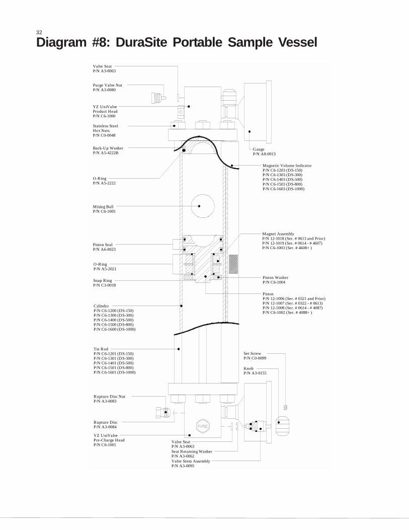
Diagram #8: DuraSite Portable Sample Vessel Instructions
Purpose: The DuraSite Portable Sample Vessel permits theuser to remove a liquid or gas hydrocarbon sample from apipeline or a sampling device. This is accomplished withoutchanging the pressure of the product or exposing it to acontaminant fluid. If properly used and maintained the Dur-aSite will provide many years of safe, accurate and cleansampling.
Use: The DuraSite is a very safe device to use. As with anyequipment dealing with flammable products, it is mandatorythat a good, thorough operator training procedure be estab-lished prior to use.
Typical use of the cylinder would be as follows:
Step 1: (In The Lab) Connect a regulated inert gas supply tothe pre-charge valve. The product valve should be open. Bycarefully controlling the pre-charge valve and the regulator, thecylinder can be slowly charged with pre-charge gas (NOTE:This should be done slowly to prevent slamming the pistondown to the opposite end). The pressure on the pre-chargepressure gauge should be brought to a reading of 10-50 psiabove the expected pressure of the product in the field . Closethe pre-charge valve and disconnect the gas supply. Check thepre-charge valve, relief device, and the pre-charge pressuregauge for leaks. Any leaks should be stopped before continu-ing. The vessel should be placed in a padded carrying case andmade ready for field use.Proceed to EITHER Step 2, or Step 3 asrequired for your application.
STEP 2: FOR COLLECTION OF SAMPLE VIA SPOT SAMPLE ORFROM COMPOSITE ACCUMULATOR VESSEL.
2a: Connect the product end of the pre-charged sample vesselto the product supply.(Sampler product removal valve, or Pipeline sample probe)NOTE: the pre-charge pressure gauge reading should begreater than the product supply pressure reading. If not,repeat Step 1 above.
2b: Once the vessel is connected to the product supply, it isnecessary to vent a small amount of product prior to filling thevessel. This assures fresh product and removes any air or gaswhen dealing with liquids. This can be done by loosening theproduct purge valve a very small amount until the product ispurged. After thorough purging, the product purge valve shouldbe tightened.
2c: The product pressure gauge reading should be 10-50 psibelow the pre-charge pressure gauge reading. By carefullyopening the pre-charge valve, the pressure becomes equal-ized, then begins to drop below the product pressure. The pre-charge valve should be carefully controlled so as to not vent thepre-charge gas too fast.
2d: When the cylinder becomes a maximum of 80% full (seevolume indicator), all valves should be closed. The productconnection is slowly broken in order to vent any trapped product.After vessel removal, all connections should be checked forleaks and the pre-charge and product valve ports capped toprevent leakage.
2e: Pack the DuraSite in appropriate carrying case to meetD.O.T. guideline, with D.O.T. paperwork and transport to lab foranalysis.
STEP 3: FOR DIRECT CONNECTION TOSAMPLER.
3a: Connect the sampler discharge port to the product inlet portto the DuraSite using 1/8" stainless steel tubing.
3b: (Gas sampling) Connect the pre-charge port to theDuraSite to the pipeline for pre-charge pressure (Proceed tostep 3d), or configured like the liquid sample application below.(Step 3c)
3c: (Light sampling) Pre-charge the DuraSite as indicated inStep 1, then install a pressure relief valve to the pre-charge portand open the pre-charge valve on the DuraSite. (The pressurerelief valve should have a relief pressure setting of approxi-mately 100 psi above line pressure.)
3d: Open the product inlet valve of the DuraSite and the purgevalve on the sampler. Next open the purge valve on the productend of the DuraSite and allow product to purge all lines andconnections out.
3e: Close purge valves and begin sample cycle.
3f: At the end of sample cycle, close product inlet valve on theDuraSite and remove the DuraSite. Pack the DuraSite inappropriate carrying case to meet D.O.T. guideline, with D.O.T.paperwork and transport to lab for analysis.
Step 4: (In The Lab) Prior to analysis, the product should bemixed. This is accomplished simply and efficiently by invertingthe cylinder end-over-end, causing the mixing ball to fallthrough the product. Approximately 10-12 trips of the mixing ballthrough the product assures a homogenous solution.
Step 5: The regulated pre-charge gas should be reconnectedto the pre-charge side of the cylinder. The pre-charge gassupply should remain open during analysis.
Step 6: Purging a small amount of product from the vesselremoves unmixed product from the tee, relief device, gauge,etc. The unit can now be connected to a chromatograph andthe product analyzed.
Step 7: After analyzing, the remainder of the product should bedumped and the vessel properly cleaned. Normal cleaning canbe accomplished by rinsing the product end with a petroleumsolvent and flushing with acetone. If a more thorough cleaningis required, the vessel should be disassembled.
WARNING: A portable sample vessel should never be filledto more than 80%. This allows a 20% pre-charge cushion toabsorb thermal expansion of the product.Shipping: Extreme care should be taken when preparing avessel for shipment. Both valves should be capped to preventpossible leakage. The vessel should be placed in asnug-fitting, well-padded and durable case. All applicable DOT
32
Diagram #8: DuraSite Portable Sample Vessel
P/N C6-1002 (Ser. #4088+)
Set ScrewP/N C0-0099
P/N A3-0155Knob
P/N C6-1003 (Ser. #4608+)
Magnet Assembly
Piston
P/N C6-1004Piston Washer
YZ UniValve
P/N A5-4222B
P/N A5-2222
Back-Up Washer
O-Ring
Product Head
Stainless Steel
P/N C6-1000
P/N C0-0048Hex Nuts
Valve SeatP/N A3-0063
Purge Valve NutP/N A3-0080
P/N A8-0013
Magnetic Volume IndicatorP/N C6-1203 (DS-150)P/N C6-1303 (DS-300)P/N C6-1403 (DS-500)P/N C6-1503 (DS-800)P/N C6-1603 (DS-1000)
Gauge
P/N A3-0083
Rupture DiscP/N A3-0084
YZ UniValve
P/N C6-1001Pre-Charge Head
P/N A3-0095Valve Stem AssemblyP/N A3-0062Seat Retaining WasherP/N A3-0063Valve Seat
P/N C6-1200 (DS-150)P/N C6-1300 (DS-300)P/N C6-1400 (DS-500)
P/N C6-1600 (DS-1000)
P/N C6-1301 (DS-300)P/N C6-1401 (DS-500)P/N C6-1501 (DS-800)P/N C6-1601 (DS-1000)
P/N C6-1201 (DS-150)
P/N C6-1500 (DS-800)
Cylinder
Rupture Disc Nut
Tie Rod
Mixing Ball
Snap RingP/N C3-0018
Piston Seal
P/N A5-2021
P/N A6-0023
O-Ring
P/N C6-1005
P/N 12-1008 (Ser. #0614 - #4087)P/N 12-1007 (Ser. #0322 - #0613)
P/N 12-1019 (Ser. #0614 - #4607)
P/N 12-1006 (Ser. #0321 and Prior)
P/N 12-1018 (Ser. #0613 and Prior)

DynaPak 2020ARXN 03162005 ATEX Rev.YZ Systems, Inc. • 3101 Pollok Drive • Conroe, Texas • USA • 77303 • P: 936.788.5593 • F: 936.788.5720
33
13. Rosemount DifferentialPressure Transmitter(DPT):13.1 Theory of Operation: the Rosemount Model 2024Transmitter is a low power differential pressure measuringdevice capable of measuring differential pressures from0 - 250 inches (635 cm) of water and delivering aproportional 1 - 5 volt output. The YZ Model Z-200 controlleris designed to operate the Rosemount 2024 DPT. Bothunits are Factory Mutual (FM) approved for intrinsically safeClass I, Division 1, Groups C, D operation. This allows forthe transmitter to be directly powered by the controller,without the use of barriers, when used in accordance withYZ Industries control document # 103-0431.
13.2 Installationa. Locate the DPT in an area where vibration, shock, andtemperature fluctuation effects are minimal.
b. Mount the DPT directly to the measurement taps or usethe mounting bracket shipped with the transmitter (seediagram below). In either case, mount the DPT at anelevation above or equal to the pipeline measurement taps.
c. Connect the DPT to the Z-200 controller using the wiringkit included with the transmitter. This kit includes YZ'sdrawing #03-0467 which indicates how to connect the DPTand the Z-200.
NOTE: it is recommended that the cable length between theZ-200 and the DPT not exceed 25 feet (7.5 meters).
13.3 Calibration: calibration of the DPT requires the use ofan accurate pressure source and a voltmeter.
a. Check the wiring between the 2024 DPT and the Z-200controller to ensure it is connected correctly.
b. Connect the pressure source to the DPT high pressureport.
MutualSystemApproved
Factory
High Pressure
EqualizationValve
Isolation Valve
Orifice Connection
FLOW
Isolation ValveLow Pressure
SlimLineManifold
Green
Transmitter
Differential
SHD
White
Red
Black
(DPT)
Pressure
Maximum Pressure 2000 PSIA

34
c. Connect the voltmeter positive lead to the DPT signalterminal and the voltmeter negative lead to the DPT commonterminal.
d. Turn the mode switch on the Z-200 controller to position 4.
e. While applying the equivalent of 0" (0 cm) differentialpressure to the transmitter, turn the DPT "Zero" adjustmentscrew until the transmitter output reads 1.00 volts.
f. Press the test/enter button on the Z-200 to set thecontroller's zero reference.
g. Turn the mode switch on the Z-200 controller to position 3.
h. While applying the equivalent of maximum flow differentialpressure to the transmitter, example 100" (254 cm) waterdifferential, turn the span adjustment screw until the outputreads 5.00 volts.
i. Press the test/enter button on the Z-200 to set thecontroller's span reference.
j. Repeat steps d. through j., readjusting the DPT zero andspan as necessary.
k. Return the mode switch on the Z-200 controller to position9. Refer to Section 8.2 to set the system input parametersbefore starting system operation.
NOTE: mode switch must be in position 3 or 4 to readtransmitter output voltage.
13. Rosemount DifferentialPressure Transmitter (DPT):
Voltmeter
2024 DPTRosemount
Signal
Common

DynaPak 2020ARXN 03162005 ATEX Rev.YZ Systems, Inc. • 3101 Pollok Drive • Conroe, Texas • USA • 77303 • P: 936.788.5593 • F: 936.788.5720
35
Notes:
3101 Pollok Drive
Conroe, Texas 77303
P: 936.788.5593
F: 936.788.5720
Web: www.yzsystems.com
YZ Systems, Inc. represents and warrants that for a period of 3 years from receipt of the product: (1) the product will be free from defects in materials andworkmanship; and (2) the product will perform substantially in accordance with product manuals, literature, or documentation. Any written or oral information or advicegiven by YZ representatives, agents, or employees will in no way increase the scope of this warranty. If the product fails to comply with the warranty set forth herein,YZ's entire liability and the customer's exclusive remedy will be replacement of the product(s) or, at YZ's option, YZ's reasonable effort to make the product meetthe warranty set forth herein. YZ disclaims all other warranties, either expressed or implied, including but not limited to, implied warranties or merchantabilityand fitness for a particular purpose, with respect to the product. This limited warranty gives you specific legal rights. You may have others, which vary fromstate to state. These remedies are not available outside of the United States and Canada. In no event shall YZ or its suppliers be liable for any damages whatsoever(including, without limitation, damages for loss of profits, business interruption, loss of information, or other pecuniary loss) arising out of the use of or inability touse the product, even if YZ has been advised of the possibility of such damages. Information contained in this document is subject to change without notice anddoes not represent a commitment on the part of YZ Systems, Inc. All prices quoted are in U.S. dollars, F.O.B. Snyder, Texas. NJEX is a trademark of YZ Systems,Inc. All other product names and/or registered trademarks are the property of their respective holders. YZ support services are subject to YZ's then-current prices,terms, and conditions, which are subject to change without notice. All prices and specifications, if published, are subject to change without notice.