dynamics parameters identification of rigid-body...
TRANSCRIPT

Dynamics Parameters Identification of Rigid-BodyManipulators through Natural oscillations
Rodrigo S. Jamisola, Jr.t, Elme] p. Dadiost, and Marcelo H. Ang, Jr.*
Abstract-This work will present an experimental procedurein identifying the moments of inertia, mass, and center of massof a rigid-body manipulator through natural oscillations. Basedon the response of the manipulator, the values of the dynamicsparameters to be identified are adjusted in such a way thatthe desired natural oscillation is achieved. The experimentsto be performed on a manipulator under torque control arecomposed of two sets: mass and center of mass identification.and moments of inertia identification. The first set of experimentswill use an openJoop control, such that the natural oscillation isminimized. The second set of experiments will use a proportionalcontrol, such that the square of the natural oscillation is equalto the proportional gain. Thus each set of experiments has awell.defined objective function such that it can be treated asan optimization computation. The correct dynamics parametersare idenffied when the desired objective function is achieved.The proposed dynamics identification method is analyzed anda theorem is presented to support the claims presented in thiswork, together with simulation resul8.
Index Terms-moment of inertia, mass, center of mass, identi-fication experiment, dynamics model, natural oscillation, torquecontrol
I. INTRODUCTION
A full dynamics control of a robot manipulator can onlybe achieved with accurate information on the manipulator'sdynamics parameters. A very good performance in full dy-namics simultaneous force and motion control shown in [l]was achieved because the manipulator dynamics were properlymodeled and identified. The accuracy of dynamics modelinglies heavily on accurate values of the manipulator's dynamicsparameters, namely, the moments of inertia, mass, and centerof mass. Although some robot manufacturers do provideinformation on mass and center of mass parameters l2l, themoments of inertia are not provided. One possible hesitationin providing the inertia values by manufacturers is the factthat at best, they only provide inertia values based on thetype of material used and CAD drawing of the physicalsystem. However, values derived through this method canbe inadequate because of other factors like gear ratio andmotor inertia, which could offset the true values of the inertiaparameters.
But even if all the dynamics parameters are provided by amanufacturer, from the point of view of full dynamics control,
, tDept. of Electronics and Communications Engineering and
+Dept. of Manufacturing Engineering and Management, O" LaSalle University - Manila, 2401 Taft Ave, 1004 Manila, philippines
{ rod r i go . j am iso la , e tme r . dad ios }od l su . edu . ph .*Dept. of Mechanical Engineering, National University of Singapore, 21
Lower Kent Ridge Road, Singapore 1 19077 mpeangh@nus . edu. sg.This work is supported by the University Research Council of De La Salle
University - Manila.
it would be good to verify the accurateness of the given valuesespecially when the given manipulator has achieved thousandsof hours of operation. Thus, an experimental procedure toidentify the mass, center of mass, and inertia values can bemore appropriate.
This work will propose an experimental procedure in iden-tifying mass, center of mass, and inertia parameters throughnatural oscillation. The experiment sets the manipulator toachieve a linear second-order system response and its os-cillation is measured. A well-defined value of the desirednatural oscillation transforms the identification experimentinto an optimization computation. The period of oscillation isminimized in the mass and center of mass identification withthe manipulator under open-loop torque control. While in theinertia identification, the square of the period of oscillationis equal to the proportional gain, with the manipulator underproportional torque control.
There are several studies in inertia parameter identificationdesigned to accurately model and control a physical system.Among such studies include a moment of inertia identificationfor mechatronic systems with limited strokes [3] in utilizingperiodic position reference input identification ofinertia basedon the time average of the product of torque reference inputand motor position. This study showed the moment of inertiaerror is within *25Vo. On tracking a desired trajectory andnoting the error response, inertia parameters are identifiedusing adaptive feedback control [4] where angular velocitytracking are observed and inertia parameters are changed,while a globally convergent adaptive tracking of angularvelocity is shown in [5]. In other studies, least squares errorin the response is used in inertial and friction parametersidentification for excavator arms [6]. It is also used to identifyinertias of loaded and unloaded rigid bodies for test facilities[7], and in another experimental set up [8].
Inertias that are dependent on the same joint variables,and is also referred to as the minimal linear combinations ofthe inertia parameters [9], can be combined to form lumpedinertias. This inertia model has been shown even in an earlierwork on a complete mathematical model of a manipulator [10].In most cases lumped inertias, instead of individual inertias,are identified. This is because lumped inertias are easier toidentify.
A similar work that identified lumped inertias throughnatural oscillation is shown in [11]. The shown full dynamicsidentification method was the foundation in a successful imple-mentation of a mobile manipulator [1] performing an aircraftcanopy polishing at a controlled normal force of 10 N. Thebiggest challenge in implementing the dynamics identification
10
in [11] is its need for a simplified symbolic model in order to
identify the lumped inertias. Deriving the simplified symbolic
model can become very computationally expensive when the
number of degrees of freedom of the manipulator increases.
In addition. the mass and'Center of mass were not identified
and were assumed as given. r
This work differs from [11] in the sense that the identifi-
cation procedure proposed in this work does not require the
simplified symbolic model because the individual inertias are
identified, and not the lumped inertias. The mass and center
of mass are individually identified as well. These two points
comprise the major contributions of this work.
More recent identification procedures of manipulator arm
dynamics include the use of torque data flzl, floating-base
motion dynamics [3], iterative learning [14], neural network
aided identification [15], set membership uncertainty [16],and simultaneous identification and control [17]. Identification
procedures that are more robot specific include tl8l, tl9l,
l2}l, I2ll. Some examples of identification procedures for
humanoid robot dynamics used neural network [22], and
fuzzy-stochastic functor machine [23]. Recent humanoid robot
modeling and control include fuzzy neural network [24]'global dynamics [25], and ground interaction control [26].
In most identification procedures the identification experi-
ment is dependent on minimizing the least squares error based
the robot response to a predefined path which excites the
dynamics parameters. The controller used in the experimentalprocedures is the same confioller that were used in the actual
robot control. This approach can be at a disadvantage because
characterizing a path that isolates the dynamics contribution
of each parameter can be hard to find. Thus in some cases,
the accurateness of each individual physical parameter values
are at times compromised.
The experimental procedure proposed in this work make
use of an independent controller and is dependent on each
link achieving natural oscillation. The estimated values of
the excited physical parameter can be verified by noting the
change in the period of oscillation based on its predetermined
value. The parameter estimates are adjusted such that the
desired ncrin'l ^r -^'-;;l .o'iiiariu, or a glven lmk is achieved.
This isolates each individual physical parameter estimate to the
system response.
This work will propose an experimental procedure, based
on natural oscillation, to identify the individual moment of
inertia, mass, and center of mass parameters of rigid-body ma-
nipulators. The objective it to make the rigid-body manipulator
achieve linear second-order response such that a desired value
of its natural oscillation is known. When the desired natural
oscillation is reached, the correct parameters are found. This
work is aimed at providing an alternative in dynamics iden-
tification methods that is easily implementable, that identifies
individual dynamics parameters, and with comparably accurate
results. A theorem is presented to support the mathematical
principles behind the experimental procedure together with
experimental results.
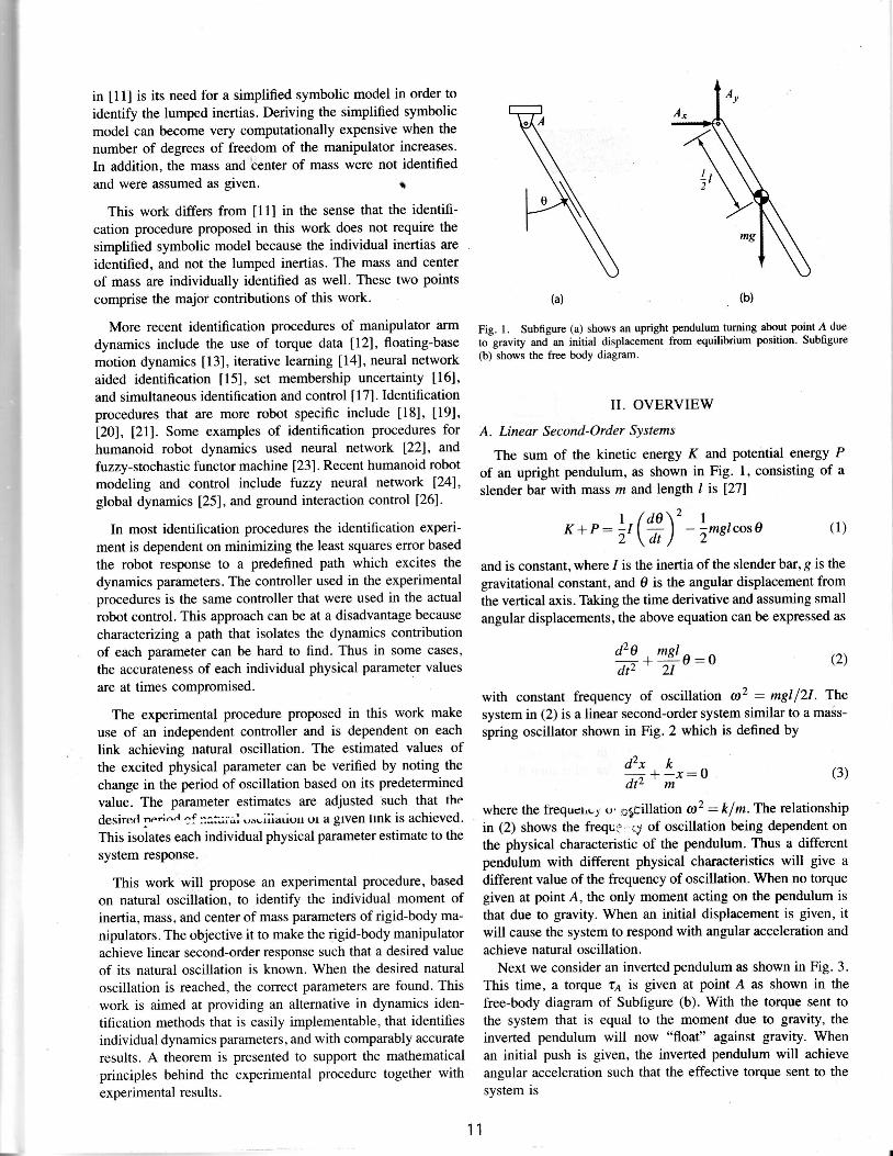
Fig. l. Subfigure (a) shows an upright pendulum nrming about point A due
to gravity and an initial displacement from equilibrium position. Subfigure(b) shows the free body diagram.
II. OVERVIEW
A. Linear Second-Order SYstems
The sum of the kinetic energy K and potential energy P
of an upright pendulum, as shown in Fig' l, consisting of a
slender bar with mass tn and length I is l27l
and is constant, where 1 is the inertia of the slender bar, g is the
gravitational constant, and 0 is the angular displacement from
the vertical axis. Thking the time derivative and assuming small
angular displacements, the above equation can be expressed as
**!s:o (2)dtz 2l
-
with constant frequency of oscillation o)2 : mglf2l . The
syst€m in (2) is a linear second-order system similar to a mass-
spring oscillator shown in Fig. 2 which is defined by
(1 " +k r :o (3 )clt. m
where the frequct,ug o' pgcillation a2 : k I m. The relationship
in (2) shows the frequ3' ey of oscillation being dependent on
the physical characteristic of the pendulum. Thus a different
pendulum with different physical characteristics will give a
different value of the frequency of oscillation. When no torquegiven at point A, the only moment acting on the pendulum is
that due to gravity. When an initial displacernent is given, it
will cause the system to respond with angular acceleration and
achieve natural oscillation.Next we consider an inverted pendulum as shown in Fig. 3.
This time, a torque t1 is given at point A as shown in thefree-body diagram of Subfigure (b). With the torque sent tothe system that is equal to the moment due to gravity, theinverted pendulum will now "float" against gravity. Whenan initial push is given, the inverted pendulum will achieveangular acceleration such that the effective torque sent to thesystem is
11
(b)(a)
| /d0 \2 IK + P : ; , \ ; ) - l m s t c o s o ( r )

. . 70 - l =ko | : 0 .
I(7)
where fko: ct2. Therefore, the inertia is correctly modeledwhen the frequency of oscillation az : kp.
D. Multi-Link Rigid-Body Dynamics : : !
The general case of the multi-linked rigid body dynalrtiis ofa manipulator will be presented. The torque to be sent to eachjoint of the robot is computed by taking the kinetic eneigy'Kand potentihl energy P and solving the Lagt'ange'equdtibn ofT : K * P [ 2 8 1 ; ' : ' r r
Fig.2. A linear second-order system: spring-mass oscillator.
r (a) , (b)
!ig. f. Subfigure (a) shqws an inverte{ pendulum, Subfigure (b) shows thefree body diagram such that the gravitational compensaiion is sent to thesystem all the time which results into a systep that is floating against gravity.
. . l :76: I0 +
lmglsin9, (4)
that is, the effective torque seiit ar poim A is the sum ofthe given inittal'push'that resulted into an acceleration andthe torque sent to balance off gravity. An oscillation occurs'because the total enexgy is in the process of being convertedfrom a purely potential energy to a ptrrely kinetic energy, andvice versa.
B. Mass and Center of Mass ldentification
A torque control in (4) will equate the torque sent to thephysical system to the torque sent to control it such that,
. . I I .ra: I6 * izglsin 0 : iu+ ;ngisine (5)
L L
where i denotes the approximation of the actual physicalsystem. Setting an open-loop control, u : 0, and assumingsmall angular displacements that is around *15 degrees, (5)becomes
.. ml -fiti ^0 + -:1f g0:o (6)
which is a linear second-order system where co2 : (mt -nri )g l2I. The minimum crr correspond s to ml : rhi.
| :C, Moment of Inertia ldentification
A proportional gain is set to (5) such.that the iontrolequation is expressed as u: -k70 where kp:is the propor-tional gain. Assuming that the, gravitational term was corr€ctlymodeled, (5) can be expressed as a linear second-order svstem
' , ' (8)
such the joint torgug vector is expressed,as ,i , ,i:, , , , r, 1 . 1 . ,
r :A (q )0+c (q ,Q)+g (q ) . , , : , , , . , ( g )
The symbol A(q) is the joinrspace inertia matrix, c(q, q) is theCoriolis and centrifugdl forces vector, g(q) is the giavitationaltefms vector, and ri,Q,q are the joint spaib acieleraiion,velocity, artd displacement. The' control equatibn ii givenr'aslzel
u : {d , k,(Q - qd) - kp(q- qd) (10)
where ko is the proportional gain, ku is the'derivatiVe gaih,and the isubscript d denotes':desired value!. iir,aaaititin,toassuming small displacements' during ideirtifi cation prticediiib,velocity for each link is assumed'small such'thal Cofiolisand centrifugal forces are less dorninanticomparbd to thegtavitatioiral forces, and the inertia matfix.'These assumptionswould lead to a linear-second order system that is equivalentto the single degree-of-freedom (DOF) case.
In U U, it is shown that the lumped inertia terms found in theinertia matrix A(q) are the same terms found in Coriolis andcentrifugal forces vector c(q,8). Once all the lumped inertiaterms are identified in A(q), all the inertia terms ar€ alreadyfound.
III. THE PROPOSED DYNAMICS IDENTIFICATIONMETHOD
In this section we will show a mathematical proof ofthe proposed method to support the claims in this work inidentifying mass, center of mass, and moment of inertia. Inaddition, corresp-onding algorithms will be sfown.
A. Mass and Center of Mass Identification.,
Given a physical systern such that each link is influenced bygravitational force, mass and center of mass ean be'identifiedby letting the system achieve natural oscillationrthrough'theforce of gravity. It is ,assurned that the links move at smallangular displacements around *15 degrees away'from zerogravity. axis. Fricdon contribution is disregarded in this workand r.vill be.addressed in the future .
d lar l a r- l - l _ - - ? .
at l0q1l 0q,- " ' .
1'2

Theorem 1; A multi-link rigid manipulator with revolutejoints is under torque control and is influenced by gravitationalforce, Its minimum frequency of oscillation o is achievedwhen the estimated physical parameter values in the mathe-matical model are closest to the values in the physical system.
Proof: Case I. Single Degree-of-Freedom. Eqrpting thetorque between the physical system and the mathematicalmodel results in
t : t6+s(0) : iu+E(O) , ( l l )
where the control equation u : 6a - k"(6 - Ot - kp@ - ei.Setting z =0 results into open-loop control such that
6*s(o) :3(o) - r .
the natural frequency of oscillation and ko is the proportionalgain.
Proof: Case I. Single Degree-of-Freedom. Equating thetorque between the physical sys0em and the mathematicalmodel.
r : 16 +8(e) : iu+E(0), (17)
The proportional control is set to u: -kog. and. the rest ofthe control terms are set to zero, &u :0 and 0a - 0d: 0a:0.Because the gravity has no influence or is correctly modeled,the equation becomes
. . i0 I =ko0 :0 .
I(18)
linear second-order system [30] such(12) This is an undamPedthat,
Because of relatively small angular displacements, (12) can beconsidered as an undamped linear second-order system [30]where
a2 : f(s@) -g(0)). (13)
Because 1 is constant, co is minimum when g(0) : g(0).
Case II. Multiple Degree-of-Freedom. The torques sentto the physical system and the mathematical model are equaland can be expressed as,
r :A(0)6*c(0 ,d) +s(e) : A(e)o+e(0 ,e) +g(0) . (14)
With relatively small joint velocities, Coriolis and centrifugalforces are less dominant and are ignored. With small angulardisplacements, gravitational terms can be considered linear.Setting the control equation u:0 results into
0 + r(e)-1 l(g(e) - E(g))1. (ls)
With the small angular displacement A(0) can be consideredconstant. As the correct parameter values are approached,the system becomes decoupled such that each link can beindependently considered as second-order undamped linearsystem [30] where
a2: f (s (o ) -g (0) ) . (16)
The minimum ar is achieved when C(0): E(0). I
B. Moment of Inertia ldentification
Given a physical system with its gravitational model cor-rectly compensated (or is independent of the gravitationaleffect), the inertia parameters can be identified by lettingthe system achieve its natural frequency of oscillation. Theinertia'values will be adjusted until the desired frequencyresponse is achieved. The following corollary follows thetheorem presented above.
Corollary 1; A rigid manipulator under proportional torquecontrol is not influenced by gravity. The correct values of linkinertia parameters are identified when crl' : kp where al is
" i -0r-:
ikp.(1e)
When i:1, then kp: a2.
Case II. Multiple Degree-of-Frcedom. The torques sentto both the physical system and the mathematical model areequal and expressed as,
c : A(0)0 *c(9,6) +g(e) : A(e)u+e(0,e) +E(0). (20)
Setting the proportional control to u: -kr_O an{ the rest ofthe control terms are set to zero, ku :0 and 0a - 0d: 0a:0With slow velocities the Coriolis and centrifugal terms are lessdominant and can be ignored. And because gravity has noinfluence or is correctlv modeled.
d +.n (e)-14(g)kpo : 0. (2r)
As the system approaches the correct parameter values, itbecomes decoupled such that each link can be independentlyconsidered as second-order undamped linear system [30]where
a2: A(0)-ta1e;no. (22)
The case of A(e) : A(0) results in @2 :kp. I
C. The Algorithm
The algorithm for identifying mass, center of mass, andmoment of inertia through natural oscillation is presented inthis subsection. For mass and center of mass. the identificationprocedure is the following.
1) Select initially large values for the mass fr, and centerof mass I to initialize the dynamics parameters of themulti-link rigid body.
2) For each of the joint, send the torque c corresponding tothe Coriolis and centrifugal forces and the gravitationalterms.
3) Let each link oscillate from a predefined initial displace-ment, to help create consistency of results. The systemwill start to oscillate at a certain frequency co.
4) Measure the frequency of oscillation or.
13

, r - {
3-DOF
Fig. 4. The frame assignment for I-DOF,2-DOF, and 3-DOF manipulators.
5) Adjust the values of the dynamics parameters fi, and 7to minimize the frequency of oscillation ar.
6) Repeat Steps 2-5 until the minimum frequency of oscil-lation ar is found such that its corresponding fit, and fare the best estimates.
In identifying moments of inenia i, the same algorithmas stated above will be used, except that f is the unknownparameter instead of ft and L Then instead of minimizingo, the corresponding objective value of the frequency ofoscillation will be a2 : kp.
The large values of the initial dynamics parameters arerecommended to have an initially large solution space toexplore. A predefined initial displacement is used to createconsistent results in measuring the frequency of oscillation.The predefined value of this initial displacement should beabout *15 degrees and with alternating opposite signs onconsecutive joints. This setup will help minimize the displace-ment for each joint such that the assumption on linearity ofthe manipulator response will hold. In addition, this will alsominimize the contribution of Coriolis and centrifugal forcessuch that the accumulated displacement of each joint remainssmall.
To measure the frequency of oscillation crr, normally thenumber of periods of oscillation is counted within a predefined
number of update cycles. An incremental step is performed
within the search space of the dynamics parameters to find
the combination of values that correspond to the desired al.The dimension of the search space increases as the number ofdynamics parameters to be identified increases. Incrementallychanging the values of the dynamic parameters and measuring
the corresponding frequency of oscillation are repeatedly per-
formed. For higher degrees of freedom, it is highly possible
that the identified parameters will result in a combination ofpossible range of values. Each of the possible combinationscan be checked later against the robot response in the actualmanipulator control.
)
,-*
IV. RESULTS AND ANALYSIS
Simulations are performed to test the proposed algorithmin identifying the dynamics parameters of l-,2-, and 3-DOFsmanipulators. Open dynamics engine (ODE), an OpenGLprogam integrated with C code, is used as the simulationplatform. This simulation platform requires the actual phys-ical model for the system to move in a virtual world. Thedynamics parameters are then provided to create a model forthe simulation. Then the conesponding torques are sent to thejoints using estimated dynarnics parameter values.
In this section, the range of estimated values correspondingto the desired at will be presented for each of the simulatedmanipulator. The frame assignment is shown in Fig 4. Thesimplified symbolic dynamics model of l-,2-, and 3-DOFsmanipulators shown here are expressed in terms of masses andcenter, including the inertias. Corresponding mass factors areused to vary the possible range of values for the mass, centerof mass, and inertia parameters. The following symbol sim-plifications are used Si...n: sin(lf Q) and Cr...n: cos(lf 0;).
A. One Degree of Freedom
The simplest case of I-DOF is shown to test the sensitivityof the system to numerical errors. Given a mass rzr and linklength L, a mass factor fm1 and fm2 are multiplied to thegravitational and inertial terms, respectively.
It fm, ImrLz' )Bt : fru i mlgL 51.
(23)
An initial 15 degrees displacement was used to perturb thesystem and let it achieve natural oscillation. The results areshown in Table I for the mass and center of mass and Table IIfor the moment of inertia.
TABLE IMAss AND CENTER OF MASS IDENTIFICATION FOR 1-DOF
1.0201.0101.0051.004l 003t.oo21.0011.0000.999
8.76.95 .85.55 . 14.84 )4 .1
(falls under gravity)
The correct values of the dynamics parameters correspondto fmy: fmz: 1.00. Table I shows consistently that asthe estimated parameters start from large values and de-crease towards the correct values, the frequency of oscillationdecreases. And at 0.001 difference of the mass factor, adifference in the frequency of oscillation is achieved. Theminimum frequency of oscillation is shown to be 4.1 periodsper 5,000 update cycles. A mass factor f 6:0.999 will causethe system to fall due to gravitational force. Table Il showsconsistently that as the mass factor increases, that is, the inertiaestimates become larger than the actual values, the frequencyof oscillation increases. It can be safely assumed that the
14

difference in the frequency of oscillation is more elaboratewhen the mass factor changes to around 5Vo.ltis also possible
to increase the number of sampling updates in order to makemore elaborate differences in the frequency of oscillation. An
analytical sensitivity analysis on the mass and center of mass
identification effor as compared to the inertia identificationerror will be shown after this section.
B. Two Degrees of Freedom ,
The symbolic form of the components of inertia A(0),
Coriolis and centrifugal forces c(9, 0) and gravitational termsg(0) of the 2-DOFs manipulator is shown in (24).
TABLE IIIMAss AND CENTER OF MASS IDENTIFICATION FOR 2-DOFS
at
fmt' . f*z Link I, Link 2
5.44.74.54.54.4r ' , )4.03.6
( falls under gravity )
TABLE ryINERTIA IDENTIFICATION FOR 2-DOFS
at
f^2, f^t Link 1. Link 2
TABLE IIINERTTA IDENTIFICATIoN FoR 1-DOF
f*z Link 1
1.00l . 0 1t.o21.031.041.051.061.071.081.091 . 1 0
35.5035.5736.0036.0036.1036.5036.6236.6037.0037.0037. t3
1.0051.0041.0031.0021.0011.000o.9990.998
1.01t.o21.03t.o41.051.061.071.081.091 t0
35.6136.0036.0036.1436.5036.5036.6637.0037.0037.17
An fmalmll? + fmtmzl](t +Cz)Atz : A21 : fm3m2t?11+ lC21Azz : fm3\m2L2cr -fm3lm2Lz4z(24t*qz)Sz
c2 : frylm2LzS2Qlsr : f ̂ t (L*t -f m2)Lgs1* fm2lm2LgSp
(24)
Ez : fm2)m2LgSp
In the symbolic model shown, the mathematical model
of the inertias were simplified such that only the principal
moment of inertia about the joint axis is considered. The
other two principal moments of inertia and all the Broducts of
inertia were assumed zero. However, in the simulation model
this is not true. as the ODE simulation mimics the real-worldphysical system these values can only be assigned relatively
small values and not completely zeros.For each of the lumped inertia parameters, mass factors /z 1,
fmz, fmz, and fma are used. Note that the dynamics model
can be identified:jndividually without the lumped symbolic
model. However, the value of the lumped model only served
to show the limits on the products of the identified parameters.
In a sense it is the lumped model that is identified such that
any values of m1 and L would suffice to model the dynamicsparameters as long as the product of their values correspondingto the actual physical model and is correct to within a desired
accuracy. This precision defines the range ofpossible identified
values.Table III shows the experimental results for 5900 updates
of a two degrees of freedom robot with varying mass factors
f6 and f*2.The frequency of oscillation is recorded for the
different values of the mass factors. The robot falls under the
influence of gravity when the mass factors are 0.002 below the
assigned physical mass factor of 1.0. The minimum frequencyof oscillation applies when all mass factors are 0.001 below
1.0. The frequencies of oscillations for both links decreasedaccordingly as estimated values decreased towards the actualphysical values.
Table IV shows the experimental results for 20000 updatesof a two degrees of freedom robot with two mass factors fm3and fma being varied. The frequency of osr:illation is recordedfor the different values of the mass factors. A mass factor of1.0 corresponds to the correct natural frequency a2 : kp. Thefrequencies of oscillations for both links increased accordinglyas the mass factor were increased. Again around 5Vo differencein the mass factor created an elaborate difference in therecorded period of oscillation.
15,l-
A n :
A n :
.f ry * (* t * 4m2 * 7 m3) I? + f m5 (mz I 2m3) L2 c2+ fmam3L2(Q+Czz)
t2, : 1m6 \ (mz * 4mz)L2 + f m5l(m2 + 2ry) I? c2* fmalm3L2(2Cz*Czz) t
A31 : f ma fm3L2 (Z + 3Ct * 3Czz)A32: fmafm3L2(2+3q)
f*sl@z + 4ry) L2 * f mq3mtL2 cz
fmalryL2- f ms L @z * 2ry) L2 Q2(2h + 4z) sz
- J ma )ryl? (42 Q4 r * 2Q2 i q) s3+ @z+ Qt)Qh I q2+ 4z)szz)
"f*si@z+2ry)L24ls2-t f ma lry L2 (- qz (zq, * 2Qz * qz) s t
*4?szt)7m4 )ryr2 ((4 r * 4z)z sz + 47szz). fq i@r *2(m2*ry))Lgs1
+ fm2|(m2-t2m3)LgSpt fm3)m3LgSp3
f*zi@z*2m3)Lgsp
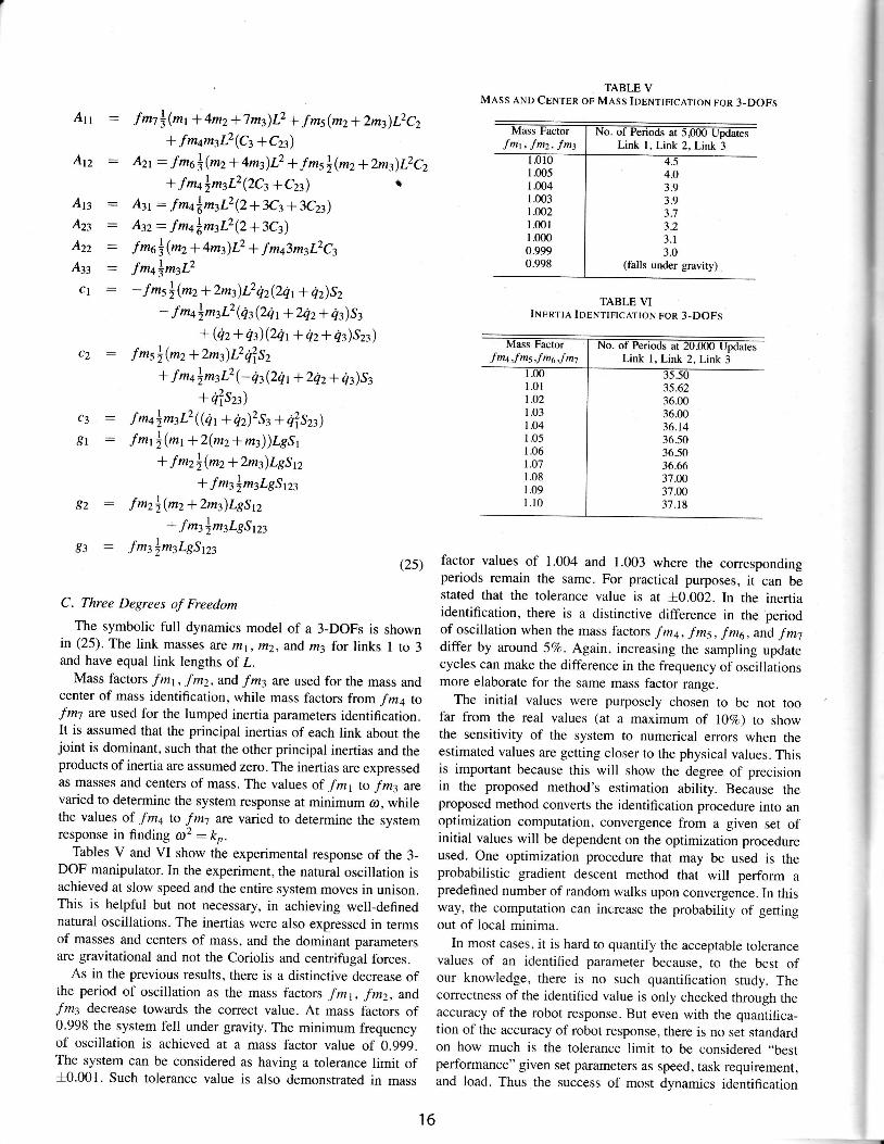
TABLE VMAss AND CENTER oF MAss IDENTIFICATIoN FoR 3.DoFs
fm1, fm2, fm3^
AnAzzAzzAn
c l
1.005l.()ol1.0031.0021.00r1.000o.9990.998
4.O3.93.95 - t
3.23 .13.0
(falls under gravity)
c Z :
g 2 :
* fm3)m3LgSp3g3 : fm3)m3LgSp3
(2s)
C. Three Degrees of Freedom
The symbolic full dynamics model of a 3-DOFs is shownin (25). The link masses are mr,m2,andm3 for l inks I to 3and have equal link lengths of I-
Mass factors fmt, fmz, and fm3 are used for the mass andcenter of mass identification, while mass factors from fma tofm7 are used for the lumped inertia parameters identification.It is assumed that the principal inertias of each link about thejoint is dominant, such that the other principal inertias and theproducts of inertia are assumed zero. The inertias are expressedas masses and centers of mass. The values of fm1 to fm3 arevaried to determine the system response at minimum a;, whilethe values of fma to f-m7 are varied to determine the systemresponse in finding a2 : kp.
Tables V and VI show the experimental response of the 3-DOF manipulator. In the experiment, the natural oscillation isachieved at slow speed and the entire system moves in unison.This is helpful but not necessary, in achieving well-definednatural oscillations. The inertias were also expressed in termsof masses and centers of mass, and the dominant parametersare gravitational and not the Coriolis and centrifugal forces.
As in the previous results, there is a distinctive decrease ofthe period of oscillation as the mass factors fm1, fm2, andfm3 decrease towards the correct value. At mass factors of0.998 the system fell under gravity. The minimum frequencyof oscillation is achieved at a mass factor value of 0.999.The system can be considered as having a tolerance limit of+0.001. Such tolerance value is also demonstrated in mass
TABLE VIINERTIA IDENTTFtcATtoN FoR 3-DOFs
atfma,f m5,f m6Jm7 Link I, Link 2,Lir/r- 3
1 .01r.o21.031.041.051.06l 0 71.081.091 . 1 0
35.6236.0036.0036.t436.5036.5036.663't.N37.0037.18
factor values of 1.004 and 1.003 where the correspondingperiods remain the same. For practical purposes, it can bestated that the tolerance value is at i0.002. In the inertiaidentification, there is a distinctive difference in the periodof oscillation when the mass factors f mq, -f ms, f m6, and f m7differ by around 5Vo. Again, increasing the sampling updatecycles can make the difference in the frequency of oscillationsmore elaborate for the same mass factor range.
The initial values were purposely chosen to be not toofar from the real values (at a maximum of l\Vo) to showthe sensitivity of the system to numerical errors when theestimated values are getting closer to the physical values. Thisis important because this will show the degree of precisionin the proposed method's estimation ability. Because theproposed method converts the identification procedure into anoptimization computation, convergence from a given set ofinitial values will be dependent on the optimization procedureused. One optimization procedure that may be used is theprobabilistic gradient descent method that will perform apredefined number of random walks upon convergence. In thisway, the computation can increase the probability of gettingout of local minima.
In most cases, it is hard to quantify the acceptable tolerancevalues of an identified parameter because, to the best ofour knowledge, there is no such quantification study. Thecorrectness of the identified value is only checked through theaccuracy of the robot response. But even with the quantifica_tion of the accuracy of robot response, there is no set standardon how much is the tolerance limit to be considered ,.best
performance" given set parameters as speed, task requirement,and load. Thus the success of most dynamics identification
! J
8 r :
16

method normally is based on response of the manipulatorwhere the identification is being implemented. And this isdependent on what type of task the manipulator is requiredto perform, and is generally not applicable to all systems.
V. SpNstrwtrv ANaI-vsIs r
Identifying the inertia parameters, together with the massand center of mass, can create different errors in the torqueresponse due to inaccuracy in.the identified parameters. Thissection will show sensitivity to parameter errors in terms ofgravitational terms as compared to inertial terms, and howboth terms affect the error in torques. For simplify, sensitivityanalysis is performed for I-DOF manipulator.
Given a computed torque control where the dynamics pa-rameters are correctly modeled under proportional control isexpressed as
t : - i k r e g * f i (26)
where ee - 0a- 0. Then, given a perturbation in the gravi-tational model, 69, the resulting perturbed computed torquewill be
r + 6rs - -i kre6 + (g+ 6s) (27)
such that, the torque perturbation divided by the computedtorque is
future direction of this work is to implement the method ona physical robot manipulator. where the friction parametersinfluence the results. The ultimate goal of this experimentalprocedure is to implement it on a humanoid robot moving ina full-dynamics whole-body control [31].
VII. AcTNowLEDGEMENT
The authors would like to acknowledge the research supportgiven by the University Research Council of De La SalleUniversity - Manila.
REFERENCES
tll R. S. Jamisola, Jr., D. N. Oetomo, J. M. H. Ang. O. Khatib, T. M. Lim,and S. Y. Lim, "Compliant motion using a mobile manipulator: Anoperational space formulation approach to aircraft canopy polishing,"RSJ Advanced Robotics, vol. 19, no.5, pp.613-634,2005.
[2] L. Mitsubishi Heavy Industries, PA-10 Porteble General Purpose Intel'ligent Arm Operating Manual, Kobe Shipyard and Machinery Works,Kobe, Japan, 1999.
[3] F. Andoh, "Moment of inertia identification using the time averageof the product of torque reference input and motor position," /EEETransactions on Power Electrcnics, vol.22, no.6, pp.253,1--2542, Nov.2007.
t4l N. A. Chaturvedi, A. K. Sanyal, M. Chellappa, J. L. Valk, N. H.McClamroch, and D. S. Bemstein, "Adaptive tracking of angular ve-locity for a planar rigid body with unknown models for inertia andinput nonlinearily:' IEEE Transactions on Control Systems Technobgy,vol. 14, no. 4,pp.613421 , Jttl. 2006.
t5l N. A. Chaturvedi, D. S. Bemstein. J. Ahrned, F. Bacconi, and N. H.McClamroch, "Globally convergent adaptive tracking of angular velocityand inertia identification for a 3-dof rigid body," IEEE Transactions onControl Systems Technology, vol. 14. no. 5, pp. 841-853, Sept. 2006.
[6] S. Tafazoli, P. D. Lawrence, and S. E. Salcudean, "ldentification ofinertial and friction parameters for excavator armsl' IEEE Transactionson Robotics and Automation, vol. 15, no.5, pp.966-971, Oct. 1999.
[7] H. Hahn, K.-D. trimbach. and A. Piepenbrink, "lnertia parameter iden-tification of rigid bodies using a multi-axis test facility," in Proceeelingsofthe 3rd IEEEConference on Control Applications, Glasgow, Scotland,Aug.24-26 1994, pp. 1735-t737.
[8] H. Hahn and M. Niebergall. "Development of a measurement robot fbridentifying all inertia parameters of a rigid body in a single experiment,"IEEE Transacions on Control Systems Technology, vol.9, no. 2, pp.416423. Mar.2001.
tgl S.-K. Lin, "Minimal linear combinations of the inertia parameters of amanipulator," IEEE Transactions on Robotics and Automation, vol. 11,no.3, pp. 3f f i -373, June 1995.
I l0] H. Olsen and G. Bekey, "Identification of parameters in models of robotswith rotary joints," in Proceedings IEEE International Conference onRobotics and Automation, St. Louis, MO, March 25-28 1985, pp. 1045-t049.
llll R. S. Jamisola, Jr., M. Ang, Jr., T. M. Lim, O. Khatib, and S. Y.Lim, "Dynamics identification and control of an industrial robot," inP ro c e e di n g s 9 th I nte rnati o na I C o nJe re nc e o n Adv anc e d Ro bo t i c s, Toky o,Japan, Oct. 25-27 1999, pp.323-328.
tl2l M. Gautier, A. Janot, and P. Vandanjon, "Didim: A new method for thedyanmic identification of robots from only torque data," in Proceedingsof the 2008 IEEE International Contbrence on Robotics and Automation,Pasadena, CA, USA. May l9-2-l 2008, pp. 2122-2127.
[3] K. Ayusawa, G. Venture, and Y. Nakamura, "ldentification of humanoidrobots dynamics using floating-base motion dvnamics," in ProceedingsoJ the 2008 IEEE|RSJ International Conferc),i'e on Intelligent Robotsand Systems, Nice, France, Sept.22-26 2008. pp. 2854-2859.
[14] B. Bukkens, D. Kosti6, B. de Jager, and M. Steinbuch, "Learning-baseidetification and iterative learning control of direct-drive robots:' IEEETransactions on Control Systems Technolog_v, vol. 13, no. 4, pp. 537-549, Jul. 2005.
[5] Z.-H. Jiang, T. Ishida, and M. Sunawada, "Neural network aideddynamic parameter identification of robot manipulators," in Proceedingsof the 2006 IEEE International ConJerence on Systems, Man, andCybernetics, Taipei, Taiwan, Oct. 8-l I 2006, pp. 3298-3303.
6g: - .-I kpes * fr
On the other hand, given a perturbation in the inertia model,6i, the resulting perturbed computed torque is,
6rr (28)
(2e)
(30)
and
Clearly, (30) showed that an error in the inertia identificationhas less effect than an error in gravitational term identificationas shown in (28). This is because (30) is dependerit on the errorterm ee which can become very small as the gain compensatesfor the error. Compared to (28), the error in gravitationll termcan never be compensated.
VI. CONCLUSION AND FUTURE WORK
This work showed a new method in identifying the mass,center of mass, and inertia parameters of a rigid-body rnanip-ulator through natural oscillation ar. A mathematical proof ispresented to support the validity of the proposed :rlgrilithm.The correct values of the dynamics parameters corre:'pond tothe minimum frequency of oscillation r.o for the mass andcenter of mass identification, and az : ftp tbr the inertiaidentification. Results sensitivity and range of the identifiedexperimental values were shown for one. trvo. and three de-grees of freedom manipulators, as well as sensitivity analysison errors of identified inertia and gravitational paranieters. The
r * 5 q : - ( i + 6 i ) k r e s * p
6q _ -_6i koeet - I koes*S
17
[6] N. Ramdani and P. Poignet, "Robust dynamic experimental identificationof robots with set membership uncertainty," IEEE|ASME Transactionson Mechatroniis, vol. 10, no.2, pp.253-256, Apr.2005.
t17l D. J. Austin, "Simultaneous identification and control of a hybrid dy-namic model for a mobile robot," in Proceedings of the 39th Conferenceon Decision and Control, Sydney, Australia, Dec., year =, pp. 3138-3143.
[8] K. Radkhah, D. Kulic, and E. Croft, "Dynarnic parameter idlntificationfor the CRS A460 robot," in Proceedings of the 20O7 IEEE/RSJInternational Conference on Intelligent Robots and Systems, San Diego,CA, USA, Oct. 29-Nov. 2 2OO7, pp. 3842-3847.
[9] J. Swevers, W. Verdonck, and J. D. Schutter, "Dynamic model identifi-cation for industrial robots," in IEEE Control Systems Magazine, vol.27 ,no. 5, Oct. 2(X)7, pp. 58-71.
t201 D. Kosti6, B. de Jager, M. Steinbuch, and R. Hensen, "Modeling andidentification for high-performance robot control: An RRR-robotic armcase studyi' IEEETransactions on Control Systems Technology, vol. 12,no. 6, pp. W4-919, Nov. 2004.
t21l N. A. Bompos, P. K. Artemiadis, A. S. Oikonomopoulos, and K. J. Kyr-iakopoulos, "Modeling, full identification and control of the mitsubishipa-10 robot armj' in Proceedings of the 2007 IEEE|ASME InternationalConference on Advanced Intelligent Mechatonic s ( N M20O7 ), Zunch,Switzerland, Sept. 5-7 2N7, pp. 14.
I22l K. Noda, M. Ito, Y. Hoshino, and J. Tani, "Dynamic generation andswitching of object handling behaviors by a humanoid robot using arecurrent neural network model," in 9th International Conference onSimulation and Adaptive Behavior, vo1.4095, Rome, Italy, Sept.25-292006, pp. 185-196.
[23] V. Ivancevic and M. Snoswell, "Fuzzy-stochastic functor machine forgeneral humanoid-robot dynamics:' IEEE Transactions on Systems,Man, and Cybernetics, vol. 31, no. 3, pp. 319-330, June 2fi)1.
[24] Z.Tang, M. J. Er, and G. S. Ng, "Humanoid robotics modelling bydynamic fuzzy neural network," in Proceedings of Intenwtional JointConference on Neural Networks, Orlando, Florida, USA, Aug. 12-172007, pp.2653-26s7.
[25] T. Yamamoto and Y. Kuniyoshi, "Stability and controllability in arising motion: a global dynamics approachj' in Proceedings of the 2002IEEE|RSJ Internationsl Conference on Intelligent Robots and Systems,EPFL, Lausanne, Switzerland, Sept. 30-Oct. 5 2002,pp.2467-247L
[26] J. Park, Y. Youm, and W.-K. Chung, "Control of ground interactionat zero-moment point for dynamic control of humanoid robots," inProceedings of the 2005 IEEE International Conference on Roboticsand Automation, Barcelona, Spain, April 18-22 ?0f.5, pp. 1724-1729.
[27] A. Bedford and W. Fowler, Dynamics: Engineering Mechanics. Read-ing, Mass.: Addison-Wesley, 195.
t28l K. S. Fu, R. C. Gonzales, and C. S. G.Lee, Robotics: Control, Sensing,Vsion, and Intelligence. U.S.A.: McGraw-Hill, Inc., 1987.
t29) O. Khatib, 'A unified approach for motion and force control of robotmanipulators: The operational space formulation l' International Journalof Robotics Research, vol. RA-3, no. 1, pp. 43-53, 1987.
t30l K. Ogata, Modern Control Engineering, 4th ed. Printice-Hall, Inc.,200.
[31] L. Sentis and O. Khatib, "Synthesis of whole-body behaviors throughhierarchical control of behavioral primitives," International Jourtwl ofHumanoid Robotics, vol. 2, no. 4, pp. 505 - 518, 2005.
18I