dynamic wireless charging of electric vehicle
TRANSCRIPT

Dynamic Wireless Charging ofElectric Vehicle: MisalignmentDetection using Sensor Coils
- Capstone II -
Project Report
Nazarbayev UniversityDepartment of Electrical and Computer Engineering
School of Engineering and Digital Sciences

Copyright c© Nazarbayev University
Electrical and Electronics EngineeringNazarbayev University
http://www.nuece.info
Title:Dynamic Wireless Charging of Electric Ve-hicle: Misalignment Detection using SensorCoils
Theme:Electric Vehicle
Project Period:Spring Semester 2020
Project Group:N/A
Participant(s):Daryn NegmetzhanovYeldos Dauletkhanuly
Supervisor(s):Professor Mehdi BagheriProfessor Amin Zollanvari
Copies: 1
Page Numbers: 15
Date of Completion:April 25, 2020
Abstract:
Precipitous development and commercial-ization of Electric Vehicles (EVs) becomestate of art technology. Likewise, demandfor rapid feeding operation like DynamicWireless Charging (DWC) system is en-hancing. Nevertheless, drawback in theform of misalignment between chargingcoil and receiver side attenuates stand-ing of the DWC. Many studies were con-ducted to accomplish the throughput ofthis technology based on various aspects.In some articles, coil shape is the primaryaim, while others concern with wirelesspower transfer (WPT) circuit. The funda-mental aim of this project is to elevate theefficiency of the DWC by eliminating mis-alignment issue between source and loadcoils. It will cover background of the DWCwith moderate literature review followedby own proposed methodology. The sug-gested topology was first simulated in theANSYS Electronics software, then PSIMwas applied to test is in hardware. Ob-tained results used in the overall systemsimulation show promising outputs.
The content of this report is freely available, but publication (with reference) may only be pursued due to agreement with
the author.

Contents
1 Introduction 11.1 DWC of EV . . . . . . . . . . . . . . . . . . . . . . . . . . . . . . . . . . . . . . 11.2 DWC Advantages and Drawbacks . . . . . . . . . . . . . . . . . . . . . . . . . 1
2 Theory and Analysis 32.1 Optimal WPT Topology . . . . . . . . . . . . . . . . . . . . . . . . . . . . . . . 32.2 Misalignment Issue . . . . . . . . . . . . . . . . . . . . . . . . . . . . . . . . . . 4
3 Proposed methodology 73.1 Coil Models . . . . . . . . . . . . . . . . . . . . . . . . . . . . . . . . . . . . . . 73.2 System Model . . . . . . . . . . . . . . . . . . . . . . . . . . . . . . . . . . . . . 83.3 Simulation and Results . . . . . . . . . . . . . . . . . . . . . . . . . . . . . . . . 9
4 Conclusion 13
Bibliography 14
iii
Chapter 1
Introduction
1.1 DWC of EV
Advent of global warming issue and air pollution challenge forced industry to alter theway of thinking. Such enormous change is highly observed in transportation sector, wheremanufacturers gradually move toward zero-emission car production. At the beginning ofthe XXI century, hybrid electric vehicles (HEV) were innovative solutions in the world.However, according to the annual report in 2015 of the International Energy Agency (IEA), only 1.5% of the total annual vehicle production was HEV. Moreover, the vast majorityof them applicable only in "innovative market" such as USA and Japan. Therefore, EVswithout fuel engine are state of art technology. Initially, EV could be charged only atcharging stations using physical connection. Drawbacks in terms of charging time andthe battery storage size, which influences cost of the car, brought modern solution ofrecharging called wireless charging system (WCS). They were simple, more reliable andcheaper, nevertheless stationary charging only in a specific parking areas and traffic signalsdiminished its usability in a wide-scale. Therefore, dynamic wireless charging (DWC) ofthe EVs were introduced, which stands for that car can be charged during the motion.
1.2 DWC Advantages and Drawbacks
DWC can be achieved by applying the principle of Wireless power transfer (WPT) tech-nology in the feeding operation, where car get energy without physical connection. Itenables automatic charging of the vehicles in three various ways such as static (SWC),quasi-dynamic (QWC) and dynamic (DWC) [1]. The former one has advantage in terms oflack of hazards arising from wires and flexibility to be integrated in conventional where-abouts. QWC is applicable where charging for short period is required such as during thetraffic light stops or parking areas. Superiority of the DWC is increased travelling rangeand reduced battery size followed by the reduction in the cost of the vehicle itself. Thelatter method is the most demanding in the industry due to before mentioned aspects [1].
1
1.2. DWC Advantages and Drawbacks 2
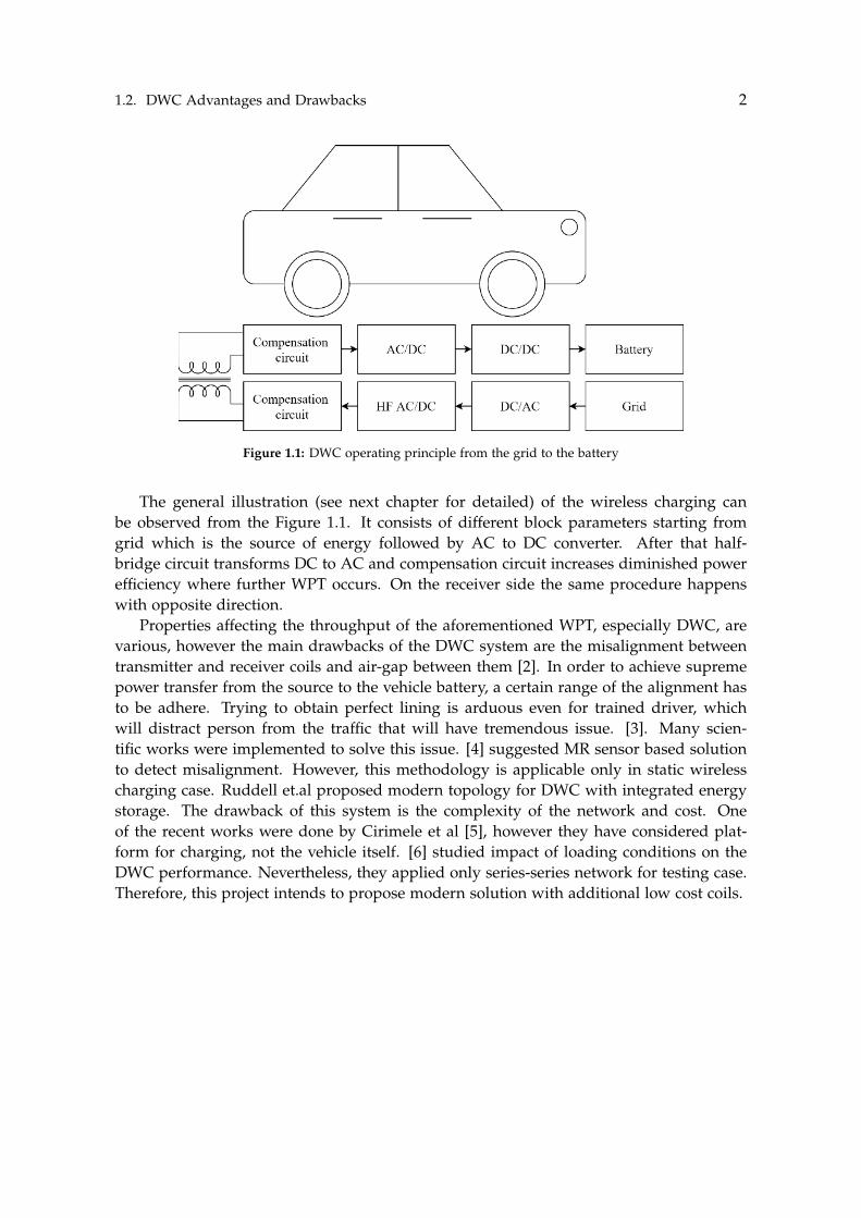
Figure 1.1: DWC operating principle from the grid to the battery
The general illustration (see next chapter for detailed) of the wireless charging canbe observed from the Figure 1.1. It consists of different block parameters starting fromgrid which is the source of energy followed by AC to DC converter. After that half-bridge circuit transforms DC to AC and compensation circuit increases diminished powerefficiency where further WPT occurs. On the receiver side the same procedure happenswith opposite direction.
Properties affecting the throughput of the aforementioned WPT, especially DWC, arevarious, however the main drawbacks of the DWC system are the misalignment betweentransmitter and receiver coils and air-gap between them [2]. In order to achieve supremepower transfer from the source to the vehicle battery, a certain range of the alignment hasto be adhere. Trying to obtain perfect lining is arduous even for trained driver, whichwill distract person from the traffic that will have tremendous issue. [3]. Many scien-tific works were implemented to solve this issue. [4] suggested MR sensor based solutionto detect misalignment. However, this methodology is applicable only in static wirelesscharging case. Ruddell et.al proposed modern topology for DWC with integrated energystorage. The drawback of this system is the complexity of the network and cost. Oneof the recent works were done by Cirimele et al [5], however they have considered plat-form for charging, not the vehicle itself. [6] studied impact of loading conditions on theDWC performance. Nevertheless, they applied only series-series network for testing case.Therefore, this project intends to propose modern solution with additional low cost coils.

Chapter 2
Theory and Analysis
2.1 Optimal WPT Topology
Power between transmitter and receiver side can be altered and improved according to thedifferent WPT circuit combinations. Regarding to the [7], there are mainly four types ofthe WPT topologies: inductive, capacitive, magnetic gear and resonant inductive. Each ofthe methods has own benefits and operating principles which is summarised in the table2.1. As it can be observed, some topologies have medium efficiency, at the same lowerprice. According to the designer decision and application purpose these topologies will beopted for.
Another factor affecting the performance of the DWC of EV is the hardware of thesystem. Generally, it contains rectifiers, inverters, drivers and etc (detailed explanation ofthe hardware will be covered in the next chapter). One of such elements in the networkis the compensation circuit. It is used in order to increase the efficiency of the poweron the secondary side. Usually, two compensation circuits are applied for single pair ofenergy transformation, where one is located on the transmitter side and other one in thereceiver coil side. The most recent research on compensation was conducted by Huanget. al. They in depth had considered the relationship between compensation network and
WPT topol-ogy
Efficiency Frequencyrange(kHz)
Power level Price Size
Inductive High 10-50 Medium\High Medium\High MediumCapacitive Medium 100-600 Low Low LowPermanentmagnet
Low 0.05-0.5 Medium High High
Resonantinductive
Medium 10-150 Medium\Low Medium High
Table 2.1: Characteristics of different WPT topology
3
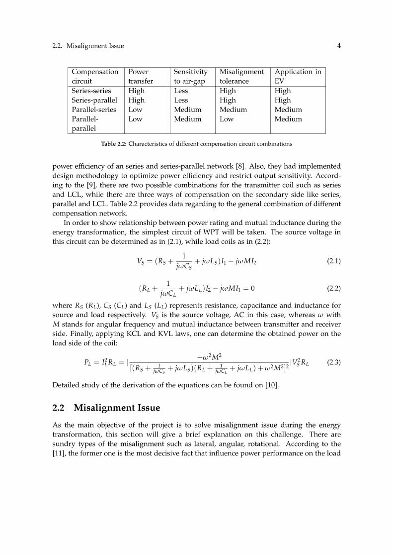
2.2. Misalignment Issue 4
Compensationcircuit
Powertransfer
Sensitivityto air-gap
Misalignmenttolerance
Application inEV
Series-series High Less High HighSeries-parallel High Less High HighParallel-series Low Medium Medium MediumParallel-parallel
Low Medium Low Medium
Table 2.2: Characteristics of different compensation circuit combinations
power efficiency of an series and series-parallel network [8]. Also, they had implementeddesign methodology to optimize power efficiency and restrict output sensitivity. Accord-ing to the [9], there are two possible combinations for the transmitter coil such as seriesand LCL, while there are three ways of compensation on the secondary side like series,parallel and LCL. Table 2.2 provides data regarding to the general combination of differentcompensation network.
In order to show relationship between power rating and mutual inductance during theenergy transformation, the simplest circuit of WPT will be taken. The source voltage inthis circuit can be determined as in (2.1), while load coils as in (2.2):
VS = (RS +1
jωCS+ jωLS)I1 − jωMI2 (2.1)
(RL +1
jωCL+ jωLL)I2 − jωMI1 = 0 (2.2)
where RS (RL), CS (CL) and LS (LL) represents resistance, capacitance and inductance forsource and load respectively. VS is the source voltage, AC in this case, whereas ω withM stands for angular frequency and mutual inductance between transmitter and receiverside. Finally, applying KCL and KVL laws, one can determine the obtained power on theload side of the coil:
PL = I2LRL = | −ω2M2
[(RS +1
jωCS+ jωLS)(RL +
1jωCL
+ jωLL) + ω2M2]2|V2
S RL (2.3)
Detailed study of the derivation of the equations can be found on [10].
2.2 Misalignment Issue
As the main objective of the project is to solve misalignment issue during the energytransformation, this section will give a brief explanation on this challenge. There aresundry types of the misalignment such as lateral, angular, rotational. According to the[11], the former one is the most decisive fact that influence power performance on the load

2.2. Misalignment Issue 5
Pa
Pb
T
R
r
a
dlT
x
x
y
y
z
Figure 2.1: Lateral misalignment between transmitter and receiver coils
side. Therefore, this project will consider the lateral misalignment only, Figure 2.1, whilethorough analysis on the remaining is applicable on [3].
Applying the Ampere’s law [12] for closed path:∮B dl = µ0NI (2.4)
where B is the magnetic flux, µ0 is the permeability constant, N is the number of turnsand I is the current. Also, from the Figure 2.1 the magnetic field intensity derived as:
H =IT
4π
n
∑i=1
a2i
2√(a2
i + ∆2)3(2.5)
where IT is the transmitter side current and other parameters shown in the Figure 2.1.Moreover, the magnetic flux density (B) in terms of the voltage can be computed by ap-plying the Faraday’s law [13]:
Vi = −ddt
∮B ds (2.6)
and signifying B with field strength:
B = µH = µ0µr H (2.7)

2.2. Misalignment Issue 6
Figure 2.2: Variation of mutual inductance value regarding to the misalignment over y-axis and x-axis
with combining the equations (2.10), (2.12) and putting into (2.11), one can achieve pick-upvoltage formulation:
Vi = jµ0ωHk
∑j=1
πb2j (2.8)
while bj is the radial length of the receiver coil. Equation (2.13) states that induced voltageon the load coil side is directly proportional to the arising magnetic field strength. WhileH itself indirectly related to the ∆ (1.10) which is the lateral misalignment between charg-ing and pick-up coils. Therefore, mathematical computation exhibits that higher lateralmisalignment leads to decreased induced voltage, which also cause reduction in power onthe receiver coil (2.6). In order to visualize this pattern, refer to the (2.8) where mutual in-ductance value is positively correlated with load power. Thus, inductance between sourceand load will be diminished if the power does so which is dependent on the misalignmentvalue. Figure 2.2 illustrates aforementioned conclusion. It shows position of transmitterand receiver with respect to each other over x-axis and y-axis. It can be clearly observedthat during the perfect alignment, M has the maximum available value, whereas it atten-uates across broad area of the misalignment reaching the lowest point on the 150mm onboth axis.

Chapter 3
Proposed methodology
3.1 Coil Models
Due to the dynamic mutual inductance existence in DWC, the voltage level of the receiveris not helpful for identifying the misalignment [14]. Two sensor coils were proposed inthe Capstone I, which will have different voltage levels at misalignments due to non-equaldistances [15]. Figure 3.1 depicts the configuration of the model of proposed methodologyand is viewed for the simulation in the Ansys Maxwell software. The larger bottom and topcoils are transmitter and receiver coils respectively, whereas two small coils are sensor coils.For the scope of the DWC, two coils are enough as neither front nor rear misalignmentneeds to be discriminated.
Figure 3.1: Simulation Model
7
3.2. System Model 8
3.2 System Model
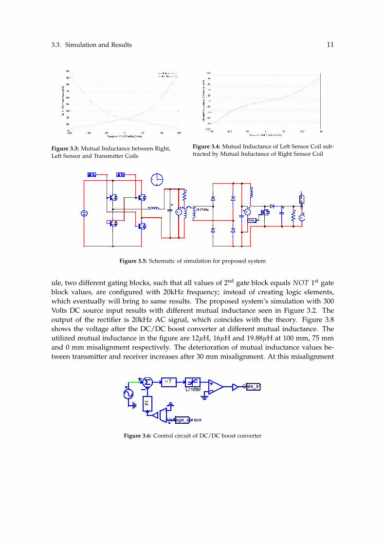
In order to test usability and effectiveness of the coil model, the real-life case hardware isneeded, however, only software simulation of circuit was constructed as shown in Figure3.5. In this circuit (1) DC power is converted to AC power, (2) AC power is passed due tomutual inductance from primary (transmitter) to secondary (receiver side), (3) AC poweris converted back to DC power fed into the battery. The elements, their significance andresponsibilities in the system are as follows:
• Microcontroller. The microcontroller generates the pulses, which are used as driversinput. Also, the microcontroller is capable to read the voltage level of sensor, andidentify the direction of turn to align the receiver with transmitter.
• Driver. The IGBT based inverters and Power Mosfets used for the inverter andDC/DC boost converter need the driver to control their gates, as specific voltagelevel is required, which is not maintained by the microcontroller in real-life hard-ware setup scenario, however, this is out of the scope of the simulation.
• Inverter. For obtaining high-frequency AC signal (for power transfer 20kHz is treatedas high frequency), the inverter controlled by driver is vital. For the hardware imple-mentation IGBT based H-bridge converter is suggested and is used in the simulation.Two drivers are required to input complementary signal, e.g. when one driver is atstate Vcc, the other is at state 0.
• Compensation network. The power transfer efficiency through inductive coupling ishighly contingent upon the reactance level at utilized frequency, whereas the com-pensation network gives opportunity to transfer power at uttermost efficiency, ifvalues are correctly computed and constructed. The LCL-N topology showed rel-atively high performance at its low cost due to utilization of only single inductiveload in series (3.1) and capacitive load in parallel (3.2) connected to the transmittingcoil. In theory, this topology is most desired to the scope of our project as instead ofconnecting the compensation network to 4 coils (transmitter, receiver, 2 sensor coils),single compensation will be enough to achieve good performance of power transferto receiver and coil sensors. The efficient power transfer to sensor coils is also desiredas voltage levels should be high enough to be differentiated.
Lseries = Ltx (3.1)
Cparallel =1
w20Ltx
(3.2)
• Rectifier. Only DC power is fed into the battery, thus received AC at the secondaryside is converted to DC by the rectifier. For rectifier the full-wave rectifier withcapacitor for smoothing is proposed. However, the output of the rectifier will vary

3.3. Simulation and Results 9
due to the nature of DWC, where mutual inductance is dynamic and voltage levelsvary.
• Closed loop DC/DC Boost converter. The battery should be always charged at volt-age rate of 1-2 V higher than the battery’s rated voltage for increasing the number ofbattery cycles. For the purpose of stabilizing the voltage, closed loop DC-DC boostconverter with capacitor is proposed, which can result in stable voltage, hence elon-gation of battery life. The closed loop is controlled by changing the duty cycle andthe frequency of gate, which is microcontroller’s burden, and the voltage gain is asfollows:
Vout =Vin
1− D, (3.3)
whereD =
ton
ton + to f f(3.4)
The DC/DC boost converter is not the only option to resist the voltage pulsations, whichare detrimental for the battery. The use of ultracapacitors connected in parallel to thebattery is feasible, or supercapacitors even are able to replace the batteries, but this issubject to experiments during the real-life hardware setup. Otherwise, the separate batterymanagement system (BMS) of the battery could be also utilized for obtaining high-qualitycontrol during the charging of the battery at appropriate voltage and current. It shouldbe noted that the possible expenses for the proposed implementation of hardware setupwere tried to be minimized and the hardness of the construction lightened to be feasiblefor contruction.
3.3 Simulation and Results
From quantitative analysis, the correlation of power or voltage and mutual inductance isdirect proportionality. The simulation, thus, considers mutual inductance for the verifica-tion of the theory. The coil parameters were chosen as in [16] for the main coils and thedimensions of the peripheral sensor coils are arbitrary, however, more turns and largerdiameter of conductors will induce larger voltage which is undesired for the sensor coilswhich results in power loss of the receiver.
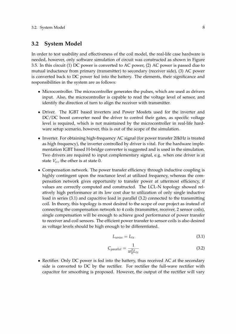
Two simulations with and without the sensor coils were done to prove the negligentdisturbance of the sensor coils on the WPT (see Figure 3.2). Another desired feature ofthe sensor coils is precision. The simulation’s purpose is to show that voltage inducedinside the sensor coils due to transmitter are different. Figure 3.3 shows that the mutualinductance between sensor coils and transmitter, with increase of mutual inductance forleft sensor coil while shift is to the right direction and vice-versa for right sensor coil. Atno misalignment, however, the intersection does not occur due to unsymmetrical natureof the coils during the simulation. If this is the case for the hardware, then calibration

3.3. Simulation and Results 10
Table 3.1: Coil Parameters
Parameter Transmitter and Sensor CoilsReceiver Coils
Number of Turns 18 3Inner Diameter 140 mm 30 mm
Conductor Diameter 4 mm 2 mmTurn spacing 1 mm 1 mm
Outer Diameter 320 mm 24 mm
Figure 3.2: Mutual Inductance between Receiver and Transmitter with and without Sensor Coils
or offset could be taken for consideration while identifying the direction of misalignment.Figure 3.4 shows how the direction to align perfectly is identified, e.g. by consideringnegative mutual inductance, hence negative voltage result shows the direction to align asright, and vice-versa for positive voltage.
The simulation of the system was implemented in PSIM software, which is suitable forthe simulation of power electronics circuits. The purpose of the simulation is to ensure theproper operation of the whole system. For simulation to be sound with sensor coils model,the results of in Section 3.3 were used for self and mutual inductance, both for testing withthe receiver and sensor coils. The parameters were chosen as discussed in previous sectionfor LCL-N compensation network, whereas the capacitance values for rectifier and DC-DCboost converter were approximated. Overall, the simulation improvements as well as theselection of more precise values for components is desirable. The circuit used for thesimulation can be seen from Fig.3.5, the simulation scenario is different from the real-lifescenario, so that during simulation the control circuit used for the closed loop DC/DCboost converter is made using PID (refer to figure 3.6).
Since PSIM requires only gate blocks to be wired to the gate junction of the IGBT mod-
3.3. Simulation and Results 11
Figure 3.3: Mutual Inductance between Right,Left Sensor and Transmitter Coils
Figure 3.4: Mutual Inductance of Left Sensor Coil sub-tracted by Mutual Inductance of Right Sensor Coil
Title Designed by
Revision Page 1 of 1
10.8749u
Gate_in
Figure 3.5: Schematic of simulation for proposed system
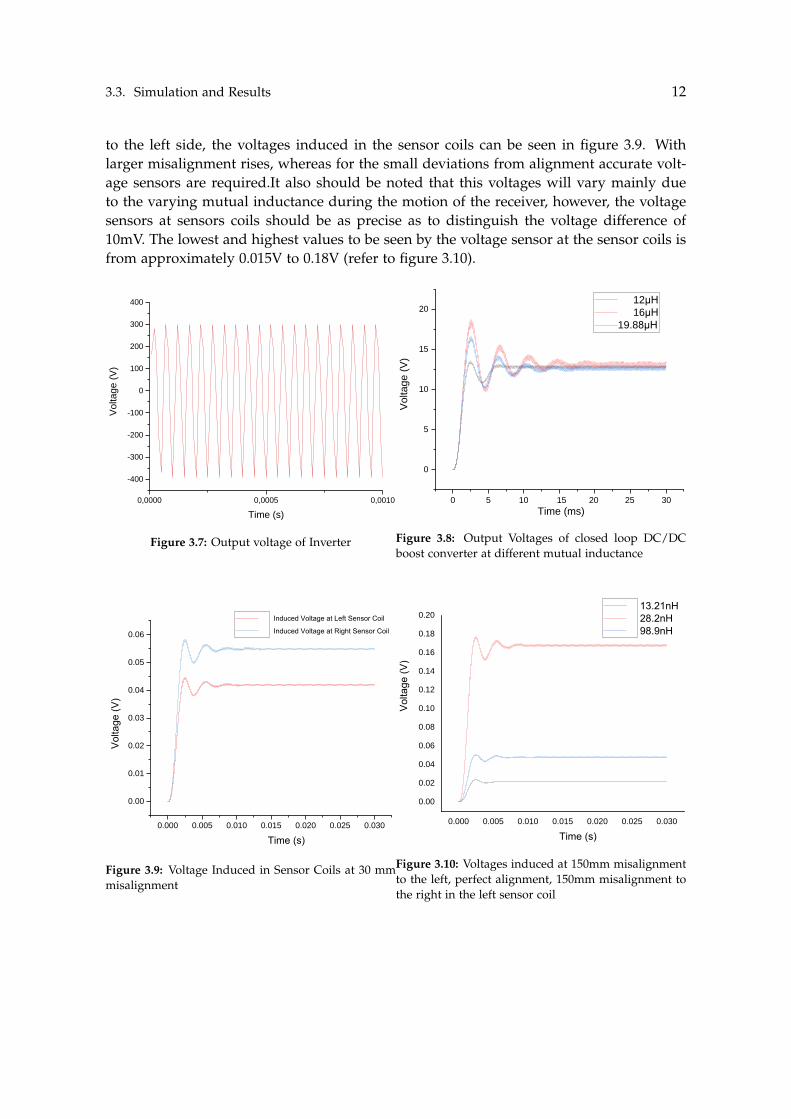
ule, two different gating blocks, such that all values of 2nd gate block equals NOT 1st gateblock values, are configured with 20kHz frequency; instead of creating logic elements,which eventually will bring to same results. The proposed system’s simulation with 300Volts DC source input results with different mutual inductance seen in Figure 3.2. Theoutput of the rectifier is 20kHz AC signal, which coincides with the theory. Figure 3.8shows the voltage after the DC/DC boost converter at different mutual inductance. Theutilized mutual inductance in the figure are 12µH, 16µH and 19.88µH at 100 mm, 75 mmand 0 mm misalignment respectively. The deterioration of mutual inductance values be-tween transmitter and receiver increases after 30 mm misalignment. At this misalignment
Title Designed by
Revision Page 2 of 3
19.8749u
Gate_in
Voltage_sensor
Limiter
sT
Figure 3.6: Control circuit of DC/DC boost converter
3.3. Simulation and Results 12
to the left side, the voltages induced in the sensor coils can be seen in figure 3.9. Withlarger misalignment rises, whereas for the small deviations from alignment accurate volt-age sensors are required.It also should be noted that this voltages will vary mainly dueto the varying mutual inductance during the motion of the receiver, however, the voltagesensors at sensors coils should be as precise as to distinguish the voltage difference of10mV. The lowest and highest values to be seen by the voltage sensor at the sensor coils isfrom approximately 0.015V to 0.18V (refer to figure 3.10).
0,0000 0,0005 0,0010
-400
-300
-200
-100
0
100
200
300
400
Voltage (
V)
Time (s)1
Figure 3.7: Output voltage of Inverter
0 5 10 20 25 30
0
5
10
15
20
Voltage (
V)
15
Time (ms)
12µH16µH
19.88µH
1
Figure 3.8: Output Voltages of closed loop DC/DCboost converter at different mutual inductance
0.000 0.005 0.010 0.015 0.020 0.025 0.030
0.00
0.01
0.02
0.03
0.04
0.05
0.06
Volta
ge (V
)
Time (s)1
Induced Voltage at Left Sensor Coil
Induced Voltage at Right Sensor Coil
Figure 3.9: Voltage Induced in Sensor Coils at 30 mmmisalignment
0.000 0.005 0.010 0.015 0.020 0.025 0.030
0.00
0.02
0.04
0.06
0.08
0.10
0.12
0.14
0.16
0.18
0.20
Volta
ge (V
)
Time (s)
13.21nH 28.2nH 98.9nH
1
Figure 3.10: Voltages induced at 150mm misalignmentto the left, perfect alignment, 150mm misalignment tothe right in the left sensor coil
Chapter 4
Conclusion
Optimal methodology for lateral misalignment detection with sensor coils was proposedduring the Capstone I and simulation was conducted according to the previous studies de-sign parameters. The obtained results prove the analytical analysis and ability of the newmethod to eliminate misalignment challenge to some extent. In addition, the performanceof the topology can be enhanced by applying suitable WPT circuits, which was mentionedbefore. Also, the shape of the receiver and transmitter during this project is taken as cir-cular, while there is a possibility to integrate other coil forms such as rectangular and soon.
The primary aim for the Capstone II is to construct practical coils and conduct a testfor the efficiency. In order to do that various equipment including software application arerequired.[17]
13
Bibliography
[1] X. Mou et al. “Survey on magnetic resonant coupling wireless power transfer tech-nology for electric vehicle charging”. In: IET Power Electronics 12.12 (2019), pp. 3005–3020.
[2] K.A. Kalwar et al. Coil Design for High Misalignment Tolerant Inductive Power TransferSystem for EV Charging. 2016.
[3] A. Ahmad and M.S. Alam. “A Comprehensive Review of Wireless Charging Tech-nologies for Electric Vehicles”. In: IEEE Transaction on Transportation Electrification.2018.
[4] T. V. Jeshma and B. George. “MR Sensor-Based Coil Alignment Sensing System forWirelessly Charged EVs”. In: IEEE Sensors Journal 20.10 (2020), pp. 5588–5596.
[5] V. Cirimele et al. “The Fabric ICT Platform for Managing Wireless Dynamic ChargingRoad Lanes”. In: IEEE Transactions on Vehicular Technology 69.3 (2020), pp. 2501–2512.
[6] H. H. Kabalan et al. “The Impact of Coupling and Loading Conditions on the Per-formance of S-S EV Dynamic Wireless Charging Systems”. In: 2019 International Con-ference on Electrical and Computing Technologies and Applications (ICECTA). 2019, pp. 1–5.
[7] Chirag Panchal and Sascha Stegen. “Review of static and dynamic wireless elec-tric vehicle charging system”. In: Engineering Science and Technology, an InternationalJournal 21 (June 2018). doi: 10.1016/j.jestch.2018.06.015.
[8] Z. Huang et al. “Design of Series/Series-Parallel Compensated Inductive PowerTransfer Converter as Wireless Grid to Vehicle Interface”. In: 2019 IEEE Vehicle Powerand Propulsion Conference (VPPC). 2019, pp. 1–5.
[9] Y. Zhang et al. “A High-Power Wireless Charging System Using LCL-N Topology toAchieve a Compact and Low-Cost Receiver”. In: IEEE Transactions on Power Electron-ics 35.1 (2020), pp. 131–137.
[10] Alireza Dayerizadeh. Dynamic Wireless Charging for Electric Vehicles: Approaches forReflexive Field Containment Using Reactive Components. Jan. 2020. doi: 10.13140/RG.2.2.11643.67369.
14

Bibliography 15
[11] Y. Gao et al. “Misalignment effect on efficiency of wireless power transfer for electricvehicles”. In: 2016 IEEE Applied Power Electronics Conference and Exposition (APEC).2016, pp. 3526–3528.
[12] E. R. Williams and P. T. Olsen. “A Method to Measure Magnetic Fields AccuratelyUsing Ampere’s Law”. In: IEEE Transactions on Instrumentation and Measurement 27.4(1978), pp. 467–469.
[13] A. E. Umenei, Y. Melikhov, and D. C. Jiles. “Analytic Solution for Variations ofMagnetic Fields in Closed Circuits: Examination of Deviations From the “Standard”Ampere’s Law Equation”. In: IEEE Transactions on Magnetics 47.4 (2011), pp. 734–737.
[14] D. Kishan and P. S. R. Nayak. “Wireless power transfer technologies for electric ve-hicle battery charging — A state of the art”. In: 2016 International Conference on SignalProcessing, Communication, Power and Embedded System (SCOPES). 2016, pp. 2069–2073. doi: 10.1109/SCOPES.2016.7955812.
[15] Raymond A. Serway and Chris Vuille. Essentials of college physics. Thomson-Brooks/Cole,2007.
[16] Ainur Rakhymbay et al. “Precise Analysis on Mutual Inductance Variation in Dy-namic Wireless Charging of Electric Vehicle”. In: Energies 11 (Mar. 2018), p. 624. doi:10.3390/en11030624.
[17] Ivan Cortes. “Automatic Positioning System for Inductive Wireless Charging Devicesand Application to Mobile Robot”. MA thesis. Texas A M University, 2007.