dynamic simulation of hybrid-driven planar five-bar …cdn.intechweb.org/pdfs/19920.pdfdynamic...
TRANSCRIPT

Dynamic Simulation of Hybrid-driven Planar Five-bar Parallel Mechanism Based on SimMechanics and Tracking Control Regular Paper
Bin Zi*, Jianbin Cao and Zhencai Zhu School of Mechanical and Electrical Engineering, China University of Mining and Technology, China *Corresponding author E-mail: [email protected] Received 14 June 2011; Accepted 19 Aug 2011
Abstract This paper investigates dynamic simulation and trajectory tracking control of hybrid‐driven planar five‐bar parallel mechanism (HPPM). To begin with, a simulation model of dynamics based on MATLAB/SimMechanics is established. Then, traditional PD control and closed loop PD‐type iterative learning control of the HPPM are designed. At the end, the simulation based on SimMechanics is carried out, which acquires angular, angular velocity, angular acceleration of two driving links and constraint reaction of kinematic pairs at any time. In addition, the performance of the closed loop PD‐type iterative learning control is compared with that of the traditional PD controller through simulations of the HPPM in the presence of the model external disturbances. The simulation results indicate that a perfect trajectory tracking of end‐effector of the HPPM is achieved by the closed loop PD‐type iterative learning controller. Keywords Hybrid‐driven planar five‐bar parallel mechanism; SimMechanics; Dynamic simulation; Iterative learning control
1. Introduction Recently, as the rapid development of parallel robotics and controllable mechanism, hybrid‐driven planar
five‐bar parallel mechanism (HPPM) which is a simple two degree of freedom (DOF) mechanism, has been widely used in mechanical design[1‐2]. The HPPM is a kind of machine whose drive system is composed of two types of actuators: constant velocity (CV) motor and servomotor. The CV motor provides main power and motion required, while the servomotor acts as a motion regulation and control device. The two types of motion inputs are synthesized through a 2‐DOF mechanism and output high performance movement [3]. The HPPM has the advantages of high efficiency, high payload and application flexibility, because the CV motor could undertake a high constant workload while the servomotor can be real‐time regulated to meet the change of task or operation. Kinematic analysis and dynamic analysis of the HPPM are the basis for mechanism design, motion evaluation and control. SimMechanics does not need to create dynamic mathematical model and write program, and has the features of modeling with a simple method, powerful simulation function and so on [4]. So, it is an efficient tool for dynamic simulation of mechanism. When the CV motor carries the time‐varying workload, it will produce the velocity fluctuation. Such fluctuation propagates to the end‐effector of the HPPM. As a result, the end‐effector of the HPPM can not accurately move along the desired trajectory. Clearly, closed loop control
Int J Adv Robotic Sy, 2011, Vol. 8, No. 4, 28-3328 www.intechweb.orgwww.intechopen.com
Int J Adv Robotic Sy, 2011, Vol. 8, No. 4, 28-33

of the HPPM is key important. Many scholars have been studied it in depth. In [5], a reduced dynamic model of a five‐bar linkage mechanism is proposed, and a PD plus full gravity compensation control strategies is designed. In [6], a computed‐torque control method for trajectory tracking of the HPPM is investigated. In [7] and [8], a sliding model control strategy was employed to drive the HPPM to follow a predesigned trajectory. Iterative learning control (ILC) method originated in the study of industrial robot manipulators, which repeats the same task from trial to trial. ILC is a technique for improve trajectory tracking performance of the system that executes a same operation repeatedly. Through decades of development, ILC has been widely applied in the control field, which robot and other difficult to establish accurately model[9]. The natural of repetitive motion and nonlinear feature of the HPPM makes it possible to apply ILC to improve the tracking performance from iteration to iteration. In this investigation it will be focused on dynamic simulation of the HPPM based on MATLAB/ SimMechanics and Traditional PD control and closed loop PD‐type iterative learning control for trajectory tracking of end‐effector of the HPPM. 2. System description and Modeling The design of the 2‐DOF HPPM follows a built‐up modular system as illustrated in Fig.1. The HPPM is composed of five‐bar linkage mechanism. A simple schematic of the HPPM representing the coordinate systems is shown in Fig. 2. Link AB which is driven by CV motor and link DE which is driven by servomotor are two driving links. Link BC and link CD are driven by the two driving links, so that the end‐effector can output the flexible trajectory. This paper assumes that the length of links are l1, l2, l3, l4, l5, the angel between links and
X‐axis are 1 2 3 4, , , ,0q q q q , the mass of links are m1,m2,m3,
m4,the rotational inertia of links are I1, I2, I3, I4.
Figure 1. Model of the HPPM
Figure 2. Schematic diagram of the HPPM MATLAB/SimMechanics extends Simulink with the tools for modeling and simulating mechanical systems. SimMechanics is one of the physical modeling methods, which modeling and design for systems according to basic physical principals. A SimMechanics model includes a set of blocks (body, joint, constraint, coordinate, sensor and so on), which indicate physical components. In the module environment, SimMechanics uses rigid body and kinematic pair to describe the movement relationship between every rigid body. Dynamic SimMechanics model of the HPPM is shown in Fig.3.
Figure 3. Dynamic simulation model of HPPM in SimMechanics
A
B
C
D
E1q
2q3q
4q
1l
2l 3l
4l
5lx
y
End –effector
ddct 4ddct 4
To Workspace1simout 1
To Workspacesimout
Scope 2
Scope 1
Revolute E
BF
Revolute D
BF
Revolute C
B F
Revolute B
BF
Revolute A
BF
MachineEnvironment Env
Link DE
CS
1C
S2
Link CD
CS1 CS2
Link BC
CS
1C
S2
Link AB
CS
1C
S2
Joint Sensor 2
Joint Sensor 1
Joint Actuator 1
Joint Actuator
Integrator 31s
Integrator 21s
Integrator 1
1s
Ground 2
Ground 1
Constant 2
0 Constant
0.7068
Int J Adv Robotic Sy, 2011, Vol. 8, No. 4, 28-3329 www.intechweb.orgwww.intechopen.com
Initial position of links can be obtained by kinematic analysis of the HPPM. According to geometric relations of mechanism, as depicted in Fig.2, it can be derived the coordinates of point C:
1 1 2 2 5 4 4 3 3cos cos cos coscx l l l l lq q q q= + = + + (1)
1 1 2 2 3 3 4 4sin sin sin sincy l l l lq q q q= + = + (2)
From Eqs. (1) and (2), it can be found that 1q and 4q are independent in the system, and 2q and 3q can be determined by 1q and 4q as follows:
2 2 2
3 2arctan A A B CB C
qé ù + -ê ú= ê ú-ê úë û
(3)
where
3 4 4 1 3 12 sin 2 sinA l l l lq q= -
3 5 1 3 1 3 4 42 2 cos 2 cosB l l l l l lq q= - +
2 2 2 2 21 2 3 4 5 1 4 1 42 sin sinC l l l l l l l q q= - + + + -
1 5 1 4 5 4 1 4 1 42 cos 2 cos 2 cos cosl l l l l lq q q q- + -
From Eqs. (2) and (3) above, we get
3 3 4 4 1 12
2
sin sin sinarcsin l l ll
q q qq
é ù+ -ê ú= ê úë û (4)
Dynamic simulation model parameters include control parameters of kinematic pair and physical parameters of rigid body, which could be set by variables input. The initial variable parameters of rigid body and that of kinematic pair can be written in MATLAB m‐file and imported in the workspace of MATLAB before dynamic simulation of the HPPM. If the structure parameters of the HPPM need to be changed, only need to change in the M file, there is no need to set parameters for every module in the model. 3. Trajectory tracking control Based on the results in the [7] and consider the various errors and disturbances, dynamic equation of the HPPM can be described as follows:
( ) ( , ) ( ) dM C Gq q q q q q t t¢ ¢ ¢ ¢+ + = - (5)
where
T1 4[ ]q q q= ; T
1 2 3 4[ ]q q q q q¢ = T
1 4[ ] q q q= ; T1 2 3 4[ ] q q q q q¢ =
( )M q¢ is the symmetric positive definite inertia matrix;
( , )C q q¢ ¢ is the centrifugal force and Coriolis force
matrix; ( )G q¢ is the gravity matrix; T1 4[ , ]t t t= is
the control torque, 1t is the torque input by the CV
motor, 4t is the torque input by the servomotor; dt is
the error and disturbance. The elements in the matrix can
be found in [7]. 3.1 Traditional PD feedback control The traditional PD control is widely used in control systems because of its simple algorithm and easy implementation. The PD control law for the HPPM is described by the following formulation:
d PK e K et = + (6)
In the equation, the angular tracking error and angular
velocity tracking error are defined as:
de q q= - ; de q q= - (7)
Where dq is the desired angular position vector T
1 4[ ]d dq q ; dq is the desired angular velocity vector
T1 4[ ]d d q q ; dK is the derivative gain; PK is the
proportional gain.
The block diagram of traditional PD control for the
HPPM is shown in Fig.4. Figure 4. Control diagram of traditional PD for the HPPM 3.2 Iterative learning control
( )dy t is desired trajectory of the HPPM; ( )ky t is output trajectory of the kth iterative operation;
( ) ( ) ( )k d ke t y t y t= - is the trajectory tracking error.
Iterative learning control objective for the HPPM is to
make output trajectory track desired trajectory as closely
as possible.
Consider the (k+1)th iterative operation for the system (5),
the closed loop PD‐type iterative learning control law is
dqPD
Control lawHPPM system+
-q
Bin Zi, Jianbin Cao and Zhencai Zhu: Dynamic Simulation of Hybrid-driven Planar Five-bar Parallel Mechanism Based on SimMechanics and Tracking Control
30www.intechweb.orgwww.intechopen.com
given by
1 1( ) ( ) ( ( ) ( ))k k P d ku t u t K t tq q+ += + - +
1( ( ) ( ))d d kK t tq q +- (8)
Where 1( ) ( )d kt tq q +- and 1( ) ( )d kt t q q +- represent
the angular error and angular velocity error of the (k+1)th
iterative operation. The block diagram of iterative learning control of the HPPM is given in Fig.5.
Figure 5. Block diagram of ILC for the HPPM 4. Simulation study and analysis The end‐effector of the HPPM is required to move from point M (0.3, 0.3), to point N (0.5, 0.5). The running time is 2 s. Physical parameters of the HPPM and control parameters are listed as follows:
l1=0.21m, l2=0.53m, l3=0.47m, l4=0.25m, l5=0.53m,
m1=0.33kg,m2=0.832kg,m3=0.738kg,m4=0.393kg,I1=0.0048
Kgm2,I2=0.0195 Kgm2,I3=0.0136 Kgm2,I4=0.0082 Kgm2,
Kp=diag(200 , 200) , Kd=diag(100 , 100) ,
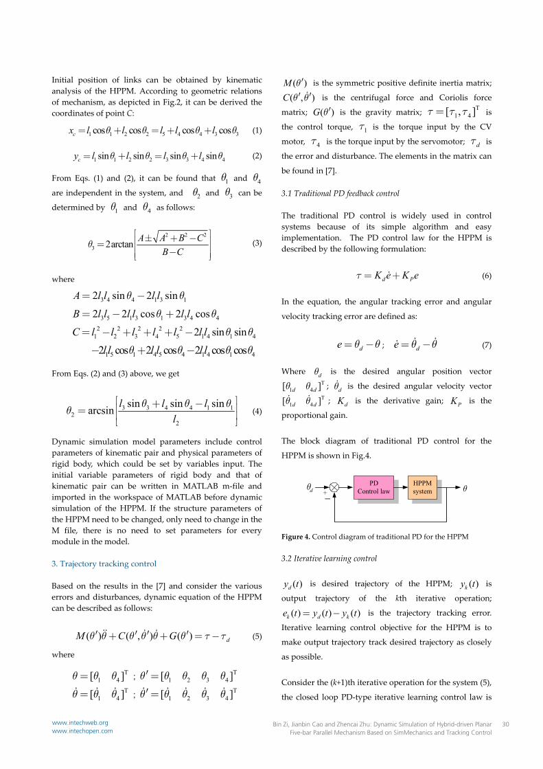
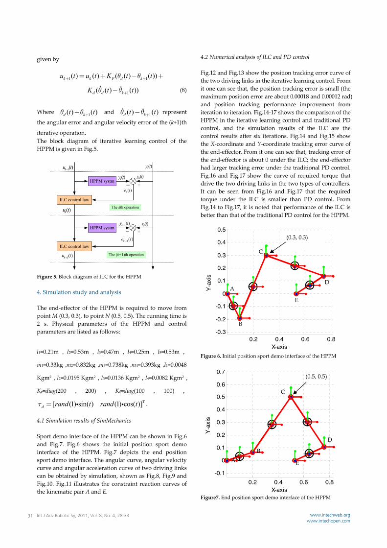
T[ (1) sin( ) (1) cos( )]d rand t rand t t = . 4.1 Simulation results of SimMechanics Sport demo interface of the HPPM can be shown in Fig.6 and Fig.7. Fig.6 shows the initial position sport demo interface of the HPPM. Fig.7 depicts the end position sport demo interface. The angular curve, angular velocity curve and angular acceleration curve of two driving links can be obtained by simulation, shown as Fig.8, Fig.9 and Fig.10. Fig.11 illustrates the constraint reaction curves of the kinematic pair A and E.
4.2 Numerical analysis of ILC and PD control Fig.12 and Fig.13 show the position tracking error curve of the two driving links in the iterative learning control. From it one can see that, the position tracking error is small (the maximum position error are about 0.00018 and 0.00012 rad) and position tracking performance improvement from iteration to iteration. Fig.14‐17 shows the comparison of the HPPM in the iterative learning control and traditional PD control, and the simulation results of the ILC are the control results after six iterations. Fig.14 and Fig.15 show the X‐coordinate and Y‐coordinate tracking error curve of the end‐effector. From it one can see that, tracking error of the end‐effector is about 0 under the ILC; the end‐effector had larger tracking error under the traditional PD control. Fig.16 and Fig.17 show the curve of required torque that drive the two driving links in the two types of controllers. It can be seen from Fig.16 and Fig.17 that the required torque under the ILC is smaller than PD control. From Fig.14 to Fig.17, it is noted that performance of the ILC is better than that of the traditional PD control for the HPPM.
Figure 6. Initial position sport demo interface of the HPPM
Figure7. End position sport demo interface of the HPPM
0.2 0.4 0.6 0.8-0.3
-0.2
-0.1
0
0.1
0.2
0.3
0.4
0.5
X-axis
Y-axis
A
B
C
D
E
(0.3, 0.3)
0.2 0.4 0.6 0.8-0.1
0
0.1
0.2
0.3
0.4
0.5
0.6
0.7
X-axis
Y-axis
D
AB
E
C
(0.5, 0.5)
HPPM systm
ILC control law
HPPM systm
ILC control law
1( )ku t-( )dy t
( )ky t
( )ke t+-
( )ku t
1( )ky t+
+-( )dy t
( )dy t
1( )ke t+
The kth operation
The (k+1)th operation1( )ku t+
Int J Adv Robotic Sy, 2011, Vol. 8, No. 4, 28-3331 www.intechweb.orgwww.intechopen.com

Figure 8. The angular curve of link AB and link DE Figure 9. The angular velocity curve of link AB and link DE Figure 10. The angular acceleration curve of link AB and link DE
Figure 11. Constraint reaction curve of the kinematic pairs
Figure 12. Position tracking error curve of the link AB
Figure 13. Position tracking error curve of the link DE Figure 14. X‐coordinate tracking error curve of the end‐effector
Figure 15. Y‐coordinate tracking error curve of the end‐effector
0.0 0.5 1.0 1.5 2.0-1.2
-1.0
-0.8
-0.6
-0.4
-0.2
0.0
0.2
0.4
0.6
Link DE
Link AB
/t s
0.0 0.5 1.0 1.5 2.0-0.5
0.0
0.5
1.0
1.5
Link DE
Link AB
/t s
0.0 0.5 1.0 1.5 2.055
60
65
70
75
80
85
90
E
A
/t s
Force/
/t s
0.0 0.5 1.0 1.5 2.0-1.0-0.8-0.6-0.4-0.20.0
0.20.40.60.8
1.0
Link DE
Link AB
/t s
Position error/rad
0.0 0.5 1.0 1.5 2.0
-2.0x10⁻⁴
-1.5x10⁻⁴
-1.0x10⁻⁴
-5.0x10⁻⁵
0.0
5.0x10⁻⁵
1.0x10⁻⁴
1.5x10⁻⁴
6th Iteration
4th Iteration
2th Iteration
/t s
Position error/rad
0.0 0.5 1.0 1.5 2.0-6.0x10⁻⁵
-4.0x10⁻⁵
-2.0x10⁻⁵
0.02.0x10-5
4.0x10⁻⁵
6.0x10⁻⁵
8.0x10⁻⁵
1.0x10⁻⁴
1.2x10⁻⁴
1.4x10⁻⁴
6th Iteration
4th Iteration
2th Iteration
Error/
/t s0.0 0.5 1.0 1.5 2.0
-0.0002
0.0000
0.0002
0.0004
0.0006
0.0008
0.0010
0.0012
0.0014
0.0016
0.0018
ILC
PD Control
0.0 0.2 0.4 0.6 0.8 1.0 1.2 1.4 1.6 1.8 2.0
0.0000
0.0005
0.0010
0.0015
0.0020
0.0025
0.0030
ILC
PD Control
/t s
Error/m
Bin Zi, Jianbin Cao and Zhencai Zhu: Dynamic Simulation of Hybrid-driven Planar Five-bar Parallel Mechanism Based on SimMechanics and Tracking Control
32www.intechweb.orgwww.intechopen.com

Figure 16. The required torque curve of the link AB
Figure 17. The required torque curve of the link DE 5. Concluding remarks The dynamic simulation model of the HPPM is developed by using Matlab/SimMechanics in this investigation. By running the simulation, angular curve, angular velocity curve, angular acceleration curve of two driving links and constraint reaction curve of kinematic pairs are obtained. Traditional PD control strategy and closed loop PD‐type ILC strategy are designed for the HPPM. Numerical simulation of trajectory tracking for the HPPM to follow a predesigned trajectory is carried out on the basis of two types of control strategies. The simulation results indicate that the HPPM can accurately track desired path with the closed loop PD‐type ILC method, and the tracking performance of the closed loop PD‐type ILC system is better than that of the traditional PD control system.
It is noted that the research of the robust adaptive control algorithm is a topic for further research and is currently under investigation. Furthermore, more work is in progress to implement real‐time experiments. 6. Acknowledgments This work was supported by the National Natural Science Foundation of China (50905179) and the Postdoctoral Science Foundation of China (201003605). 7. References [1] L. Cheng, Y. Lin, Z. G. Hou, M. Tan, J. Huang, W. J.
Zhang, “Adaptive tracking control of hybrid machines: a closed‐chain five‐bar mechanism case,” IEEE/AMSE Transactions on Mechatronics, vol. 99, pp.1‐9, 2010.
[2] S.G. Yang, B. Zi, “Design and analysis of a 2‐DOF hybrid‐driven planar parallel manipulator based on virtual prototype technology,” The 2nd International Conference on Signal Processing Systems, Dalian, China, vol.3, pp.502‐506, 2010.
[3] L. C. Tokuz, “Hybrid machine modeling and control,” Ph.D. dissertation, Liverpool Polytechnic, 1992.
[4] G. C. Vosniakos, Z. Kannas, “Motion coordination for industrial robotic systems with redundant degrees of freedom,” Robotics and Computer‐Integrated Manufacturing, vol. 25, no.2, pp. 417‐431, 2009.
[5] F. Ghorbel, “Modeling and PD control of a closed‐chain mechanical system,” Proceeding of the 34th conference on Decision & control, New Orleans, USA, pp. 540‐542, 1995.
[6] L. S. Guo, Q. Zhang, “Adaptive trajectory control of a two DOF closed‐chain robot,” Proceedings of the American Control Conference, Arlington, VA June, pp.25‐27, 2001.
[7] P. R. Ouyang, Q. Li, W. J. Zhang, L. S. Guo, “Design, modeling and control of a hybrid machine system,” Mechatronics, vol.14, no.10, pp.1197‐1217, 2004.
[8] F. X. Wu, W. J. Zhang, Q. Li, P. R. Ouyang, Z. X. Zhou, “Control of hybrid machines with 2‐DOF for trajectory tracking problems,” IEEE Transactions on Control Systems Technology, vol.13, no.2, pp.338–342, 2005.
[9] J. H. Lee, K. S. Lee, “Iterative learning control applied to batch process: an overview,” Control Engineer Practice, vol.15, no.10, pp.1306‐1318, 2007
0.0 0.5 1.0 1.5 2.0-1.0-0.50.00.51.01.52.02.53.03.54.04.5
ILC
PD Control
/t s
Torque /NM
0.0 0.5 1.0 1.5 2.0
-0.6-0.4-0.20.00.20.40.60.81.01.21.41.6
ILC
PD Control
/t s
Torque
Int J Adv Robotic Sy, 2011, Vol. 8, No. 4, 28-3333 www.intechweb.orgwww.intechopen.com