dynamic response of an experimental model for offshore
TRANSCRIPT

JKAU: Eng. Sci., Vol. 20 No.1, pp: 93-121 (2009 A.D. / 1430 A.H.)
93
Dynamic Response of an Experimental Model for
Offshore Platforms with Periodic Legs
Saeed A. Asiri, Abdel-Salaam Mohammad and
Ahmed S. Al-Ghamdi
Mechanical Engineering, Faculty of Engineering, King Abdulaziz
University Jeddah, Saudi Arabia
[email protected], [email protected] and [email protected]
Abstract. A new class of offshore platforms with periodic legs is
presented. The dynamic response of this class of platforms to wave
excitation is determined theoretically and experimentally. The
emphasis is placed here on studying the behavior of legs with
geometric and material periodicity.
A theoretical model is developed to model the dynamics of
periodic legs using the Transfer Matrix method. The predictions of the
model are validated experimentally using a scaled experimental model
of an offshore platform. The experimental model is tested inside a
water basin which is provided with a water wave generator
mechanism capable of generating periodic as well as random waves.
The dynamic response of the platform with periodic legs is determined
for different submergence levels. The obtained results are compared
with the response when the platform is provided with plain legs. It is
found that the periodic legs are capable of attenuating considerably the
vibration transmitted from the water to the platform both in the axial
and lateral directions over a broad frequency band. Comparisons
between the experimental results and the theoretical predictions are
found to be in close agreement. The developed theoretical and
experimental techniques provide invaluable tools for the design of this
new class of offshore platforms with periodic legs.
Keywords: Periodic beam, Dynamic response, Offshore platform.

Saeed A. Asiri et al. 94
1. Introduction
There are more than 5000 steel offshore platforms around the world. The
main dynamic excitations depend on wind, sea waves, ice and
earthquakes. Based on engineering experiences vibration amplitude
reduces 15% the life of the structure enhanced double. Offshore
platforms, such as the one shown in Fig.1, have many uses including oil
exploration and production, navigation, ship loading and unloading, and
to support bridges and causeways. Offshore oil production is one of the
most visible of these applications and represents a significant challenge
to the design engineer. These offshore structures must function safely for
design lifetimes of twenty years or more and are subject to very harsh
marine environments. Some important design considerations are peak
loads created by hurricane wind and waves, fatigue loads generated by
waves over the platform lifetime and the motion of the platform.
Fig. 1. Oil production platforms.
The offshore platform construction should provide technical
information on the way in which vibration should be taken into account
in the design and construction of offshore installations especially at the
legs of the platform which are exposed to the sea waves. The leg design
and isolation should be duly considered to avoid the effect of loads
generated by the sea waves. The platforms are sometimes subjected to
strong currents which create loads on the mooring system and can induce
vortex shedding and vortex induced vibration.
There are many sources of vibration that affect the offshore platform
structures, for example machinery, water waves, wind and impact boats.

Dynamic Response of an Experimental Model… 95
We concentrate on the high effect of these sources, large sea waves and
we try to make a good solution to providing the better isolation of
mechanical vibration by using the periodic structure technique.
2. Background
The basic idea underlying the whole concept of periodic structures is
that when a wave is traveling in a medium and meets a transition in that
medium, a part of it will propagate and another part will be reflected. In a
regular structure the wave is expected to travel without any change until
it reaches the boundaries of that structure, but when the structure exhibits
a change in its geometry and/or material properties, the incident waves
will divide as described before. A part of the reflected wave will interact
with the incident wave in a manner that will generate distractive
interference. This research presents a new approach to isolate the
vibration aspects of offshore platform structures, by making the platform
legs as periodic structures. A periodic structure consists of an assembly
of identical elements connected in a repeating array which together form
a completed structure. Examples of such structures are found in many
engineering applications. These include bulkheads, airplane fuselages,
and apartment buildings with identical stories. Each such structure has a
repeating set of stiffeners which are placed at regular intervals. The study
of periodic structures has a long history. Wave propagation in periodic
systems has been investigated for approximately 300 years.
When constructive interference occurs, the frequency is
characterized by being the pass band of the structure; while, if they
destructively interfere, the frequency is characterized by being the stop
band of the structure. If the structure setup is repeated for several times, it
is known as periodic structure. The destructive effects will show more
significantly when the repetitions of the structure unit increase in number
because as the part of the wave that propagates incorporates other similar
changes in the medium, another part of it is destructed and so on.
In his paper reviewing the research performed in the area of wave
propagation in periodic structures, Mead[1]
defined a periodic structure as
a structure that consists fundamentally of a number of identical structural
components that are joined together to form a continuous structure. An
illustration of a simple periodic beam is presented in Fig. 2.

Saeed A. Asiri et al. 96
Fig. 2. An illustration of a simple periodic beam.
Ungar[2]
presented a derivation of an expression that could describe
the steady state vibration of an infinite beam uniformly supported on
impedances. That formulation allowed for the analysis of the structures
with fluid loadings easily. Later, Gupta[3]
presented an analysis for
periodically-supported beams that introduced the concepts of the cell and
the associated transfer matrix. He presented the propagation and
attenuation parameters’ plots which formed the foundation for further
studies of one-dimensional periodic structures. Faulkner and Hong[4]
presented a study of mono-coupled periodic systems. Their study
analyzed two types of mono-coupled systems are considered as
numerical examples: a spring-mass oscillating system and a continuous
Timoshenko beam resting on regularly spaced knife-edge supports. Their
study analyzed the free vibration of the spring-mass systems as well as
point-supported beams using analytical and finite element methods.
Mead and Yaman[5]
presented a study for the response of one-
dimensional periodic structures subject to periodic loading. Their study
involved the generalization of the support condition to involve rotational
and displacement springs as well as impedances. The effects of the
excitation point as well as the elastic support characteristics on the pass
and stop characteristics of the beam are presented. Later, Mead, White
and Zhang[6]
proved that the power transmission in both directions of a
simply supported beam excited by a point force was equal regardless of
the excitation location. These results were generalized by Langley[7]
for
generalized supports and excitation in the absence of damping.
Langley investigated the localization of a wave in a damped one-
dimensional periodic structure using an energy approach. This method is
based on vibration energy flow, and excellent agreement with exact
results is demonstrated for a periodic beam system. Gry and Gontier[9]
Cell

Dynamic Response of an Experimental Model… 97
concluded the insufficiency of both Euler-Bernoulli and Timoshinko
beam theories for the analysis or railway tracks. Thus, they developed a
generalized cross-section displacement theory for periodic beams with
general support conditions for the study of the dynamic characteristics
and vibration attenuation of railways.
The most common damping technique studied in periodic structures
was through the introduction of random disorder. The concept of wave
localization phenomenon was introduced to the study of mechanical
wave propagation by Kissel[10]
through the use of the transfer matrix
approach. Ariaratnam and Xie[11]
studied the effect of introducing
random variations of the parameters of a periodic beam on the
localization parameter. Later, Cetinkaya[12]
, by introducing random
variation in the periodicity of one dimensional bi-periodic structure,
showed that the vibration can be localized near to the disturbance source.
Therefore, the wave components corresponding to higher propagation
zones penetrate deeper into a structure. It is observed that the right
boundary of the propagation zones is the mean localization factor
asymptote. Xu and Huang[13]
showed that the introduction of a finite
number of nearly-periodic supports into an infinite beam introduced a
large band of localized vibration and reduced the amount of energy
transferring through the nearly-periodic segment. Using the same
concept, Ruzzene and Baz[14]
used shape memory inserts into a one
dimensional rod, and by activating or deactivating the inserts they
introduced a periodicity which in turn localized the vibration near to the
disturbance source. Later, they used a similar concept to actively localize
the disturbance waves traveling in a fluid-loaded shell[15]
. Thorp,
Ruzzene and Baz[16]
applied the same concept to rods provided with
shunted periodic piezoelectric patches which again showed very
promising results. Asiri, Baz and Pines[17]
developed a new class of these
periodic structures called passive periodic struts, which can be used to
support gearbox systems on the airframes of helicopters. When designed
properly, the passive periodic strut can stop the propagation of vibration
from the gearbox to the airframe within critical frequency bands,
consequently minimizing the effects of transmission of undesirable
vibration and sound radiation to the helicopter cabin. The theory
governing the operation of this class of passive periodic struts is
introduced and their filtering characteristics are demonstrated
experimentally as a function of their design parameters. Asiri and

Saeed A. Asiri et al. 98
Aljawi[18]
presented a new class of periodic mounts for isolating the
vibration transmission from vehicle engine to the car body and seats.
3. A Periodic Beam Model
3.1 Theoretical Model
Spectral finite element analysis will be used to analyze the beam
vibrations and determine the propagation parameter, µ. This parameter
indicates the regions for which there is attenuation of the vibrations
transmitted through the structure (stop bands) and where waves are
allowed to transmit energy (pass bands) This section will begin with the
development of spectral finite element analysis for transverse vibrations
of a beam and the effect of geometrical changes in the cell structure will
be presented. For a beam (see Fig. 3). The equation of motion may be
derived by considering a beam section with uniform properties.
Fig. 3. Beam geometry.
0''''
=+ νρν &&AEI (1)
which has the solution
kxkxikxikxeaeaeaeax
4321),( +++=
−−
ων (2)
in vector form
[ ]
⎥⎥⎥⎥
⎦
⎤
⎢⎢⎢⎢
⎣
⎡
=−
−
kx
kx
ikx
ikx
e
e
e
e
aaaax4321
),( ων
(3)
A BDB

Dynamic Response of an Experimental Model… 99
the nodal displacements of the element are given by
⎪⎪
⎭
⎪⎪
⎬
⎫
⎪⎪
⎩
⎪⎪
⎨
⎧
=
R
R
L
L
θ
ν
θ
ν
δ (4)
and evaluating the solution at the left and right nodes,
Pa=δ (5)
with
{ }Taaaaa4321
=
(6)
where:
v = Lateral Displacement
θ = Rotational Displacement
F = Nodal Force M = Nodal Moment
Applying the boundary conditions to evaluate the P gives,
At x=0,
( ) a)1111(,0 =ων (7)
akkikikdx
xd
x
)(),(
0
−−=
=
ων
(8)
At x=L,
aeeeeLklkliklikl )(),( −−
=ων (9)
akekeikeikedx
xd klkliklikl
Lx
)(),(
−−
=
−−=
ων
(10)

Saeed A. Asiri et al. 100
Define P by rearranging equation (7) to (10) in matrix form, thus
⎥⎥⎥⎥
⎦
⎤
⎢⎢⎢⎢
⎣
⎡
−−
−−=
−−
−−
kLkLikLikL
kLkLikLikL
kekeikeike
eeee
kkikikP
1111
(11)
the nodal forces and moments must satisfy the following at the right and
left ends of the beam segment (see Fig. 4).
Fig. 4. The dynamics of plain beam sub-cell.
The nodal forces and moments are
δφφ 1−==
⎪⎪
⎭
⎪⎪
⎬
⎫
⎪⎪
⎩
⎪⎪
⎨
⎧
= Pa
M
F
M
F
F
iR
R
L
L
(12)
where φ is given by rearrange equation (12) to (15) in matrix form
⎥⎥⎥⎥
⎦
⎤
⎢⎢⎢⎢
⎣
⎡
−−
−−
−−
−−
=
−−
−−
klkLikLikL
ikLkLikLikL
ekekekek
ekekeikeik
kkkk
kkikik
EI
2222
3333
2222
3333
φ (13)
thus, the stiffness matrix [K] is then given by
Plain Beam
Sub-cell
i
νL
θL
FL
ML
νR
θR
FR
MR

Dynamic Response of an Experimental Model… 101
[ ] 1−
= PK φ (14)
The forces at the ends of the element are related to the displacements
by the relation
⎪⎪
⎭
⎪⎪
⎬
⎫
⎪⎪
⎩
⎪⎪
⎨
⎧
=
⎪⎪
⎭
⎪⎪
⎬
⎫
⎪⎪
⎩
⎪⎪
⎨
⎧
R
R
L
L
R
R
L
L
K
M
F
M
F
θ
ν
θ
ν
][ (15)
Where
[ ]
⎥⎥⎥⎥
⎦
⎤
⎢⎢⎢⎢
⎣
⎡
=
44434241
34333231
24232221
14131211
KKKK
KKKK
KKKK
KKKK
K ⎥⎦
⎤⎢⎣
⎡=
RRRL
LRLL
KK
KK (16)
where
⎥⎦
⎤⎢⎣
⎡=
2221
1211
KK
KKK
LL
, ⎥⎦
⎤⎢⎣
⎡=
2423
1413
KK
KKK
LR
⎥⎦
⎤⎢⎣
⎡=
4241
3231
KK
KKK
RL
⎥⎦
⎤⎢⎣
⎡=
4443
3433
KK
KKK
RR
When considering a series of cells, one may derive a relation
between consecutive left-end of elements (i to i + 1). It is given by Fig. 5.
Fig. 5. Interactive between two consecutive cells.
i+1
νLi+1
θLi+1
FLi+1
MLi+1
νRi+1
θRi+1
FRi+1
MRi+1
i
νLi
θLi
FLi
MLi
νRi
θRi
FRi
MRi

Saeed A. Asiri et al. 102
iL
L
L
L
iL
L
L
L
M
FT
M
F
v
⎪⎪
⎭
⎪⎪
⎬
⎫
⎪⎪
⎩
⎪⎪
⎨
⎧
=
⎪⎪
⎭
⎪⎪
⎬
⎫
⎪⎪
⎩
⎪⎪
⎨
⎧
+
θ
ν
θ][
1
(17)
or
iiYTY ][
11=
+ (18)
⎭⎬⎫
⎩⎨⎧
⎥⎦
⎤⎢⎣
⎡=
⎭⎬⎫
⎩⎨⎧
i
i
i
i
R
L
RRRL
LRLL
R
L
KK
KK
F
F
ν
ν
(19)
where
⎭⎬⎫
⎩⎨⎧
−=
⎭⎬⎫
⎩⎨⎧
+
+
i
i
i
i
R
R
L
L
FF
νν
1
1
(20)
⎭⎬⎫
⎩⎨⎧⎥⎦
⎤⎢⎣
⎡=
⎭⎬⎫
⎩⎨⎧
−++ 11 i
i
i
i
L
L
RRRL
LRLL
L
L
KK
KK
F
F
ν
ν
(21)
The transfer matrix [T] may be constructed using the transformation
⎥⎦
⎤⎢⎣
⎡
−−
−=
−−
−−
11
11
LRRRRLLLLRRR
LRLLLR
KKKKKK
KKKT (22)
thus, the eigenproblem is formulated as
iL
L
L
L
iL
L
L
L
M
F
M
FT
⎪⎪
⎭
⎪⎪
⎬
⎫
⎪⎪
⎩
⎪⎪
⎨
⎧
=
⎪⎪
⎭
⎪⎪
⎬
⎫
⎪⎪
⎩
⎪⎪
⎨
⎧
θ
ν
λθ
ν
][ (23)
combining equations (E.18) and (E.23) gives:

Dynamic Response of an Experimental Model… 103
iiYY λ=
+ 1 (24)
indicating that the eigenvalue λ of the matrix [T] is the ratio between the
elements of the two state vectors at two consecutive cells.
Hence, one can reach the following conclusions:
If 1=λ , then Yi+1=Yi and the state vector propagates along the strut.
This condition defines a "Pass Band" condition.
If 1≠λ , then Yi+1 ≠Yi and the state vector is attenuated as it
propagates along the strut. This condition defines a "Stop Band"
condition.
A further explanation of the physical meaning of the eigenvalue λ
can be extracted by rewriting it as:
( )βαμλ
iee
+== (25)
where μ is the propagation factor which is a complex number whose real
part (α) represents the logarithmic decay of the state vector and its
imaginary part (β) defines the phase difference between the adjacent cell.
For the periodic beams, there are two propagation factors (μ), one
for the lateral deflection and anther for rotational deflection.
Lateral deflection:
⎟⎠
⎞⎜⎝
⎛ += −
2cosh
33111
1
ttµ (26)
Rotational deflection:
⎟⎠
⎞⎜⎝
⎛ += −
2cosh
44221
2
ttµ (27)
where the t11, t22, t33, and t44 get from the transfer matrix [T]
⎥⎥⎥⎥
⎦
⎤
⎢⎢⎢⎢
⎣
⎡
=
44434241
34333231
24232221
14131211
][
tttt
tttt
tttt
tttt
T (28)

Saeed A. Asiri et al. 104
3.2 Periodic Leg Design
In our case, we will investigate the effect of material and geometry
discontinuity with asymmetric cells for vibration isolation. The
propagated waves across the periodic beam cell largely depend on the
extent of matching and appropriate materials. Aluminum and Mearthane
Durethane material will be used (Fig. 6). Mearthane Durethane is a solid
urethane elastomeric. Formulations are individually compounded and
tested to meet OEM requirements for durometer, tensile strength, tear
strength, elongation, coefficient of friction, abrasion resistance,
compression set, compression modulus, tensile modulus, resilience,
solvent resistance and color. Mearthane will custom-manufacture
industrial product, wheels (Table 1).
Fig. 6. An illustration of a periodic beam cell coupling.
Table 1. Experimental material property.
Note in Fig. 7 which is obtained by MATLAB program, there are two
propagation parameters associated with the beam cell. One corresponds to
the near-field waves (both rightward and leftward travelling) and it has a real
component for all frequencies. The other is associated with the propagating
waves (leftward and rightward travelling). Also it can be seen that the first
cut-off frequency is 16 Hz. In Fig. 8 the magnitudes of the response at the
left end of a beam (free–free end conditions with a harmonic excitation force
at the left end) composed of three, four, and five cell structures are
Material Modules of elasticity,
(N/m2)
Density,
(kg/m3)
Wave
speed (m/s)
Diameter,
(m)
Length,
(m)
Aluminum 70×109 2700 5128 30×10
-3 90×10
-3
Mearthane
Durethane 0.000345×10
9 1150 17 25×10
-3 20×10
-3
Aluminum
Rubber

Dynamic Response of an Experimental Model… 105
compared. It may be seen that periodic beams composed of greater numbers
of cells exhibit the attenuation regions more clearly.
Fig. 7. Propagation parameter for a periodic beam cell.
Fig. 8. Magnitude of the response for three, four, and five cells respectively.
0 100 200 300 400 500 600 700 800 900 10000
5
10
ASYMMETRICReal
Frequency Hz
Real(1)
Real(2)
0 100 200 300 400 500 600 700 800 900 10000
2
4
6
8
10
Imaginary
Frequency Hz
Imaginary(1)
Imaginary(2)
0 100 200 300 400 500 600 700 800
100
Displacement
Frequency Hz
0 100 200 300 400 500 600 700 800
100
Displacement
Frequency Hz
0 100 200 300 400 500 600 700 800
100
Displacement
Frequency Hz

Saeed A. Asiri et al. 106
4. Experimental Work
Periodic structures techniques were employed to act as filters of
traveling waves from the sea waves to legs of the offshore platform and
then to the bed of the offshore platform. The periodic beams were
screwed to a 50 cm × 50 cm square plate. The vibration levels
measurements are done by using the Pulse system machine. The
simulation model was submerged in water in a rectangular glass tank 2m
long, 1m wide and 0.5m high. The water was excited by a wave
generator system at known frequencies. This experimental model is
showed in (Fig. 9).
Fig. 9. The experimental test-rig.
The pulse system is a multi-analyzer system which was used to plot
the frequency response functions for different configurations of periodic
legs in order to develop a better understanding of the behavior of the
excited periodic leg as well as developing a numerical model to study its
characteristics.
The wave generator consists of a metal holder as shown in Fig. 10
and a thin plate sinking vertically into water which is connected to the
vibration exciter. The main goal of using the vibration exciter in the
water wave generator mechanism is to determine the input frequencies
from the Pulse system by using the force transducer which is connected
to the vibration exciter. The force transducer is used in mechanical-
dynamics measurements together with an accelerometer to determine the
Platform
model
Shaker
Water Basin
Wave generator
holder
Metal Base

Dynamic Response of an Experimental Model… 107
dynamic forces in a structure and the resulting vibratory motions. The
parameters together describe the mechanical impedance of a structure.
By exciting a structure at different positions with a vibration exciter and
measuring the structural response, the so-called modal analysis can be
made describing the total behavior of the structure as a system.
Fig. 10. An illustration of wave generator parts set-up.
4.1 Experiments on Legs Alone
In order to clearly understand the effect of the water waves on the
periodic legs alone a beam is tested with water waves generator
mechanism for both types (plain, and periodic) with the same conditions
and dimensions. These experimental tests provide a basis for comparison
of the dynamic characteristics between the plain and periodic beams.
The plain beam is made of aluminum with 500, 600, and 700 mm
lengths and 30 mm diameter. They are supported vertically in the basin
and submersed in water to a depth of 200 mm. Also the periodic beams
with 5, 6, and 7 cells are tested at the same conditions. The lengths of the
plain beams above the water level (200 mm) are 300, 400, and 500 mm.
Similarly, the number of cells of the periodic beams above the water
level are 3, 4 and 5. These represent the actual parameters studied and
analyzed in this research. The beam is excited by water waves and the
measurement was taken by an accelerometer from the free end (Fig. 11).
By using the Pulse System, frequency response of each beam can
obtained to make comparisons between the plain and periodic beams.
To analyzer
Input signal Force
Transducer
Vibration
exciter
Thin plate
Water

Saeed A. Asiri et al. 108
Fig. 11. Experimental set-up and the accelerometer position.
4.2 Experimental Results
Experimental results for testing the plain and periodic beams were
obtained at a frequency range from 1 Hz to 1000 Hz. The main goal of these
experiments is to investigate the effect of periodic beams on isolation. To
provide better study of wave attenuation, comparison between both types of
beams is outlined and compared with the attenuation factors which are
displayed in Fig. 7. Figure 12 presents the frequency response obtained for the
plain and periodic beam with 3 cells. It can be noticed that the periodic beam
is more active in isolation and reduction of vibrations. Also the wave
attenuation by the periodic beam is from 20 Hz to 100 Hz and from 200 Hz to
1000 Hz which is the same stop band ranges of the propagation factor. The
same comments can be noticed in Fig. 13 and 14 which present the results for
4 cells and 5 cells respectively. It may be seen that periodic beams composed
of greater number of cells exhibit the attenuation regions more clearly.
In the alone periodic beam experiment previously tested, the
attenuation factor of the beam, as calculated numerically by the real part
of the propagation factor of the periodic leg model, is plotted below the
frequency response obtained experimentally for alone periodic beam for
the sake of comparison. The results shown emphasize the accuracy of the
periodic leg model used to predict the behavior of the proposed beam
over the attenuation bands.

Dynamic Response of an Experimental Model… 109
Fig. 12. The frequency response of 3 cells together with the numerical results of the stop
bands for the proposed beam.
Fig. 13. The frequency response of 4 cells together with the numerical results of the stop
bands for the proposed beam.
Fig. 14. The frequency response of 5 cells together with the numerical results of the stop
bands for the proposed beam.

Saeed A. Asiri et al. 110
4.2.1 Effect of Water Level
In order to get a better understanding of the external effect on the
offshore platform with periodic legs, the relationship between water level
and the frequency response of alone periodic leg is outlined. The water
level in the basin was increased to 300 mm. The alone periodic leg with 5
cells that was previously presented was tested under the new conditions
and compared with the plain beam. Also two levels of water were tested
to evaluate to effect on vibration isolation and attenuation factor at the
same experimental testing conditions described above.
Figure 15 shows that the periodic leg is effective in reducing
vibration due to water level increase. Comparison between two levels of
water testing for periodic legs is presented in Fig. 16. It can be noticed
that more attenuation occurs when the water level increases for
frequencies greater than 300 Hz. So, the water level acts as a factor that
influences vibration reduction and this will be examined further below.
Fig. 15. The frequency response of 5 cells periodic leg with the numerical results of the stop
band at water level 300mm.
4.3 Platform Experimental Model
The beams (legs) are joined with a rectangular plate. The proposed
plate was 500 mm by 400 mm and 5 mm in thickness. The plate was then
divided into 25 measurement points in order to define it in the Pulse
System (Fig. 17). The beams are joined with the plate to simulate the
platform. One model is joined with plain beams (plain legs) and another
model joined with periodic beams (periodic legs) at 3, 4, and 5 cells as
showing in Fig.18.

Dynamic Response of an Experimental Model… 111
Fig. 16. The frequency response of 5 cells periodic leg with different water levels.
Fig. 17. Measurement points in the rectangular plate.
Fig. 18. The simulation platform model: (a) with plain legs, (b) with periodic legs.
Two measurement points were chosen for testing. One was close to the
end joint of one beam (point A), and another point at the middle of the plate
edge (point B). An accelerometer was connected to selected points to
determine the frequency response of the simulation platform model which

Saeed A. Asiri et al. 112
was excited by water waves. The accelerometer was set in axial position for
both measured points and laterally for measurement point B (Fig. 19).
Fig. 19. The selected measurement points.
The main objective in this experimental testing was to study the
dynamic response of the simulation platform model by frequency
response of measurement point of the proposed plate. Comparisons
between both legs types are outlined. An accelerometer was connected to
selected points to determine the frequency response of simulation
platform model which was excited by water waves. The experimental set-
up is illustrated in Fig. 20.
Fig. 20. Experimental set-up.
Force
Transducer
Accelerometer
Plate of simulation model
Signal
Analyzer
Shaker
Amplifier
Input Signal
Output Signal
Lateral
direction
Axial
diretion
•measurement point A (b) measurement point B

Dynamic Response of an Experimental Model… 113
4.4 Experimental Results
Figure 21 shows the frequency response curve obtained in range 1
Hz to 1000 Hz for the simulation platform model with the 3-cell periodic
beam at measurement point A in axial direction. It shows a vibration
reduction for frequencies over 300 Hz.
Fig. 21. The frequency response of the platform model with 3 cells periodic legs in axial
direction at point A.
Figure 22 shows the frequency response curve for the simulation
platform model with the 4-cell periodic beam at the same measurement
point. It shows more vibration reduction. The same comments can be
noticed in Fig. 23 which presents the results for simulation platform
model with the 5-cell periodic beam. It shows more reduction of
vibration when the number of cells is increased. The water waves
propagate through the legs to the proposed plate, so the periodic legs act
as a filter for wave propagation and to isolate the vibration causing
reduction of vibrations.
Fig. 22. The frequency response of the platform model with 4 cells periodic legs in axial
direction at point A.

Saeed A. Asiri et al. 114
Fig. 23. The frequency response of the platform model with 5 cells periodic legs in axial
direction at point A.
Experimental testing at the measured point B were obtained for the
frequency response range from 1 Hz 1000 Hz. Fig. 24-26 shows the
vibration reduction when the periodic legs are used. The attachment point B
was at the middle of the proposed plate. The vibration level is greater than
the vibration level measured at the point A because it is close to the leg.
Fig. 24. The frequency response of the platform model with 3 cells periodic legs in axial
direction at point B.
Fig. 25. The frequency response of the platform model with 4 cells periodic legs in axial
direction at point B.

Dynamic Response of an Experimental Model… 115
Fig. 26. The frequency response of the platform model with 5 cells periodic legs in axial
direction at point B.
The testing presented the capability of periodic legs to decrease the
vibration on the plate over specified frequency band displacement of
plate. Also the periodicity can eliminate the localization of waves over
some areas of the proposed plate. In all the results presented in this paper
it is demonstrated that the periodic beam can provide attenuations over a
broad frequency.
In the simulation platform model with plain legs which has been
studied, the wave propagation through the legs affects to the dynamic
response of the proposed plate causing the vibration localization as
shown in Fig. 27. Fig. 28 proves that the second measurement point has a
higher vibration localization than the first measurement point over the
frequency ranges 200 to 400 Hz and 900 to 1000 Hz. Fig. 29 presents the
capability of periodic legs to eliminate vibration localization at
measurement point B. As previously described, increasing the cell
number increases the localization elimination. So, the periodic leg with 5
cells produces more activity of localization elimination than the periodic
legs with 4 or 3 cells.
4.4.1 Lateral displacement
In order to better understand the dynamic studies of the simulation
platform model, an accelerometer was attached in the lateral or bending
direction as shown in Fig. 30.
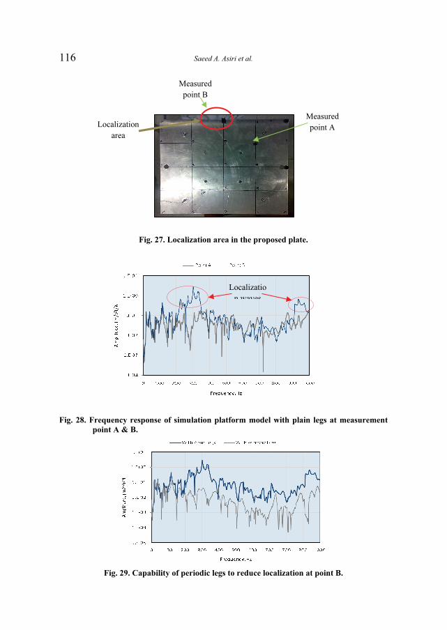
Saeed A. Asiri et al. 116
Fig. 27. Localization area in the proposed plate.
Fig. 28. Frequency response of simulation platform model with plain legs at measurement
point A & B.
Fig. 29. Capability of periodic legs to reduce localization at point B.
Measured
point A
Measured
point B
Localization
area
Localizatio
n waves

Dynamic Response of an Experimental Model… 117
Fig. 30. Accelerometer setting in lateral direction.
In nature, water waves are normally generated by wind blowing over
the water surface and continue to exist after the wind has ceased to affect
them. Offshore platforms are usually located in hostile environments.
These platforms undergo excessive vibrations due to water wave loads
for both normal operating and extreme conditions. To ensure safety, the
lateral displacements of the platforms need to be limited, whereas for the
comfort of people who work at the structures, accelerations also need to
be restricted. In the extreme condition, the amplitude of water waves may
reach high levels caused by the lateral displacement of the offshore
platform. Thus the damages may occur especially in the large sea or
ocean. So, creation of the extreme wave filter may be considered. The
periodic structures technique may be efficient to act as the wave filter
under extreme condition.
Figures 31-33 illustrate the capability of periodic legs to act as a filters
and vibration isolators for lateral displacement. Also and as previously
described, a large number of cells may produce a better isolation.
Fig. 31. The frequency response of the platform model with 3 cells periodic legs in lateral
direction.

Saeed A. Asiri et al. 118
Fig. 32. The frequency response of the platform model with 4 cells periodic legs in lateral
direction.
Fig. 33. The frequency response of the platform model with 5 cells periodic legs in lateral
direction.
5. Conclusions and Recommendations
In this paper, the effectiveness of the periodic beam structures, with
different configurations, in damping vibrations was demonstrated using
various experimental and numerical models. Further, the periodic beam
has shown high ability to attenuate vibrations over broad frequency
bands.
The theoretical equations that govern the operation of this class of
periodic beam are developed using the transfer matrix method. The basic
characteristics of the transfer matrices of periodic legs are presented and
related to the physics of wave propagation along these legs. The effect of

Dynamic Response of an Experimental Model… 119
the design parameters of the periodic legs on their dynamic behavior is
investigated for legs with geometry and material discontinuities. The
theoretical work is modeled as experimental work and it found the
experimental identical with the theoretical concept.
A simulation model of offshore platform was fabricated to provide a
better understanding of wave mechanics in the legs with different cells
number. Two main cases of experimental testing were studied, axial
direction experimental testing and lateral direction experimental testing.
The periodic legs can block the propagation of waves over specified
frequency band extending in most of the considered cases between 16 to
100 Hz and 200 to 1000 Hz. The experimental model was tested at
measurement points which were located at the middle of one edge. The
tests were conducted with different cell numbers of periodic legs and
compared with plain legs. The results showed the capability of periodic
legs to decrease the vibration on the plate over a specified frequency
band in axial and lateral displacements of the plate. Also the periodicity
can help eliminate the localization of waves over some areas of the
studied plate.
In all the results presented in this thesis, it is demonstrated that the
periodic beam can provide attenuations over broad frequencies.
This paper has presented the fundamentals and basics for designing a
new class of legs for offshore platforms. However, the experiments
conducted here were limited to laboratory conditions on a simulation
model of the offshore platform. Work is therefore needed to extend the
applicability of the periodicity approach to real platforms in order to
control the vibration transmission.
The offshore platform is a huge structure and there are many sources
of vibration which may have an effect on it due to operation, machinery
and environments factors as presented. So, the periodic structure can be
employed in different cases and applications to ensure the vibration
control of the offshore platforms to avoid the failures of structures,
equipments, and oil piping. Thus this technique can ensure the
comfortable work environments on the offshore platform. Applying
periodic structures in offshore platform has opened the door for a rich
field of research to study the periodic structure using possibility
especially for the critical vibration problems. The periodic structures

Saeed A. Asiri et al. 120
concepts can be easily implemented for the control of vibration
transmission in many types of applications. And this implementation is
not limited by structure size and location. But, the necessary part of this
implementation is how to redesign and modify existing platform
structures to take full advantage of the benefits of periodic legs.
References
[1] Mead, D.J., ‘‘Wave Propagation in Continuous Periodic Structures: Research
Contributions from Southampton’’, J. Sound Vib., 190: 495-524 (1996).
[2] Ungar, E.E., “Steady-State Response of One-Dimensional Periodic Flexural Systems,” The
Journal of The Acoustic Society of America, 39(5): 887-894 (1966).
[3] Gupta, G.S., “Natural Flexural Waves and The Normal Modes of Periodically Supported
Beams and Plates,” Journal of Sound and Vibration, 13(1): 89-101 (1970).
[4] Faulkner, M.G. and Hong, D.P., “Free Vibration of Mono-Coupled Periodic System,”
Journal of Sound and Vibration, 99(1): 29-42 (1985).
[5] Mead, D.J. and Yaman, Y., “The Response of Infinite Periodic Beams to Point Harmonic
Forces: A Flexural Wave Analysis,” Journal of Sound and Vibration, 144(3): 507-530
(1991).
[6] Mead, D.J., White, R.G. and Zhang, X.M., “Power Transmission In a Periodically
Supported Infinite Beam Excited at A Single Point,” Journal of Sound and Vibration, 169
(4): 558-561 (1994).
[7] Langely, R.S., “Power Transmission in a One-Dimensional Periodic Structure Subjected to
Single-Point Excitation,” Journal of Sound and Vibration, 185 (3): 552-558 (1995).
[8] Langley, R.S., “On The Forced Response of One-Dimensional Periodic Structures:
Vibration Localization by Damping,” Journal of Sound and Vibration, 178(3): 411-428
(1994).
[9] Gry, L. and Gontier, C., “Dynamic Modeling of Railway Track: A Periodic Model Based
on A Generalized Beam Formulation,” Journal of Sound and Vibration, 199(4): 531-558
(1997).
[10] Kissel, G.J., “Localization Factor for Multichannel Disordered Systems,” Physical Review
A, 44(2): 1008-1014 (1991).
[11] Ariaratnam, S.T. and Xie, W.C., “Wave Localization in Randomly Disordered Nearly
Periodic Long Continuous Beams,” Journal of Sound and Vibration, 181(1): 7-22 (1995).
[12] Cetinkaya, C., “Localization of Longitudinal Waves in Bi-Periodic Elastic Structures with
Disorders,” Journal of Sound and Vibration, 221(1): 49-66 (1999).
[13] Xu, M.B. and Huang L., “Control of Multi-Span Beam Vibration by A Random Wave
Reflector,” Journal of Sound and Vibration, 250(4): 591-608 (2002).
[14] Ruzzene, M. and Baz, A., “Attenuation and Localization of Wave Propagation in Periodic
Rods Using Shape Memory Inserts,” Smart Materials and Structures, 9(6): 805-816 (2000).
[15] Ruzzene, M. and Baz, A., “Active Control of Wave Propagation in Periodic Fluid-Loaded
Shells,” Smart Materials and Structures, 10(5): 893-906 (2001).
[16] Thorp, O., Ruzzene, M. and Baz, A., “Attenuation and Localization of Waves in Rods
with Periodic Shunted Piezo,” Smart Materials and Structures, 10(5): 979-989 (2001).
[17] Asiri, S., Baz, A. and Pines, D. “Periodic Struts for Gearbox Support System”, Journal of
Vibration and Control, 11(6): 709-721 (2005).
[18] Asiri, S. and Aljawi, A. “Periodic mounts to Isolate Vibrations of Automotive Vehicle
Engine”, Smart Structures and Materials, 17 (1): 97-115 (2006).

Dynamic Response of an Experimental Model… 121
�� ����� ��� � ������� ����� � ���������� �������
������ ����� ������� �!�"�
������ ��������� ��� ���� ����� �����
��� ����� ��� ������ ���� ��������� – ������ ����
���� ����� ��� ���� - ������ ������ �������
������� . ���� ����� � ��� � �� �� ���� � �
������ ��� ��� ����� �!� �!� � ����"#� �!$��� . %� &
�!$��� '(!�) �*�� � +!�, � +!��-� ������ /,� 0��
%�)��!� ������ �1" � � 2!3� %4���� ��5�4 !3�6) �!� ��
� ��� ��� 7� �48� !���� �! �� .
������� �!4!� %� & �,� 7��� 9����� :1 � ;!�� <��� �� �!��� �� 9(! 0� 9* � = �5���� /,� 94!�� :1 � %,� :� > �4 ����� 0��� �!� :� > �4�� 2�5,�)
���� . �!�4� �� %�)��?� :1 �,� ��������� ������ ;���� %� & %� ��!� 9* !3���!$ ������!3 �)�� .4@� ������ A(!��
�,$�� �� �!� �� ��"� �,� ����� � ��� ��& ����������!� �� :� > � � !$�� !"��� . ����,� A(!���� ���!$ %� &
! 3��� <*�� /!�" �!4 ���-��� ��������� . !�� � & $* �B��)>��� �� ���$��� ���-��� ��������� ���������� ������ � �� ��� �
� ���� ����� ��.