dynamic modeling and control of an integrated solid ... modeling and control of an integrated solid...
TRANSCRIPT

Dynamic Modeling and Control of an Integrated Solid
Sorbent Based CO2 Capture Process
Benjamin Omella, Debangsu Bhattacharyyaa, Stephen E. Zitneyb, David C. Millerc
a Department of Chemical Engineering, West Virginia University, Morgantown, WV 26506, USA b National Energy Technology Laboratory, Morgantown, WV 26507, USA
cNational Energy Technology Laboratory, 626 Cochrans Mill Rd, Pittsburgh, PA 15236, USA
AICHE Annual Meeting 2014
Atlanta, GA

2
MOTIVATION
Under the auspices of US DOE’s Carbon Capture
Simulation Initiative (CCSI), government and university
researchers are collaborating to develop computational
models and tools for various post-combustion CO2
capture technologies
As part of this project, our current focus is on the
development of dynamic models and control systems for
solid-sorbent CO2 capture processes.

3
Post- Combustion Solid Sorbent CO2
Capture
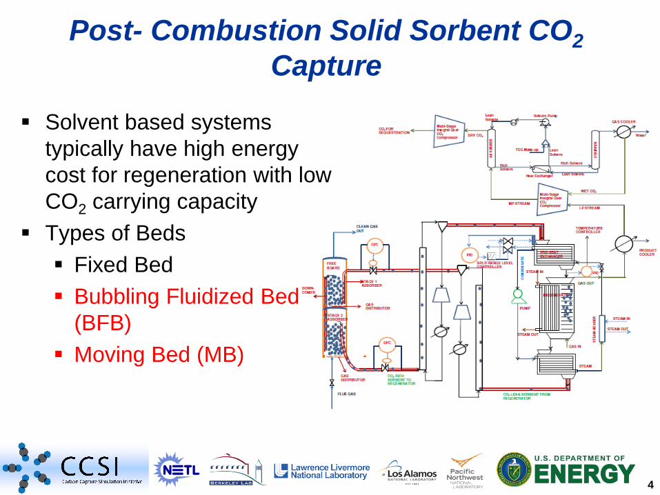
Solvent based systems
typically have high energy
cost for regeneration with low
CO2 carrying capacity
Types of Beds
Fixed Bed
Bubbling Fluidized Bed
(BFB)
Moving Bed (MB)
4
Post- Combustion Solid Sorbent CO2
Capture
Solvent based systems
typically have high energy
cost for regeneration with low
CO2 carrying capacity
Types of Beds
Fixed Bed
Bubbling Fluidized Bed
(BFB)
Moving Bed (MB)

5
Model Assumptions
• Vertical shell & tube type reactor
• Mass balance modeled as plug
flow
• Particles are uniformly dispersed
through the reactor with constant
voidage
• Particle attrition ignored
• Temperature is uniform within
the particles
Model Development for BFB and MB
Solid In
Solid Out
Gas In
Gas Out
Utility In
Utility Out
1-D, two-phase, pressure-driven and non-isothermal
model developed in both ACM and gPROMS

6
• Gaseous species : CO2, N2, H2O
• Solid phase components:
bicarbonate, carbamate, and
physisorbed water.
• Stripping steam is used for
regenerator
• Solid Sorbent: NETL 32D, a
mesoporous amine-impregnated
silica substrate
Components in BFB and MB
Solid In
Solid Out
Gas In
Gas Out
Utility In
Utility Out
7
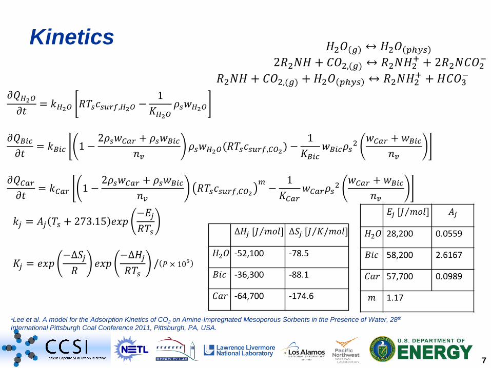
𝜕𝑄𝐻2𝑂
𝜕𝑡= 𝑘𝐻2𝑂 𝑅𝑇𝑠𝑐𝑠𝑢𝑟𝑓,𝐻2𝑂 −
1
𝐾𝐻2𝑂𝜌𝑠𝑤𝐻2𝑂
𝜕𝑄𝐵𝑖𝑐
𝜕𝑡= 𝑘𝐵𝑖𝑐 1 −
2𝜌𝑠𝑤𝐶𝑎𝑟 + 𝜌𝑠𝑤𝐵𝑖𝑐
𝑛𝑣𝜌𝑠𝑤𝐻2𝑂(𝑅𝑇𝑠𝑐𝑠𝑢𝑟𝑓,𝐶𝑂2) −
1
𝐾𝐵𝑖𝑐𝑤𝐵𝑖𝑐𝜌𝑠
2𝑤𝐶𝑎𝑟 + 𝑤𝐵𝑖𝑐
𝑛𝑣
𝜕𝑄𝐶𝑎𝑟
𝜕𝑡= 𝑘𝐶𝑎𝑟 1 −
2𝜌𝑠𝑤𝐶𝑎𝑟 + 𝜌𝑠𝑤𝐵𝑖𝑐
𝑛𝑣𝑅𝑇𝑠𝑐𝑠𝑢𝑟𝑓,𝐶𝑂2
𝑚−
1
𝐾𝐶𝑎𝑟𝑤𝐶𝑎𝑟𝜌𝑠
2𝑤𝐶𝑎𝑟 + 𝑤𝐵𝑖𝑐
𝑛𝑣
Kinetics
𝑘𝑗 = 𝐴𝑗 𝑇𝑠 + 273.15 𝑒𝑥𝑝−𝐸𝑗
𝑅𝑇𝑠
𝐾𝑗 = 𝑒𝑥𝑝−∆𝑆𝑗
𝑅𝑒𝑥𝑝
−∆𝐻𝑗
𝑅𝑇𝑠/ 𝑃 × 105
∆𝐻𝑗 [𝐽 𝑚𝑜𝑙 ] ∆𝑆𝑗 [𝐽 𝐾/𝑚𝑜𝑙 ]
𝐻2𝑂 -52,100 -78.5
𝐵𝑖𝑐 -36,300 -88.1
𝐶𝑎𝑟 -64,700 -174.6
𝐸𝑗 [𝐽 𝑚𝑜𝑙 ] 𝐴𝑗
𝐻2𝑂 28,200 0.0559
𝐵𝑖𝑐 58,200 2.6167
𝐶𝑎𝑟 57,700 0.0989
𝑚 1.17
*Lee et al. A model for the Adsorption Kinetics of CO2 on Amine-Impregnated Mesoporous Sorbents in the Presence of Water, 28th
International Pittsburgh Coal Conference 2011, Pittsburgh, PA, USA.
𝐻2𝑂 𝑔 ↔ 𝐻2𝑂 𝑝ℎ𝑦𝑠
2𝑅2𝑁𝐻 + 𝐶𝑂2,(𝑔) ↔ 𝑅2𝑁𝐻2+ + 2𝑅2𝑁𝐶𝑂2
−
𝑅2𝑁𝐻 + 𝐶𝑂2,(𝑔) +𝐻2𝑂 𝑝ℎ𝑦𝑠 ↔ 𝑅2𝑁𝐻2+ + 𝐻𝐶𝑂3
−

8
MB Step Test- Sorbent Temperature

9
Limitations of Gas Throughput in the MB
𝑈𝑐
𝑔𝐷𝑥
= 0.463𝐴𝑟0.145 𝑣𝑔 < 𝑈𝑐
Limitation in superficial velocity of gas; need to maintain
MB flow regime*
* Chehbouni, et al., The Canadian Journal of Chemical Engineering 1995, 73, 41–50.
• As sorbent is regenerated gas is released increasing the
superficial gas velocity, maximizing at the top of the bed

10
Two-Stage MB Bed
• Sorbent release of CO2 increases
gas flow and velocity at the top of
reactor
• CO2 draw-off between stages
decreases velocity to stay in MB
regime
• Steady-state solution is easily
achieved, but creates a moving
boundary problem for dynamic
operation
• Control strategy required for
solution
Solid in
Stage 1
Stage 2
HX steam
downcomer
CO2 draw-off
Steam Regenerated solids
CO2 to compressor

11
Multi-Stage MB Control Strategy
Stage 1
Stage 2
Flow Regulator
Pressure Regulator
Downcomer
CO2 Draw-off
Level Regulator

12
Response to a 30 second, 22% increase ramp and 10
second, 22% decrease ramp in inlet regeneration steam
Regulation- Steam Ramp
Time Seconds
Se
t P
oin
t
Va
lve
op
en
ing (
%)
Sta
ge
2 o
utlet
pre
ssure
(b
ar)
0.0 25.0 50.0 75.0 100.0 125.0 150.0 175.0 200.0
47.5
52.5
57.5
62.5
1.2
81
.29
1.3
1.3
11
.32
Time Seconds
Se
t P
oin
t km
ol/hr
Va
lve
Op
enin
g %
Inle
t flow
to s
tag
e 1
km
ol/h
r
0.0 25.0 50.0 75.0 100.0 125.0 150.0 175.0 200.04
5.0
50.0
55.0
60.0
65.0
70.0
75.0
85.0
90.0
95.0
100
.01
05
.01
10
.01
15
.0

13
Limitations of MB for Adsorber
𝑈𝑐
𝑔𝐷𝑥
= 0.463𝐴𝑟0.145 𝑣𝑔 < 𝑈𝑐
Limitation in superficial velocity of gas; need to maintain
MB flow regime*
* Chehbouni, et al., The Canadian Journal of Chemical Engineering 1995, 73, 41–50.
• Because of the high amount of N2 in the flue gas, a
prohibitively large bed diameter or a very high number of
parallel beds would be required for a MB adsorber
• Given an adsorber that is treating 2000 mol/s with 12% CO2
and 90% capture rate, 27 MB in parallel with a diameter of
9 m each would be required.

14
Bubbling Fluidized Bed
Similar assumptions as the
moving bed
Flexible steady-state and
dynamic models that can be
used for both adsorber or
regenerator, with
underflow/overflow-type
configurations

15
Dynamic Results – Increase Inlet Gas
Flow by 20.6%
Gas CO2 Concentration (ACM) Gas H2O Concentration (ACM)

16
• Any adsorption (or gas separation) process can be applied,
especially for processes for heat input/removal and different
flow configurations.
– Moisture removal
– Natural gas processing
– Hydrogen purification
– Novel solid sorbent processes
– etc.
• These models can be adapted to other applications by:
– Define new components and update physical properties
– Input new reaction kinetic model/data
Applications of the BFB and MB Models
Other than CO2 Capture

17
CO2 Compression Model
Compressor stages 7-8 A
bso
rbe
r
Str
ipp
er
CO2 for
sequestration
Dry
CO2
Wet CO2
Solvent
Pump
Make-up
TEG MP CO2 rich
stream
Water
LP CO2 rich stream
from regenerator
Dynamic model of multi-stage integral-gear compression system with inter-
stage coolers and flash vessels, recycle valves for surge control, and TEG
absorber and regenerator

18
0.08 0.1 0.12 0.14 0.16 0.18 0.2 0.22 0.240.4
0.5
0.6
0.7
0.8
0.9
1
1.1
1.2
1.3
Psi3
Ps
i s
-15
0
15
30
40
50
60
70
75
Performance Curves
Dimensionless Performance Curves for
the 1st Stage
• Dimensionless exit flow coefficient
and impeller isentropic head
coefficient for applicability to
varying Mach numbers and inlet
operating conditions

19
Transient Step Response
Transient response in pressure as
a result of 10% ramp increase in
flowrate
Transient response in power as
a result of 10% ramp increase in
flowrate
PRESSURE
Time Hours
Co
mp
_s
tag
e7
.o_
po
rt.P
ba
r
Co
mp
_S
tag
e6
.o_
po
rt.P
ba
r
Co
mp
_S
tag
e5
.o_
po
rt.P
ba
r
Co
mp
_S
tag
e4
.o_
po
rt.P
ba
r
Co
mp
_s
tag
e3
.o_
po
rt.P
ba
r
Co
mp
_s
tag
e2
.o_
po
rt.P
ba
r
Co
mp
_s
tag
e1
.o_
po
rt.P
ba
r
0.0 5.0 10.0 15.0 20.0 25.030.0 35.0 40.045.0 50.0
96.
097.
098.
099.
0100
.0101
.0102
.0
60.
061.
062.
063.
064.
065.
066.
067.
0
36.
037.
038.
039.
040.
041.
042.
0
21.
021.
522.
022.
523.
023.
524.
0
11.
011.
512.
012.
5
5.2
55.5
5.7
56.0
6.2
5
2.4
2.4
52.5
2.5
52.6
2.6
52.7
2.7
5
Time Hours
Com
p_sta
ge8.e
lec_
pow
kW
Com
p_sta
ge7.e
lec_
pow
kW
Com
p_S
tage6.
ele
c_po
w k
W
Com
p_S
tage5.
ele
c_po
w k
W
Com
p_S
tage4.
ele
c_po
w k
W
Com
p_sta
ge3.e
lec_
pow
kW
Com
p_sta
ge2.e
lec_
pow
kW
Com
p_sta
ge1.e
lec_
pow
kW
0.0 20.0 40.0 60.0
16
40
.01
66
0.0
16
80
.0
16
40
.01
68
0.0
17
20
.01
76
0.0
26
00
.02
70
0.0
28
00
.02
90
0.0
24
00
.02
50
0.0
26
00
.02
70
0.0
30
00
.03
10
0.0
32
00
.03
30
0.0
34
00
.0
34
00
.03
60
0.0
38
00
.04
00
0.0
42
00
.04
40
0.0
46
00
.04
80
0.0
50
00
.0
44
00
.04
60
0.0
48
00
.05
00
0.0

20
Integrated Model
• Adsorber
• Bubbling Fluidized Bed (BFB)
• Regenerator
• Moving Bed (MB)
• CO2 Compression
• Balance of Plant
Adsorber
(CO2 Capture)
Solid Sorbent
Regenerator
Balance
of Plant
CO2
Compression
Rich
Sorbent
Flue
Gas
Lean
Sorbent

21
Integrated Process Model
Compressor Train: 8 Stages
TEG Absorber and Stripper Sorbent BFB Adsorber and
MB Regenerator

22
Combined System Model (Single Train)
Regenerated Solids
Top
Adsorber
Bottom
Adsorber
Flue Gas In
Post Heat
Exchanger
Pre Heat
Exchanger
HX steam
CO2 out
Clean Gas Out
Regeneration
Steam
HX steam

23
Inputs and Conditions
MB Variable Base Value Units
Stage Diameter 7 m
Stage Height 2.5 m
Steam inlet flow rate 400 kmol/hr
Solids inlet flow rate 658000 kg/hr
Solids inlet temperature 110 oC
Loading of bicarbonate 0.62 mol/kg sorbent
Loading of carbamate 1.8 mol/kg sorbent
Loading of water 1.03 mol/kg sorbent
BFB Variable Base Value Units
Stage diameter 6 m
Stage height 2.5 m
Steam flue gas rate 400 kmol/hr
Solids inlet flow rate 658000 kg/hr
Solids inlet temperature 60 oC
Loading of bicarbonate 0.25 mol/kg sorbent
Loading of carbamate 1.23 mol/kg sorbent
Loading of water 0.56 mol/kg sorbent

24
Ramp In Flue Gas Example
Flow into compressor train
Time Hours
Inle
t flo
w k
mo
l/h
r
0.0 20.0 40.0
56
00
.05
80
0.0
CO2 % Removed
Time Hours
%
0.0 20.0 40.0-0.2
-0.1
0.0
0.1
0.2
0.3
0.4
Ramp in flue gas
Time=0 : 15.8% increase
Time=20: 28.8% decrease
Time Hours
Co
mp
_sta
ge
8.e
lec_
po
w k
W
Co
mp
_sta
ge
7.e
lec_
po
w k
W
Co
mp
_S
tag
e6
.ele
c_
po
w k
W
Co
mp
_S
tag
e5
.ele
c_
po
w k
W
Co
mp
_S
tag
e4
.ele
c_
po
w k
W
Co
mp
_sta
ge
3.e
lec_
po
w k
W
Co
mp
_sta
ge
2.e
lec_
po
w k
W
Co
mp
_sta
ge
1.e
lec_
po
w k
W
0.0 20.0 40.0
16
40
.0
16
20
.01
64
0.0
16
60
.01
68
0.0
26
20
.02
64
5.0
26
70
.02
69
5.0
24
00
.02
50
0.0
26
00
.0
30
00
.03
10
0.0
32
00
.0
34
00
.03
60
0.0
38
00
.0
42
00
.04
40
0.0
46
00
.0
44
00
.04
60
0.0
48
00
.0

25
Ramp in Regeneration Steam
Time HoursCo
mp
_sta
ge
8.e
lec_
po
w k
W
Co
mp
_sta
ge
7.e
lec_
po
w k
W
Co
mp
_S
tag
e6
.ele
c_
po
w k
W
Co
mp
_S
tag
e5
.ele
c_
po
w k
W
Co
mp
_S
tag
e4
.ele
c_
po
w k
W
Co
mp
_sta
ge
3.e
lec_
po
w k
W
Co
mp
_sta
ge
2.e
lec_
po
w k
W
Co
mp
_sta
ge
1.e
lec_
po
w k
W
0.0 10.0 20.0 30.0 40.0
16
60
.01
68
0.0
17
00
.01
75
0.0
18
00
.0
27
00
.02
80
0.0
29
00
.03
00
0.0
25
00
.02
60
0.0
27
00
.02
80
0.0
32
00
.03
30
0.0
34
00
.0
36
00
.03
80
0.0
40
00
.0
46
00
.04
80
0.0
50
00
.0
46
00
.04
80
0.0
50
00
.0
Flow into compressor train
Time Hours
km
ol/hr
0.0 10.0 20.0 30.0 40.0
6000.0
6200.0 CO2 % removed
Time Hours
%
0.0 10.0 20.0 30.0 40.00.2
50
.275
0.3
0.3
25
0.3
5
Ramp in steam
Time=0: 27% increase

26
Conclusions
• Developed flexible, high-fidelity, first principle, dynamic
bubbling fluidized bed and moving bed solid sorbent
models for CO2 capture and CO2 compression
• Multi-stage moving bed model requires reduced gas
velocity, resulting in a moving boundary problem
• Model can handle common disturbances
• Work still to be done
• Process needs optimization for increase in CO2
removal
• Develop MB model that has several CO2 draw-off
points with advanced process controller
• Develop Reduced order model

27
Acknowledgements : As part of the National Energy Technology Laboratory’s Regional
University Alliance (NETL-RUA), a collaborative initiative of the
NETL, this technical effort was performed under the RES contract
DE-FE0004000.
Disclaimer: This presentation was prepared as an account of work sponsored by an
agency of the United States Government. Neither the United States
Government nor any agency thereof, nor any of their employees, makes
any warranty, express or implied, or assumes any legal liability or
responsibility for the accuracy, completeness, or usefulness of any
information, apparatus, product, or process disclosed, or represents that
its use would not infringe privately owned rights. Reference herein to any
specific commercial product, process, or service by trade name,
trademark, manufacturer, or otherwise does not necessarily constitute or
imply its endorsement, recommendation, or favoring by the United States
Government or any agency thereof. The views and opinions of authors
expressed herein do not necessarily state or reflect those of the United
States Government or any agency thereof.