dynamic comparators - iowa state universityclass.ece.iastate.edu/ee435/lectures/dynamic...
TRANSCRIPT
Dynamic Comparators
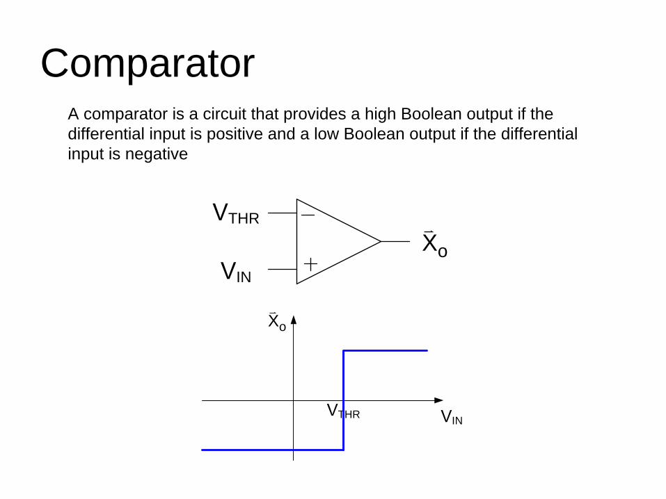
ComparatorA comparator is a circuit that provides a high Boolean output if the differential input is positive and a low Boolean output if the differential input is negative
IN
THR
oX
INTHR
oX
Comparator
IN
THR
oX
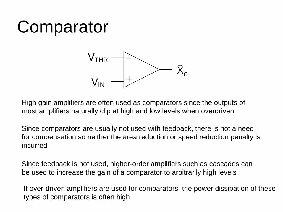
High gain amplifiers are often used as comparators since the outputs of most amplifiers naturally clip at high and low levels when overdriven
Since comparators are usually not used with feedback, there is not a need for compensation so neither the area reduction or speed reduction penalty is incurred
Since feedback is not used, higher-order amplifiers such as cascades can be used to increase the gain of a comparator to arbitrarily high levels
If over-driven amplifiers are used for comparators, the power dissipation of these types of comparators is often high
Comparator
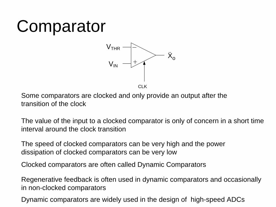
Some comparators are clocked and only provide an output after the transition of the clock
The value of the input to a clocked comparator is only of concern in a short time interval around the clock transition
The speed of clocked comparators can be very high and the power dissipation of clocked comparators can be very low
Clocked comparators are often called Dynamic Comparators
IN
THR
oX
CLK
Dynamic comparators are widely used in the design of high-speed ADCs
Regenerative feedback is often used in dynamic comparators and occasionally in non-clocked comparators
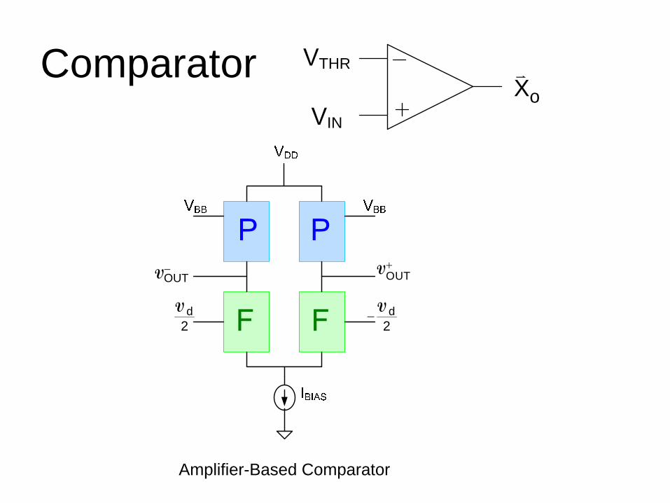
ComparatorIN
THR
oX
OUT+V
OUT−V
d2
V d2
−V
Amplifier-Based Comparator
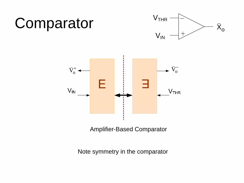
ComparatorIN
THR
oX
Amplifier-Based Comparator
oV+oV−
Note symmetry in the comparator
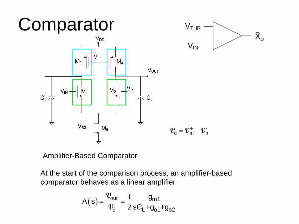
ComparatorIN
THR
oX
Amplifier-Based Comparator
At the start of the comparison process, an amplifier-based comparator behaves as a linear amplifier
( ) out
d
12
m1
L o1 o2
gA ssC +g +g
= =V
V
d-
in in= −+V V V
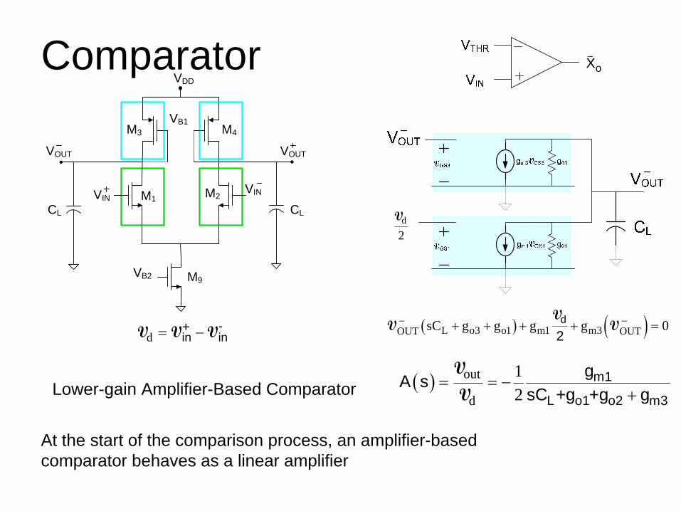
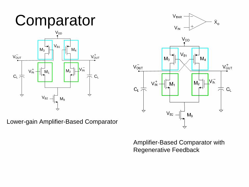
Comparator oX
Lower-gain Amplifier-Based Comparator
At the start of the comparison process, an amplifier-based comparator behaves as a linear amplifier
( ) out
d
12
m1
L o1 o2 m3
gA ssC +g +g g
= = −+
V
V
d-
in in= −+V V V
VDD
VB1
M1 M2
VB2
M3 M4
VINVIN
M9
CLCL
VOUTVOUT
d
2V
( ) ( )L o3 o1 m1 m3OUT OUTsC g g g g 0d
2− −+ + + + =
VV V
Comparator oX
Lower-gain Amplifier-Based Comparator
VDD
VB1
M1 M2
VB2
M3 M4
VINVIN
M9
CLCL
VOUTVOUT
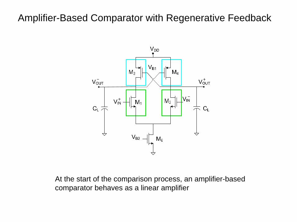
Amplifier-Based Comparator with Regenerative Feedback
Amplifier-Based Comparator with Regenerative Feedback
At the start of the comparison process, an amplifier-based comparator behaves as a linear amplifier
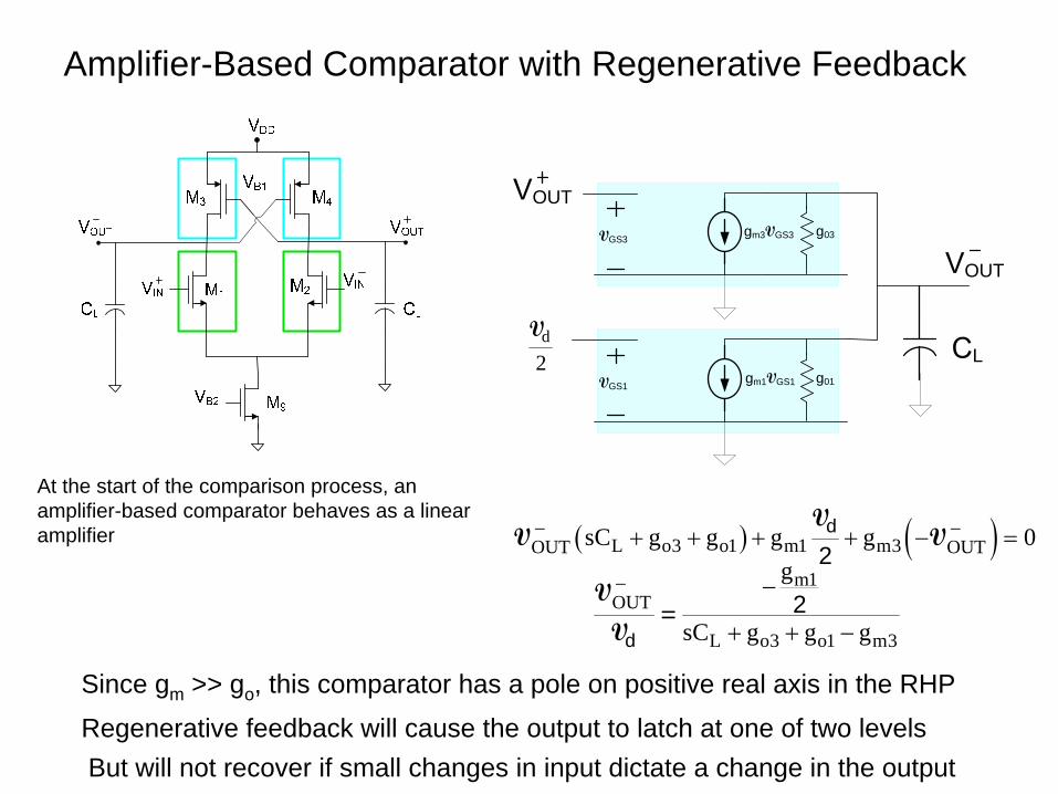
Amplifier-Based Comparator with Regenerative Feedback
At the start of the comparison process, an amplifier-based comparator behaves as a linear amplifier
gm1VGS1VGS1g01
gm3VGS3VGS3g03
d
2V
OUT
L
OUT
( ) ( )L o3 o1 m1 m3OUT OUTsC g g g g 0d
2− −+ + + + − =
VV V
m1OUT
L o3 o1 m3
g
sC g g gd
2− −
+ + −
V=
V
Since gm >> go , this comparator has a pole on positive real axis in the RHP
Regenerative feedback will cause the output to latch at one of two levelsBut will not recover if small changes in input dictate a change in the output
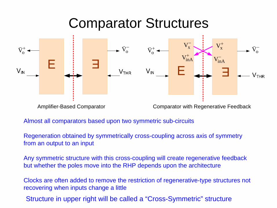
Comparator Structures
oV+oV−
oV+oV−xV−
xV+
inAV−inAV+
Amplifier-Based Comparator Comparator with Regenerative Feedback
Almost all comparators based upon two symmetric sub-circuits
Regeneration obtained by symmetrically cross-coupling across axis of symmetry from an output to an input
Any symmetric structure with this cross-coupling will create regenerative feedback but whether the poles move into the RHP depends upon the architecture
Clocks are often added to remove the restriction of regenerative-type structures not recovering when inputs change a little
Structure in upper right will be called a “Cross-Symmetric” structure
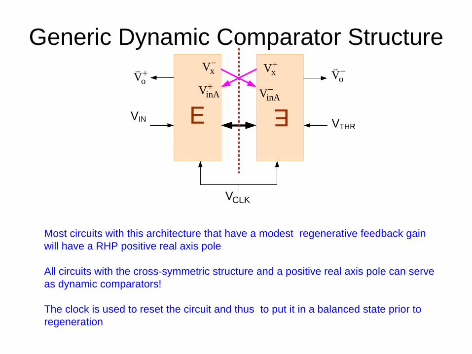
Generic Dynamic Comparator Structure
Most circuits with this architecture that have a modest regenerative feedback gain will have a RHP positive real axis pole
All circuits with the cross-symmetric structure and a positive real axis pole can serve as dynamic comparators!
The clock is used to reset the circuit and thus to put it in a balanced state prior to regeneration
IN
oV+oV−
THR
xV−xV+
inAV−inAV+
CLKV
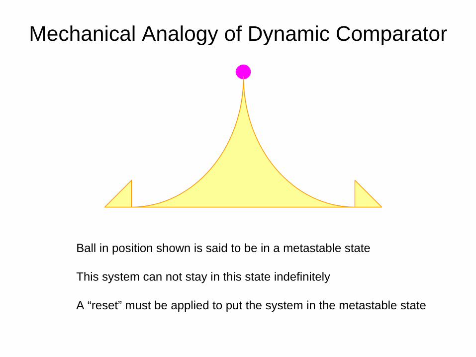
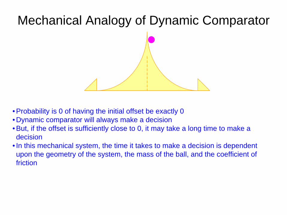
Mechanical Analogy of Dynamic Comparator
Ball in position shown is said to be in a metastable state
This system can not stay in this state indefinitely
A “reset” must be applied to put the system in the metastable state
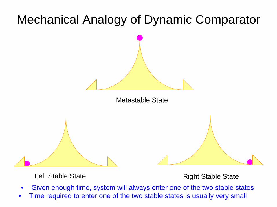
Mechanical Analogy of Dynamic Comparator
Right Stable StateLeft Stable State
• Given enough time, system will always enter one of the two stable states• Time required to enter one of the two stable states is usually very small
Metastable State
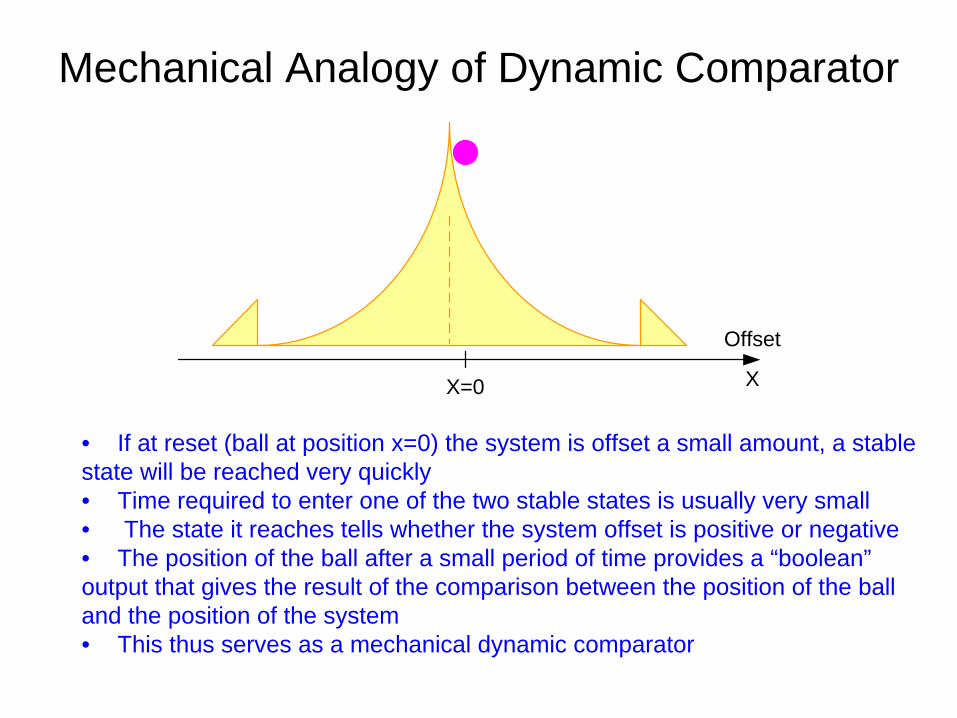
Mechanical Analogy of Dynamic Comparator
• If at reset (ball at position x=0) the system is offset a small amount, a stable state will be reached very quickly• Time required to enter one of the two stable states is usually very small• The state it reaches tells whether the system offset is positive or negative• The position of the ball after a small period of time provides a “boolean” output that gives the result of the comparison between the position of the ball and the position of the system• This thus serves as a mechanical dynamic comparator
Offset
X=0 X
Mechanical Analogy of Dynamic Comparator
• Probability is 0 of having the initial offset be exactly 0• Dynamic comparator will always make a decision• But, if the offset is sufficiently close to 0, it may take a long time to make a decision
• In this mechanical system, the time it takes to make a decision is dependent upon the geometry of the system, the mass of the ball, and the coefficient of friction
Mechanical Analogy of Dynamic Comparator
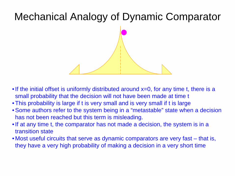
• If the initial offset is uniformly distributed around x=0, for any time t, there is a small probability that the decision will not have been made at time t
• This probability is large if t is very small and is very small if t is large• Some authors refer to the system being in a “metastable” state when a decision has not been reached but this term is misleading.
• If at any time t, the comparator has not made a decision, the system is in a transition state
• Most useful circuits that serve as dynamic comparators are very fast – that is, they have a very high probability of making a decision in a very short time
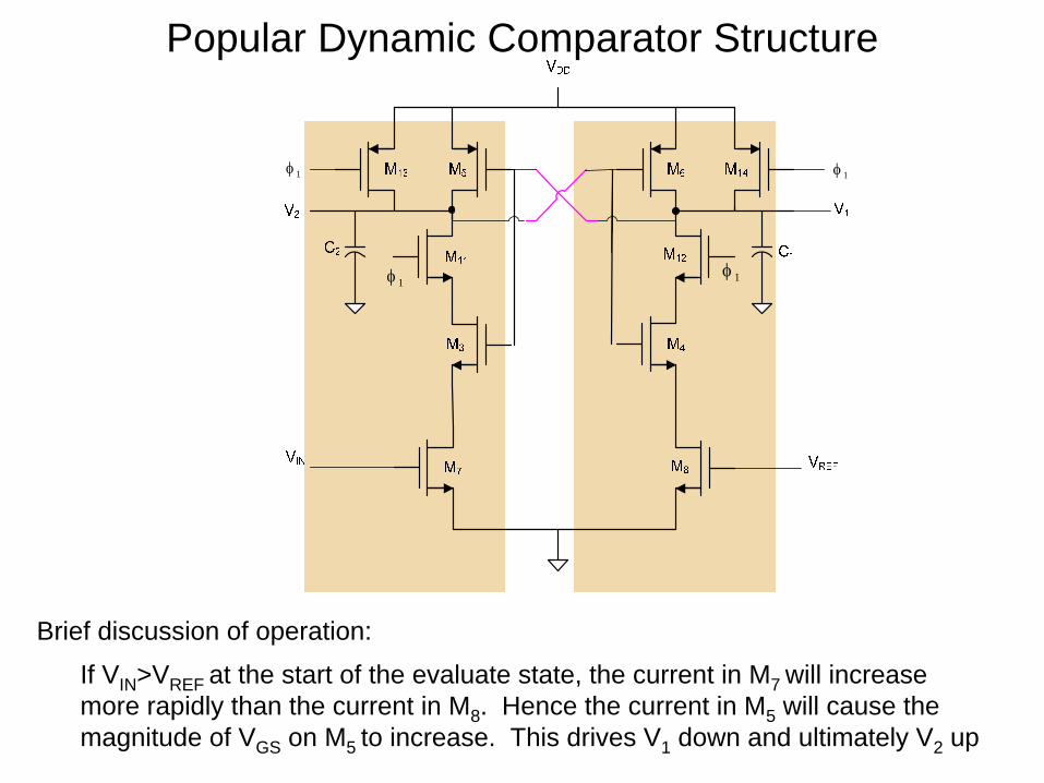
Popular Dynamic Comparator Structure
1φ
1φ 1φ
1φ
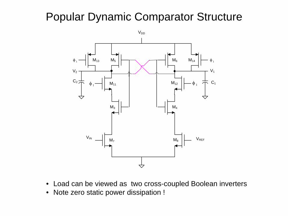
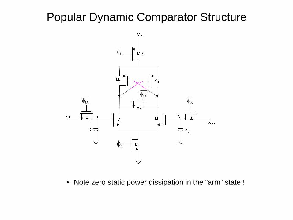
If VIN >VREF at the start of the evaluate state, the current in M7 will increase more rapidly than the current in M8 . Hence the current in M5 will cause the magnitude of VGS on M5 to increase. This drives V1 down and ultimately V2 up
Brief discussion of operation:
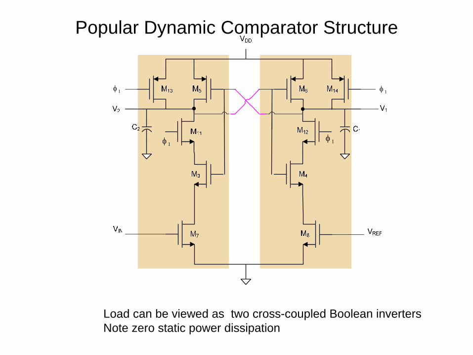
Popular Dynamic Comparator Structure
1φ
1φ 1φ
1φ
Load can be viewed as two cross-coupled Boolean invertersNote zero static power dissipation
Popular Dynamic Comparator Structure
VIN VREF
M3 M4
M5 M6
M7 M8
VDD
C1C2
V1V2
1φ
1φ 1φ
1φM11 M12
M13 M14
• Load can be viewed as two cross-coupled Boolean inverters• Note zero static power dissipation !
Popular Dynamic Comparator Structure
1φ
1φ 1φ
1φ
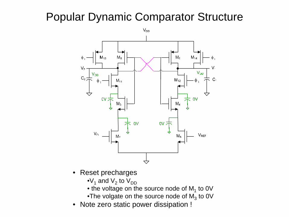
• Reset precharges•V1 and V2 to VDD• the voltage on the source node of M1 to 0V•The volgate on the source node of M3 to 0V
• Note zero static power dissipation !
Popular Dynamic Comparator Structure
1φ
1φ 1φ
1φ
t
VO
VO
VO
VO
H
H
H
L
L
L
CLK
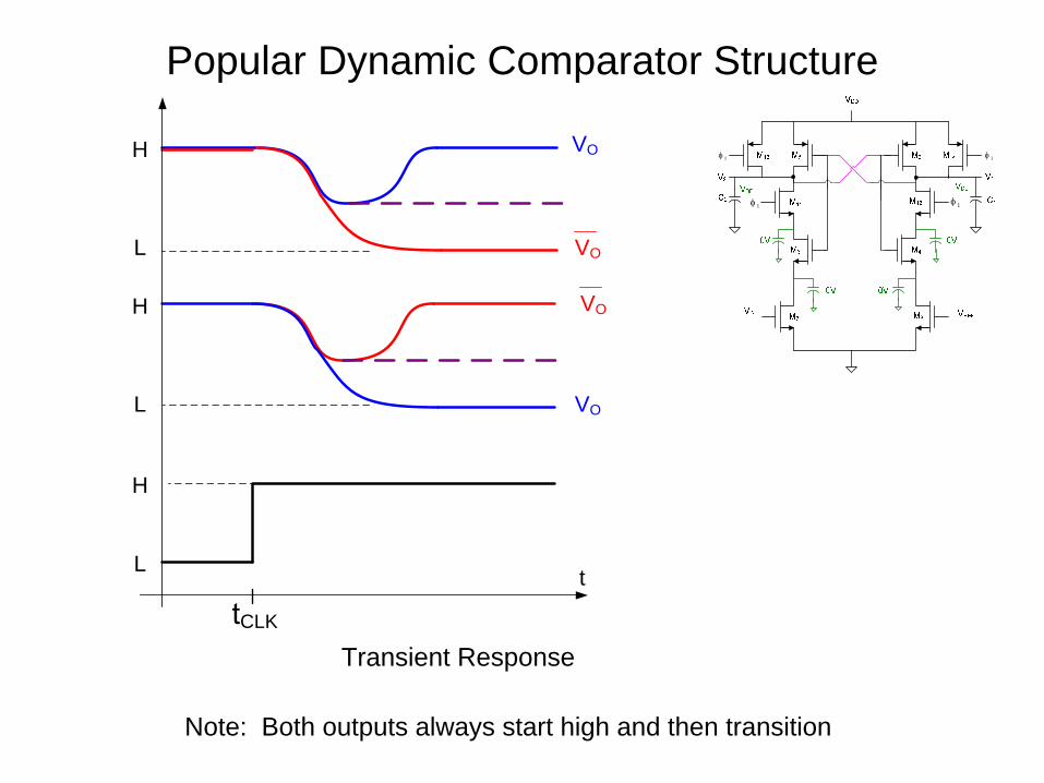
Transient Response
Note: Both outputs always start high and then transition
Popular Dynamic Comparator Structure
1φ
1φ 1φ
1φ
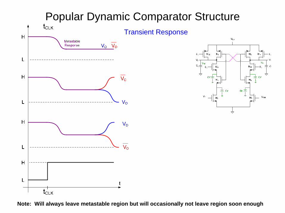
Transient Response
Note: Will always leave metastable region but will occasionally not leave region soon enough
Popular Dynamic Comparator Structure
1φ
1φ 1φ
1φ
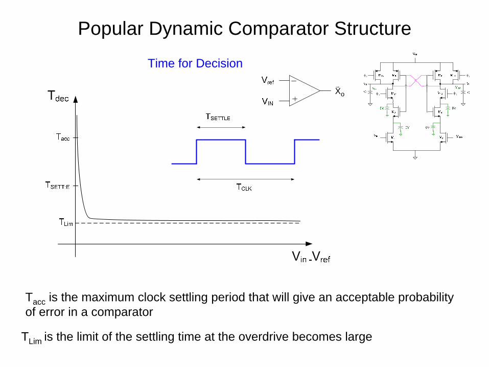
Time for Decision
Tacc is the maximum clock settling period that will give an acceptable probability of error in a comparator
oX
TLim is the limit of the settling time at the overdrive becomes large
Popular Dynamic Comparator Structure
• Note zero static power dissipation in the “arm” state !
1φ
A1φ
1φ
A1φA1φ
Popular Dynamic Comparator Structure
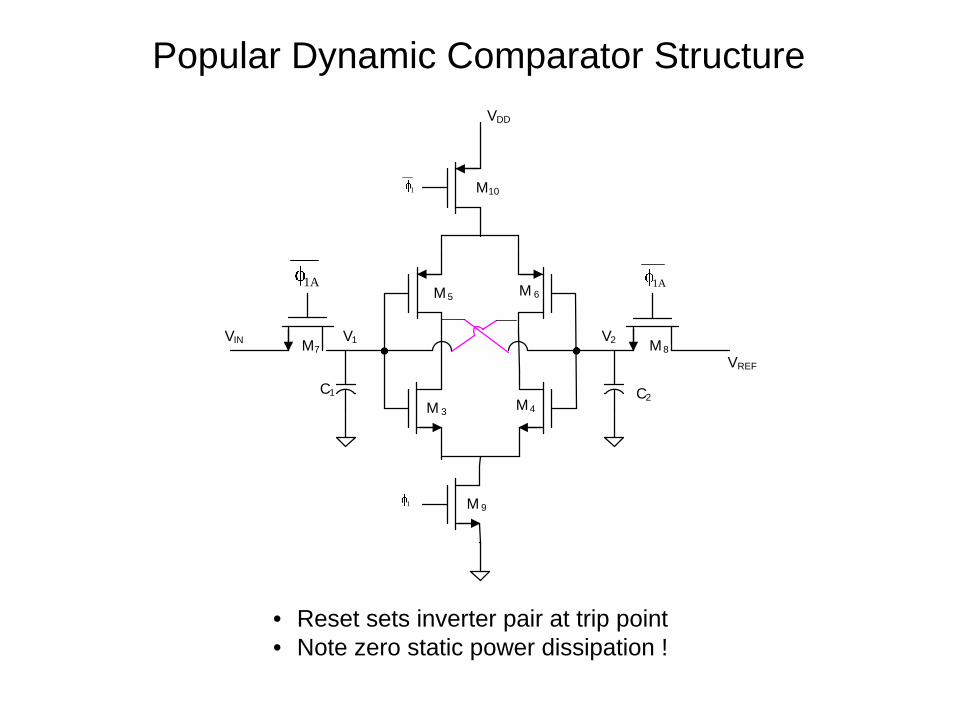
• Reset sets inverter pair at trip point • Note zero static power dissipation !
VIN
VREF
M 3 M4
M5 M 6
M7 M8
M 9
M10
VDD
1
A1
1
C1 C2
V1 V2
A1
Popular Dynamic Comparator Structure
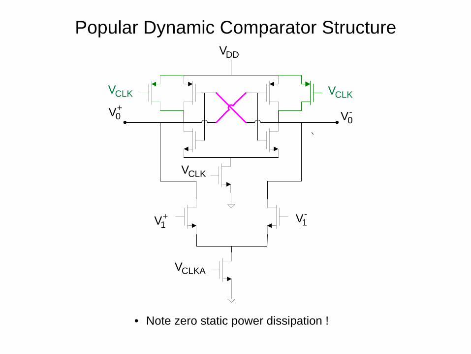
• Note zero static power dissipation !
+0V -
0V
+1V -
1V
CLKV
CLKV
CLKAV
DDV
CLKV
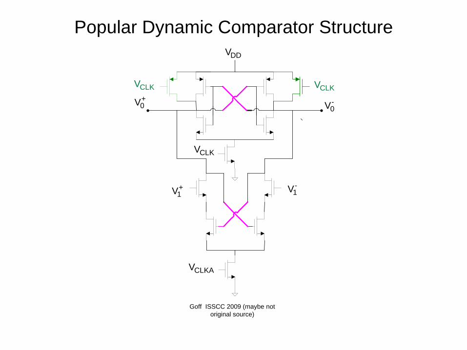
Popular Dynamic Comparator Structure
+0V -
0V
+1V -
1V
CLKV
CLKV
CLKAV
DDV
Goff ISSCC 2009 (maybe not original source)
CLKV
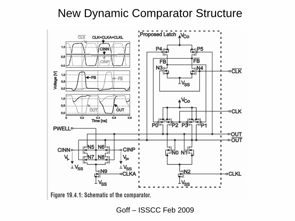
New Dynamic Comparator Structure
Goff – ISSCC Feb 2009
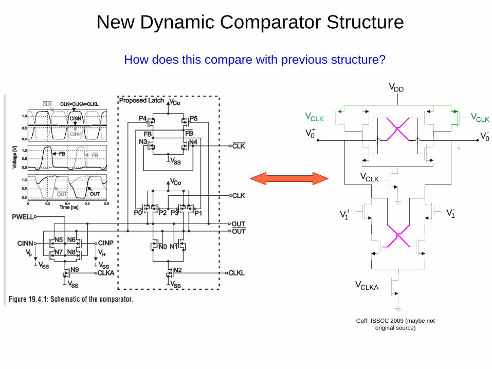
New Dynamic Comparator Structure
+0V -
0V
+1V -
1V
CLKV
CLKV
CLKAV
DDV
Goff ISSCC 2009 (maybe not original source)
CLKV
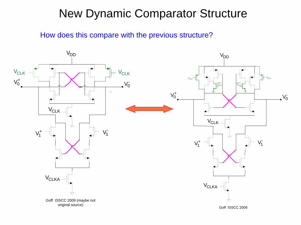
How does this compare with previous structure?
New Dynamic Comparator Structure
+0V -
0V
+1V -
1V
CLKV
CLKAV
DDV
CLKV
CLKV CLKV
CLKV
Goff ISSCC 2009
redraw as:
New Dynamic Comparator Structure
+0V -
0V
+1V -
1V
CLKV
CLKAV
DDV
CLKV
CLKV CLKV
CLKV
Goff ISSCC 2009
How does this compare with the previous structure?
+0V -
0V
+1V -
1V
CLKV
CLKV
CLKAV
DDV
Goff ISSCC 2009 (maybe not original source)
CLKV
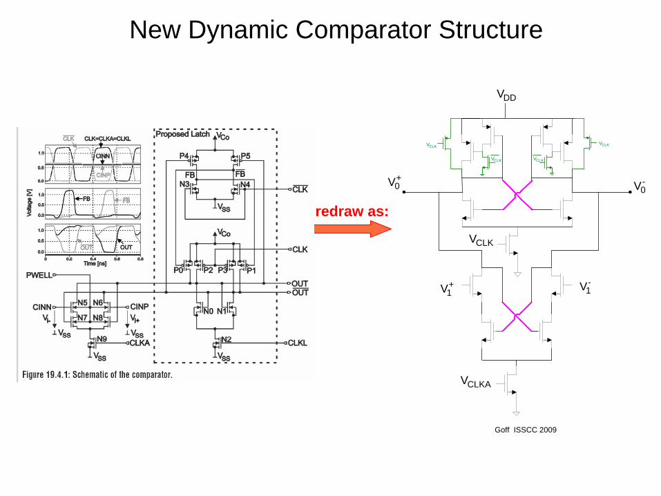
New Dynamic Comparator Structure
+0V -
0V
+1V -
1V
CLKV
CLKAV
DDV
CLKV
CLKV CLKV
CLKV
Goff ISSCC 2009
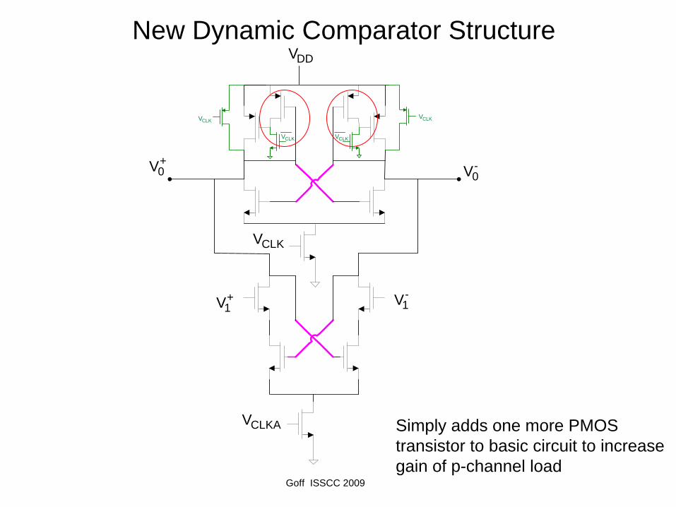
Simply adds one more PMOS transistor to basic circuit to increase gain of p-channel load
New Dynamic Comparator Structure
+0V -
0V
+1V -
1V
CLKV
CLKAV
DDV
CLKV
CLKV CLKV
CLKV
Goff ISSCC 2009
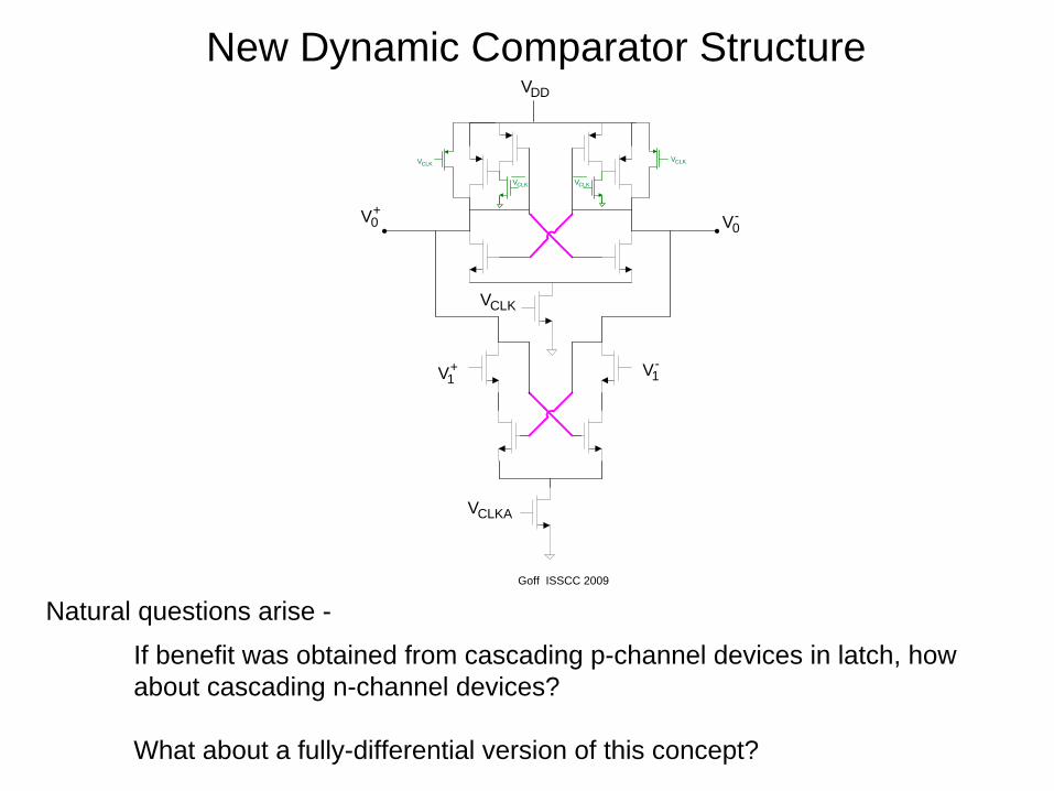
Natural questions arise -
If benefit was obtained from cascading p-channel devices in latch, how about cascading n-channel devices?
What about a fully-differential version of this concept?
+1V -
1V
+1V -
1V
-0V
+0V
+1V -
1V
+2V -
2V
-0V
+0V
xV−xV+
inAV−inAV+
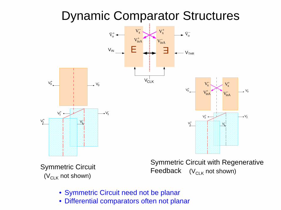
Dynamic Comparator Structures
Symmetric CircuitSymmetric Circuit with Regenerative Feedback
VIN
oV+oV−
VTHR
xV−xV+
inAV−inAV+
CLKV
(VCLK not shown)(VCLK not shown)
• Symmetric Circuit need not be planar • Differential comparators often not planar
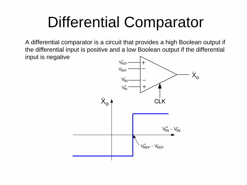
Differential ComparatorA differential comparator is a circuit that provides a high Boolean output if the differential input is positive and a low Boolean output if the differential input is negative
oX+INV
-INV
+REFV-REFV
oX
+ -IN INV V−
+ -REF REFV V−
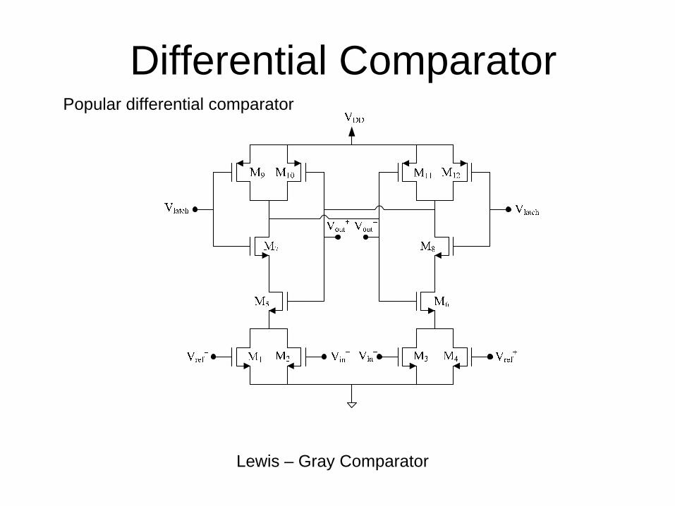
Differential ComparatorPopular differential comparator
Lewis – Gray Comparator
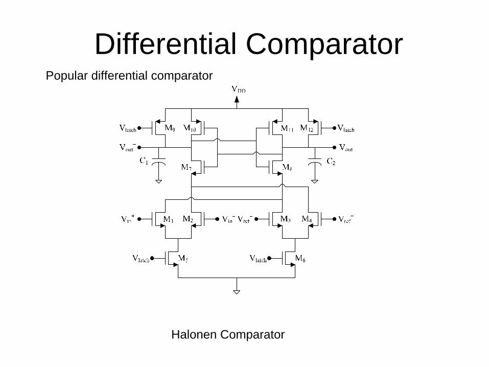
Differential ComparatorPopular differential comparator
Halonen Comparator

Differential ComparatorPopular differential comparator
Halonen Comparator
+0V
+1V
-2V
-1V
+2V
CLKV
CLKV
CLKV
DDV
-0V
CLKV

Differential ComparatorPopular differential comparator
Katyal Comparator
M3
M7
M4
M11
C1 C2
VDD
Vin+ VinVref
+ Vref
Vlatch
Vlatch Vlatch
M1 M2
M5 M6
M8
M9 M10 M12
Vout+ Vout
Vlatch

Dynamic Comparator Opportunities
• Dynamic Comparators can easily be designed
• Likely some of best structures have not evolved
• Symmetric circuit with regenerative feedback gives opportunity to identify new structures that may be particularly useful
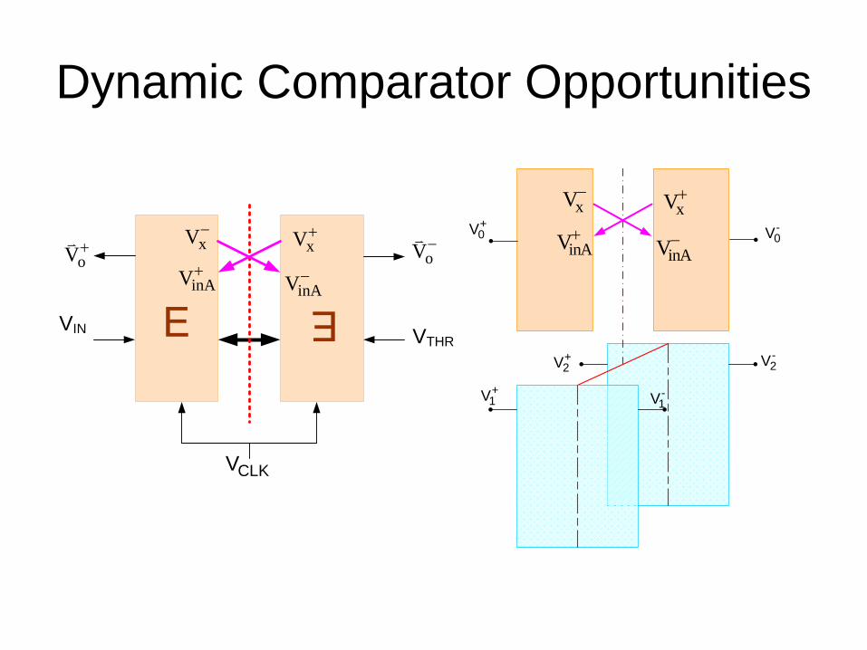
Dynamic Comparator Opportunities
+1V -
1V
+2V -
2V
-0V
+0V
xV−xV+
inAV−inAV+
VIN
oV+oV−
VTHR
xV−xV+
inAV−inAV+
CLKV