dynamic analysis and field balancing of 70 mw gas-turbine ... · dynamic analysis and field...
TRANSCRIPT

DYNAMIC ANALYSIS And FIELD BALANCINGof
70 MW GAS-TURBINE GENERATORS
E. J. GunterR.R. Humphris
Department of Mechanical Engineering & Aerospace EngineeringUniversity of Virginia
Charlottesville, Virginia 22903
Dyrobes Rotordynamics Softwarehttp://dyrobes.com

I. INTRODUCTION and BACKGROUND
This paper summarizes the multi-plane balancing procedure and dynamic characteristics experienced with several 70 MW gas turbine-generator sets. The gas turbine is a W501 class and weighs approximately 72,000 Lb, and the generator weighs approximately 51,000 Lb. There are two bearings supporting the gas turbine and three bearings supporting the generator. The generator and gas turbine are connected by a rigid coupling.
The W501 gas turbine has had a previous history of high vibrations during cold and hot starts. Thermal bowing of the rotor under load normally occurs with this class of
rotor. The bowing effect may be attributed to two sources; the expansion of the copper conductors in the generator and the thermal expansion of the gas turbine. In the later case, re-machining of the torque tube has been reported in the literature to have some benefit.
In the first case study, a utility had a particular 70 MW unit that the manufacturer had attempted to balance for three months without success. However, similar units in the same facility did not experience this difficulty. In the first case, the gas turbine appeared to be operating near a third rotor critical speed. Simple two plane balancing, in this case, is not possible and additional balance planes must be employed.
In addition to the turbine appearing to operate near a third critical speed, the turbine-generator response was effected by the power level. Substantial changes in synchronous amplitude and phase occurred along the turbine-generator when the power level was increased from O to 70 MW.
To add to the complexity of the first case, seal rubs were encountered at the exciter under certain unbalance conditions. This would lead to supcrharmonic oscillations of 3x running speed and cause non-linear jumps in amplitude and phase at the exciter end. Under these conditions, the influence coefficients change dramatically along the
entire length of the 60 ton, 55 ft. turbine-generator set.
It was found that proper balancing requires that both no load and full load data be obtained before and after the application of the trial or calibration weights in order to make proper balance predictions. In addition to obtaining data at 3,600 RPM, data should
also be obtained in the 1,000 RPM range and 2,400 RPM range. If one, for example, attempts to trim balance the gas turbine at 3,600 RPM with a static balance (in plane) weight set, then one risks bowing the rotor at its first critical speed around 1,000 RPM. This occurred in one of the earlier balancing attempts on the first unit by the OEM field engineer (Original Equipment Manufacturer).
One of the objectives of the second balancing case, performed by E. Gunter and D. Marshall of S.C.E., was to balance the unit efficiently with the fewest number of runs to a suitable level of vibration so that it would not be necessary to strip down the generator to perform an internal balance on the generator. If the generator is taken off-line and degassed, then this procedure is extremely time-consuming and expensive.
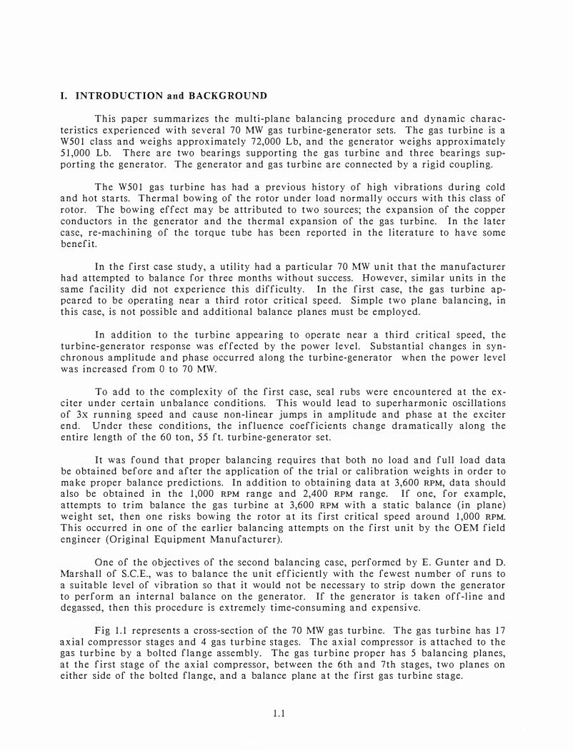
Fig I.I represents a cross-section of the 70 MW gas turbine. The gas turbine has 17 axial compressor stages and 4 gas turbine stages. The axial compressor is attached to the gas turbine by a bolted flange assembly. The gas turbine proper has 5 balancing planes,
at the first stage of the axial compressor, between the 6th and 7th stages, two planes on either side of the bolted flange, and a balance plane at the first gas turbine stage.
1.1
I. INTRODUCTION and BACKGROUND
This paper summarizes the multi-plane balancing procedure and dynamic charac
teristics experienced with several 70 MW gas turbine-generator sets. The gas turbine is a W501 class and weighs approximately 72,000 Lb, and the generator weighs approximately
51,000 Lb. There are two bearings supporting the gas turbine and three bearings sup
porting the generator. The generator and gas turbine are connected by a rigid coupling.
The W501 gas turbine has had a previous history of high vibrations during cold and hot starts. Thermal bowing of the rotor under load normally occurs with this class of
rotor. The bowing effect may be attributed to two sources; the expansion of the copper
conductors in the generator and the thermal expansion of the gas turbine. In the later case, re-machining of the torque tube has been reported in the literature to have some
benefit.
In the first case study, a utility had a particular 70 MW unit that the manufacturer had attempted to balance for three months without success. However, similar units in the same facility did not experience this difficulty. In the first case, the gas turbine appeared to be operating near a third rotor critical speed. Simple two plane balancing, in this case, is not possible and additional balance planes must be employed.
In addition to the turbine appearing to operate near a third critical speed, the
turbine-generator response was effected by the power level. Substantial changes in synchronous amplitude and phase occurred along the turbine-generator when the power level
was increased from O to 70 MW.
To add to the complexity of the first case, seal rubs were encountered at the exciter under certain unbalance conditions. This would lead to superharmonic oscillations
of 3x running speed and cause non-linear jumps in amplitude and phase at the exciter end. Under these conditions, the influence coefficients change dramatically along the
entire length of the 60 ton, 55 ft. turbine-generator set.
It was found that proper balancing requires that both no load and full load data be obtained before and after the application of the trial or calibration weights in order to
make proper balance predictions. In addition to obtaining data at 3,600 RPM, data should also be obtained in the 1,000 RPM range and 2,400 RPM range. If one, for example,
attempts to trim balance the gas turbine at 3,600 RPM with a static balance (in plane)
weight set, then one risks bowing the rotor at its first critical speed around 1,000 RPM.
This occurred in one of the earlier balancing attempts on the first unit by the OEM field
engineer (Original Equipment Manufacturer).
One of the objectives of the second balancing case, performed by E. Gunter and D.
Marshall of S.C.E., was to balance the unit efficiently with the fewest number of runs to
a suitable level of vibration so that it would not be necessary to strip down the generator to perform an internal balance on the generator. If the generator is taken off-line and degassed, then this procedure is extremely time-consuming and expensive.
Fig 1.1 represents a cross-section of the 70 MW gas turbine. The gas turbine has 17
axial compressor stages and 4 gas turbine stages. The axial compressor is attached to the gas turbine by a bolted flange assembly. The gas turbine proper has 5 balancing planes,
at the first stage of the axial compressor, between the 6th and 7th stages, two planes on either side of the bolted flange, and a balance plane at the first gas turbine stage.
1.1
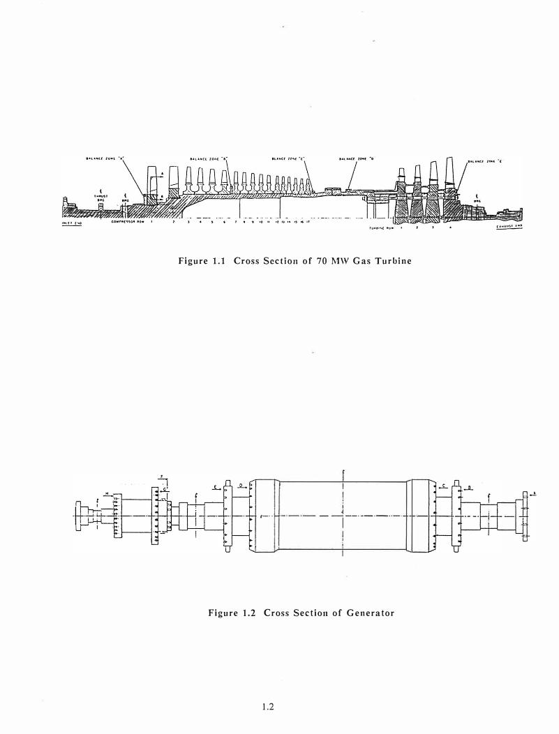
Figure 1.1 Cross Section of 70 MW Gas Turbine
,-·· - 1--·--·-··--
Figure 1.2 Cross Section of Generator
1.2
In the first case study, balance weights only were applied at the 1st compressor and
gas turbine stages. In field balancing, the 2nd balance plane is never used. Analysis and
field experience has shown that the center balance planes 3 and 4 are most useful for controlling the gas turbine 1st critical speed around 1,000 RPM. These planes should be used
first, before final balancing using planes 1 and 5 at 3,600 RPM. However, in the first case
study, the center balance planes were not available due to piping constraints.
A typical balance weight is approximately 9 - 10 oz. These balance weights are threaded screws and may be inserted into the compressor and turbine end balancing
planes by means of a long rod. In the normal multi-plane balancing procedure using influence coefficients, the trial weights are removed after the trial runs. The final
balancing calculation is performed and the balance weights are applied. This ideal
procedure is not followed when field balancing 70 MW gas turbine-generators. It is the practice never to remove a trial or initial weight if the rotor amplitude reduces. The hot end of the gas turbine is particularly difficult to get at in order to apply balance weights.
If one should drop a weight in the hot end of the gas turbine, then it is necessary to disassemble the gas turbine to remove it. Also one only gets one shot a day at the hot end gas turbine location.
Fig. 1.2 represents a typical generator. The generator shows 7 balance planes. In
the first case, no balancing weights were placed on the generator except at the coupling, plane A, and at the exciter end, plane H. Balancing corrections at planes D and C require degassing the genera tor.
In the balancing procedure performed, an HP 9845 desk computer was used in the first case and an HP 200 Series computer was used in the second case to perform the balancing calculations. By means of an advanced desk micro-computer, least squared
error and linear programming calculations can be performed using all 5 probes on the turbine-generator, at multiple speeds and power levels. In this way, an optimized balance
condition can be computed. The desktop computers were also used to collect the rotor data and to plot polar and Bode diagrams of amplitude and phase. The computer can also be used to predict the new rotor response after application of balance corrections.
In the second balancing case, a successful one-shot balancing of the compressor cold end was performed by using previously obtained balancing data on a similar machine. The one-shot balancing process is based on using the generated influence coef
ficients of the machine (or a similar machine) along with the current vibration levels.
This calculation can only be performed with a modern high-speed computer. The bal
ancing shot was of sufficient accuracy that no other corrections needed to be applied at
the compressor station. The authors firmly believe that the use of small high-speed desk computers, such as the HEWLETT PACKARD 200 Series, may have a major impact on balancing of large rotating utility equipment.
In addition to describing the balance procedure and the balancing calculations performed, additional information on the experimental characteristics of a 70 MW turbine
generator are presented. The W501 turbine-generator is a difficult unit to balance
because of the high sensitivity of both the gas turbine and exciter end of the generator.
The turbine-generator, at running speed, may be operating close to one or more resonance
frequencies. Because of this operation at or near a resonant frequency, the turbinegenerator is very sensitive to thermal bowing. Extreme care must be taken in the balancing procedure so as not to mix balancing data taken at different power levels. Presented in this paper are some of the response coefficients obtained for correction weights at various planes. It is of particular importance to note that small deviations of weight at the exciter end can cause non-linear changes in the exciter end influence coefficients. This makes the exciter end particularly sensitive to balancing.
1.3

II. INSTRUMENTATION
The following is a brief description of the instrumentation and computer equip
ment used to perform the balancing on the 70 MW turbine-generators. The most essential
element for analyzing a 70 MW turbine-generator is instrumentation to measure the
vibration amplitude and phase at various planes. Without adequate instrumentation for
vibration measurement, accurate balancing is impossible. There are various types of
instrumentation used for monitoring turbine-generator vibrations. The instrumentation
has either been shaft-rider probes or the BENTLY NEVADA dual probes which measure casing and rotor motion. Fig 2.1 represents a schematic diagram of the 70 MW turbine
generator with 5 probe locations at each bearing. The shaft-rider technique is the method
normally used by the OEM field engineer to perform balancing. In this procedure, the
field engineer physically applies a shaft-rider stick to the shaft to measure amplitude and
phase. Normally, phase is obtained from a phase generator attached to the turbine end.
In both case studies the 70 MW turbine-generators were equipped with the BENTLY
NEVADA 7000 SERIES dual probes system as shown in Fig 2.1 (with one dual probe mounted
vertically on each of the 5 bearings). The BENTLY dual probe system uses a proximity pro be for shaft relative motion and a velocity pro be for casing relative motion. An
additional probe located at either the coupling (case 1) or the exciter end (case 2)
provided the phase reference mark. The system has the capability of showing relative
shaft-to-casing motion, casing motion, or the total amplitude of motion by integrating the
casing velocity signal and vectorially adding it to the relative shaft motion. Extensive
shaft rider data was obtained on the first unit. A comparison of the shaft rider data to
the BENTLY displacement data showed considerably different amplitude and phase data.
However, balance calculations using shaft rider data or BENTLY displacement probe data
predicted similar balancing values. The non-contact BENTLY probes are preferable to the
shaft-rider stick method as the BENTLY probes are able to accurately measure a slow roll
vector. The balancing calculations should be based upon the compensated displacement
data with slow roll vibration subtracted. This is not possible with the shaft-rider sticks
because of the frequency response of the device at low speeds.
A BENTLY DIGITAL VECTOR FILTER II was used to determine synchronous amplitude and phase. In addition to determining synchronous motion, the DIGITAL VECTOR FILTER
can determine the subsynchronous and total vibration levels. If there is a large
discrepancy between the total motion and the synchronous motion, then other effects may
be present in the system such as rotor instability, misalignment, or shaft rubs. A tape recorder was used to store the balancing data from 5 probes in the first case for future analysis. In the second case, when the balancing was performed, an operational tape
recorder was not available. This, however, was not a serious restriction to accomplishing
the balancing procedure.
An HP 9845B and 9816 computer with an HP 2671G printer were used in the two
cases to run the least squared error constrained optimization balancing program and the
BENTLY ADRE software program for the collection and analysis of the experimental data.
A 2-pen analog plotter was also used to plot polar diagrams at the various stations. In order to perform the least squared error balancing procedure using 5 BENTLY probes, the
computer is essential for carrying out the computations. A HEWLETT PACKARD 3582
SPECTRUM ANALYZER was also used to examine the vibration spectrum.
2.1
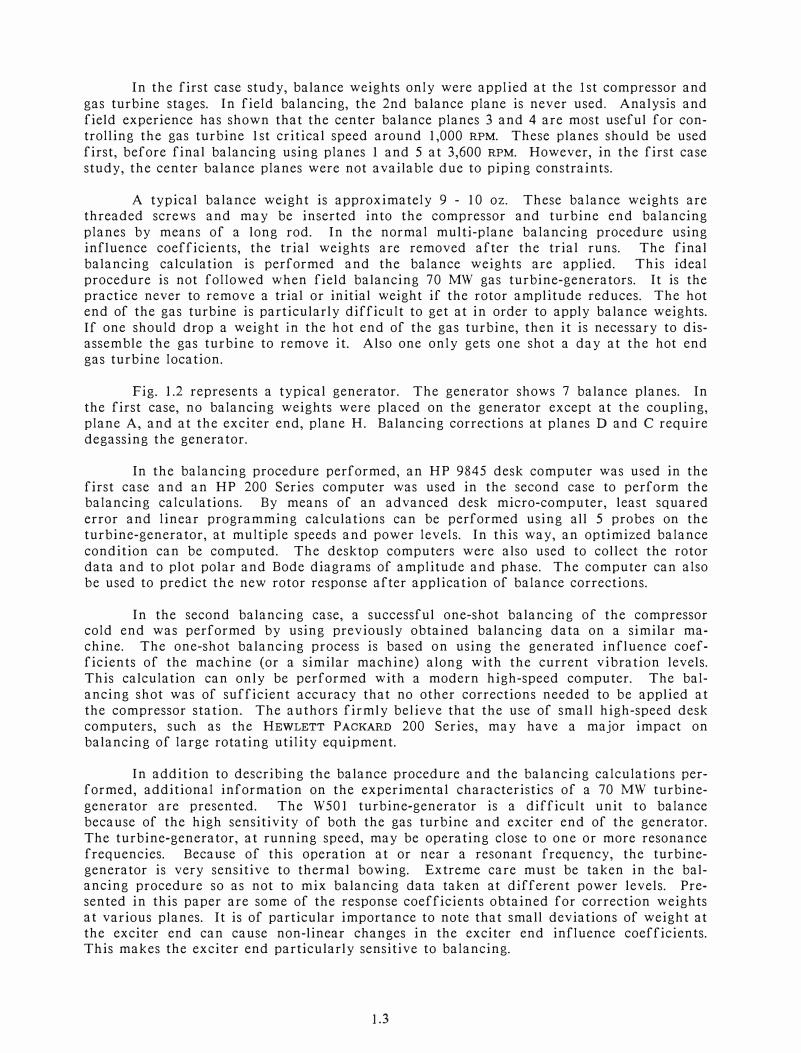
In the first case, the synchronous vibration amplitude and phase data was obtained for various speeds and probe locations by means of the field portable TURBOBALANCER developed by E. Shepherd of MECHINTEL, INC. This device allows one to obtain print-outs of up to 6 probes recording the RPM, amplitude and phase on a thermal printer. Data was
recorded at the 5 probes at various speeds on spin up and coast down as well as at 3,600 RPM under various power levels. The thermal print-out obtained from the TURBOBALANCER
was found to be exceptionally useful in recording the vibration data on start up and coast down. This data allowed the authors to compute the optimum balance correction using
vibration data at several critical speeds as well as at running speed under O and full power levels. In the second case, the BENTLY ADRE program was used to record two probes and the additional data of the other probes was recorded by hand.
TE
A
GAS TUROINE
,. Vert
CE GENERATOR
0 c
Transducer orientation and direction of
00 rotation viewed from turbine.
Looking toward generator
Note: The code TE refers to Turbine End. The code CE refers to Compressor End.
1 D E
Figure 2.1 Schematic Diagram of Probe Locations for 70 MW Turbine Generator
2.2

III. CRITICAL SPEEDS of 70 MW TURBINE-GENERATOR
3.1 Gas Turbine Critical Speeds
In order to understand the planes at which balance weights will be most effective,
It IS useful to have a critical speed analysis of the gas turbine-generator systems. In the
first series of critical speed analyses, the gas turbine was analyzed by itself. A model of
the 70 MW gas turbine was developed from a scaled drawing.
Fig 3.1 represents the cross-section of the 54-station gas turbine rotor. The
bearings supporting the gas turbine are 4 pad tilting-pad bearings with load between pads.
Fig 3.2 represents the first 3 modes of the gas turbine. Fig 3.3 represents the animated 1st
critical speed mode shape for the 70 MW gas turbine. From an observation of the rotor mode shape, it is apparent that the center rotor balance planes 3 and 4 will be the most
effective for balancing the rotor I st critical speed. Note that the coupling at station I
will have very little influence on the first mode.
Static coupling shots are often applied on the gas turbine first compressor and gas
turbine stages, at balance planes I and 5. In a static balancing shot or correction, two
weigh ts are inserted at the two balance planes in phase. This combination of weigh ts has
a strong influence on the response characteristics of the gas turbine at the turbine 1st
critical speed. If this combination is used to trim balance the turbine at 3,600 RPM, then
high excitation or even bowing of the turbine may occur at the 1st critical speed.
Therefore, it is preferable to first balance the gas turbine around 1,000 RPM with a center
plane correction or with a static correction at the end planes before attempting to trim
balance at 3,600 RPM.
Fig 3.4 represents the gas turbine animated second mode. With the assumed bear
ing stiffness values of 4E6 Lb/in, the rotor second critical speed occurs at 2,793 RPM. In this mode, the turbine and compressor ends are 180
° out of phase. If a balance correction
is placed at the center plane, it will have no effect on the response of the rotor at the
second critical speed. In this case, the balance correction is said to be orthogonal to the
second mode.
A single plane balancing correction at either the compressor or turbine end will
affect the first mode as well as the second mode. A dynamic balancing shot, in which
weights are placed 180°
out of phase at the compressor and gas turbine ends, would have
little effect on excitation of the first gas turbine mode. Under the circumstances, this
weight distribution would be orthogonal to the first mode and hence would not re-excite
the first critical speed. This weight combination was not employed by the OEM field
engineer for trim balancing at running speed for unit #1.
3.2 Influence of Bolted Section on Gas Turbine Critical Speeds
After extensive experimental data was obtained on the first gas turbine unit, it
appeared that the hot end of the turbine was starting to enter a third critical speed. The gas turbine critical speed study showed that the third turbine bending mode should be
above 5,400 RPM. However, the analysis also indicated that over 80% of the strain energy of the rotor is concentrated in the area of the bolted-up flange section connecting the
axial compressor to the gas turbine. Over an extended operating period, the center span
3.1

CRITICAL SPEED ANALYSIS OF 70 HH POHER STATION GAS TURBINE ON 4 TILT-PAD BRGS,3,600 RPH DESIGN
I' I ..a : ..J im I a, : C!l
ru1 i :m
. Ill 'I C!l 0 Ill 01 • z ..., Z1 ...-
I
� I
�: I 1%1 :I! 1%11 :I!
- ROTOR CROSS SECTION -Ht• 72807.! Lb Lt• 389.3 In.
RY.IAL
COMPWESSOR GAS
TURHirlE
NO. OF STATIONS - 54
NO. OF BEARINGS (�SEALS) - 3
(T) mm . m
0 . z ....
� I
1%1 :I!
Figure 3.1 Cross-Section of 54 Station 70 MW Gas Turbine
CRITICAL SPEED ANALYSIS OF 70 MH POWER STATION GAS TURBINE ON 4 TILT-PAD BRGS,3,600 RPM DESIGN
UNDAMPED SYNCHRONOUS SHR�TMODES Ht• 72S�7.S Lb Lt• 389.3 In.
3 ( 4!581 RPM)
2 C 2793 RPM) 1 C 1171 "'911) ------------.. .........
..................
NO. O� STATIONS - �4
NO. O� BEARINGS C�9tALS) • 3
" "
Figure 3.2 Modes of 70 MW Gas Turbine With Symmetric Tilting 4-Pad Bearings
3.2

CRITICAL SPEED ANALYSIS OF 70 MH POHER STATION GAS TURBINE ON 4 TILT-PAD BRGS,3,600 RPM DESIGN
UNDAMPED SYNCHRONOUS SHArTMODES
Wt- 72607.S Lb Lt• 389.3 In.
Figure 3.3 Animated 1st Critical Speed Mode of 70 MW Gas Turbine
CRITICAL SPEED ANALYSIS OF" 70 MH POHER STATION GAS TURBINE ON 4 TILT-PAD BRGS,3,600 RPM DESIGN
(SJ 0 (SJ z tn
\!) I Cl'. co �
UNDAMPED SYNCHRONOUS SHArTMOD£S
Wt- 72807.S Lb Lt- 389.3 In.
HZ C 2793 RPH>
-------·
NO. OF STATIONS a 54
NO. OF BEARINGS (&SEALS) • 3
Figure 3.4 Animated 2nd Critical Speed Mode of 70 MW Gas Turbine
3.3
bolts will have a tendency to creep. This creep effect is enhanced if the rotor has high
unbalance causing bowing in the first mode. The creeping causes a moment release at the
bolted-up section.
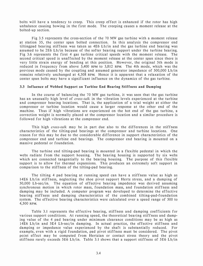
Fig 3.5 represents the cross-section of the 70 MW gas turbine with a moment release
at station 35, the center span bolted connection. In this analysis the compressor end tiltingpad bearing stiffness was taken as 4E6 Lb/in and the gas turbine end bearing was
assumed to be 2E6 Lb/in because of the softer bearing support under the turbine bearing.
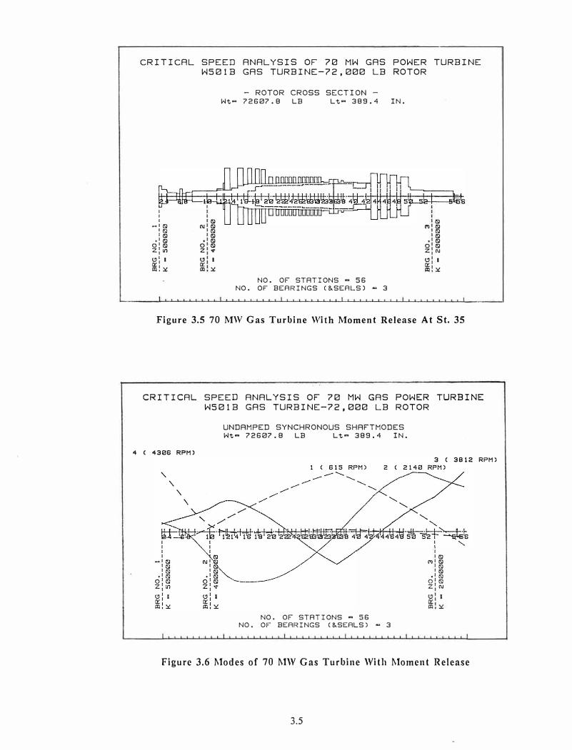
Fig 3.6 represents the first 4 gas turbine critical speeds with the moment release. The
second critical speed is unaffected by the moment release at the center span since there is
very little strain energy of bending at this position. However, the original 5th mode is
reduced in frequency from above 5,400 RPM to 3,812 RPM. The 4th mode, which was the
previous mode caused by the coupling and assumed generator impedance of 500,000 Lb/in
remains relatively unchanged at 4,308 RPM. Hence it is apparent that a relaxation of the
center span bolts may have a significant influence on the dynamics of the gas turbine.
3.3 Influence of Webbed Support on Turbine End Bearing Stiffness and Damping
In the course of balancing the 70 MW gas turbine, it was seen that the gas turbine
has an unusually high level of cross-talk in the vibration levels experienced at the turbine and compressor bearing locations. That is, the application of a trial weight at either the
compressor or turbine location would cause a larger response at the other end of the
machine. Thus if high vibrations are experienced on the hot end of the gas turbine, a
correction weight is normally placed at the compressor location and a similar procedure is
followed for high vibrations at the compressor end.
This high cross-talk may be in part due also to the differences in the stiffness
characteristics of the tilting-pad bearings at the compressor and turbine locations. One
reason for this may be due to the considerable difference in support characteristics of the
compressor end and turbine end bearings. The compressor end bearing is mounted on a
massive pedestal or foundation.
The turbine end tilting-pad bearing is mounted in a flexible pedestal in which the
webs radiate from the support housing. The bearing housing is supported by six webs
which are connected tangentially to the bearing housing. The purpose of this flexible
support is to allow for thermal expansions. This produces an extremely soft support in comparison to the stiffness of the tilting-pad bearing.
The tilting 4 pad bearing at running speed can have a stiffness value as high as
14E6 Lb/in stiffness, neglecting the shoe pivot support Hertz stress, and a damping of
50,000 Lb-sec/in. The equation of effective bearing impedence was derived assuming
synchronous motion in which rotor mass, foundation mass, and foundation stiffness and
damping may be included. A computer program was developed to determine the effective
bearing stiffness and damping characteristics of the combined tilting-pad-foundation system. The effective bearing characteristics were calculated over a speed range of 500 to
4,500 RPM.
Table 3.1 represents the effective bearing, stiffness and damping coefficients for
various support conditions. At running speed, the theoretical bearing stiffness and damp
ing value of the 4 pad bearing under minimum clearance conditions may be as high as
14E6 Lb/in and 5E4 Lb-sec/in damping. In actual practice, the effective stiffness and
damping or impedance value experienced by the shaft is substantially reduced. For example, even with a rigid foundation, pad pivot stiffness must be considered. The pivot
point effect may be computed from Hertzian or contact stress theory and the pivot stiffness rarely exceeds 5E6 Lb/in. Table 3.1 shows that a support stiffness of 5E6 Lb/in
3.4
CRITICAL SPEED ANALYSIS OF 70 MW GAS POWER TURBINE W501B GAS TURBINE-72,000 LB ROTOR
l I l
-•(S) l (S) l (S)
·' (S) o' (S) z: Lt')
l? l I ci:' IIll�
(S) N (S)
(S) (S) (S)
0 (S) z ....
l? I Cl: IIl �
- ROTOR CROSS SECTION -
Wt= 72607.8 LB Lt= 389.4 IN.
NO. OF STATIONS = 56
NO. OF BEARINGS (&SEALS) - 3
(S) (') (S)
(S) (S) (S)
0 (S) Z N
l? I Cl: IIl �
Figure 3.5 70 MW Gas Turbine With Moment Release At St. 35
CRITICAL SPEED ANALYSIS OF 70 MW GAS POWER TURBINE W501B GAS TURBINE-72,000 LB ROTOR
UNDAMPED SYNCHRONOUS SHAFTMODES
Wt= 72607.8 LB Lt = 389.4 IN.
4 C 4306 RPM)
NO. OF STATIONS = 56
NO. OF BEARINGS (&SEALS) - 3
(S) (') (S)
(S) (S) (S)
0 (S) Z N
Figure 3.6 Modes of 70 MW Gas Turbine With Moment Release
3.5
RPM)

TABLE 3.1
INFLUENCE OF GAS TURBINE - BEARING SUPPORT HOUSING ON EFFECTIVE BEARING COEFFICIENTS
[N = 3,600 RPM, Kb
= 14 x 106 Lb/in, Cb
= 5 x 10⁴
lb-sec/in]
Kr (Lb/in) wr (lb)
0
200,000 (Ce) 3.58
(Ke) .198E6
500,000 22.07
.493E6
1E6 86.10
.973E6
2E6 327
l.894E6
5E6 1,744.9
4.336E6
Kr= foundation stiffness (Lb/in)K
b = bearing stiffness (Lb/in)
Ke
= effective bearing stiffness
wr (lb) wr (lb)
50 100
2.96 2.4
.180E6 .162E6
20.53 19.01
.475E6 .457E6
83.10 80.09
.956E6 .939E6
321 316
1.878E6 1.862E6
1,733.9 1,722.8
4.323E6 4.309E6
Wf
= foundation weight (lb)C
b = bearing damper (lb-sec/in)
C = effective bearing damping e
3.6
wr (lb)
250
1.05
.107E6
14.79
.403E6
71.38
.886E6
299
l.813E6
1,689.7
4.269E6

will reduce the bearing stiffness from 14E6 to 4.3E6 Lb/in. A dramatic reduction of
bearing damping is experienced by foundation flexibility. The bearing damping at the
compressor end is reduced from 50,000 Lb-sec/in to 1,734 Lb-sec/in. At the turbine end, the flexible pedestal may have a support stiffness well below IE6 Lb/in. In this case, the
effective damping at the gas turbine location will reduce from 50,000 Lb-sec/in to below
80 Lb-sec/in. The flexible web required for thermal expansion at the turbine end
bearing, in essence, kills the high damping of the tilting-pad bearing. This effect adds to the sensitivity of the gas turbine to unbalance and attributes to its high cross-talk. Such dissimilar pedestal effects are not normally experienced with steam turbines.
3.4 Critical Speeds of 70 MW Turbine-Generator System
Discussed in this section are the types of critical speeds that may be expected with
a 70 MW turbine-generator. In the original analysis of the gas turbine, in order to simulate the effect of the generator, a simple spring rate of 500,000 Lb/in was assumed at
the coupling end. It is the assumption of the coupling impedance that governs the value of the turbine 3rd critical speed with high coupling end motion. However, in order to
more fully understand the dynamics of the entire turbine-generator set, the generator was included with the 70 MW turbine to form an 86-station model. Table 3.2 represents the bearing types and dimensions used in the 70 MW turbine-generator set.
A critical speed analysis of the gas turbine rigidly coupled to a typical 70 MW
generator was run. In this unit, the exact configuration of the generator and its bearings
were not known. In the evaluation of the experimental data for the 70 MW turbine
generator for unit #2, it appeared that the exciter may be operating through several critical speeds. It appeared that at 3,600 RPM the exciter was operating at or near a
critical speed on the second unit that was field balanced.
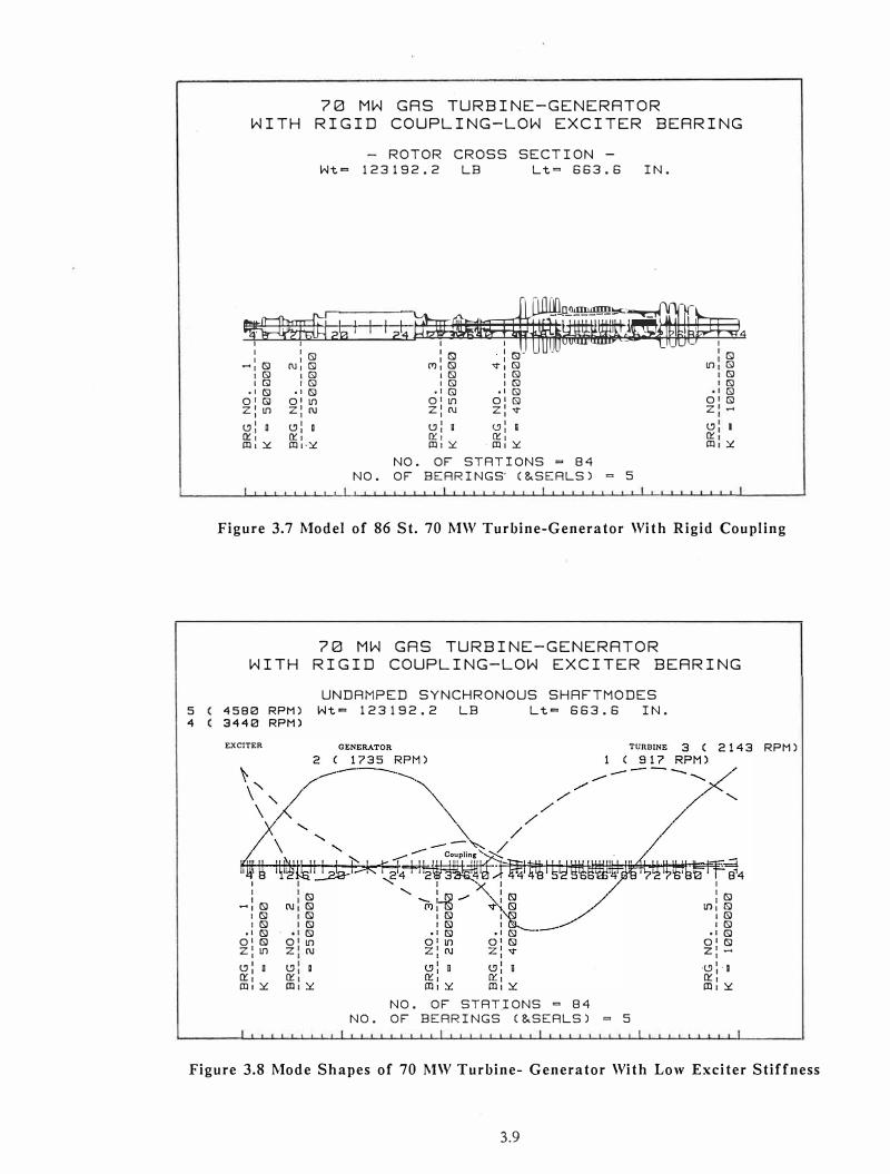
Fig 3.7 represents a cross-section of the 84-station model used. The total weight for the system is estimated to be approximately 123,200 Lb. It would be highly desirable
to obtain an exact cross-sectional drawing of the generator and its bearings in order to
develop a more accurate model for the turbine-generator system. However, the
characteristics developed for this system are very similar to previously observed critical
speeds for this class of machinery.
Fig 3.8 represents a summary of the modeshapes determined for the 70 MW turbine-generator. There are 5 modes calculated with the assumed bearing stiffness
values. The first mode at 917 RPM is the first critical speed of the turbine. The second mode at 1,735 RPM is the first critical speed of the generator. The third mode at 2,143 RPM is the second mode of the turbine. The fourth mode at 3,440 RPM is the second mode
of the generator. The fifth system mode at 4,580 RPM is the third mode of the generator. In this model a low stiffness of 500,000 Lb/in was assumed for the exciter end bearing. It
is of interest to note that both modes 4 and 5 show high exciter amplitude. If the exciter spring rate is reduced below 500,000 Lb/in, then the fifth mode will reduce from 4,500
RPM to the 3,600 RPM speed range. Therefore, the dynamic characteristics of the generator modes are highly dependent on the exciter end bearing stiffness values. Details of these modes will be described in the following sections.
Fig 3.9 represents the first mode of the gas turbine. In this analysis, the hot end
of the gas turbine was assumed to have a relatively low bearing stiffness value of 1,000,000 Lb/in. The reason for this reduced bearing stiffness at the gas turbine end is
the flexible webbed bearing cartridge supporting the tilting-pad bearing at the hot end. This mode should be expected to occur between 900 and 1,100 RPM. An analysis of the strain energy of the system shows that 55% is energy associated with the hot end gas tur-
3.7

TABLE 3.2
TURBINE - GENERA TOR SYSTEM BEARINGS
[Gulfcrest 32 Turbine Oil.. .... (-1.2u Reyns)]
Location Type L/D L D Cd
CiD w Descrip-No. (dim) (in) (in) (in) (mil/in) (lb) tion
1 (E) Axial-Groove 1 to .75 -5.78 5.78 .010 5.88 2,200 Exciter Partial Arc
2 (D) Relieved .78 8.2 * 10.5 *
.024 2.29 23,000 Generator Axial-Groove (OB) ( 160° arc brg) Outboard
3 (C) Relieved .78 8.2 * 10.5 * .023 2.29 23,000 Generator Axial-Groove (IB)
( 160° arc brg) Inboard
4 (B) Tilting-Pad .82 11.5* 14.o* .032 1.14 36,000 Compressor 4-Pad (pad Cl) (CE) 0.5 PreloadLoad Between .020 Pads (brg Cl)
5 (A) Tilting-Pad .82 11.5 * 14.o* .032 1.14 36,000 Turbine 4-Pad (pad Cl) (TE) 0.5 PreloadLoad Between .020 Pads (brg Cl)
* Scaled from photographs
3.8
70 MH GAS TURBINE-GENERATOR
HITH RIGID COUPLING-LOH EXCITER BEARING
ROTOR CROSS SECTION -
Wt= 123192.2 LB Lt= 663.6 IN.
�w.J-<-G101 _'-.J_JI 2� ��4
1 1 1��
: : CS) : CS) • : CS) CS) - 1 (S) C\J I CS) C"J 1 (S) '<t 1 CS) in CS)
1 CS) 1 CS) 1 (SJ 1 CS) (S) 1Gl 1G) IG) 1 (S) (S)
• I (S) ol (S) • 1 GJ • 1 G) (S) 01GJ 01in 01in o1Gl o Gl z: in z: (\J z: (\J z: '<t z
t, 1 D t, 1 a t'.1 1 a t'.1 1 B t, I Cl'.'.: Cl'.'.: Q'.: Q'.: Cl'.'. m1:::.:: m1-:::.:: m1:::.:: · m1:::.:: m :::.::
NO. OF STATIONS = 84
NO. OF BEARINGS (&SEALS) = 5
Figure 3.7 Model of 86 St. 70 MW Turbine-Generator With Rigid Coupling
70 MH GAS TURBINE-GENERATOR
HITH RIGID COUPLING-LOH EXCITER BEARING
UNDAMPED SYNCHRONOUS SHRFTMODES
5 4580 RPM) Wt= 123192.2 LB Lt= 663.6 IN.
4 3440 RPM)
EXCITER
1 1
-: (S) 1 (SJ 1 (S)
,1 (S) o1 ISl z: int, 1 D Cl'.'.: m1:::.::
(S) (\J (S)
(SJ (S) (S)
O in z (\J
t:J a Cl'.'. Cil :::.::
NO. OF STATIONS = 84
NO. OF BEARINGS C&SEALS) = 5
I
: (S) in 1 (SJ
I (S) I (S)
• I GJ QI (SJ z'-' ·t'.J I. I Cl'.'.: m,:::.::
RPM)
Figure 3.8 Mode Shapes of 70 MW Turbine- Generator With Low Exciter Stiffness
3.9

70 MW GAS TURBINE-GENERATOR
WITH RIGID COUPLING-LOW EXCITER BEARING
UNDAMPED SYNCHRONOUS SHAFTMODES
�t= 123192.2 LB Lt = 663.6 IN.
MODE 1 FREQUENCY - 15 HZ ( 917 RPM)
������ -----------
���� /��--------- -,,,
�<::::;
·�;,,,��-------------���-:; :�-�--:-------------------�
�H-!lttH-++++����0 �M��J-�m-��B.4 1'' .... ....., I I �', -,__ I IS)•
st I IS) '>,', -- - _ILJ1'"(Sf J CS) ,,, '''
-------- ---- I (SJ • I IS) ', ', 1,..tl(
.1 IS) ', ---- ---"'.f.B' o• IS3 -- --------- >
Z: '1'" '---------- I
t'.J I D t'.J :. I Q'.: n'.1 m,Y m,Y
NO. OF STATIONS = 84
NO. OF BEARINGS (&SEALS) 5
Figure 3.9 Animated 1st Turbine Mode of 70 MW Turbine-Generator
70 MW GAS TURBINE-GENERATOR
WITH RIGID COUPLING-LOW EXCITER BEARING
UNDAMPED SYNCHRONOUS SHAFTMODES
�t= 123192.2 LB Lt = 663.6 IN.
MODE 2 FREQUENCY - 29 HZ ( 1735 RPM)
------
NO. OF STATIONS = 84
NO. OF BEARINGS C&SEALS) = 5
'0 I 84
: IS) lfl1 IS)
I IS) I IS)
.1 IS) QI IS) z:-
t'.J' i Q'.: m,y
Figure 3.10 Animated 1st Generator Mode of 70 MW Turbine-Generator
3.10

bine bearing and 35% is strain energy of bending. Therefore, the hot end turbine bearing
stiffness will have a predominant effect on controlling the gas turbine first critical speed.
Fig 3.10 represents the first mode of the generator at 1,735 RPM. Note that in this
figure, the exciter end is a node point. There is 74% of the strain energy for this mode
associated with the generator inboard and outboard bearings. Therefore, the occurrence
of the generator first mode is strongly governed by the inboard and outboard generator bearings.
Fig 3.11 represents the second critical speed of the gas turbine. Note that the
center plane of the gas turbine is a node point. Therefore, the center plane is very effective in balancing out the gas turbine first mode, but will not influence the turbine
second critical speed. If high vibrations occur around 1,000 RPM on the gas turbine, then
the gas turbine center plane will be very effective in balancing out this mode without substantially influencing the gas turbine second critical speed. The strain energy distri
bution for the gas turbine second critical speed at 2,143 RPM has 61 % of the strain energy associated with the gas turbine bearings. Hence, the gas turbine 2nd mode is controlled
only by the two tilting-pad bearings of the gas turbine.
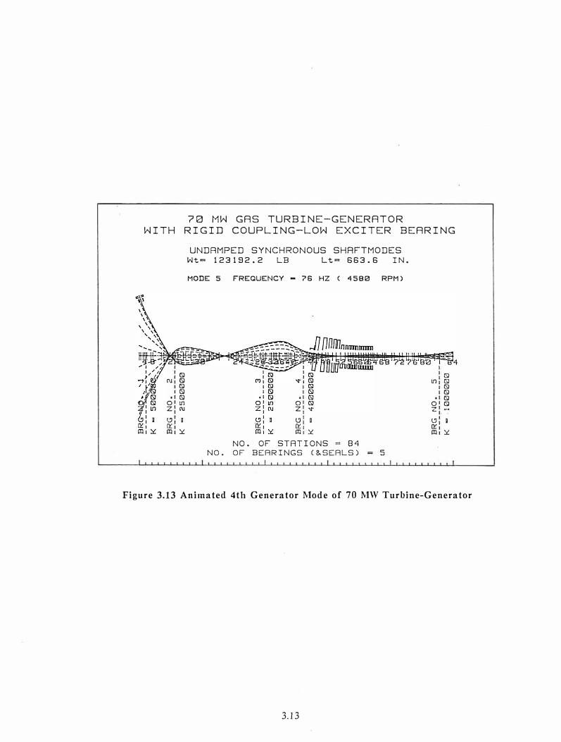
Fig 3.12 and Fig 3.13 represent the system 4th and 5th critical speeds. These critical speeds are of particular importance since they occur near the opera ting speed
range. Of major concern, is the 5th mode at 4,500 RPM. If the exciter end bearing stiffness is actually lower than 500,000 Lb/in, then there will be three generator critical speeds. In both of these critical speed modeshapes, the maximum amplitude occurs at the
exciter end. This modeshape is controlled predominantly by the inboard and outboard generator bearings and somewhat by the exciter end bearing. The exciter end bearing has
33% of the strain energy. For the third generator critical speed or the fifth system critical speed at 4,500 RPM, a reduction in the exciter end bearing stiffness will cause the
third generator critical speed to reduce to the operating speed range of 3,600 RPM. Table 3.3 represents a summary of the 5 critical speeds of the 70 MW turbine-generator.
Analysis of the experimental data of the exciter end polar plots and also of the high magnitude of the exciter influence coefficients for unit #2 indicated that the exciter was operating near a critical speed. It is possible that the exciter is operating at its third critical speed. This made the problem of balancing the unit #2 70 MW turbine-generator extremely difficult because of the high sensitivity and nonlinearity of the exciter end. It
may be possible to reduce the sensitivity of the exciter end by a redesign of the bearing support at the exciter location. The current unit #2 exciter had an unacceptably high influence coefficient at running speed. These influence coefficients will be described in
detail in the later sections.
In unit #l, one of the difficulties experienced in balancing the gas turbine end appeared to be due to the operation near a third turbine critical speed. This behavior was
not experienced on the second unit.
3.11

70 MW GAS TURBINE-GENERATOR
WITH RIGID COUPLING-LOW EXCITER BEARING
I I
: : lSl -1 lSl N1 lSl
I ts) I ts) I ts) I ts)
.1 ts) .1 (S) QI (S) QI lfl z: lfl z: N
CJ 1 D l'1
1 Q'.: Q'.: m1::.: m1::.:
UNDAMPED SYNCHRONOUS SHAFTMODES
Wt= 123192.2 LE Lt = 663.6 IN.
MODE 3 FREQUENCY • 36 HZ ( 2143 RPM)
I
: lSl CTJ1 (S)
I (S) I lSl
.1 ts) QI lfl z:ru
t,: D
Cl'.1 m1::.:
NO. OF STATIONS = 84
NO. OF BEARINGS (&SEALS) 5
Figure 3.11 Animated 2nd Turbine Mode of 70 MW Turbine-Generator
70 MW GAS TURBINE-GENERATOR
WITH RIGID COUPLING-LOW EXCITER BEARING
UNDAMPED SYNCHRONOUS SHAFTMODES
Wt= 123192.2 LE Lt= 663.6 IN.
MODE 4 FREQUENCY • 57 HZ ( 3440 RPM)
CTJ1 I ts) I (S)
.1 (S) QI l[) z:ru
(.'.} I
Q Cl'.: mi::.:
0 z
t'.J D Q'. m ::.:
NO. OF STATIONS = 84
NO. OF BEARINGS (&SEALS) = 5
S-4I
: (S) lfl1 (S)
I (S) I (S)
.1 (S) QI (S) z 1 -.1
(.'.JI
I Cl'.: mi::.:
Figure 3.12 Animated 3rd Generator Mode of 70 MW Turbine-Generator
3.12
70 MW GAS TURBINE-GENERATOR
WITH RIGID COUPLING-LOW EXCITER BEARING
(SJ (\J (SJ
(SJ (SJ (SJ
O lf1 z (\J
t:J D 0:: m �
UNDAMPED SYNCHRONOUS SHRFTMODES
Wt= 123192.2 LB Lt= 663.6 IN.
MODE 5 FREQUENCY - 76 HZ ( 4580 RPM)
0 z
t:J D 0:: m �
NO. OF STATIONS = 8�
NO. OF BEARINGS (&SEALS) 5
CS) lf1 CS)
(SJ (SJ (SJ
O CS) z -
t:J g 0:: m �
Figure 3.13 Animated 4th Generator Mode of 70 MW Turbine-Generator
3.13

IV. SAMPLE EXPERIMENTAL DATA on TYPICAL 70 MW TURBINE-GENERATOR
4.1 Gas Turbine Vibration - Turbine Bearing
This section describes typical experimental vibration data obtained from a 70 MW W501 gas turbine-generator. Fig 4.1 represents the total vertical motion at the hot end of the gas turbine with 38.9 oz applied at the compressor location. The dotted line in the figure represents the absolute motion and the solid line represents the amplitude corrected for the slow roll vector.
The turbine and generator first critical speeds are around 1,100 and 1,400 RPM in this system. A second critical speed is observed at 2,000 RPM. This is a rotor casing mode. The second turbine critical speed is approximately 2,800 RPM. At the hot end of the gas turbine, the amplitude is extremely large at 3,600 RPM. The gas turbine appears to be operating near a critical speed. In this system (unit #l), it was believed that the turbine is operating near its third critical speed due to the lack tightness at the center span bolted connection. The hot end of this particular gas turbine was extremely difficult to balance because of operation in the vicinity of a critical speed.
Fig 4.2 represents the polar diagram of the hot end of the gas turbine. This particular polar diagram was generated using the BENTLY ADRE system in conjunction
with a HEWLETT PACKARD computer. From the observation of the peak amplitudes on the polar diagram and from the rate of change of phase angle, one can estimate the location of the various critical speeds. It is apparent, for example, that the gas turbine first critical speed is at 1,100 RPM. As the machine speed is increased from 3,000 to 3,600 RPM,
there is a large phase change of approximately 120°. This is an indication that the hot end of the gas turbine is approaching its third critical speed. The turbine end influence coefficients, therefore, will be sensitive to various such effects as thermal bow, unbalance, and power level.
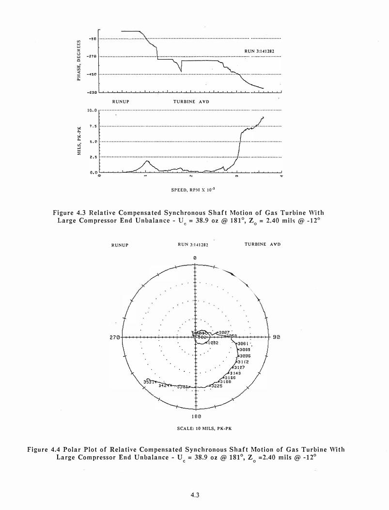
Fig 4.3 represents the relative motion at the hot end of the gas turbine with the run-out vector subtracted from the vibration data. The diff erencc in amplitude between Figs 4.3 and 4.1 represents the casing vibration. In Fig 4.3, the first turbine critical speed is clearly indicated at 1,100 RPM. The gas turbine second critical speed appears to be at 3,000 RPM. However, it is seen that instead of the amplitude decreasing above 3,200 RPM,
the amplitude continues to increase. Fig 4.4 represents the polar diagram for the relative rotor casing amplitude at the gas turbine location. The large phase angle change of approximately 120° observed for a speed change of 3,000 to 3,600 RPM is an indication of the gas turbine approaching a third critical speed. This rapid phase angle change near the running speed made it extremely difficult to balance the hot end of the gas turbine. There was also observed a considerable difference in amplitude and phase at 3,600 RPM
when the power level was increased to 70 MW. In order to successfully balance this machine, the least squared error constrained linear program was employed with data measurements taken at 10 MW and at the full power level of 70 MW.
4.2 Gas Turbine Vibration - Compressor Bearing
Fig 4.5 represents the absolute motion at the compressor end of the gas turbine with 39 oz applied at the compressor location. The application of the large correction weight at the compressor end of the gas turbine causes an excitation of the gas turbine second critical speed at 2,700 RPM. Above 2,700 RPM, the amplitude reduces at the compressor end, whereas the amplitude increases at the hot end of the gas turbine. The
4.1

···· ··· ······ ........................... ·············································································-·······
'
RUN 3:141282
(.'.) -271io "' ....... Solid: Comp AV Dashed: Un.comp AV
·· ...<C -�50
· ···· ... ···························
RUNUP TURBINE AV
10.0 ···········································-·····································································
7.5
5."
···-····································-············································ ....... ·····-.-.. �············
............. "''."��:·�''"; :\;j''�\.";:/>-: '.\, .. ,,:: ............. . ·-· '
z. s ............. ;�·: ........... , .... ,c. •••• • • ••••••
1 ... •• ...... COMPENSATED
0,oc_..��_,_-==......._�..._.��__,_���...___.�� ....... ���-'-'�--......... ��---"-' "'
SPEED, RPM X 10·3
Figure 4.1 Absolute Synchronous Gas Turbine Motion With and Without Compensation With Large Compressor End Unbalance - U = 38.9 oz @ 181°
, Z = 2.70 mils @ -5°
C O
RUNUP RUN 3:1�1282 TURBINE AV
0
180
SCALE: 10 MILS, PK-PK
Figure 4.2 Polar Plot of Compensated Absolute Gas Turbine Motion With Large Compressor End Unbalance - U = 38.9 oz @ 181 °, Z = 2.70 mils @ -5°
C O
4.2
VJ "'"'-�l:l •••.•••••••.••••••..•••••••. ·•••·•••·•••••••••••••·••••••••••••·••••·••••••·•••••••••·••••• •••••••••••·•••••••
:>: RUN 3:141282
� -27" Q
� -�Se ····················································································· ··························
RUNUP TURBINE AVD
ICJ.0 ··••·••••··••·•·•••··•·······•·•••···••·••·•·••••·•••·•···••·•·•·•·••••••••••·•••••••••·••••···•••··••··•·•···•••
7. 5 •••..••••.•.•••...•.••••.•..••.••••...•••.••..••.••••...•....•••...••••••••..•••••.••••••••...•. ·••·•·••••••··•
s.e ······················································································ ··························
SPEED, RPM X 10·3
Figure 4.3 Relative Compensated Synchronous Shaft Motion of Gas Turbine With Large Compressor End Unbalance - U = 38.9 oz @ 181 °, Z = 2.40 mils @ -12°
c O
RUNUP RUN 3:141282 TURBINE AVD
0
··.�
90
180
SCALE: 10 I\IILS, PK-PK
Figure 4.4 Polar Plot of Relative Compensated Synchronous Shaft Motion of Gas Turbine With Large Compressor End Unbalance - U = 38.9 oz @ 181°, z =2.40 mils @ -12°
C O
4.3

Cl ••••••••••••••••••••••••••••••••••••••••••••••••••••••••••••••••••••••••••••••••••••••••••••• •••••••••••••••••••
-,o
-27(;
···•··•• ., • RUN 3:141282 ..................... -.·���·::·.· .. ::·.·::/_�·::�·::·:-:-.,.: ..................................... Sol iJ: Comp··.·······
Dashed: Uncomp
•••••••••••••••••••••••••••••••••••••••••••.•••••••.••••••••••••••••••.•••••••••••••• :;:-:: ·:-.-:.-:":":-.> .. -.::···········
RU1'UP COMPRESSOR BY
7. 5 ······-·································································�..:.:.:····································
/ � COMPENSATED
5. 0
2, 5
\.rv,\� .. .. .. ·"" ···'�---- ... ,.-, .
- --,,.. ...... ,..
..._,,..4J· ................ ··,
UNCOMPENSATED ./ ' 1
··············.:::.:::i····:.·.:.
·,;:-:
::.:.:
·;:.
:, ... ,· ........ :·::· ......................................................... .
\ o.oL...��,._i.a:::.��-L"---'��1-....��.__c���-'-���-'-��--'-��...,__,
SPEED, RPM X 10·3
Figure 4.5 Absolute Compressor Synchronous Compensated and Uncompensated Motion With Large Compressor End Unbalance - U = 38.9 oz @ 181 °, Z = 2.2 mils @ -41 °
C O
...
:,::
�
" ·················································································································
_g(l
-27Cl'
RUN UP
7.5
5.0
2.5
...... , .......... ,• ••• .-' '· ·-. RUN 3:141282
............. ::::·,,,·, ......................•........... Solid: Comp .......•. · .. , Dashed: Uncomp
COMPRESSOR BYD
,. ......... ,.,_ ..... .., � \ ·· ...
...... _... ·.,
UNCOMPENSATED
·············- .. ••·•· •.•. h�/ • ..•.••. ... .,.:·· .. · ......................... ····
-··············
0.0L...��..J.-=::.=;:::;:�'.:..._��..1.__���1-...��,._J_���...1....�-�� � v
SPEED, RPM X 10·3.
Figure 4.6 Relative Compensated and Uncompensated Compressor Motion With Large Compressor End Unbalance - U = 38.9 oz @ 181 °, Z = 1.96 mils @ -50°
C O
4.4

vibration at the compressor end is well behaved in comparison with the characteristics at
the hot end. Casing effects are not as clearly evident at the compressor end of the gas
turbine.
Fig 4.6 represents the relative shaft-to-casing motion at the compressor end
location. The dotted line is the relative rotor casing motion at the compressor bearing
location. The solid line is the shaft motion with the low speed run-out subtracted. The slow roll vector is almost 2 mils. This is an indication that the rotor may have been bent
during previous balancing attempts by the OEM field engineer. By subtracting the slow
roll vector, a considerably different amplitude and phase angle pattern is observed. The
large phase change observed with the slow roll vector subtracted is an indication of the
presence of the critical speeds. There is a large phase change at 1,000 RPM and at 1,350
RPM. The phase change at 1,000 is the turbine first critical speed and the phase change at
1,350 RPM is the generator first critical speed. The gas turbine second critical speed
appears to be at 3,300 RPM when the relative shaft casing motion is examined. Note that
the compressor end motion reduced after passing through the second critical speed,
whereas the hot end of the gas turbine continues to increase. This characteristic of the
W501 gas turbine considerably complicates the balancing procedure. The rotor has its
highest sensitivity factors near running speed. It is also important to note that, if a rotor
is operating near a critical speed, then it is highly susceptible to thermal bowing.
4.3 Generator Vibration
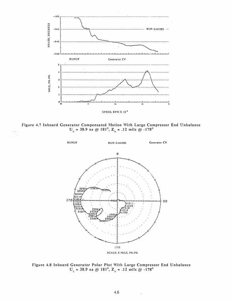
Fig 4.7 represents the absolute motion of the inboard generator bearing. The large
unbalance at the compressor end of the gas turbine causes little excitation of the
generator first critical speed at 1,300 RPM. There is an observed rotor casing mode at
2,300 RPM. The application of the large weight at the compressor station causes a high
excitation of the generator second critical speed at 3,200 RPM. The amplitude of motion
at the genera tor in board bearing is well behaved. Above 3,200 RPM, the amplitude reduces
as would be expected when passing through the second critical speed. Fig 4.8 represents
the polar diagram for the inboard generator bearing.
Fig 4.9 represents the absolute amplitude and phase angle change at the outboard
generator bearing with the slow roll vector subtracted. The generator second critical
speed is clearly seen at 3,100 RPM. Fig 4.10 represents the generator outboard bearing polar diagram. A comparison of the polar diagrams in Figs 4.8 and 4.10 for the inboard
and outboard generator bearings respectively, clearly shows that at 3,100 RPM the motion
at these bearings is out of phase. This is an indication that the generator is operating on
its second critical speed.
4.4 Exciter - Generator Non-linear Jump Response Due to Seal Rub
Fig 4.11 represents the absolute motion at the exciter end with and without run-out subtraction. A non-linear jump is observed at the exciter end at 2,300 RPM. This may
have been due to a seal rub. The exciter end also indicates that a generator critical speed occurs around 3,300 RPM. Fig 4.12 represents the polar diagram for the exciter end. Note
that the exciter end is 180° out of phase to the outboard bearing at 3,200 RPM and in
phase to the inboard bearing.
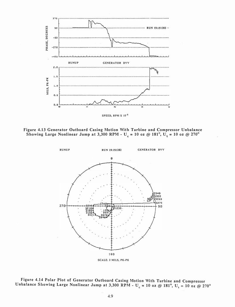
Fig 4.13 represents motion at the outboard generator bearing for one of the
unbalance runs on the W501 gas turbine. In this particular run, a non-linear jump was
observed at the generator and exciter end at 3,200 RPM. This non-linear jump is clearly seen in the polar diagram of Fig 4.14. When viewed in the polar plane, it can be seen that the magnitude of the amplitude change is much more severe. The magnitude of the nonlinear jump is 2.7 mils. After the jump occurs, the phase angle change is erratic and in
4.5
VJ "'
"'
-190 •...•..•............................................................. · .............................•....••........
p,: -1'Cl •.•••••••.•.•.••••••••••.. ..•.••.••••.••.•••.•••••••.••.•••••••••..••••••••...••••.• RUN 3:141282 ···
"'
Cl
VJ
<
= ""
RUNUP Generator CV
s ... · ......................................................................................... .................. .
� ........................ -······························································ .. ·····················
z ••••..••.•••..•••••...•..••..•.•.....••••••.•••.••••.••• ··•···•·•··••·•
SPEED, RPM X 10·•
Figure 4.7 Inboard Generator Compensated Motion With Large Compressor End Unbalance U = 38.9 oz@ 181°, Z = .12 mils @ -178°
C O
RUNUP RUN 3:141282 G en<ra tor CV
0
\_
90
�··.-----...1---
180
SCALE: S MILS, PK-PK
Figure 4.8 Inboard Generator Polar Plot With Large Compressor End Unbalance U = 38.9 oz @ 181 °, Z = .12 mils @ -178°
C O
4.6

rn ...i
-27C, ••••••••••••••••••••••••••••••••••••••••••••••••••••••••••••••••••••••••••••••••••••••••••••• •••••••••••••••••••
� RUN 3:141282 ··•·
� -�50
RUNUP DY MOTION
3 ··················································································-················.···········-··
� 2 •••••••.•••••••••••••••••••••••••••••••••••••••••••••••.•••••••.••••••••••••.•••. .•••••• •.•••••••••••••••••••
aL-...��-'-=...�.....:..i.���.,_._��_._�� ...... ����������
SPEED, RPM X 10·!
Figure 4.9 Generator Outboard l\lotion With Large Compressor End Unbalance U = 38.9 oz @ 181 °, Z = 0.09 mils @ -203°
C O
RUNUP RUN 3:141282 GENERATOR DY
0
. . . .
180
SCALE: 3 MILS, PK-PK
Figure 4.10 Generator Outboard Polar Motion With Large Compressor End Unbalance U = 38.9 oz @ 181°, Z = 0.09 mils @ -203°
C O
4.7

91) ••••••••••••••••••••••••••••••••••••••••••••••••••••••••••••••••••••••••••••••••••••••••••••• ·•••••••••••••••••••
RUN 3:141282 o ...........•.........•..........•....•••...........•..•........••. . .....•........... Solid: Comp ...... .
Dashtd: Uncomp
-90 ·•·····•·••••·•·•·•··•••······••·•·•··•·••••·••····•••••••·•·•·· ..•...••••.....
ej" -1a0 <
0. -270 ·· ...... .
:;;;
··.
RUNUP EXCITER EV 2.0 .....................•.•...................•..•...••....•..............•....••...................................
1.5
1.0
0.5
/' ......
...........
........................................................................ ;... ····-·············
� ! , ', .,
UNCOMPENSATED ;·.. } \, . .,,,': .' !.
_ ..... _./• ......... ··· .... ,: ·"'·.,-�.·.
::
'._,
.... � :_ . . .. , .....
,,/; . ·•···· .. .--�---;
J
............ . ..... ····················
0.G���..__ui::...... ....... �.L.��-1..���.L...��._J..���.L...��.,_.��� "'
SPEED, RPM X 10-3
Figure 4.11 Absolute Exciter End Motion and Phase With Large Compressor End Unbalance Showing Seal Rub at 2,300 RPM - U = 38.9 oz@ 181°, Z = 0.72 mils@ -187°
C O
RUNUP
. .
RUN 3:141282
0
180
SCALE: 2 J\IILS, PK-PK
EXCITER EV
9B
Figure 4.12 Exciter Polar Diagram With Large Compressor End Unbalance Showing Seal Rub at 2,300 RPM - U = 38.9 oz@ 181°, Z = 0.72 mils@ -187°
C O
4.8
27C,
VJ 9tl
<oJ
<oJ -so
VJ
-270
-<SG
RUNUP GENERATOR DVV
2;0
1. 5 ..••.••...•..•...•.••••••••••••••••...•••••••.•••••••••••••.••••••••••.••.•.•.••..••••.••... ···············-····
1.e ·········································································-··········--······ ····················
SPEED, RPM X 10·'
Figure 4.13 Generator Outboard Casing Motion With Turbine and Compressor Unbalance Showing Large Nonlinear Jump at 3,300 RPM - Uc = 10 oz@ 181°, Ut = 10 oz@ 270°
RUNUP RUN 19:151282 GENERATOR DVV
0
180
SCALE: 2 MILS, PK-PK
Figure 4.14 Polar Plot of Generator Outboard Casing Motion With Turbine and CompressorUnbalance Showing Large Nonlinear Jump at 3,300 RPM - U = 10 oz @ 181°, U = 10 oz @ 270°
c t
4.9

the direction of rotation. This is an indication of a seal rub at the exciter-genera tor location. When this occurs, the influence coefficients throughout the entire machine are shifted. The turbine-generator can not be accurately balanced if a seal rub occurs.
These figures represent typical data obtained on a 70 MW turbine-generator. The turbine-generator was successfully balanced using the least squared error balancing program LSQBAL developed by Dr. Gunter. In order to successfully balance the turbinegenera tor, the data had to be recorded at several speeds and at various power levels. The OEM field engineer spent over three months attempting to balance unit #l without success. Accurate balancing of the W501 gas turbine is very difficult to accomplish without the use of a computer. This machine is very sensitive to thermal bowing and seal rubs due to the operation of critical speeds in the operating speed range.
4.5 Non-Linear Response of Exciter End
In the balancing runs performed on unit #2, non-linear response was encountered at the exciter end. In the examimation of the polar plots of the inboard and outboard generator bearings, a critical speed around 3,400 RPM appeared. When the rotor speed was increased above 3,400 RPM, the amplitude of motion reduced. The polar diagram went through a 90° phase shift when passing through the critical speed. However, at the exciter end, the response and the influence coefficients at 3,600 RPM were highly dependent on the unbalance level.
Fig 4.15 represents the polar diagram obtained on the exciter end with unbalance of 93 grams at 65°. Fig (4.15) represents the analogue polar plot of the exciter amplitude and phase. The turbine second critical speed at 2,700 RPM is clearly evident. The generator second critical speed at 3,300 RPM is not apparent. Instead of the rotor amplitude "turning the corner", the motion increases rapidly outward with little phase change. This behavior is highly non-linear and also suggests the presence of a third exciter critical speed above 3,600 RPM. The amplitude of motion increased until the 7 mil limit was reached. At this point the turbine-generator was tripped off line. When this type of non-linear behavior occurs, the exciter end influence coefficient increases by a factor of five over the response characteristics for low levels of unbalance. This makes balancing the exciter end more complex because of the variation of the influence coefficients with unbalance level. In unit #2, it was found that the placement of two washers at the exciter balance plane at a deviation of 45° from the correct balance location could shut down a 60 ton turbine-generator. Redesign of the exciter end bearing may alleviate some of the non-linear characteristics encountered in balancing.
4.10

Start up
I
KP
Figure 4.15 Exciter Bearing Motion With 93 Gm @ 65 Deg Showing
Nonlinear Response Above 3,300 RPM
CT-42 RUN 12134
5 MILS Full Scale
90°
180°

V. FIELD BALANCING 70 MW TURBINE-GENERATORS
5.1 Influence Coefficients
The method used to balance the 70 MW turbine-generators was by means of the
multi-plane least squared error influence coefficient procedure with constraints. In the
influence coefficient procedure, trial weights are placed at various locations along the
shaft. A particular weight is placed at a location such as the coupling, turbine or
compressor end of the gas turbine, or exciter end of the generator and the resulting response measured at 5 stations and various speeds after the weight has been applied. By subtracting the vector difference of the amplitude at a station before and after the
application of the trial weight, an influence coefficient is generated for that station.
The influence coefficients are speed dependent. That is, the influence coefficients at one speed are not the same at a lower or higher speed. This is because the rotor has various critical speeds in its operating speed range. It is therefore important to have an understanding of the critical speed mode shapes of the system. For example, at a given
speed, a balance plane may be located at a nodal point and, hence, has very little influence on the balancing at that speed. The coupling plane, for example, has very little influence on the gas turbine first critical speed around 1,100 RPM, but has a substantial influence at 3,200 RPM. In the balancing technique employed by the OEM on unit #l, data only at running speed was used. In the balancing procedure used by the authors, various speed ranges were incorporated, as well as various probe readings. This balancing procedure is called the LEAST SQUARED ERROR BALANCING METHOD. The computer aided balancing procedure has been extended to include one-shot balancing (no trial weights) based on previous runs of the same or similar machines, and also has the capability to
balance without removing trial weights. In order to perform this type of calculation, a
high speed micro-computer is employed. The balancing procedure employed by the OEM for unit #I was simple single-plane balancing at the running speed.
In the theory of balancing, the system is assumed to be linear. This implies that if a balance calibration weight is doubled, the influence coefficients remain constant. From an examination of the experimental data, it was observed that the influence coefficients
are not constant at a particular speed, but are dependent upon various factors. The nonlinearity in the system can be caused by several factors. It is felt that non-linear rotor
response has caused some balancing problems with the 70 MW gas turbine-generators in the past. Some of the non-linearities that cause a deviation of the influence coefficients
from a linear system are coupling misalignment, generator seal rubs, thermal bowing due
to power level, and non-linear fluid film bearings. In spite of these various non-linear effects, successful balance of the various turbine-generators was achieved because of the application of the LEAST SQUARED ERROR BALANCING procedure, which minimizes the re
sponse at the various speeds selected.
5.2 Compressor End Balancing Calculations
Figure 4.1 represents the gas turbine hot end motion with approximately 39 oz of
balance correction applied to the compressor balance plane. The vibration levels with this
large correction at the compressor plane resulted in unacceptably high gas turbine vibrations. In the first balancing run performed by the authors on unit #l, two of the balance
weights were removed at the compressor location. Table 5.1 represents a typical calculation of the balancing correction if only one data set is used (simple single-plane balancing). In this example, the turbine end data was used to calculate a balancing
5.1
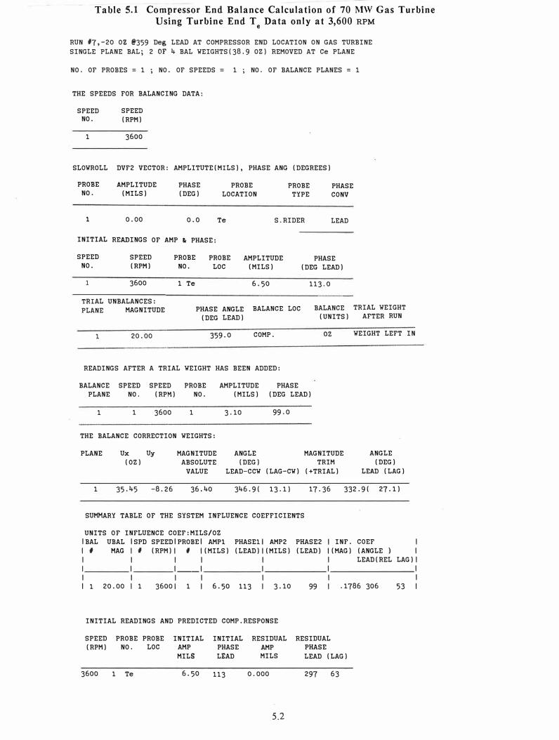
Table 5.1 Compressor End Balance Calculation of 70 MW Gas Turbine Using Turbine End T
e Data only at 3,600 RPM
RUN #7,-20 OZ @359 Deg LEAD AT COMPRESSOR END LOCATION ON GAS TURBINE
SINGLE PLANE BAL; 2 OF 4 BAL WEIGHTS(38,9 OZ) REMOVED AT Ce PLANE
NO. OF PROBES= 1 ; NO. OF SPEEDS= 1 ; NO. OF BALANCE PLANES = 1
THE SPEEDS FOR BALANCING DATA:
SPEED SPEED NO. (RPM)
1 3600
SLOWROLL DVF2 VECTOR: AMPLITUTE(MILS), PHASE ANG (DEGREES)
PROBE NO.
AMPLITUDE (MILS)
PHASE (DEG)
PROBE LOCATION
PROBE TYPE
PHASE CONV
l 0.00 0.0 Te S.RIDER LEAD
INITIAL READINGS OF AMP le PHASE:
SPEED SPEED PROBE PROBE AMPLITUDE PHASE NO. (RPM) NO. LOC (MILS) (DEG LEAD)
1 3600 1 Te 6.50 113.0
TRIAL UNBALANCES: PLANE MAGNITUDE PHASE ANGLE BALANCE LOC BALANCE
(DEG LEAD) (UNITS)
1 20.00 359.0 COMP. oz
READINGS AFTER A TRIAL WEIGHT HAS BEEN ADDED:
BALANCE SPEED SPEED PROBE AMPLITUDE PHASE PLANE NO. (RPM) NO. (MILS) (DEG LEAD)
1 1 3600 1 3.10 99.0
THE BALANCE CORRECTION WEIGHTS:
PLANE Ux Uy MAGNITUDE ANGLE MAGNITUDE (OZ) ABSOLUTE (DEG) TRIM
VALUE LEAD-CCW (LAG-CW) (+TRIAL)
TRIAL WEIGHT AFTER RUN
WEIGHT LEFT IN
ANGLE (DEG)
LEAD (LAG)
1 35.45 -8.26 36.40 346.9( 13.1) 17.36 332.9( 27.1)
SUMMARY TABLE OF THE SYSTEM INFLUENCE COEFFICIENTS
UNITS OF INFLUENCE COEF:MILS/OZ IBAL UBAL ISPD SPEEDIPROBEI AMPl PHASEll AMP2 PHASE2 I INF. COEF
I # MAG I I (RPM) I I I (MILS) (LEAD) I (MILS) (LEAD) I (MAG) (ANGLE I I
I I I I I I LEAD(REL LAG) I I I I __ I I I I I I I I I I 1 20.00 I 1 36001 1 I 6.50 113 I 3.10 99 I .1786 306
INITIAL READINGS AND PREDICTED COMP.RESPONSE
SPEED PROBE PROBE (RPM) NO. LOC
3600 1 Te
INITIAL AMP MILS
INITIAL PHASE LEAD
6.50 113
RESIDUAL RESIDUAL AMP PHASE MILS LEAD (LAG)
0.000
5.2
297 63
I I
53 I

Table 5.2 Compressor End Balance Calculation Using Compressor C and e
Turbine T Data at Various Speeds - U = 20 oz @ 359° - Initial Vibration Data e c
TRIAL WEIGHT LEFT IN PLACE AFTER RUN
NO. OF PROBES = 2 ; NO. OF SPEEDS= 6 NO. OF BALANCE PLANES 1
THE SPEEDS FOR BALANCING DATA:
SPEED
NO.
1
SPEED
(RPM)
1066 TURBINE lST CRIT
2 1702 GENERATOR lST CHIT
3 2300 TURBINE 2ND CHIT
4 2756 TURBINE-GENERATOR CHIT
5 3600 RUNNING SPEED: COLD OMW
6 3600 RUNNING SPEED: HOT 70MW
SLOWROLL DVF2 VECTOR: AMPLITUTE(MILS), PHASE ANG
PROBE AMPLITUDE PHASE PROBE
NO. (MILS) (DEG) LOCATION
(DEGREES)
PROBE PHASE
TYPE CONV
1 0.00 0.0 Ce S RIDER LEAD -----------------------------------------------------------------
2 0.00 0.0 Te S RIDER LEAD
INITIAL READINGS OF AMP� PHASE:
SPEED
NO.
1
1
2
2
3
3
4
4
5
5
6
6
SPEED
(RPM)
1066
1066
1702
1702
2300
2300
2756
2756
3600
3600
3600
3600
PROBE PROBE AMPLITUDE NO. LOC (MILS)
1 Ce 1. 70
2 Te 4.60
1 Ce 2.80
2 Te
1 Ce 3.90
2 Te 3.70
1 Ce 4.50
2 Te
1 Ce 5.40
2 Te
1 Ce 1.98
2 Te 5.70
5.3
PHASE
(DEG LEAD)
339.0
54.0
226.0
10.0
145.0
333.0
103.0
302.0
74.0
113.0
98.0
114.0
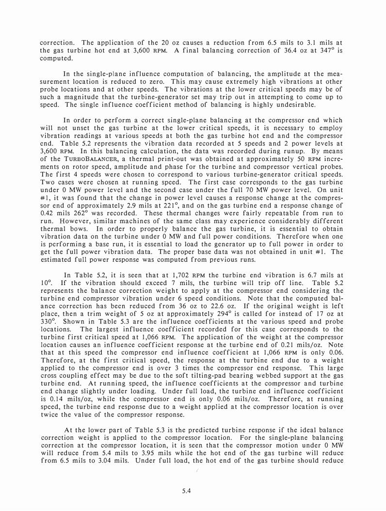
correction. The application of the 20 oz causes a reduction from 6.5 mils to 3.1 mils at
the gas turbine hot end at 3,600 RPM. A final balancing correction of 36.4 oz at 347°
is
computed.
In the single-plane influence computation of balancing, the amplitude at the mea
surement location is reduced to zero. This may cause extremely high vibrations at other
pro be locations and at other speeds. The vibrations at the lower critical speeds may be of
such a magnitude that the turbine-generator set may trip out in attempting to come up to
speed. The single influence coefficient method of balancing is highly undesirable.
In order to perform a correct single-plane balancing at the compressor end which
will not unset the gas turbine at the lower critical speeds, it is necessary to employ
vibration readings at various speeds at both the gas turbine hot end and the compressor
end. Table 5.2 represents the vibration data recorded at 5 speeds and 2 power levels at 3,600 RPM. In this balancing calculation, the data was recorded during runup. By means
of the TURBOBALANCER, a thermal print-out was obtained at approximately 50 RPM incre
ments on rotor speed, amplitude and phase for the turbine and compressor vertical probes.
The first 4 speeds were chosen to correspond to various turbine-generator critical speeds.
Two cases were chosen at running speed. The first case corresponds to the gas turbine
under O MW power level and the second case under the full 70 MW power level. On unit
# 1, it was found that the change in power level ca uses a response change at the compres
sor end of approximately 2.9 mils at 221 °, and on the gas turbine end a response change of
0.42 mils 262° was recorded. These thermal changes were fairly repeatable from run to
run. However, similar machines of the same class may experience considerably different
thermal bows. In order to properly balance the gas turbine, it is essential to obtain
vibration data on the turbine under O MW and full power conditions. Therefore when one
is performing a base run, it is essential to load the generator up to full power in order to get the full power vibration data. The proper base data was not obtained in unit #1. The
estimated full power response was computed from previous runs.
In Table 5.2, it is seen that at 1,702 RPM the turbine end vibration is 6.7 mils at
10°. If the vibration should exceed 7 mils, the turbine will trip off line. Table 5.2
represents the balance correction weight to apply at the compressor end considering the
turbine end compressor vibration under 6 speed conditions. Note that the computed balance correction has been reduced from 36 oz to 22.6 oz. If the original weight is left
place, then a trim weight of 5 oz at approximately 294° is called for instead of 17 oz at
330°
. Shown in Table 5.3 are the influence coefficients at the various speed and probe
locations. The largest influence coefficient recorded for this case corresponds to the
turbine first critical speed at 1,066 RPM. The application of the weight at the compressor
location causes an influence coefficient response at the turbine end of 0.21 mils/oz. Note that at this speed the compressor end influence coefficient at 1,066 RPM is only 0.06.
Therefore, at the first critical speed, the response at the turbine end due to a weight
applied to the compressor end is over 3 times the compressor end response. This large cross coupling effect may be due to the soft tilting-pad bearing webbed support at the gas
turbine end. At running speed, the influence coefficients at the compressor and turbine
end change slightly under loading. Under full load, the turbine end influence coefficient
is 0.14 mils/oz, while the compressor end is only 0.06 mils/oz. Therefore, at running
speed, the turbine end response due to a weight applied at the compressor location is over
twice the value of the compressor response.
At the lower part of Table 5.3 is the predicted turbine response if the ideal balance correction weight is applied to the compressor location. For the single-plane balancing
correction at the compressor location, it is seen that the compressor motion under O MW
will reduce from 5.4 mils to 3.95 mils while the hot end of the gas turbine will reduce from 6.5 mils to 3.04 mils. Under full load, the hot end of the gas turbine should reduce
(
5.4

Table 5.3 Compressor End Balance Calculations and Influence Coefficients Using Compressor C and Turbine T Data at Various Speeds
e e
RUN #7 SHOT AT Ce: 20 OZ@ 359 DEG ON COMPRESSOR BALANCE PLA E TRIAL WEIGHT LEFT IN PLACE AFTER RUN
THE BALANCE CORRECTION WEIGHTS:
PLANE Ux Uy (OZ)
MAGNITUDE ANGLE MAGNITUDE ABSOLUTE (DEG) TRIM
VALUE LEAD-CCW (LAG-CW) (+TRIAL)
ANGLE (DEG)
LEAD (LAG)
1 22.09 -4.97 22.64 34 7. 3 ( 12 . 7) 5.08 294.4( 65.6)
SUMMARY TABLE OF THE SYSTEM INFLUENCE COEFFICIENTS
UNITS OF INFLUENCE COEF:MILS/OZ IBAL UBAL ISPD SPEEDIPROBEI AMPl PHASEl l AMP2 PHASE2 I INF. COEF I I # MAG I # (RPM) I # I (MILS) (LEAD) I (MILS) (LEAD) I (MAG) (ANGLE ) I I I I I I I LEAD ( REL LAG ) I I I '�� l �����- 1 ������ 1 ��������' I I I I I I I I 1 20. oo I 1 1066 I 1 I 1. 70 339 I 2. 60 313 I . 0653 279 80 I I 1 20. oo I 1 1066 I 2 I 4. 60 54 I 5. 90 7 I . 2177 317 42 I I 1 20. oo I 2 17021 1 I 2. 80 226 I 3. 90 232 I . 0577 248 111 I I 1 20.00 I 2 17021 2 I 6.70 10 I 4.40 4 I .1185 202 157 I I 1 20.00 I 3 23001 1 I 3.90 145 I 4.20 160 I .0549 228 131 I I 1 20. oo I 3 2300 I 2 I 3. 70 333 I 2. 80 340 I . 0491 134 225 I I 1 20.00 I 4 27561 1 I 4.50 103 I 3.50 120 I .0771 242 117 I I 1 20.00 I 4 2756 1 2 I 4.70 302 I 5.40 325 I .1064 26 333 I I 1 20. oo I 5 3600 I 1 I 5. 40 74 I 4 .10 73 I . 0651 258 101 I I 1 20.00 I 5 36001 2 I 6.50 113 I 3.70 97 I .1558 313 46 I I 1 20. oo I 6 3600 I 1 I 1. 98 98 I 1. 50 141 I . 0676 230 129 I I 1 20.00 I 6 36001 2 I 5.70 114 I 3.10 99 I .1411 312 47 I
INITIAL READINGS AND PREDICTED COMP.RESPONSE
SPEED PROBE PROBE INITIAL INITIAL RESIDUAL RESIDUAL (RPM) NO. LOC AMP PHASE AMP PHASE
MILS LEAD MILS LEAD (LAG)
1066 1 Ce 1. 70 339 2.567 306 54 1066 2 Te 4.60 54 5.520 357 3 1702 1 Ce 2.80 226 4.095 229 131 1702 2 Te 6.70 10 4.018 10 350 2300 1 Ce 3.90 145 4.479 160 200 2300 2 Te 3.70 333 2.819 345 15 2756 1 Ce 4.50 103 3.729 125 235 2756 2 Te 4.70 302 5.938 325 35 3600 1 Ce 5.40 74 3.948 77 283 3600 2 Te 6.50 113 3.037 104 256 3600 1 Ce 1.98 98 1.820 145 215 3600 2 Te 5.70 114 2.530 108 252
5.5
from 5.7 mils to 2.53 mils. It is of interest to note that the application of this correction
weight will cause the compressor end turbine motion at the first critical speed of 1,066
RPM to increase slightly. At the turbine-generator critical speed of 2,756 RPM, the turbine
amplitude will increase from 4.7 to 5.9 mils.
Since the influence coefficients at the various probes and speed conditions have
been generated by the computer, it is possible to compute the new response of the rotor
with an arbitrary placement of weight at the compressor location. In Table 5.4, the trim
balance weight of 17.36 oz at 333° was computed to see its response on the rotor. This
value was predicted using only turbine end data at 3,600 RPM. If this weight were applied
to the rotor, then an amplitude of over 7.7 mils would be encountered at the gas turbine first critical speed at the hot end. This would trip the machine off line and it would not be able to come up to speed. Also, a 7 mil amplitude would occur at the turbine-generator critical speed at 2,756 RPM. It is clearly apparent that balancing predictions based on single speed readings are entirely unsatisfactory for a gas turbine-generator.
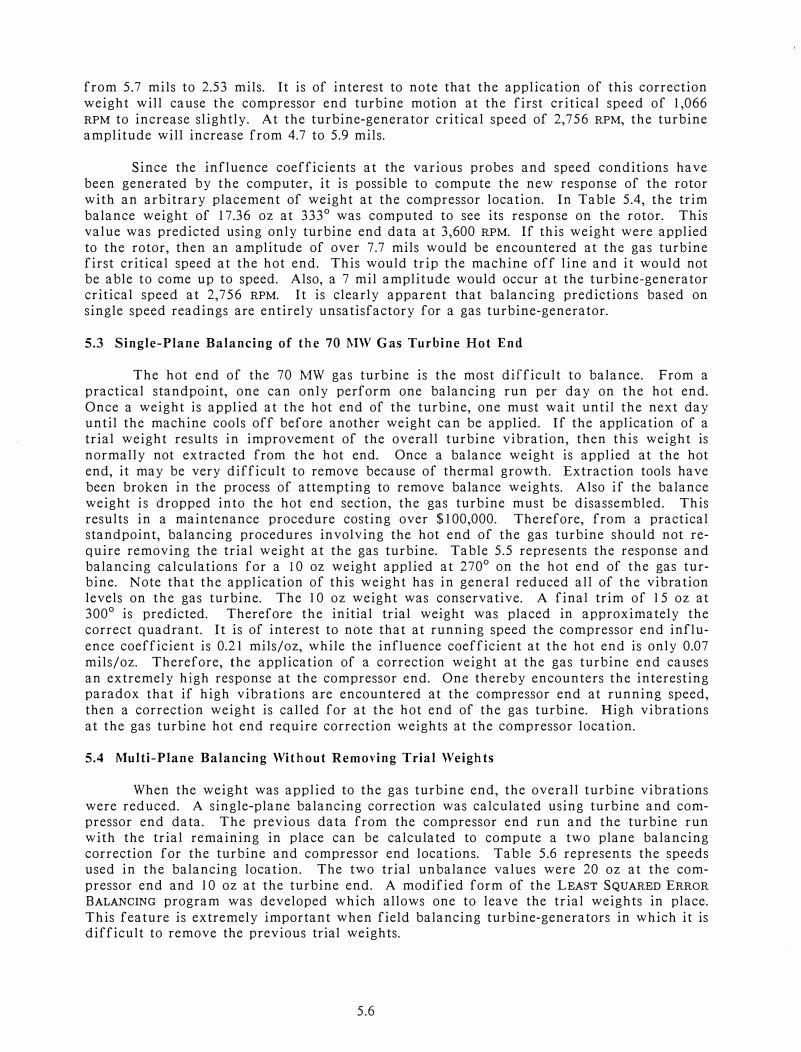
5.3 Single-Plane Balancing of the 70 MW Gas Turbine Hot End
The hot end of the 70 MW gas turbine is the most difficult to balance. From a
practical standpoint, one can only perform one balancing run per day on the hot end.
Once a weight is applied at the hot end of the turbine, one must wait until the next day until the machine cools off before another weight can be applied. If the application of a trial weight results in improvement of the overall turbine vibration, then this weight is
normally not extracted from the hot end. Once a balance weight is applied at the hot
end, it may be very difficult to remove because of thermal growth. Extraction tools have
been broken in the process of attempting to remove balance weights. Also if the balance
weight is dropped into the hot end section, the gas turbine must be disassembled. This results in a maintenance procedure costing over $100,000. Therefore, from a practical standpoint, balancing procedures involving the hot end of the gas turbine should not re
quire removing the trial weight at the gas turbine. Table 5.5 represents the response and balancing calculations for a 10 oz weight applied at 270
° on the hot end of the gas turbine. Note that the application of this weight has in general reduced all of the vibration levels on the gas turbine. The 10 oz weight was conservative. A final trim of 15 oz at 300
°
is predicted. Therefore the initial trial weight was placed in approximately the correct quadrant. It is of interest to note that at running speed the compressor end influ
ence coefficient is 0.21 mils/oz, while the influence coefficient at the hot end is only 0.07
mils/oz. Therefore, the application of a correction weight at the gas turbine end causes
an extremely high response at the compressor end. One thereby encounters the interesting paradox that if high vibrations are encountered at the compressor end at running speed,
then a correction weight is called for at the hot end of the gas turbine. High vibrations
at the gas turbine hot end require correction weigh ts at the compressor location.
5.4 Multi-Plane Balancing Without Removing Trial Weights
When the weight was applied to the gas turbine end, the overall turbine vibrations
were reduced. A single-plane balancing correction was calculated using turbine and compressor end data. The previous data from the compressor end run and the turbine run
with the trial remaining in place can be calculated to compute a two plane balancing correction for the turbine and compressor end locations. Table 5.6 represents the speeds used in the balancing location. The two trial unbalance values were 20 oz at the com
pressor end and 10 oz at the turbine end. A modified form of the LEAST SQUARED ERROR BALANCING program was developed which allows one to leave the trial weights in place.
This feature is extremely important when field balancing turbine-generators in which it is difficult to remove the previous trial weights.
5.6
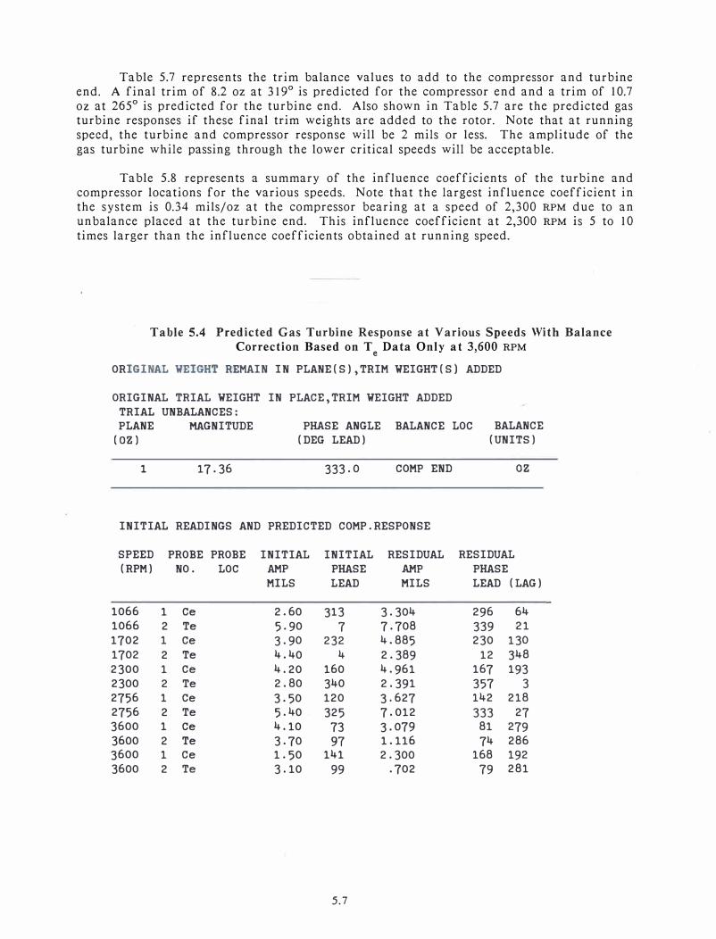
Table 5.7 represents the trim balance values to add to the compressor and turbine
end. A final trim of 8.2 oz at 319° is predicted for the compressor end and a trim of 10.7
oz at 265°
is predicted for the turbine end. Also shown in Table 5.7 are the predicted gas
turbine responses if these final trim weights are added to the rotor. Note that at running
speed, the turbine and compressor response will be 2 mils or less. The amplitude of the
gas turbine while passing through the lower critical speeds will be acceptable.
Table 5.8 represents a summary of the influence coefficients of the turbine and
compressor locations for the various speeds. Note that the largest influence coefficient in
the system is 0.34 mils/oz at the compressor bearing at a speed of 2,300 RPM due to an
unbalance placed at the turbine end. This influence coefficient at 2,300 RPM is 5 to 10
times larger than the influence coefficients obtained at running speed.
Table 5.4 Predicted Gas Turbine Response at Various Speeds With Balance
Correction Based on T Data Only at 3,600 RPM e
ORIGINAL WEIGHT REMAIN IN PLANE(S),TRIM WEIGHT(S) ADDED
ORIGINAL TRIAL WEIGHT IN PLACE,TRIM WEIGHT ADDED TRIAL UNBALANCES: PLANE
(OZ)
1
MAGNITUDE
17.36
PHASE ANGLE BALANCE LOC (DEG LEAD)
333.0 COMP END
INITIAL READINGS AND PREDICTED COMP.RESPONSE
BALANCE (UNITS)
oz
SPEED PROBE PROBE INITIAL INITIAL RESIDUAL RESIDUAL (RPM) NO. LOC AMP PHASE AMP PHASE
MILS LEAD MILS LEAD (LAG)
1066 1 Ce 2.60 313 3.304 296 64 1066 2 Te 5.90 7 7.708 339 21 1702 1 Ce 3.90 232 4.885 230 130
1702 2 Te 4.40 4 2.389 12 348
2300 1 Ce 4.20 160 4.961 167 193 2300 2 Te 2.80 340 2.391 357 3 2756 1 Ce 3.50 120 3.627 142 218 2756 2 Te 5.40 325 7.012 333 27 3600 1 Ce 4.10 73 3.079 81 279 3600 2 Te 3.70 91 1.116 74 286
3600 1 Ce 1.50 141 2.300 168 192 3600 2 Te 3.10 99 .702 79 281
5.7

Table 5.5 Turbine End Balance Calculation and Predicted Response
Based on T and C Data at Various Speeds e e
BALANCE DATA WITH 4 SPEEDS WITH Ce� Te MEASUREMENTS,10 OZ@ 270 DEG SINGLE PLANE CORRECTION,3600 ,2850 ,1054,1107 RPM- 4 SPEED SETS
THE BALANCE CORRECTION WEIGHTS:
PLANE Ux Uy
(OZ) MAGNITUDE ANGLE MAGNITUDE ABSOLUTE (DEG) TRIM
VALUE LEAD-CCW (LAG-CW) (+TRIAL)
ANGLE (DEG)
LEAD (LAG)
1 7.72 -23.37 24.61 288. 3 ( 71. 7) 15.44 300.0( 60.0)
SUMMARY TABLE OF THE SYSTEM INFLUENCE COEFFICIENTS
UNITS OF INFLUENCE COEF:MILS/OZ IBAL UBAL SPD SPEEDIPROBEI AMPl PHASEll AMP2 PHASE2 I INF. COEF
I fl MAG fl (RPM) I # I (MILS) (LEAD) I (MILS) (LEAD) I (MAG) (ANGLE ) I I
I I I I I LEAD(REL LAG) I I I __ I I I I I I I I I I I 1 10.00 1 36001 1 I 4.10 73 I 2.60 101 I .2178 309 321 I I 1 10.00 1 36001 2 I 3.70 97 I 3.40 95 I .0325 28 242 I I 1 10.00 2 28501 1 I 3.40 114 I 1.40 91 I .2181 39 231 I
I 1 10.00 2 28501 2 I 5.50 320 I 4.30 327 I .1339 207 63 I
I 1 10.00 3 10541 1 I 2.60 313 I 1.80 319 I .0831 210 60 I I 1 10.00 3 10541 2 I 5.90 7 I 4.30 15 I .1748 257 13 I I 1 10.00 4 11071 1 I 2.50 284 I 1.80 292 I .0760 175 95 I I 1 10.00 4 11071 2 I 4.50 351 I 3.40 4 I .1412 228 42 I
INITIAL READINGS AND PREDICTED COMP.RESPONSE
SPEED PROBE PROBE INITIAL INITIAL RESIDUAL RESIDUAL (RPM) NO. LOC AMP PHASE AMP PHASE
MILS LEAD MILS LEAD (LAG)
3600 1 CE#4BRG 4.10 73 1.803 199 161 3600 2 Te#5BRG 3.70 97 3.128 88 272 2850 1 CE#4BRG 3.40 114 3.113 3 357 2850 2 Te#5BRG 5.50 320 2.233 327 33 1054 1 CE#4BRG 2.60 313 .592 295 65 1054 2 Te#5BRG 5.90 7 1.607 12 348
1107 1 CE#4BRG 2.50 284 .631 287 73 1107 2 Te#5BRG 4.50 351 1.431 28 332
5.8

Table 5.6 Compressor and Turbine Two Plane Balancing Calculation Without
Removing Trial Weights - Speed Values and Trial Unbalances
RU #7 SHOT AT Ce: 20 OZ@ 359 DEG; RUN #8 SHOT AT Te: 10 OZ@ 270 DEG
TRIAL WEIGHTS LEFT IN PLACE AFTER RUN
NO. OF PROBES = 2 ; NO. OF SPEEDS = 6 NO. OF BALANCE PLANES = 2
THE SPEEDS FOR BALANCING DATA:
SPEED NO.
1
SPEED (RPM)
1066 TURBINE lST CRIT
2 1702 GENERATOR lST CRIT
3 2300 TURBINE 2ND CRIT
4 2756 TURBINE-GENERATOR CRIT
5 3600 RUNNING SPEED: COLD OMW
6 3600 RUNNING SPEED: HOT 70MW
SLOWROLL DVF2 VECTOR: AMPLITUTE(MILS), PHASE ANG (DEGREES)
PROBE AMPLITUDE PHASE PROBE PROBE NO. (MILS) (DEG) LOCATION TYPE
1 0.00 0.0 Ce s RIDER
PHASE CONV
LEAD -----------------------------------------------------------------
2 0.00 o.o Te S RIDER LEAD
TRIAL UNBALANCES: PLANE MAGNITUDE
1 20.00
PHASE ANGLE BALANCE LOC (DEG LEAD)
359.0 COMP END
BALANCE TRIAL WEIGHT (UNITS) AFTER RUN
oz WEIGHT LEFT IN ----------------------------------------------------------------
10.00 270.0 TURBINE END oz WEIGHT LEFT IN
5.9
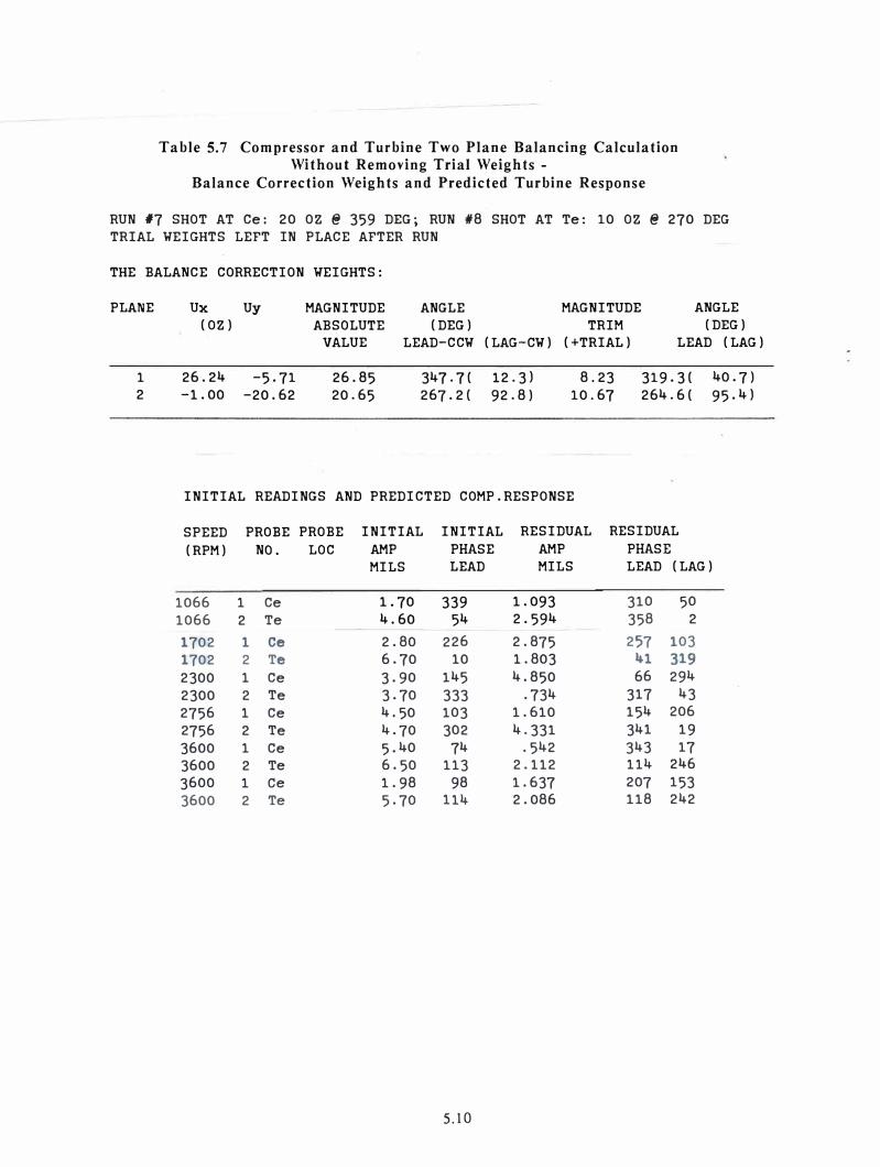
Table 5.7 Compressor and Turbine Two Plane Balancing Calculation Without Removing Trial Weights -
Balance Correction Weights and Predicted Turbine Response
RUN #7 SHOT AT Ce: 20 OZ@ 359 DEG; RUN #8 SHOT AT Te: 10 OZ@ 270 DEG
TRIAL WEIGHTS LEFT IN PLACE AFTER RUN
THE BALANCE CORRECTION WEIGHTS:
PLANE Ux Uy MAGNITUDE ANGLE MAGNITUDE ANGLE
(OZ) ABSOLUTE (DEG) TRIM (DEG)
VALUE LEAD-CCW (LAG-CW) (+TRIAL) LEAD (LAG)
1 26.24 -5.71 26.85 347.7( 12.3) 8.23 319.3( 40.7)
2 -1.00 -20.62 20.65 267.2( 92.8) 10.67 264.6( 95.4)
INITIAL READINGS AND PREDICTED COMP.RESPONSE
SPEED PROBE PROBE INITIAL INITIAL RESIDUAL RESIDUAL
(RPM) NO. LOC AMP PHASE AMP PHASE
MILS LEAD MILS LEAD (LAG)
1066 1 Ce 1. 70 339 1.093 310 50
1066 2 Te 4.60 54 2.594 358 2
1702 1 Ce 2.80 226 2.875 257 103
1702 2 Te 6.70 10 1.803 41 319
2300 1 Ce 3.90 145 4.850 66 294
2300 2 Te 3.70 333 .734 317 43
2756 1 Ce 4.50 103 1.610 154 206
2756 2 Te 4.70 302 4.331 341 19
3600 1 Ce 5.40 74 .542 343 17
3600 2 Te 6.50 113 2.112 114 246
3600 1 Ce 1.98 98 1.637 207 153
3600 2 Te 5.70 114 2.086 118 242
5.10
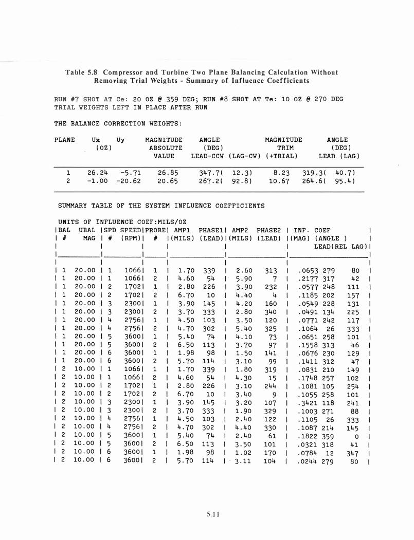
Table 5.8 Compressor and Turbine Two Plane Balancing Calculation Without Removing Trial Weights - Summary of Influence Coefficients
RUN #7 SHOT AT Ce: 20 OZ@ 359 DEG; RUN #8 SHOT AT Te: 10 oz@ 270 DEG
TRIAL WEIGHTS LEFT IN PLACE AFTER RUN
THE BALANCE CORRECTION WEIGHTS:
PLANE Ux Uy MAGNITUDE ANGLE MAGNITUDE ANGLE (OZ) ABSOLUTE (DEG) TRIM (DEG)
VALUE LEAD-CCW (LAG-CW) (+TRIAL) LEAD (LAG)
1 26.24 -5.71 26.85 347.7( 12.3) 8.23 319.3( 40,7) 2 -1.00 -20.62 20.65 267.2( 92,8) 10.67 264.6( 95.4)
SUMMARY TABLE OF THE SYSTEM INFLUENCE COEFFICIENTS
UNITS OF INFLUENCE COEF:MILS/OZ
IBAL UBAL ISPD SPEED PROBE! AMPl PHASEll AMP2 PHASE2 I INF. COEF I I # MAG I # (RPM) # I (MILS) (LEAD) I (MILS) (LEAD) I (MAG) (ANGLE I I I I .1 I LEAD(REL LAG) I I I I I I I
I I I I 1 20.00 I 1 1066 1 1. 70 339 I 2.60 313 I .0653 279 BO I 1 20.00 I 1 1066 2 4.60 54 I 5.90 7 I .2177 317 42 I 1 20.00 I 2 1702 1 2.80 226 I 3.90 232 I .0577 248 111 I
1 20.00 2 1702 2 6.70 10 I 4.40 4 I .1185 202 157 I 1 20.00 3 2300 1 3.90 145 I 4.20 160 I ,0549 228 131 I 1 20.00 3 2300 2 3.70 333 I 2.80 340 I .0491 134 225 I 1 20.00 4 2756 1 4.50 103 I 3.50 120 .0771 242 117 I 1 20.00 4 2756 2 4.70 302 I 5.40 325 .1064 26 333 I 1 20.00 5 3600 1 5,40 74 I 4.10 73 .0651 258 101 I 1 20.00 5 3600 2 6.50 113 I 3.70 97 .1558 313 46 I 1 20.00 6 3600 1 1.98 98 I 1.50 141 .0676 230 129 I 1 20.00 6 3600 2 5.70 114 I 3.10 99 .1411 312 47 I 2 10.00 1 1066 1 1. 70 339 I 1.80 319 .0831 210 149 I 2 10.00 1 1066 2 4.60 54 I 4.30 15 .1748 257 102 I 2 10.00 2 1702 1 2.80 226 I 3.10 244 .1081 105 254 I
I 2 10.00 2 1702 2 6.70 10 I 3.40 9 .1055 258 101 I I 2 10.00 3 2300 1 3.90 145 I 3.20 107 . 3421 118 241 I I 2 10.00 3 2300 2 3.70 333 I 1.90 329 .1003 271 88 I I 2 10.00 4 2756 1 4.50 103 I 2.40 122 .1105 26 333 I I 2 10.00 4 2756 2 4.70 302 I 4.40 330 .1087 214 145 I I 2 10.00 5 3600 1 5.40 74 I 2.40 61 .1822 359 0 I I 2 10.00 5 3600 2 6.50 113 I 3.50 101 .0321 318 41 I I 2 10.00 6 3600 1 1. 98 98 I 1.02 170 .0784 12 347 I I 2 10.00 6 3600 2 5.70 114 I 3.11 104 .0244 279 80 I
5.11

VI. SUMMARY AND CONCLUSIONS ON PRACTICAL ASPECTS OF BALANCING
1. The difficulty experienced in balancing 70 MW Gas Turbine-Generators has been dueto more than conventional unbalance. Additional effects such as shaft bowing due tothermal effects, seal rubs, misalignment, and bearing non-linearity have been experienced.
2. Critical speeds should always be computed to determine the relative rotor mode shapesand the planes at which the rotor will or will not be sensitive to unbalance.
3. The field engineer supplied by the OEM was not furnished with the data on the combined turbine-generator critical speeds. He therefore did not attempt to balance the rotorusing modal weight distributions.
4. The OEM field engineer attempted to balance the gas turbine using only one turbineplane at a time with response data taken only at running speed. This procedure is inadequate to field balance the 70 MW gas turbine-generator.
5. The application of a single correction weight at the turbine or compressor end of thegas turbine will excite both the turbine first and second modes of the system.
6. The gas turbine proper has three balance planes which normally may be used forbalancing. In addition to the end planes at the compressor and at the gas turbine end,there is center plane where weights may be added. This center plane in the first installation was never used because the access cover was obscured by piping. In the secondinstallation the center balance location was available for balancing. This center plane ismost cffecpve for balancing the rotor motion in the speed range of 1,000 to 1,200 RPM.However, this plane should not be used to add corrections to the rotor motion above 2,500RPM. This is because the center plane location becomes a node point, and has little usefulinfluence on balancing
7. The application of balance weights at both the compressor and turbine end in phasehas an influence on the rotor center. This combination of trial weights will cause a largeresponse at the first critical speed in the range of 900 to 1,200 RPM, but only a smallresponse above 2,500 RPM. If this weight combination is used, then speed data only in the900 to 1,200 RPM should be used. If this weight combination is used to trim balance theturbine at running speed, then a large response at the first critical may be expected. It is
believed that when this weight combination was employed by the field service engineer onunit #l, the gas turbine developed a bow in the first mode.
8. The application of balance weights at both ends of the gas turbine, but out-of-phase, issometimes referred to as a dynamic correction, or shot, while the two weights in-phase aresometimes referred to as a static shot. The application of two weights at the compressorand gas turbine ends out-of-phase would have little to no effect on the rotor first modearound 1,000 RPM. This weight combination was never applied by the field service engineer. The application of a dynamic couple shot at 3,600 RPM would be most effective,whereas the application of a large static shot could cause rotor bowing, which it did.
9. The use of only two balancing planes is inadequate to properly balance the 70 MWturbine-generator. There appear to be six to seven rotor-casing modes in the system.There arc two modes each associated with the turbine and the generator. In additionthere are several rotor-casing modes in the system. The third free-free gas turbine modeon unit #l may have been close to running speed. This conclusion will be discussed in
greater detail later. As a result of all of these modes, it is physically impossible tobalance the turbine using only two planes.
6.1

10. The only additional plane available for balancing on unit #l was the couplinglocation. Previous to the balancing work of Gunter and Humphris,, the field serviceengineer did not attempt to utilize this plane for balancing. Analysis of the systemcritical speeds showed that the coupling location is not very eff cctive for balancing eitherthe turbine.first or second cri ticaJ speeds. However, the genera tor critical speed appearsaround 3,200 RPM. This location, hence, is very effective to use as a single planecorrection in the speed range of 3,200 to 3,600 RPM.
11. The generator second critical speed is clearly seen by the reversal in the phase of the
polar plots obtained at the two ends of the generator. However, it appears to be highly
impractical to field balance the generator except at the exciter end. The trim balancingof the coupling has a substantial influence on the attenuation of the generator secondcritical speed. No attempt should be make to balance the coupling below 3,200 RPM, as thecoupling has little influence on the gas turbine first and second critical speeds.
12. The theory of single plane and multi-plane balancing is based upon the assumptionthat the rotor bearing system response is a linear combination of the unbalances locatedalong the length of the rotor. The change in response due to the application of a trial orcalibration weight is referred to as an influence coefficient. These influence coefficientshave the units of response (in mils, velocity per unit of unbalance, oz, grams or oz-in.,etc.). In a truly linear system, the influence coefficients are independent of the magnitude of unbalance, and are functions only of speed. For the case of the W50 I gas turbine,the influence coefficients were found to be highly non-linear and variable. Some of thevarious reasons for the non-linearity or wide variations observed in the influence coefficients are non-linear fluid film bearings, thermal bow due to nonuniform expansion ofgas turbine and generator under load, rotor acceleration, coupling misalignment, rotorbolted up construction, flexible strut mounting or the turbine end tilting pad bearing,friction in the support legs of gas turbine casing, and rubbing at the seal location at thegenerator exciter end. All of the above factors cause the influence coefficients to deviate
from the ideal linear case.
13. The field service engineer attempted to balance the gas turbine by applying singleplane linear theory at running speed to the two balance planes independently. Thisprocedure is not accurate or sufficient to balance the gas turbine for several reasons.
First, the total number of planes is insufficient (three must be used), and also one mustuse more than a single measurement. This requires a least squared error computer pro
gram in order to perform the necessary balancing calculations.
14. The unit #l gas turbine was successfully balanced in two days using a least squarederror computer program developed for the HP 9845B computer. By means of the leastsquared error program, many data sets could be entered into the calculation to determinethe best fit over the speed range. These calculations were completed on site and within
minutes of the run. Therefore a balancing correction was immediately on hand for the
next run.
15. The balancing procedure used by the field engineer on unit #l was a single or two
plane procedure using only one set of speed data. For a more complicated balancingcalculation, it was necessary for him to call the main office in Atlanta to relay the data.Therefore the balancing data was not normally available until the next day. For the cases
where data was sent to the Atlanta field office to compute the balance shots, it appearsthat the field engineer did not relay any lower speed data which would have included the
effects of the gas turbine first and second critical speeds.
6.2

16. As a result of this balancing procedure, it required almost one week for the fieldservice engineer to get the turbine up to running speed. At this time 4 - 10 oz weights
were placed at the compressor balancing location. It is believed that this large concen
tration of balance weights in a single plane may have resulted in shaft bow at the rotor
first critical speed.
17. The least squared error program predicted that 3 of the 4 weights should be removed
for best balance over the speed range for unit #1. Balancing was improved when this was
done.
18. When balancing using only one plane at a time, there is a limit to the amount ofvibration reduction that one can achieve. It was observed in several cases, that theoptimum least squared error single plane balance correction value could result in therunning speed amplitude being slightly higher with the application of the balance correc
tion. This is because the least squared error method also takes into consideration the
vibration amplitude and phase at the lower speeds. · Any attempt to further reduce the
running speed amplitude by the single plane balancing method will result in higher ampli
tudes at lower speed. Excessive amounts of single plane correction using only running
speed data can bow the rotor at lower speeds.
19. When computing the rotor influence coefficients due to an applied weight at a plane,
the influence coefficient is computed by a vector subtraction of the two different runsbefore and after balancing, divided by the value of the balance weight. The influencecoefficient therefore is a complex number. The phase angle of the influence coefficient
is as important as the magnitude. For a linear repeatable system, both of these valuesmust be functions of speed only, and not the level of unbalance. The exciter influencecoefficients of unit #2 were found to be a found to be a highly non-linear function ofthe unbalance level at the exciter.
20. The rotor amplitude and phase are not the same on acceleration and deceleration.Therefore runup and rundown data should never be mixed in the balancing computations.
It appears that this may have been done on several runs by OEM field engineer.
2 1. The power level of the turbine-generator set at 3,600 RPM causes a distinct and
repeatable bowing of the turbine. Therefore, both balancing data at O and at 70 MW
power level should be included in order to compute the proper balancing magnitude and
phase.
2 2. Examination of the experimental influence coefficients at running speed on both
units #I and #2 showed a large cross coupling in the gas turbine balance end plane. Such
an effect is often observed when operating above the second critical speed. For example,
the response due to a weight placed at the compressor end is largest at the turbine end
and vice versa. Thus the paradox appears that the machine end with high vibration is
reduced by placing a weight at the other end of the rotor.
23. The direct response influence coefficients at 3,600 RPM on unit #l were not repeat
able. The gas turbine end presented the greatest deviation. This non-repeatability may
have accounted for much of the difficulty experienced with the previous balancing at
tempts. This non-repeatability may have been caused by thermal bow, looseness of the
center span tie bolts, and seal rubs at the exciter end.·
6.3
24. The gas turbine end on unit #1 showed a phase shift of 120° in 300 RPM. This indicates that the gas turbine is approaching a third bending critical speed. A computersimulation showed that this is possible if there is slack in the center span bolts.
Therefore it is very important to check the center span bolts for tightness. Over a periodof time, these bolts may yield.
25. A finite element analysis of the gas turbine shows that there is a free-free bendingmode around 5,600 RPM. In this mode almost 80% of the shaft bending strain energy isconcentrated at the bolted joint. Even a slight yielding of this section will result in aconsiderable reduction of this mode towards the operating speed. This will cause a verysensitive gas turbine end with respect to balancing. If this mode is close to the operatingspeed of 3,600 RPM, the rotor will be difficult to balance in two planes.
26. The turbine-generators were instrumented with 5 planes of probes. The data of unit#l was extensively analyzed by the BENTLY ADRE program for frequency spectrums,polar and Bode plots of rotor amplitude and phase. The data showed many importantcharacteristics of the turbine-generator system for the various unbalance shots. The dataevaluated showed probe relative motion, casing motion, and absolute rotor motion obtained by combining the casing and relative shaft motion. It is preferred to base thebalancing calculations on the absolute rotor motion. When balancing using noncontractingprobes, the low speed motion should be recorded and subtracted from the response vectors.Serious errors will result if the low speed amplitude is not obtained and compensated forin the balancing calculations.
27. Unit #l was balanced using a combination of shaft rider measurements and probedata. The amplitude and phase were recorded using the TURBOBALANCER built byMECHINTEL, INC. Later tests comparing the TURBOBALANCER with the BENTLY DVF2showed excellent agreement. The TURBO BALANCER has the feature that a. thermal print-outcan be obtained on 6 channels of amplitude and phase.
28. The experimental data indicated that rubs may occur at the generator end of unit #1.This would cause a dramatic shift in the influence coefficients at the gas turbine end.Therefore, to improve the performance and the reliability of this system, the generatorshould be aligned in the seals. On unit #l, the fluid film bearing at the generator end isa partial arc bearing. This bearing should be changed to a tilting-pad.
29. A successful one-shot balancing was accomplished on the compressor end of unit #2by using multiple vibration data readings from a similar machine. This eliminates thenecessity of removing the trial weight or adding a correction to this plane. Operationalcosts to perform a balance run on the 70 MW units were estimated at $15,000.
30. In the standard balancing procedure, the trial balance weights are removed after eachrun. This is not a desirable practice when field balancing actual turbine-generators. Ifthe balance weight results in an overall reduction in vibration, then it is the practice to
leave the weight in place. It is feasable to have a multi-plane, multi-speed balancingprogram in which the trial weights are not removed. The multiple data sets from thevarious runs may be combined to compute a final trim balance using an advanced microcomputer such as the HP 200 Series. It is essential that data at similar speeds and powerlevels be recorded for the various balance runs in order to compute the overall multiplane trim balance.
3 1. To successfully multi-plane balance a turbine-generator it is necessary to record simultaneously the RPM, amplitude and phase from the multiple probes. A two channel
analyzer is insufficient for this and a data print-out is essential.
6.4