dye solar cells for real - solaronix · dye solar cells for real | foreword dye solar cells for...
TRANSCRIPT

David Martineau REV. 03.04.12
DYE SOLAR CELLSFOR REALThe Assembly Guide for Making Your Own Solar Cells

Solaronix SARue de l'Ouriette 129CH-1170 AubonneSwitzerland
T +41 21 821 22 80F +41 21 821 22 89

Dye Solar Cells for Real | Contents
Dye Solar Cells for Real | 3
A Bit of Theory 6Anatomy ............................................................ of a Dye Solar Cell 6
.....................................................................The Photovoltaic Magic 7
Glass Preparation 8.....................................................Identifying the Conductive Side 8
............................................Cutting out Conductive Glass Plates 9.................................................Cleaning Conductive Glass Plates 9
The Titania Electrode 10....................................Preparing the Substrate for Deposition 11
................................................................Getting the Paste Ready 11...............................................Doctor-Blading the Titania Paste 12
...........................................................Sintering the Titania Layer 13....................................Making Room for Contacts and Sealing 14
........................................................Re-firing a Titania Electrode 14
Staining the Titania 15..........................................................Staining With a Natural Dye 15
.....................................................Staining With a Synthetic Dye 17
The Platinum Electrode 20...................................Brush-Painting the Platinum Precursor 21...................................Doctor-Blading the Platinum Precursor 21
......................................................Firing the Platinum Electrode 23........................................................Testing the Catalytic Activity 23
The Carbon Alternative 24.....................................................................................With a Pencil 24....................................................................................With a Candle 25
Putting Electrodes Together 26.......................Quick and Easy, the Sealed Cell Configuration 27
............................Preparing for the Sealed Cell Configuration 28...............................................Sealing Without a Protection Foil 30
.....................................................Sealing With a Protection Foil 32
Filling With Electrolyte 34..........................................................................Filling an Open Cell 34.........................................................................Filling a Sealed Cell 35
................................................................Sealing the Filling Holes 36.....................................................................................A Final Touch 37
Testing the Solar Cell 38
Let's Go

©2012 SolaronixThis work is made available under the terms of the Creative CommonsAttribution Non-Commercial Share Alike 3.0 license.
http://creativecommons.org/licenses/by-nc-sa/3.0/

Dye Solar Cells for Real | Foreword
Dye Solar Cells for Real | 5
Thank you for reading our guide to Dye Solar Cell (DSC) as-sembly. This tutorial was inspired by requests from Dye So-lar Cell enthusiasts looking for a place to start. Some of them were scientist starting to investigate the technology, while others were professors who wanted to teach the assembly in training courses. Should you be in such a situation or not, we hope you will find this tutorial to be useful, helping you to successfully make your own Dye Solar Cells!
There are many ways of making a Dye Solar Cell, with many combinations of materials and designs. For instance, some people may make cells open to the air, while others may choose to deposit the titania on their own. Some may prefer natural dyes instead of ruthenium dyes, and carbon cathodes instead of platinum cathodes, to make inexpensive solar cells for school activities.
This document attempts to cover all possible situations. Therefore, several methods described for obtaining the same part of a solar cell. The cathode, for example, can be made from platinum or carbon. In such a case, only one method needs to be employed, depending on materials and equip-ment available. Readers are thus invited to pick and choose the sections relevant to the type of assembly they desire.
This guide was compiled from comments and suggestions from our readers. Please feel free to send us your comments and suggestions, so that we can continue to improve this tutorial.
The operation of a Dye Solar Cell is magical. Fortunately, making them requires no magic, just the right tools, materi-als, and techniques that we are happy to share with you here.
Good luck making your own Dye Solar Cells, and have fun!
– Dr. David Martineau
Foreword
A Bit of Theory | Dye Solar Cells for Real
6 | Dye Solar Cells for Real
Let's have a quick review of the theory before getting our hands dirty. We won't spend too much time on the underlying science that drives this fantastic device, but rather focus on its anatomy and its basic operation principle.
Anatomy of a Dye Solar Cell
Understanding first how Dye Solar Cells are built is an excellent way to avoid many common mistakes during the assembly. Learning from failure is completely op-tional, though frustrating.
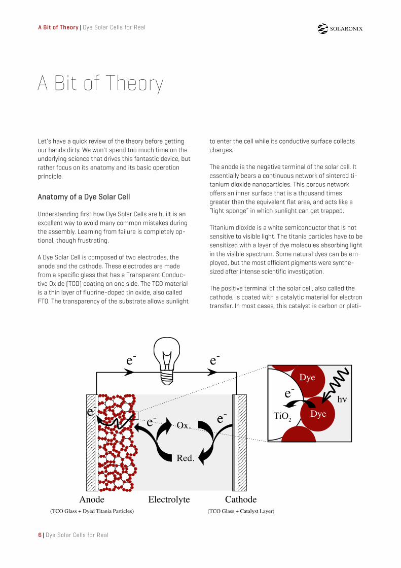
A Dye Solar Cell is composed of two electrodes, the anode and the cathode. These electrodes are made from a specific glass that has a Transparent Conduc-tive Oxide (TCO) coating on one side. The TCO material is a thin layer of fluorine-doped tin oxide, also called FTO. The transparency of the substrate allows sunlight
A Bit of Theory
to enter the cell while its conductive surface collects charges.
The anode is the negative terminal of the solar cell. It essentially bears a continuous network of sintered ti-tanium dioxide nanoparticles. This porous network o!ers an inner surface that is a thousand times greater than the equivalent flat area, and acts like a “light sponge” in which sunlight can get trapped.
Titanium dioxide is a white semiconductor that is not sensitive to visible light. The titania particles have to be sensitized with a layer of dye molecules absorbing light in the visible spectrum. Some natural dyes can be em-ployed, but the most efficient pigments were synthe-sized after intense scientific investigation.
The positive terminal of the solar cell, also called the cathode, is coated with a catalytic material for electron transfer. In most cases, this catalyst is carbon or plati-
e-
Anode Cathode
Ox.
Red.
e-
Electrolyte(TCO Glass + Catalyst Layer) (TCO Glass + Dyed Titania Particles)
e-
e-
TiO2
Dye
Dye
h!
e- e-

Dye Solar Cells for Real | A Bit of Theory
Dye Solar Cells for Real | 7
num. Since a very small quantity of catalyst is needed, the electrode remains transparent.
The space left between the two electrodes is filled with an electrolyte that ensures charge transportation through a redox couple. Iodide/tri-iodide in a nitrile solvent is typically used for this purpose.
Eventually, the two electrodes are sealed together to prevent the electrolyte solvent from evaporating. How-ever, the assembly can remain open when simplicity is preferred over durability, such as during training courses or short run tests.
We will see in this guide how to build the di!erent parts of a Dye Solar Cells in several configurations.
The Photovoltaic Magic
Now that you know what's under the hood, you proba-bly wonder how this device can produce electricity. We will reveal the magic trick of the photovoltaic e!ect happening in the solar cell.
Nature likes to keep opposite charges together so that matter appears neutral. The photovoltaic e!ect is all about violating this rule. It creates a separation of charges in the solar cell under illumination. The result-ing pairs of electrons and “holes” will strive to get to-gether again, but we will only let them do so after a short trip through an external circuit.
In a Dye Solar Cell, this charge separation happens at the interface of the titanium dioxide and the dye. Re-member that this interface is present all over the in-ternal surface of the porous layer. This allows the Dye Solar Cell to form many, many separated charges which produces an electric current, for a given solar
cell area. The structure of the Dye Solar Cell is one of the secrets of its e"cacy.
The dye molecules have the ability to absorb visible light. As they are excited by this phenomenon, the molecules will give up an electron and inject it into the adjacent titanium dioxide. The charge separation occurs when the electron is injected into the titania and the “hole” is left behind on the dye molecule.
Not surprisingly, nature hates to have these charges separated. The electron must return to the oxidized dye molecule as soon as possible. That's where kinet-ics come into play: quick wins. The fastest route back to the dye for the electron is to travel through the ex-ternal circuit. It might be a longer distance to take the highway, but it's faster than a footpath.
Injected electrons migrate through the titanium diox-ide particles and reach the TCO glass of the anode, the negative terminal of the solar cell.
When a load is connected, electrons spontaneously move to the positive terminal of the solar cell, the cathode, via the external circuit. This movement of electrons is what we call an electric current.
Thanks to the redox couple present in the electrolyte, electrons can finally be transported from the cathode's surface to the oxidized dye molecules.
Now that the charges are together again, new cycles can be performed indefinitely as long as the sun shines. This is how a Dye Solar Cell produces electricity by photovoltaic separation of charges.
That should be enough to quench your intellectual thirst for the moment. Time to practice!

Glass Preparation | Dye Solar Cells for Real
8 | Dye Solar Cells for Real
This section focuses on the preparation of the glass sub-strates for those who would like to prepare their own elec-trodes from scratch. It includes cutting the glass to the de-sired size and gives advice for cleaning prior to making any deposition.
The typical substrate for making Dye Solar Cells is a glass plate coated on one side with a Transparent and Conductive Oxide (TCO) layer. The most frequently used conductive ma-terial for that purpose is fluorine-doped tin oxide (FTO). The terms TCO or FTO glass are often used to refer to this kind of substrate.
The TCO glass plates are only conductive on one side. Make sure to clearly identify the appropriate side while making your cells. The deposition of materials discussed in this tutorial will always be performed on the conductive side.
A multimeter set to measure resistance should typically read about 10 ohms when the two probe tips are placed one milli-meter apart in the middle of the plate. This value may vary depending on the TCO glass type.
There's also an easy trick that requires no instrument. This is particularly handy for identifying which is the conductive side at any time during the assembly. Scratch each side of the glass with a plastic spatula or even your fingernail. The con-ductive side is the one that feels a little sticky. The TCO coat-ing has a rougher surface than bare glass. Visually, the coated side is also the one that looks hazy.
Identifying the Conductive Side
Glass Preparation
Parts: TCO Glass PlatesDi!erent sorts of TCO glass plates are available in standard sizes. Customized glass plates may also be supplied upon request. The typical substrates are the following.- TCO30-8, (3 mm, 8 ohm/sq FTO)- TCO22-7, (2.2 mm, 7 ohm/sq FTO)

Dye Solar Cells for Real | Glass Preparation
Dye Solar Cells for Real | 9
Attention: Glass HandlingBeware of cuts. The glass plates should be handled with care since the edges of the glass can be very sharp. Wear protective equipment such as gloves and safety glasses.
Depending on the size of your raw glass plates and the size of the solar cells you want to build, it may be necessary to cut the glass into smaller pieces. To achieve this, scribe a line on the TCO glass at the desired position using a glass knife or a cutting table. We recommend you make the scribe on the conductive side of the glass.
After the cutting line is scribed, immediately break the glass in two pieces by bending the plate from both sides of the line. Waiting too long will allow the glass to peel o! along the etch, making it much harder to break. Repeat this operation until you have the desired size of glass plates.
It is always a good idea to clean the TCO glass plates before any kind of deposition. Be sure not to use a rough scrubber that could scratch the conductive side, rather use a soft sponge dedicated to clean delicate cutlery or similar things. The choice of the detergent is also of importance. Soaps for dish washing aren't suited for cleaning TCO glass, prefer the use of a specific glass detergents like Deconex® from Borer Chemie. Such cleaning agents are designed to leave no resi-due when rinsed.
After cleaning, thoroughly rinse the glass plates with deion-ized water to prevent traces of minerals. Denatured alcohol can also be used. Use a hot-air blower for faster drying.
Cutting out Conductive Glass Plates
Cleaning Conductive Glass Plates

The Titania Electrode | Dye Solar Cells for Real
10 | Dye Solar Cells for Real
The titania electrode consists of a layer of titanium dioxide nanoparticles on a TCO glass plate. Such a layer is obtained by the deposition of a paste containing a suspension of tita-nia particles. Di!erent formulations are available and adapted to each deposition techniques.
The titanium dioxide particles must be in the size range of 10-40 nm so that the resulting sintered layer is highly po-rous. This layer, at the center of the operation principle, will ultimately act as a light-sponge in the solar cell. We use the term nanoparticles when discussing particles in that size range. Nanoparticles for the Dye Solar Cell are preferably tita-nia crystals of anatase phase, other crystalline structures can be detrimental.
The nanoparticles typically lead to a semi-transparent layer after sintering. The resulting transparency of the electrode, while o!ering design attractiveness, is not always desired. A significant fraction of light is not collected but allowed to pass through the solar cell, diminishing the conversion e"-ciency. This behavior can be circumvented with the use of bigger titania particles.
Titania particles larger than 100 nm are big enough to inter-act with light and di!use incoming beams. They are often used in the fabrication of opaque titania electrodes, either mixed with the nanoparticles, or stacked in a di!using layer. There are many types of titania pastes containing either or both nanoparticles and big particles.
It is also possible to get pre-made titania electrodes. In this case, it is recommended to run a firing process before using them. This makes sure they don’t contain moisture from am-bient air.
Parts: Titania PastesThe Ti-Nanoxide product line encompasses titania pastes formulated for di!erent depositions techniques. Several sizes of titania nanoparticles are available, including mixes with large particles.
The Titania Electrode
Parts: Ready to Use Titania ElectrodesWe can provide titania electrodes ready to use. They are prepared by screen-printing which ensures homogenous deposition and controlled thickness.- Test Cell Titania Electrode(for making high performance DSC).- Education Cell Titania Electrode(training courses and similar activities).- Demonstration Cell Titania Electrode(for making larger demonstration cells).

Dye Solar Cells for Real | The Titania Electrode
Dye Solar Cells for Real | 11
The simplest and most widely used method for depositing titania paste on a substrate is the so-called doctor-blade method. The technique is also known as slot-coating in its mechanized version. It uses a hard squeegee, or doctor-blade, to spread a portion of titania paste onto the glass. With this technique, the thickness of the titania layer is deter-mined by the thickness of a spacer placed on both sides. We recommend using the "Scotch Magic #810" tape from 3M, which has a thickness of about 50 #m. This tape can be easily removed from the glass without leaving traces of glue.
With the conductive side facing up, apply two parallel strips of tape on the edges of the glass plate, covering about 5 to 7 mm of glass. The area of uncovered glass in the middle of the glass is where the titania will be deposited. Edges masked by the tape will give room for future sealing and electrical con-tacts. Take advantage of the adhesive tape to hold the glass plate in position on the workbench. This will prevent the plate from moving while making the deposition stroke.
Settling of the titania paste can occur over time. Make sure to start with a homogenous paste, stir well before use with a glass rod or similar tool. Don't shake the bottle, this can cre-ate air bubbles and prevent a good deposition.
Preparing the Substrate for Deposition
Attention: The Right SideThe TCO glass plates are only conductive on one side. Make sure to clearly identify the appropriate side while making the assembly of your cells. Deposition must be performed on the conductive side.
Getting the Paste Ready

The Titania Electrode | Dye Solar Cells for Real
12 | Dye Solar Cells for Real
Apply a portion of paste near the top edge of the TCO glass between the two pieces of tape. With a rigid squeegee, such as a microscope slide or a glass rod, spread the paste across the plate with the support of the adhesive tapes on both sides. The gap between the strips of tape should be filled with a layer of titania paste. Repeat the operation until you have a reasonably homogenous layer.
This deposition technique can also be used to obtain a slightly thicker titania layer. This can be desirable for increas-ing the electrical output of the resulting solar cell. Following the same method, stacking two layers of adhesive tape will make a thicker spacer for spreading the paste. Please note however that having a thicker titania layer also makes it more delicate to treat as it may crack during firing. Start practicing with thin layers.
There are other deposition methods, such as spin-coating and screen-printing which require the corresponding ma-chinery and adapted titania paste formulations. This tutorial will not discuss these topics, assuming the experimenter will-ing to make titania electrodes with either of these advanced techniques is knowledgeable about the required processes.
Parts: Doctor-Blade Titania PastesFormulations of anatase titania nanoparticles are available for the doctor-blading technique. The pastes are available in di!erent particle sizes, depending on the desired transparency of the titania electrode.- Ti-Nanoxide D, opaque electrode.- Ti-Nanoxide T, transparent electrode.- Ti-Nanoxide HT, highly transparent electrode.
Doctor-Blading the Titania Paste

Dye Solar Cells for Real | The Titania Electrode
Dye Solar Cells for Real | 13
Attention: Glass BreakGlass plates are sensitive to sudden changes in temperature. Make sure to warm up and cool down your samples at reasonable speed (50°C per minute for instance). Rapid temperature changes can cause the plates to break.
The titania electrode is completed by firing the deposited layer. The vehicle of the paste burns away, leaving the titania nanoparticles sintered together. This process ensures electri-cal contact between particles and good adhesion to the TCO glass substrate.
Sintering can occur in an oven, or on a programmable hot-plate. First remove any adhesive tapes used for doctor-blade deposition, and place the freshly coated glass plate in or on the heating device at room temperature. Set the desired temperature to 450°C. While heating up, you may observe that the titania layer turns brown/yellow and releases fumes. This corresponds to the evaporation and combustion of the non-toxic chemicals used in the paste formulation. After 15 to 20 minutes at 450°C, the baked titania layer looks white again or transparent, indicating that the sintering process is over.
Allow the heating device to cool down before removing the fired electrode. A sudden change in temperature can cause the glass to break. The resulting nanoporous layer made from the sintered particles can absorb moisture from ambient air, make sure to store the sintered electrodes in a sealed envi-ronment soon after firing.
Sintering the Titania Layer

The Titania Electrode | Dye Solar Cells for Real
14 | Dye Solar Cells for Real
The sintered titania electrode has a band of titanium dioxide in the middle, with room for connection on two ends. It might also be useful to make room on the two other edges for laying a sealing gasket. Scratch away the excess of material on the other two ends with a non-metallic tool. The titania area should then be confined to the middle of the glass plate.
The electricity produced by the finished solar cell is collected from the edges of the glass electrodes. Therefore, it is neces-sary to have enough space for the electrical contacts, could they be clips or wires.
Remember that titania electrodes might take up water and other pollutants from air when stored for a long period. It is best to use the electrode right away.
If you are starting with an existing fired titania electrode, it is strongly recommended that you re-fire the electrode. This ensures that no pollutants are left on the titania surface prior to solar cell assembly. Re-firing is done by simply repeating the firing procedure discussed above.
Making Room for Contacts and Sealing
Attention: Non-Metallic ToolPreferably use a non-metallic tool for scratching titania o! the TCO glass. A metallic spatula can leave bits of metal that may eventually pollute the solar cell.
Re-firing a Titania Electrode

Dye Solar Cells for Real | Staining the Titania
Dye Solar Cells for Real | 15
Hint: Frozen BerriesFrozen berries are a good source of natural dye and can be conveniently stored until the moment of the experiments.
Titanium dioxide is a white semiconductor that doesn’t ab-sorb visible light. Therefore, it is necessary to color, or sensi-tize, the titania electrode with a dye that can absorb as much light as possible in the visible light spectrum. This section discusses the di!erent methods for staining a titania elec-trode with a sensitizing dye.
Staining With a Natural Dye
Staining the Titania
Green plants and their fruits are a fantastic source of natural dyes that absorb visible light. The red pigments found in raspberries or blackberries can work especially well in Dye Solar Cells. Red fruits are very handy for experimenting in training courses where the use of synthetic dyes can be an issue.
The sensitization of titanium dioxide by natural dyes consists of soaking the titania electrode in mashed fruits. Complete staining can take from several minutes to several hours, while the dye molecules from the fruit juice naturally adsorb onto the titania particles. The longer the electrode soaks in the dye, the better dyed the titania will be.
Start crushing fresh red fruits in a petri dish or similar con-tainer. The fruits must be juicy enough to get the titania elec-trode completely soaked.

Staining the Titania | Dye Solar Cells for Real
16 | Dye Solar Cells for Real
Place the fired electrode onto the mashed fruits with the tita-nia surface facing down. If necessary, apply slight pressure on the glass plate so that the whole titania area is soaked by the mixture.
Close the container and wait for the staining to complete. The sensitization process takes an hour or more. Wait as long as possible, so that more dye molecules can attach to the tita-nia.
Remove the stained electrode and rinse it carefully with etha-nol. Wait a few minutes for the ethanol to evaporate or use a hair-dryer to gently dry the electrode faster.
The resulting stained titania should now look red almost all over its surface. If not, put it back in the fruit juice for further dyeing.
Note that the mashed fruits don't o!er a homogenous me-dium, and may cause a pattern on the stained titania elec-trode. This is not a problem with the operation of the solar cell.

Dye Solar Cells for Real | Staining the Titania
Dye Solar Cells for Real | 17
Attention: Dye HandlingDo not breath dust of dye and avoid ingesting the sensitizer. Synthetic dyes aren’t fully tested substances.
The staining procedure can also be realized by soaking the sintered titania electrode in a synthetic dye solution.
The dye molecules will naturally adsorb onto the titania nano-particles and won't be desorbed by rinsing. The synthetic dyes developed for the Dye Solar Cells contain anchoring groups that have a natural a"nity for titanium dioxide surfaces.
Furthermore, these molecules are optimized for light collec-tion and thus demonstrate better performances than natural dyes. We recommend using one of the most cited dyes in the scientific literature, typically the ruthenium sensitizer Ruthenizer 535-bisTBA (also known as N719).
Staining With a Synthetic Dye
Parts: Synthetic DyesHere are some synthetic dyes demonstrating very good sensitization of titania electrodes. They o!er an enjoyable color palette that helps in making visually appealing solar cells. - Ruthenizer 535-bisTBA, purple- Ruthenizer 620-1H3TBA, dark green- Sensidizer SQ2, vivid green
Preparing a dye solution:
First prepare a dye solution for the staining bath. Make sure the volume is adapted to completely immerse your titania electrode.
A typical concentration is around 3 x 10⁻⁴ M in methanol or ethanol. For instance, dissolve about 10 mg of dry dye powder in 25 mL of methanol and stir until no traces of solid are visi-ble. This might take up to several hours at room temperature, depending on the concentration and size of the powder gran-ules. The solution usually becomes deeply colored very quickly whereas only a small amount of the dye has actually dis-solved. Most of the solid takes longer to dissolve but does not o!er a drastic visual change.
The staining solution can be prepared in advance and can be used for several experiments. However, the dye solution can be notably degraded by water and light. The dye gets oxidized and the solution changes in color. Keep the dye solution away from light and moisture in a sealed bottle. Preferably prepare small volumes each time and store dry material long term.

Staining the Titania | Dye Solar Cells for Real
18 | Dye Solar Cells for Real
Once your dye solution is ready, place the required amount of liquid in a staining bath vessel that can be kept tightly closed.
Slowly immerse the sintered titania electrode in the staining bath. The titania layer should be facing up, so that it doesn't get scratched by friction on the bottom of the vessel.
Remove the electrode from the bath and carefully rinse the stained titania with ethanol.
Close the container and wait for the staining to complete. The sensitization process typically takes 4 to 8 hours at room temperature, depending on the titania layer thickness and concentration of the dye solution. Staining can be acceler-ated by increasing the dye solution concentration if neces-sary.
Several electrodes can be stained at a time in the same ves-sel. The amount of dye present in the solution is much greater than what adsorb on the titania.
Attention: Away From Water and LightNo water should enter the sensitizing solution (air moisture is not critical). Keep the dye solution away from light.

Dye Solar Cells for Real | Staining the Titania
Dye Solar Cells for Real | 19
A properly sensitized electrode doesn't show any white area, especially when looking at the stained titania through the glass on the rear side.
For example, the absorbed dye should look deep red to purple whenever Ruthenizer 535-bisTBA is employed. If it looks brown instead, the dye has been oxidized and won't operate well in the solar cell.
While rinsing, it is recommended that you do not mix the rinsing waste with the staining solution. The staining solution may be reused in future experiments.
The stained electrode can dry on its own, or you can use a hair-dryer to evaporate the rinsing ethanol faster. The freshly stained electrodes are meant to be used immediately, it is not advised to store them dry before assembly. Better leave the electrode in the dye solution until it can be assem-bled.
Titania electrodes prepared during a previous session, or pur-chased as is, can be re-fired so that the titania layer is free of moisture or other contaminants that might have entered dur-ing storage.
If the titania electrode is prepared during the same session, remove the electrode from the heating device when the tem-perature is around 60°C and immerse it immediately in the staining solution. This greatly reduces the chance the elec-trode will adsorb any ambient moisture.
Hint: Storing Dye SolutionsStore your dye solution away from light and moisture to use it for other experiments. If you are going to store the dye for a long time (i.e. months or longer), evaporate the solvent and dry the solid dye completely before storing away from light and moisture.

The Platinum Electrode | Dye Solar Cells for Real
20 | Dye Solar Cells for Real
The previous chapter described the making of anodes from sintered titania particles. The Dye Solar Cell also requires a cathode to complete the assembly.
The titania anode is where charge separation, the magic of the photovoltaic e!ect, occurs. We often call the titania an-ode the working-electrode. The cathode is frequently referred as the counter-electrode.
This section and the following one details the fabrication of platinum and carbon counter-electrodes. Either one can be used as a cathode to make a Dye Solar Cell, however it is not necessary to make both of them. The carbon electrode is easier and cheaper to make, but we will focus first on the platinum electrode which gives the best performance.
Platinum is known for its strong catalytic activity in electron transfer at the counter-electrode. An e"cient cathode for a Dye Solar Cell can consist of a thin platinum layer on a TCO substrate. This is obtained by the deposition of a platinum precursor by either painting with a brush, doctor-blading, or screen-printing. There are formulations of platinum precur-sors for these di!erent deposition techniques.
It is also possible to get pre-made platinum electrodes. In this case, it is strongly recommended to run a firing process at 450°C before using them in order to reactivate the cata-lytic platinum layer. This process is detailed below.
Parts: Ready to Use Platinum ElectrodesWe can provide you platinum electrodes ready to use. They are prepared by screen-printing which ensures homogenous layer.- Test Cell Platinum Electrode(for the making of high performance DSC).- Education Cell Platinum Electrode(training courses and similar activities).- Demonstration Cell Platinum Electrode(for making larger demonstration cells).
The Platinum Electrode

Dye Solar Cells for Real | The Platinum Electrode
Dye Solar Cells for Real | 21
Attention: Light Sensitive ProductThe platinum precursor paint is light-sensitive. Make sure to store it away from light and fire freshly painted electrodes rapidly.
Start with a TCO glass plate matching the size of the titania electrode being used. Gently paint the platinum precursor ink onto the conductive side of the TCO substrate with a regular brush. The catalytic layer of platinum will be active after firing the painted TCO glass.
Firing should be completed soon after painting since the platinum precursor can su!er from light exposure. Skip to the firing section below to learn how to finish your platinum elec-trode.
Brush-Painting the Platinum Precursor
Parts: Platinum Precursor PaintPlatisol T is a liquid solution of platinum precursor that can be applied with a paintbrush.
The platinum precursor can also be applied by doctor-blading from a viscous paste such as a formulation for screen-printing. Start with a TCO glass plate matching the size of the titania electrode being used.
This method is similar to the doctor-blading of titania paste described earlier. With the conductive side facing up, apply two parallel strips of adhesive tape on the edges of the glass plate, covering about 5 to 7 mm of glass. Take advantage of the adhesive tape to hold the glass plate in position on the workbench. This will prevent the plate from moving while making the deposition movement.
Doctor-Blading the Platinum Precursor

The Platinum Electrode | Dye Solar Cells for Real
22 | Dye Solar Cells for Real
Apply a portion of platinum precursor paste near the top edge of the TCO glass between the two pieces of tape.
With a rigid squeegee, such as a microscope slide or a glass rod, spread the paste down the plate with the support of the adhesives tape on either side.
Remove the adhesive tapes. The gap between the stripes of tape should be filled with a layer of platinum precursor paste.
The catalytic layer of platinum is obtained after firing. The platinum precursor will turn into metallic platinum at elevated temperature. It is important to proceed with firing quickly since the platinum precursor can degrade in light.
Parts: Platinum Precursor PastePlatisol T/SP is a formulation of platinum precursor for screen-printing that can be also applied by doctor-blading.
Attention: Light Sensitive ProductThe platinum precursor paste is light-sensitive. Make sure to store it away from light and fire treated electrodes rapidly after deposition.

Dye Solar Cells for Real | The Platinum Electrode
Dye Solar Cells for Real | 23
With either deposition technique, a firing process is neces-sary to activate the platinum layer.
Put the glass plate with freshly deposited platinum precursor in or on the heating device at room temperature. Set the de-sired temperature to 450°C and maintain the electrode at this temperature for at least 10 minutes. The activated plati-num layer forms during this time.
Allow the glass plate to cool down and remove it from the heating device. A sudden change in temperature can cause the glass to break.
This step can also be used to reactivate a platinum electrode that was prepared in a previous session or purchased.
Platinum electrodes can be stored away from air and light for future use but will require re-firing prior to assembly.
The resulting electrode features a nearly invisible layer of platinum. Its catalytic activity can be tested before continuing the assembly.
Place a drop of hydrogen peroxide on the electrode (a 30% solution in water su"ces). Bubbles should evolve from the platinum surface within the drop, indicating the active plati-num layer formed properly.
Clean with deionized water and ethanol to remove any trace of hydrogen peroxide prior usage of the platinum electrode.
Firing the Platinum Electrode
Testing the Catalytic Activity
Attention: Glass BreakGlass plates are sensitive to sudden changes in temperature. Make sure to warm up and cool down your samples at reasonable speed (50°C per minute for instance). A too rapid temperature change can cause the plates to break.

The Carbon Alternative | Dye Solar Cells for Real
24 | Dye Solar Cells for Real
The cathode of a Dye Solar Cell is frequently made with plati-num, but carbon also demonstrates interesting catalytic ac-tivity. The carbon alternative, although being less e"cient than its platinum counter part, is easier and cheaper to real-ize. This makes carbon electrodes of great interest for educa-tional purposes. Two practical ways of making such a carbon counter-electrode are described here.
Pencils can be a convenient source of carbon that’s very easy to apply. Start with a TCO glass plate matching the size of the titania electrode being used for the assembly.
Cover the entire conductive surface with the pencil. A discrete layer of carbon is now attached to the glass. It is not neces-sary to have more material on the cathode. Your electrode is ready to go, no need for firing.
From a Pencil
The Carbon Alternative

Dye Solar Cells for Real | The Carbon Alternative
Dye Solar Cells for Real | 25
Attention: Hot GlassDuring this procedure, the glass plate may become hot and cause burns. Use a pair of tweezers for handling the glass safely.
Another way to obtain a carbon electrode is through the deposition of soot from a burning candle. Start with a TCO glass plate matching the size of the titania electrode being used for the assembly.
Light a candle and hold the piece of TCO glass, conductive side facing down, about 10 cm above the flame. The carbon from the combustion of wax is carried in the smoke and makes a black deposition on the conductive side of the TCO glass.
The process is very fast, so don't over do it. A homogeneous gray to black layer is enough.
Allow the glass plate to cool on a suitable surface before fur-ther processing.
From a Candle

Putting Electrodes Together | Dye Solar Cells for Real
26 | Dye Solar Cells for Real
We have seen how to prepare a titania anode and a counter-electrode made from either platinum or carbon. Now let's see how to assemble the two electrodes into a solar cell.
When the electrodes are put together, the active sides of the anode and the cathode will be facing each other. In other words, the stained titania will face the platinum or carbon of the counter-electrode. The gap left between the two glass plates will be filled with electrolyte during the next step.
This step can be accomplished using two di!erent ap-proaches. First, electrodes can be pressed together, and the electrolyte soaked in the resulting stack by capillary e!ect. Second, the two electrodes can be sealed together and the electrolyte injected via holes drilled through the cathode.
The first approach is called an “open cell” because the inner part of the solar cell is exposed to air. This is a very easy setup, but the electrolyte won't be confined in the cell and will eventually dry out. Such an assembly is practical for training courses, where results must be obtained quickly. However, the resulting solar cells won't last as long as in a sealed configu-ration.
The second approach is meant to give longer lasting solar cells. The electrodes are sealed together with a gasket so that the electrolyte is confined in the cavity. It certainly takes more e!ort to manufacture, but it allows the Dye Solar Cells to op-erate for an undetermined period of time.
Depending on your goals, speed or durability, follow the in-structions for the open cell or sealed cell configurations.
Putting Electrodes Together
Dye Solar Cells for Real | Putting Electrodes Together
Dye Solar Cells for Real | 27
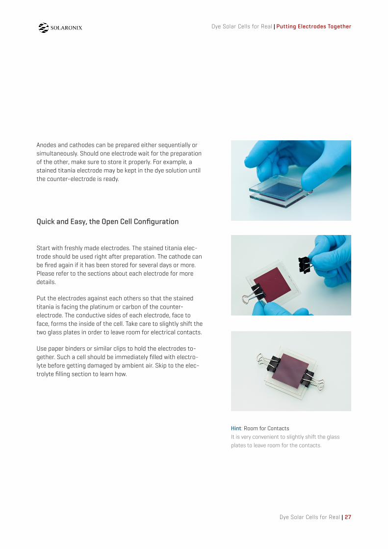
Start with freshly made electrodes. The stained titania elec-trode should be used right after preparation. The cathode can be fired again if it has been stored for several days or more. Please refer to the sections about each electrode for more details.
Put the electrodes against each others so that the stained titania is facing the platinum or carbon of the counter-electrode. The conductive sides of each electrode, face to face, forms the inside of the cell. Take care to slightly shift the two glass plates in order to leave room for electrical contacts.
Use paper binders or similar clips to hold the electrodes to-gether. Such a cell should be immediately filled with electro-lyte before getting damaged by ambient air. Skip to the elec-trolyte filling section to learn how.
Quick and Easy, the Open Cell Configuration
Anodes and cathodes can be prepared either sequentially or simultaneously. Should one electrode wait for the preparation of the other, make sure to store it properly. For example, a stained titania electrode may be kept in the dye solution until the counter-electrode is ready.
Hint: Room for ContactsIt is very convenient to slightly shift the glass plates to leave room for the contacts.

Putting Electrodes Together | Dye Solar Cells for Real
28 | Dye Solar Cells for Real
Preparing for the Sealed Cell Configuration
Parts: Drilled ElectrodesPlatinum electrodes can be ordered pre-drilled for electrolyte filling.- Test Cell Platinum Electrode (drilled)(for the making of high performance DSC).- Education Cell Platinum Electrode, drilled (training courses and similar activities).- Demonstration Cell Platinum Electrode, drilled (for making lager demonstration cells).
In the sealed configuration, electrodes are put together with the help of a hot-melt gasket around the titania area. The cavity left by the sealing material between the two glass plates ensures a confinement of the electrolyte in the solar cell. With this approach, it is necessary to drill holes through the cathode that will be used for filling the cell with electro-lyte during the next assembly step.
Drilling the cathode:
Drill two holes through the counter-electrode with a drill bit appropriate for glass. Typical carbide drill bit diameters are either 1.0 or 0.5 mm.
Position the two holes on opposite corners of the cell, and make sure they fit in the inner dimensions of the gasket. Electrolyte will be flushed from one end to the other.
For a cleaner hole, drill half way through the glass from both sides. This will prevent the glass from chipping, which can occur when the hole is drilled completely through from one side.
Drilling the glass is a delicate step and you may prefer to per-form so on a bare TCO glass before any deposition. Beware that drilling too close to the edge of the glass can cause breakage.
TCO glass plates and platinum electrodes can be purchased with pre-drilled holes in order to avoid this difficult step.
Dye Solar Cells for Real | Putting Electrodes Together
Dye Solar Cells for Real | 29
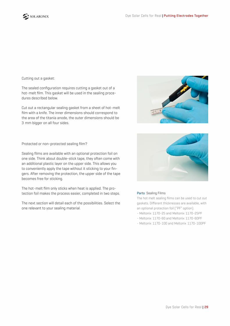
Parts: Sealing FilmsThe hot melt sealing films can be used to cut out gaskets. Di!erent thicknesses are available, with an optional protection foil (“PF” option).- Meltonix 1170-25 and Meltonix 1170-25PF- Meltonix 1170-60 and Meltonix 1170-60PF- Meltonix 1170-100 and Meltonix 1170-100PF
Cutting out a gasket:
The sealed configuration requires cutting a gasket out of a hot-melt film. This gasket will be used in the sealing proce-dures described below.
Cut out a rectangular sealing gasket from a sheet of hot-melt film with a knife. The inner dimensions should correspond to the area of the titania anode, the outer dimensions should be 3 mm bigger on all four sides.
Protected or non-protected sealing film?
Sealing films are available with an optional protection foil on one side. Think about double-stick tape, they often come with an additional plastic layer on the upper side. This allows you to conveniently apply the tape without it sticking to your fin-gers. After removing the protection, the upper side of the tape becomes free for sticking.
The hot-melt film only sticks when heat is applied. The pro-tection foil makes the process easier, completed in two steps.
The next section will detail each of the possibilities. Select the one relevant to your sealing material.

Putting Electrodes Together | Dye Solar Cells for Real
30 | Dye Solar Cells for Real
Sealing Without a Protection Foil
Start with freshly made electrodes. The stained titania elec-trode should be used right after preparation. The cathode can be fired again if it has been stored for several days or more. Please refer to the sections about each electrode for more details.
Carefully place the gasket around the titania area on the an-ode. The dimensions of the gasket and the stained titania shall match but not overlap. There should be one edge of the electrode that's not completely covered by the gasket to leave room for electrical contacts.
With a soldering iron, and covering the gasket with a non-stick temperature resistant film such as a PTFE or PET foil, melt a spot of material in each corner so that the gasket slightly adheres to the glass. This optional step can help to hold the gasket in place prior to sealing.
Place the counter-electrode, conductive side facing down, on top of the gasket. This stack keeps the sealing material in place between the electrodes. If necessary, shift the two glass plates in order to leave room for the the electrical con-nections on both glass plates.
Parts: Pre-cut GasketsThe gaskets in the dimensions for pre-made electrodes are available.- Test Cell Gaskets (for the making of high performance DSC).- Education Cell Gaskets (training courses and similar activities).- Demonstration Cell Gaskets (for making larger demonstration cells).

Dye Solar Cells for Real | Putting Electrodes Together
Dye Solar Cells for Real | 31
Hint: From Protected to Non-ProtectedThe protective foil can be removed prior to use in order to transform a protected sealing film into its non-protected version. Put a piece of adhesive tape on a corner of each side of the sealing film. Then pull away the two tapes apart so that the protective foil is detached from the sealing film.
Apply heat and pressure all over the gasket with the help of a hot press or a similar tool set at about 110°C. After a few tens of seconds, the hot melt material should glue the electrodes together. If not, repeat this operation until the whole surface of the gasket has melted onto both electrodes.
A good adhesion of the sealing film to the glass plates can be confirmed by a careful visual examination. The hot-melt ma-terial should match the refractive index of the glass and look completely transparent all over the gasket surface.
The degradation of finished Dye Solar Cells is almost always due to leaks from imperfect sealing. Temperature and pres-sure adjustments might be necessary to find the optimal conditions for your setup.
Remember that the stained titania electrode is sensitive to air and light exposure. Even if the electrodes are now sealed, air can still get in the cell because of the holes in the cathode. Proceed directly to electrolyte filling.

Putting Electrodes Together | Dye Solar Cells for Real
32 | Dye Solar Cells for Real
Sealing films can be purchased with a protection foil to facili-tate the sealing process. This protection consists of a second plastic film sandwiched together with the sealing material. The protection foil won't melt on the electrodes and won't adhere to the sealing material or glass.
The whole sealing process can be done more comfortably in two steps instead of one. First, melt the gasket onto one electrode. Then peel o! the protection with a pair of sharp tweezers. Finally melt the other side of the gasket onto the second electrode. Find out how below.
Sealing With a Protection Foil
Hint: Recognize the Protected SideThe protected side has a more glossy aspect and slides easier under one's fingernail.
Step 1:
Place the gasket on the conducting side of the cathode so that it fits with the edges of the glass plate, with the protec-tion foil facing up. There should be one edge of the electrode that's not covered by the gasket to leave room for electrical contacts.
With the help of a soldering iron, melt a spot of material in each corner so that the gasket slightly adheres to the glass. This optional step can help to hold the gasket in place prior sealing.
Apply heat and pressure all over the gasket surface with the help of a hot press or a similar tool set at 110°C. A domestic iron set to synthetic fabric can be advantageously turned into a hot press.
After few seconds, the hot-melt material should have stuck to the electrode. If necessary, put an additional PTFE or PET film on top of the gasket to prevent accidental adhesion to the hot surface. Repeat this operation until the whole surface of the gasket has melted onto the substrate.
Be careful not to apply too much pressure. This can cause the gasket to spread out, resulting in uneven gasket thick-ness.

Dye Solar Cells for Real | Putting Electrodes Together
Dye Solar Cells for Real | 33
Step 2:
Thanks to the protection foil, the top side of the sealing ma-terial didn't adhere to the hot press. Once cooled down, peel o! the protection foil with a knife or a pair of sharp tweezers. The other side of the sealing material is now exposed and ready for a second sealing step. Just like double-stick tape.
Place the titania electrode, conductive side facing down, on top of the gasket and align it with the area of stained titania. The resulting stack of electrodes is ready for the second step of the sealing. The two glass plates should be slightly shifted to leave room for electrical connections.
Apply heat and pressure all over the gasket surface with the help of a hot press or a similar tool set at 110°C. After few a tens of seconds, the hot-melt material should glue the elec-trodes together. If not, repeat this operation until the whole surface of the gasket has melted onto both electrodes.
A good adhesion of the sealing film to the glass plates can be confirmed by a careful visual examination. The hot-melt ma-terial should match the refractive index of the glass and look very transparent all over the gasket surface.
The degradation of finished Dye Solar Cell is almost always due to leaks from imperfect sealing. Temperature and pres-sure adjustments might be necessary to find the optimal conditions for your setup.
Remember that the stained titania electrode is sensitive to air and light exposure. Even if the electrodes are now sealed, air can still get in the cell because of the holes in the cathode. Proceed directly to electrolyte filling.
Hint: Seal Holes for Delayed FillingUse small pads of sealing film to temporarily seal the filling holes. This protects the stained titania from air and allows storage of the electrodes in the dark. Once you are ready for filling with electrolyte, simply peel o! the pads with a knife.

Filling With Electrolyte | Dye Solar Cells for Real
34 | Dye Solar Cells for Real
The gap between the two electrodes can now be filled with electrolyte to complete the Dye Solar Cell. This is performed either by capillary e!ect in open cells, or by injection through the filling holes in sealed cells.
It is best to fill the cells with electrolyte as soon as the elec-trodes are put together. The stained titania will otherwise be exposed to air for too long and possibly degrade.
Filling With Electrolyte
The electrodes have been put together and held with binders, immediately start filling with electrolyte before air and mois-ture degrades the electrodes.
Place a few drops of electrolyte at the interface of the two glass plates with a pipette, and allow the liquid to be drawn into the cell by capillary e!ect. If necessary, repeat this op-eration until the entire internal surface of the solar cell is wetted with electrolyte.
Wipe off any excess liquid with a paper towel and manipu-late the cell carefully to avoid skin contact with the electro-lyte.
The Dye Solar Cell is now operational and will last until the electrolyte solvent evaporates.
Since the assembly is open to ambient air, the performance of the cell will decrease over time. This assembly however will give plenty of time to measure and demonstrate the electrical output of the photovoltaic device.
Filling an Open Cell
Parts: Low Volatile ElectrolyteOpen cells are most often prepared during training courses, it is preferable to employ a low volatile electrolyte in such conditions. We have a formulation named Education Electrolyte for that purpose.

Dye Solar Cells for Real | Filling With Electrolyte
Dye Solar Cells for Real | 35
Parts: High Performance Iodide ElectrolytesWe recommended one of the following electrolytes.- Iodolyte AN-50, for best quick performance(50 mM iodide/tri-iodide in acetonitrile)- Iodolyte Z-50, for long term stability(50 mM iodide/tri-iodide in methoxypropionitrile)
The cavity formed by the sealing gasket between the two sealed electrodes must be now filled with electrolyte. Beware that the holes drilled through the counter-electrode expose both electrodes to ambient air. Proceed directly to electrolyte filling before the electrodes are damaged by air and moisture.
Use a syringe to flush the electrolyte from one hole, through the cell, to the other hole. A small joint cut out of a silicon tube can be placed on the tip of the syringe to prevent leaks.
Complete filling can be confirmed by a visual examination. A few small bubbles remaining in the solar cell are not detri-mental to proper operation. Just make sure to get most of the cavity filled.
Wipe o! any excess electrolyte left around the filling holes and clean the glass with an acetone wetted paper towel. Any electrolyte left on the glass could hinder proper sealing of the filling holes in the next step.
Filling a Sealed Cell

Filling With Electrolyte | Dye Solar Cells for Real
36 | Dye Solar Cells for Real
The two holes used for filling must now be closed to complete the sealed assembly. For this purpose, a small glass cap will be sealed on top of each hole with another piece of sealing film.
It is very important that no electrolyte remains on or around the filling holes. This will prevent adhesion of the sealing ma-terial.
Repeat the operation described previously for sealing the electrodes together, but with small glass caps and the corre-sponding pieces of sealing film.
Proceed in either one or two steps, depending on whether the sealing film comes with a protective foil or not. Apply heat and pressure on both seals with the help of a hot press or a similar tool set at 110°C. After a few seconds, the hot-melt material will seal the holes for good.
The resulting Dye Solar Cell is now ready for use. The sealed configuration ensures the confinement of electrolyte in the cell and prevents moisture from entering. A sealed Dye So-lar Cell can operate for an undetermined period of time when assembled correctly.
Sealing the Filling Holes
Parts: Glass Caps and Sealing PadsIt is possible to get pre-cut glass caps and sealing pads. These tiny bits of materials can save you a lot of time.

Dye Solar Cells for Real | Filling With Electrolyte
Dye Solar Cells for Real | 37
Advanced experimenters may like to enhance current collec-tion on the electrodes. Charge transport on the conductive glass is impaired by the resistivity of the FTO coating. This e!ect can be reduced at the edges of the electrodes by ap-plying a more conductive material.
The space left for contacts on both electrodes can be care-fully painted with silver paint. The increased conductivity of this paint allows better flow of electricity generated in the solar cell. Beware that the paint must not form a short-circuit between the two electrodes.
Conductive adhesive tapes can also be placed on the glass edges to obtain the same enhancement. It is also possible to solder a layer of tin on the TCO surface but this requires an ultrasonic soldering iron.
A Final Touch

Testing the Solar Cell | Dye Solar Cells for Real
38 | Dye Solar Cells for Real
Whether your cell is in the open or sealed configuration, it is now ready for operation. If you are like us, your excitement for making solar cells is now at its zenith! Time to give it a try!
Connect a voltmeter, negative end to the anode (titania elec-trode) and positive end to the counter-electrode. Measure the open circuit voltage under full sun illumination. It should be around 0.6 V.
Note that the cell output can vary drastically upon the nature of the light source as they don't o!er the same spectral qual-ity. Prefer incandescent or halogen lamps to fluorescent bulbs.
Similarly, an ammeter allows for the measurement of the short circuit current of the solar cell. This value can vary greatly, depending on geometry of the cell and light condi-tions, as well as other internal parameters, such as titania layer thickness and electrolyte composition. You may observe that your cells get better after a wear in period under illumi-nation.
Provided size and illumination are great enough, your cell may be able to power a small electric load such as a low current motor.
Parts: Electric LoadsDye Solar Cells of a few square centimeters provide enough current to spin a low current motor. You might enjoy one of these accessories for your solar cells:- Low Current Motor.- Model Wind Turbine.
Testing the Solar Cell

Special thanks to our Solaronix fellows who contributed to the writing of this guide, Frédéric Oswald for the help in making pictures, and Michael Scott for his valuable input.
Thanks to all the readers whose comments helped in getting this document better.
Thank You
Dye Solar Cells for Real is published under the Creative Com-mons Attribution Non-Commercial Share Alike license. http://creativecommons.org/licenses/by-nc-sa/3.0/
We wanted this work to be open for people to use it as an in-put for their own documents. You are therefore free to copy, distribute, and adapt this work, under the following condi-tions: You have to attribute Solaronix and the author, and you must not use this work for commercial purposes. If you mod-ify or build upon this work, you need to share your work with the same license, so that the entire community can benefit from the derivatives.
We hope this guide will help you to make Dye Solars Cells. Your feedback is greatly appreciated, feel free to send your comments and suggestions to David Martineau ([email protected]). We look forward to hearing from you.
Get Involved
Solaronix SA
www.solaronix.com
Rue de l’Ouriette 129CH-1170 AubonneSwitzerland
T +41 21 821 22 80F +41 21 821 22 [email protected]
Lausanne
France
Switzwerland
France Switzwerland
Geneva
Geneva Airport
Aubonne