dye penetrant indications caused by superficial surface...
TRANSCRIPT

Dye Penetrant Indications Caused by Superficial Surface Defects in 2014 Aluminum Alloy Welds
Many dye penetrant indications are superficial (less than 0.007 in. deep) and can be eliminated or minimized sufficiently that real weld defects can be identified.
BY Ft. G. H O C K E R A N D K. R. W I L S O N
ABSTRACT. Dye penetrant indications on the heat-affected zone of 2014-T6 aluminum weldments have caused many rejections of production assemblies. An investigation of this problem has revealed that a large majority of these indicated defects were superficial in that they were less than 0.007 in. deep.
Tests were conducted to determine the cause and nature of the surface defects. Procedures were developed to eliminate or minimize the occurrence of dye penetrant indications, and to discriminate between real weld defects and superficial surface defects. Also, procedures were developed for repairing weldments containing dye penetrant indications.
Macroscopic and microscopic evaluations identified the following four types of superficial surface defects which caused dye penetrant indications: grain boundary melting and cracking, weld spatter, local arc-plasma inpingement (cast puddles in the surface of the heat-affected zone) and grain boundaries which had been attacked by the caustic etch used in the dye penetrant inspection procedure. Methods for minimizing these superficial defects include (1) stabilization of the arc, (2) utilization of direct current "GTA" weld procedures, (3) reduction of caustic etch time and (4) utilization of fine grain material.
Introduction
The occurrence of dye penetrant indications on the weld heat-affected zone of GMA (gas metal-arc) welded 2014-T6 aluminum has caused many rejections of production assemblies. Many of the dye penetrant indications were linear and ranged from 1/a 2-in. to approximately V2-in. in length. These indications occurred on the surface of the weld heat-affected zone of both extrusion and sheet weldments,
R. G. HOCKER and K. R. WILSON are with the Materials and Methods—Research and Engineering Douglas Missile & Space Systems Division, McDonnell Douglas, Corp., Santa Monica, California.
but only on the crown side. They also occurred in the heat affected zone, within Vjg-in. of the fusion line, on surfaces which had been machined after welding. The preponderance of indications occurred on weldments made with large grain extrusions.
An investigation was conducted to identify the nature of the surface defects which were being detected on production parts and duplicate them in the laboratory. Procedures were then developed to minimize their occurrence and remove them from weldment surfaces.
Procedure
Weldments containing surface defects similar to those observed on production parts were made to provide samples for metallographic analysis. These weldments were made with 2014-T6 aluminum "Y" shaped extrusions and 2014-T6 aluminum sheet in two thicknesses, 0.250 and 0.105 in. Extrusions having three different grain sizes with average diameters of 0.01, 0.12, and 0.25 in., were used in this investigation. The following current production weld parameters were selected for single and multi-pass GMA welding:
4043 filler wire—3/64-in. diameter
Shielding gas flow—60 cu ft per hr
Welding speed—28 in. per min Arc current—135-145 amp range;
direct current reverse polarity (dcrp)
Arc voltage—22 to 26v Torch angle—10 deg forward tilt Back-up bar—titanium
Two types of shielding gas were used, argon and argon with 0 .1% oxygen. After welding, dye penetrant inspection was performed using the following procedure: (1) Contrast
dye penetrant (MIL-1-25135, Group 1) was brushed on the surface and allowed to stand a minimum of 5 minutes; (2) the dye was wiped off with a damp cloth and a light, even coat of dye penetrant developer (MIL-1-25136, Group 1) was sprayed on the surface.
Some weldments had approximately 0.090 in. machined off the surface prior to penetrant inspection. Weld surfaces which were machined were dye penetrant inspected with and without prior caustic etching. A caustic etch removed smeared metal caused by machining. The etchant was Turco 4366-NAA (40% aqueous solution of sodium hydroxide). Parts were etched 15 minutes. The caustic solution was then neutralized with British Etch (aqueous solution of 15% sulphuric acid and 10% sodium dichromate) followed by rinsing with deionized water. Parts were then dried and penetrant inspected.
Weldment surfaces were examined over a magnification range of 6X to 100X. Metallographic cross sections were made to define and characterize the severity of the weld defects causing penetrant indications.
After typical surface weld defects had been created on sample weldments and were carefully analyzed as to their true nature, procedures were developed to minimize their occurrence on production parts. Also procedures were developed to remove surface defects which were less than 0.007 in. deep and to clearly distinguish between superficial defects (less than 0.007 in. deep) and severe weld defects of greater depth.
Results and Discussion
Surface defects were successfully created on the weld heat-affected zone of sample weldments which duplicated those observed on production parts.
W E L D I N G R E S E A R C H S U P P L E M E N T [ 485-s

(FUSION LINE;
Fig. 1—Weld spatter and grain boundary cracks on the surface of a large grain size extrusion heat-affected zone. Unetched. 32X
These defects were then inspected by dye penetrant. Close examination of the indications revealed they were caused by three types of defects on the as-welded surface. The defects were identified as weld spatter, grain boundary cracks, and local arc-plasma impingement cracks, as shown in Fig. 1 and 2.
7 ,
Fig. 2—Local arc-plasma impingement cracks on the surface of the base metal heat-affected zone. Unetched. 8X
Weld Spatter
Weld spatter consisted of drops of metal which were spattered on the HAZ during GMA welding. The molten drops cooled very rapidly as they hit the adjacent surface. Sometimes crevices were formed between these drops of metal and the surface and some of these crevices entrapped enough dye to produce dye penetrant indications.
Grain Boundary Cracks
The intergranular indications were found to be related to grain boundary melting and cracking. Several cross sections of these grain boundary cracks were examined and the depth was found to be less than 0.007 in. in all cases. The typical appearance on one of the most severe grain boundary cracks found is shown in Fig. 3. A light surface polish, Fig. 4 and 5, revealed that superficial melting had occurred on the surface of the heat-affected zone as far away as 0.2 in. from the fusion zone. Since these indications only occurred on the crown side of the weld it is believed that the arc plasma cone has a secondary heating zone extending out from the weld metal fusion zone. This secondary heating zone is of sufficient intensity to cause superficial melting on the surface of the heat-affected zone. Melting of the grain boundaries appeared to have occurred to a depth of several thousandths of an inch. This melting, in conjunction with thermal strains and stresses on the surface of
the weldment, resulted in cracks opening in the grain boundaries.
Arc Plasma Impingement
Small local areas containing radial cracks were observed on the surface of the heat-affected zone as much as V4-in. away from the weld bead. These cracks were found to be associated with separate cast metal puddles formed in the heat affected zone, as shown in Fig. 6. It is believed that arc instability caused this localized surface melting. The molten puddles formed on the surface of the wrought aluminum heat-affected zone tended to crack upon cooling, due to shrinkage cracking. This local surface melting due to arc instability is referred to here as an arc-plasma impingement defect. The difference between weld spatter and arc-plasma impingement is that weld spatter consists of molten drops of metal thrown onto the surface, whereas the arc-plasma impinge-
ment is actually a localized portion of the wrought aluminum base metal which has been melted as a result of sporatic arcing between the electrode and the surface of the heat-affected zone. The same type of arc-plasma impingement has been found to occur during ac GTA welding of aluminum alloy 6061 by Fish and Shira.1
Indications on Machined Surfaces
Dye penetrant indications were also found on extrusion weldments which had been surface machined after welding. Since surface machining would remove all of the previously discussed surface type defects this was believed to be a fourth type of indication. The dye indications all occurred in grain boundaries in the heat affected zone immediately adjacent (within Vie in.) to the fusion line, as shown in Fig. 7. Further investigation showed that portions of the grain boundaries which had melted as a
0.007 INCH
J* - ' j i .
f > :
Fig. 3—Typical appearance of one of the most severe grain boundary cracks observed in the base metal heat-affected zone of a large grain size extrusion. The metallographic sample was electroless nickel plated to maintain edge. Keller's Etch. 100X
486-s | N O V E M B E R 1971

/ELD BEAD
•H
- 1
Fig. 4—Typical appearance of grain boundary cracks on the surface of base metal heat-affected zone of a medium grain size extrusion. Light metallographic polish and Keller's Etch. 8X
Fig. 5—An enlarged view of the grain boundary cracks shown in Fig. 4. Evidence of eutectic melting can be seen at the grain boundaries and within the grains. Keller's Etch. 250X
result of the high temperature produced by welding were preferentially attacked by the caustic etch used prior to dye penetrant inspection. Current production methods require a 15 minute caustic etch to remove smeared metal prior to application of the dye penetrant. This etch attacked the melted portion of grain boundaries and also pitted the weld metal as shown in Fig. 8. These attacked grain boundaries were causing the dye penetrant indications. The preferential chemical attack was less than 0.002 in. deep.
Procedures for Minimizing Occurrence of Indications
The dye penetrant indications were caused by four different surface conditions; weld spatter, superficial surface grain boundary melting and cracking, local arc plasma impingement, and etching out of melted portions of grain boundaries. All of these defects were less than 0.007 in. deep which is less than the critical crack length for
either weld or parent metal 2014. None of these conditions were found to affect the static tensile properties. However, it is important to eliminate or minimize these types of surface conditions so that real weld defects such as severe cracks can be clearly distinguished.
Arc Stability
Weld spatter and arc-plasma impingement are a result of an unstable welding arc. The most effective method of eliminating these superficial defects is to eliminate the cause by stabilizing the welding arc. Previous work at Douglas2 has indicated that a 0 .1% oxygen addition to the argon shielding gas produces a marked increase in arc stability when GMA welding 2014 aluminum. It was believed that an oxygen addition would not only minimize these two defects
WELD BEAD
Fig. 8—Preferential caustic etch attack at grain boundaries which had melted adjacent to the fusion zone. The dye penetrant was removed from the surface shown in Fig. 7 and a high magnification photograph was taken of one of the grain boundaries. 100X
«
DYE INDICATIONS
FUSION LINE
Fig. 6—A typical cast metal puddle was formed in the heat-affected zone as a result of sporadic arcing between the electrode and the surface of the heat-affected zone. This condition is known as local arc-plasma impingement. Keller's Etch. 100X
Fig. 7—Dye penetrant indications on a machined weldment surface. These conditions occurred within 1/16 inch of the fusion line. 5X
W E L D I N G R E S E A R C H S U P P L E M E N T [ 487-S
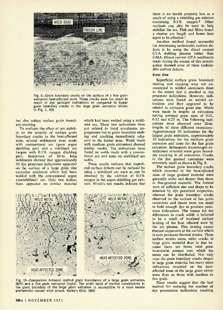
Fig. 9—Grain boundary cracks on the surface of a fine grain extrusion heat-affected zone. These cracks were too small to result in dye pentrant indications as compared to larger grain boundary cracks in the large grain extrusion shown in Fig. 1. 32X
but also reduce surface grain boundary cracking.
To evaluate the effect of arc stability on the severity of surface grain boundary cracks in .the heat-affected zone, several weldments were made with conventional arc (pure argon shielding gas) and a stabilized arc (argon with 0 .1% oxygen shielding gas). Inspection of 20-in. long weldments showed that approximately 30 dye penetrant indications appeared on the surface of a large grain size extrusion weldment which had been welded with the conventional argon (unstabilized) arc. Only two indications appeared on similar material
f 1 \ I / WELD METAL h <X%_ l i M 'i\M'-i^£^-Kh^'t^
which had been welded using a stabilized arc. These two indications were not related to local arc-plasma impingement but to grain boundary melting and cracking immediately adjacent to the fusion zone. Welds made with medium grain extrusions showed similar results. Ten indications were found on welds made with a conventional arc and none on stabilized arc welds.
These results indicate that superficial surface defects can be reduced by using a stabilized arc such as can be obtained by the addition of 0 .1% oxygen in the argon shielding gas mixture. Wroth's test results indicate that
' r »'<'''l ST? « i-y"'' *,, V / 7-'-'" **•••..:•• V ' * *
'"M '' i l '•''•'•;777
'****; "WX* "•;i'•'•
• * ' ' ¥ * • ' -• ^'•'::'7^'7-:.7l':77j' HEAT-AFFECTED ZONE
• \ . * ' i \ • 7'f S>
i.'\i
m
'••{uT-'Wf WELD METAL,
.'..#- - y.
HEAT-AFFECTED ZONE NE M
'•if.
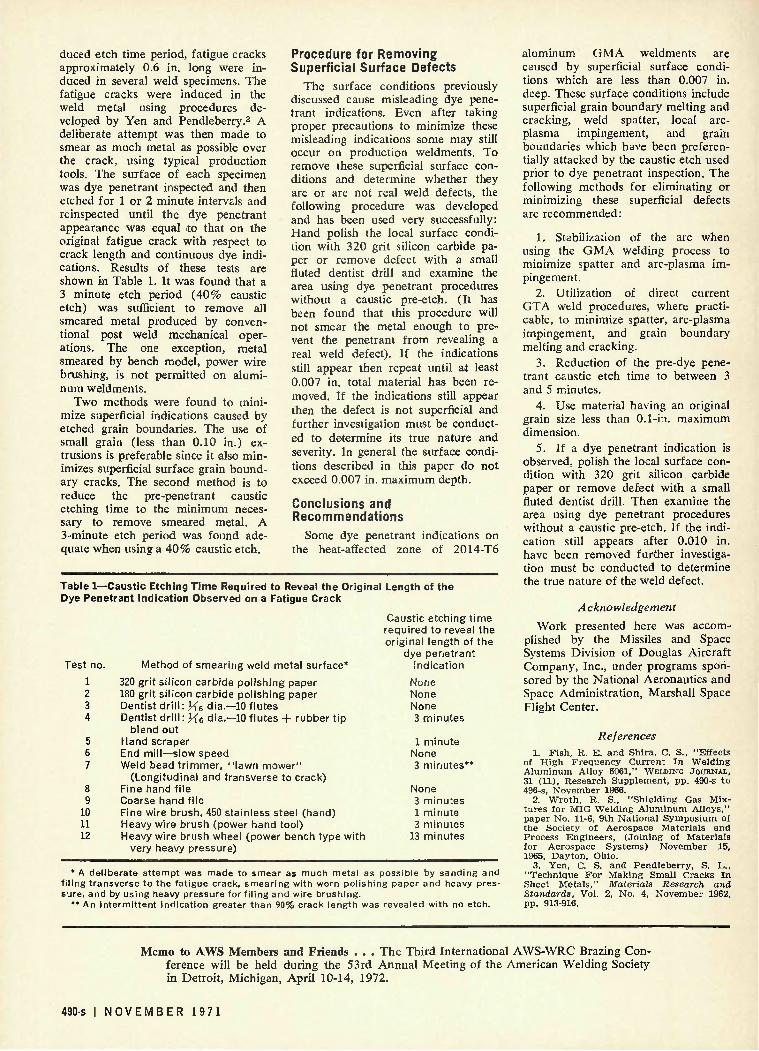
Fig. 10—Comparsion between melted grain boundaries of a large grain extrusion, (left) and a fine grain extrusion (right). The wider band of melted constituents in the grain boundary of the large grain extrusion is susceptible to a more severe preferential caustic etch attack. Keller's Etch. 500X
there is no tensile property loss as a result of using a shielding gas mixture containing 0 .1% oxygen.2 Other methods can also be used to help stabilize the arc. Fish and Shira found a shorter arc length and lower heat input to be effective.1
Another method found successful for minimizing undesirable surface defects is by using the direct current GTA welding process rather than GMA. Direct current GTA weldments made during the course of this investigation showed none of these undesirable surface defects.
Grain Size
Superficial surface grain boundary melting and cracking were not encountered in welded aluminum sheet to the extent that it resulted in dye penetrant indications. However, indications were found on welded extrusions and they appeared to be related to extrusion grain size. Welds were made in lengths of extrusions having nominal grain sizes of 0.01, 0.12 and 0.25 in. The following indications were observed over 20-in. lengths of three different extrusions: Approximately 30 indications for the largest grain extrusion, approximately 10 indications for the medium grain extrusion and none for the fine grain extrusion. Subsequent macroscopic examination revealed some grain boundary cracking in all extrusions. Cracks in the fine grained extrusions were extremely small as shown in Fig. 9.
The surface grain boundary cracks which occurred in the heat-affected zone of large grained material were generally wider and deeper than those in fine-grained material. The former were of sufficient size and shape to be detected by dye penetrant inspection, whereas the grain boundary cracks observed on the surface of fine grain extrusions and sheets were too small to hold enough dye to produce penetrant indications. The reason for the differences in crack width is believed to be a result of localized surface heating of the heat affected zone by the arc plasma. This heating causes thermal expansion at the surface which in turn produces thermal strains. These surface strains cause wider cracks in large grain material than in fine because there are fewer total grain boundaries present over which the strain can be distributed. Not only were the grain boundary cracks deeper in large grain material but many more indications occurred on the heat-affected zone of the large grain extrusions than on those with medium or fine grain.
These results suggest that the best method for reducing the number of dye penetration indications resulting
488-s I N O V E M B E R 1971

from superficial grain boundary melting and cracking on the surface of the heat-affected zone is to use fine grain material. It has been found that a weldment made with an extrusion having an original grain size less than 0.1-in. very seldom showed dye penetrant indications from grain boundary melting and cracking.
Caustic Etching Time
The penetrant indications found adjacent to the fusion line of extrusions which had been machined after welding were found to be influenced by both extrusion grain size and length of pre-penetrant caustic etch time.
The preferential chemical attack by the caustic etch on a machined surface was more severe on grain boundaries of large grain material than on those of fine grain material. The grain boundaries of large grain material when subjected to the high temperatures reached immediately adjacent to the fusion zone contain a wider band of melted constituents than corresponding fine grain boundaries as shown in Fig. 10. It is these melted constituents which provide a high chemical potential difference between the grain boundary area and the grain. Therefore, these areas are etched deeper in large grain material. As expected, increased etch time also increased the size of the etched grain boundaries as shown in the photo sequence of Fig. 11. Not only was melted grain boundary etched away more severely with increased etch time, but it was found that the number of dye penetrant indications increased with increased etch time. The machined surface of a 2-ft. length of the large grain extrusion weldment was dye penetrant inspected after a 3 minute etch, a 15 .minute etch and a 30 minute etch. No indications were observed after the 3 minute etch. Eight indications were detected after the 15 minute etch and twenty indications were observed after the 30 minute etch.
The logical approach to minimizing the occurrence of this type of dye penetrant indications therefore appeared to be to reduce the caustic etch time as much as possible without reducing its effectiveness. The purpose of the etch prior to dye penetrant inspection is to remove any smeared metal that may have resulted from post-weld processing. Mechanical processes that might cause smearing include removing of the weld smut, trimming the weld beads, or machining weldment surfaces. It was believed that an etch period much less than the currently used 15 minutes would be sufficient to remove all smeared metal caused by post-weld processing. To determine a suitable and effective re-
Fig. 11. Effect of caustic etch time on preferential attack on melted grain boundaries adjacent to the fusion zone. Sample was a polished cross-section of a large grain extrusion weldment. The degree of pitting in the melted grain boundaries and in the weld metal increased with increased etch time. 50X. (top) 5 minute caustic etch did not reveal dye penetrant indications; (middle) 15 minute caustic etch did reveal dye penetrant indications; (bottom) 30 minute caustic etch did reveal dye penetrant indications.
W E L D I N G R E S E A R C H S U P P L E M E N T | 489-s
duced etch time period, fatigue cracks approximately 0.6 in. long were induced in several weld specimens. The fatigue cracks were induced in the weld metal using procedures developed by Yen and Pendleberry.3 A deliberate attempt was then made to smear as much metal as possible over the crack, using typical production tools. The surface of each specimen was dye penetrant inspected and then etched for 1 or 2 minute intervals and reinspected until the dye penetrant appearance was equal to that on the original fatigue crack with respect to crack length and continuous dye indications. Results of these tests are shown in Table 1. It was found that a 3 minute etch period (40% caustic etch) was sufficient to remove all smeared metal produced by conventional post weld mechanical operations. The one exception, metal smeared by bench model, power wire brushing, is not permitted on aluminum weldments.
Two methods were found to minimize superficial indications caused by etched grain boundaries. The use of small grain (less than 0.10 in.) extrusions is preferable since it also minimizes superficial surface grain boundary cracks. The second method is to reduce the pre-penetrant caustic etching time to the minimum necessary to remove smeared metal. A 3-minute etch period was found adequate when using a 40% caustic etch.
Procedure for Removing Superficial Surface Defects
The surface conditions previously discussed cause misleading dye penetrant indications. Even after taking proper precautions to minimize these misleading indications some may still occur on production weldments. To remove these superficial surface conditions and determine whether they are or are not real weld defects, the following procedure was developed and has been used very successfully: Hand polish the local surface condition with 320 grit silicon carbide paper or remove defect with a small fluted dentist drill and examine the area using dye penetrant procedures without a caustic pre-etch. (It has been found that this procedure will not smear the metal enough to prevent the penetrant from revealing a real weld defect). If the indications still appear then repeat until at least 0.007 in. total material has been removed. If the indications still appear then the defect is not superficial and further investigation must be conducted to determine its true nature and severity. In general the surface conditions described in this paper do not exceed 0.007 in. maximum depth.
Conclusions and Recommendations
Some dye penetrant indications on the heat-affected zone of 2014-T6
Table 1—Caustic Etching Time Required to Reveal the Original Length of the Dye Penetrant Indication Observed on a Fatigue Crack
Caustic etching time required to reveal the original length of the
dye penetrant indication Test no. Method of smearing weld metal surface*
1 320 grit silicon carbide polishing paper 2 180 grit silicon carbide polishing paper 3 Dentist dr i l l : He dia.—10 flutes 4 Dentist dr i l l : H 6 dia.—10 flutes + rubber tip
blend out 5 Hand scraper 6 End mill—slow speed 7 Weld bead trimmer, "lawn mower"
(Longitudinal and transverse to crack) 8 Fine hand file 9 Coarse hand file
10 Fine wire brush, 450 stainless steel (hand) 11 Heavy wire brush (power hand tool) 12 Heavy wire brush wheel (power bench type with
very heavy pressure)
None None None 3 minutes
1 minute None 3 minutes*
None 3 minutes 1 minute 3 minutes
13 minutes
• A deliberate attempt was made to smear as much metal as possible by sanding and f i l ing transverse to the fatigue crack, smearing with worn polishing paper and heavy pressure, and by using heavy pressure for f i l ing and wire brushing.
** An intermit tent indication greater than 90% crack length was revealed with no etch.
aluminum GMA weldments are caused by superficial surface conditions which are less than 0.007 in. deep. These surface conditions include superficial grain boundary melting and cracking, weld spatter, local arc-plasma impingement, and grain boundaries which have been preferentially attacked by the caustic etch used prior to dye penetrant inspection. The following methods for eliminating or minimizing these superficial defects are recommended:
1. Stabilization of the arc when using the GMA welding process to minimize spatter and arc-plasma impingement.
2. Utilization of direct current GTA weld procedures, where practicable, to minimize spatter, arc-plasma impingement, and grain boundary melting and cracking.
3. Reduction of the pre-dye penetrant caustic etch time to between 3 and 5 minutes.
4. Use material having an original grain size less than 0.1-in. maximum dimension.
5. If a dye penetrant indication is observed, polish the local surface condition with 320 grit silicon carbide paper or remove defect with a small fluted dentist drill. Then examine the area using dye penetrant procedures without a caustic pre-etch. If the indication still appears after 0.010 in. have been removed further investigation must be conducted to determine the true nature of the weld defect.
Acknowledgement
Work presented here was accomplished by the Missiles and Space Systems Division of Douglas Aircraft Company, Inc., under programs sponsored by the National Aeronautics and Space Administration, Marshall Space Flight Center.
References 1. Fish , R. E. and Shira, C. S., "Effects
of High Frequency Curren t In Welding Aluminum Alloy 6061," WELDING JOURNAL, 31 (11), Research Supplement , pp. 490-s to 496-s, November 1966.
2. Wroth , R. S., "Shielding Gas Mixtures for MIG Welding Aluminum Alloys," paper No. 11-6, 9th Nat ional Symposium of the Society of Aerospace Mater ia ls and Process Engineers , ( Jo in ing of Mater ials for Aerospace Systems) November 15, 1965, Dayton, Ohio.
3. Yen, C. S. and Pendleber ry , S. L., "Techn ique F o r Making Small Cracks In Sheet Meta l s , " Materials Research and Standards, Vol. 2, No. 4, November 1962, pp. 913-916.
Memo to AWS Members and Friends . . . The Third International AWS-WRC Brazing Conference will be held during the 53rd Annual Meeting of the American Welding Society in Detroit, Michigan, April 10-14, 1972.
490-s I N O V E M B E R 1971