dwyer instruments, inc. 2015 catalog · magnehelic® differential pressure gages much easier by...
TRANSCRIPT

AC
CESSO
RIES | TA
BLE
OF C
ON
TEN
TS
Fittings,Nylon
pages 543-544
Gage Guards/Pressure Snubbers
pages 534-535Strap Wrench
page 535
Fittings,Stainless Steelpages 536-542
Pneumatic Fittingspages 545-546
Gage Tubingpage 547
Static PressureSensors
pages 548-549Pneumatic Valves
page 544
MiscellaneousAccessories
pages 550-551
Filterspage 532
Siphons/CoolingExtensions
pages 533-534
531CALL TO ORDER | 800-876-0036
531_Layout 1 7/8/14 9:07 AM Page 531
Distributed by: M&M Control Service, Inc. www.mmcontrol.com/Dwyer.php 800-876-0036 847-356-0566

DWYER INSTRUMENTS, INC.532
Filte
rsA
CC
ESSO
RIE
S
SPECIFICATIONSFiltration Efficiency: 93% (removal of 0.01 micron particles). Maximum Pressure: 150 psig (10 bar).Maximum Temperature: 130°F (54°C).Max. Flow at 100 psig: 22 SCFM (F222); 45 SCFM (F451).Inlet & Outlet Ports: 1/4˝ female NPT.Mounting: In-line only (F222); 1/4-20 mounting holes (F451).Materials of Construction: Anodized aluminum head, polycarbonate bowl,cadmium plated steel tie rod, nylon internals, Buna-N seal. Weight: 0.5 lb (0.2 kg) (F222); 1.1 lb (0.5 kg) (F451).
Liquid/Particle Filters
Compressed air filters protect equipment and instrumentation from harmfulcontaminant's such as dirt, water and oil. Liquids are continuously coalesced and releasedthrough the manual drain valves. Replaceable filter element removes particles and dropletsas small as 0.01 micron with 93% efficiency. Units have 1/4˝ female NPT inlet and outlet andmanual drain valve.
F222 F451
1/4˝ NPT1/4˝ NPT
ModelF222
&F451
Remove 99.99% of unwanted particles from within your gas flow with the ModelF195 Disposable In-Line Filter. Encapsulated microfiber filter elements are able to filterparticles as small as 0.1 micron. Filters are completely disposable — simply remove thefilter from your line and throw it away when it becomes dirty. The transparent nylonhousing makes it simple to determine if the filter needs to be changed.
SPECIFICATIONSFiltration Efficiency: 99.99% (removal of 0.1 micron particles).Housing Construction: Nylon.Filter Tube Dimensions: 0.59 ID x 1.39 L.Maximum Temperature: 230˚F @ 0 psig (110˚C @ 0 bar), 120˚F @ 125 psig(49˚C @ 9 bar).Maximum Pressure: 125 psig (8.6 bar).Maximum Differential Pressure: 60 psi (4 bar) (in-to-out flow direction), 20 psi(1.4 bar) (out-to-in flow direction).Internal Volume: 11.5 cc (11.5 ml). Connections: Barbed for 1/4˝ ID tubing.
Ø1.100[27.94]
.750[19.05]
.750[19.05]
3.220[81.79]
Ø.250[6.35]
Ø.100[2.54]
Line Pressure (psig) 1.5 10 20 30 40 60 80 100 125 Gas Flow (scfm) 0.6 0.9 1.3 1.6 2.0 2.7 3.5 4.2 5.7
* 1.5 psi pressure drop.
Line Pressure vs. Flow
ModelF195 Disposable In-Line Filter
Flowmeter Accessories and Options
Model F222, Liquid/Particle Filter . . . . . . . . . . . . . . . . . . . . . . . . . . . . . . .Model F451, Liquid/Particle Filter . . . . . . . . . . . . . . . . . . . . . . . . . . . . . . .Model 1201-3, Replacement Filters for F451 (pk of 3) . . . . . . . . . . . . . . . .
Model F195, Disposable In-Line Filter . . . . . . . . . . . . . . . . . . . . . . . . . . . . .
532_Layout 1 7/15/14 9:54 AM Page 532
Distributed by: M&M Control Service, Inc. www.mmcontrol.com/Dwyer.php 800-876-0036 847-356-0566

533
SPECIFICATIONSService: Compatible liquids and gases.Wetted Materials: Carbon steel.Pressure Limits: 500 psi (34 bar).Temperature Limits: 680°F (360°C).Process Connections: See chart.Weight: 1/4˝ NPT models: 8 oz (226.8 g); 1/2˝ NPT models: 34.9 oz (988.8 g).
ModelA-169-CA-169-D
The Carbon Steel Siphons protect pressure instruments in high temperatureapplications. Water held in the 180° coil prevents steam from contacting the instrument.Constructed with carbon steel, the A-169 siphons can withstand high temperature andpressure. They are ideal for use with pressure gages and instrumentation where the processmedia temperature exceeds the rating of the instrument. The male NPT connection allowsfor easy installation and secure attachment.
Carbon Steel SiphonsSeriesA-169
MALE 1/2˝ NPTCONNECTION BOTH ENDS
9-19/32[243.72]
4-17/64[108.44]
2-15/32[62.76]
MALE 1/4˝ NPTCONNECTIONBOTH ENDS
5-3/32[129.54]
2-7/16[61.87]
1-13/64[30.39]
ProcessConnections1/4˝ NPT male1/2˝ NPT male
316 Stainless Steel SiphonsSeriesA-170
SPECIFICATIONSService: Compatible liquids and gases.Wetted Materials: 316 SS.Pressure Limits: See chart.Temperature Limits: See chart.Process Connections: See chart.Weight: 1/4˝ NPT models: 8 oz (226.8 g); 1/2˝ NPT models: 25.6 oz (725.75 g).Agency Approvals: RoHS. *Model A-170 is not RoHS certified.
The 316 Stainless Steel Siphons protect pressure instruments in high temperatureapplications. Water held in the 180° coil prevents steam from contacting the instrument.Constructed with 316 stainless steel, the A-170 siphons offer the best resistance to corrosion,high temperature, and pressure. They are ideal for use with pressure gages andinstrumentation where the process media temperature exceeds the rating of the instrument.The male NPT connection allows for easy installation and secure attachment.
ModelA-170*A-170-AA-170-B
ProcessConnections1/4˝ NPT male1/4˝ NPT male1/2˝ NPT male
Material316 SS SCH80316 SS SCH40316 SS SCH40
2-13/32[60.96]
1[25.40]
MALE 1/4˝ NPTCONNECTIONBOTH ENDS
4-19/32[116.84]
MALE 1/2˝ NPTCONNECTIONBOTH ENDS 9-13/64
[233.68]
2-19/64[58.38]
4-1/8[104.78]
RoHS
Model A-170-A
Model A-170-B
Model A-169-C
Model A-169-D
Siphons/Cooling Extensions
AC
CESSO
RIES
CALL TO ORDER | 800-876-0036
MaterialCarbon Steel SCH 80Carbon Steel SCH 80
Pressure Limit2307 psi @ 200°F500 psi @ 680°F500 psi @ 680°F
533_Layout 1 7/15/14 9:54 AM Page 533
Distributed by: M&M Control Service, Inc. www.mmcontrol.com/Dwyer.php 800-876-0036 847-356-0566

DWYER INSTRUMENTS, INC.534
Siph
ons/
Coo
ling
Exte
nsio
nsA
CC
ESSO
RIE
S
Perforated or Spiral Cooling TowerProtect Instrumentation in High Temperature Applications
SPECIFICATIONSService: Compatible liquids and gases.Wetted Parts: 316L SS.Temperature Limits: 428°F (220°C).Pressure Limits: 5800 psi (400 bar).Process Connections: See chart.Height: 6˝ (150 mm).Weight: 8 oz (227 g).
ModelA-240-AA-240-BA-240-CA-240-DA-240-EA-240-F
ModelA-250-AA-250-BA-250-CA-250-DA-250-EA-250-F
StylePerforatedPerforatedPerforatedPerforatedPerforatedPerforated
StyleSpiralSpiralSpiralSpiralSpiralSpiral
PROCESS CONNECTION
PROCESS CONNECTION
B
B
[5-29/32][150]
5-27/35[148.80]
APROCESS CONNECTION
APROCESS CONNECTION
The Perforated and Spiral Cooling Towers protect pressure instruments during hightemperature applications. Both the spiral and perforated styles are made with 316L SS,and are available with various process connections in NPT or BSPP style. Both CoolingTowers are ideal for use with pressure gages, switches, and transmitters where the processmedia temperature exceeds the rating of the instrument.
A-240 A-250
Adjustable Pressure SnubberProtect Instruments from Pressure Spikes or Fluid Hammer
SPECIFICATIONSService: Compatible liquids and gases.Wetted Parts: Brass or 316 SS.Pressure Limits: 5690 psi (392 bar).Temperature Limits: -4 to 302°F (-20 to 150°C).Process Connections: See chart.Weight: 8.4 oz (238 g).
A
A
[A]
[B]
[C]
[HEX “H”]Brass 316 SS
DimensionsC131620
B424440
Connections1/4˝ M x F3/8˝ M x F1/2˝ M x F
A556060
H25.025.028.0
The Adjustable Pressure Snubbers protect pressure instruments against fluctuations,surges, spikes and fluid hammer. The fine thread adjustable valve allows you to fine tuneharmful harmonic vibration from the fluid systems and isolate the instrument from processwhen service or replacement is necessary. These Pressure Snubbers are designed toprovide fully field adjustable dampening. By using our Adjustable Pressure Snubbers, youwill alleviate surges and pulsations to assure steady pressure readings and extend the lifeof your instrument.
1/4˝ male/female NPT3/8˝ male/female NPT1/2˝ male/female NPT1/4˝ male/female BSPP3/8˝ male/female BSPP1/2˝ male/female BSPP
Connection Chart
ModelA-251A-252A-253A-254A-255A-256
MaterialBrassBrassBrassBrassBrassBrass
ModelA-257A-258 A-259A-260A-261A-262
Material316 SS316 SS316 SS316 SS316 SS316 SS
SeriesA-240/A-250
Connections1/4˝ male/female BSPP3/8˝ male/female BSPP1/2˝ male/female BSPP1/4˝ male/female NPT3/8˝ male/female NPT1/2˝ male/female NPT
Connections1/4˝ male/female BSPP3/8˝ male/female BSPP1/2˝ male/female BSPP1/4˝ male/female NPT3/8˝ male/female NPT1/2˝ male/female NPT
Connections1/4˝ male/female NPT3/8˝ male/female NPT1/2˝ male/female NPT1/4˝ male/female BSPP3/8˝ male/female BSPP1/2˝ male/female BSPP
Connections1/4˝ male/female NPT3/8˝ male/female NPT1/2˝ male/female NPT1/4˝ male/female BSPP3/8˝ male/female BSPP1/2˝ male/female BSPP
534_Layout 1 7/15/14 9:53 AM Page 534
Distributed by: M&M Control Service, Inc. www.mmcontrol.com/Dwyer.php 800-876-0036 847-356-0566

535
Gage G
uards/Pressure Snubbers
AC
CESSO
RIES
SPECIFICATIONSMaximum Pressure: Liquids: 160 psi(11 bar) @ 70 to 185°F (21 to 85°C);Gases: 100 psi (6.9 bar) @ 70 to 100°F(21 to 38°C) and 30 psi (2.1 bar) @ 100to 185°F (38 to 85°C).Accuracy: ±4%.
Maximum Temperature: 185°F(85°C).Wetted Parts: Glass-filledpolypropylene housing, Buna-N orfluoroelastomer diaphragm.Dimensions: 1/4˝ female NPTinstrument side; 1/2˝ male NPT systemside; 1-3/8˝ (35 mm) diameter.
Protecting pressure or vacuum instruments from clogging, corrosion, or damage, the SeriesGG Gage Guard provides a protective barrier between the process fluid and the instrument.The hermetically-sealed uni-body protects from the possibility of leaking. Glass-filledPolypropylene housing is suitable for most inorganic chemicals and temperatures up to 185°F(85°C). A fluid fill station is recommended for proper installation.
SPECIFICATIONSMaximum Pressure: Brass: 10,000 psi (689 bar), SS: 15,000 psi (1034 bar).Filter Disc Material: AISI 316 SS.Approx. Micron Rating: Air & gases: 2-5µ; water & oils (30-225 SSU): 10µ.Dimensions: 1/4˝ NPT: 3/4˝ (19 mm) hex size, 1.5˝ (38 mm) length.
Designed to protect pressure instrumentation by dampening surges and pulsations andassuring steady average pressure readings. Snubbers are available in a variety of poresizes for use with gases, water, and oils.
Model PS114PS214PS122PS124PS222PS224PS225
ServiceAir & GasesAir & GasesWater & OilsAir & GasesWater & OilsAir & GasesPulsating Gas
SeriesGG Gage Guard
Strap Wrench
The SWUK1 offers the user a versatile tool to grip, undo & tighten a wide variety ofawkwardly shaped and sized objects. The SWUK1 also makes the job of fitting Adjustable Signal Flags (ASF) covers toMagnehelic® Differential Pressure Gages much easier by simply following the instructionincluded with each cover supplied.
FEATURES• Reinforced plastic handle provides extra leverage.• Rubber strap reinforced with 38 cords of high tensile polycarbon to give a
breaking strength in excess of 2000 lb.• Strap will grip objects from .79˝ to 6.30˝ diameter.• Low cost, rugged and simple to use.• Handy multi-purpose tool.
ModelSWUK1
SeriesPS Pressure Snubber
1-23/32[43.66]
SYSTEM SIDE1/2 MALE NPT 1-25/64 [35.32]
INSTRUMENT SIDE1/4 FEMALE NPT
ModelPS114PS214PS122PS124PS222PS224PS225
A1/8˝ NPT1/8˝ NPT1/4˝ NPT1/4˝ NPT1/4˝ NPT1/4˝ NPT1/4˝ NPT
B1/2˝1/2˝3/4˝3/4˝3/4˝3/4˝3/4˝
C1-7/64˝1-7/64˝1-1/2˝1-1/2˝1-1/2˝1-1/2˝1-1/2˝
C
B
A
3-13/16[96.84]
8 [203.2]RUBBER STRAPØ1 UP TO Ø6-3/8
[25.4] UP TO[161.93]
Dimension
CALL TO ORDER | 800-876-0036
Model GG1, (Buna-N diaphragm) . . . . . . . . . . . . . . . . . . . . . . . . . . . . . .Model GG2, (Fluoroelastomer diaphragm) . . . . . . . . . . . . . . . . . . . . . . . . .
ConstructionBrass 1/8˝ NPTSS 1/8˝ NPTBrass 1/4˝ NPTBrass 1/4˝ NPTSS 1/4˝ NPTSS 1/4˝ NPTSS 1/4˝ NPT
Model SWUK1 . . . . . . . . . . . . . . . . . . . . . . . . . . . . . . . . . . . . . . . . . . . . . . .
535_Layout 1 7/15/14 9:52 AM Page 535
Distributed by: M&M Control Service, Inc. www.mmcontrol.com/Dwyer.php 800-876-0036 847-356-0566
DWYER INSTRUMENTS, INC.536
Fitti
ngs,
Stai
nles
s St
eel
AC
CES
SOR
IES
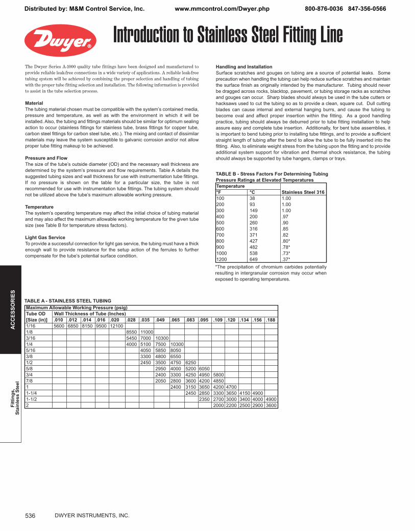
Introduction to Stainless Steel Fitting LineThe Dwyer Series A-1000 quality tube fittings have been designed and manufactured toprovide reliable leak-free connections in a wide variety of applications. A reliable leak-freetubing system will be achieved by combining the proper selection and handling of tubingwith the proper tube fitting selection and installation. The following information is providedto assist in the tube selection process.
MaterialThe tubing material chosen must be compatible with the system’s contained media,pressure and temperature, as well as with the environment in which it will beinstalled. Also, the tubing and fittings materials should be similar for optimum sealingaction to occur (stainless fittings for stainless tube, brass fittings for copper tube,carbon steel fittings for carbon steel tube, etc.). The mixing and contact of dissimilarmaterials may leave the system susceptible to galvanic corrosion and/or not allowproper tube fitting makeup to be achieved.
Pressure and FlowThe size of the tube’s outside diameter (OD) and the necessary wall thickness aredetermined by the system’s pressure and flow requirements. Table A details thesuggested tubing sizes and wall thickness for use with instrumentation tube fittings.If no pressure is shown on the table for a particular size, the tube is notrecommended for use with instrumentation tube fittings. The tubing system shouldnot be utilized above the tube’s maximum allowable working pressure.
TemperatureThe system’s operating temperature may affect the initial choice of tubing materialand may also affect the maximum allowable working temperature for the given tubesize (see Table B for temperature stress factors).
Light Gas ServiceTo provide a successful connection for light gas service, the tubing must have a thickenough wall to provide resistance for the setup action of the ferrules to furthercompensate for the tube’s potential surface condition.
Handling and Installation Surface scratches and gouges on tubing are a source of potential leaks. Someprecaution when handling the tubing can help reduce surface scratches and maintainthe surface finish as originally intended by the manufacturer. Tubing should neverbe dragged across rocks, blacktop, pavement, or tubing storage racks as scratchesand gouges can occur. Sharp blades should always be used in the tube cutters orhacksaws used to cut the tubing so as to provide a clean, square cut. Dull cuttingblades can cause internal and external hanging burrs, and cause the tubing tobecome oval and affect proper insertion within the fitting. As a good handlingpractice, tubing should always be deburred prior to tube fitting installation to helpassure easy and complete tube insertion. Additionally, for bent tube assemblies, itis important to bend tubing prior to installing tube fittings, and to provide a sufficientstraight length of tubing after the bend to allow the tube to be fully inserted into thefitting. Also, to eliminate weight stress from the tubing upon the fitting and to provideadditional system support for vibration and thermal shock resistance, the tubingshould always be supported by tube hangers, clamps or trays.
Tube OD[Size (in)]1/161/83/161/45/163/81/25/83/47/811-1/41-1/22
.0105600
.0126850
.0148150
.0169500
.02012100
.028
855054504000
.035
1100070005100405033002450
.049
103007500585048003500295024002050
.065
103008050655047504000330028002400
.083
625052004250360031502450
.095
605049504200365028502350
.109
580048504200330027002000
.120
4700365030002200
.134
415034002500
.156
490040002900
.188
49003600
Wall Thickness of Tube (Inches)Maximum Allowable Working Pressure (psig)
Temperature°F10020030040050060070080090010001200
TABLE B - Stress Factors For Determining TubingPressure Ratings at Elevated Temperatures
°C3893149200260316371427482538649
Stainless Steel 3161.001.001.00.97.90.85.82.80*.78*.73*.37*
*The precipitation of chromium carbides potentiallyresulting in intergranular corrosion may occur whenexposed to operating temperatures.
TABLE A - STAINLESS STEEL TUBING
536_Layout 1 7/8/14 9:01 AM Page 536
Distributed by: M&M Control Service, Inc. www.mmcontrol.com/Dwyer.php 800-876-0036 847-356-0566

537
Fittings,Stainless Steel
AC
CESSO
RIES
Stainless Steel Fitting LineSeriesA-1000
Series A-1001 Male Elbow Fitting Line
SPECIFICATIONSService: Liquid, steam and compatible gases.Wetted Materials: 316 SS.Temperature Ranges: See reference Table B.�Pressure Ranges: See reference Table A.�Connections: 1/16˝ to 1-1/2˝.Dimensions: Consult website, or contact factory.
H WRENCH PAD
BY
F
EP PIPE THREAD
CD
T
G NUTHEX
ABX
G NUT HEX B BODYF
E
P PIPE THREADH BODY HEX
AC
D
T
Series A-1002 Male Connector Fitting LineSPECIFICATIONSService: Liquid, steam and compatible gases.Wetted Materials: 316 SS.Temperature Ranges: See reference Table B.�Pressure Ranges: See reference Table A.�Connections: 1/16˝ to 2˝.Dimensions: Consult website, or contact factory.
ModelA-1001-1A-1001-2A-1001-3A-1001-4A-1001-5A-1001-6A-1001-7A-1001-8A-1001-9A-1001-10A-1001-11
T = Tube OD1/16˝1/16˝1/8˝1/8˝1/8˝3/16˝3/16˝1/4˝1/4˝1/4˝1/4˝
ModelA-1001-12A-1001-13A-1001-15A-1001-16A-1001-17A-1001-18A-1001-19A-1001-20A-1001-21A-1001-22A-1001-23
T = Tube OD5/16˝5/16˝3/8˝3/8˝3/8˝3/8˝3/8˝1/2˝1/2˝1/2˝1/2˝
ModelA-1001-24A-1001-25A-1001-26A-1001-27A-1001-28A-1001-29A-1001-30A-1001-31A-1001-32A-1001-33
T = Tube OD5/8˝5/8˝5/8˝3/4˝3/4˝7/8˝1˝1˝1-1/4˝1-1/2˝
ModelA-1002-1A-1002-2A-1002-3A-1002-4A-1002-5A-1002-6A-1002-7A-1002-8A-1002-9A-1002-10A-1002-11A-1002-12A-1002-13A-1002-15A-1002-16
T = Tube OD1/16˝1/16˝1/16˝1/8˝1/8˝1/8˝1/8˝1/8˝3/16˝3/16˝1/4˝1/4˝1/4˝1/4˝1/4˝
ModelA-1002-17A-1002-18A-1002-19A-1002-20A-1002-21A-1002-22A-1002-23A-1002-24A-1002-25A-1002-26A-1002-27A-1002-28A-1002-29A-1002-30A-1002-31
T = Tube OD5/16˝5/16˝5/16˝3/8˝3/8˝3/8˝3/8˝3/8˝1/2˝1/2˝1/2˝1/2˝1/2˝5/8˝5/8˝
ModelA-1002-32A-1002-33A-1002-34A-1002-35A-1002-36A-1002-37A-1002-39A-1002-40A-1002-41A-1002-42A-1002-43A-1002-44A-1002-45
T = Tube OD5/8˝5/8˝3/4˝3/4˝3/4˝7/8˝1˝1˝1˝1-1/4˝1-1/4˝1-1/2˝2˝
Table B: See page 536 (Introduction to Stainless Steel Fitting Line)Table A: See page 536 (Introduction to Stainless Steel Fitting Line)
Table B: See page 536 (Introduction to Stainless Steel Fitting Line)Table A: See page 536 (Introduction to Stainless Steel Fitting Line)
CALL TO ORDER | 800-876-0036
P = Pipe Thread Male1/16˝1/8˝1/16˝1/8˝1/4˝1/8˝1/4˝1/8˝1/4˝3/8˝1/2˝
P = Pipe Thread Male1/8˝1/4˝1/8˝1/4˝3/8˝1/2˝3/4˝1/4˝3/8˝1/2˝3/4˝
P = Pipe Thread Male3/8˝1/2˝3/4˝1/2˝3/4˝3/4˝3/4˝1˝1-1/4˝1-1/2˝
P = Pipe Thread Male1/16˝1/8˝1/4˝1/16˝1/8˝1/4˝3/8˝1/2˝1/8˝1/4˝1/16˝1/8˝1/4˝1/2˝3/4˝
P = Pipe Thread Male1/8˝1/4˝3/8˝1/8˝1/4˝3/8˝1/2˝3/4˝1/8˝1/4˝3/8˝1/2˝3/4˝3/8˝1/2˝
P = Pipe Thread Male1/2˝3/4˝1/2˝3/4˝1˝3/4˝1/2˝3/4˝1˝1˝1-1/4˝1-1/2˝2˝
537_Layout 1 7/15/14 9:45 AM Page 537
Distributed by: M&M Control Service, Inc. www.mmcontrol.com/Dwyer.php 800-876-0036 847-356-0566

DWYER INSTRUMENTS, INC.538
Fitti
ngs,
Stai
nles
s St
eel
AC
CES
SOR
IES
Stainless Steel Fitting LineSeriesA-1000
Series A-1003 Union Fitting Line
SPECIFICATIONSService: Liquid, steam and compatible gases.Wetted Materials: 316 SS.Temperature Ranges: See reference Table B.�Pressure Ranges: See reference Table A.�Connections: 1/16˝ to 2˝.Dimensions: Consult website, or contact factory.
B BODYH BODYHEX
G NUT HEX
T
DC
AC
D
ET
G NUT HEX
AC
D
ET
BX
H WRENCH PAD
A
T
G NUT HEX
Series A-1004 Union Elbow Fitting LineSPECIFICATIONSService: Liquid, steam and compatible gases.Wetted Materials: 316 SS.Temperature Ranges: See reference Table B.�Pressure Ranges: See reference Table A.�Connections: 1/16˝ to 2˝.Dimensions: Consult website, or contact factory.
B BODY G NUT HEX
E T
DC
AX
AAX
BX
AX
BX
BXH WRENCHPAD
Series A-1005 Union Tee Fitting LineSPECIFICATIONSService: Liquid, steam and compatible gases.Wetted Materials: 316 SS.Temperature Ranges: See reference Table B.�Pressure Ranges: See reference Table A.�Connections: 1/16˝ to 2˝.Dimensions: Consult website, or contact factory.
ModelA-1003-1A-1003-2A-1003-3A-1003-4A-1003-5
ModelA-1003-6A-1003-7A-1003-8A-1003-9A-1003-10
ModelA-1003-11A-1003-12A-1003-13A-1003-14
ModelA-1004-1A-1004-2A-1004-3A-1004-4A-1004-5
ModelA-1004-6A-1004-7A-1004-8A-1004-9A-1004-10
ModelA-1004-11A-1004-12A-1004-13A-1004-14
ModelA-1005-1A-1005-2A-1005-3A-1005-4A-1005-5
ModelA-1005-6A-1005-7A-1005-8A-1005-9A-1005-11
ModelA-1005-12A-1005-13A-1005-14
�Table B: See page 536 (Introduction to Stainless Steel Fitting Line)�Table A: See page 536 (Introduction to Stainless Steel Fitting Line)
�Table B: See page 536 (Introduction to Stainless Steel Fitting Line)�Table A: See page 536 (Introduction to Stainless Steel Fitting Line)
�Table B: See page 536 (Introduction to Stainless Steel Fitting Line)�Table A: See page 536 (Introduction to Stainless Steel Fitting Line)
T = Tube OD3/8˝1/2˝5/8˝3/4˝7/8˝
T = Tube OD1˝1-1/4˝1-1/2˝2˝
T = Tube OD1/16˝1/8˝3/16˝1/4˝5/16˝
T = Tube OD3/8˝1/2˝5/8˝3/4˝7/8˝
T = Tube OD1˝1-1/4˝1-1/2˝2˝
T = Tube OD1/16˝1/8˝3/16˝1/4˝5/16˝
T = Tube OD3/8˝1/2˝5/8˝3/4˝1˝
T = Tube OD1-1/4˝1-1/2˝2˝
T = Tube OD1/16˝1/8˝3/16˝1/4˝5/16˝
538_Layout 1 7/15/14 9:44 AM Page 538
Distributed by: M&M Control Service, Inc. www.mmcontrol.com/Dwyer.php 800-876-0036 847-356-0566

539
Fittings,Stainless Steel
AC
CESSO
RIES
Stainless Steel Fitting LineSeriesA-1000
Series A-1006 Front Ferrule Fitting Line
SPECIFICATIONSService: Liquid, steam and compatible gases.Wetted Materials: 316 SS.Temperature Ranges: See reference Table B.�Pressure Ranges: See reference Table A.�Connections: 1/16˝ to 2˝.
T
T
Series A-1007 Back Ferrule Fitting Line
SPECIFICATIONSService: Liquid, steam and compatible gases.Wetted Materials: 316 SS.Temperature Ranges: See reference Table B.�Pressure Ranges: See reference Table A.�Connections: 1/16˝ to 2˝.
G NUT HEX
T
L
Series A-1008 Nut Fitting Line
SPECIFICATIONSService: Liquid, steam and compatible gases.Wetted Materials: 316 SS.Temperature Ranges: See reference Table B.�Pressure Ranges: See reference Table A.�Connections: 1/16˝ to 2˝.Dimensions: Consult website, or contact factory.
ModelA-1008-8A-1008-9A-1008-10A-1008-11A-1008-12A-1008-13A-1008-14
ModelA-1007-1A-1007-2A-1007-3A-1007-4A-1007-5A-1007-6A-1007-7
ModelA-1008-1A-1008-2A-1008-3A-1008-4A-1008-5A-1008-6A-1008-7
ModelA-1007-8A-1007-9A-1007-10A-1007-11A-1007-12A-1007-13A-1007-14
ModelA-1006-8A-1006-9A-1006-10A-1006-11A-1006-12A-1006-13A-1006-14
ModelA-1006-1A-1006-2A-1006-3A-1006-4A-1006-5A-1006-6A-1006-7
SPECIFICATIONSService: Liquid, steam and compatible gases.Wetted Materials: 316 SS.Temperature Ranges: See reference Table B.�Pressure Ranges: See reference Table A.�Connections: 1/8˝ to 1/2˝.Dimensions: Consult website or contact factory.
DC
HG HEX
BA
E F
Series A-1012 Stainless Steel Fitting LineModelA-1012-1A-1012-2A-1012-3A-1012-4A-1012-6A-1012-9
Hose Barb1/8˝1/8˝1/4˝1/4˝3/8˝1/2˝
Table B: See page 536 (Introduction to Stainless Steel Fitting Line)Table A: See page 536 (Introduction to Stainless Steel Fitting Line)
Table B: See page 536 (Introduction to Stainless Steel Fitting Line)Table A: See page 536 (Introduction to Stainless Steel Fitting Line)
Table B: See page 536 (Introduction to Stainless Steel Fitting Line)Table A: See page 536 (Introduction to Stainless Steel Fitting Line)
Table B: See page 536 (Introduction to Stainless Steel Fitting Line)Table A: See page 536 (Introduction to Stainless Steel Fitting Line)
CALL TO ORDER | 800-876-0036
Price$3.20n2.10n2.20n1.80n2.30n2.10n2.90n
T = Tube OD1/16˝1/8˝3/16˝1/4˝5/16˝3/8˝1/2˝
T = Tube OD5/8˝3/4˝7/8˝1˝1-1/4˝1-1/2˝2˝
Price$5.20n3.50n3.20n3.20n3.20n4.30n6.80n
T = Tube OD1/16˝1/8˝3/16˝1/4˝5/16˝3/8˝1/2˝
T = Tube OD5/8˝3/4˝7/8˝1˝1-1/4˝1-1/2˝2˝
Price$3.50n2.20n2.30n1.80n2.30n2.20n3.20n
T = Tube OD1/16˝1/8˝3/16˝1/4˝5/16˝3/8˝1/2˝
T = Tube OD5/8˝3/4˝7/8˝1˝1-1/4˝1-1/2˝2˝
T = Tube OD1/8˝1/4˝1/4˝3/8˝3/8˝1/2˝
539_Layout 1 7/15/14 9:41 AM Page 539
Distributed by: M&M Control Service, Inc. www.mmcontrol.com/Dwyer.php 800-876-0036 847-356-0566

DWYER INSTRUMENTS, INC.540
Fitti
ngs,
Stai
nles
s St
eel
AC
CES
SOR
IES
Stainless Steel Fitting LineSeriesA-1000
Series A-1009 Ferrule Set Fitting LineSPECIFICATIONSService: Liquid, steam and compatible gases.Wetted Materials: 316 SS.Temperature Ranges: See reference Table B.�Pressure Ranges: See reference Table A.�Connections: 1/16˝ to 2˝.
T
B BODY
H BODY HEX
T
D
CA
AXD
E
G NUT HEX
BXH JAM NUT HEX
Series A-1010 Bulkhead Union Fitting LineSPECIFICATIONSService: Liquid, steam and compatible gases.Wetted Materials: 316 SS.Temperature Ranges: See reference Table B.�Pressure Ranges: See reference Table A.�Connections: 1/16˝ to 1˝.Dimensions: Consult website, or contact factory.
Series A-1011 Female Connector Fitting LineSPECIFICATIONSService: Liquid, steam and compatible gases.Wetted Materials: 316 SS.Temperature Ranges: See reference Table B.�Pressure Ranges: See reference Table A.�Connections: 1/16˝ to 1-1/2˝.Dimensions: Consult website, or contact factory.
G NUT HEX B BODY
PPIPE THREAD
HBODY HEX
T
DC
A
ModelA-1009-1A-1009-2A-1009-3A-1009-4A-1009-5A-1009-6A-1009-7
ModelA-1010-1A-1010-2A-1010-3A-1010-4A-1010-5A-1010-6A-1010-7A-1010-8A-1010-9A-1010-10
ModelA-1011-1A-1011-2A-1011-3A-1011-4A-1011-5A-1011-6A-1011-7A-1011-8A-1011-9A-1011-11
T = Tube OD1/16˝1/16˝1/8˝1/8˝3/16˝1/4˝1/4˝1/4˝1/4˝5/16˝
ModelA-1011-12A-1011-13A-1011-14A-1011-15A-1011-16A-1011-17A-1011-18A-1011-19A-1011-20A-1011-21
T = Tube OD3/8˝3/8˝3/8˝3/8˝3/8˝1/2˝1/2˝1/2˝1/2˝5/8˝
ModelA-1011-22A-1011-23A-1011-24A-1011-25A-1011-26A-1011-27A-1011-28A-1011-29
T = Tube OD5/8˝3/4˝3/4˝7/8˝1˝1˝1-1/4˝1-1/2˝
�Table B: See page 536 (Introduction to Stainless Steel Fitting Line)�Table A: See page 536 (Introduction to Stainless Steel Fitting Line)
�Table B: See page 536 (Introduction to Stainless Steel Fitting Line)�Table A: See page 536 (Introduction to Stainless Steel Fitting Line)
�Table B: See page 536 (Introduction to Stainless Steel Fitting Line)�Table A: See page 536 (Introduction to Stainless Steel Fitting Line)
T = Tube OD1/16˝1/8˝3/16˝1/4˝5/16˝3/8˝1/2˝
T = Tube O.D.1/16˝1/8˝3/16˝1/4˝5/16˝3/8˝1/2˝5/8˝3/4˝1˝
P = Pipe Thread Male1/16˝1/8˝1/8˝1/4˝1/8˝1/8˝1/4˝3/8˝1/2˝1/4˝
P = Pipe Thread Male1/8˝1/4˝3/8˝1/2˝3/4˝1/4˝3/8˝1/2˝3/4˝3/8˝
P = Pipe Thread Male1/2˝1/2˝3/4˝3/4˝3/4˝1˝1-1/4˝1-1/2˝
540_Layout 1 7/15/14 9:38 AM Page 540
Distributed by: M&M Control Service, Inc. www.mmcontrol.com/Dwyer.php 800-876-0036 847-356-0566

541
Fittings,Stainless Steel
AC
CESSO
RIES
A-2020
Series A-2022 Elbow: Female Pipe Thread, 90°Model A-2022-1A-2022-2A-2022-3A-2022-4A-2022-5A-2022-6A-2022-7A-2022-8A-2022-9A-2022-10
Series A-2023 Elbow:Female Pipe Thread, 45°Model A-2023-1A-2023-2A-2023-3A-2023-4A-2023-5A-2023-6A-2023-7A-2023-8A-2023-9A-2023-10
Series A-2024 Reducer BushingsModel A-2024-1A-2024-2A-2024-3A-2024-4A-2024-5A-2024-6A-2024-7A-2024-8A-2024-9A-2024-10A-2024-11A-2024-12A-2024-13A-2024-14A-2024-15A-2024-16A-2024-17
A-2022 A-2023 A-2024
A-2018 A-2019
A-2021
Series A-2018 316 SS Hose Barb:Male Pipe ThreadModel A-2018-1A-2018-2
Series A-2019 Cap:Female Pipe ThreadModel A-2019-1A-2019-2A-2019-3A-2019-4A-2019-5A-2019-6
Series A-2020 Cross: Female Pipe ThreadModel A-2020-1A-2020-2A-2020-3A-2020-4A-2020-5A-2020-6
Series A-2021 Coupling: Female Pipe ThreadModel A-2021-1A-2021-2A-2021-3A-2021-4A-2021-5A-2021-6A-2021-7A-2021-8A-2021-9A-2021-10
Our stainless steel fittings and pipe nipples are made from 304 or 316 SS and are rated at 150 psi.
Stainless Steel FittingsSeriesA-2000
CALL TO ORDER | 800-876-0036
Female NPT1/8˝ x 1/8˝1/4˝ x 1/4˝3/8˝ x 3/8˝1/2˝ x 1/2˝3/4˝ x 3/4˝1˝ x 1˝1-1/4˝ x 1-1/4˝1-1/2˝ x 1-1/2˝2˝ x 2˝3˝ x 3˝
Female NPT1/8˝ x 1/8˝1/4˝ x 1/4˝3/8˝ x 3/8˝1/2˝ x 1/2˝3/4˝ x 3/4˝1˝ x 1˝1-1/4˝ x 1-1/4˝1-1/2˝ x 1-1/2˝2˝ x 2˝3˝ x 3˝
Male NPT x Female NPT1/4˝ x 1/8˝3/8˝ x 1/4˝1/2˝ x 1/4˝1/2˝ x 3/8˝3/4˝ x 1/4˝3/4˝ x 1/2˝1˝ x 1/2˝1˝ x 3/4˝1-1/4˝ x 3/4˝1-1/4˝ x 1˝1-1/2˝ x 3/4˝1-1/2˝ x 1˝1-1/2˝ x 1-1/4˝2˝ x 1˝2˝ x 1-1/4˝2˝ x 1-1/2˝3˝ x 2˝
Male NPT x HB1/4˝ x 1/4˝1/4˝ x 3/8˝
Female NPT1/8˝1/4˝3/8˝1/2˝3/4˝1˝
Female NPT1/8˝1/4˝3/8˝1/2˝3/4˝1˝
Female NPT1/8˝ x 1/8˝1/4˝ x 1/4˝3/8˝ x 3/8˝1/2˝ x 1/2˝3/4˝ x 3/4˝1˝ x 1˝1-1/4˝ x 1-1/4˝1-1/2˝ x 1-1/2˝2˝ x 2˝3˝ x 3˝
541_Layout 1 7/21/14 10:48 AM Page 541
Distributed by: M&M Control Service, Inc. www.mmcontrol.com/Dwyer.php 800-876-0036 847-356-0566

DWYER INSTRUMENTS, INC.542
Fitti
ngs,
Stai
nles
s St
eel
AC
CES
SOR
IES
A-2026 A-2027 A-2028
Series A-2026 Tee: Female Pipe ThreadModel A-2026-1A-2026-2A-2026-3A-2026-4A-2026-5A-2026-6A-2026-7A-2026-8A-2026-9A-2026-10
Series A-2027 Union:Female Pipe ThreadModelA-2027-1A-2027-2A-2027-3A-2027-4A-2027-5A-2027-6A-2027-7A-2027-8A-2027-10
Model A-2028-1A-2028-2A-2028-3A-2028-4A-2028-5A-2028-6A-2028-7A-2028-8A-2028-9A-2028-10A-2028-11A-2028-12A-2028-13A-2028-14
ModelA-2028-15A-2028-16A-2028-17A-2028-18A-2028-19A-2028-20A-2028-21A-2028-22A-2028-23A-2028-24A-2028-25A-2028-26A-2028-27
Series A-2028 Nipple:Male Pipe Thread
A-2025
Series A-2025 Street Elbow:Female Pipe Thread by Male Pipe ThreadModel A-2025-1A-2025-2A-2025-3A-2025-4A-2025-5A-2025-6A-2025-7A-2025-8A-2025-9A-2025-10
Stainless Steel FittingsSeriesA-2000
Female NPT 1/8˝ 1/4˝ 3/8˝ 1/2˝ 3/4˝ 1˝ 1-1/4˝ 1-1/2˝ 2˝ 3˝
Female NPT 1/8˝ 1/4˝ 3/8˝ 1/2˝ 3/4˝ 1˝ 1-1/4˝ 1-1/2˝ 3˝
Male NPT x Length1/8˝ x 3/4˝1/8˝ x 1-1/2˝1/8˝ x 2˝1/4˝ x 7/8˝1/4˝ x 1-1/2˝1/4˝ x 2˝3/8˝ x 1˝3/8˝ x 1-1/2˝3/8˝ x 2˝1/2˝ x 1-1/8˝1/2˝ x 1-1/2˝1/2˝ x 2˝3/4˝ x 1-3/8˝3/4˝ x 1-1/2˝
Male NPT x Length3/4˝ x 2˝1˝ x 1-1/2˝1˝ x 2˝1-1/4˝ x 1-5/8˝1-1/4˝ x 2˝1-1/2˝ x 1-3/4˝1-1/2˝ x 2˝2˝ x 2˝2˝ x 2-1/2˝3˝ x 2-5/8˝3˝ x 3˝4˝ x 2-7/8˝4˝ x 4˝
Female NPT x Male NPT1/8˝ x 1/8˝1/4˝ x 1/4˝3/8˝ x 3/8˝1/2˝ x 1/2˝3/4˝ x 3/4˝1˝ x 1˝1-1/4˝ x 1-1/4˝1-1/2˝ x 1-1/2˝2˝ x 2˝3˝ x 3˝
542_Layout 1 7/15/14 9:33 AM Page 542
Distributed by: M&M Control Service, Inc. www.mmcontrol.com/Dwyer.php 800-876-0036 847-356-0566
543
Fittings,N
ylonA
CC
ESSOR
IES
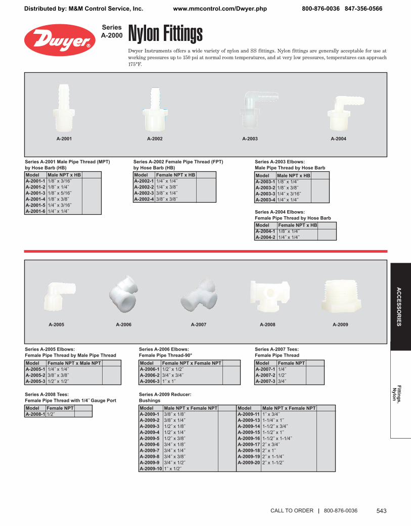
Nylon FittingsDwyer Instruments offers a wide variety of nylon and SS fittings. Nylon fittings are generally acceptable for use atworking pressures up to 150 psi at normal room temperatures, and at very low pressures, temperatures can approach175°F.
Series A-2001 Male Pipe Thread (MPT)by Hose Barb (HB)Model A-2001-1A-2001-2A-2001-3A-2001-4A-2001-5A-2001-6
Model A-2002-1A-2002-2A-2002-3A-2002-4
Series A-2002 Female Pipe Thread (FPT) by Hose Barb (HB)
Series A-2003 Elbows: Male Pipe Thread by Hose Barb
Series A-2004 Elbows: Female Pipe Thread by Hose Barb
Model A-2003-1A-2003-2A-2003-3A-2003-4
Model A-2004-1A-2004-2
Model A-2005-1A-2005-2A-2005-3
Series A-2005 Elbows: Female Pipe Thread by Male Pipe Thread
Model A-2006-1A-2006-2A-2006-3
Series A-2006 Elbows: Female Pipe Thread-90°
Model A-2007-1A-2007-2A-2007-3
Series A-2007 Tees: Female Pipe Thread
Model A-2008-1
Series A-2008 Tees: Female Pipe Thread with 1/4˝ Gauge Port
Model A-2009-1A-2009-2A-2009-3A-2009-4A-2009-5A-2009-6A-2009-7A-2009-8A-2009-9A-2009-10
Model A-2009-11A-2009-13A-2009-14A-2009-15A-2009-16A-2009-17A-2009-18A-2009-19A-2009-20
Series A-2009 Reducer: Bushings
A-2001 A-2002 A-2004
A-2005 A-2008A-2006 A-2007
A-2003
A-2009
SeriesA-2000
CALL TO ORDER | 800-876-0036
Male NPT x HB1/8˝ x 3/16˝1/8˝ x 1/4˝1/8˝ x 5/16˝1/8˝ x 3/8˝1/4˝ x 3/16˝1/4˝ x 1/4˝
Female NPT x HB1/4˝ x 1/4˝1/4˝ x 3/8˝3/8˝ x 1/4˝3/8˝ x 3/8˝
Male NPT x HB1/8˝ x 1/4˝1/8˝ x 3/8˝1/4˝ x 3/16˝1/4˝ x 1/4˝
Female NPT x HB1/8˝ x 1/4˝1/4˝ x 1/4˝
Female NPT x Male NPT1/4˝ x 1/4˝3/8˝ x 3/8˝1/2˝ x 1/2˝
Female NPT x Female NPT1/2˝ x 1/2˝3/4˝ x 3/4˝1˝ x 1˝
Female NPT1/4˝1/2˝3/4˝
Female NPT1/2˝
Male NPT x Female NPT3/8˝ x 1/8˝3/8˝ x 1/4˝1/2˝ x 1/8˝1/2˝ x 1/4˝1/2˝ x 3/8˝3/4˝ x 1/8˝3/4˝ x 1/4˝3/4˝ x 3/8˝3/4˝ x 1/2˝1˝ x 1/2˝
Male NPT x Female NPT1˝ x 3/4˝1-1/4˝ x 1˝1-1/2˝ x 3/4˝1-1/2˝ x 1˝1-1/2˝ x 1-1/4˝2˝ x 3/4˝2˝ x 1˝2˝ x 1-1/4˝2˝ x 1-1/2˝
543_Layout 1 7/15/14 9:31 AM Page 543
Distributed by: M&M Control Service, Inc. www.mmcontrol.com/Dwyer.php 800-876-0036 847-356-0566

DWYER INSTRUMENTS, INC.544
Pneu
mat
ic V
alve
sA
CC
ESSO
RIE
S
Model A-2011-1A-2011-2A-2011-3A-2011-4
Series A-2011 Nipples: Male Pipe Thread by Male Pipe Thread
Model A-2012-1A-2012-2A-2012-3
Series A-2012 Couplings: Female Pipe Thread
Model A-2013-1A-2013-2
Series A-2013 Elbows: Hose Barb
Model A-2014-1A-2014-2
Series A-2014 Hose Menders without Center Stop
Series A-2015 Hose Menders with Center StopModel A-2015-1A-2015-2
Series A-2016 Tees: Hose BarbModel A-2016-1A-2016-2
Series A-2017 Tees: Male Pipe Thread by Hose BarbModel A-2017-1A-2017-2A-2017-3A-2017-4
A-2011 A-2012 A-2013
A-2014 A-2015 A-2016 A-2017
A-2010
Model A-2010-1A-2010-2A-2010-3A-2010-4A-2010-5A-2010-6A-2010-7
Series A-2010 Reducing Nipples: Male Pipe Thread
Nylon FittingsSeriesA-2000
Quick Connect Pneumatic ValvesSeriesA-4000
ModelA-4002-0A-4002-1A-4002-2A-4002-3A-4002-4A-4002-5A-4002-6A-4002-7
Series A-4002 Valves: Tubing to Male NPT
SPECIFICATIONSService: Air (no other gases or liquids).Wetted Materials: Polyurethane, polyethylene and nylon.Pressure Limits: -29.5 in Hg (-750 mm Hg) to 150 psi (10 bar).Temperature Limits: 32 to 140°F (0 to 60°C).Weight: A-4002: 1 oz (28 g); A-4022: 1.3 oz (36 g).
A-4002HAND VALVE
2-5/16 [58.7]
1-9/16[39.8]
11/16 [17.4]
*Please contact factory for metric and alternate connection sizes.
ModelA-4022-2A-4022-4
Series A-4022 Valves: Tubing to Male NPT with Extension
*Please contact factory for metric and alternate connection sizes.
A-4022
OPEN
OPEN
HAND VALVE
MODELS WITH EXTENSION2-13/16 [71.4]
Tubing (O.D.) x NPT5/32˝ x 1/8˝5/32˝ x 1/4˝1/4˝ x 1/8˝1/4˝ x 1/4˝5/16˝ x 1/8˝5/16˝ x 1/4˝3/8˝ x 1/8˝3/8˝ x 1/4˝
Tubing (O.D.) x NPT with Extension1/4˝ x 1/8˝ with Extension5/16˝ x 1/8˝ with Extension
Male NPT x Male NPT1/8˝ x 1/8˝1/4˝ x 1/4˝3/8˝ x 3/8˝1/2˝ x 1/2˝
Female NPT x Female NPT1/2˝ x 1/2˝3/4˝ x 3/4˝1˝ x 1˝
HB x HB1/4˝ x 1/4˝3/8˝ x 1/4˝
HB x HB1/4˝ x 3/16˝5/16˝ x 5/16˝
HB x HB1/8˝ x 1/8˝1/4˝ x 1/4˝
HB(1) x HB(2&3)1/4˝ x 1/4˝1/4˝ x 3/8˝
Male NPT (1) x HB (2&3)1/8˝ x 1/4˝1/4˝ x 1/4˝1/4˝ x 3/8˝1/4˝ x 1/2˝
Male NPT x Male NPT1/4˝ x 1/8˝3/8˝ x 1/8˝3/8˝ x 1/4˝1/2˝ x 1/4˝1/2˝ x 3/8˝3/4˝ x 3/8˝3/4˝ x 1/2˝
544_Layout 1 7/21/14 10:45 AM Page 544
Distributed by: M&M Control Service, Inc. www.mmcontrol.com/Dwyer.php 800-876-0036 847-356-0566

545
Pneumatic Fittings
AC
CESSO
RIES
Quick Connect Pneumatic FittingsSeriesA-3000
SPECIFICATIONSService: Air (no other gases or liquids).Pressure Limits: -29.5 in Hg (-750 mm Hg) to 150 psi (10.3 bar).Temperature Limits: 32 to 140°F (0 to 60°C).Wetted Materials: Polyurethane, polyethylene and nylon.Weight: 0.4 oz (11 g) to 0.7 oz (19 g).
ModelA-3025-0A-3025-1A-3025-2A-3025-3
A-3025 & A-3029 A-3026
A-3028
Series A-3025 Fittings:Quick Coupling Straight
ModelA-3026-0A-3026-1A-3026-2A-3026-3
Series A-3026 Fittings:Quick Coupling 90 Degree
ModelA-3027-0A-3027-1A-3027-2A-3027-3
Series A-3027 Fittings:3 Way Quick Coupling
ModelA-3028-0A-3028-1A-3028-2A-3028-3
Series A-3028 Fittings:4 Way Quick Coupling
ModelA-3029-0A-3029-1A-3029-2A-3029-3
Series A-3029 Fittings:Quick Coupling Straight Adapter
ModelA-3030-0A-3030-1A-3030-2A-3030-3
Series A-3030 Fittings:3 Way Quick Coupling Adapter
*Please contact factory for metric sizes.
A-3027 & A-3030
SPECIFICATIONSService: Air (no other gases or liquids).Pressure Limits: -29.5 in Hg (-750 mm Hg) to 150 psi (10.3 bar).Temperature Limits: 32 to 140°F (0 to 60°C).Wetted Materials: Polyurethane, polyethylene and nylon.Weight: 0.4 oz (11 g) to 0.7 oz (19 g).
COUPLINGSIZE
ACOUPLING
SIZE
BModelA-3025A-3029-0-1-2-3
A1.33 [33.8]1.38 [35]1.53 [38.9]1.62 [41.1]
B0.45 [11.5]0.55 [14]0.57 [14.6]0.69 [17.6]
COUPLING SIZE A MOUNTING
HOLE
COUPLINGSIZE
B
MOUNTING HOLES
B
A
COUPLINGSIZE
COUPLINGSIZE
B
A
COUPLINGSIZE
MOUNTINGHOLES
ModelA-3026-0A-3026-1A-3026-2A-3026-3
A0.93 [23.7]1.09 [27.8]1.20 [30.6]1.33 [33.8]
B0.93 [23.7]1.09 [27.8]1.20 [30.6]1.33 [33.8]
ModelA-3027A-3030-0-1-2-3
A1.49 [37.8]1.64 [41.6]1.83 [46.6]1.98 [50.4]
B0.97 [23.7]1.09 [27.8]1.20 [30.6]1.33 [33.8]
ModelA-3028-0A-3028-1A-3028-2A-3028-3
A1.49 [37.8]1.64 [41.6]1.83 [46.6]1.98 [50.4]
B1.49 [37.8]1.64 [41.6]1.83 [46.6]1.98 [50.4]
CALL TO ORDER | 800-876-0036
Price$3.603.603.604.10
Coupling (O.D.) x Coupling (O.D.)3/16˝ x 3/16˝1/4˝ x 1/4˝5/16˝ x 5/16˝3/8˝ x 3/8˝
Coupling (O.D.) x Coupling (O.D.)3/16˝ x 3/16˝1/4˝ x 1/4˝5/16˝ x 5/16˝3/8˝ x 3/8˝
Coupling (O.D.)3/16˝1/4˝5/16˝3/8˝
Coupling (O.D.)3/16˝1/4˝5/16˝3/8˝
Coupling (O.D.) x Coupling (O.D.)1/4˝ x 3/16˝5/16˝ x 1/4˝3/8˝ x 1/4˝3/8˝ x 5/16˝
Coupling (O.D.)1/4˝ x 1/4˝ x 3/16˝5/16˝ x 5/16˝ x 1/4˝3/8˝ x 3/8˝ x 1/4˝3/8˝ x 3/8˝ x 5/16˝
545_Layout 1 7/15/14 9:29 AM Page 545
Distributed by: M&M Control Service, Inc. www.mmcontrol.com/Dwyer.php 800-876-0036 847-356-0566

DWYER INSTRUMENTS, INC.546
Pneu
mat
ic F
ittin
gsA
CC
ESSO
RIE
S
Quick Connect Pneumatic FittingsSeriesA-3000
ModelA-3021-1A-3021-2A-3021-3A-3021-4A-3021-5A-3021-6
A-3021 A-3022
Series A-3021 Fittings:Quick Coupling to NPT Straight
ModelA-3022-1A-3022-2A-3022-3A-3022-4A-3022-5A-3022-6
Series A-3022 Fittings:Quick Coupling to NPT 90 Degree
SPECIFICATIONSService: Air (no other gases or liquids).Wetted Materials: Polyurethane, polyethylene and nylon. Note: (A-3021 nickelplated brass).Pressure Limits: -29.5 in Hg (-750 mm Hg) to 150 psi (10.3 bar).Temperature Limits: 32 to 140°F (0 to 60°C).Weight: 0.4 oz (11 g) to 0.7 oz (19 g).
HEX SIZE
A
HEX SIZEA
B
ModelA-3021-1A-3021-2A-3021-3A-3021-4A-3021-5A-3021-6
A0.79 [20.3]0.86 [21.8]0.82 [20.9]0.88 [22.4]1.01 [25.7]0.95 [24.2]
ModelA-3022-1A-3022-2A-3022-3A-3022-4A-3022-5A-3022-6
A0.98 [24.9]1.02 [25.9]1.09 [27.7]1.13 [28.8]1.23 [31.3]1.26 [32]
B1.26 [32]1.30 [33]1.41 [35.8]1.45 [36.8]1.53 [38.9]1.57 [39.9]
A-3023 A-3024
*Please contact factory for metric sizes.
ModelA-3023-1A-3023-2A-3023-3A-3023-4A-3023-5A-3023-6
Series A-3023 Fittings:3 Way-Quick Coupling by Quick Coupling to NPT
ModelA-3024-1A-3024-2A-3024-3A-3024-4A-3024-5A-3024-6
Series A-3024 Fittings:3 Way-Quick Coupling by NPT to Quick Coupling
SPECIFICATIONSService: Air (no other gases or liquids).Wetted Materials: Polyurethane, polyethylene and nylon.Pressure Limits: -29.5 in Hg (-750 mm Hg) to 150 psi (10.3 bar).Temperature Limits: 32 to 140°F (0 to 60°C).Weight: 0.4 oz (11 g) to 0.7 oz (19 g).
HEX SIZE
A
B
HEX SIZE
A
B
*Please contact factory for metric sizes.
ModelA-3023-1A-3023-2A-3023-3A-3023-4A-3023-5A-3023-6
A1.31 [33.3]1.35 [34.3]1.43 [36.3]1.47 [37.3]1.53 [38.9]1.57 [39.9]
B1.49 [37.8]1.49 [37.8]1.64 [41.6]1.64 [41.6]1.83 [46.6]1.83 [46.6]
ModelA-3024-1A-3024-2A-3024-3A-3024-4A-3024-5A-3024-6
A1.83 [46.4]1.87 [47.4]1.97 [50.1]2.01 [51.1]2.16 [54.9]2.20 [55.9]
B1.02 [25.9]1.06 [26.9]1.09 [27.8]1.13 [28.8]1.23 [31.3]1.26 [32]
Coupling (O.D.) x NPT1/4˝ x 1/8˝1/4˝ x 1/4˝5/16˝ x 1/8˝5/16˝ x 1/4˝3/8˝ x 1/8˝3/8˝ x 1/4˝
Coupling (O.D.) x NPT1/4˝ x 1/8˝1/4˝ x 1/4˝5/16˝ x 1/8˝5/16˝ x 1/4˝3/8˝ x 1/8˝3/8˝ x 1/4˝
Coupling (O.D.) x NPT x Coupling (O.D.)1/4˝ x 1/4˝ x 1/8˝1/4˝ x 1/4˝ x 1/4˝5/16˝ x 5/16˝ x 1/8˝5/16˝ x 5/16˝ x 1/4˝3/8˝ x 3/8˝ x 1/8˝3/8˝ x 3/8˝ x 1/4˝
Coupling (O.D.) x Coupling (O.D.) x NPT1/4˝ x 1/4˝ x 1/8˝1/4˝ x 1/4˝ x 1/4˝5/16˝ x 5/16˝ x 1/8˝5/16˝ x 5/16˝ x 1/4˝3/8˝ x 3/8˝ x 1/8˝3/8˝ x 3/8˝ x 1/4˝
546_Layout 1 7/15/14 9:28 AM Page 546
Distributed by: M&M Control Service, Inc. www.mmcontrol.com/Dwyer.php 800-876-0036 847-356-0566

547
Gage Tubing
AC
CESSO
RIES
Gage Tubing Accessories
Gage TubingMODELS
A-200 A-201/A-202
A-203 A-204
A-225
A-220A-221
A-222
A-223 A-223P
A-210/A-211
Norprene® is a registered trademark of Saint-Gobain Adhesives, Inc.
A-224
CALL TO ORDER | 800-876-0036
A-200, Norprene® tubing is useful in a wide range of temperatures from -75 to275°F (-60 to 135°C) and will not weaken after long term exposure to heat andozone.
A-200-1, 3/16˝ ID x 5/16˝ OD, 13 psi maximum pressure @ 73°F (90 kPa @ 23°C); 50´ . . . . . . . . . . . . . . . . . . . . . . . . . . . . . . . . . . . . . . . . . . . . . . . .A-200-2, 1/4˝ ID x 3/8˝ OD, 10 psi maximum pressure @ 73°F (69 kPa @ 23°C); 50´ . . . . . . . . . . . . . . . . . . . . . . . . . . . . . . . . . . . . . . . . . . . . . . . . . . . . . . .
A-201, Rubber latex tubing has less tendency to kink in storage and occupies lessspace, thus is best for portable work. 3/16˝ ID, 9´ length . . . . . . . . . . . . . . . .
A-202, Rubber latex tubing. 3/16˝ ID, lengths to 50´ . . . . . . . . . . . . . . . ..
A-203, Clear PVC tubing is easily inspected and is therefore best for testapplications where a possibility of fluid entering the tubing exists.1/8˝ ID x 1/4˝ OD, lengths to 100´; 60 psi max. pressure @ 73°F (22°C) .
A-221, Clear flexible vinyl tubing is easily inspected, and is therefore best for testapplications where a possibility of fluid entering the tubing exists. 1/8˝ ID x 3/16˝OD, lengths to 500´; 40 psi maximum pressure @ 165°F (276 kPa @ 74°C) . . . . . . . . . . . . . . . . . . . . . . . . . . . . . . . . . . . . . .
A-225, Flexible double column plastic tubing is used with Mark II manometers andthe Wind Speed Indicator. Light gray with red color code stripe. 1/8˝ ID, lengths to750´ . . . . . . . . . . . . . . . . . . . . . . . . . . . . . . . . . . . . . . . . . . . . . . . . . . . . . . ..
A-204, Flexible colored vinyl tubing is quickly distinguishable in applications wheremore than one line is required aiding installation. 3/16˝ ID x 5/16˝ OD, lengths to500´; 45 psi maximum pressure @ 165°F (310 kPa @ 74°C).
A-204-A, Opaque Red . . . . . . . . . . . . . . . . . . . . . . . . . . . . . . . . . . . . . . .A-204-B, Opaque Blue . . . . . . . . . . . . . . . . . . . . . . . . . . . . . . . . . . . . . .A-204-C, Opaque White . . . . . . . . . . . . . . . . . . . . . . . . . . . . . . . . . . . . .A-204-D, Opaque Black . . . . . . . . . . . . . . . . . . . . . . . . . . . . . . . . . . . . . .
A-220, Clear flexible vinyl tubing is easily inspected, and is therefore best for testapplications where a possibility of fluid entering the tubing exists. 3/16˝ ID x 5/16˝OD, lengths to 500´; 45 psi maximum pressure @ 73°F (310 kPa @ 23°C) . . . . . . . . . . . . . . . . . . . . . . . . . . . . . . . . . . . . . . .
A-222, Clear flexible vinyl tubing is easily inspected, and is therefore best for testapplications where a possibility of fluid entering the tubing exists. .240˝ ID x .375˝OD, lengths to 500´; 35 psi maximum pressure @73°F (240 kPa @ 23°C) . . . . . . . . . . . . . . . . . . . . . . . . . . . . . . . . . . . . . ..
A-223, Black polyethylene tubing offers long life, great stability and resistance tocorrosion. 1/8˝ ID x 1/4˝ OD, 10´ length; 200 psi maximum @140°F (1379 kPa @ 60°C) . . . . . . . . . . . . . . . . . . . . . . . . . . . . . . . . . . . . . . .
A-224, Black nylon tubing is recommended for high temperature and pressureapplications. Lengths to 1312 ft; -40 to 248°F (-40 to 120°C).
A-224-A, 0.23˝ ID x 5/16˝ OD; 362 psi (2500 kPa) working pressure . . .A-224-B, 0.256˝ ID x 3/8˝ OD, 406 psi (2800 kPa) working pressure . . .
A-223P, Black plenum fire retardent polyethylene tubing meets NFPA standard 90Afor installation in air-conditioning and ventilating plenum spaces; also used inbuilding automation systems. Lengths to 500´, 100 psig maximum pressure @75°F (689 kPa @ 24°C).
A-223P-1, .17˝ ID x .25˝ OD . . . . . . . . . . . . . . . . . . . . . . . . . . . . . . . . . .A-223P-2, 1/4˝ ID x 3/8˝ OD . . . . . . . . . . . . . . . . . . . . . . . . . . . . . . . . . .
A-210, Aluminum tubing is recommended for permanent installations. 1/4˝ OD, 5´ length, 500 psi maximum pressure @ 200°F (3447 kPa @ 93°C) . . . . . .
A-211, Aluminum tubing, 1/4˝ OD, 50´ length, 500 psi maximum pressure @ 200°F(3447 kPa @ 93°C) . . . . . . . . . . . . . . . . . . . . . . . . . . . . . . . . . . . . . . . . . ..
547_Layout 1 7/15/14 9:27 AM Page 547
Distributed by: M&M Control Service, Inc. www.mmcontrol.com/Dwyer.php 800-876-0036 847-356-0566

DWYER INSTRUMENTS, INC.548
Stat
ic P
ress
ure
Sens
ors
AC
CES
SOR
IES
Static Pressure Tips
SPECIFICATIONSSizes: 4˝ (101 mm), 6˝ (152 mm), 8˝ (203 mm).Materials: 304 SS sensor tube, 303 SS hose barb, 430 SS flange.Connection: Barb connection for use with 3/16˝ ID tubing.
Flange View
A-489
A-493
4˝
The Stainless Steel Static Pressure Tips are used to measure static pressures inducts or rooms. They are to be connected to differential pressure switches and transmitters.Two static sensors are used in applications where differential pressure is required acrossa filter or coil. These sensors include a mounting flange with integral rubber gasket andtwo screws for simplifying mounting on a duct.
A-308 A-414 A-307
A-301
A-302
A-303
Designed for simplified installation, these are easy to install, inexpensive, andprovides accurate static pressure sensing in smooth air at velocities up to 1500 FPM.
These static pressure tips are ideal for applications such as sensing the staticpressure drop across industrial air filters and refrigerant coils. Here the probability of air turbulence requires that the pressure sensing openings be located away from theduct walls to minimize impingement and aspiration, and thus ensure accuratereadings. For a permanent installation of this type, the Dwyer No. A-301 or A-302Static Pressure Tip is used. It senses static pressure through radially-drilled holesnear the tip and can be used in air flow velocities up to 12,000 FPM. The angled tipsshown have 4˝ insertion depth. Each has four radially drilled .040˝ sensing holes. Allexcept Model A-303 mount in 3/8˝ hole in duct. For portable use, a magnet holds No.A-303 in place.
A-305 low resistance Static Pressure Tip is designed for use in dust-laden air andfor rapid response applications. It is recommended where a very low actuationpressure is required for a pressure switch or indicating gage — or where responsetime is critical. A-305
A-491
6˝
A-302F-A A-302F-B
A-302F-C8˝
A-306-A
A-302F-A, 4˝ Hook style SS Static Pressure Tip with mounting flange . . . . . .A-302F-B, 6˝ Hook style SS Static Pressure Tip with mounting flange . . . . . .A-302F-C, 8˝ Hook style SS Static Pressure Tip with mounting flange . . . . . .A-489, 4˝ Straight SS Static Pressure Tip with mounting flange . . . . . . . . . . . .A-491, 6˝ Straight SS Static Pressure Tip with mounting flange . . . . . . . . . . . .A-493, 8˝ Straight SS Static Pressure Tip with mounting flange . . . . . . . . . . . .
A-307, Static Pressure Fitting, for 1/4˝ metal tubing connection . . . . . . . . . . .A-307-SS, same as above in Stainless Steel . . . . . . . . . . . . . . . . . . . . . . . . .A-308, Static Pressure Fitting, for 3/16˝ and 1/8˝ ID plastic or rubber tubing . .A-414, SS Clean Room Pressure Sensor . . . . . . . . . . . . . . . . . . . . . . . . . . . .
A-301, Static Pressure Tip, for 1/4˝ metal tubing connection . . . . . . . . . . . . .A-301-A, Static Pressure Tip, same as A-301 with 6˝ insertion depth . . . . . . .A-301-B, Static Pressure Tip, same as A-301 with 8˝ insertion depth . . . . . . .A-301-C, Static Pressure Tip, same as A-301 with 12˝ insertion depth . . . . . .A-301-SS, same as A-301 in Stainless Steel . . . . . . . . . . . . . . . . . . . . . . . . .A-302, Static Pressure Tip, for 3/16˝ and 1/8˝ ID plastic or rubber tubing . . . . .A-302-A, Static Pressure Tip, same as A-302 with 6˝ insertion depth . . . . . . .A-303, Portable Static Pressure Tip, for 3/16˝ ID rubber or plastic tubing with 4˝insertion . . . . . . . . . . . . . . . . . . . . . . . . . . . . . . . . . . . . . . . . . . . . . . . . . . . . . . .
A-305, Static Pressure Tip, low resistance application, furnished with two (2) hex jamnuts and two (2) mounting washers for duct mounting and with 1/8˝ NPT pipe threadfor pressure connection . . . . . . . . . . . . . . . . . . . . . . . . . . . . . . . . . . . . . . . . .A-305-SS, same as A-305 in Stainless Steel . . . . . . . . . . . . . . . . . . . . . . . . .A-306, Outdoor static pressure sensor. Provides average outdoor pressure signal forreference in building pressurization applications. Includes sensor, 50´ vinyl tubing,mounting bracket and hardware. Red Sensor . . . . . . . . . . . . . . . . . . . . . . . . .A-306-A, Outdoor static pressure sensor. Provides average outdoor pressure signalfor reference in building pressurization applications. Includes sensor, 50´ vinyltubing, mounting bracket and hardware. Gray Sensor . . . . . . . . . . . . . . . . . .
548_Layout 1 7/15/14 9:26 AM Page 548
Distributed by: M&M Control Service, Inc. www.mmcontrol.com/Dwyer.php 800-876-0036 847-356-0566

549
Static Pressure SensorsA
CC
ESSOR
IES
Static Pressure Accessories
A-417A
A-419A
A-420A
A-421
Surge Damper
A-465
A-418E A-418N
CALL TO ORDER | 800-876-0036
The A-465 Static Pressure Pick-Up provides a clean solution for sensing spacepressure. The sensor can be mounted on sheetrock walls, single gang electricalboxes, or on ceiling tiles. Molded from ABS plastic, the A-465 provides an integralbarb fitting and includes tubing, mounting screws and anchors. . . . . . . . . . . .
Model A-417A, Static Pressure Pickup. For use in clean rooms, 60 micron filter picksup static pressure. Stainless steel wall plate fits 2˝ x 4˝ electrical box. Sealed withfoam gasket, screws included. Barbed brass fitting holds 1/8˝ to 3/16˝ ID tubing. . . . . . . . . . . . . . . . . . . . . . . . . . . . . . . . . . . . . . . . . . . . . . . . . . . . . . . . . . . . . . . . .
Models A-418E & A-418N, Static Pressure Pickup. Room mount with plasticenclosure fits 2˝ x 4˝ electrical box. Fine mesh screen hides static pressure pickupport. Clean connection to 1/8˝ to 3/16˝ ID tubing and pressure sensor. Sealed withfoam gasket, screws included . . . . . . . . . . . . . . . . . . . . . . . . . . . . . . . . . . . . . .
Model A-419A, Static Pressure Pickup Ceiling Mount. Plate rests on top of standard3/4˝ thick ceiling tile while 60 micron filter faces down through 5/8˝ hole in tile. Filteris barely noticeable in room being monitored. Unit mounts to junction box. Barbedbrass fitting holds 1/8˝ to 3/16˝ ID tubing. . . . . . . . . . . . . . . . . . . . . . . . . . . . . . .
Model A-420A, Static Pressure Pickup for Roof or Outside Mount. Reduces effectsof wind gusts to keep pressure readings stable when plate is parallel to ground.Structure withstands harsh environmental elements. Structure is 3-1/4˝ across and2-3/8˝ deep. EMT Conduit fitting is 1/2˝. Pressure connection is brass barbed fittingfor 1/8˝ and 3/16˝ ID tubing. . . . . . . . . . . . . . . . . . . . . . . . . . . . . . . . . . . . . . . .
Model A-421, Static Pressure Tip measures duct static air pressure. Assemblyincludes 6˝ probe, silicon rubber hose, and screws. Built-in surge damper ensuresstable readings on pressure sensor. Pressure spike reducer can be added to end oftube to further smooth over pressure fluctuations. . . . . . . . . . . . . . . . . . . . . . .
549_Layout 1 7/15/14 9:25 AM Page 549
Distributed by: M&M Control Service, Inc. www.mmcontrol.com/Dwyer.php 800-876-0036 847-356-0566

DWYER INSTRUMENTS, INC.550
Mis
cella
neou
sA
cces
sorie
sA
CC
ESSO
RIE
S
Fittings – Filters
A-346
A-339
A-334
A-330 A-331 A-332 A-333
A-324 A-326 A-327, A-328 A-329
A-336 A-337 A-338
A-340 A-342 A-345
A-349 A-391 A-392 A-398
ACCESSORIES
Valves – Connectors
A-310A A-310B A-311 A-312
A-355 A-365
A-315 A-316 A-317 A-318
A-319 A-321 A-322
A-5000
A-323, Elbow Compression Fitting, brass 1/8˝ NPT to 1/4˝ metal tubing . . . . . . . .A-324, Compression Fitting, brass 1/8˝ NPT to 1/4˝ metal tubing . . . . . . . . . . . . . .A-326, Compression Fitting, brass 1/8˝ NPT to 3/8˝ tubing . . . . . . . . . . . . . . . . . . .A-327, 5/16˝ Nylon Tube Union . . . . . . . . . . . . . . . . . . . . . . . . . . . . . . . . . . . . . . . .A-328, 1/4˝ Nylon Tube Union . . . . . . . . . . . . . . . . . . . . . . . . . . . . . . . . . . . . . . . . .A-329, 1/8˝ NPT Close Coupled Street Ell, Brass . . . . . . . . . . . . . . . . . . . . . . . . . .A-330, 1/8˝ Pipe Plug, socket hex, plated steel . . . . . . . . . . . . . . . . . . . . . . . . . . . .A-331, 1/8˝ NPT Filter Vent Plug, nylon and sintered metal . . . . . . . . . . . . . . . . . . .A-332, Bushing, brass, 1/8˝ to 1/4˝ NPT . . . . . . . . . . . . . . . . . . . . . . . . . . . . . . . . .A-333, Bushing, brass, 1/8˝ to 1/2˝ NPT . . . . . . . . . . . . . . . . . . . . . . . . . . . . . . . . .A-334, Close Nipple, brass, 1/8˝ NPT . . . . . . . . . . . . . . . . . . . . . . . . . . . . . . . . . . .A-336, 90° Street L, brass, 1/8˝ NPT . . . . . . . . . . . . . . . . . . . . . . . . . . . . . . . . . . . .A-337, Coupling, brass, 1/8˝ NPT . . . . . . . . . . . . . . . . . . . . . . . . . . . . . . . . . . . . . .A-338, Servel Adapter, brass 3/8˝ and 5/16˝ N.F. Threads for gas appliances to 1/8˝ and3/16˝ ID rubber or plastic tubing . . . . . . . . . . . . . . . . . . . . . . . . . . . . . . . . . . . . . . .A-339, Adapter, brass, 1/8˝ NPT to 3/16˝ rubber and 1/8˝ ID plastic tubing . . . . . . .A-340, Adapter, nylon, 1/8˝ NPT to 3/16˝ ID rubber or 1/4˝ plastic tubing . . . . . . . .A-342, “T” Assembly, plastic, for 3/16˝ ID rubber or 1/4˝ plastic tubing . . . . . . . . .A-343, “T” Assembly, plastic, for 3/16˝ plastic tubing . . . . . . . . . . . . . . . . . . . . . . . .A-343-1, “T” Assembly, plastic, for 1/8˝ ID plastic tubing . . . . . . . . . . . . . . . . . . . . .A-344, Terminal Tube, Brass 1/4˝ diameter tube, 8˝ L (not shown) . . . . . . . . . . . . .A-345, Flange, aluminum with gasket and sheet metal screws, 1/8˝ NPT . . . . . . . .A-346, “T” Compression Fitting, brass, 1/4˝ metal tubing . . . . . . . . . . . . . . . . . . . . .A-349, Reducer, brass, 1/4˝ female NPT to 1/8˝ male NPT. . . . . . . . . . . . . . . . . . . .A-385, 1/2˝ Plastic Hole Plugs 20/bag . . . . . . . . . . . . . . . . . . . . . . . . . . . . . . . . . . .A-386, 5/16˝ Metal Hole Plugs 20/bag . . . . . . . . . . . . . . . . . . . . . . . . . . . . . . . . . . .A-391, Line Filter for Capsuhelic® gage,1/4˝ female NPT X 1/4˝ male NPT . . . . . .A-392, Line Filter for Magnehelic® gage, 1/8˝ female NPT x 1/8˝ male NPT. . . . . .A-398, Probe Extension Adapter for series 640 air velocity transmitter. Brass, 1/2˝female NPT x 5/16˝ compression . . . . . . . . . . . . . . . . . . . . . . . . . . . . . . . . . . . . . .
Instrument valves for permanent installation. They mount in part A-316, A-317, type Cmanometer connections or Magnehelic® gage and connect to metal tubing or 1/8˝ pipe.A-310A, 3-Way Vent Valve, plastic, 1/8˝ NPT to 1/4˝ metal tubing. Positions are: (1)Line: Gage connected to pressure source. (2) Off: Both gage and connection to pressuresource closed. (3) Vent: Gage vented to atmosphere and connection to pressure sourceclosed. 80 psi rating. Replaces former model A310 (brass) . . . . . . . . . . . . . . . .A-310B, same as A-310A but with 10 psi rating . . . . . . . . . . . . . . . . . . . . . . . . . .A-311, Shut Off Valve, brass, 1/8˝ NPT to 1/8˝ NPT . . . . . . . . . . . . . . . . . . . . . .A-312, Shut Off Valve, brass, 1/8˝ NPT to 1/4˝ metal tubing . . . . . . . . . . . . . . . .A-5001-1, PVC 1/8˝ hose barb inlet x 1/8˝ hose barb outlet x 1/8˝ hose barb outlet (125psi maximum) . . . . . . . . . . . . . . . . . . . . . . . . . . . . . . . . . . . . . . . . . . . . . . . . . . .A-5002-2, PVC 1/4˝ hose barb inlet x 1/4˝ hose barb outlet x 1/4˝ hose barb outlet (125psi maximum) . . . . . . . . . . . . . . . . . . . . . . . . . . . . . . . . . . . . . . . . . . . . . . . . . . .A-5003-3, PVC 1/8˝ female NPT inlet x 1/8˝ female NPT outlet x 1/8˝ female NPT outlet(125 psi maximum) . . . . . . . . . . . . . . . . . . . . . . . . . . . . . . . . . . . . . . . . . . . . . . .A-5003-5, PVC 1/8˝ male NPT inlet x 1/8˝ female NPT outlet x 1/8˝ female NPT outlet(125 psi maximum) . . . . . . . . . . . . . . . . . . . . . . . . . . . . . . . . . . . . . . . . . . . . . . .A-5004-4, PVC 1/4˝ female NPT inlet x 1/4˝ female NPT outlet x 1/4˝ female NPT outlet(125 psi maximum) . . . . . . . . . . . . . . . . . . . . . . . . . . . . . . . . . . . . . . . . . . . . . . .A-5004-6, PVC 1/4˝ male NPT inlet x 1/4˝ female NPT outlet x 1/4˝ female NPT outlet(125 psi maximum) . . . . . . . . . . . . . . . . . . . . . . . . . . . . . . . . . . . . . . . . . . . . . . .A-5005-3, PVC 1/8˝ female NPT inlet x 1/8˝ male NPT outlet x 1/8˝ male NPT outlet (125psi maximum) . . . . . . . . . . . . . . . . . . . . . . . . . . . . . . . . . . . . . . . . . . . . . . . . . . .A-5006-4, PVC 1/4˝ female NPT inlet x 1/4˝ male NPT outlet x 1/4˝ male NPT outlet (125psi maximum) . . . . . . . . . . . . . . . . . . . . . . . . . . . . . . . . . . . . . . . . . . . . . . . . . . .A-355, Porting Valve, acrylic plastic, 1/8˝ NPT inserts. Used for convenient indication ofpressure at two points with a single gage . . . . . . . . . . . . . . . . . . . . . . . . . . . . . . .A-365, Dual Porting Valve, acrylic plastic, 1/8˝ NPT fittings. For monitoring threepressures, two at a time, with one gage . . . . . . . . . . . . . . . . . . . . . . . . . . . . . . . .
Gage Connectors for Manometers. Molded nylon construction, threaded .786 x 27 N.S.,with O-ring seal. A-315, Gage connector, Shut off type, for 3/16˝ rubber tubing . . . . . . . . . . . . . . .A-316, Gage connector, bushing, 1/8˝ pipe thread opening . . . . . . . . . . . . . . . . .A-317, Gage connector, 1/8˝ pipe thread opening, less OD thd., for slip fit in 3/4˝ dia.opening in 250 series A.F. gages . . . . . . . . . . . . . . . . . . . . . . . . . . . . . . . . . . . . . .A-318, Gage connector 1/4˝ pipe thread opening . . . . . . . . . . . . . . . . . . . . . . . . .A-319, Flexible Red P.V.C. connector, 3/16˝ ID Rubber Tubing to 1/4˝ ID Plastic Tube for1221,1222 and 1227 Manometers . . . . . . . . . . . . . . . . . . . . . . . . . . . . . . . . . . . . . .A-321, Brass Safety Relief Valve Protects Magnehelic® or Photohelic® Gage againstover pressure due to regulator failure etc. Opens at 10 psi. Mounts in tee fitting insensing line or in unused gage port with addition of A-349 reducer. 1/4˝ male NPT (Usetwo for D.P. application) . . . . . . . . . . . . . . . . . . . . . . . . . . . . . . . . . . . . . . . . . . . . .A-322, Gage connector for 1/4˝ tubing. Slip fits in 3/4˝ opening in 250 series A.F. gages(Compression nut and ferrule not included) . . . . . . . . . . . . . . . . . . . . . . . . . . . . . . .
550_Layout 1 7/15/14 9:24 AM Page 550
Distributed by: M&M Control Service, Inc. www.mmcontrol.com/Dwyer.php 800-876-0036 847-356-0566

551
Miscellaneous
Accessories
AC
CESSO
RIES
Gage Fluids
A-101
A-103
A-104
A-102
ACCESSORIES
Miscellaneous
A-351 A-354 A-356
A-357 A-366
A-370
A-368A-362
A-371 A-395 A-497
A-397A-363
A-353A-352
A-300
A-465A-464
A-360
Optional Accessory Kits for Air Filter Switches
A-602 A-603 A-604
A-364
A-369
CALL TO ORDER | 800-876-0036
A-602, Air Filter Kit. Accessory package for using switch without a gage includes twopressure tips with integral compression fittings, two 5´ lengths of 1/4˝ aluminum tubingand two 1/8˝ NPT to 1/4˝ tubing compression fittings . . . . . . . . . . . . . . . . . . . . .A-603, ˝T˝ Kit. Accessory package for using pressure switch in conjunction with an airfilter kit equipped Magnehelic® or Series 250 AF gages. Includes two 1/8˝ NPT to 1/4˝tubing compression fittings and two compression tees. . . . . . . . . . . . . . . . . . . . .A-604, ˝T˝ Kit. Accessory package for using pressure switch in conjunction with MarkII gages includes two plastic tubing connector tees and two plastic tubing to 1/8˝ NPTadapters . . . . . . . . . . . . . . . . . . . . . . . . . . . . . . . . . . . . . . . . . . . . . . . . . . . . . . . . .
Gage fluids in the 1 oz size are furnished in unbreakable plastic dispenser type bottles.Larger sizes are supplied in plastic bottles with screw caps. CAUTION: Use only Dwyerfluids in Dwyer gages.
Red Gage Fluid, .826 sp. gr. The standard fluid for use in inclined manometers, “D” typevertical manometers and all Dwyer gages using red fluid.A-101, 1 oz. dispenser bottle . . . . . . . . . . . . . . . . . . . . . . . . . . . . . . . . . . . . . . . .A-102, 4 oz. bottle . . . . . . . . . . . . . . . . . . . . . . . . . . . . . . . . . . . . . . . . . . . . . . . . .A-103, 1 pt. bottle . . . . . . . . . . . . . . . . . . . . . . . . . . . . . . . . . . . . . . . . . . . . . . . . .A-104, 1 qt. bottle . . . . . . . . . . . . . . . . . . . . . . . . . . . . . . . . . . . . . . . . . . . . . . . . .
Blue Gage Fluid, 1.910 sp. gr. For special instruments and Mark II Models 26 and 28.A-110, 1 oz. dispenser bottle . . . . . . . . . . . . . . . . . . . . . . . . . . . . . . . . . . . . . .A-111, 1 pt. bottle . . . . . . . . . . . . . . . . . . . . . . . . . . . . . . . . . . . . . . . . . . . . . . .
Violet Gage Fluid, 1.000 sp. gr. Use in place of water if better meniscus is desired. A-120, 1 oz. dispenser bottle . . . . . . . . . . . . . . . . . . . . . . . . . . . . . . . . . . . . . . .A-121, 4 oz. bottle . . . . . . . . . . . . . . . . . . . . . . . . . . . . . . . . . . . . . . . . . . . . . . . . .A-122, 1 pt. bottle . . . . . . . . . . . . . . . . . . . . . . . . . . . . . . . . . . . . . . . . . . . . . . . .
Fluorescein Green Color Concentrate, water coloring agent. Not to be used fullstrength. Add 3/4 oz to a quart of distilled water. Contains a wetting agent to improvethe meniscus characteristics. Use in vertical manometers only. A-126, 1 oz. dispenser bottle . . . . . . . . . . . . . . . . . . . . . . . . . . . . . . . . . . . . . . . .
A-298, Flat Aluminum Bracket for flush mounting Capsuhelic® gage, 603A, 605, and3000MR . . . . . . . . . . . . . . . . . . . . . . . . . . . . . . . . . . . . . . . . . . . . . . . . . . . . . . . .A-299, Mounting Bracket, flush mount Magnehelic® gage in bracket. Bracket is thensurface mounted. Steel with gray hammertone epoxy finish . . . . . . . . . . . . . . . . .A-300, Flat Aluminum Bracket for flush mounting Magnehelic® gage . . . . . . . . . .A-351, Pinch Clamp to seal rubber tubing, as in a leakage test . . . . . . . . . . . . . . .A-352, Magneclip, slip on magnetic holder for acrylic plastic gages. Per pair . . .A-353, Magnetic Mounting. Flat style, secures to flowmeter, etc. with 6-32 machinescrew and boots insert. . . . . . . . . . . . . . . . . . . . . . . . . . . . . . . . . . . . . . . . . . . . . .A-354, Magnetic Mounting, Edge style, secures edge of acrylic manometer with 10-32machine screw and boots insert. . . . . . . . . . . . . . . . . . . . . . . . . . . . . . . . . . . . . . .A-356, Gage plug with retainer loop, polyethylene plastic. For 1/4˝ ID tubing. Slip loopover tubing OD and insert plug for seal . . . . . . . . . . . . . . . . . . . . . . . . . . . . . . . . . .A-357, Thermometer and terminal tube holder. SS wire . . . . . . . . . . . . . . . . . . . . .A-360, Aluminum DIN Rail, 1 m . . . . . . . . . . . . . . . . . . . . . . . . . . . . . . . . . . . . . . .A-362, Stand-Hang bracket, aluminum, for Minihelic® II gage . . . . . . . . . . . . . . .A-363, Scale Clamp Bar for 1221 Manometer . . . . . . . . . . . . . . . . . . . . . . . . . . . .A-364, Magnet Assembly for 1222 Manometers, 2 required (3 required for 1222-36 andM-1000). . . . . . . . . . . . . . . . . . . . . . . . . . . . . . . . . . . . . . . . . . . . . . . . . . . . . . . . . .A-366, Manometer Cleaning Brush 1/4˝ OD x 2-1/8˝ Long. Attach to wire for use . . . . . . . . . . . . . . . . . . . . . . . . . . . . . . . . . . . . . . . . . . . . . . . . . . . . . . . . . . . . . . . . . . . .
A-368, Surface mounting plate, aluminum, for Magnehelic® gage . . . . . . . . . . . . .A-369, Stand-Hang Bracket, aluminum, for Magnehelic® gage . . . . . . . . . . . . . .A-370, Mounting Bracket, Flush mount Capsuhelic® gage or Series 631B Transmitter inbracket. Bracket is then surface mounted. Steel with gray hammertone epoxy finish . . . . . . . . . . . . . . . . . . . . . . . . . . . . . . . . . . . . . . . . . . . . . . . . . . . . . . . . . . . . . . . . .
A-371, Surface Mounting Bracket. Use with Photohelic® gage on horizontal or verticalsurfaces. Also for Capsu-Photohelic® gages on vertical only . . . . . . . . . . . . . . . .A-395, Surface Mounting Bracket for Series 4000 Capsuhelic® gages. Steel with grayhammertone epoxy finish . . . . . . . . . . . . . . . . . . . . . . . . . . . . . . . . . . . . . . . . . . .A-397, Step Drill. Rugged Step Drill quickly provides true round holes in thin materials.Ideal for installation of Dwyer Pitot Tubes in sheet metal duct. No centerpunch neededto steel. Drills 3/16˝ through 1/2˝ holes in 1/16˝ increments.(Net Price, No Discount Allowed) . . . . . . . . . . . . . . . . . . . . . . . . . . . . . . . . . . . . .A-464, Flush Mount Kit for Magnehelic® gages . . . . . . . . . . . . . . . . . . . . . . . . . . .A-465, Flush Mount Space Pressure Sensor . . . . . . . . . . . . . . . . . . . . . . . . . . . . .A-497, Surface Mounting Bracket for Minihelic®II gage. Steel with satin black finish . . . . . . . . . . . . . . . . . . . . . . . . . . . . . . . . . . . . . . . . . . . . . . . . . . . . . . . . . . . . . . . . .
551_Layout 1 7/15/14 9:21 AM Page 551
Distributed by: M&M Control Service, Inc. www.mmcontrol.com/Dwyer.php 800-876-0036 847-356-0566