durham e-theses - connecting repositories cut-off thickness for waveguiding in the polymer film it...
TRANSCRIPT

Durham E-Theses
Control of gain in conjugated polymers and perylenedyes
Sheridan, A.K.
How to cite:
Sheridan, A.K. (2001) Control of gain in conjugated polymers and perylene dyes, Durham theses, DurhamUniversity. Available at Durham E-Theses Online: http://etheses.dur.ac.uk/4133/
Use policy
The full-text may be used and/or reproduced, and given to third parties in any format or medium, without prior permission orcharge, for personal research or study, educational, or not-for-profit purposes provided that:
• a full bibliographic reference is made to the original source
• a link is made to the metadata record in Durham E-Theses
• the full-text is not changed in any way
The full-text must not be sold in any format or medium without the formal permission of the copyright holders.
Please consult the full Durham E-Theses policy for further details.
Academic Support Office, Durham University, University Office, Old Elvet, Durham DH1 3HPe-mail: [email protected] Tel: +44 0191 334 6107
http://etheses.dur.ac.uk

Control of Gain in Conjugated Polymers anc. ;? erylene Dyes
Anna Sheridan
March 26, 2001
A thesis submitted to the Faculty of Science, at the University of Durham,
for the degree of Doctor of Philosophy.
The copyright of this thesis rests with the author. No quotation from it should l)c pul)lishcd in any form, including Electronic and the Internet, without the author's prior written consent. All information derived from this thesis must be acknowledged appropriately.
I 3 JUL 2001

2-001

Abstract
Control of Gain in Conjugated Polymers and Perylene
Dyes
This thesis presents an investigation into the factors which control the gain
and amplification properties in conjugated materials. Conjugated polymers
and perylene dyes are highly fluorescent, are easy to process into thin films,
and exhibit strong amplification over a broad gain bandwidth making them
ideal for use in lasers and amplifiers. The stimulated emission created when
thin films of the red emitting polymer poly(2-methoxy-5-(2'-ethylhexyloxy)-
p-phenylenvinylene) (MEH-PPV) were photoexcited with high energy laser
pulses was investigated. This was characterised by a dramatic narrowing
of the emission spectrum which has been assigned to amplified spontaneous
emission (ASE). The emission was found to have a gaussian profile and the
gain coefiicient was found to be 4 cm~^
The temperature dependence of the absorption, photoluminescence and
ASE of films of MEH-PPV was measured. The eflfect of film morphology
on the photophysical properties was investigated by using films cast from
two spinning solvents, chlorobenzene (CB) and tetrahydrofuran (THE). Film
morphology was found to greatly affect the temperature dependence.
A particularly important property is the spectral position of the ASE
and the factors which affect it . By controlling the film thickness close to
the cut-off thickness for waveguiding in the polymer film i t was shown that
the peak position of the ASE could be tuned by 31 nm. Modelling of the
waveguide modes in the polymer films was used to explain this effect. The
cut-off wavelength for each film was measured and good agreement with the
theory was found.
In order to investigate ways in which energy transfer could be used to

control the emission, two perylene dyes were used as a donor-acceptor pair
in a host matrix of poly methymethacralate (PMMA). The position of the
ASE was found to depend on the acceptor concentration. Measurements of
the photoluminescence quantum yield and time-resolved luminescence mea
surements showed that the energy transfer coefficient was 5xl0^^mol~Mm^.

Contents
1 Introduction 10 Bibliography 14
2 Theory of Conjugated Materials 17 2.1 Introduction 17
2.2 Non-degenerative Ground State Polymer 19
2.3 Photoexcitation 20
2.4 Excitons 24
2.5 Quenching Mechanisms 25
2.6 Intermolecular Interactions 26
Bibliography 29
3 Stimulated Emission 32 3.1 Introduction 32
3.2 Spontaneous and Stimulated Emission 33
3.3 Laser Operation 35
3.4 4-level Lasers 37
3.5 Mechanisms for Spectral Line-narrowing 39
3.5.1 ASE 39
3.5.2 Co-operative Emission Processes 41
3.6 Bimolecular Exciton Annihilation 41

CONTENTS 4
3.7 Analysis of Waveguide Modes 42 3.8 Summary 47
Bibliography 48
4 Experimental Techniques 51 4.1 Introduction 51
4.2 Film Preparation 52
4.2.1 Measurement of Film Thickness 53
4.3 Optical Characterisation 54
4.3.1 Absorption 54
4.3.2 Photoluminescence 55
4.4 Photoluminescence Quantum Yield 56
4.5 Measurement of PLQY 57
4.5.1 Theory 57
4.5.2 Photodiode Method 59
4.5.3 CCD method 60
4.6 Spectral Line Narrowing 61
Bibliography 66
5 Factors Controlling A S E 68 5.1 Introduction 68
5.2 PPV Derivatives 69
5.2.1 Absorption and Photoluminescence 72
5.2.2 Spectral Line Narrowing 75
5.2.3 Discussion 75
5.2.4 Aggregation 78
5.2.5 Summary 79
5.3 Factors which affect the ASE 80
5.3.1 Excitation Intensity 80
5.3.2 Angular Dependence of the Emission 83

CONTENTS 5
5.3.3 Excitation Wavelength 85 5.4 Gain and Loss Measurements 87
5.4.1 Experimental 87
5.4.2 Theory 89
5.4.3 Results 91
5.5 Conclusions • • • 94
Bibliography 96
6 Temperature and Morphology effects 100 6.1 Introduction 100
6.2 Experimental 102
6.3 Results 103
6.3.1 Photoluminescence 103
6.3.2 Absorption 106
6.3.3 Spectral Line Narrowing 106
6.3.4 CB-film data 110
6.3.5 THF-data 110
6.4 Comparison of PL and Absorption 113
6.5 Discussion 115
6.5.1 Film Morphology 115
6.5.2 PLQY 116
6.5.3 SLN Behaviour 117
6.5.4 PL and Absorption Data 118
6.6 Conclusion 118
Bibliography 120
7 Tuneability of A S E 123 7.1 Introduction 123
7.2 Theory 124
7.2.1 Spectral Location of the ASE 124

CONTENTS 6
7.2.2 ASE and Waveguiding 126
7.2.3 Modelling 126
7.3 Experimental Details 128
7.3.1 Measurement of Cut-off Wavelength 129
7.4 Results 131
7.4.1 Experimental Results 131
7.4.2 Modelling Results 131
7.4.3 Comparison of Experimental and Theoretical Data . . 136
7.5 Measurement of Cut-off Wavelength 138
7.5.1 Comparison of Theoretical and Experimental Cut-off
Data 140
7.6 Conclusions 142
Bibliography 143
8 Energy Transfer 145 8.1 Introduction 145
8.2 Theory 148
8.2.1 Energy transfer mechanisms 148
8.2.2 Non-radiative Energy Transfer 149
8.2.3 Forster (Long-range) Energy Transfer 150
8.2.4 Least Squares Fitting 153
8.3 Experimental 154
8.3.1 Film Preparation 154
8.3.2 Quantum Yield Measurements 155
8.3.3 Time-resolved Luminescence Measurements 156
8.4 Results - Evidence for Energy Transfer 156
8.4.1 Determination of Ro from the Overlap Integral . . . . 163
8.5 Results 165
8.5.1 ASE Results 165

CONTENTS 7
8.5.2 Determination of the Rate Coefficient 165 8.5.3 Method 1- Quantum Yield 167
8.5.4 Method 2-Decay Rate 169
8.6 Comparison of Method 1 and Method 2 173
8.7 Discussion 175
8.8 Conclusion 177
Bibliography 179
9 Conclusions 182
A Papers Published 1 185
B Papers Published 2 187

CONTENTS 8
Declaration The material in this thesis has not been submitted for examination for any
other degree of part thereof at the University of Durham or another insti
tution. The material in this thesis is the work of the author except where
formally acknowledged by reference.
The copyright of this thesis rests with the author. No quotation from
it should be published without their prior consent and information derived
from it acknowledged.

CONTENTS 9
Acknowledgements I would like to dedicate this thesis to my parents and thank them for their
support, encouragement and for the mobile phone.
I am very grateful to my supervisor Prof. Ifor Samuel without whose help
during the past three years, this thesis would not have been possible and to
Corning (formerlly BICC) for funding this project.
I would also like to thank everyone in the electronics, and mechanical
workshops and most of all to technicians Norman and Davey for solving
endless problems with equipment.
I am grateful to all the members of my research group especially Ben,
Alexei, LO, Mary and Nancy-Ann (for female support), John (for his hu
mour), Graham (for his laser expertise), Ma, Wang, Geetha and Phil (for
introducing me to ETgX) and all my other office-mates for their sense of
humour.
Also a huge thank you to all the friends I have made while here in Durham
especially to Deborah (for everything bright and cheerful), Ali-(-Ben (for pro
viding hotel standard accommodation and of course accurate train informa
tion), Nick (for making clocks),Frank-l-Conny and Claire (for many German
conversations), Mark and Kevin and Mary (for video evenings and food),
Roberto (for being interested in all things Jewish), Patrick (for theological
discussions and trips to the vie), to my housemates, Helen, Helen and Corinne
(for putting up with me), and to Steve and Antony for introducing me to
Seasons cafe. Finally, thanks to Phil - for providing food and friendship when
I've needed it most.

Chapter
Introduction
Although relatively new, the field of conjugated polymers is an exciting,
fast moving area, which incorporates many areas of physics, chemistry and
material science.
Conjugated materials are an important class of semi-conducting plastics.
They have an extended system of delocalised TT electrons, which gives rise to
semiconducting optical and electronic properties making electrical conduc
tion possible. In fact it was just over 10 years ago, in 1989, when organic elec
troluminescence was achieved using the conjugated polymer PPV [1]. This
discovery quickly made conjugated polymers the subject of a great deal of in
terest from companies such as Cambridge Display Technology (CDT), Uniax,
Phillips and many others, and also from many research groups throughout
the world.
Although these materials were known to be highly luminescent, early
experiments in thin films suggested that i t would not be possible to ob
serve stimulated emission [2-4] . However in 1992 Moses demonstrated
laser action in solutions of MEH-PPV (poly(2-methoxy-5-(2'-ethylhexyloxy)-
^»-phenylenvinylene)) [5]. A few years later Hide et al. observed stimulated
emission from polymers doped with titania nanoparticles [6] and the first
10

CHAPTER 1. INTRODUCTION 11
microcavity laser was fabricated using PPV [7]. I t is partly due to improvements in the quality of the polymer that these advances could be made.
The mechanism for the dramatic narrowing of the emission spectrum has
been a matter of much debate. Overwhelming evidence points to the mech
anism of amplified spontaneous emission (ASE) [6, 8-13], however there are
still those who support cooperative emission mechanisms such as superflu-
orescence (SF) and superradiance (SR) [14]. Optically pumped lasers in
various different forms have been fabricated, including microcavity lasers [7],
whispering gallery mode lasers [15] and a flexible DFB (distributed feedback)
laser [16 .
Conjugated polymers have been shown to exhibit strong ampHflcation
over a broad gain bandwidth [12, 17-19]. They are easy to process and
by chemically altering the polymers, tuning over a wide spectral range is
possible. The emission wavelength can also be controlled by using energy
transfer between a host and an acceptor [20, 21 .
For these reasons, there is hope that electrically pumped diode lasers will
be possible. One problem yet to be overcome is that of the high threshold
required for stimulated emission. The density of charge carriers injected
into the polymer must be high enough to produce a population inversion,
without damaging the polymer film. Thresholds for stimulated emission can
be reduced by introducing feedback such as in distributed feedback structures
22]. There has however been some evidence that polaron formation can
create an additional absorption in the same spectral region as the gain [23, 24]
which will quench the gain. More recent work has shown that in single
crystals of tetracene, electrically pumped laser action is possible [25 .
Conjugated polymers also have the potential to be used in amplifiers in
the communications industry. All-polymer optical fibre networks are now be
ing developed, which have the advantage that information can be transferred
quickly and efficiently. An ideal amplifier for this application would emit at
CHAPTER 1. INTRODUCTION 12
650 nm, where polymer optical fibres are transparent. Conjugated polymers are therefore ideal for this application as they are easy to incorporate into fibres, and they can demonstrate high gain at suitable wavelengths. However for any of these applications to be realised, an understanding of the factors which affect the gain is vital.
In this thesis the factors which affect and control the gain in conjugated
polymers and in perylene dyes are investigated.
The first two chapters introduce the theory required to understand the
optical properties of these materials and how that relates to amplification
in thin film waveguides. Chapter 2 examines the theory of conjugated ma
terials including the process of photoexcitation and quenching mechanisms.
Chapter 3 introduces the concepts of spontaneous and stimulated emission.
The principles behind a 4-level laser system are examined and the theory of
waveguiding in thin films is discussed. Finally, the possible mechanisms for
spectral line-narrowing are presented.
In chapter 4 the experimental procedures used to characterise the mate
rials are outlined. Measurements of absorption and photoluminescence give
basic information about the polymers and the species formed under photoex
citation. The method for determining the photoluminescence quantum yield
- a measure of how efiicient the luminescence is from a polymer, is described.
The most important experiment in this thesis is the spectral-line narrowing
set-up which is used to measure and characterise the gain. This is described
in some detail.
In chapter 5 two novel perylene dyes are introduced. The optical prop
erties of these materials and the commonly used polymer MEH-PPV are
measured and they are all assessed for their suitabihty as the active medium
in laser and amplification devices. The threshold for spectral-line narrowing
(SLN) in MEH-PPV is measured. The second part of the chapter explores
some of the factors which can affect the SLN behaviour such as the excitation

CHAPTER 1. INTRODUCTION 13
wavelength, the angular dependence of the emission and the excitation intensity. The gain coefficient and the loss coefficient at 620 nm are measured for MEH-PPV. The results from this chapter show that the mechanism for SLN is likely to be amplified spontaneous emission (ASE).
Chapter 6 explores the effect of temperature and film morphology on the
ASE in films of MEH-PPV. The absorption, photoluminescence and ASE
spectra over the temperature range 77 K- 298 K are measured and the effect
of the temperature on the position of the peak of the ASE for all three
measurements are compared. These measurements are carried out for films
spun from the spinning solvents chlorobenzene (CB) and tetrahydrofuran
(THF) to investigate the effect of film morphology on the ASE behaviour.
Chapter 7 presents the most exciting and important results regarding
the control of the gain in conjugated polymers. The results show that the
position of the peak of the ASE can be tuned by over 30 nm by changing
the film thickness close to the cut-off thickness for waveguiding. The results
are modelled using the standard waveguide theory for waveguide modes in a
simple three layer asymmetric structure. In addition the cut-off wavelength
for each waveguide is measured as a function of film thickness.
Chapter 8 examines the concept of energy transfer using two perylene
dyes (lumogen red and lumogen orange) in the host matrix PMMA. The
peak position of the ASE as a function of doping concentration is studied
and a discontinuity is observed at 10% lumogen reddumogen orange. The
ASE is found to originate from the donor at low doping concentrations and
from the acceptor at high doping concentrations. The dynamics of the energy
transfer are measured using photoluminescence quantum yield measurements
and time-resolved luminescence measurements. These experiments lead to an
estimate of the rate of energy transfer in this system.

BIBLIOGRAPHY 14
Bibliography
1] J.H. Burroughes, D.D.C. Bradley, A.R. Brown, R.N. Marks, K.D.
Mackay, R.H. Friend, P.L. Burn, and A.B. Holmes. Nature, 347:539,
1990.
2] M. Yan, L. J. Rothberg, E. W. Kwock, and T. M. Miller. Physical
Review Letters, 75(10):1992-1995, 1995.
3] M. Yan, L. J. Rothberg, F. Papadimitrakopoulos, M. E. Galvin, and
T. M. Miller. Physical Review Letters, 72(7):1104-1107, 1994.
4] L.J. Rothberg, M. Yan, F. Papadimitrakopoulos, M.E. Galvin, W.E.
Kwock, and T.M. Miller. Synthetic Metals, 78:231, 1996.
5] D. Moses. Applied Physics Letters, 60(26):3215-3216, 1992.
6] F. Hide, B. J. Schwartz, M. A. Diazgarcia, and A. J. Heeger. Chemical
Physics Letters, 256(4-5):424-430, 1996.
7] N. Tessler. Advanced Materials, ll(5):363-370, 1999.
8] F. Hide, M. A. Diazgarcia, B. J. Schwartz, M. R. Andersson, Q. B. Pei,
and A. J. Heeger. Science, 273(5283):1833-1836, 1996.
9] C. Zenz, W. Graupner, S. Tasch, G. Leising, K. Mullen, and U. Scherf.
Applied Physics Letters, 71(18):2566-2568, 1997.
10] M. D. McGehee, R. Gupta, S. Veenstra, E. K. Miller, M. A. DiazGarcia,
and A. J. Heeger. Physical Review B-Condensed Matter, 58(11):7035-
7039, 1998.
11] G. J. Denton, N. Tessler, M. A. Stevens, and R. H. Friend. Advanced
Materials, 9(7):547, 1997.

BIBLIOGRAPHY 15
12] V. Doan, V. Tran, and B. J. Schwartz. Chemical Physics Letters, 288(2-4):576-584, 1998.
13] A. Schulzgen, C. Spiegelberg, M. M. Morrell, S. B. Mendes, P. M. AUe-
mand, Y. Kawabe, M. Gonokami, S. Honkanen, M. Fallahi, B. Kippelen,
and N. Peyghambarian. Optical Engineering, 37(4): 1149-1156, 1998.
14] S. V. Frolov, M. Ozaki, W. Gellermann, M. Shkunov, Z. V. Vardeny,
and K. Yoshino. Synthetic Metals, 84(1-3) :473-474, 1997.
15] M. Berggren, A. Dodabalapur, Z. N. Bao, and R. E. Slusher. Advanced
Materials, 9(12):968, 1997.
16] C. Kallinger, M. Hilmer, A. Haugeneder, M. Perner, W. Spirkl, U. Lem-
mer, J. Feldmann, U. Scherf, K. Mullen, A. Gombert, and V. Wittwer.
Advanced Materials, 10(12) :920, 1998.
17] G. Kranzelbinder, H. J. Byrne, S. Hallstein, S. Roth, G. Leising, and
U. Scherf. Physical Review B-Condensed Matter, 56(3):1632-1636,1997.
18] C. W. Lee, K. S. Wong, J. D. Huang, S. V. Frolov, and Z. V. Vardeny.
Chemical Physics Letters, 314(5-6) :564-569, 1999.
19] N. D. Kumar, J. D. Bhawalkar, P. N. Prasad, F. E. Karasz, and B. Hu.
Applied Physics Letters, 71(8):999-1001, 1997.
20] U. Lemmer, A. Ochse, M. Deussen, R. F. Mahrt, E. 0 . Gobel, H. Bassler,
P. H. Bolivar, G. Wegmann, and H. Kurz. Synthetic Metals, 78(3):289-
293, 1996.
21] V. G. Kozlov, V. Bulovic, P. E. Burrows, M. Baldo, V. B. Khalfin,
G. Parthasarathy, S. R. Forrest, Y. You, and M. E. Thompson. Journal
Of Applied Physics, 84(8):4096-4108, 1998.
BIBLIOGRAPHY 16
22] M. D. McGehee, M. A. DiazGarcia, F. Hide, R. Gupta, E. K. Miller, D. Moses, and A. J. Heeger. Applied Physics Letters, 72(13):1536-1538, 1998.
23] V. G. Kozlov, P. E. Burrows, G. Parthasarathy, and S. R. Forrest. Ap
plied Physics Letters, 74(8):1057-1059, 1999.
24] N. Tessler, N.T. Harrison, and R.H. Friend. Advanced Materials, 10:64,
1998.
25] J.H. Schon, Ch. Kloc, A. Dodabalapur, and B. Batlogg. Science,
289:599, 2000.
Chapter 2
Theory of Conjugated Materials
2.1 Introduction
In this chapter the basic physical properties of conjugated polymers will be
discussed.
Conjugated polymers are a unique class of semiconducting polymers which
have a range of useful electronic and optical properties. These properties arise
from the conjugation i.e. the alternating single and double bonds along the
backbone of the polymer. Carbon has a valency of 4, therefore carbon tends
to form bonds with 4 other atoms. For instance, in the case of methane (CH4)
the carbon is bonded to 4 hydrogen atoms. The carbon atoms in conjugated
polymers are unsaturated, which means that they form double rather than
single bonds, and each carbon atom bonds to only 3 or less other atoms. The
molecule ethene (C2H4) will be used to explain how this effects the electron
conjugation and leads to the electronic properties associated with conjugated
polymers. The schematic diagram in figure 2.1 shows how the electron con
figuration changes when 2 distinct carbon atoms form a double bond as in
17

CHAPTER 2. THEORY OF CONJUGATED MATERIALS 18
IS 2S P P P ^ X A y A z
/ /
/
Sp hybridised bond
IS 2S Px Py
/ / 1 1
/
/ / 1 1
/
/ *
Figure 2.1: Electronic configuration of two distinct carbon atoms (upper
panel) and two carbons forming a double bond (lower panel) by sp^ hybridi
sation.

CHAPTER 2. THEORY OF CONJUGATED MATERIALS 19
the molecule ethene [1]. The electrons in a ground state carbon atom can be written in the configuration l5^2s^2p^ which is shown in the top part of figure 2.1. Due to Pauli's exclusion principle, the electrons in the p orbitals are not paired. This leaves only two free electrons. For carbon to bond to 4 other atoms, one of the 2s electrons is promoted into the p orbital. Although this promotion to a higher energy state requires energy, it is vastly outweighed by the energy produced by forming two extra bonds. The single electrons in each of the 2s, p^ and Py orbitals form what is known as an sp^ hybridised bond. The remaining pz electrons remain unhybridised and form a TT bond.
In conjugated polymers the electrons in the TT bond are free to move along
the back bone of the polymer chain. The bonds are formed by the combining
of the atomic orbitals to form two molecular orbitals [2]. One of these has
less energy, and one has more energy than the two separate atomic orbitals.
These are termed bonding and anti-bonding orbitals and it is this which gives
rise to the electrical conductivity properties of conjugated polymers.
In these systems the electronic coupling along the polymer backbone is
much stronger than the coupling between chains. This means that the system
can be considered one-dimensional.
2.2 Non-degenerative Ground State Polymer
Most conjugated polymers, including the ones used in this work are non-
degenerate ground state polymers. This means that a change in the bond
alternation (interchanging single and double bonds) leads to a change in the
energy of the polymer. A theory for describing the degenerate ground state
polymer trans polyacetylene was developed by Su, Schrieffer and Heeger (SSH
model) [3, 4] and is discussed in detail elsewhere [5 .
In non-degenerate ground state polymers, three important excitations
that can be formed are shown in figure 2.2; a polaron (negative or positive),

CHAPTER 2. THEORY OF CONJUGATED MATERIALS 20
4
H -
Figure 2.2: Energy levels of positive and negative bipolarons, and positive
and negative polarons.
a bipolaron (negative or positive), or a neutral polaron-exciton are formed
when states are created in the energy gap which are occupied by 0,1,2,3 or 4
electrons. These polarons give rise to new energy levels within the band gap
which are symmetrically placed in the centre of the gap.
Neutral polarons which have two electrons, are of particular interest since
they are formed by photoexcitation. Negative and positive polarons are
important in the electroluminescence process. The single polaron exciton
(generally referred to as an exciton) may decay radiatively, emitting light as
i t does so.
2.3 Photoexcitation
The study of the photoexcitation process in conjugated polymers can give
information about the predominant species formed and therefore how the
structure of the polymer is related to its optical properties. Direct optical

CHAPTER 2. THEORY OF CONJUGATED MATERIALS 21
excitation is a useful way of generating excitons. These can then be studied by steady state, or time-resolved techniques. In this work, both the spontaneous emission and the stimulated emission are investigated.
The diagram in figure 2.3 shows the transitions typical of an organic
molecule that give rise to absorption and emission spectra. A molecule ex
cited with sufficient energy within the T T - T T * transition will be excited from
the ground state So to a higher excited state Si. Each energy state consists
of vibronic sublevels which are strongly coupled to the electronic transitions.
The transitions can be represented as straight vertical lines, as for organic
molecules it can be assumed that the electronic transitions take place on a
much faster time scale (~ 10"^^ s) than the nuclear motions (~ 10~^^ s).
Therefore most electronic transitions are completed before the nucleus can
alter its configuration. This is the Frank-Condon principle. The graph at the
bottom of figure 2.3 shows an absorption and emission spectra with the vi
bronic structure clearly seen, which is due directly to the vibronic sublevels.
The 'mirror symmetry' observed between the absorption and photolumines-
cence spectra is the ideal case for organic molecules. The energy shift between
the absorption and emission is termed the Stokes' shift.
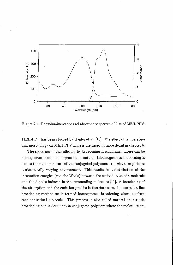
Typical absorption spectra of conjugated polymers are however signifi
cantly broader with less vibronic structure. Figure 2.4 shows the photolumi-
nescence and absorption spectra measured for a film of MEH-PPV at room
temperature. This is partly due to the fact that polymers have a random
distribution of conjugation lengths, which all contribute to the spectrum
- the absorption spectra sample all conjugated segments. Each individual
chain gives rise to an electronic structure, with a corresponding absorption
spectrum. I t has been suggested that the absorption spectrum of a polymer
can be thought of as the superposition of the contributions from each of the
diflferent conjugation lengths [7 .
The disorder in the sample is also an important factor which alfects the

CHAP"^^^ 9 TUT?nT}V nVP r^nATUTriATT?!^ A/TATT^GTAT Q 0 0
Eximction Fluorescence cocmcicnl
S , ^ S, .absorption S, S, emission
Figure 2.3: Jablonski configuration coordinate diagram from Kearwell and
Wilkinson [6 .
shape of the spectrum. In an ordered sample the vibronic lines become
sharper, this therefore reveals the underlying vibronic structure which is not
observed in a disordered sample. As conjugated polymers are cooled down,
this increase in the vibronic structure is seen in the spectra. This is because
conjugated polymers at room temperature have twists around the phenylene
rings which break the conjugation and shorten the effective chain length. As
the sample is cooled, the chains become more planar, and therefore more
ordered, which leads to an observed increase in the vibronic features. The
temperature dependence of conjugated polymers has been studied by Pichler
and Yu [8, 9]. A red shift of the spectrum is also seen, as the emission from
longer chain lengths is at lower energy. The effect of film morphology in
S 300 <
S 200
300 400 500 600 Wavelength (nm)
700 800
Figure 2.4: Photoluminescence and absorbance spectra of film of MEH-PPV.
MEH-PPV has been studied by Hagler et al. [10]. The effect of temperature
and morphology on MEH-PPV films is discussed in more detail in chapter 6.
The spectrum is also affected by broadening mechanisms. These can be
homogeneous and inhomogeneous in nature. Inhomogeneous broadening is
due to the random nature of the conjugated polymers - the chains experience
a statistically varying environment. This results in a distribution of the
interaction energies (van der Waals) between the excited state of a molecule
and the dipoles induced in the surrounding molecules [11]. A broadening of
the absorption and the emission profiles is therefore seen. In contrast a line
broadening mechanism is termed homogeneous broadening when it afi'ects
each individual molecule. This process is also called natural or intrinsic
broadening and is dominant in conjugated polymers where the molecules are

CHAPTER 2. THEORY OF CONJUGATED MATERIALS 24
rigidly fixed. Homogeneous broadening is related to the lifetime of a system and can be described with a Lorentzian line-shape [12 .
2.4 Excitons
An exciton is a bound electron-hole pair which forms either through direct
optical excitation or through electrical excitation. One of the most convenient
ways to generate excitons is through optical excitation. Absorption and
photoluminescence spectroscopy are therefore useful ways of studying the
nature of the photoexcitations in these materials. An exciton can be thought
of as a bound electron hole pair. There are two main types of exciton - Frenkel
excitons where the electron-hole pair is located on one molecular unit and
Mott-Wannier excitons where it extends over many molecular units. I t is
also possible to have the intermediate state, where an exciton extends over
only a few molecular units, this is called a charge transfer exciton. A typical
radius for Wannier excitons is between 4 and 10 nm.
Excitons are formed under optical or electrical excitation. Time-resolved
luminescence work has shown that after excitons are created they migrate
from the shorter (higher energy) chain segments to longer (lower energy)
chain segments on a picosecond timescale [13-15]. This effect is well known
in molecular organic systems and it is used to explain the blue shift observed
from emission measured on short timescales after photoexcitation compared
to steady state emission spectra.
Excitons may exist as triplets or as singlets depending on their spin config
uration. Singlet excitons can be formed through optical excitation or through
injection of electrons and holes of a device. Triplet excitons can only be di
rectly formed by electrical excitation however they are also formed through
intersystem crossing from the singlet exciton, which is discussed in section
2.5. The singlet state has an antisymmetric spin wavefunction, whereas the

CHAPTER 2. THEORY OF CONJUGATED MATERIALS 25
triplet has a symmetric wavefunction. The possible combinations of spins are shown below. There are three possible superpositions which give rise to triplets but only one which gives rise to the singlet state. The arrows represent the spin state of the electrons in the wavefunction.
singlet = '^[in)-in)] (2.1)
triplet = [ ( t ; ) + in)] (2.2)
triplet = ( t t ) (2.3)
triplet = (ii) (2.4)
2.5 Quenching Mechanisms
The photoluminescence quantum yield of conjugated polymers (PLQY) can
be as high as 50 % [16]. However, the fact that the PLQY is not 100 %
implies that non-radiative decay channels compete with the radiative decay.
The photoluminescence quantum yield is related to the radiative and
non-radiative rate constants by:
kR + Knr
where ^ j , ; is the PLQY, k / j is the radiative decay rate and k^vR is the
non-radiative decay rate.
Therefore the rate of non-radiative decay is of great importance, as a fast
non-radiative decay will have an adverse affect on the quantum yield of the
polymer.

CHAPTER 2. THEORY OF C0iVJJ7GATED MATERIALS 26
Possible non-radiative decay mechanisms are multiple phonon emission, and charge separation (through intermolecular energy transfer) which are discussed in more detail elsewhere [17]. Another non-radiative decay mechanism is the migration of excitons to quenching sites formed for instance by aggregates of excimers.
The formation of triplet states through intersystem crossing can lead to
luminescence, however, as this is very weak, any intersystem crossing may
reduce the overall luminescence efficiency of the polymer. The diagram in
figure 2.5 shows how excitons photoexcited through optical pumping can
form triplet excitons. Triplet excitons are long lived excited states for which
the decay to the ground state is a forbidden transition. The triplet exciton
therefore decays on time-scales from milliseconds to seconds. The emission
from triplets (phosphorescence) is extremely weak, however i t has recently
been observed in polymer systems [18]. As the direct formation of triplets
is spin forbidden, they are only formed by intersystem crossing from singlet
excitons. The long lifetime of the triplet can however lead to quenching of
the excitation.
The triplet energies have recently been measured for a variety of polymers
using pulse radiolysis by Monkman et al [19 .
2.6 Intermolecular Interactions
Although conjugated polymers can often be considered to be one-dimensional,
interactions between the chains do exist, and just as in organic dye systems,
the optical properties can be vastly modified when this interaction is present.
In the case of conjugated polymers, there are two important intermolecular
interactions. Aggregates, also called physical dimers (in the case of two
molecules) are a ground state species, and excimers which are excited state
dimers [11]. There is evidence for such intermolecular interactions (although

CHAPTER 2. THEORY OF CONJUGATED MATERIALS 27
Triplet
Singlet
Si
Absorption
Inter-system Crossing
T
T
Phosphorescence
Figure 2.5: Electronic transitions showing singlet and triplet states
it is not clear whether they are aggregates or excimers) in polymers such as
CN-PPV [20 .
Aggregates result from the overlap between the wavefunctions of two iden
tical closely spaced molecules. These molecules dimerise, causing a splitting
of the exciton into a lower and an upper energy level. The orientation of
the transition dipoles determines the optical transitions, i.e. if the dipoles
are parallel, transition to one of the levels is forbidden, i f they are not par
allel then both transitions are allowed. In general, aggregates have a broad
emission spectrum which is shifted to the red of the absorption spectrum.
Aggregates are also characterised by a long emission lifetime and a broad

CHAPTER 2. THEORY OF CONJUGATED MATERIALS 28
absorption spectrum in comparison to the solution absorption. In contrast to aggregates, the absorption spectrum in molecules that form
excimers is that which is expected for the monomer, but they also show a
broad structureless emission spectrum. These excimers form between an
excited molecule and a molecule in the ground state. The repulsive force
between the ground and excited state molecules causes the broad emission
spectrum. There has been a great deal of interest in intermolecular interac
tions and how they affect the optical properties of polymers [20-23]. It has
been proposed that inter-chain excitations are less mobile than intra-chain
excitations possibly because inter-chain excitations are more localised on the
region where the dimer is formed [11 .
The effect of intermolecular interaction on the gain is extremely important
in the context of this thesis and on the future of conjugated polymer elec
trically pumped lasers. Work by Kozlov and Tessler [24, 25] has shown that
in both small organics and conjugated polymers polaron pairs are formed
which, under electrical excition can introduce an absorption in the same
spectral region as the gain. This could quench the gain and therefore hinder
laser action. However, recently lasing was observed in a single crystal of
tetracene [26 .

BIBLIOGRAPHY 29
Bibliography
1] J. McMurry. Organic Chemistry. Brooks/Cole Publishing, 1984.
2] P. Sykes. A Guidebook to Mechanism in Organic Chemistry. Longman,
1961.
3] W.P. Su and J.R. Schrieffer. Proc. Natl. Acad. Sci, 77:5626, 1980.
4] W.P. Su, J.R. Schrieff'er, and A.J. Heeger. Physical Review Letters,
42:1698, 1979.
5] N.C. Greenham. Electroluminescence in Conjugated Polymers. PhD
thesis, 1995.
6] A. Kearwell and F. Wilkinson. Transfer and Storage of Energy by
Molecules. Wiley, New York, 1969.
7] B.E. Kohler and I.D.W. Samuel. Chemical Physics Letters, 213:472,
1993.
8] K. Pichler, D. A. Halliday, D. D. C. Bradley, P. L. Burn, R. H. Friend,
and A. B. Holmes. Journal Of Physics-Condensed Matter, 5(38):7155-
7172, 1993.
9] J. W. Yu, M. Hayashi, S. H. Lin, K. K. Liang, J. H. Hsu, W. S. Fann,
C. I . Chao, K. R. Chuang, and S. A. Chen. Synthetic Metals, 82(2):159-
166, 1996.
10] T. W. Hagler, K. Pakbaz, K. F. Voss, and A. J. Heeger. Physical Review
B-Condensed Matter, 44(16):8652-8666, 1991.
[11] I .D.W. Samuel. Primary Photoexcitations in Conjugated Polymers:
Molecular Exciton versus Semiconductor Band Model. World Scientific,
1998. Chapter 7.
BIBLIOGRAPHY 30
12] 0. Svelto. Principles of Lasers. Plenum Press, 1982.
13] G. R. Hayes, I . D. W. Samuel, and R. T. PhilUps. Physical Review
B-Condensed Matter, 52(16):11569-11572, 1995.
14] I . D. W. Samuel, B. Crystall, G. Rumbles, P. L. Burn, A. B. Holmes,
and R. H. Friend. Synthetic Metals, 54(1-3):281-288, 1993.
15] B. Mollay, U. Lemmer, R. Kersting, R.F. Mahrt, H. Kurz, H.F. Kuffman,
and H. Bassler. Physical Review B, 50:10769, 1994.
16] N. C. Greenham, I . D. W. Samuel, G. R. Hayes, R. T. Phillips, Yarr
Kessener, S. C. Moratti, Holmesm A.B., and R.H. Friend. Chemical
Physics Letters, 241(l-2):89-96, 1995.
17] R.H. Friend, D.D.C. Bradley, and P.D. Townsend. Journal of Physics
D, 20:1367, 1987.
18] Y.V. Romanovskii, A. Gerhard, B. Schweitzer, U. Scherf, R.I. Personov,
and H. Bassler. Physical Reveiw Letters, 84:1027, 2000.
19] A. P. Monkman, H. D. Burrows, M. D. Miguel, I . Hamblett, and
S. Navaratnam. Chemical Physics Letters, 307(5-6):303-309, 1999.
20] I . D. W. Samuel, G. Rumbles, C. J. Collison, S. C. Moratti, and A. B.
Holmes. Chemical Physics, 227(l-2):75-82, 1998.
21] 1. D. W. Samuel, G. Rumbles, and C. J. Collison. Physical Review
B-Condensed Matter, 52(16):11573-11576, 1995.
22] M. Yan, L. J. Rothberg, E. W. Kwock, and T. M. Miller. Physical
Review Letters, 75(10):1992-1995, 1995.
23] M. Yan, L. J. Rothberg, F. Papadimitrakopoulos, M. E. Galvin, and
T. M. Miller. Physical Review Letters, 72(7):1104-1107, 1994.

BIBLIOGRAPHY 31
24] V. G. Kozlov, P. E. Burrows, G. Parthasarathy, and S. R. Forrest. Applied Physics Letters, 74(8):1057-1059, 1999.
25] N. Tessler, N.T. Harrison, and R.H. Friend. Advanced Materials, 10:64, 1998.
26] J.H. Schon, Ch. Kloc, A. Dodabalapur, and B. Batlogg. Science, 289:599, 2000.

Chapter 3
Theory of Stimulated Emission in Conjugated Materials
3.1 Introduction
Organic lasers were first reported in the 1960's using both organic molecules 1] and later dye doped polymers [2, 3]. However it was not until 1992 that
evidence emerged that it would be possible to observe stimulated emission in conjugated polymers [4, 5 .
In this chapter the basic principles of stimulated emission and laser operation are discussed. Conjugated polymers can be thought of as 4-level laser systems similar to dye laser systems. Since the observation of spectral line narrowing (SLN) in conjugated polymers, (the dramatic narrowing of the emission spectrum at higher excitation densities) there has been much discussion in the literature concerning the mechanism for this phenomenon. The main types of mechanism (amplified spontaneous emission (ASE), super-fluorescence (SF) and superradiance (SR)) will be outlined. The thin films used in this work are asymmetric waveguides therefore in the last part of this chapter the general properties of waveguides and the theory behind the
32

CHAPTER 3. STIMULATED EMISSION 33
cut-ofF thickness for TE and TM modes are discussed.
3.2 Spontaneous and Stimulated Emission
B lni,iiii un-lm
(u,n)
un,lm
(l,m)
Figure 3.1: Illustration of Einstein Coefficients from Pope and Swenberg [6 .
The process of absorption and photoemission in conjugated materials was described in chapter 2. Einstein developed a formalism for the rate of transitions between two energy levels. The diagram in figure 3.1 [6] represents two electronic levels where the subscripts Im represent the mth vibrational level of the Ith electronic state and un represent the nth vibrational level of the uth electronic state. The absorption of Ught is represented by Bim,un- Fol-

CHAPTERS. STIMULATED EMISSION 34
lowing the initial photoexcitation there are two emissive processes possible, the first is the process of spontaneous emission, where the rate is given by A u n , ! m - This is a random process that determines the normal radiative decay of the excited state.
Spontaneous emission occurs when an atom, excited to a higher energy state by the absorption of a photon, undergoes a relaxation back to the ground state in which a photon of energy hu = E2 - Ei is emitted. The average number of atoms undergoing this spontaneous transition from state 2 with a population N2 to state 1 per unit time is:
dt ^ itspont)2l ^ ^
where A21 is the spontaneous transition rate and t(spont)2i is the spontaneous emission lifetime associated with the transition 2-^1
The second radiative decay mechanism is stimulated emission, for which the rate constant is given by Bun,im- For stimulated emission to occur, a photon with an energy equal to the energy gap of the two states must interact with an electron in the excited level un. Stimulated emission can occur at nearly the same rate as the absorption process and it was shown by Einstein that:
Bun,lm — -S/m.uTi (3-2)
and
(3.3)
where u is the frequency of the transition, no the index of refraction of the medium and c the speed of light.

CHAPTERS. STIMULATED EMISSION 35
3.3 Laser Operation The work in this thesis is not concerned with making a conjugated polymer laser, rather with studying the gain in the polymers, and ways in which the gain can be controlled. Although there is still some controversy over the mechanism for the spectral line narrowing seen from these materials in thin film waveguides, it is thought not to be due to laser action, as there is not sufficient feedback from the edges of the film. Experiments have shown that roughening the edges of the film does not aff"ect the emission properties [7 . However, some of the phenomena associated with lasers, such as a population inversion, threshold for stimulated emission and gain saturation, are relevant to the structures used in this work.
The word LASER is an acronym which stands for 'light amplification by stimulated emission of radiation'; however a laser is more than a device for amplifying light. In general a laser consists of an optical amplifier and a feedback mechanism of some sort. A cavity can be formed by the partially reflecting mirrors as in a ruby laser, the sides of a crystal, as in a semiconductor laser or by a grating arrangement. Common ways to introduce feedback in organic semiconductor lasers are distributed Bragg reflectors (DBR) [8-10], distributed feedback (DFB) waveguides [11] and whispering gallery mode structures [12]. One of the main features of a laser is that it emits coherent light. Coherent emission occurs when a photon interacts with the excited molecule causing another photon to be emitted. This photon will have the same phase and direction as the other photons present.
By considering the populations Ni in level 1 and N2 in level 2 of a system, it can be shown that the rate of change of emission intensity per unit length is given by [13]:
^ = {N,- N,)Cg{v)h (3.4)

CHAPTERS. STIMULATED EMISSION 36
where C is a constant which depends on the speed of hght, the refractive index, the frequency of the emission and the spontaneous decay time; is the emission intensity and g(i/) is the photoluminescence spectral line-shape.
This has the solution :
i,{z) = uoy^"^' (3.5) where 7(2/) is the exponential gain constant and is given by:
= (A 2 - N^)Cg{u) (3.6)
A population inversion is defined as when the excited state is more highly populated than a state of lower energy, i.e. when N2 > Ni. Equation 3.5 shows that the intensity grows exponentially if the population is inverted, or attenuated if the population is not inverted (N2 < Ni). In the ceise where the population is inverted, amplification of the incident wave occurs. This is required for laser operation and is described through the exponential gain coefficient 7(1 ). A typical value for the gain coefficient, for instance in a ruby laser where the difference in the populations between level 1 and level 2 is 5 X 10 ' cm~^, is 5 X 10~ cm~^. This implies that a wave passing through the ruby rod of 1 cm will be amplified by approximately 5% [14 .
The equation above implies that light intensity will increase without bound if a population inversion exists. However, in practice, gain saturation limits the amplification which is possible. When a light wave is very strongly amplified a substantial fraction of the excitations are depleted. Any further increase in the pump intensity does not increase the amphfication. There is in fact a decrease in the gain coefficient when gain saturation takes place [13 .
A defining feature of laser operation is a threshold pump intensity, below which only spontaneous emission is observed and above which stimulated

CHAPTER 3. STIMULATED EMISSION 37
emission is produced. In a laser the threshold is reached when the round trip gain exceeds the round trip losses in the cavity.
3.4 4-level Lasers
Laser dyes are essentially large conjugated molecules which are known to behave as 4-level systems [14]. The stimulated emission observed in conjugated polymers has therefore been assigned to 4-level laser systems [7, 15]. This section describes the underlying principles of a 4-level laser system.
4 \
Pump transition
Very fast transition rate =0332
aser
Ground State E i » k T
Figure 3.2: A 4-level laser system.
The diagram in flgure 3.2 shows the energy levels present in a 4-level laser system. A pump source is used to excite the dye molecule, which.

CHAPTER 3. STIMULATED EMISSION 38
by absorbing the pump light undergoes a transition into a higher excited state. Most of the dye molecules will then relax quickly to the state E2. This happens on a very fast time-scale, on the order of 10" ^ s and is a radiationless transition. The lifetime of the state E2 is much longer - this allows the population to build up until the population in E2 is greater than the population in Ei. Stimulated emission then occurs from E2 to Ei with the emission of a photon. Finally there is another fast, radiationless transition back to the ground state. In a conjugated polymer system the lower two levels correspond to the So ground state and the upper two levels correspond to the Si flrst excited state. The fast radiationless transitions are vibronic transitions to the lowest level in each state. The diagram in figure 3.3 below shows how the conjugated polymer energy level diagram corresponds to a 4-level laser system.
S i
Absorption
•0
Y\ Stimulated Emission
Figure 3.3: 4-level laser system

CHAPTERS. STIMULATED EMISSION 39
3.5 Mechanisms for Spectral Line-narrowing 3.5.1 A S E
Spectral line-narrowing is the dramatic narrowing of the broad emission spectrum seen when organic materials are photoexcited with high excitation densities. The widely accepted explanation for the observation of the narrowing of the emission spectrum in conjugated polymers is amplified spontaneous emission (ASE) [16-19]. This phenomenon has been studied extensively in dye lasers [14], however it is normally thought of only as being in competition with the lasing mode, and much eff'ort goes into reducing the ASE. In ASE, photons which are spontaneously emitted in a photoexcited region cause a radiative de-activation of other emitters as they propagate through the medium. The overall gain experienced by an emitted photon propagating through the excited region is given by G:
G = e ^ ' (3.7)
where g is the gain coefficient and / is the path length inside the sample. The ASE intensity therefore depends on the length of the pump stripe used to excite the polymer film. The importance of waveguiding is also obvious from this equation - the further the photon travels, the more it can be amplified. As equation 3.7 shows, the gain coefficient is a function of the frequency (and hence the wavelength) of the light. As the pump intensity increases, the wavelengths at the peak of the gain will experience a greater amplification, at the expense of the hght at other wavelengths. This leads to a dramatic narrowing of the emission spectrum and very intense emission. The peak of the ASE is therefore determined by the peak of the net gain, where the net gain depends on the material gain and ground state and excited state
CHAPTER 3. STIMULATED EMISSION 40
absorption. The line-width of the ASE in conjugated polymers is generally 6-10 nm.
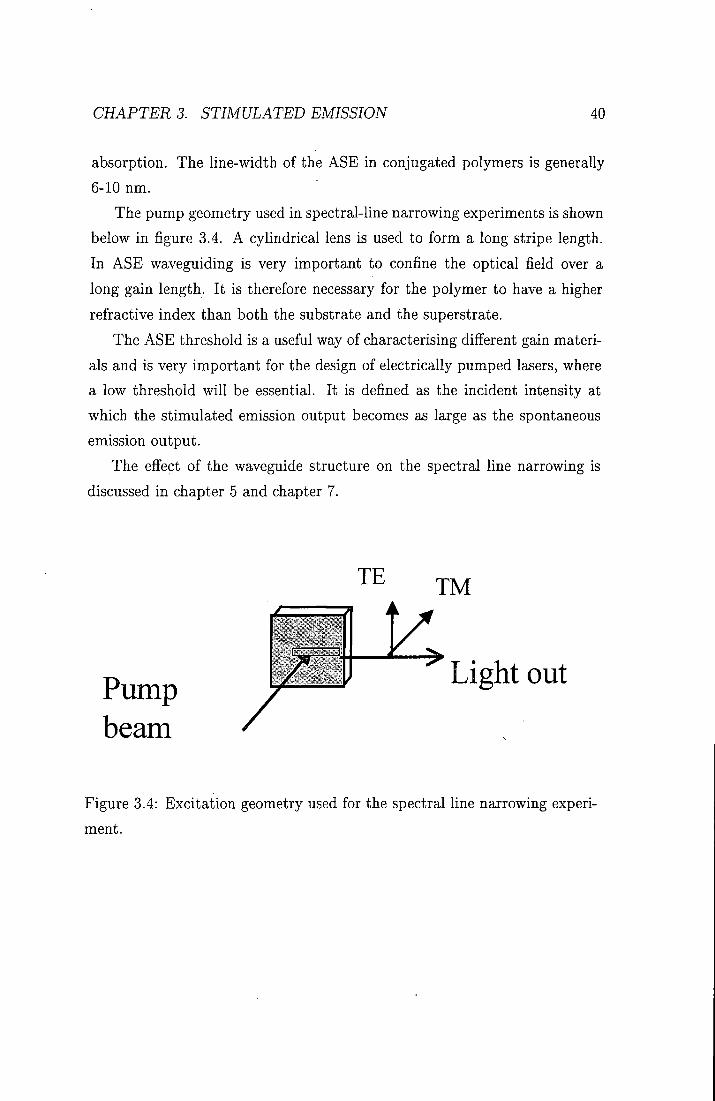
The pump geometry used in spectral-line narrowing experiments is shown below in flgure 3.4. A cylindrical lens is used to form a long stripe length. In ASE waveguiding is very important to conflne the optical field over a long gain length. It is therefore necessary for the polymer to have a higher refractive index than both the substrate and the superstrate.
The ASE threshold is a useful way of characterising different gain materials and is very important for the design of electrically pumped lasers, where a low threshold will be essential. It is defined as the incident intensity at which the stimulated emission output becomes as large as the spontaneous emission output.
The effect of the waveguide structure on the spectral line narrowing is discussed in chapter 5 and chapter 7.
TE TM
Pump beam
Light out
Figure 3.4: Excitation geometry used for the spectral line narrowing experiment.

CHAPTERS. STIMULATED EMISSION 41
3.5.2 Co-operative Emission Processes
There are two types of cooperative emission process - superfluorescence (SF) and superradiance (SR), both of which have been assigned to the spectral line-narrowing in conjugated polymers [20-23]. In co-operative emission processes a 'super dipole', which gives rise to extremely rapid coherent emission and narrowed spectra [24] is formed.
SF takes place after an induction time when individual dipoles couple together. There is a time delay in the emission before a rapid decay, which is expected to be of the order of 10~ ^ s for a disordered material such as a conjugated polymer [23 .
SR typically arises from aggregates which are coupled to the ground state, however it is usually found in materials with narrow absorption bands and small Stokes shifts which makes it unlikely to be the mechanism for spectral line narrowing in conjugated polymers. Work by Frolov et al. states that the important characteristics of SR are the existence of a threshold intensity and a decrease in the spontaneous emission lifetime [22]. They argue that ASE cannot be responsible for the spectral line narrowing and they show from a simple calculation that the position of the gain should be blue shifted as the thickness of the film is decreased, which they do not see. There is however more recent evidence which shows that a blue shift of the gain spectrum is seen as the film thickness is decreased [25 .
3.6 Bimolecular Exciton Annihilation
Bimolecular exciton annihilation is a non-radiative process that occurs at high excitation densities and is therefore a competing process to stimulated emission. An understanding of the dynamics of bimolecular exciton annihilation is very important for the reahsation of laser devices, as devices must

CHAPTERS. STIMULATED EMISSION 42
operate well below the threshold for any competing non-radiative process. An additional factor of —^N"^ must be added to rate equations to take account of this process where 7 is the bimolecular annihilation coefficient [26 .
3.7 Analysis of Waveguide Modes
The films discussed in this thesis can be considered as thin film optical waveguides. A diagram of such a waveguide is shown below in figure 3.5. The polymer layer is sandwiched between the substrate (glass or quartz) and the superstrate (air). For light to propagate in the waveguide, the polymer films must have a higher refractive index than both the substrate and the superstrate.
In order to analyse the modes in the waveguide it is necessary to use the slab (planar) model, which assumes that there is no variation in one direction (in this case the y direction) and that the modes propagate in the z direction [13]. All fields in the waveguide will satisfy the standard Helmholz equation [27]:
V'E(r) + ( y ) ' n 2 ( r ) E ( r ) = 0 (3.8)
Where n is the index of refraction in each layer, A is the wavelength of light in free space and E(r) is the electric field as a function of distance r.
In order to solve this equation solutions of the form:
E(r,i) = E(a;,y)e'(' *-^^) (3.9)
are used with the boundary conditions that there is continuity of the tangential component of E and H at the air/polymer and polymer/glass interfaces.

CHAPTER 3. STIMULATED EMISSION 43
Air
Polymer
Substrate
X
Y
Figure 3.5: Schematic diagram of a waveguide.
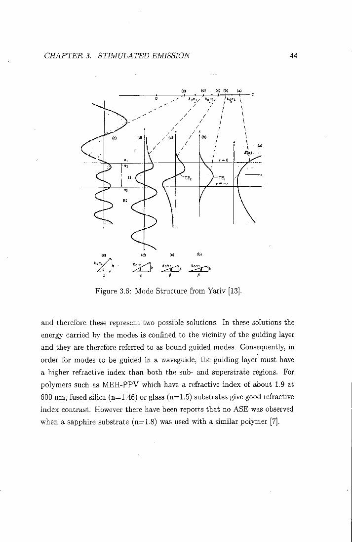
There are a number of different-solutions to this equation all shown in flgure
3.6. Figure 3.6a shows the results for the case where P > kon2. P is the
propagation constant and A;o is the free space propagation constant. Here the field increases without bound on either side of the waveguide. This solution is not physically realizable. Figure 3.6 b and c show solutions for the case where koUs < P < kon2. These graphs have exponential decays in both the substrate and superstrate and a sinusoidal solution in the polymer region
CHAPTER 3. STIMULATED EMISSION 44
(e) (d) (c) (b) (a)
' O " ! / * I 5 _ ' I 3 / Mo,"! 1
Figure 3.6: Mode Structure from Yariv [13 .
and therefore these represent two possible solutions. In these solutions the energy carried by the modes is confined to the vicinity of the guiding layer and they are therefore referred to as bound guided modes. Consequently, in order for modes to be guided in a waveguide, the guiding layer must have a higher refractive index than both the sub- and superstrate regions. For polymers such as MEH-PPV which have a refractive index of about 1.9 at 600 nm, fused silica (n=1.46) or glass (n^^l.S) substrates give good refractive index contrast. However there have been reports that no ASE was observed when a sapphire substrate (n=1.8) was used with a similar polymer [7 .

CHAPTERS. STIMULATED EMISSION 45
By solving the Helmholz equation for the guided mode in an asymmetric waveguide where the guiding layer has a thickness t, the following results are obtained [13]:
Ey = (7e-«^ (3.10)
Ey = C (cos{hx) - j^sin{hx)^ (3.11)
Ey = C (cos{hx) + ^sin{hx)) 6 ^+*' (3.12)
Equation 3.10 is valid for the substrate region, equation 3.11 is for the guiding layer and equation 3.12 is for the superstrate region. The variables h,p and q are given by:
h = Jnl[^f-P^ (3.13)
P = \jp'-n's ( f ) ' (3.14)
^ - / ^ ^ - n ^ ( f ) ' • (3.15)
ris is the refractive index of the substrate, rip is the refractive index of the polymer and Ua is the refractive index of the air.
This leads to the following equation:
There are two types of bound mode possible in a waveguide. The first is the
CHAPTER S. STIMULATED EMISSION 46
TE (transverse electric) mode which is polarized with the electric field in the y-direction. The field components are therefore Ey,H^,Hj; where E denotes the electric field and H denotes the magnetic field. The direction of propagation is the z-direction as shown in figure 3.5. Similarly the TM (transverse magnetic) mode has the magnetic field component in the y-direction and therefore has the field components E.y,E2,Ex.
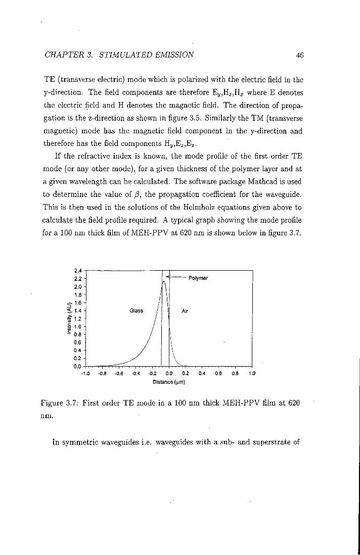
If the refractive index is known, the mode profile of the first order TE mode (or any other mode), for a given thickness of the polymer layer and at a given wavelength can be calculated. The software package Mathcad is used to determine the value of P, the propagation coefficient for the waveguide. This is then used in the solutions of the Helmholz equations given above to calculate the field profile required. A typical graph showing the mode profile for a 100 nm thick film of MEH-PPV at 620 nm is shown below in figure 3.7.
2.4 2.2 2.0 1.8 H
< 1.4
5 1.0 - 0.8 H
0.6 -0.4 -0 . 2 -0.0 -
-1
Polymer
Air
0 -0.8 -0.6 -0.4 -0.2 0.0 0.2 0.4 0.6 0.8 1.0
Distance {\im)
Figure 3.7: First order TE mode in a 100 nm thick MEH-PPV film at 620
nm.
In symmetric waveguides i.e. waveguides with a sub- and superstrate of

CHAPTERS. STIMULATED EMISSION 47
identical refractive indices, there is no cut-off thickness for the lowest order
TE and T M modes and so light of any wavelength will be guided in these
modes. However, for an asymmetric waveguide, a distinct cut-off thickness
exists for a given wavelength, below which light of this wavelength will not
be guided. At the cut-off thickness, the effective refractive index of the mode
(/5A/27r) is equal to the refractive index of the substrate (n.,). Therefore p,
in equation (3.14) is zero.
Rearranging equation 3.16 with p=0 yields the expression for the cut-off
of an asymmetric guide:
t = rtan-^ ( r ) (3.17) h \hj ^ ' Measurement of the cut-off thickness and the effect it has on the spectral-
line narrowing are investigated in more detail in chapter 7.
3.8 Summary
In this chapter the principles of laser operation have been described. A 4-level
laser system has been examined and discussed in relation to the energy levels
in conjugated polymers. The process of waveguiding has been examined in
detail and the possible mechanisms for spectral line-narrowing have been
described.

BIBLIOGRAPHY 48
Bibliography 1] D.J. Moranta, B.G. White, and A.J.C. Wright. Jounal of Chemical
Physics, 37:2041, 1962.
2] B.H. Soffer and B.B. McFarland. Applied Physics Letters, 10:266, 1967.
3] H. Kogelnik and C.V. Shank. Applied Physics Letters, 18:152, 1971.
4] D. Moses. Applied Physics Letters, 60(26):3215-3216, 1992.
5] N. Tessler. Advanced Materials, ll(5):363-370, 1999.
6] M. Pope and C.E. Swenberg. Electronic Processes in Organic Crystals
and Polymers. Oxford Science Publications, 2nd edition, 1999.
7] X. A. Long, A. Malinowski, D. D. C. Bradley, M. Inbasekaran, and E. P.
Woo. Chemical Physics Letters, 272(l-2):6-12, 1997.
8] N. Tessler, G. J. Denton, and R. H. Friend. Nature, 382(6593):695-697,
1996.
9] V. Bulovic, V. B. Khalfin, G. Gu, P. E. Burrows, D. Z. Garbuzov, and
S. R. Forrest. Physical Review B-Condensed Matter, 58(7):3730-3740,
1998.
10] A. Schulzgen, C. Spiegelberg, M. M. Morrell, S. B. Mendes, B. Kippelen,
N. Peyghambarian, M. F. Nabor, E. A. Mash, and P. M. AUemand.
Applied Physics Letters, 72(3):269-271, 1998.
11] C. Kallinger, M. Hilmer, A. Haugeneder, M. Perner, W. Spirkl, U. Lem-
mer, J. Feldmann, U. Scherf, K. Mullen, A. Gombert, and V. Wittwer.
Advanced Materials, 10(12):920, 1998.

BIBLIOGRAPHY 49
12] M. Berggren, A. Dodabalapur, Z. N. Bao, and R. E. Slusher. Advanced Materials, 9(12):968, 1997.
13] A. Yariv. Optical Electronics in Modern Communications. Saunders
College Publishing, 5th edition, 1997.
14] F.J. Duarte and L.W. Hillman. Dye Laser Principles. Academic Press,
1990.
15] A. Schulzgen, C. Spiegelberg, M. M. Morrell, S. B. Mendes, P. M.
AUemand, Y. Kawabe, M. KuwataGonokami, S. Honkanen, M. Fallahi,
B. Kippelen, and N. Peyghambarian. Optical Engineering, 37(4): 1149-
1156, 1998.
16] V. Doan, V. Tran, and B. J. Schwartz. Chemical Physics Letters, 288(2-
4):576-584, 1998.
17] F. Hide, M. A. DiazGarcia, B. J. Schwartz, M. R. Andersson, Q. B. Pei,
and A. J. Heeger. Science, 273(5283):1833-1836, 1996.
18] C. Zenz, W. Graupner, S. Tasch, G. Leising, K. Mullen, and U. Scherf.
Applied Physics Letters, 71(18):2566-2568, 1997.
19] M. D. McGehee, R. Gupta, S. Veenstra, E. K. Miller, M. A. DiazGarcia,
and A. J. Heeger. Physical Review B-Condensed Matter, 58(11):7035-
7039, 1998.
20] S. V. Frolov, Z. V. Vardeny, and K. Yoshino. Physical Review B-
Condensed Matter, 57(15) :9141-9147, 1998.
[21] S. V. Frolov, M. Ozaki, W. Gellermann, M. Shkunov, Z. V. Vardeny,
and K. Yoshino. Synthetic Metals, 84(1-3) :473-474, 1997.

BIBLIOGRAPHY 50
22] S. V. Frolov, W. Gellermann, Z. V. Vardeny, M. Ozaki, and K. Yoshino. Synthetic Metals, 84(1-3) :471-472, 1997.
23] S. V. Frolov, W. Gellermann, M. Ozaki, K. Yoshino, and Z. V. Vardeny.
Physical Review Letters, 78(4):729-732, 1997.
24] R. Bonifacio and L.A. Lugiato. Physical Review A, 11:1507, 1975.
25] A.K. Sheridan, G.A. Turnbull, A.N. Safanov, and I.D.W. Samuel.-P%5-
ical Review B, 62(18):R11929, 2000.
26] A. Haugeneder, M. Neges, C. Kallinger, W. Spirkl, U. Lemmer, and
J. Feldman. Jounal of Applied Physics, 85:1124, 1999.
27] D. Marcuse. Theory of Dielectric Optical Waveguides. Academic Press,
1974.
Chapter 4
Experimental Techniques
4.1 Introduction
In this chapter the main experimental techniques which were used to in
vestigate new materials, to assess their usefulness as amplification media,
and to characterise the gain observed, are discussed. The first section deals
with the preparation of high quality thin films for optical measurements.
The polymers used in this work were supplied as a powder from a variety
of sources. The MEH-PPV was supplied by Covion and was synthesised
via a Heck reaction. The novel PPV derivatives investigated in chapter 5
were made by Andreas Bacher and Andreas Bleyer at Sheffield University.
The two perylene dyes used in the energy transfer experiments in chapter
9 were supplied by BASF in Germany and were used in the host matrix
poly-methylmethacralate (PMMA). The methods of optical charaterisation;
absorption and photoluminescence, will be described. The technique of mea
suring the photoluminescence quantum yield is then discussed in detail. In
the final section, the experimental set-up used to investigate gain in thin
film waveguides is described. The observation of a sharp decrease in the
line-width of the emission spectrum at high excitation densities (spectral-
51

CHAPTER 4. EXPERIMENTAL TECHNIQUES 52
line-narrowing) is a characteristic feature of gain in conjugated materials. This technique is a useful way of probing the excited state dynamics.
4.2 Film Preparation
The main techniques used for producing good quality thin films of conjugated
polymers or small organics in a host matrix are spin coating or drop casting.
Drop casting produces thick films, however the optical quality is not as good
as the films produced by spin coating and the thickness of the films, is not
uniform, especially at the centre and the edge of the substrate. Al l the
films used in this work were produced by spin casting as high optical quality
was required. This was especially important in the SLN experiments where
imperfections in the film could affect the waveguiding necessary to produce
ASE.
Two different substrates were used in the experiments; the quartz sub
strates were circular with a diameter of 12 mm and were always used in
absorption measurements as quartz is transparent up to 6 eV. The glass
substrates were made from microscope slides cut using a diamond scribe to
squares 12 m m x l 2 mm. These were then cleaned in acetone and isopropanol
and dried using a nitrogen line.
Choosing the right substrate for the experiment is very important. For
some SLN experiments quartz was used as it has a lower refractive index
(1.46) than glass (1.51). In the SLN experiments it is vital to form a sub
strate/polymer/air waveguide in which the polymer has a refractive index
larger than the substrate. While polymers have a relatively high refractive
index, the perylene dyes, doped into PMMA have a refractive index lower
than 1.51. I t was therefore necessary to use quartz substrates for these ex
periments. However for the experiments with MEH-PPV, glass substrates
were used. I t was found that films on glass were of better optical quality,

CHAPTER 4. EXPERIMENTAL TECHNIQUES 53
in particular no edge bead formed at the edges of the film as with quartz substrates.
In order to prepare films of conjugated polymers, solutions with a con
centration of about 5 mg/ml were made. A suitable solvent was used for
example, toluene, tetrahodrofuran (THE) or chlorobenzene (CB). Once the
polymer was dissolved the solution was pipetted onto a substrate and spun
at between 1000 and 2500 rpm. The substrate was held on the chuck by
a vacuum. Films of between 50 and 300 nm could easily be formed. The
perylene dyes used in this work were doped into a host polymer matrix of
PMMA. PMMA with a molecular weight of 120 000 was used as supplied by
Aldrich. A typical solution of 200 mg of PMMA doped with 4 mg of dye in
1 ml of toluene would form films of around 3 /^m. The solutions were left to
stir overnight.
4.2.1 ]V[easurement of Film Thickness
The thickness of the films was measured using an alpha step surface pro-
filometer. A small section of the polymer film was removed using a scalpel
blade. The stylus of the profilometer was drawn across the film, tracing the
height at each point. An average could then be obtained between the level of
the top of the film and the level of the substrate, thereby giving a measure of
the film thickness. I t is also possible to get an estimate of the film thickness
i f an accurate measurement of the absorption coefficient is made. This is
discussed below.

CHAPTER 4. EXPERIMENTAL TECHNIQUES 54
4.3 Optical Characterisation 4.3.1 Absorption
Absorption and photoluminescence measurements are important techniques
for the characterisation of polymers. Together with time-resolved lumines
cence measurements, information about the type of ground and excited state
species and the inter- and intra-chain interactions can be gained [1-4]. The
absorption spectra were measured using a dual beam lambda 19 absorp
tion spectrometer. A reference sample of quartz or glass was placed in one
arm of the spectrometer and the sample in the other. Absorbances up to
about 2.5 could be measured accurately. A tungsten lamp was used for the
long wavelength light to 319 nm and a deuterium lamp was used for shorter
wavelengths. The light passed through a monochromator before hitting the
sample and was then detected using a photo-multiplier tube (PMT) detector.
In order to measure the absorption coefficient accurately for MEH-PPV 4
films with different thicknesses were made. These were placed in pairs in the
two arms of the absorption spectrometer. This technique avoids the problem
of reflection from the polymer air interface which causes an overestimate of
the absorption. The thickness of the films was measured using the surface
profilometer. The relation AA^cvAL where A A is the change in absorbance,
a is the absorption coefficient, and A L is the change in thickness for a pair
of samples, was used to calculate the absorption coefficient. The graph in
figure 4.1 below shows a plot of A A at the peak (550 nm) against AL. The
gradient of this graph and therefore the absorption coefficient for MEH-PPV
at 550 nm is 1.1 x 10^ cm~^ This can be used to estimate the thickness of
an MEH-PPV film if the peak absorbance is known.

CHAPTER 4. EXPERIMENTAL TECHNIQUES 55
50 100 150
Thickness (nm)
200 250
Figure 4.1: Absorbance differences at 550 nm against thickness differences
for pairs of films of MEH-PPV.
4.3.2 Photoluminescence
Photoluminescence spectra were measured using the fibre coupled CCD (charge
coupled device) spectrograph from Instruments SA. The samples were excited
using an Argon Ion laser at a suitable wavelength. The CCD spectrograph
consists of a flexible quartz fibre which carries the light into the heart of the
CCD. The light passes from the fibre through the entrance slit which deter
mines the resolution of the spectra and then hits a diff"raction grating which
spatially splits the light into its constituent wavelengths. This light then falls
onto the front of the CCD and electron-hole pairs are generated. The number

CHAPTER 4. EXPERIMENTAL TECHNIQUES 56
of electrons generated is proportional to the fight intensity. The integration time and the slit width can be used to control the amount of fight which is incident on the CCD. A calibration curve supplied by the manufacturer was used to calibrate the intensity of the spectra.
For some photoluminescence measurements, the Instruments SA fluoro-
max flourimeter was used. This consists of a xenon lamp which is monochro-
mated before it hits the sample, followed by another monochromator and
finally a Hamamatsu 928 PMT detector. This instrument has the advantage
that photoluminescence excitation (PLE) spectra could also be measured.
PLE spectra are produced when the excitation wavelength is scanned and
the emission is detected at one chosen wavelength. PLE spectra can give
useful information about the type of species formed under excitation, for
instance the presence of aggregates can be detected [5 .
4.4 Photoluminescence Quantum Yield
The photoluminescence quantum yield (PLQY) is defined as the number of
photons emitted by the sample divided by the number of photons absorbed.
In conjugated polymers luminescence is the result of radiative decay of singlet
excitons. However, this process competes with other non-radiative decay
processes and i t is the ratio of the rates of radiative (kr) and non-radiative
{knr) processes which determines the efficiency of the luminescence. In terms
of these rate constants the photoluminescence quantum yield is given by:
where (ppi is the PLQY, r is the overall lifetime which can be measured using
the time-correlated single photon counting technique and is the natural

CHAPTER 4. EXPERIMENTAL TECHNIQUES 57
Photodiode or CCD fibre
CCD Fibre
Excitation Source Entrance Port
Figure 4.2: The integrating sphere.
radiative lifetime. I f these quantities are measured, the rate constants can
be deduced. The measurement of the PLQY is described below.
4.5 Measurement of PLQY
4.5.1 Theory
In this section two methods for measuring the PLQY of thin films are de
scribed in detail. The measurement of an absolute quantum yield for films is
not a straightforward process. In contrast to solutions, which can be treated
as sources which emit light equally in all directions, films are anisotropic
emitters. The standard technique used for solutions, in which the emission
intensity is compared to a standard solution with a known PLQY, cannot
be used for films. Films do not emit light isotropically, partly because the

CHAPTER 4. EXPERIMENTAL TECHNIQUES 58
dipoles tend to align along the plane of the film. There is also the problem, that there is no suitable standard film with a known quantum yield. Waveguiding of light down the polymer film and refraction of light also play a role. For this reason the PLQY of films is measured in an integrating sphere which collects all the light emitted in every direction. The technique for measuring the PLQY of films in an integrating sphere was developed by Greenham et al. [6]. An integrating sphere is a hollow sphere coated white inside with a highly refiective and diffusive coating so that light is reflected equally in all directions. The flux of light which reaches the detector is therefore always directly proportional to the flux of light emitted from the sample. This technique also has the advantage that i t gives an absolute measure of the PLQY without the need for comparison with standards as in the typical method for measuring the quantum yield of solutions.
Experimental measurements of the PLQY were performed using a Ben-
tham IS4 integrating sphere shown in figure 8.12. The sphere has an entrance
slit approximately 2 mm in diameter for the excitation light which is either a
laser or the monochromated light from a xenon lamp. The samples were held
in the centre of the sphere with the front face perpendicular to the incoming
beam. Above the sample, before the collection port is a bafl3e which is there
to prevent light from being scattered directly into the collection apparatus.
The samples used had optical densities near 1 at the excitation wavelength.
The excitation power was controlled using metal neutral density filters. The
light emitted from the sample was collected in a port above the sample. In
the method developed by Greenham et al. a caHbrated photodiode was used
to collect the light. In order to stop the excitation light from being detected
at the same time as the emission from the sample, a cut-off filter was placed
in front of the photodiode. Kodak Wratten Gelatin filters were used as there
have been reports that other filters can fluoresce and therefore add to the
measured luminescence intensity [6 .

CHAPTER 4. EXPERIMENTAL TECHNIQUES 59
4.5.2 Photodiode Method
In order to measure the PLQY a measurement of the incident laser intensity
without the sample (Xiaser), and a measurement of the photoluminescence
intensity with the sample in the sphere is required (Xsampie)- However not
all the laser light is absorbed by the film, therefore the absorption at the
excitation wavelength is also required. This is given by 1-R-T where R and
T are the refiectance and the transmission of the sample respectively. These
were measured for each sample by using a photodiode and a laser beam.
Greenham et al. [6] derived the following equation for the quantum yield X,
in terms of measurable parameters:
^ _ Xsampie — {R + T ) Xsphere r,^
Xiaser {1 - R - T )
The term {Xsphere) is required to account for the fight which passes
through the sample but is then re-absorbed, leading to an increase in the
luminescence. This is measured by tilting the sample out of the path of the
laser beam so that direct excitation is avoided.
In order to achieve a correct PLQY value, further corrections have to be
applied to account for the response of the photodiode, the transmission of
the sphere and the effect of the cut-off filters. This correction Y, is given by:
^ ^ J SspneremG{X)F{X)dX ^^^^^
Ssphere{Xex)G{\ex) ! L{\)d\
where Ssphere is the transmission of the sphere, G is the quantum efficiency
of the calibrated photodiode, F is the transmission of the filter and L is the
emission spectrum of the sample and X^x is the excitation wavelength. The
PLQY is then given by:
- 0 = f (4.4)

CHAPTER 4. EXPERIMENTAL TECHNIQUES 60
This technique has been used to measure the PLQY of many conjugated polymer thin films [7]. Many polymers are very sensitive to exposure to air and light and the photoluminescence quantum yield will decrease rapidly if the samples are not stored in vacuum or nitrogen and in the dark. This process is believed to be due to photo-oxidation. In order to overcome the problems of photo-oxidation [8], freshly made samples were used in the experiments and the integrating sphere was flushed with nitrogen to remove most of the oxygen. The temporal decay of the PLQY of some polymers in air, nitrogen and in vacuum have been measured using a computer controlled time dependent measurement [9 .
4.5.3 CCD method
An alternative method was developed by de Mello in 1997 [10], in which a
CCD spectrograph is used as the detector instead of a calibrated photodiode.
In this technique, two spectra are recorded. The first spectrum is of the laser
beam, attenuated so that the CCD is not saturated. The second spectrum
is measured with the sample in the integrating sphere. Therefore both the
photoluminescence spectrum and a laser signal are recorded.
This has the benefit that both the laser and the photoluminescence spec
tra are measured simultaneously and there is therefore no need for a cut-off
filter. There is also no need to measure the reflection and transmission sep
arately as the absorption of the sample is simply given by the reduction in
integrated intensity of the laser signal. The PLQY is therefore given by:
0 P L = p ^ ^ " ^ ^ (4.5)
where Psampie is the integrated intensity of the photoluminescence spectrum,
Piaseri IS the intensity of the laser beam without a sample present and Piaser2

CHAPTER 4. EXPERIMENTAL TECHNIQUES 61
is the intensity of the laser beam with a sample present.
This method was successfully used for a range of samples and good agree
ment with the photodiode method was achieved. The CCD method has the
advantage that no cut-off filter is required and that the absorption is mea
sured directly without the need to measure the reflection and transmission
separately. However, i t has the disadvantage that the calibration of the CCD
is more likely to change with time.
Using this method the PLQY of the samples used in this work are sum
marised in table 4.1.
Luminescent Material Chapter PLQY
MEH-PPV 4,7,8 30±4%
1,40PPV 5 36±4%
DDO-PPV 5 12±3%
Lumogen Red 9 95±5%
Lumogen Orange 9 85±5%
Table 4.1: Table of Photoluminescence Quantum Yield Data
4.6 Spectral Line Narrowing
Under high energy pulsed excitation, polymer solutions and films exhibit
a dramatic narrowing of the photoluminescence spectrum, characteristic of
stimulated emission [11-16]. High pump excitation densities are required to
achieve a population inversion.
The first observation of lasing from a conjugated polymer was made using
a solution of MEH-PPV excited with high pulse energies from a frequency
doubled Nd-YAG laser [11]. Since then there have been many reports of
gain in conjugated polymer films. Some work has been on planar waveguides

CHAPTER 4. EXPERIMENTAL TECHNIQUES 62
t—
o
A
a
O C/3
Figure 4.3: Experimental set-up of the spectral line narrowing experiment

CHAPTER 4. EXPERIMENTAL TECHNIQUES 63
TE
Pump beam
TM
Light out
Figure 4.4: Excitat ion geometry used for the spectral line narrowing experi
ment. Arrows depict the direction of the electric field vectors.
where the emission is widely accepted to be due to amplified spontaneous
emission (ASE) [13, 15, 16] and some on geometries which produce laser
emission such as microcavities [12] or microstructured gratings which intro
duce feedback [17 .
For most of the SLN experiments in this thesis a pulsed Q-switched
N d : Y A G laser (Spectra-Physics Inc) was used. A diagram of the experi
mental set-up used for the spectral-line narrowing experiment is shown in
figure 4.3. The fundamental emission at 1064 nm was either frequency dou
bled to produce green light (532 nm) or frequency tripled to produce U V
excitation (355 nm) . The appropriate wavelength was chosen in order to
excite the polymer near to the absorption maximum. The second and third
harmonic generation was achieved using K D P second and th i rd harmonic
generation crystals. These were kept in a temperature controlled environ
ment as they are sensitive to thermal shock [18]. I n order to produce second
harmonic generation (SHG) the SHG crystal was moved into the path of the

CHAPTER 4. EXPERIMENTAL TECHNIQUES 64
fundamental beam. T h i r d harmonic generation was achieved by summing the fundamental and the second harmonic using the th i rd harmonic generation crystal. The SHG and T H G laser emission had a pulse width of 5 ns and were run at a frequency of 10 Hz.
For some experiments a nitrogen pumped dye laser was used as the ex
ci tat ion source. The nitrogen laser, which produced pulsed emission at 337
nm, was used to pump the dye laser. The dye laser consists of two quartz
cells containing dye solutions. A beam splitter is used to split the emission
f r o m the nitrogen laser into two parts. The first beam is used to pump the
lasing cuvette. The dye laser emission and the second nitrogen laser beam
are then used to pump the amplification cell. By using suitable laser dyes
emission in the range 380 nm - 600 nm could be achieved. The laser produced
500 ps pulses at 5 Hz.
I n order to produce the very high excitation densities needed to achieve
stimulated emission, the beam was first expanded and then formed into a
stripe (approximately 5 m m x 200 / jm) using a cylindrical lens. Quartz
prisms were used to direct the light into the sample chamber.
The sample was held in a specially designed vacuum chamber which could
be evacuated w i t h a turbo pump to pressures as low as 1 x 10~^ mbar. The
chamber was anodised black in order to minimise problems due to reflected
l ight . The sample was excited through the front window and emission spectra
f rom the sample were collected through the glass cylinder, perpendicular to
the excitation beam. In order to ensure no loss of intensity when using U V
excitation, the front window was made of quartz.
The diagram in figure 4.4 shows the sample geometry used in this exper
iment. I n order to build up a large enough population inversion to achieve
stimulated emission, the light must travel a distance as large as possible.
This is achieved through waveguiding in the polymer film as described in
chapter 3. For this reason, the front face of the sample was excited and the

CHAPTER 4. EXPERIMENTAL TECHNIQUES 65
3500
3000
2500 H
2000
S 1500 H
1000
500
550
Spectral Line-narrowing
Photoluminescence
1 f 1
600 650 700 750 800
Wavelength nm
Figure 4.5: Photoluminescence and SLN spectra for MEH-PPV at 117K
waveguided emission was collected at 90° to the excitation light.
A CCD spectrograph was used to detect the emission spectrum. The
slit w id th used was typically of the order of 0.1 m m giving a resolution of
approximately 1 nm. The integration time was selected according to the
intensity of the signal but was never less than 0.5 seconds so that at 10 Hz at
least 5 pulses were recorded in each measurement. Integration times shorter
than this led to low signal to noise ratios and unrepeatable measurements.
A n example of the SLN and PL spectra measured in this work is shown
in figure 4.5.

BIBLIOGRAPHY " 66
Bibliography
1] I . D . W . Samuel, G. Rumbles, C. J. CoUison, S. C. Mora t t i , and A. B.
Holmes. Chemical Physics, 227[1-2]-.75-82, 1998.
2] L . J. Rothberg, M . Yan, F. Papadimitrakopoulos, M . E. Galvin, E. W.
Kwock, and T . M . Miller . Synthetic Metals, 80(l):41-58, 1996.
3] A . Monkman, M . Hal im, S. Dailey, I .D .W. Samuel, M . Sluch, and L.E.
Horsburgh. SPIE, 3145:208-217, 1998.
4] L . Magnani, G. Rumbles, I . D. W. Samuel, K . Murray, S. C. Morat t i ,
A . B . Holmes, and R. H . Friend. Synthetic Metals, 84(1-3):899-900,
1997.
5] A. K . Sheridan, I . D. W . Samuel, A. Bleyer, and D. D. C. Bradley.
Synthetic Metals, 101(l-3):259-260, 1999.
6] N . C. Greenham, I . D . W . Samuel, G. R. Hayes, R. T . Phillips, Yarr
Kessener, S. C. Mora t t i , A . B . Holmesm, and R.H. Friend. Chemical
Physics Letters, 241(l-2):89-96, 1995.
7] N . C. Greenham, S. E. Burns, I . D. W. Samuel, R. H . Friend, S. C.
Mora t t i , and A. B. Holmes. Molecular Crystals and Liquid Crystals Sci
ence and Technology Section a-Molecular Crystals and Liquid Crystals,
283:51-56, 1996.
8] M . Atreya, S. L i , E. T . Kang, K. G. Neoh, Z. H . Ma, K . L. Tan, and
W . Huang. Polymer Degrdation and Stability, 65:287, 1999.
9] M . Hal im, I . D . W . Samuel, E. Rebourt, and A. P. Monkman. Synthetic
Metals, 84(1-3):951-952, 1997.

BIBLIOGRAPHY 67
10] J. C. deMello, H . F. Wi t tmann , and R. H . Friend. Advanced Materials,
9(3):230, 1997.
11] D . Moses. Applied Physics Letters, 60(26):3215-3216, 1992.
12] N . Tessler, G. J. Denton, and R. H . Friend. Nature, 382(6593):695-697,
1996.
13] S. V . Frolov, M . Ozaki, W . Gellermann, Z. V . Vardeny, and K. Yoshino.
Japanese Journal Of Applied Physics Part 2-Letters, 35(10B):L1371-
L1373, 1996.
14] X . Long, M . Grell, A . Malinowski, D. D. C. Bradley, M . Inbasekaran,
and E. P. Woo. Optical Materials, 9(l-4):70-76, 1998.
15] F . Hide, B . J. Schwartz, M . A . DiazGarcia, and A. J. Heeger. Chemical
Physics Letters, 256(4-5):424-430, 1996.
16] F . Hide, M . A. DiazGarcia, B. J. Schwartz, M . R. Andersson, Q. B. Pei,
and A. J. Heeger. Science, 273(5283):1833-1836, 1996.
17] C. KalUnger, M . Hilmer, A . Haugeneder, M . Perner, W . Spirkl, U . Lem-
mer, J. Feldmann, U . Scherf, K. Mullen, A. Gombert, and V. Wittwer.
Advanced Materials, 10:920, 1998.
18] Spectra Physics. Manual for the Nd-YAG laser system.

Chapter 5
Factors Controlling ASE
5.1 Introduction The use of organic chromophores as the emissive materials in solid and thin
film lasers was first demonstrated in the late 1960s [1 , 2]. More recently,
the first observation of lasing using conjugated polymer microcavities [3] and
th in films doped w i t h t i tania nanoparticles [4] has opened up the possibihty
of using these materials in devices such as lasers and optical amplifiers. Con
jugated polymers have a number of attractive features for these applications.
They are readily processible f rom solution to give uniform th in films and their
broad spectra make them suitable for tuneable lasers. Materials wi th energy
gaps across the visible region of the spectrum are available and in contrast
to other organic chromophores they sufi"er l i t t le concentration quenching.
Gain i n th in films of conjugated polymers has frequently been studied by
the process of spectral line-narrowing: when a film is excited by short light
pulses above a threshold intensity, a dramatic narrowing of the emission spec
t r u m is observed. This process has been assigned to amplified spontaneous
emission (ASE) [5-9] and is seen in films thick enough to support waveguide
modes. I t has been used to study gain in a wide range of polymers, c Con-
68

CHAPTERS. FACTORS CONTROLLING ASE 69
t ro l of the ASE is very important in the context of device fabrication. There have recently been a number of works investigating the way in which film morphology [10-12], and temperature [13, 14] control the gain.
This chapter is i n two parts. I n the first part the optical properties of two
new PPV derivatives and of MEH-PPV are investigated. The absorption and
photoluminescence are measured and they are assessed for their suitability
as the amplification materials in laser/amplification devices. The role of
waveguiding and aggregation in the results obtained f rom the spectral line
narrowing experiment are discussed.
In the second part of this chapter, the ASE f rom th in films of MEH-PPV
is characterised and some of the factors which affect the gain properties are
investigated. The angular dependence, the effect of excitation wavelength
and excitation energy on the ASE are explored. Measurements of the gain
and the loss coefficients are made and are compared to similar work in the
literature.
5.2 PPV Derivatives
Figures 5.1, 5.2, and 5.3 show the chemical structures of the PPV derivatives
used in this chapter.
Much of the early work on conjugated polymers used the green emitt ing
polymer PPV. However, PPV is not soluble and is therefore processed f rom a
non-conjugated precursor. The precursor is used to spin films which are then
baked i n a vacuum oven at high temperatures. I n this work PPV derivatives
which have side chains joined to the phenylene r ing have been used. These
side chains increase the solubility of the polymer. Films can therefore be
spun directly f r o m the polymer solution, making them easier to process.
The structure of poly (p-phenylenevinylene-co(2,5-dioctyl)p-phenylene viny-
lene) (OPPV) is shown in figure 5.1. I t is similar to PPV but has octyl side
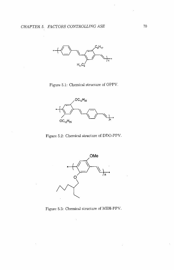
CHAPTER 5. FACTORS CONTROLLING ASE 70
Figure 5.1: Chemical structure of OPPV.
.OC„H 12' '25
OC12H25
Figure 5.2: Chemical structure of DDO-PPV.
OMe
0 7n~
Figure 5.3: Chemical structure of MEH-PPV.

CHAPTERS. FACTORS CONTROLLING ASE 71
groups which confer solubility on every other phenylene unit . OPPV is soluble in a range of organic solvents including xylene and toluene. Th in films of OPPV were formed by dissolving 30 mg of polymer in 1 ml of toluene and spin coating onto quartz substrates. The polymer was synthesised by Andreas Bleyer at the University of Sheffield via a W i t t i g reaction. The weight average molecular weight is about 5000 which is quite low compared to some other conjugated polymers (see MEH-PPV below). The photoluminescence quantum yield was measured and found to be 36 % in th in films [15]. This is higher than most dialkoxy PPVs which tend to have lower quantum yields and is consistent w i t h other work showing that polymers wi th dialkyl side groups tend to lead to higher quantum yields [16 .
The structure of poly(2,5-didodecyloxy p-phenylenevinylene co p-phenylene-
vinylene) (DDO-PPV) shown in figure 5.2 is also similar to PPV but in this
case the side chains are alkoxy groups and have 12 carbon atoms in each. The
side groups are substituted on alternate phenylene unit . The result of adding
alkoxy groups is to shift the luminescence to the red in comparison to PPV.
This polymer was synthesised by Andreas Bacher at Sheffield University via
a Heck reaction. The molecular weight of DDO-PPV is about 4800. Thin
films of D D O - P P V were formed by dissolving 30 mg of polymer in 1 m l of
toluene and spin coating onto quartz substrates. The quantum yield of th in
films of this polymer Wcis measured using the integrating sphere and found
to be 13 %.
The chemical structure of poIy(2-methoxy-5-(2'-ethylhexyloxy)-p-phenylene-
vinylene) (MEH-PPV) is shown in figure 5.3. MEH-PPV was supplied by
Covion in Germany and has a molecular weight of 1.6x10^. MEH-PPV
has asymmetrically substituted alkoxy side groups on the phenylene ring.
These groups confer solubility and also give the material a narrower energy
gap which shifts the luminescence to the red in comparison to PPV. Th in
films of M E H - P P V were formed by dissolving 5 mg of polymer in 1 m l of
CHAPTERS. FACTORS CONTROLLING ASE 72
chlorobenzene and spin coating onto quartz substrates. The photoluminescence quantum yield of a film of MEH-PPV spun f rom T H E was measured to be 30 %.
The novel polymers D D O - P P V and OPPV both have very low molecular
weights therefore very high quantities of polymer were required to form films.
However, when such large amounts of polymer were used, there were problems
w i t h solubility. Despite the large concentration, the greatest film thickness
that could be achieved was 60 nm. The solutions were filtered before they
were used. In comparison, M E H - P P V formed films between 50 and 200 nm
easily.
5,2.1 Absorption and Photoluminescence
The graph in figure 5.4 shows the absorption and photoluminescence (PL)
spectrum for OPPV (bold line) and for comparison the absorption and pho
toluminescence of P P V ( th in line). By comparison to PPV, the effect of the
alkyl chains i n PPV-co-DOctPV can be discussed. The absorption spectra
are very similar w i t h the peak close to 420 nm for both O P P V and PPV.
The PPV PL has some vibronic structure wi th peaks at 550 and 510 nm.
In comparison, the film PL of OPPV is broad, structureless and red shifted
by 40 nm. Another alkyl substituted PPV derivative is poly(2-butyl-5-(2'-
ethylhexyl)-l,4-phenylenevinylene) (BUEH-PPV) . BUEH-PPV is asymmet
rically substituted w i t h a butyl group on one side and an eight member alkyl
group on the other which gives more random packing. The PL of BUEH-
P P V [17] has similar vibronic structure to PPV wi th peaks at 550 and 520
nm. The broad red-shifted PL spectrum of the film of OPPV compared wi th
films of PPV and BUEH-PPV suggests that PL f rom films of OPPV is f rom
an inter molecular excited state such as an aggregate or excimer. This possi
b i l i ty has been investigated by using poor solvent mixtures. The PL spectra

CHAPTER 5. FACTORS CONTROLLING ASE 73
0.6 -
o 0.4
350 400 450 500 550 600 650 700 750 800 Wavelength (nm)
Figure 5.4: Photoluminescence and absorption spectra of OPPV (bold line)
and PPV ( thin line). ^
§ 0.08
350 400 450 500 550 600 650 700 750 800 Wavelength (nm)
Figure 5.5: Photoluminescence and absorption spectra of DDO-PPV fihn.

5- 300 <
^ 200
300 400 500 600 Wavelength (nm)
700 800
Figure 5.6: Photoluminescence and absorption spectra of MEH-PPV.
of films made f rom toluene, xylene (good solvents), cyclohexane (poorer sol
vent) and a mixture of methanol (poor solvent) and toluene in the ratio 6:5
have been measured [15]. I t was found that the PL spectra were broadened
and there was an increase i n the red emission for bad solvents. This could
be due to the formation of aggregates i n poor solvents. This result wi l l be
important when discussing the SLN results.
The graph i n figure 5.5 shows the absorption and photoluminescence spec
t r u m for DDO-PPV. The absorption spectrum is similar to the absorption
spectrum of OPPV. The peak is at 450 nm and i t is broad and featureless.
The PL spectrum however shows some vibronic structure w i t h peaks at 540
and 590 nm. There is also a long photoluminescence ta i l .
The graph in figure 5.6 shows the absorption and photoluminescence

CHAPTERS. FACTORS CONTROLLING ASE 75
spectrum for MEH-PPV. Both the absorption spectrum and the photoluminescence spectrum are red shifted compared to the two PPV derivatives discussed above. The red shift is due to the side groups which give the material a narrower energy gap. Alkoxy side groups also lead to a bigger red shift than alkyl groups, due to their inductive effects. The PL shows some vibronic structure w i t h peaks at 590 and 640 nm.
5.2.2 Spectral Line Narrowing
The graph in figure 5.7 below shows the result of exciting the OPPV film
w i t h high energy laser pulses. The excitation source was the th i rd harmonic
(355 nm) f rom the Nd-YAG laser described in chapter 4. A small peak is
seen at 535 nm when the films were excited w i t h 0.15 mJ, which indicates
that this is close to the threshold for line-narrowing. However when the
excitation energy was increased the film was photo-oxidised and only a PL
background was seen. The peak is substantially shifted f rom the peak of
the photoluminescence spectrum. No change in the emission spectrum of
D D O - P P V was seen when films were excited under the same conditions.
The graph in figure 5.8 shows the emission spectra of a film of M E H -
P P V measured at low (2 //J) and high (20 /iJ) excitation intensities. A t low
excitation intensities, the emission resembles that of the broad photolumi
nescence spectrum. As the excitation intensity is increased, the line-width of
the spectrum collapses and at higher intensities a narrow line wi th a width of
6 nm is observed. The narrow peak is close to the peak of the PL spectrum.
5.2.3 Discussion
The peak seen in the OPPV spectrum is assigned to stimulated emission,
however the narrowing is not complete and a substantial PL background can
s t i l l be observed. I t is now generally accepted in the literature that the mech-

CHAPTER 5. FACTORS CONTROLLING ASE 76
0.025
0.015
- 0.010
0.005
0.000
400 450 500 550 600 650 700
Wavelength/nm
Figure 5.7: Emission spectrum excited wi th 0.15 mJ f rom a film of OPPV.
600
400 H
Spectral Line Narrowing
Photoluminescence ^ 300
560 580 600 620 640 660 680 700 720 740 760
Wavelength! (nm)
Figure 5.8: Photoluminescence and spectral line-narrowing spectra of M E H -
PPV at 2 fiJ and 20 / i J respectively.
CHAPTER 5. FACTORS CONTROLLING ASE 77
anism of spectral line-narrowing is amplified spontaneous emission (ASE) as
described in chapter 3 and references [5-9]. For ASE to be produced, waveg
uiding in the polymer film is necessary to confine the optical field over a long
gain length [7]. I f the gain exceeds the losses, then stimulated emission is
produced. In order to fo rm a waveguide, the refractive index of the polymer
must be greater than that of both the substrate (quartz) and superstrate
(air). However, for a given thickness of polymer film there w i l l exist a cut-off
wavelength, above which light w i l l not be guided in the film. Equation 5.1
below shows how the cut-off thickness is related to the refractive indices of
the substrate, air and polymer for a given wavelength [18 .
X cutoff
27T^nj ---tan -1
\ nl-nl n1 ni
(5.1)
Here Ug is the refractive index of the substrate (for quartz 71^=1.46), uj is
the refractive index of the polymer film and is the refractive index of
the air ( n a = l ) . The polymer refractive index dispersion is not known but i t
is likely to be similar to that of MEH-PPV [19]. Conjugated polymers are
highly birefringent, as the polymer chains tend to align along the plane of
the film. This results i n a high in-plane refractive index in comparison to
the out of plane refractive index. For instance, in MEH-PPV the in-plane
refractive index at 620 nm is 1.91 and the out of plane refractive index is
1.65. From these data, the in-plane refractive index is likely to be between
1.8 and 2.0 at the emission wavelengths. I f these values are used in equation
5.1, a cut-off thickness of between 48 and 74 nm at 620 nm is calculated. The
cut-off thickness at 620 nm is therefore very close to the measured thickness
of the film. This shows that light at the peak of the gain spectrum (620
nm) may not be guided in the film and therefore no SLN is observed for the
D D O - P P V film. Weak SLN is seen in the OPPV film, but shifted to 535 nm,
below the cut-off for waveguiding. However, as this is not close to the peak

CHAPTERS. FACTORS CONTROLLING ASE 78
of the gain spectrum, the threshold is very high and such high excitation intensities tend to destroy the film. The effect of the thickness of the film and the cut-off thickness is discussed in more detail in chapter 7.
The calculations above show that the films were probably too th in to
support waveguide modes at the peak of the net gain. This either total ly
suppressed the SLN as in DDO-PPV or made i t extremely unstable as in
OPPV. However, thicker films could not be made as the molecular weight of
the materials is very low. Concentrations of approximately 30 m g / m l were
required to fo rm films 60 nm thick, however i f larger concentrations were used
the solutions would aggregate and very poor quality films were produced.
5.2.4 Aggregation
Another possible reason for the lack of SLN is that the polymer photophysics
is modified by aggregation, which can quench the luminescence. In order to
investigate the role of aggregation in OPPV, photoluminescence excitation
spectra (PLE) were measured.
The broad red-shifted PL spectrum of the films of OPPV compared wi th
the polymer i n solution and films of PPV shown in figure 5.4 suggests that
PL f r o m films of OPPV is f rom an inter-chain molecular excited state such
as an aggregate [15, 20 .
P L E spectra have been measured in films of OPPV. The spectra mea
sured at short detection wavelengths (corresponding to the short wavelength
ta i l of the PL spectrum) are shown in figure 5.9. Differences in the spectra
in the region of 350 nm and 450 nm indicate that the PL detected at longer
wavelengths is more strongly excited by longer wavelength excitation. This
is consistent w i t h some emission f rom aggregates. No further change of ex
ci tat ion spectrum was observed for longer detection wavelengths up to 740
nm.

CHAPTER 5. FACTORS CONTROLLING ASE 79
This is evidence that aggregation may play a role in quenching the lumi
nescence and spectral line narrowing in OPPV films.
600
500
Increasing Wavelength
= 300 -i Detection Wavelength
ZOO H
300 350 400 450
Wavelength (nm)
500
Figure 5.9: Photoluminescence excitation spectra for OPPV.
5.2.5 Summary From the three PPV derivatives that have been investigated, only MEH-PPV
is a suitable material for investigating the spectral line narrowing properties.
The main problem w i t h OPPV and DDO-PPV is their low molecular weight,
which affects the abihty to form good quality films which are thick enough
to support waveguide modes at the peak of the gain. In addition to this the
P L E measurements point to the formation of aggregates in OPPV. This leads
to the formation of traps, which may quench the luminescence and hinder
spectral-line-narrowing.

CHAPTERS. FACTORS CONTROLLING ASE 80
5.3 Factors which affect the ASE I n this section the factors which can affect the threshold for line-narrowing,
the Une-width and the spectral position are examined. M E H - P P V was chosen
for these measurements as i t is a well characterised polymer which exhibits
good line-narrowing in films. The mechanism for line-narrowing in this work
is assumed to be amplified spontaneous emission rather than a co-operative
emission process, as good waveguiding in the polymer film is seen to be
important for efficient line-narrowing and low thresholds. The importance
of waveguiding in the behaviour of the device is discussed in more detail in
chapter?. [7, 18].
5.3.1 Excitation Intensity
When assessing conjugated polymers for their use in amplification devices,
one important parameter to measure is the threshold intensity for spectral
line narrowing. This is defined as the power per unit area at which the
line-narrowing begins. This has been measured for a variety of polymers.
I n this work, the frequency doubled (532 nm) Nd:YAG laser w i th a pulse
w i d t h of 5 ns and a stripe length of 5 m m x 200 //m as described in chapter 4
was used. The graph in figure 5.8 shows the spectra measured at high and low
excitation intensities and the graph in figure 5.10 shows the f u l l wid th at half
maximum ( F W H M ) of the M E H - P P V luminescence spectrum as a function
of excitation energy. The emission spectrum at low excitation intensity (2
^J) resembles that of the photoluminescence spectrum w i t h a F W H M of 60
nm. As the excitation intensity is increased, the F W H M decreases rapidly
un t i l a narrowed emission of 8 nm is observed at 8 / i J . From this graph the
threshold for ASE is below 2 //J. Figure 5.10 also shows how the position
of the peak wavelength changes w i t h excitation intensity. A t low excitation
intensities, the peak wavelength is constant at 616 nm, however at an energy

CHAPTER 5. FACTORS CONTROLLING ASE 81
70
60
50
1 40
I 30
20
10 H
0
• •
1
• •
10 100
Excitation Energy nJ
• •
618
h 616 E c
614 | )
> 612 5
as Q.
610
608 1000
Figure 5.10: W i d t h (squares) and peak wavelength (circles) as a function of
excitation energy.
of 20 fiJ the peak of the ASE shifts towards higher energies. In total the
peak of the ASE moves by over 7 nm from 616 nm at low energies to 609 nm
at high energies.
A n interesting observation is that the peak position does not start to
change un t i l the incident energy is 20 fj,J, well above the threshold for ASE.
The observed shift may be due to the decrease in the decay time seen at high
excitation densities [4, 21]. Ultrafast spectroscopy of MEH-PPV has shown
that the emission spectrum immediately after excitation, shifts to the red over
the first tens of picoseconds following excitation [5]. This is due to the energy

CHAPTERS. FACTORS CONTROLLING ASE 82
migrat ion f rom excited polymer segments w i t h shorter conjugation lengths to more ordered, longer segments. Above the ASE threshold, emission occurs before the energy migration can take place, resulting in gain f rom the early, blue emission.
I t is also possible that photo-induced absorption, which has been as
signed to the formation of polaron pairs, could cause the position of the ASE
to move to higher energies. Yan et al. showed that there is competition be
tween the stimulated emission and photoinduced absorption [22]. They also
showed through time-resolved pump probe measurements that the stimulated
emission and the photoinduced absorption are likely to by due to different
species. Later work assigned the photoinduced absorption to interchain po
laron pairs [23]. The position of the ASE is determined by the position of
the maximum gain. This depends on factors such as the excited state and
ground state absorptions. The formation of polaron pairs is a non-linear pro
cess and therefore as the excitation intensity is increased, the formation of
polaron pairs could cause the position of the ASE to shift to higher energies.
Another possible explanation is that the observed blue shift on increas
ing excitation intensity can be accounted for by heating of the polymer. A
number of works have shown that heating of the polymer film results in a
blue shift of the photoluminescence spectrum [24-26]. Recent work, which is
discussed in more detail in chapter 6 shows that the ASE position shifts by
over 20 nm to the blue as the temperature of the film is increased f rom 98 K
to 298 K . The effective change in the temperature of the polymer film due
to the change of the excitation intensity, can be estimated f rom the specific
heat capacity of the polymer. The specific heat capacity can be assumed to
be similar to that of other organic polymers [27] and is taken here as 1.4
Jg~^K~^. The energy per pulse is about 500 //J, however only about half of
this l ight is absorbed and of the light absorbed only a maximum of 64% can
be converted to heat as f rom the quantum yield measurements 36% of the ab-

CHAPTERS. FACTORS CONTROLLING ASE 83
sorbed light is re-emitted. The energy per pulse which contributes to heating is therefore approximately 160 yuJ, the excited volume is 2xlO~^cm^ and the density is 1 g cm~^. This leads to a rise in temperature of the sample under these conditions of about 60 K . From the measurements in chapter 6 this would cause a change in the position of the ASE peak of about 6 nm. The actual change observed is 7 nm. This calculation shows that heating of the polymer film by increasing the excitation intensity could be an explanation for the blue shift of the ASE.
5.3.2 Angular Dependence of the Emission
I n order to measure the angular dependence of the ASE, the sample was
mounted i n a specially designed vacuum chamber which allowed the detector
to be rotated using a calibrated rotation scale. This measurement can be
used to examine the emission profile of the light, particularly whether the
emission is guided in the film or i n the substrate.
ASE spectra were measured between ± 2 0 ° perpendicular to the plane of
the film as shown in figure 5.11. The spectra were measured at a distance of
10 m m f r o m the edge of the film. This is the first measurement of the angular
dependence of the emission f rom a planar film. The integrated intensity at
each angle is plotted in the polar graph shown in figure 5.12. In order to
model the data, the emission profile is assumed to be similar to the diffraction
f rom a single slit of wid th a such that:
sind = - (5.2) a
where A is the wavelength of light, a is the effective w id th of the slit and 6
is the angle of the first min imum in the diffraction pattern. The intensity
profile of the emission f rom a single slit is given by

CHAPTER 5. FACTORS CONTROLLING ASE 84
Film
Substrate
Figure 5.11: Schematic diagram showing how the ASE was investigated as a
funct ion of angle (9).
m = 'sin{xy
X (5.3)
where x is a7rsin(9)/X, The data i n figure 5.12 has been fitted w i th the
funct ion described above and good agreement is achieved. The ASE was
at 620 nm, and the thickness of the film was 100 nm, therefore i t is clear
f r o m equation (5.2) that the slit width must be larger than the thickness of
the film. From the fitting parameters, an effective slit wid th of 1.2 ^ m was
obtained. This shows that the bound mode in the guide travels partly i n the
substrate and par t ly i n the air as well as in the polymer film.

CHAPTER S. FACTORS CONTROLLING ASE 85
10
Figure 5.12: Integrated intensity of ASE spectra as a function of emission
angle and fit to the data as described in the text.
5.3.3 Excitation Wavelength
The effect of excitation wavelength on the spectral position of the ASE has
been investigated for excitations in the range 385-590 nm. This is the first
measurement of the dependence of the ASE on the excitation wavelength in
conjugated polymers. For this experiment the nitrogen pumped dye laser was
used as described in chapter 4. Four dyes were used to span the range 385
n m to 590 nm. The dyes used were: PBBO (385-420 nm), coumarin 1 (436-
486 nm), coumarin 307 (480-530 nm) and coumarin 153 (517-590 nm). A l l
measurements were made at an excitation energy of 25 / i J as the excitation
intensity can affect the position of the ASE as discussed in section 5.3.1. The
excitation energy was controlled using neutral density filters.
The graph in figure 5.13 shows the peak positions as a function of exci-

CHAPTER 5. FACTORS CONTROLLING ASE 86
LU 624
616
350 400 450 500 550
Excitation Wavelength nm
600
Figure 5.13: Position of the peak of the ASE as a funct ion of excitation
wavelength.
ta t ion wavelength. The figure shows that wi th in experimental errors, there
is no change in the peak position wi th excitation wavelength.
I t has been proposed that the mechanism for ASE is similar to that of a
4-level dye laser system [28, 29]. I f this is the case then assuming that the
polymer was pumped in the T T - T T * band, excitation wavelength would not be
expected to have an effect on the position of the ASE, which is determined
solely by the energy of the vibronic states.
There has been some debate in the literature about whether the excitation
wavelength affects the optical properties of the polymer and i t has been shown
that i n cyano-substituted PPV the excitation and emission wavelength affect

CHAPTER 5. FACTORS CONTROLLING ASE 87
the decay dynamics [20]. The authors concluded that the luminescence was
f r o m both inter and intra molecular excitations. In contrast, Vacar et al. [30
investigated the effect of the pump wavelength on the decay dynamics of the
photo-induced absorption (PA) and stimulated emission of MEH-PPV and
found that in pristine samples the decay dynamics were identical regardless
of the pump wavelength. However, on an oxidised sample, they observed
that the stimulated emission signal decreased, and the PA signal increased
as the in i t i a l excitation intensity was increased. Other work by Harrison
et al. [31] showed that the quantum efficiency of pristine PPV samples was
constant w i t h excitation wavelength, but for oxidised samples a decrease in
the quantum eflBciency and also in the decay time was observed.
5.4 Gain and Loss Measurements
5.4.1 Experimental
L PoKmer Film
D
X Excitation Stripe
Figure 5.14: Schematic diagram of the gain measurement.
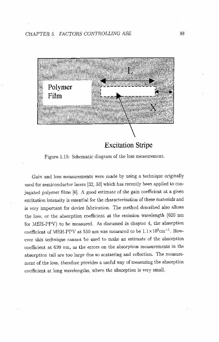
C H A P T E R S . FACTORS COJVTROLLJJVG ASE 88
Excitation Stripe Figure 5.15: Schematic diagram of the loss measurement.
Gain and loss measurements were made by using a technique originally
used for semiconductor lasers [32, 33] which has recently been applied to con
jugated polymer films [6]. A good estimate of the gain coefficient at a given
excitation intensity is essential for the characterisation of these materials and
is very important for device fabrication. The method described also allows
the loss, or the absorption coefiicient at the emission wavelength (620 nm
for M E H - P P V ) to be measured. As discussed in chapter 4, the absorption
coefficient of M E H - P P V at 550 nm was measured to be l . l x l O ^ c m " ^ How
ever this technique cannot be used to make an estimate of the absorption
coefficient at 620 nm, as the errors on the absorption measurements in the
absorption ta i l are too large due to scattering and reflection. The measure
ment of the loss, therefore provides a useful way of measuring the absorption
coefficient at long wavelengths, where the absorption is very small.

CHAPTERS. FACTORS CONTROLLING ASE 89
The diagram in figure 5.14 shows a schematic diagram of the gain measurement. The excitation beam was expanded using a divergent lens and then formed into a stripe using a cylindrical lens. The intensity of the laser stripe has a gaussian-like profile, therefore to keep the excitation intensity as constant as possible only a small central region of the stripe was used to excite the polymer film. A slit wi th a wid th of 3 m m was placed in the beam to determine the stripe length. The sample chamber was mounted on a translation stage which was then moved perpendicular to the excitation beam, so that the excitation stripe was effectively translated across the film as shown in figure 5.14. The effective length of the stripe changed but was always kept flush w i t h the edge of the film. The length of the stripe L was 3 m m and the pump intensity was 10 kWcm~^. As the distance moved by the sample chamber (D) increased, the length of the excitation stripe (X) decreased.
The loss measurement was made using the same set-up, however this time
the length of the excitation stripe was kept constant and by translating the
sample chamber, the stripe was moved away f rom the edge of the film. This
is shown in figure 5.15.
5.4.2 Theory
Assuming that the mechanism for spectral line narrowing is ASE, a relation
ship between the output intensity and the stripe length can be derived as
shown by both Mcgehee and Berggren inthe literature [6, 36]. This is also
a useful method for confirming that the emission is in fact ASE and not
superfluorescence, as has been proposed [34], as the data would not fit the
equation derived below i f the emission was due to superfluorescence. The
starting point for the derivation is the equations for spontaneous and for
stimulated emission.
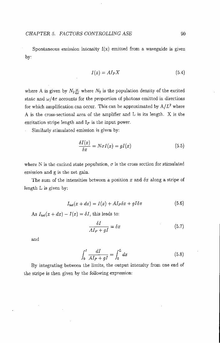
CHAPTERS. FACTORS CONTROLLING ASE 90
Spontaneous emission intensity I (x) emitted f rom a waveguide is given
by:
I(x) = AIpX (5.4)
where A is given by N2-^ where A'2 is the population density of the excited
state and U/4TT accounts for the proportion of photons emitted in directions
for which amplification can occur. This can be approximated by A / L ^ where
A is the cross-sectional area of the amplifier and L is its length. X is the
excitation stripe length and Ip is the input power.
Similarly stimulated emission is given by:
^ = Nal{x) = gl{x) (5.5)
where N is the excited state population, a is the cross section for stimulated
emission and g is the net gain.
The sum of the intensities between a position x and Sx along a stripe of
length L is given by:
Itotix + dx) = I{x) + AIp6x + gI6x (5.6)
As Itot{x + dx) - I{x) = 51, this leads to:
51
Alp + gl
and
= 5x (5.7)
dl / . = dx (5.8)
70 Alp + gl Jo
By integrating between the l imits , the output intensity f rom one end of
the stripe is then given by the following expression:

CHAPTER 5. E 4 C T 0 f i S CONTROLLING ASE 91
m = ^ ( e " ^ " - l ) (5.9)
The gain coeflficient was found by fitting equation 5.9 to the data. As the
gain term gl is large this can be approximated to:
/(A) = ^ (e»(^)') (5.10)
The loss coefficient is simply the absorption coefficient at the emission
wavelength. This is therefore related to the pump stripe length by:
/ = /oe(-"^) (5.11)
where a is the absorption coefficient.
5.4.3 Results
The graph in figure 5.16 shows the ASE spectra measured as the excitation
stripe length is increased. The spectra increase in intensity as the stripe
length is increased, as expected. I t is also interesting to note that the spectra
shift to shorter wavelengths at longer stripe lengths. The graph in figure 5.17
shows the integrated intensity of the ASE peaks as a function of stripe length.
The line is a fit to equation 5.9. From this fit the parameter A l p is found to
be 1.4x 10^ and the gain coefficient is 4 cm~^ The pump intensity was 10
kWcrn"^. The graph shows that equation 5.9 fits well up to a stripe length
of 1 m m . The deviation after this is caused by gain saturation. This occurs
because the light travelling in the waveguide is so strongly amplified that
a substantial f ract ion of the excitations are depleted. Any increase in the
pump stripe length, does not then produce an increase in the amplification,
in fact the gain coefficient is reduced when gain saturation takes place [35 .
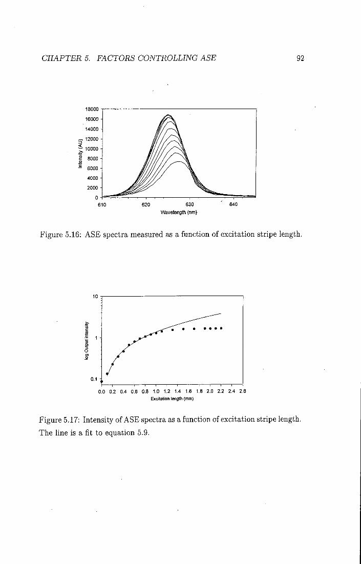
CHAPTER 5. FACTORS CONTROLLING ASE 92
18000
16000
14000
— 12000
^ 10000
- 6000 H
2000 -
610 620 630
Wavelength (nm)
Figure 5.16: ASE spectra measured as a function of excitation stripe length.
0.0 0.2 0.4 0.6 0.8 1.0 1.2 1.4 1.6 1.8 2.0 2.2 2.4 2.6 Excitation lengtti (mm)
Figure 5.17: Intensity of ASE spectra as a function of excitation stripe length.
The line is a fit to equation 5.9.

CHAPTER 5. FACTORS CONTROLLING ASE 93
0.0 0.1 0.2 0.3 0.4 0.5 0.6 0.7 0.8
Length (mm)
Figure 5.18: Integrated intensity of the ASE spectra as a function of distance
f r o m the pump stripe. The line is a fit to equation 5.11.
This result is similar to that measured by McGehee et al. [6] for the poly
mer poly[2-butyl-5-(2'-ethyl-hexyl)-l,4-phenylenevinylene] (BuEH-PPV) us
ing the same method. For a pump intensity of 1.2 kWcm~^ they measured
the gain to be 18 cm"^. This polymer is similar in structure to MEH-PPV
but has a higher photoluminescence quantum yield (62%) and is air sta
ble. Bergren et al. [36] used a similar method to determine the gain and
absorption coefficient in an alkyl substituted PPV doped into an oxidiazole
compound. They measured a gain of 1 cm~^ at 0.7 kWcm~^. These results
show that M E H - P P V can demonstrate high gain comparable to that of other
conjugated polymers.
The loss measurements are shown in figure 5.18. The graph shows the
integrated intensity of the ASE spectra as the pump stripe is moved away
f rom the edge of the film. The intensity decreases linearly as predicted by
equation 5.11. From this graph, the loss coefficient, i.e. the absorption coef-

CHAPTERS. FACTORS CONTROLLING ASE 94
ficient at 620 nm is found to be 10 cm~^ I n comparison, McGehee measured a loss coefficient of 44 cm~^ at 562 nm and Berggren et al. measured a loss coefficient of 0.6 cm~^ These measurements show that the loss coefficient can vary by over an order of magnitude, however the low loss coeflBcient coupled w i t h the relatively high gain measured for MEH-PPV show that this polymer is suitable for laser and amplification applications.
5.5 Conclusions
I n this chapter two novel PPV derivatives, OPPV and DDO-PPV have been
investigated. The emission spectra at high excitation densities were measured
and i t was found that no spectral line narrowing was observed in DDO-PPV
films. In films of OPPV, partial line-narrowing was observed at very high
pump intensities, however this d id not last more than a few seconds. The
cut-off thickness was calculated for these films based on an estimate of the
refractive index, and i t was found that the measured thickness of the film
was very close to the cut-off thickness. Thicker films could not be produced
due to the low molecular weight of these polymers. I t is therefore likely that
l ight at the peak of the gain spectrum could not be waveguided in the film,
and was therefore not confined over a gain length long enough for ASE to be
produced. The possibility of aggregation formation, which could quench the
excited state was also investigated. These materials have therefore not been
used for further amplification studies.
Measurements on the PPV derivative MEH-PPV showed that stable, nar
row emission was achieved at high excitation intensities. This polymer was
therefore used to probe the angular dependence of the emission, the effect
of excitation intensity and the effect of excitation wavelength. I t was found
that under high intensity excitation, the peak of the ASE moved to higher
energies (i.e. blue shifted). The possible reasons for this are: 1) the decrease

CHAPTERS. FACTORS CONTROLLING ASE 95
in the decay t ime of the excited state causes emission to occur eadier in
the migration process, 2) photoinduced absorption due to the formation of
polaron pairs causes the peak of the ASE to shift to shorter wavelengths as
the excitation intensity is increased, 3) heating of the polymer film leads to
a blue shift of the emission spectrum.
The angular dependence of the emission was modelled as the diffraction
f r o m a single slit. A n effective slit wid th of 1.2//m was calculated, showing
that the bound mode is guided in both the substrate and the polymer layer.
The measurements of the effect of excitation wavelength showed that there
was no dependence on the excitation wavelength over the range 380-590 nm.
The gain and loss coefficients have been measured for t h in films of M E H -
PPV. The gain coefficient was found to be 4 cm~^ at 10 kWcm""^ and the
loss or absorption coefficient at 620 nm was found to be 10 cm~^ These
measurements show that M E H - P P V has the potential to be used in solid
state diode lasers and for amplification devices.

BIBLIOGRAPHY 96
Bibliography B.H. Soffer and B.B. McFarland. Applied Physics Letters, 10:266, 1967.
'2] H . Kogelnik and C.V. Shank. Applied Physics Letters, 18:152, 1971.
3] N . Tessler, G.J.. Denton, and R.H. Friend. Nature, 382:695, 1996.
4] F. Hide, B . J. Schwartz, M . A . Diazgarcia, and A . J. Heeger. Chemical
Physics Letters, 256(4-5):424-430, 1996.
5] V . Doan, V . Tran, and B. J. Schwartz. Chemical Physics Letters, 288(2-
4):576-584, 1998.
6
r
8
9
11
12
M . D. McGehee, R. Gupta, S. Veenstra, E. K. Miller , M . A. DiazGarcia,
and A. J. Heeger. Physical Review B-Condensed Matter, 58(11):7035-
7039, 1998.
F. Hide, M . A . Diazgarcia, B . J. Schwartz, M . R. Andersson, Q. B. Pei,
and A . J. Heeger. Science, 273(5283):1833-1836, 1996.
G. J. Denton, N . Tessler, M . A. Stevens, and R. H . Friend. Advanced
Materials, 9(7):547, 1997.
C. Zenz, W . Graupner, S. Tasch, G. Leising, K. Mullen, and U . Scherf.
Applied Physics Letters, 71(18):2566-2568, 1997.
T . Q. Nguyen, V . Doan, and B. J. Schwartz. Journal of Chemical
Physics, 110(8):4068-4078, 1999.
C. Y . Yang, F. Hide, M . A . DiazGarcia, A . J. Heeger, and Y . Cao.
Polymer, 39(11):2299-2304, 1998.
X . Long, M . Grell, A . Malinowski, D . D. C. Bradley, M . Inbasekaran,
and E. P. Woo. Optical Materials, 9(1-4):70-76, 1998.

BIBLIOGRAPHY 97
13] C. Spiegelberg, N . Peyghambarian, and B. Kippelen. Applied Physics Letters, 75(6):748-750, 1999.
14] A . K . Sheridan, J . M . Lupton, I . D . W . Samuel, and D.D.C. Bradley.
Chemical Physics Letters, 322:51, 2000.
15] A. K . Sheridan, I . D . W. Samuel, A . Bleyer, and D. D. C. Bradley.
Synthetic Metals, 101(l-3):259-260, 1999.
16] N . C. Greenham, I . D . W . Samuel, G. R. Hayes, R. T . Phillips, Yarr
Kessener, S. C. Mora t t i , Holmesm A . B . , and R.H. Friend. Chemical
Physics Letters, 241(l-2):89-96, 1995.
17] M.R. Anderson. Synthetic Metals, 85:1275, 1997.
18] M . A. DiazGarcia, F. Hide, B. J. Schwartz, M . R. Andersson, Q. B. Pei,
and A . J. Heeger. Synthetic Metals, 84(1-3):455-462, 1997.
19] A . Boudrioua, P.A. Hobson, B.J. Matterson, W . L . Barnes, and I .D.W.
Samuel. Synthetic Metals, 111:545, 2000.
20] I . D . W . Samuel, G. Rumbles, C. J. CoUison, S. C. Mora t t i , and A. B.
Holmes. Chemical Physics, 227(1-2);75-82, 1998.
21] G. R. Hayes, 1. D . W . Samuel, and R. T. Phillips. Physical Review
B-Condensed Matter, 52(16):11569-11572, 1995.
22] M . Yan, L . J. Rothberg, F. Papadimitrakopoulos, M . E. Galvin, and
T . M . Mil ler . Physical Review Letters, 72(7):1104-1107, 1994.
23] M . Yan, L . J. Rothberg, E. W. Kwock, and T . M . Miller. Physical
Review Letters, 75(10):1992-1995, 1995.
[24] T . W . Hagler, K . Pakbaz, K . F. Voss, and A. J. Heeger. Physical Review
B-Condensed Matter, 44(16):8652-8666, 1991.

BIBLIOGRAPHY 98
25] K . Pichler, D . A. Halliday, D . D . C. Bradley, P. L . Burn, R. H . Friend, and A. B. Holmes. Journal of Physics-Condensed Matter, 5(38):7155-7172, 1993.
[26] J. W . Yu, M . Hayashi, S. H . L in , K. K . Liang, J. H . Hsu, W. S. Fann,
C. I . Chao, K . R. Chuang, and S. A. Chen. Synthetic Metals, 82(2):159-
166, 1996.
[27] A. Skotheim, R.L. Elsenbaumer, and J.R. Reynolds. Handbook of Con
ducting Polymers. 2nd edition, 1986.
28] B . Schweitzer, G. Wegmann, H . Giessen, D . Hertel, H . Bassler, R. F.
Mahrt , U . Scherf, and K . Mullen. Applied Physics Letters, 72(23):2933-
2935, 1998.
29] X . A. Long, A. Malinowski, D . D. C. Bradley, M . Inbasekaran, and E. P.
Woo. Chemical Physics Letters, 272(l-2):6-12, 1997.
30] D . Vacar, A. Dogariu, and A . J. Heeger. Chemical Physics Letters,
290(l-3):58-62, 1998.
31] N . T . Harrison, G. R. Hayes, R. T . Phillips, and R. H . Friend. Physical
Review Letters, 77(9): 1881-1884, 1996.
32] S. Hess, R. A. Taylor, J. F. Ryan, B. Beaumont, and P. Gibart. Applied
Physics Letters, 73(2):199-201, 1998.
33] K . L . Shaklee and R.F. Leheny. Applied Physics Letters, 18:475, 1971.
34] S. V . Frolov, M . Ozaki, W . Gellermann, M . Shkunov, Z. V . Vardeny,
and K . Yoshino. Synthetic Metals, 84(l-3):473-474, 1997.
'35] A. Yariv. Optical Electronics. Saunders College Publishing, 1991.

BIBLIOGRAPHY 99
36] M . Berggren, A. Dodabalapur, Z. N . Bao, and R. E. Slusher. Advanced Materials, 9(12):968, 1997.
Chapter 6
Effect of Temperature and Film Morphology on the Spectral Line-Narrowing in MEH-PPV
6.1 Introduction The temperature dependence of the absorption and photoluminescence of
conjugated polymers was first studied in MEH-PPV in 1991 [1] in M E H -
PPV polyethylene blends. Since then many studies, both theoretical and
experimental have investigated the temperature dependence of the optical
properties of conjugated materials [2-6]. These measurements lead to a good
understanding of some of the fundamental properties of these materials such
as the Huang-Rhys factor associated wi th different chain lengths [2] as well
as the effect of disorder on the system [1, 6]. In the context of controUing
the gain in conjugated polymers, a knowledge of how the materials behave
under changes of temperature is v i ta l for device fabrication, as i t leads to an
understanding of the gain mechanism. The ASE of th in films and the factors
affecting i t have been widely studied [7-11]. In particular factors such as the
100

CHAPTER 6. TEMPERATURE AND MORPHOLOGY EFFECTS 101
threshold for stimulated emission [7, 8, 12], the spectral position of the hne-narrowing [13], the film morphology [4, 12] and the film thickness [13] have all been recently investigated. Spiegelberg et al. recently investigated the effect of temperature on the threshold intensity for SLN in a PPV derivative [14 . Their work shows that the threshold for SLN has only a slight temperature dependence.
There has also been some evidence in the literature that the morphology
can affect the optical properties of the polymers. The effect of the spinning
solvent on the SLN for a range of polymers and solvents was investigated by
Hide et al. [12]. Their results showed that in MEH-PPV the threshold for
SLN was a factor of five times higher for films spin-coated f rom chloroben-
zene (CB-films) than for films spin-coated f rom tetrahydrofuran (THF-films).
They also found that the narrowed linewidth was only 50 nm wi th the CB-
films compared to 17 nm wi th the THF-f i lms. This was the first indication
that film morphology is a critical factor which determines the behaviour of
the SLN. Other work by Yang et al. [15] has shown that THF-f i lms have a
higher degree of crystallinity than CB-films, and Nguyen et al. showed that
the degree of order in polymer films can depend on the spinning solvent used.
This chapter presents a detailed study of the temperature dependence
of the spectral line narrowing, absorption and photoluminescence in films
of M E H - P P V . These are the first temperature dependent measurements of
SLN in M E H - P P V . The effect of film morphology was also investigated by
fabricat ing films spun f rom two spinning solvents ( T H F and CB) and compar
ing the temperature dependent absorption, PL and spectral line narrowing
results. The temperature dependence of the SLN was measured at the Uni
versity of Sheffield and I am grateful to Michael Redecker for his advice on
the equipment. A l l the absorption measurements were made by John Lupton
of Durham University.
The first part of this chapter presents the absorption, photoluminescence

CHAPTER 6. TEMPERATURE AND MORPHOLOGY EFFECTS 102
and SLN temperature dependence data. In the second part, the SLN data is compared to the absorption and photoluminescence data for the films spun f r o m CB and T H E and the results are discussed in the light of previous work in the literature. Finally, a comparison between the absorption and photoluminescence data is made which leads to interesting conclusions concerning exciton migration.
6.2 Experimental
T h i n films approximately 100 nm thick were prepared by spin-coating con
centrated solutions (5 m g / m l ) of MEH-PPV in either tetrahydrofuran (THE)
or chlorobenzene (CB) onto spectrosil substrates. A l l temperature dependent
measurements were carried out using an Oxford Instruments l iquid nitrogen
cooled cryostat.
The diagram in figure 4.3 shows the experimental set-up used for the
temperature dependent SLN measurements. For these measurements the
films were excited using a dye laser pumped by a pulsed nitrogen laser (337
nm) operating at 10 Hz. The laser dye coumarin 153 was used to give an
excitation wavelength of 523 nm. The energy incident on the sample was up
to 10 mJ per pulse. The beam was focused using a cylindrical lens into a
stripe of dimensions 200 mum x 5 mm. Emission was collected perpendicular
to the incident light.
Absorption spectra were measured by John Lupton in a Lambda 19 dual
beam spectrometer. For the photoluminescence measurements the 514 nm
line of an argon-ion laser was used to excite the samples. PL emission was
measured f rom the far side of the sample at close to normal incidence. The
positions of the 0-1 PL peaks (which are unaffected by self absorption) were
determined using a peak fitting programme by modelling the peaks as a
Gaussian convoluted w i t h a Lorentzian. The absorption spectrum was fitted
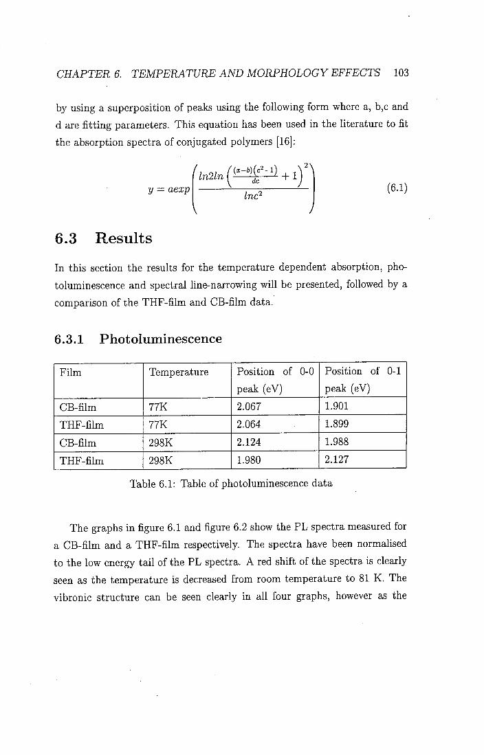
CHAPTER 6. TEMPERATURE AND MORPHOLOGY EFFECTS 103
by using a superposition of peaks using the following form where a, b,c and d are fitting parameters. This equation has been used in the literature to fit the absorption spectra of conjugated polymers [16]:
y = aexp Inc^
2 \
(6.1)
6.3 Results I n this section the results for the temperature dependent absorption, pho
toluminescence and spectral line-narrowing w i l l be presented, followed by a
comparison of the T H F - f i l m and CB-f i lm data.
6.3.1 Photoluminescence
F i l m Temperature Position of 0-0
peak (eV)
Position of 0-1
peak (eV)
CB- f i lm 77K 2.067 1.901
T H F - f i l m 77K 2.064 1.899
CB- f i lm 298K 2.124 1.988
T H F - f i l m 298K 1.980 2.127
Table 6.1: Table of photoluminescence data
The graphs i n figure 6.1 and figure 6.2 show the P L spectra measured for
a C B - f i l m and a T H F - f i l m respectively. The spectra have been normalised
to the low energy ta i l of the PL spectra. A red shift of the spectra is clearly
seen as the temperature is decreased f rom room temperature to 81 K. The
vibronic structure can be seen clearly in all four graphs, however as the

CHAPTER 6. TEMPERATURE AND MORPHOLOGY EFFECTS 104
SIK 15111 211k 271k
265k
14000
12000
10000
B 6000 i
Decreasing Temperature
540 560 580 600 620 640 660 680 700 720 740 760 780 Wavelength (nm)
Figure 6.1: Photoluminescence spectra f rom a CB-f i lm f rom 81K to 285 K
8000
6000
2? 4000
2000 H ; / / / / Decreasing Temperature
540 560 580 600 620 640 660 680 700 720 740 760 780 Wavelength (nm)
Figure 6.2: Photoluminescence spectra f rom a T H F - f i l m f rom 81 K to 281 K

CHAPTER 6. TEMPERATURE AND MORPHOLOGY EFFECTS 105
temperature is decreased, the vibronic structure becomes more pronounced. The high energy peaks are assigned to the 0-0 transition, and the second peak is assigned to the 0-1 peak of the TT to T T * transition. The peak positions are summarised in table 6.1. I n both films the relative intensity of the peaks changes. A t room temperature the high energy 0-0 peak is less intense than the 0-1 peak, however as the temperature is decreased the 0-0 peak becomes stronger than the 0-1 peak.
CB-film at 81 K
THF-film at 81 K V , >. 300
1.6 1.7 1.8 1.9 2.0 Energy eV
2.1 2.2 2.3
Figure 6.3: Photoluminescence f rom a CB-f i lm and a T H F - f i l m at 81 K and
285 K
The graph in figure 6.3 shows the PL spectra at 285 K and at 81 K for
films spun f r o m both T H E and CB. In order to compare the magnitude of
the shift of the absorption wi th temperature, PL and SLN spectra, all graphs

CHAPTER 6. TEMPERATURE AND MORPHOLOGY EFFECTS 106
have been converted to an energy scale and al l shifts are quoted in meV. The red shift as the temperature is decreased and the increase in the vibronic structure discussed earlier can be seen clearly.
Al though the peak positions are similar, there are significant differences
in the shape of the spectra for the two solvents. The spectra f rom the CB-
film are broader and show less vibronic structure than the spectra f rom the
T H F - f i l m . I t should also be noted that the integrated intensity of the spectra
at 81 K is greater than that of the spectra at room temperature. For further
analysis of this data the peak positions of the 0-1 transition are used for
comparison w i t h the SLN and absorption data so as to avoid any possible
effect of self-absorption on the 0-0 peak. The overall shif t w i t h temperature
of the 0-1 peak is 79 meV for THF-f i lms and 88 meV f rom CB-films.
6.3.2 Absorption
The data in figure 6.4 and figure 6.5 show the absorption spectra for a CB-f i lm
and a T H F - f i l m respectively. The graphs show clearly that as the tempera
ture is decreased the spectra sh i f t to longer wavelengths, as was observed for
the P L spectra. The overall shift of the spectra w i t h temperature is slightly
larger for the CB- f i lm than for the T H F - f i l m . This w i l l be discussed in more
detail later.
6.3.3 Spectral Line Narrowing
The graphs in figures 6.6 and 6.7 show the spectral line narrowing spectra as
a funct ion of temperature for a CB-f i lm and a T H F - f i l m respectively. These
spectra are narrow w i t h a f u l l wid th at half maximum ( F W H M ) of 19 meV
(7 nm) at room temperature. As the sample is cooled a red shift of the peak
position is observed. The small F W H M of 19 meV observed for the CB-f i lm
is much smaller than the value of about 159 meV previously reported by Hide

CHAPTER 6. TEMPERATURE AND MORPHOLOGY EFFECTS 107
< CO
I 1.5
20DK
Increasing Temperature
400 420 440 460 480 500 520 540 560 580 600
Wavelength (nm)
Figure 6.4: Absorption data for a CB-f i lm as a function of temperature (from
John Lupton) .
Increasing Temperature
400 420 440 460 480 500 520 540 560 580 600 Wavelength (nm)
Figure 6.5: Absorption data for a T H F - f i l m as a function of temperature
(f rom John Lupton) .

CHAPTER 6. TEMPERATURE AND MORPHOLOGY EFFECTS 108
1000
77K 117K 137K 177K 197K 237K
— 257K 277K
3 600
£ 400
620 630 640 650 Wavelength (nm)
660 670
Figure 6.6: ASE spectra as a function of temperature for a CB-f i lm.
1000
620
— 237K < 600
S 400
\ n/ t, i\ Ml
640 650 Wavelength (nm)
670
Figure 6.7: ASE spectra as a function of temperature for a THF- f i lm .

CHAPTERS. TEMPERATURE AND MORPHOLOGY EFFECTS 109
35
30
25
< 20 in
S 15 c
THF-flIm at 77 K CB-film at 77 K
CB-fllm THF-film at 298 K at 298 K
\ 1.88 1.90 1.92 1.94 1.96 1.98 • 2.00
Energy eV
Figure 6.8: ASE spectra for a T H F - f i l m and a CB-f i lm at 77K and 297K.
et al. [9]. This may be due to the improved quality of the polymer.
Figure 6.8 compares the SLN spectra measured for the CB-f i lm and T H F -
film spectra at 77 and 298 K . This graph is plotted on an energy scale so that
the shift of the spectra can be easily compared wi th shifts of the absorption
and P L spectra. The peak positions of the SLN spectra for the CB-f i lm shift
f r o m 1.959 at 298 K to 1.918 at 77 K, giving a tota l shift of 41 meV. The
T H F - f i l m peaks shift f rom 1.976 eV at 298 K to 1.908 eV at 77 K, giving a
tota l shif t of 68 meV. I t is interesting point to note is that the overall shift
of the C B - f i l m is smaller (41 meV) compared to the shift of the T H F - f i l m
spectra (68 meV). The figure also shows that the spectra f rom each film do
not coincide at either high or low temperatures. This is probably simply
due to the slight sample to sample variation in the peak position of the SLN.
However, this is small compared to the overall shift of the peak positions. I t is
also interesting to note that as w i th the PL spectra seen in figure 6.3, there is

CHAPTER 6. TEMPERATURE AND MORPHOLOGY EFFECTS 110
an increase in the integrated intensity as the temperature is decreased. This effect is much more pronounced in the CB-f i lm data. This figure also shows that while the F W H M of the T H F - f i l m SLN spectra is constant at 19 meV across the temperature range studied, the CB-f i lm spectra decrease f rom a F W H M of 28 meV at room temperature to 19 meV at 298 K . This decrease in the F W H M of the spectra is contrary to the disorder induced broadening seen in absorption and P L as the temperature is increased [3 .
6.3.4 CB-film data
The graph in figure 6.9 shows the peak positions of the SLN compared wi th
the 0-1 peak of the absorption spectra and the 0-1 peak of the PL spectra.
The absorption data has been shifted to lower energies by 0.355 eV to facil
itate comparison w i t h the SLN data. No shift has been applied to the PL
data. This figure shows clearly that the temperature dependence of the SLN
is different f rom that of both the absorption and the PL. The total change in
the absorption peak position across the temperature range is 86 rneV which
is more than double the change of the SLN peak position (41 meV). A similar
behaviour is seen in the lower panel where the SLN data is plotted against
the P L data. Here the change in the PL peak position is 88 meV which is
again much larger than the change in the SLN peak position. The figure also
shows that the peak positions of the SLN and PL only coincide at 220 K.
A t lower temperatures the SLN is blue-shifted f rom the PL and at higher
temperatures i t is red-shifted.
6.3.5 THF-data
The data for the T H F - f i l m SLN, absorption and photoluminescence are
shown i n figure 6.10. The temperature dependence is somewhat different for
the T H F - f i l m than that which was observed for the CB- f i lm discussed above.

CHAPTER 6. TEMPERATURE AND MORPHOLOGY EFFECTS 111
2.02
2.00 H I 1.98 o
0 ' CL
1 1.94 H
1.92
1.90 ^
1.98
1.96 c g I 1.94 H Q.
I 1.92 Q.
1.90
1.88
a) CB-film absorption and SLN
b) CB-film PL and SLN
50 100 150 200 250 Temperature K
300
Figure 6.9: MEH-PPV films spun from CB. Top panel: absorption (white
circles) and SLN (black circles. Bottom panel: photoluminescence (white
circles) and SLN (black circles).

CHAPTER 6. TEMPERATURE AND MORPHOLOGY EFFECTS 112
1.98
> 0) c g o
CL m 0)
CL
1.96 H
1.94
1.92 H
1.90
o
a) THF-film absorption and SLN
g 'to o
<u Q.
1.96
1.94
1.92 -
1.90 -
1.88
b) THF-film PL and SLN
O
o
• o • o
o
50 100 150 200 250 300 Temperature K
Figure 6.10: MEH-PPV films spun from THF. Top panel: absorption (white
circles) and SLN (black circles. Bottom panel: photoluminescence (white
circles) and SLN (black circles).
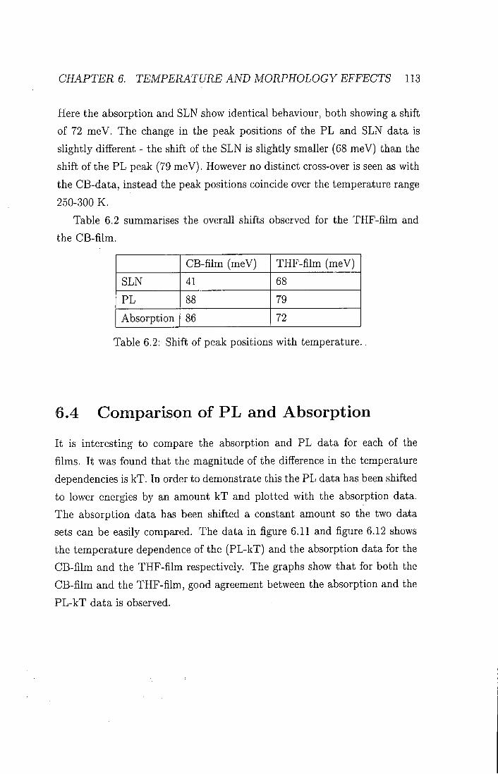
CHAPTERS. TEMPERATURE AND MORPHOLOGY EFFECTS 113
Here the absorption and SLN show identical behaviour, both showing a shift of 72 meV. The change in the peak positions of the PL and SLN data is slightly different - the shift of the SLN is slightly smaller (68 meV) than the shift of the PL peak (79 meV). However no distinct cross-over is seen as with the CB-data, instead the peak positions coincide over the temperature range 250-300 K.
Table 6.2 summarises the overall shifts observed for the THF-film and
the CB-film.
CB-film (meV) THF-film (meV)
SLN 41 68
PL 88 79
Absorption 86 72
Table 6.2: Shift of peak positions with temperature.
6.4 Comparison of PL and Absorption
I t is interesting to compare the absorption and PL data for each of the
films. I t was found that the magnitude of the difference in the temperature
dependencies is kT. In order to demonstrate this the PL data has been shifted
to lower energies by an amount kT and plotted with the absorption data.
The absorption data has been shifted a constant amount so the two data
sets can be easily compared. The data in figure 6.11 and figure 6.12 shows
the temperature dependence of the (PL-kT) and the absorption data for the
CB-film and the THF-film respectively. The graphs show that for both the
CB-film and the THF-film, good agreement between the absorption and the
PL-kT data is observed.

CHAPTERS. TEMPERATURE AND MORPHOLOGY EFFECTS 114
1.98
1.96
5 S 1.94 H
1.92
1.90 H
1.88
CB-fim
150 200 Temperature K
300
Figure 6.11: Position of the 0-1 peak of the PL (squares) (with kT subtracted
and absorption (circles) for a CB film.
1.98
THF-fim
§ 1.94
^ 1.92
1.88 - i |
50 100 150 200 Temperature K
250 300
Figure 6.12: Position of the 0-1 peak of the PL (squares) (with kT subtracted
and absorption (circles) for a THF film.
CHAPTER 6. TEMPERATURE AND MORPHOLOGY EFFECTS 115
6.5 Discussion 6.5.1 Film Morphology
The observation of a red-shift of SLN as temperature is decreased can be
understood to arise for the same reasons as the red-shift of absorption and PL
that has been studied in detail for PPV and MEH-PPV [1-5]. The decrease
in temperature freezes out torsions along the polymer backbone, increasing
the planarity of the polymer chains. This increases the extent of electron
delocalisation and reduces the energy of the 7 r — T T * transition. The position
of the SLN is determined by the gain and absorption in the sample. As both
the gain and absorption move to longer wavelengths at lower temperature,
so does the SLN.
There are a number of important observations from the data presented
here. The first is that the SLN peak positions for the THF-film show a differ
ent temperature dependence than that of the CB-film, while the absorption
and PL temperature dependencies for each film are very similar.
This is due to the differences in the conformation of the polymer molecules
and film morphology. Work by Hide et al. [9] has shown that the SLN
properties were strongly dependent on the solvent used for spin casting the
films. They showed that the threshold for spectral line-narrowing was a factor
of 5 higher for MEH-PPV films, i f the spinning solvent chlorobenzene was
used, compared with THF. Many factors aflfect the morphology of the films.
The boiling point of THF is only 65°C whereas that of CB is 132°C. This
means that the solvent evaporates more quickly from THF solution as the
film is being formed. The morphology of the polymer in solution is therefore
more easily transferred to the film. Experiments carried out by Nguyen et
al [17] confirmed this by showing that films keep some degree of 'memory' of
their conformation in solution when they are spin-coated to form films. CB
is said to be a 'better' solvent for MEH-PPV as there is more interaction

CHAPTER 6. TEMPERATURE AND MORPHOLOGY EFFECTS 116
between the solvent and the polymer [18, 19]. X-ray diffraction studies of MEH-PPV have compared films spin-coated from both THF and CB [15 . The results indicate that the morphology of the films is strongly dependent on the spinning solvent. Analysis of the results showed that films cast from THF were about 40% crystalline compared to 20% for CB-films.
Light scattering experiments [17] have shown that the hydrodynamic ra
dius (RH), which is a measure of the size of the polymer chains, was half the
size for solution of MEH-PPV in THF than it was for solutions in CB. In
addition to these measurements the spectra in figure 6.3 show that the PL
spectra from the CB-film are broader and less structured than those from the
THF-film. This indicates that the THF-film is more highly ordered than the
CB-film. Given this evidence it is likely that the difference in the morphol
ogy and therefore the interchain photophysics, will depend upon the spinning
solvent used to cast the films.
6.5.2 P L Q Y
The decrease in the intensity of the SLN and PL spectra with increasing
temperature, for example as seen in figures 6.1 and 6.6 is due to a decrease
in the photoluminescence quantum yield (PLQY). I t has previously been
shown that at low temperatures there is an increase in the intensity of the
PL in PPV [20, 21]. This was also seen in recent work by Spiegelberg et
al. [14] in which it was suggested that the increase in quantum yield at lower
temperatures accounts for the observed decrease in threshold intensity for
SLN in a PPV derivative. This is because the PLQY depends on the relative
rates of radiative and non-radiative decay [22]. At low temperatures the rate
of non-radiative decay is reduced, which increases the lifetime of the excited
state responsible for stimulated emission. This in turn causes an increase
in the gain. Although the absorption spectrum shifts with temperature, the

CHAPTER 6. TEMPERATURE AND MORPHOLOGY EFFECTS 117
films were excited just below the absorption peak, so that the total shift of the absorption spectra (around 30 nm) had very little effect on the optical density of the sample.
6.5.3 S L N Behaviour
The effect of the morphology on the films explains why the general tem
perature dependence may be different in THF-films from that in CB-films.
However the results also show that the shift of the SLN peak positions is
smaller than the shift of the PL peaks in both the films studied. There are
two possible explanations for these differences. The first is that the PL and
SLN occur from different sites or regions in the polymer film. The results of
Hide and Yang et al. [9, 15] have shown that SLN is more effective in more
crystalline films. This suggests that amplification may be particularly asso
ciated with crystalline regions of the films. In contrast the PL may be due
to the entire film including amorphous regions, which will have a different
temperature-dependence.
I t is also possible that other factors, such as the absorption of the sample
may have a different temperature dependence than that of the PL and SLN.
The peak of the SLN is determined by the net gain which is the difference be
tween the gain of the material and the loss. The loss is due to processes such
as ground state absorption, excited state absorption and scattering. I t has
been shown by pump probe measurements on PPV that the spectral shape
and position of the stimulated emission band depends on the overlap of the
gain spectrum and the photo-induced absorption band (due to excited state
absorption) [20, 23, 24]. These processes may have a different temperature
dependence from the PL, and hence the temperature dependence of the SLN
peak can differ from that of the PL. This will affect the SLN much more
strongly than the PL, as the measurement geometry is different. In the case

CHAPTER 6. TEMPERATURE AND MORPHOLOGY EFFECTS 118
of the SLN, the light is waveguided a few millimetres through the film before it is emitted. In contrast, in PL the light travels a maximum distance of the thickness of the polymer film (100 nm). Therefore absorption will affect the SLN spectrum more than the PL spectrum. However, the red-shift of ground state absorption observed as the temperature is decreased would be expected to cause a larger red-shift of SLN than of PL. In fact a smaller shift of the SLN than the PL is observed, which may be due to a counteracting effect from excited state absorption. In addition, temperature will affect the waveguiding properties of the polymer film as the refractive index and thickness of the polymer film changes.
6.5.4 P L and Absorption Data
The observation that PL-kT and the absorption data have the same tem
perature dependence in each of the solvents is extremely interesting. This
is probably due to the effect of thermal energy on exciton migration. Ex-
citons migrate from the polymer chain segments where they are created, to
longer chain segments on a range of timescales from femtoseconds to nanosec
onds [25-27]. The excitons will migrate until they are within an energy of
order kT of the lowest energy sites in the sample. This gives an additional
contribution to the temperature-dependence of the PL.
6.6 Conclusion
The temperature dependence of the photoluminescence, absorption and spec
tral Une-narrowing have been investigated for films of MEH-PPV spin coated
from both THF and CB. The results obtained are important both for a the
oretical analysis of the SLN but also for device fabrication. A red shift of
the SLN is observed when the temperature is reduced and the shift of the

CHAPTER 6. TEMPERATURE AND MORPHOLOGY EFFECTS 119
peak position is found to be smaller than the PL shift for both CB-films and THF-films. The differences in the behaviour of the films spun from different spinning solvents are due to the different morphology of the films.
There are two possible explanations for the smaller shift of the SLN peak
positions, compared to the absorption and PL. The first is that the SLN orig
inates from ordered sites whereas the PL is due to all sites, and the second
is that the position of the net gain is influenced by other processes such as
excited state absorption. These measurements show that the morphology of
the films is a very important factor which can determine the SLN character
istics. This understanding can be used to improve performance and will be
useful for the production of devices in the future.

BIBLIOGRAPHY 120
Bibliography 1] T. W. Hagler, K. Pakbaz, K. F. Voss, and A. J. Heeger. Physical Review
B-Condensed Matter, 44(16):8652-8666, 1991.
[2] J. W. Yu, M. Hayashi, S. H. Lin, K. K. Liang, J. H. Hsu, W. S. Fann,
C. I . Chao, K. R. Chuang, and S. A. Chen. Synthetic Metals, 82(2):159-
166, 1996.
3] K. Pichler, D. A. Halliday, D. D. C. Bradley, P. L. Burn, R. H. Friend,
and A. B. Holmes. Journal Of Physics-Condensed Matter, 5(38):7155-
7172, 1993.
4] A.K. Sheridan, J.M. Lupton, I.D.W. Samuel, and D.D.C. Bradley. Syn
thetic Metals, 111-112:531, 2000.
5] J.M. Lupton and I.D.W. Samuel. Synthetic Metals, 111:381-384, 2000.
6] M. Severin and O. Inganas. Journal of Chemical Physics, 105:8446,
1996.
7] V. Doan, V. Tran, and B. J. Schwartz. Chemical Physics Letters, 288(2-
4):576-584, 1998.
8] M . D. McGehee, R. Gupta, S. Veenstra, E. K. Miller, M. A. DiazGarcia,
and A. J. Heeger. Physical Review B-Condensed Matter, 58(11):7035-
7039, 1998.
, 9] F. Hide, M. A. Diazgarcia, B. J. Schwartz, M. R. Andersson, Q. B. Pei,
and A. J. Heeger. Science, 273(5283): 1833-1836, 1996.
10] G. J. Denton, N. Tessler, M. A. Stevens, and R. H. Friend. Advanced
Materials, 9(7):547, 1997.

BIBLIOGRAPHY 121
11] C. Zenz, W. Graupner, S. Tasch, G. Leising, K. Mullen, and U. Scherf. Applied Physics Letters, 71 (18):2566-2568, 1997.
12] F. Hide, B. J. Schwartz, M. A. Diazgarcia, and A. J. Heeger. Chemical
Physics Letters, 256(4-5) :424-430, 1996.
13] A.K. Sheridan, G.A. Turnbull, A.N. Safonov, and I.D.W. Samuel. Phys
ical Review B, 62(18), 2000.
14] C. Spiegelberg, N. Peyghambarian, and B. Kippelen. Applied Physics
Letters, 75(6):748-750, 1999.
15] C. Y. Yang, F. Hide, M. A. DiazGarcia, A. J. Heeger, and Y. Cao.
Polymer, 39(ll):2299-2304, 1998.
16] M. Liess, S. Jeglinski, Z. V. Vardeny, M. Ozaki, K. Yoshino, Y. Ding, and
T. Barton. Physical Review B-Condensed Matter, 56(24):15712-15724,
1997.
17] T. Q. Nguyen, V. Doan, and B. J. Schwartz. Journal of Chemical
Physics, 110(8):4068-4078, 1999.
18] L.E. Horsburgh. Private communication.
19] J. McMurry. Organic Chemistry. Brooks/Cole Publishing, 1984.
20] M. Yan, L. J. Rothberg, F. Papadimitrakopoulos, M. E. Galvin, and
T. M. Miller. Physical Review Letters, 72(7):1104-1107, 1994.
21] D.D.C. Bradley, R.H. Friend, and W.J. Feast. Synthetic Metals, 17:645,
1987.
22] N.S. Sariciftci, editor. Primary Photoexcitation in conjugated polymers:
Molecular Exciton versus Semiconductor Band Model. World Scientific
Co., 1997.

BIBLIOGRAPHY 122
23] W. Holzer, A. Penzkofer, S. H. Gong, A. Bleyer, and D. D. C. Bradley. Advanced Materials, 8(12):974-978, 1996.
24] G. J. Denton, N. Tessler, N. T. Harrison, and R. H. Friend. Physical
Review Letters, 78(4):733-736, 1997.
[25] G. R. Hayes, 1. D. W. Samuel, and R. T. Phillips. Physical Review B,
52(16):11569-11572, 1995.
26] I . D. W. Samuel, B. Crystall, G. Rumbles, P. L. Burn, A. B. Holmes,
and R. H. Friend. Synthetic Metals, 54(1-3):281-288, 1993.
27] B. MoUay, U. Lemmer, R. Kersting, R.F. Mahrt, H. Kurz, H.F. Kuffman,
and H. Bassler. Physical Review B, 50:10769, 1994.

Chapter 7
Tuneability of Amplified Spontaneous Emission
7.1 Introduction
The observation of stimulated emission in conjugated polymers using tech
niques such as transient absorption measurements [1-4] opened up the pos
sibility of using these materials in devices such as lasers. For this reason
a lot of work has been directed towards studying the gain process in order
to understand the mechanism behind it and the factors which affect it . As
discussed earlier, the dramatic narrowing of the emission spectrum is com
monly assigned to ASE. This process is seen in films which are thick enough
to support waveguide modes.
Control of the ASE is very important in the context of device fabrication.
There have recently been a number of works investigating the way in which
film morphology [5-7], excitation intensity (chapter 5) and temperature [8, 9
control the gain. However, the factors which determine the spectral position
of the emission are not well understood.
In this chapter the way in which the film thickness affects the peak posi-
123

CHAPTER 7. TUNEABILITY OF ASE 124
tion of the ASE is investigated. Through controlling the film thickness it is
shown that the spectral position of the peak of the ASE can be controlled,
demonstrating that gain can be tuned over a broad bandwidth. A theoretical
analysis is used to model the thin films as asymmetric waveguides. Through
this modelling of the waveguide modes the theoretical cut-off wavelengths
for guides of varying thicknesses are obtained. This information is used to
understand how film thickness affects the peak position of the ASE in these
experiments.
In addition a simple technique has been used to measure the waveguide
cut-off wavelength for the thin films and the results are found to compare
well with the theoretical calculations.
7.2 Theory
7.2.1 Spectral Location of the A S E
3 < 2000
Spectrai Line-narrowing
Photoluminescence
650 700 Wavelength nm
800
Figure 7.1: PL and spectral line-narrowing for MEH-PPV at 117 K.

CHAPTER 7. TUNEABILITY OF ASE 125
The main factor that determines the position of the ASE is the position
of the peak of the net gain spectrum. The net gain is determined by both the
material gain and the excited state and ground state absorption losses and
to a first order approximation is similar to the PL spectrum. However, the
peak of the ASE is generally located close to the 0-1 peak of the PL [10] as
shown in figure 7.1, indicating that the peak of the gain is not at the peak of
the PL spectrum, but is shifted to lower energies by ground state absorption.
Si
Absorption
s 0
Y\j Stimulated Emission
Figure 7.2: 4-level laser system.
Another way to approach this is to consider the polymer system to be
analogous to a 4-level dye laser system (figure 7.2) [10, 11]. In this approach
absorbed pump radiation excites the molecule from the ground state levels
50 to a higher vibrational level of the first singlet state Suit. The relaxation
from Siyib to is very fast (in the order of ps or faster) and radiationless.
Stimulated emission then occurs from the lowest level of the first singlet state
51 to a vibrational level in the ground state Soyib- This transition is to an

CHAPTER 7. TUNEABILITY OF ASE 126
unoccupied vibrational level rather than the populated ground state so that a population inversion can be achieved between the two states. This is a necessary condition for amplification to occur. The transition from the state to the 5*0^6 state corresponds to the 0-1 peak in the PL spectrum. Again the molecule quickly relaxes from the Sovib to state [12 .
7.2.2 A S E and Waveguiding
As discussed in chapter 3, the mechanism for spectral-line narrowing has been
assigned to ASE. In this process, the length over which amplified fight can
build up must be large enough for the light to be macroscopically amplified.
This process is helped by waveguiding in the film and i t has been found that
if the film is too thin to support waveguide modes, no ASE is observed [13 .
Hide et al. calculated a cut-off thickness (for light at 620 nm), below which
no ASE is seen [13]. However, as conjugated polymers have a broad spectral
emission and large material dispersion over the emission region, the cut-off
thickness is highly wavelength dependent. In order to investigate this further,
the ASE from six films of different thicknesses, close to the cut-off, have been
investigated.
As previously discussed, the structure used in these experiments make
simple one layer waveguides in which the substrate is the quartz or glass on
to which the polymer is spun, and the superstrate is air. The diagram in
figure 7.4 shows the structure of these waveguides. A guided mode can be
thought of as a beam of photons being totally internally reflected at both
interfaces and hence propagating down the waveguide.
7.2.3 Modelling
Using the theory described in chapter 3 the guided modes in a glass/MEH-
PPV/air waveguide were modelled. In order to account for the refractive

CHAPTER 7. TUNEABILITY OF ASE 127
>< 2.0 H
cc 1.8
550 600 650 700 750 Wavelength nm
800
Figure 7.3: In-Plane Refractive Index Dispersion of MEH-PPV. The line is
a fit to the data as described in the text.
index dispersion of MEH-PPV, measurements made by Safonov et al. [14
were used. Their results can be used with confidence as they used the same
batch of MEH-PPV as that used in this work, and the same spinning solvent
to form films. In their work thin films were formed by spin-coating on to
a microstructured diffraction grating with a period of 400 nm. The grating
acts as an ordered array of scattering centres, which results in constructive
interference of the light at an angle 9 to the normal to the plane of the guide.
This is the Bragg condition. The scattering angle 9, is wavelength dependent
and so the emission spectrum measured at a particular angle exhibits sharp

CHAPTER 7. TUNE ABILITY OF ASE 128
peaks at the Bragg scattered wavelengths that satisfy the relation:
rigsina — UaSinO = (7.1)
where N is the diffraction order (N=0 corresponds to Snell's law), A is the
grating period, a is the angle of the light in the guide to the normal to
the plane of the guide, n^ is the refractive index of the glass and Ua is the
refractive index of the air. The positions of these peaks were recorded at
different angles and these data were used to calculate the in-plane refractive
index between 580 nm and 800 nm. These data were fitted with the following
Sellmeier equation which is a standard way of fitting refractive index data:
no = Z , ^ ^ J ^ (7.2) 552 \
The refractive index data is shown in figure 7.3. As conjugated polymers are
highly birefringent materials, the out of plane refractive index is also required
to model the T M modes. Out-of plane refractive index data was measured
by Barnes et al. [15] using prism coupling.
7.3 Experimental Details
Six films of varying thickness of MEH-PPV were fabricated by spin-coating
a solution consisting of 5 mg of polymer dissolved in 1 ml of chlorobenzene.
Changing the spin speed between 1200 and 3000 rpm controlled the thick
ness of the polymer layer. Films of thickness between 46 nm and 154 nm
were obtained and were used in spectral-line narrowing experiments. For
these experiments the substrate used was glass microscope slides cut to 12
X 12 mm squares. Glass was used rather than fused silica which is used in

CHAPTER 7. TUNEABILITY OF ASE 129
other experiments as i t was found that the quality of the waveguide at the substrate edges, was better and therefore less scattering of the emitted light was observed. This was particularly important for the measurement of the cut-off" wavelength described in section 7.3.1.
The ASE spectra were obtained by exciting the front of the films with the
second harmonic of the Nd:YAG laser (532 nm) at 10 Hz. The energy per
pulse was about 10 /LiJ. A l l spectra were measured very close to threshold.
7.3.1 Measurement of Cut-off Wavelength
In order to measure the cut-off" wavelength a simple technique was used. The
films were painted black on the back of the substrate to suppress refiections
from the substrate/air interface. The film was held in a vacuum and excited
with a spot close to the edge of the film with the 488 nm line of an argon ion
laser. At detection angles greater than 20° to the plane of the film, the usual
MEH-PPV spectrum was measured. However when the detector was held
close to the plane of the film , shown by an angle 5 in figure 7.4, a narrow
feature was seen with a width of approximately 30 nm.
In the simple ray model of optical waveguiding there are two conditions
that need to be fulfilled in order for a guided mode to propagate in the film.
The first is that in order for light to be totally internaUy reflected the angle of
propagation must exceed the critical angle, 9c for the interface. The second is
that light of a certain wavelength can only propagate as a guided mode at one
angle. This angle decreases with wavelength. The equation for waveguide
modes is given as:
2ndkocos{9) = + + 2N'k (7.3)
Where n = refractive index of polymer, d= polymer film thickness, 9 =

CHAPTER 7. TUNEABILITY OF ASE 130
Air
MEH-PPV
Substrate
y 7 g|-„ • ^ — j » i JLL w F > — ^ ' > 1
Figure 7.4: The waveguide structure showing light that is totally internally
reflected and light travelling in the substrate parallel to the plane of the film.
angle of propagation, 0i and 2 are the phase change on reflection from
the polymer/air interface and polymer/glass interface respectively. N is an
integer and ko is the free space wave vector.
At the cut-off wavelength for the waveguide the angle for propagation will
be equal to the critical angle for the polymer/glass interface and therefore no
total internal reflection will occur. Instead some of the light will be lost from
the guided mode and will propagate in the substrate parallel to the plane
of the film as shown in figure 7.4 by the arrow running parallel to the poly
mer/substrate interface. Successive partial reflections from the polymer-glass
boundary will also contribute as sources to this substrate wave. For most
wavelengths emitted at the critical angle, these sources interfere destruc
tively and the accumulated substrate wave will be weak. However, for the
cut-off wavelength of the guide, the sources are correctly phased to interfere
constructively and so an enhancement is seen around this wavelength. For

CHAPTER 7. TUNEABILITY OF ASE 131
emission angles less than the critical angle the leaky modes will spread out into the substrate, and similar interference effects are seen for longer wavelengths. However the cut-off wavelength for the waveguide is that at which the peak is observed parallel to the plane of the film.
A similar technique has been used by the Cambridge group to determine
the refractive index dispersion of a polyflourene derivative [16 .
7.4 Results
7.4.1 Experimental Results
Figure 7.5 shows the ASE spectra obtained for six films of different thickness.
The spectra vary slightly in width as they were measured at incident energies
a little above the threshold for spectral line-narrowing.
The figure shows that the peak of the ASE spectrum is blue shifted as the
thickness of the film is decreased. For the thickest film (154 nm) the peak
of the ASE is at 623 nm and for the thinnest film (46 nm), the peak of the
ASE is at 592 nm. This shows that the peak of the ASE depends on the film
thickness. The interesting feature of this graph is the separation between the
three thickest and the three thinnest films. The peaks of the ASE for the
three thickest films are very similar, all positioned between 618 nm and 623
nm. However as the film thickness is reduced below this a large blue shift of
the ASE spectra is seen. This demonstrates that a broadband tuneability of
the ASE of 31 nm (25 THz) has been achieved. These results are explained
in section 7.4.2 through modelling of the waveguide modes.
7.4.2 Modelling Results
Figures 7.6 and 7.7 show the mode intensity for a 100 nm thick film at 590
nm and a 50 nm thick film at 590 nm. In figure 7.6 the sinusoidal distribution

CHAPTER 7 TUNEABILITY OF ASE 132
3.0
2.5
2.0 <
1.5
1.0
0.5
0.0
46 nm 55 nm 58 nm 76 nm 100 nm 154 nm
580 590 600 610 620 Wavelength nm
630 640 650
Figure 7.5: ASE spectra as a function of film thickness.
in the polymer and the exponential decay in the sub and superstrates can
be clearly seen. For this waveguide much of the mode intensity which corre
sponds to energy carried by the mode is in the polymer layer. Figure 7.7 has
the same mode relations but in this case the thickness of the polymer layer is
very close to the cut-off thickness for the waveguide at this wavelength. Here
very little of the mode is confined to the polymer and a lot of the energy is
in the substrate. The asymmetric nature of the graph is due to the different
refractive indices of the air and glass layers. The two figures show how the
proportion of the mode energy in the polymer layer changes as the cut-off
thickness is approached. For a polymer film well above the cut-off thickness
the mode is nearly symmetrical and mostly confined to the polymer layer.

CHAPTER 7. TUNEABILITY OF ASE 133
2.4 2.2 2.0 1.8
5 1.6 < 1.4 -t l - 2 -I 1.0 ^0.8
0.6 0.4 0.2 0.0
-1.0
Glass
-0.8
Polymer
Air
-0.6 -0.4 -0.2 0.0 0.2
Distance {]im)
0.4 0.6 0.8 1.0
Figure 7.6: Mode structure for 620 nm light in an MEH-PPV film lOOnm
thick.
2.4 2.2 2.0 -I 1.8
5 1.6 < 1.4
I 1.0 H ^0.8
0.6 0.4 0.2 0.0
-1
Glass
Polymer
Air
-0.8 -0.6 -0.4 -0.2 0.0
Distance (nm)
0.2 0.4 0.6
Figure 7.7: Mode structure for 620 nm light in an MEH-PPV film 50 nm
thick.

CHAPTER 7. TUNEABILITY OF ASE 134
0.0
a) exciting from the air side
III 1.0
\ b) exciting from glass side
0.5
1 i 1 1 1 1 1 1 1 r - — I 1 \ 1 0.0 0 10 20 30 40 50 60 70 0 10 20 30 40 50 60 70 80
Thickness (nm) Thickness (nm)
2.0
1.5
(U
0) T3 O
Transmission through the film Energy of Mode
— - Product of transmission and mode energy
Figure 7.8: Confinement factor for excitation from the air (a) and from the
glass side (b). For each graph the glass interface is at 0 nm and the air
interface is at 75 nm
As the polymer film thickness approaches the cut-off thickness for light of
a given wavelength, more of the mode energy is in the glass and the mode
becomes highly asymmetrical. At the cut-off thickness no fight of this wave
length will propagate in the polymer film as a bound mode. The relative
amount of energy can be evaluated using the confinement factor. Here this
is defined as the integral of the mode energy multipfied by the transmission
in the film. As the mode is asymmetric close to the cut off thickness, the
confinement factor should depend on which side of the waveguide is excited
with incident radiation. Figure 7.8 shows the mode energy in the film, the
transmission through the film and the product of these two quantities for

CHAPTER 7 TUNEABILITY OF ASE 135
samples excited both from the air side (a) and from the glass side (b). The area under the product of the transmission and the mode energy gives the confinement factor. This is found to be 50 for figure 7.8a and 60 for figure 7.8b. In order to calculate how the confinement factor affects the threshold for ASE, it is important to first calculate how the Fresnel reflections affect the intensity of the incident light. The Fresnel equation for unpolarized light at normal incidence is:
T = (7.4) {nt + TiiY
where T is the amount of light transmitted from the first medium of
refractive index rii to the second medium of refractive index For excitation
from the glass side, the calculation must be done in two steps to account for
the reflections from the air/glass interface and the glass/polymer interface.
Using the refractive index of the glass as 1.51, of the air as 1.0 and of the
polymer as 2.3 gives Igiass — 0.91 and IaiT= 0.84. The Fresnel reflections are
very similar in each case.
The threshold for ASE has been measured for excitation from both the
glass and the air side. For excitation from the air side the threshold is
3 ± 0 . 1 X 10"''' J and from the glass side i t is 2 .5±0.1 x 10~^ J. The important
observation is that the threshold for the glass side is slightly lower than for
excitation from the air side. This is predicted by the confinement factor
calculation.
Figure 7.9 shows the cut-off wavelength calculated as a function of thick
ness from equation 3.16 as described in chapter 3 for the first order TE and
T M modes. For a given thickness, only light of a wavelength shorter than
the cut-off wavelength can guide in the polymer layer. The figure shows that
light of 590 nm will be guided in films thicker than 50 nm whereas fight of
620 nm will only be guided if the polymer layer is thicker than 76 nm. These
results will be compared to the measured positions of the ASE peaks, and
are used to explain the observed blue shift in peak position as the thickness

CHAPTER 7. TUNEABILITY OF ASE 136
680
660
E c
i , 640 C
(U I 620
3
o 600
580
/ TE mode
/ T M ^ n ^ ^
40 60 80 100 120 Thickness nm
140 160
is decreased.
Figure 7.9: Calculated cut-off wavelengths
7.4.3 Comparison of Experimental and Theoretical Data
Figure 7.10 shows the peak positions of the ASE spectra taken from figure
7.5 as a function of film thickness and the theoretically calculated cut-off
wavelengths from figure 7.9. The figure shows that for the three thickest
films the position of the ASE is very similar (618 nm-623 nm) as described
earlier. However, the position of the ASE for the three thinnest films is very
close to the cut-off wavelength calculated by the model. Hence the position
of the ASE for thin films (< 76 nm) is determined by the cut-off wavelength

CHAPTER 7. TUNEABILITY OF ASE 137
680
5 620
TE mode
TM mode^
40 60 80 100 120 Thickness nm
140 160
Figure 7.10: Calculated cut-off wavelengths
for the guide whereas for thick films it is determined by the position of the
maximum gain density. Therefore by controlling the thickness of the film it
is possible to tune the emission wavelength of the ASE. In this work the ASE
has been tuned by 31 nm which corresponds to a bandwidth of 25 THz.
Tuning of the stimulated emission in conjugated polymer films has pre
viously been demonstrated in a laser cavity for example in the work of Ku
mar [18] in which tuning was achieved in a blend of a PPV derivative using
an external cavity resonator by the rotation of a grating . .Another approach
has been to use wavelength scale microstructure as in DFB lasers [19]. In this
work the emission was tuned by 43 nm by adjusting the period of the grat
ings. Here we achieve tuning without an external cavity or microstructure

CHAPTER 7 TUNEABILITY OF ASE 138
simply by changing the film thickness. The polarisation ratio of the ASE for thick and for thin films has been
measured. A calibrated linear polariser was placed between the film and the
CCD collection fibre. Emission spectra were measured for different angles of
the polariser and a sine function was fitted to the points. The polarisation
ratio is defined as the ratio of in-plane (TE) to out-of plane (TM) emission
intensity. For thin films (<76 nm) this ratio was found to be 98±2% and for
thick films (>140 nm) this was 75±2%. This shows that for thin films the
ASE is completely TE polarised and that all the Ught is guided in the zero
order TE mode. The lower polarisation ratio measured for thick films may
be due to both TE and T M modes being allowed to guide at the emission
wavelengths. Although figure implies that T M modes should not be guided,
it should be noted that there is a significant uncertainty of ±0.05 in the out-
of plane index data [15]. This results in an upper hmit of 620 nm for the
cut-off wavelength for the T M mode in a 150 nm thick film.
7.5 Measurement of Cut-off Wavelength
The cut-off wavelength for each of the six films used in the Une-narrowing
experiments was measured using a simple technique [16] described in section
7.3.1. The spectra obtained by this method are shown in figure 7.11.
When the emission was collected at 90it5°, narrow spectra with a width of
approximately 30 nm were obtained. The usual photoluminescenee spectrum
was observed when light was collected from the front face. The wavelength
of the peak of these spectra determines the cut-off wavelength for the guide
as explained in section 7.3.1. However, data could only be obtained for the
five thinnest films as the cut-off wavelength for the 154 nm film occurred at a
wavelength beyond the photoluminescence emission. As predicted by figure
7.11 the position of the peak moves to longer wavelengths as the thickness

CHAPTER 7. TUNEABILITY OF ASE 139
14000 ' \ 46nm
12000
10000 55 nm
76 nm
100 nm
560 580 600 620 640 660 680 700 720 Wavelength nm
Figure 7.11: Spectra measured using the cut-off wavelength technique.
of the film is increased. The spectra also get broader as the thickness of
the films is increased. This broadening is due to the shape of the refractive
index dispersion curve. Narrow spectra are only obtained when the change
in the refractive index is large with respect to wavelength (i.e. the gradient
is large). For light at angles less than the critical angle in the waveguide,
light will spread into the substrate as a leaky mode. The angle at which
the light is emitted into the substrate depends on the refractive index of
the MEH-PPV for that particular wavelength. Therefore, for large changes
in refractive index as a function of wavelength, light will be dispersed at
greater angles in the substrate and a narrow band emission spectrum will
be measured. As figure 7.3 shows, the gradient of the refractive index curve

CHAPTER 7. TUNEABILITY OF ASE 140
decreases with increasing wavelength, therefore spectra observed at longer
wavelengths are broader than those at shorter wavelengths.
7.5.1 Comparison of Theoretical and Experimental Cut
off Data
E c
c
(U
! "3 O
40 50 60 70 80 90 Thickness nm
Figure 7.12: Calculated cut-off wavelengths with measured wavelengths
Figure 7.12 shows the measured cut-off wavelengths (circles) and the cal
culated cut-off wavelength as a function of film thickness. Al l 5 points show
good agreement with the calculated values. This method for measuring the
cut-off wavelength has been used to calculate the refractive index dispersion
for a polyfluorene [16 .

CHAPTER 7 TUNEABILITY OF ASE 141
Film Film Thick Position of Measured Cut Calculated
ness (nm) ASE (nm) off A (nm) Cut-off A (nm)
1 46 592 592 588
2 55 602 603 602
3 58 606 612 607
4 76 618 645 644
5 100 621 703 702
6 154 623 NA 816
Table 7.1: Table of Results
A summary of the results in this chapter is shown in table 7.1.

CHAPTER 7. TUNEABILITY OF ASE 142
7.6 Conclusions In this chapter the effect of changing the thickness of the polymer layer on
the position of the ASE has been investigated.
The experiments show that by controlling the film thickness the position
of the ASE can be tuned by 31 nm which corresponds to a bandwidth of
25 THz. This is an extremely important result in the context of device
fabrication. By tuning the position of the ASE, the results show that gain
can be achieved over a broad range. This shows that conjugated polymers
have the potential to be used as broad-band optical amplifiers or as tuneable
solid state lasers.
By modelling the waveguide modes in the polymer film as simple asym
metric waveguides, a good understanding of how the thickness of the film
affects the position of the ASE, has been achieved. The waveguide modes
for two films, one with a thickness greater than the cut-off thickness and one
very close to the cut-off thickness were calculated. The cut-off wavelength
as a function of film thickness was also calculated. The results show that for
thick films (> 76 nm) the position of the ASE is determined only by the po
sition of the maximum gain, which depends on the ground and excited state
absorption losses. However for thin films, the position of the ASE is deter
mined by the cut-off wavelength for the waveguide, and is therefore highly
dependent on the thickness of the film. Hence the position of the ASE can
be tuned by controlling the thickness of the film.
In addition the cut-off wavelength has been measured for these films.
Good agreement with the calculated values was achieved, showing that mod
elling these structures as asymmetric waveguides is a reliable way of investi
gating the propagation of waveguide modes in the polymer waveguides.

BIBLIOGRAPHY 143
Bibliography
1] G.J. Denton, N. Tessler, N.T. Harrison, and R.H. Friend. Physics Review
Letters, 78:733, (1997).
2] E.S. Maniloff, A.V. Klimov, and D.W. McBranch. Physical Review B,
56:1876, 1997.
3] A. Dogariu, D. Vacar, and A.J Heeger. Physical Review B, 58:10218,
1998.
4] S.V. Frolov, M. Liess, P.A. Lane, W. Gellerman, Z.V. Vardeny,
M. Ozaki, and Yoshino K. Physics Review Letters, 78:4285, 1997.
5] T. Q. Nguyen, V. Doan, and B. J. Schwartz. Journal Of Chemical
Physics, 110(8):4068-4078, 1999.
6] C. Y. Yang, F. Hide, M. A. DiazGarcia, A. J. Heeger, and Y. Cao.
Polymer, 39(ll):2299-2304, 1998.
7] X. Long, M. Grell, A. Malinowski, D. D. C. Bradley, M. Inbasekaran,
and E. P. Woo. Optical Materials, 9(1-4):70-76, 1998.
8] C. Spiegelberg, N. Peyghambarian, and B. Kippelen. Applied Physics
Letters, 75(6):748-750, 1999.
9] A.K. Sheridan, J.M. Lupton, I.D.W. Samuel, and D.D.C. Bradley
Chemical Physics Letters, 322:51, 2000.
10] B. Schweitzer, G. Wegmann, H. Giessen, D. Hertel, H. Bassler, R. F.
Mahrt, U. Scherf, and K. Mullen. Applied Physics Letters, 72(23):2933-
2935, 1998.
11] X. A. Long, A. Malinowski, D. D. C. Bradley, M. Inbasekaran, and E. P.
Woo. Chemical Physics Letters, 272(l-2):6-12, 1997.

BIBLIOGRAPHY 144
12] F.P. Schaefer. Topics in Applied Physics. Springer-Verlag, 1973.
13] F. Hide, M. A. Diazgarcia, B. J. Schwartz, M. R. Andersson, Q. B. Pei,
and A. J. Heeger. Science, 273(5283):1833, 1996.
14] A.N. Safonov, M. Jory, B.J. Matterson, J.M. Lupton, M.G. Salt, J.A.E.
Wasey, W.L. Barnes, and I.D.W. Samuel. Synthetic Metals, in press.
15] A. Boudrioua, P.A. Hobson, B.J. Matterson, W.L. Barnes, and I.D.W.
Samuel. Synthetic Metals, 111:545, 2000.
16] T. Kawase, D.J. Pinner, and R.H. Friend. Synthetic Metals, 111:583,
2000.
17] A. Yariv. Optical Electronics. Saunders College Publishing, 1991.
18] N.D. Kumar, J.D. Bhawalkar, P.N. Prasad, F.E. Karasz, and B Hu.
Applied Physics Letters, 71:1999, 10997.
19] M. D. McGehee, M.A. Diaz-Garcia, F. Hide, R. Gupta, E.K. Miller,
D. Moses, and Heeger A.J. Applied Physics Letters, 72:1536, 1998.

Chapter 8
Efficient Energy Transfer in Perylene Dyes
8.1 Introduction Amplification was first observed in organic systems in the 1960s [1, 2]. More
recently the first observations of simulated emission in conjugated polymer
systems using transient absorption measurements [3-6], has lead to research
directed towards understanding the mechanism for the stimulated emission
and the factors which control the emission properties [7-10]. One goal of this
research is to fabricate an amplifier for the polymer optical fibre lietworks.
Polymer optical fibres are transparent at 650 nm therefore an amplifier in
a polymer optical fibre would ideally emit around 650 nm. However, it is
essential to make the amplifiers compatible with suitable pump lasers. This
can be achieved by using energy transfer, for instance a red emitting molecule
which has an absorption in the green can be doped into a system which ab
sorbs in the blue. This system could then be pumped using the commercially
available GaN (gallium nitride) laser. Energy would be transferred from the
blue absorbing host to the red emitting chromophore.
145

CHAPTERS. ENERGY TRANSFER 146
Energy transfer was first observed in 1922 by Carlo and Franck [11] using mercury and thalium vapour. More recent work has investigated the process in a range of organic systems relevant to electro-luminescence [12-18]. Using energy transfer in lasers has been shown to reduce the threshold for lasing, as the emission region is shifted away from the absorption region [17]. Work by Mattoussi has shown that by using a highly efficient acceptor material it is also possible for the quantum efficiency of the system compared to that of the pure host to be improved dramatically [13]. Energy transfer can also be useful in organic light emitting diodes to achieve white light emission [19.
Energy transfer can be used to control the emission wavelength and other
properties of the emission and it is therefore very important for the fabrica
tion of lasers, amplifiers, and light emitting diodes, that a detailed under
standing of the energy transfer mechanism is gained.
In this chapter the energy transfer properties of two conjugated organic
chromophores, lumogen orange and lumogen red, supplied by BASF, in Lud-
wigshafen, Germany were investigated. Thin films are made by doping the
chromophores into a host matrix of poly methyl methacralate (PMMA).
These dilute films can be treated as i f they are solutions. These materi
als are perylene derivatives and their chemical structures are shown in figure
8.1 and figure 8.2. They were first made as part of a series of perylene dyes
by Seybold and Wagonblast in the late 1980's [20]. At this time there was
great interest in synthesising perylene dyes for the fabrication of solid state
tuneable lasers [21, 22], The high photostabilities and high quantum yields
of these materials makes them ideal for laser applications [23]. These ma
terials have also attracted interest for their use in tuneable dye lasers [24
and in optically pumped sohd state lasers in PMMA, sol-gel and a compos
ite glass [25]. Laser emission of these dyes in a PMMA host has also been
observed [25] with laser emission at 578 nm for lumogen orange and 613 nm
for lumogen red. They are often referred to as perylene orange and perylene

CHAPTER 8. ENERGY TRANSFER 147
O 0
/ / w
Figure 8.1: Lumogen Red
Figure 8.2: Lumogen Orange

CHAPTERS. ENERGY TRANSFER 148
red in the literature. In this chapter the energy transfer dynamics in thin film blends of lumogen
orange and lumogen red, in the host matrix PMMA have been investigated.
In these blends, lumogen orange acts as the donor and lumogen red as the
acceptor. Measurements of the amplified spontaneous emission (ASE) are
made for blends of lumogen orange and lumogen red at different concentra
tions. In order to understand these results two different methods are used to
determine the rate of energy transfer between the dyes. The first method in
volves measuring the photoluminescence quantum yield of the luminescence
from the donor and the second uses time-resolved luminescence measure
ments which were carried out at Sheffield University. Results obtained using
these two methods are compared. The results of the measurement of the rate
of energy transfer are used to make an estimate of the excited state lifetime
of lumogen orange and hence to understand the concentration dependence of
the ASE results.
8.2 Theory
8.2.1 Energy transfer mechanisms
The term energy transfer simply means the transfer of energy from a donor
system to an acceptor system and can be achieved through vibrational, ro
tational, translational or electronic energy. However, it is more convenient
to limit this to electronic energy transfer where an acceptor is promoted to
a higher electronic state. This can be described by equation 8.1 [26]:
D* + A^D + A* (8.1)
Initially the donor D is in an excited state. This excitation is then passed
to the acceptor A and the donor is demoted to a lower electronic state.

CHAPTERS. ENERGY TRANSFER 149
One common type of energy transfer is radiative transfer, which is also referred to as trivial energy transfer [27]. In this process there is no direct interaction between the donor and acceptor. I t is a two stage process in which the donor, initially in an excited state, decays to a lower energy state with the emission of a photon. The photon is then absorbed by the acceptor, as shown below:
D* D + hu (8.2)
hu + A-^A* (8.3)
This type of energy transfer diff'ers from non-radiative transfer discussed
in the next section, in that there is no change in the donor emission lifetime
and the change in the emission spectrum can be fully accounted for in the
absorption spectrum of the acceptor.
8.2.2 Non-radiative Energy Transfer
Non-radiative energy transfer is more complicated than the 'trivial ' energy
transfer described above. This is a one step process in which there is some
direct interaction between the donor and the acceptor, without a photon
being produced. The process can only occur i f the initial and final states are
degenerate and if they are coupled by a donor-acceptor interaction.
An overlap integral (J) which defines the strength of the coupling between
the donor and the acceptor can be defined as:
J = I PD{u)eA{iy)^du (8.4)
Here, PD{^) is the photoluminescence of the donor and e^iv) is the extinction

CHAPTERS. ENERGY TRANSFER 150
spectrum of the acceptor. Both of these quantities are normalised to one on a wavenumber scale.
8.2.3 Forster (Long-range) Energy Transfer
Forster developed a formalism for energy transfer in which he only considered
transfer via dipole-dipole interactions [28, 29]. His theory assumes that the
energy transfer is much slower than the vibrational relaxation in the donor
and acceptor and applies only to systems in which the donor and acceptor
molecules are separated by at least 2 nm. He showed that the rate constant
for excitation transfer in which the initial and final states are coupled through
a dipole-dipole interaction is given by:
_ 9OOO/^/nlO0,, " - rDRn28ir^NAn^ ^ '
where p is an orientation factor, which for a solid solution with random
orientation of the donor and acceptor dipole moments is | , (pjo is the pho
toluminescence quantum yield of the donor which accounts for competition
for the energy transfer by other non radiative pathways. A''^ is Avagadro's
number, n is the refractive index of the system and J is the overlap integral.
TD is the natural radiative decay time of the pure donor, R is the average dis
tance between the donor and acceptor molecules and RQ is the characteristic
Forster radius, which is linked to the rate of energy transfer by:
' = - O [ R ) ^'-'^
Ro is the separation of the donor and acceptor at which the rate of intermolec-
ular energy transfer is equal to the sum of the rates for all other de-excitation
processes.

CHAPTER 8. ENERGY TRANSFER 151
As equation 8.5 shows, the rate of energy transfer depends on the overlap
integral J. In order to get efficient energy transfer, it is therefore necessary
to have good overlap between the donor emission spectrum and the acceptor
absorption spectrum. Figure 8.3 below shows the absorption and photolumi
nescence spectra for lumogen red and lumogen orange. In these experiments
the lumogen orange is the donor and lumogen red is the acceptor. This graph
shows clearly that there is good overlap between the donor emission spec
trum and the acceptor absorption spectrum and that this system is therefore
an interesting one to investigate in terms of energy transfer.
0.4 n
0.3 -
0.2 -
< 0.1 -g
a. k_ o 0.0 -CO
< 0.5 -
0.4 -
0.3 -
0.2 -
0.1 -
0.0 J
Absorption of Lumogen Orange
PL of Lumogen Orange
Absorpton of Lumogen Red
\ PL of Lumogen Red
450 500 550 600 650 700
Figure 8.3: Absorption (bold line) and photoluminescence (thin line) spectra
of films of lumogen orange (upper panel) and lumogen red, both doped in
PMMA (lower panel).

CHAPTER 8. ENERGY TRANSFER 152
A critical concentration C° is defined as the concentration at which the
energy transfer is 50% efficient. This is related to RQ through:
7.35 (8.7)
The diagram in figure 8.4 shows the energy transfer process between lumo
gen orange and lumogen red. The pump energy is absorbed by the lumogen
orange donor molecule, and is subsequently transferred to a lumogen red
acceptor molecule where the exciton radiatively recombines, emitting a pho
ton. The Forster energy transfer is shown by the dashed arrows between the
molecules. The solid arrows show the Pranck-Condon shift in each molecule.
LLz: Lumogen Orange
Luraogen Red
Figure 8.4: Forster transfer from lumogen orange to lumogen red molecules.
As equation 8.6 shows, the rate of energy transfer is a strong function of
the acceptor and donor separation (R^). In this chapter the rate of energy

CHAPTERS. ENERGY TRANSFER 153
transfer is investigated by controlling the concentration of the donor and the acceptor in the films and hence the intermolecular distance between them.
8.2.4 Least Squares Fitting
In order to quantify the energy transfer from donor to acceptor, i t is useful
to model the absorption and photoluminescence as a sum of the spectra
of the pure materials. In order to do this accurately, a least squares fitting
procedure was used. A least squares fit or linear regression is commonly used
to find the best fit line through a series of experimental points. A function
F(x) is assumed to be linearly related to G{x) through: F{x) = aG{x) + b
where a and b are constants [30]. In order to find the best way of describing
a spectrum as the linear combination of two other spectra, this form has to
be adapted to: F{x) = aG{x) + hH{x) where G{x) and H{x) are the two
spectra to be summed. By taking derivatives of this equation and setting it
equal to zero to minimize it , the following relation is obtained:
'=¥rTi i i^ (8.8) [%J - [99] [iT'h
.^9] - [99] [hh (8.9)
where the formalism [gf] is used to denote EQG{X)F{X) where n is the number
of points to be summed.

CHAPTER 8. ENERGY TRANSFER 154
8.3 Experimental
8.3.1 Film Preparation
Blends of lumogen red and lumogen orange were formed in the host matrix
poly methylmethacralate (PMMA). 250 mg of PMMA was dissolved in 1
ml of toluene. Lumogen red and lumogen orange were then added in the
quantities shown in table 8.1. The total quantity of lumogen orange and
lumogen red added was kept constant at 2.5 mg. Films approximately 3 //m
were formed by spin coating onto fused silica substrates at 1500 rpm. In the
measurements described later, the concentration of the dye molecules in the
PMMA host i.e. the number of moles per unit volume was required. This
was calculated by using the following relation:
C = pNa (8.10)
where C is the concentration in moldm"^, p is the density of the PMMA (1.1
gcm~^), M ^ is the molar mass (700 g for lumogen orange and 1102 g for
lumogen red) and N ^ is Avagadro's number.
Film Mass of red Mass of or % Red by % Orange Mass of
(mg) ange (mg) weight by weight PMMA
(mg)
A 0.15 2.35 6 94 250
B 0.25 2.25 10 90 250
C 0.375 2.125 15 75 250
D 0.75 1.75 30 70 250
E 1.0 1.5 40 60 250
Table 8.1: Film composition

CHAPTERS. ENERGY TRANSFER 155
8.3.2 Quantum Yield Measurements
The photoluminescence quantum yield (PLQY) was measured using an inte
grating sphere [31]. The PLQY is defined as:
^ _ K _ T _ No.photonsemitted (8 11) k Tr No.photonsabsorbed
where k is the total rate of decay, kr is the rate of radiative decay and r and
are the corresponding lifetimes. The rate of radiative decay is the decay rate
which is measured in the absence of any non-radiative decay. In practice non
radiative decay competes with radiative decay, therefore the measured rate is
the sum of radiative and non-radiative decay rates i.e. k=kii+kNR- In order
to measure the PLQY, the method described by de Mello [32] was employed
which was described in more detail in chapter 4. A CCD spectrograph was
used to collect the excitation and photoluminescence light. Two spectra were
recorded. The first was taken without a sample in the integrating sphere, to
measure the intensity of the laser light. The sample was then placed in the
integrating sphere in the path of the laser beam and the resulting spectrum
measured. This method avoids the need to measure the absorption of the
sample independently as the absorption is given by the drop in integrated
laser intensity of the spectrum with a sample compared to the integrated
intensity measured without a sample. The quantum yield of the sample is
then calculated by integrating under the PL spectrum to give the number of
photons emitted by the sample.
In order to calculate the rate coefficient for energy transfer, both the
PLQY for a lumogen orange film and the PLQY for the orange component
of the emission in the blends are required. The orange component of the
emission was calculated by measuring the PL from the blend in the inte
grating sphere. The red and orange component of the spectrum were then

CHAPTERS. ENERGY TRANSFER 156
calculated by using a least squares fitting routine described in section 8.2.4. The quantum yield of the orange component could then be calculated.
8.3.3 Time-resolved Luminescence IVEeasurements
The picosecond time resolved luminescence measurements were carried out on
the same set of samples using the streak camera set-up at Sheffield University.
The experimental set-up is shown in figure 8.5. The excitation source was the
second harmonic (490 nm) of a mode-locked Ti-sapphire laser which produced
100 fs pulses. The luminescence was collected with an achromatic lens system
and a double subtractive spectrometer (for spectral filtering of the emission
with 10 nm FWHM resolution) and detected with a 2 ps resolution streak
camera from DRS Hadland. Excitation light of 490 nm was used as the
lumogen red is nearly transparent at this wavelength, therefore most of the
pump radiation was absorbed by the lumogen orange.
8.4 Results - Evidence for Energy Trfinsfer
In this investigation, i t is first important to establish whether efficient energy
transfer is taking place. In order to do this, the absorption and photolumines
cence spectra for films with varying ratios of lumogen red to lumogen orange
were measured. The graph in figure 8.6 shows the absorption for films doped
with between 6% and 40% lumogen red. The graphs have been normahsed
to the peaks of the absorption as there was a slight variation in film thickness
due to slightly varying viscosities of the spinning solutions. The figure shows
strong vibronic features with peaks at 460 nm, 490 nm and 525 nm. These
peaks are identical to the vibronic structure in lumogen orange in figure 8.3.
The graph however shows an additional peak at 570 nm which changes in
strength with doping concentration. By comparison to the lumogen orange

CHAPTERS. ENERGY TRANSFER 157
Figure 8.5: Schematic diagrarn of the streak camera set-up at Sheffield Uni
versity

CHAPTER 8. ENERGY TRANSFER 158
0.6
0.5
0.4 A
0.2 H
0.1
0.0
RraAB% ram a 10% ram c 15 % ramoaos
0.12 -D.10 -
S 0.06
i— i—1 I 1 1 a 5 10 15 20 25 30 354045
Concartrabon of Lumogen Red(%)
Increasing Luraooen Red concenlration
300 350 400 450 500 550 Wavelength nm
600 650 700
Figure 8.6: Absorption spectra of blends of lumogen orange doped with
lumogen red. The insert shows the absorption at 570 nm as a function of
concentration.
Increasing Lumogen Red Concenration
:? 40
0 5 10 15 20 25 30 35 40 45
Concentration of Lumooen Red ra) Rim A 8% FilmB10% Film C 15 % Rim D 30 H Rim E 40%
550 600 650 700 Wavlength (nm)
750
Figure 8.7: PL spectra of blends of lumogen orange doped with lumogen red.
The insert shows the PL intensity at 540 nm as a function of concentration.

CHAPTERS. ENERGY TRANSFER 159
and lumogen red absorption spectra seen in figure 8.3, this peak is clearly due to the lumogen red absorption as the lumogen orange is transparent at this wavelength. As the concentration of the lumogen red is increased, the height of the peak at 570 nm also increases. The inset shows the absorbance at 570 nm against concentration of the lumogen red. A linear relationship is obtained as expected from the relation:
A = eCL (8.12)
where A is the absorption of the sample, e is the extinction coefficient, C is
the concentration and L is the path length through the sample.
The photoluminescence spectra shown in figure 8.7 for the same films were
measured using a flourimeter and exciting at a wavelength of 490 nm. The
graphs have again been normalised to the peak of the PL spectrum. Some
vibronic structure can be seen with peaks at 540 nra, 600 nm and 650 nm
clearly visible. By comparison to the pure lumogen red and pure lumogen
orange PL spectra in figure 8.3 the peak at 540 nm is assigned to the pure
lumogen orange emission. As the concentration of the lumogen red in the
blend increases the intensity of the peak at 540 nm decreases. The spectra
also shift slightly to longer wavelengths as the concentration is increased.
This is partly due to self-absorption. An increase in the absorption peak
at 570 nm as the lumogen red concentration is increased is shown in figure
8.6. This affects the PL spectra by shifting them to the red with increasing
concentration. However, a small shift is still seen at 650 nm, which is beyond
the absorption tail. This is likely to be due to aggregation of the lumogen
red. As the concentration is increased, the lumogen red molecules pack closer
together, increasing the interaction between them.
The absorption spectra have been fitted using the least squares fitting
routine described in section 8.2.4. Figures 8.8 and 8.9 show the results for

CHAPTER 8. ENERGY TRANSFER 160
Least Squares Rt
500 600
Wavelength (nm)
700
Figure 8.8: Absorption spectrum for film A (6%) (solid lines) and the results
of the least squares fitting routine (dotted line).
• niraE40% - Least Squares Fit
500
Wavelength (nm)
700
Figure 8.9: Absorption spectrum for film E (40%) (solid lines) and the results
of the least squares fitting routine (dotted line).

CHAPTER 8. ENERGY TRANSFER 161
550
- Rim A 9% - Least Squares Pit
600 650
Wavelength (nm)
Figure 8.10: Photoluminescence spectrum for Film A (6%) (solid line) and
the results of the least squares fitting routine (dotted line).
550
• Film E 4 0 % Least Squares Fit
3 40
12 30 H
600 660
Wavelength (nm)
700 750
Figure 8.11: Photoluminescence spectrum for Film E (40%) (solid line) and
the results of the least squares fitting routine (dotted line).

CHAPTER 8. ENERGY TRANSFER 162
fitting the 6% and 40% doped film. These fits give very good agreement with
the measured spectra. The ratio of lumogen orange to lumogen red is 16:1
for film A (6%) and 3:2 for film E (40%). These are the expected values
for these films given the mass of material used. Al l the least squares fitting
results are summarised in table 8.2.
Film % Red by %Absorption %Absorption %PL %P.L
weight (red) (orange) (red) (orange)
A 6 6 94 25 75
B 10 10 90 58 42
C 15 15 85 78 22
D 30 30 70 84 16
E 40 40 60 94 6
Table 8.2: Table of data
Figures 8.10 and 8.11 show the photoluminescence spectra for film A and
film E and the least squares fit obtained. The fit for film A is very good
for wavelengths longer than 580 nm. Below 580 nm the general shape of the
spectra are similar, but the intensity of the peak at 540 nm is not correctly
represented. This could be due to slight differences in the thickness of the
pure film compared to the thickness of the doped film. As there is a substan
tial overlap between the absorption and the emission for lumogen orange, self
absorption can affect the relative ratios of the 0-0 peak at 540 nm and the
0-1 peak at 580 nm. However, at higher concentrations of lumogen red, the
least squares fitted spectrum and the measured spectrum are very close, as
shown in figure 8.11 for film E. The values for the ratios of lumogen red and
lumogen orange obtained from the least squares fitting routine are shown in
table 8.2 for both absorption and photoluminescence. These data show that
the absorption spectra can be written as a linear sum of the absorptions of
the pure materials and that the ratios are similar to the ratio by weight of

CHAPTER 8. ENERGY TRANSFER 163
each material. In contrast, the photoluminescence data show that there is
more emission from the lumogen red, than would be expected if there were no
interaction between the two chromophores. This is clear evidence that effi
cient energy transfer occurs in this system. Figure 8.12 shows the absorption
and PL spectra for film E (40% lumogen red) compared to the pure lumogen
orange absorption and the pure lumogen red PL. The spectral characteristics
of the film are very closely matched to the pure absorption and PL spectra,
which is further evidence that efficient energy transfer is occurring in this
system.
Photoluminescence Absorption
=> 0.4 H
^ 0.3
< 0.2
400 500 600
Wavelength (nm)
700 800
Figure 8.12: Absorption and photoluminescence of film E (40%) (solid lines)
and absorption of pure lumogen orange and photoluminescence of pure lu
mogen red (dotted lines)..
8.4.1 Determination of Ro from the Overlap Integral
The Forster radius RQ can be determined from the overlap integral. As
equation (8.5) shows, the rate of energy transfer is proportional to the overlap

CHAPTER 8. ENERGY TRANSFER 164
integral which is given by equation (8.4).
Therefore a necessary condition for efficient energy transfer is good over
lap between the donor (lumogen orange) emission and the acceptor (lumogen
red) absorption. Figure 8.3 shows the absorption and photoluminescence for
both lumogen orange and lumogen red, offset for clarity. This figure shows
clearly that there is good overlap between the lumogen orange emission and
the lumogen red absorption. In order to calculate the overlap integral and
hence RQ, the extinction coefficient of the acceptor is required. The extinc
tion coefficient for lumogen red was measured by making a set of five films
of different optical densities. The absorption of these samples was then mea
sured in pairs (one in the sample and one in the reference beam of the lambda
19 absorption spectrometer), so as to minimise the reflection from the front
of the samples. The thickness of the samples was measured using the dektak
profileometer. A graph of change in absorption against change in thickness
for each pair of samples was then plotted and, using equation 8.12 an average
extinction coefficient of 5xl0'*cm~^ was calculated. This technique has been
used to calculate the absorption coefficient in conjugated polymer films and
is described in more detail in chapter 4.
By integrating under the product of the photoluminescence spectrum of
the donor and the extinction spectrum of the acceptor, the value of the
overlap integral was calculated to be 7.3xl0"'^^cm~'. Equation (8.5) and
(8.6) can be re-arranged to give the following relation:
Values of the 1.47 for the refractive index (n) and 0.95 for the PLQY
of the lumogen red (^D) were used in this equation to calculate the Forster
radius. The value of the Forster radius was found to be 7.0 ±1.0 nm. This
compares well with the work of Sharma [34] who measured a. Forester radius
of 6.5 nm.

CHAPTER 8. ENERGY TRANSFER 165
8.5 Results
8.5.1 ASE Results
The ASE spectra of blends with different lumogen red concentrations have
been measured. The spectra were measured at excitation intensities a little
above the threshold for ASE as shown in figure 8.13. This figure shows
that the peaks of the ASE spectra are in two groups. The spectra of the
film doped with the lowest concentration of lumogen red (6%) and the pure
lumogen orange film are observed at 580 nm, whereas the spectra of the films
with a higher concentration of lumogen red (10-40 %) are around 620 nm.
In order to show this data more clearly, the peak positions of the ASE
have been plotted as a function of lumogen red concentration (figure 8.14).
This graph shows clearly that there is a discontinuity in the spectral location
of the peak of the ASE which occurs at a lumogen red concentration of about
10%. At high doping levels the position of the ASE is constant at 620 nm,
whereas at low doping levels the ASE peak, is observed at close to 580 nm.
An important point to note is that the peak of the ASE spectrum from an
undoped lumogen orange film is at 580 nm and the peak of the ASE spectrum
for an undoped lumogen red film is observed at 620 nm. This shows that for
films doped with less than 10% lumogen red the ASE is due to the lumogen
orange molecules, whereas for higher concentrations energy transfer to the
lumogen red takes place and the ASE is therefore due to the lumogen red
molecules.
8.5.2 Determination of the Rate Coefficient
The absorption and photoluminescence measurements in this work have shown
that efficient energy transfer can take place between lumogen orange and lu
mogen red. The ASE results presented above show that when the position

CHAPTERS. ENERGY TRANSFER 166
40
A (6%) Pure Lumogen Orange
1(10%) 0 ( 1 5 % ) D(30%) E ( 4 0 % )
580 600 620
Wavelength nm
Figure 8.13: ASE spectra as a function of lumogen red concentration.
E 610
- ] 1-
5 10 15 20 25 30 35 40 45 50
Percentage Lumogen Red
Figure 8.14: Peak position of the ASE spectra as a function of lumogen red
concentration.

CHAPTERS. ENERGY TRANSFER 167
of the ASE peak is studied as a function of concentration, a discontinuity at about 10% is observed, fri order to understand why the position of the ASE peak depends on the concentration of the lumogen red in the blend, the rate of energy transfer has been measured between these two dyes using two different methods.
The first method involves measuring how the photoluminescence quan
tum yield (PLQY) of the donor (lumogen orange) changes as the lumogen
red concentration is increased. The second method uses the time-resolved
luminescence technique to measure the radiative lifetime of the lumogen or
ange as a function of lumogen red concentration. Both of these methods give
a measurement of the energy transfer coefficient (kg). The energy transfer
coefficient is the rate of energy transfer ksr per unit mole dm~^ and is there
fore related to the energy transfer rate through: HET = [Q]kg where [Q] is the
concentration in mol dm~^ of the acceptor. This relation shows that as the
concentration of the acceptor is increased, the distance between the acceptor
and donor molecules decreases leading to an increase in the rate of energy
transfer.
8.5.3 Method 1- Quantum Yield
Quantum yield measurements were made on films of lumogen red and lu
mogen orange using an integrating sphere as described in section 8.3.2. The
quantum 3deld for a pure lumogen orange film was found to be 85±5% and the
quantum yield for a pure lumogen red film was found to be 95±5%. The val
ues in the literature are 0.96 and 0.99 respectively [25]. The measured quan
tum yield value for lumogen orange may be lower than the literature value
as i t shows a tendency to form crystals due to its planar structure [23, 33 .
The quantum yield of a film is defined as in equation 8.11. In a blend
of lumogen orange and lumogen red, the lumogen red quenches the lumogen

CHAPTERS. ENERGY TRANSFER 168
orange luminescence. The rate of quenching is equivalent to the rate of energy transfer from lumogen orange to lumogen red. It is therefore possible to derive an equation for the rate of quenching in terms of the quantum jdeld of the lumogen orange and lumogen red and the concentration of the lumogen red in the blen'd.
From equation 8.11 the quantum yield of a pure lumogen orange film can
be written as:
k
where Krange is the radiative decay rate of the lumogen orange and k is the
total decay rate of the lumogen orange. The quantum yield of the lumogen
orange component of the emission from the blend can be written as:
ko k + kg[Q
where kg is the rate of quenching and [Q] is the concentration of the acceptor
(lumogen red in this case). By dividing equation 8.14 by equation 8.15 the
following relation is reached:
^ r ^ = i + h[Q] (8.16) TOTange
This equation shows that the energy transfer coefficient is directly related
to the quantum yield of the orange component of the emission in the blend,
the quantum yield of a pure orange film and the concentration of the lumogen
red in the film. These are all measurable parameters. The quantum yield of
the lumogen red and lumogen orange components of the photoluminescence of
the blends was measured. Figure 8.15 shows a plot of the ratio of the lumogen
orange quantum yield of a pure film to the lumogen orange quantum yield

CHAPTERS. ENERGY TRANSFER 169
in a blend as a function of the lumogen red concentration (often referred to as a Stern Volmer plot).
Equation (8.16) shows that a plot of the ratio of the quantum yield of the
pure orange to the quantum yield of the lumogen orange in the blends, as a
function of concentration will give a straight line graph with an intercept of
1 and a gradient of kg/k. This is believed to be the first demonstration of
this relation using thin solid films of small organics. ^
The figure shows that a straight line is observed as expected from equation
(8.16). The intercept of the graph is 0.7±0.2, close to the expected value of
1. The gradient of the graph is 1.93 ± 0.02 x lO^mol-Mm^ In order to
calculate kg the measured decay rate is required. Sharma has made time-
resolved luminescence measurements on blends of lumogen red and lumogen
orange [34]. He measured a value of 3.6 ns for the decay time of lumogen
orange. This corresponds to a decay rate of 2.8 x lO^s"^ By using this value
in equation (8.13), the energy transfer coefficient was found to be 5.4±0.2 x
10"s-^mol-^ dm^.
8.5.4 Method 2-Decay Rate
The second method for calculating the energy transfer coefficient involves
measuring the decay rate of the lumogen orange component of the blend.
When energy transfer occurs between a donor and an acceptor, the rate of
decay of the donor increases i.e. the lifetime decreases. This increase in the
rate is proportional to the rate of energy transfer. A similar method was
employed to measure the rate of energy transfer in lumogens by Sharma [34 .
The raw decay rate data is shown in figure 8.16. The data shows that as
the concentration of lumogen red in the blend is increased, the decay time
decreases, hence the decay rate increases. This data has been modelled using
a bi-exponential fit of the form:

CHAPTER 8. ENERGY TRANSFER 170
TJ 14
1 2 3 4
Molar concentration of Lumogen Red (mmol dm' )
Figure 8.15: Quantum Yield Measurements as a function of concentration.
(8.17)
Where r i and represent the lifetimes to be fitted and B i and B 2 are the
relative contributions of the individual lifetimes. The value of n corresponds
to the decay time of the sample, however a second exponential was required to
achieve a good fit and is due to defects in the sample such as inhomogeneity.
The fits for film A and film E are shown in figure 8.17.
In order to express the energy transfer coefficient in terms of measurable
quantities, equation 8.14 for the PLQY of a pure lumogen orange film can be
rewritten to give an expression for the quantum yield of the lumogen orange

CHAPTER 8. ENERGY TRANSFER 171
D30% C 15% B 10%
S 80
200 400 600 800 1000 Time ps
1200 1400
Figure 8.16: Raw time-resolved luminescence data for 5 films with different
doping levels.
component of the blend. This is given by:
^orange orange kb
(8.18)
where kt is the total decay rate of the blend. In the time-resolved lumines
cence measurements described above, the decay rate of the luminescence of
the blend kb is measured.
Equation 8.14 and equation 8.18 can then be substituted into the equation
8.16 which was derived for the quantum yield method in section 8.5.3. This

CHAPTER 8. ENERGY TK^NSFER 172
140
120
100
< 80
'E 60
40 H
20
0
Rim A (6%) Exponential Fit Decay Data
Film E 40%
200 400 600 800 1000 Time (ps)
1200 1400
Figure 8.17: Exponential fits to time-resolved data for films A (6%) and E
(40%).
gives a relation for the energy transfer coefficient in terms of measurable
parameters:
kb = k + kg [Q (8.19)
This equation shows that by measuring the decay rate of the luminescence
of the blend as a function of concentration, both the decay rate of the pure
lumogen orange (k) and the energy transfer coefficient (kg) can be derived.
The graph in figure 8.18 shows how the decay rate varies with concen-

CHAPTER 8. ENERGY TRANSFER 173
0 1 2 3 4
Concentration of Lumogen Red (mmol dm"^)
Figure 8.18: Decay rates measurements as a function of concentration.
tration of the lumogen red in the blend. The graph shows a hnear rela
tionship between the decay rate and the concentration. The gradient of the
graph also gives the coefficient of energy transfer, kg. From figure 8.18 kg
= 4.6 ± 0.2 X lO^^s-^morMm^. From the intercept k is 3.4 x lO^s'^ This
leads to a value of 2.9 ns for the radiative lifetime. This is close to the value
of 3.6 ns obtained by Sharma on a similar system [34 .
8.6 Comparison of Method 1 and Method 2
The absorption and photoluminescence data show that there is efficient
dipole-dipole energy transfer between lumogen orange and lumogen red. The
PLQY measurements and the time-resolved measurements of the blends of
lumogen orange and lumogen red show that the rate coefficient is between
4.6 ± 0.2 X 10 ^ and 5.4 ± 0.2 x lO^^s'^mol-^m^. I t is possible to compare
the data obtained using the two methods in one graph by translating the

CHAPTERS. ENERGY TRANSFER 174
time-resolved data into PLQY data as described below:
The ratio of the PLQY of the pure lumogen orange to the PLQY of the
lumogen orange component in a blend can be related to the rate of decay of
the pure lumogen orange and the rate of decay of the lumogen orange in the
blend by dividing equations (8.14) and (8.18). This gives:
^orange _ kb /„
6 ~ J ^ Yorange
Using this equation, the decay rates measured using method 2 were trans
lated into equivalent PLQY values. These values were plotted in figure 8.19
together with the PIQY values measured using method 1, so that the two
methods could be compared.
The graph in figure 8.19 shows that there is very good agreement between
the two sets of points and therefore the methods are both good ways of
determining the rate of energy transfer.
From these measurements the critical concentration and hence the Forster
radius can be calculated. The critical concentration is defined as the concen
tration at which the energy transfer is 50% efficient i.e when 2krb = K where
k is the decay rate in s~ . Substituting this into equation (8.19) gives:
kr = kg [Q] (8.21)
From this and the values for kr and kg calculated by using the two different
methods, the critical concentrations can be calculated. For method 1 the
value obtained for the critical concentration is 6.4 x 10~^M and for method
2 the value obtained is 7.5 x 10~^M.
From equation 8.7 RQ was found to be 8.5 nm for method 1 and 8.1 nm
for method 2. The average measured value for RQ is therefore 8.3 nm. This
is slightly higher than the value of 7.0 nm obtained from the overlap integral.
This may be due to errors in the measurements of the quantum yield and of

CHAPTER 8. ENERGY TRANSFER 175
X3 14
0 1 2 3 4 5
Molar cxjncentration of Lumogen Red (mmol dm' )
Figure 8.19: Quantum yield measurements as a function of concentration.
the decay time. There may also be donor-donor transfer which could result
in a larger value of RQ than that determined by the overlap integral [15 .
These results also compare well with work by Sharma [34] who measured the
decay time of the lumogen orange in lumogen orange/lumogen red blends in
PMMA. He obtained a value of 6.5 nm for the Forster radius. .
8.7 Discussion
The measurements of the energy transfer rate described above can be used
to understand why there is a discontinuity in the peak position of the ASE

CHAPTERS. ENERGY TRANSFER 176
as a function of concentration. The discontinuity seen in the ASE data may be due to competition between the energy transfer from the lumogen orange to the lumogen red and the stimulated emission mechanism. At low-concentrations of lumogen red, the rate of energy transfer is small as the inter-molecular distance is large. The stimulated emission decay rate is the preferred channel for decay and therefore ASE from the lumogen orange is observed. At higher concentrations the rate of energy transfer is also higher so .energy transfer becomes more efficient than stimulated emission as a decay pathway. The excitation will be transferred to the lumogen red before ASE is produced. Therefore for blends with high concentrations of lumogen red, the ASE peak is observed at the same wavelength as for the pure lumogen red film i.e. 620 nm.
The graph in figure 8.14 shows that the discontinuity in the position of
the ASE spectra occurs at a doping level of 10% (1 x 10~^M). Using this
value an estimate can be made for the lifetime of the stimulated emission.
At this concentration the stimulated emission rate is equal to the rate of
energy transfer. Using the value of 5.0 ± 0.2 x 10^^s~^mol~^dm^ for the rate
coefficient and a concentration of 1 x 10"^M, the stimulated emission rate is
4.9 ± 0 . 2 X 10^s~\ The stimulated emission lifetime is therefore 2.0 ns. This
is shorter than the spontaneous emission lifetime which has a value of 3.6 ns
measured by Sharma [34 .

CHAPTERS. ENERGY TRANSFER 177
8.8 Conclusion Thin films of blends of lumogen orange and lumogen red in a PMMA host
matrix have been made and through absorption and photoluminescence mea
surements i t has been shown that efficient energy transfer takes place from
the donor (lumogen orange) to the acceptor (lumogen red). This has been
successfully quantified by fitting the absorption and photoluminescence spec
tra as a sum of the pure lumogen orange and the pure lumogen red spectra.
The Forster radius was calculated using the overlap integral technique and
found to be 7.0 ±1.0 nm.
The ASE properties for blends of different concentrations of lumogen red
were investigated. The results show that the spectral position of the ASE
depends on the concentration of the lumogen red in the blend. For low
concentrations the peak of the ASE is observed at around 580 nm and for
high concentrations it is observed at 620 nm. The concentration of lumogen
red where the shift takes place is 10% = 1 x 10~^M.
In order to understand the energy transfer dynamics, the rate of energy
transfer has been measured using two different methods. The PLQY of the
lumogen orange component of the emission was measured as a function of
lumogen red concentration. Using this technique, the rate of energy transfer
was found to be 5.4±0.2x 10^^s~"^mol~^dm^ and from this the value of RQ was
calculated to be 8.5 nm. The second method involved measuring the decay
rate of the luminescence from the lumogen orange. Using this technique the
rate of energy transfer was found to be 4.6 ± 0.2 x 10^^s~^mol"Mm^. Prom
this the value of RQ was calculated to be 8.1 nm. These results show that
both measurements give a Forster radius close to the value obtained from
the overlap integral.
These values for the energy transfer rate were used to estimate the rate
at which the excited state is de-excited. The concentration at which the rate

CHAPTERS. ENERGY TRANSFER 178
of stimulated emission is equal to the rate of energy transfer, was shown by the ASE data to be 10%. This was used to estimate the rate of stimulated emission and was found to be 4.9 ± 0.2 x 10^s~^
These results show that energy transfer can be used effectively to control
the emission wavelength.
BIBLIOGRAPHY 179
Bibliography
1] B.H. Soffer and B.B. McFaxland. Applied Physics Letters, 10:266, 1967.
2] H. Kogelnik and C.V. Shank. Applied Physics Letters, 18:152, 1971.
3] A. Dogariu, D. Vacar, and A.J Heeger. Physical Review B, 58:10218,
1998.
4] E.S. Maniloff, A.V. Klimov, and D.W. McBranch. Physical Review B,
56:1876, 1997.
5] G.J. Denton, N. Tessler, N.T. Harrison, and R.H. Friend. Physics Review
Letters, 78:733, (1997).
6] S.V. Frolov, M. Liess, P.A. Lane, W. Gellerman, Z.V. Vardeny,
M. Ozaki, and Yoshino K. Physics Review Letters, 78:4285, 1997.
7] F. Hide, M . A. Diazgarcia, B. J. Schwartz, M. R. Andersson, Q. B. Pei,
and A. J. Heeger. Science, 273(5283):1833, 1996.
8] B. Schweitzer, G. Wegmann, H. Giessen, D. Hertel, H. Bassler, R. F.
Mahrt, U. Scherf, and K. Mullen. Applied Physics Letters, 72(23):2933-
2935, 1998.
9] X. Long, M . Grell, A. Malinowski, D. D. C. Bradley, M. Inbasekaran,
and E. R Woo. Optical Materials, 9(l-4):70-76, 1998.
10] V. Doan, V. Tran, and B. J. Schwartz. Chemical Physics Letters, 288(2-
4):576-584, 1998.
11] Carlo and Franck. Zeitschrift der Physik, 17:202, 1923.
12] S. E. Shaheen, B. Kippelen, N. Peyghambarian, J, F. Wang, J. D. Ander
son, E. A. Mash, P. A. Lee, N. R. Armstrong, and Y. Kawabe. Journal
Of Applied Physics, 85(ll):7939-7945, 1999.

BIBLIOGRAPHY 180
13] H. Mattoussi, H. Murata, C. D. Merritt, Y. lizumi, J. Kido, and Z. H. Kafafi. Journal Of Applied Physics, 86(5):2642-2650, 1999.
14] V. G. Kozlov, V. Bulovic, P. E. Burrows, M. Baldo, V. B. Khalfin,
G. Parthasarathy, S. R. Forrest, Y. You, and M. E. Thompson. Journal
Of Applied Physics, 84(8):4096-4108, 1998.
15] U. Lemmer, A. Ochse, M. Deussen, R. F. Mahrt, E. 0 . Gobel, H. Bassler,
P. H. Bolivar, G. Wegmann, and H. Kurz. Synthetic Metals, 78(3):289-
293, 1996.
16] G. Dicker, A. Hohenau, W. Graupner, S. Tasch, M. Graupner, A. Her-
metter, B. Schlicke, N. Schulte, A. D. Schluter, U. Scherf, K. Mullen,
and G. Leising. Synthetic Metals, 102(l-3):873-874, 1999.
17] R. Gupta, M . Stevenson, M. D. McGehee, A. Dogariu, V. Srdanov, J. Y.
Park, and A. J. Heeger. Synthetic Metals, 102(1-3):875-876, 1999.
18] A. Dogariu, R. Gupta, A. J. Heeger, and H. Wang. Synthetic Metals,
100(1):95-100, 1999.
19] R. S. Deshpande, V. Bulovic, and S. R. Forrest. Applied Physics Letters,
75(7):888-890, 1999.
20] G. Seybold and G. Wagonblast. Dyes Pigmants, 11:303, 1989.
21] S. Demmig and H. Langhals. Chemische Berichte-Recueil, 121(2):225-
230, 1988.
[22] A. Rademacher, S. Markle, and H. Langhals. Chemische Berichte-
Recueil, 115(8):2927-2934, 1982.
23] M. D. Rahn, T. A. King, A. A. Gorman, and I . Hamblett. Applied
Optics, 36(24):5862-5871, 1997.

BIBLIOGRAPHY 181
24] J. Ivr i , Z. Burshtein, E. Miron, R. Reisfeld, and M. Eyal. IEEE Journal Of Quantum Electronics, 26(9): 1516-1520, 1990.
25] M. D. Rahn and T. A. King. Applied Optics, 34(36);8260-8271, 1995.
26] A.A. Turro N.J. Lamola. Energy Transfer and Organic Photochemistry.
Interscience Publishers, 1969.
27] G. Gaviola and P. Pringsheim. Zeitschrift der Physik, 24:24, 1924.
28] T. Forster. Annalen der Physik., 2:55, 1948.
29] T. Forster. Discussions Faraday Soc, 27:7, 1959.
30] An Introduction to Error Analysis. Oxford University Press, 1982.
31] N. C. Greenham, L D. W. Samuel, G. R. Hayes, R. T. Phillips, Yarr
Kessener, S. C. Moratti, A. B. Holmes, and R. H. Friend. Chemical
Physics Letters, 241(l-2):89-96, 1995.
32] J. C. deMello, H. F. Wittmann, and R. H. Friend. Advanced Materials,
9(3):230 (4 pages), 1997.
33] S. Liu and L.L. Hench. Proceedings of the Society of Photo-optical In
strumentation, 1758:14, 1992.
34] P Sharma. Polymeric Thin Films for Integrated optics. PhD thesis,
1992.

Chapter 9
Conclusions
Lasers and amplifiers made from conjugated polymers have the potential to
revolutionise the communications industry. These semi-conducting materials,
which demonstrate strong amplification over a broad gain bandwidth are easy
to process and will be of great importance in future devices. For this reason,
the work in this thesis has investigated the factors which affect the gain in
conjugated polymers and perylene dyes. An investigation of the stimulated
emission characteristics of MEH-PPV, a red emitting polymer has shown that
the mechanism for the spectral line-narrowing (SLN) is amplified spontaneous
emission (ASE). The gain coefficient was measured to be 4 cm~^ and the loss
coefficient at 620 nm was 10 cm~^ Measurements also showed that there
was no effect of excitation wavelength on the position of the ASE.
The effect of temperature on the absorption, photoluminescence and ASE
characteristics of MEH-PPV films were also investigated. Films spun from
both THF and CB were compared and i t was found that the film morphology
affected the temperature dependence of the films. A smaller shift of the ASE
peak position compared to the PL for both THF and CB films was observed.
The two possible explanations for this are: (1) the ASE originates from
ordered sites whereas PL is due to all sites and (2) the position of the net
182

CHAPTER 9. CONCLUSIONS 183
gain is influenced by other processes such as excited state absorption.
I t was also shown that the absorption peak had the same temperature
dependence as the PL with the thermal energy kT subtracted. This is evi
dence that the excitons migrate until they are within kT of the lowest energy
sites in the sample.
I t was found that the spectral position of the ASE could be controlled
by 31 nm which corresponds to a bandwidth of 25 THz. This was achieved
by changing the film thickness close to the cut-ofF thickness for waveguiding.
Modeling of the waveguide modes in the asymmetric waveguide showed that
the cut-ofF thickness determines the wavelength of the ASE peak for thin
films, whereas for thick films the peak of the ASE is determined by the posi
tion of the maximum gain. A technique for measuring the cut-oflF thickness
of the polymer films was used and good agreement with the modeled data
was observed.
The process of energy transfer in organic films is potentially very useful in
that both the pump and the emission wavelength can be controlled. Efficient
energy transfer (Forster transfer) was observed between two perylene dyes
(lumogen orange and lumogen red). The energy transfer dynamics were
investigated in blends of these chromophores doped into the host matrix
PMMA. The position of the ASE was found to depend on the lumogen red
(acceptor) concentration. Below an acceptor concentration of 1 x 10~^M the
ASE was observed at 580 nm (originating from the lumogen orange) and
above the ASE was at 620 nm (originating from the lumogen red). The
energy transfer coefficient was measured using two different techniques to
be 5±0.2xl0^^mol~^dm^. This was used to estimate the rate of stimulated
emission at 4.9 x lO^s"^.
In the future work could focus on the mechanism for spectral line-narrowing,
as although the current opinion is that ASE is responsible for the dramatic
narrowing of the emission spectrum no work has showed conclusively that

CHAPTER 9. CONCLUSIONS 184
this is the case. Experiments would have to be carefully designed to dis
tinguish between ASE and spontaneous emission processes. It would also be
interesting to investigate energy transfer in more detail, especially as a mech
anism for controlling the emission wavelength, and this could be extended to
polymer systems.

Appendix A
Papers published as a result of this thesis
• Photophysics of an alkyl substituted poly(p-phenylenevinylene) A.K.
Sheridan, I.D.W. Samuel, A.Bleyer, D.D.C. Bradley,Synthetic Metals,
101 pp 259 (1999).
• Tuneability of the ASE in thin organic films. A.K.Sheridan, G.A.TurnbuU,
D.D.C.Bradley, I.D.W.Samuel, Synthetic Metals, in press
• The temperature dependence of the spectral line narrowing and photo
luminescence of MEH-PPV, A.K.Sheridan, J.M. Lupton, I.D.W. Samuel,
D.D.C. Bradley, Synthetic Metals 111-112 pp 533 (2000).
• The effect of temperature on the spectral line narrowing in MEH-PPV,
A.K. Sheridan, J.M. Lupton, I.D.W. Samuel, D.D.C. Bradley, Chemical
Physics Letters, 322 pp51 (2000)
• Tunability of amplified spontaneous emission through control of the
waveguide mode-structure in conjugated polymer films A.K. Sheridan,
185

APPENDIX A. PAPERS PUBLISHED 1 186
G.A. TurnbuU, A. Safonov, and W.L. Barnes, I . D. W. Samuel, Physical
Review B 62 pt l8 pp R11929 (2000)

Appendix B
Papers published from related work:
• Comparison of the electronic properties of poly[2-(2'-ethylhexyloxy)-
1,4-phenylenevinylene], prepared by different precursor pol3Tner routes,
S-C. Lo, A.K. Sheridan, I.D.W. Samuel, P.L.Burn, The Journal of Ma
terials Chemistry 9, No.9, pp 2165 (1999)
• Comparison of precursor polymer routes to and electronic properties of
phyenyacetylene derivatised poly[2-(2'-ethylhexyloxy)-l,4-phenylenevinylene],
S-C. Lo, A.K. Sheridan, I.D.W. Samuel, P.L.Burn. , The Journal of
Materials Chemistry, 10 pp 275 (2000)
• Effect of different precursor routes on the electronic properties of poly[2-
(2'-ethylhexyloxy)-l,4-phenylenevinylene] and poly[2-(2'-ethylhexyloxy)-
5-(phenylethynyl)-l,4-phenylenevinylene] S-C. Lo, A.K. Sheridan, I.D.W.
Samuel, P.L.Burn. Abstracts of papers of the American Chemical So
ciety, 218, No.Pt2, pp.551-POLY (1999).
• Tuning the opto-electronic properties of pyridine-containing pol3Tners
for light emitting devices, C. Wang, M. Kiliziraki, J.A. Macbride, M.
187

APPENDIX B. PAPERS PUBLISHED 2 188
R. Bryce, L.E. Horsburgh, A.K. Sheridan, A. P. Monkman, I.D.W.
Samuel. Advanced Materials, 12 No.3 pp 217 (2000).
• Conjugated polymer and dye molecules investigated by means of photo
thermal deflection spectroscopy, L.O. Palson, P.D. Wood, A.K.Sheridan,
I.D.W.Samuel. Chemical Physics Letters, submitted.