duravertical eco - s3.amazonaws.com · the 10.4-inch display has vertical soft-keys on the right...
TRANSCRIPT

Vertical Machining Center
DuraVertical 635 ecoDuraVertical 1035 eco
Machining Center
DuraVertical eco
目目Features of machineMechanismHigh precisionMachining abilityMAPPS ⅣDiagram/Interference diagramDiagramsSpecifications

Vertical Machining Center
A new vertical machining center that has established new world standards for
cost performance and high quality
DuraVertical 635 ecoDuraVertical 1035 ecoMori Seiki provides the DuraVertical eco Series packed with the
latest technologies at affordable prices for customers who seek
high quality and fl exibility to succeed in the highly competitive and
increasingly global market. The DuraVertical eco Series is ready to
support your production with its superior performance.
● Photo: DuraVertical 635 eco● Actual nameplate layout may differ from the photo.● Figures in inches were converted from metric measurements.
● Our model is 170 cm (5.6 ft) tall.
3DuraVertical 635 eco/DuraVertical 1035 eco
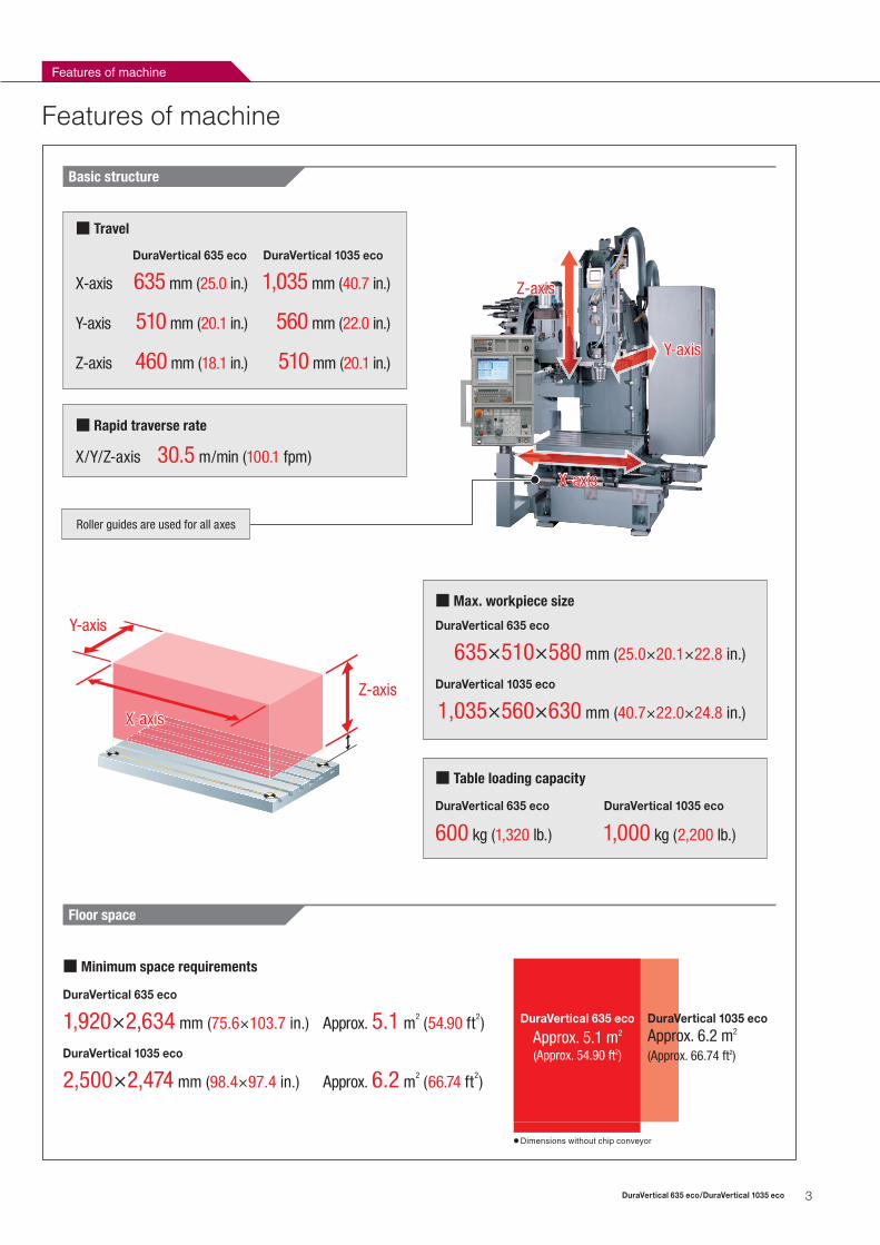
Basic structure
■ Rapid traverse rate
X/Y/Z-axis 30.5 m/min (100.1 fpm)
■ Table loading capacity
600 kg (1,320 lb.) 1,000 kg (2,200 lb.)
635×510×580 mm (25.0×20.1×22.8 in.)
■ Max. workpiece size
■ Travel
X-axis 635 mm (25.0 in.) 1,035 mm (40.7 in.)
Y-axis 510 mm (20.1 in.) 560 mm (22.0 in.)
Z-axis 460 mm (18.1 in.) 510 mm (20.1 in.)
DuraVertical 635 eco DuraVertical 1035 eco
DuraVertical 635 eco
DuraVertical 1035 eco
1,035×560×630 mm (40.7×22.0×24.8 in.)
Floor space
Features of machine
DuraVertical 635 eco DuraVertical 1035 eco
Roller guides are used for all axes
X-axis
Z-axis
Y-axis
X-axis
Z-axis
Y-axis
■ Minimum space requirements
Approx. 5.1 m2 (54.90 ft2)1,920×2,634 mm (75.6×103.7 in.)
DuraVertical 635 eco
DuraVertical 1035 eco
2,500×2,474 mm (98.4×97.4 in.) Approx. 6.2 m2 (66.74 ft2)
DuraVertical 635 eco
Approx. 5.1 m2 (Approx. 54.90 ft2)
DuraVertical 1035 ecoApprox. 6.2 m2
(Approx. 66.74 ft2)
● Dimensions without chip conveyor
Features of machine
4 DuraVertical 635 eco/DuraVertical 1035 eco
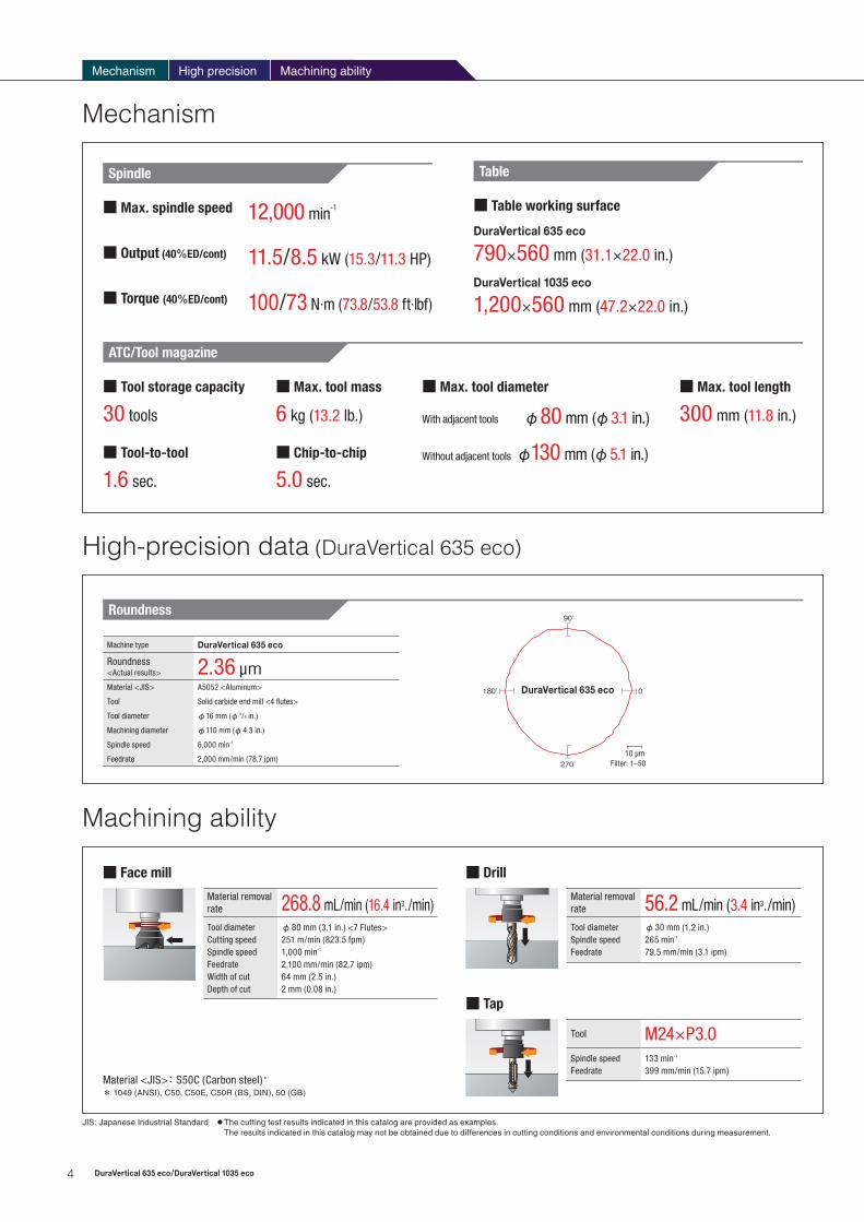
Table
Mechanism High precision
■ Max. spindle speed 12,000 min-1
■ Output (40%ED/cont) 11.5/8.5 kW (15.3/11.3 HP)
■ Torque (40%ED/cont) 100/73 N·m (73.8/53.8 ft·lbf)
Mechanism
■ Table working surface
790×560 mm (31.1×22.0 in.)
DuraVertical 635 eco
DuraVertical 1035 eco
1,200×560 mm (47.2×22.0 in.)
ATC/Tool magazine
■ Tool storage capacity
30 tools
■ Max. tool mass
6 kg (13.2 lb.)
■ Max. tool diameter
φ80 mm (φ3.1 in.)With adjacent tools
φ130 mm (φ5.1 in.)Without adjacent tools
■ Max. tool length
300 mm (11.8 in.)
■ Tool-to-tool
1.6 sec.
■ Chip-to-chip
5.0 sec.
Spindle
High-precision data (DuraVertical 635 eco)
Machining ability
Roundness
180̊ 0̊
90̊
270̊ Filter: 1–50
DuraVertical 635 eco
10 μm
Machine type DuraVertical 635 eco
Roundness <Actual results> 2.36 μmMaterial <JIS> A5052 <Aluminum>
Tool Solid carbide end mill <4 flutes>
Tool diameter φ16 mm (φ 5/8 in.)
Machining diameter φ110 mm (φ4.3 in.)
Spindle speed 6,000 min-1
Feedrate 2,000 mm/min (78.7 ipm)
Machining ability
Material removal rate 268.8 mL/min (16.4 in3./min)Tool diameterCutting speedSpindle speedFeedrateWidth of cutDepth of cut
φ80 mm (3.1 in.) <7 Flutes>251 m/min (823.5 fpm)1,000 min-1
2,100 mm/min (82.7 ipm)64 mm (2.5 in.)2 mm (0.08 in.)
■ Face mill
Material removal rate 56.2 mL/min (3.4 in3./min)Tool diameterSpindle speedFeedrate
φ30 mm (1.2 in.)265 min-1
79.5 mm/min (3.1 ipm)
■ Drill
Tool M24×P3.0Spindle speedFeedrate
133 min-1
399 mm/min (15.7 ipm)
■ Tap
Material <JIS>: S50C (Carbon steel)*
JIS: Japanese Industrial Standard ● The cutting test results indicated in this catalog are provided as examples. The results indicated in this catalog may not be obtained due to differences in cutting conditions and environmental conditions during measurement.
* 1049 (ANSI), C50, C50E, C50R (BS, DIN), 50 (GB)

5DuraVertical 635 eco/DuraVertical 1035 eco
MAPPS Ⅳ
A new high-performance operating system
for Machining Centers
1
Outstanding operability
These can be used for inputting/outputting data such as NC programs and
diagram data.
1 USB port
The 10.4-inch display has vertical soft-keys on the right side of the screen.
These keys can be used as option screen buttons or shortcut keys to which
you can assign your desired screens or functions, allowing you to quickly
display the screen you want.
2 Vertical soft-keys
A wide-viewing-angle, long-life, high-resolution TFT display is used. We have
prepared 10.4-inch screen.
3 Display
Bright, easy-to-see colors are used for the new screen. Brightness adjustment
is possible.
4 Design
A PC-type keyboard is used as standard, making key input easy. (QWERTY layout)
5 Keyboard
23
4
5
Rotary tool spindle speed-torque/output diagram
Diagrams
MAPPS: Mori Advanced Programming Production System
Material removal rate 56.2 mL/min (3.4 in3./min)Tool diameterSpindle speedFeedrate
φ30 mm (1.2 in.)265 min-1
79.5 mm/min (3.1 ipm)
Tool M24×P3.0Spindle speedFeedrate
133 min-1
399 mm/min (15.7 ipm)
Tool capacity diagram
■ Max. spindle speed: 12,000 min-1
■ Spindle drive motor: 11.5/8.5 kW(15.3/11.3 HP) <40%ED/cont>
■ Spindle torque : 100/73 N·m (73.8/53.8 ft·lbf) <40%ED/cont>
DuraVertical 635 eco
φB
φD
A
C
Shank size No. 40
Standards MAS CAT DIN
A Max. tool length mm (in.) 300 (11.8)
B Max. tool diameter (With adjacent tools) mm (in.) φ80 (φ3.1)
B Max. tool diameter (Without adjacent tools) mm (in.) φ130 (φ5.1)
C Tool capacity (Min.) mm (in.) 32 (1.2) 34.925 (1.375) 35 (1.3)
D Tool capacity (Max.) mm (in.) φ63 (φ2.4) φ44.45 (φ1.75) φ50 (φ1.9)
Max. tool mass* kg (lb.) 6 (13.2)
DuraVertical 635 eco/DuraVertical 1035 eco
Q43648A01
Q53484A01
20
10
30
40
60
80100
1202500(Winding change-over point)
2
1
10
51200082001100 (Nominal speed)
Low speed winding High speed winding
10200
T=100 N・m (73.8 ft·lbf) <40%ED>
T=73 N・m (53.8 ft·lbf) <cont>
Torq
ue (N
·m)
Outp
ut (k
W)
Spindle speed (min-1)
11.5 kW (15.3 HP) <40%ED>
8.5 kW (11.3 HP) <cont>7 kW (9.3 HP) <At 12,000 min-1>
43.7 N・m (32.2 ft·lbf) <At 2,500 min-1, Low speed>
40 N・m (29.5 ft·lbf) <At 2,500 min-1, High speed>
5.6 N・m (4.13 ft·lbf) <At 12,000 min-1>
* Total weight of tools which are installed in 30 tools magazine is 90 kg (198 lb.) or less.

6 DuraVertical 635 eco/DuraVertical 1035 eco
Interference diagram (DuraVertical 635 eco) mm (in.)
Diagrams
255
(10.
0)25
5 (1
0.0)
510
(20.
1)
<Y-
axis
str
oke>
<25
(1.0
)><
25 (1
.0)>
560
(22.
0)
317.5(12.5)
317.5(12.5)
387
(15.
2)
305.5*
(12.0)
φ580 (φ22.8) <ATC interference area>
<Maximum tool diameter φ130 (φ5.1)>
17 (0.7)<Feature for stiffness>
φ450 (φ17.7)
<Track of tool center>
Center of ATC rotation
Machine center
Table center
<77.5 (3.1)><77.5 (3.1)> Front door
Top view
Tool change position
225(8.9)
5 (0
.20)
X-axis stroke center
Center of touch sensor
φ12.7 (φ
0.5)
305.3 (12.0)
200
(7.9
)
Y-axis stroke center
Touch sensor specification(OTS made by RENISHAW)
Only for 12,000 min-1
1:5
Cover inside machine
Cross point of gauge line and spindle center
A
560 (22.0)
<25 (1.0)>
510 (20.1)<Y-axis stroke>
<25 (1.0)>
67* (2.6)
255 (10.0) 255 (10.0)
387 (15.2)
Right side view
323.4 (12.7)
250 (9.8)<5 (0.20)>
120*
(4.7
)46
0 (1
8.1)
<Z-
axis
str
oke> 5
(0.2
0)
115
(4.5
) <Sp
ace
for r
emov
ing
Tool
at A
TC>
115
(4.5
)
Z-axis zero position
Tool change position
75.8
(3.0
)
115
(4.5
)<
Spac
e fo
r rem
ovin
g To
ol a
t ATC
><
5 (0
.20)
>
Detail A1:3
Y-axis stroke end <negative side>
Tool change position
<5 (0.20)>
φ12.7 (φ0.5)
305.3 (12.0)
8 (0.3
1)
103.
25(4
.1)
X-axis stroke centerTouch sensor specification(OTS made by RENISHAW)
Only for 12,000 min-1
1:5
Dimensions marked with asterisk (* ) indicate the distance from the stroke end position. However, the axis might overtravel the stroke end due to machine operation error
Front view
790 (31.1)635 (25.0) <X-axis stroke>
185.5*
(7.3)
317.5 (12.5)317.5 (12.5)
φ130 (φ5.1)<Maximum tool diameter>
300
(11.
8)<
Max
imum
tool
leng
th>
φ130 (5.1) <Maximum tool diameter>
Q53480A03

7DuraVertical 635 eco/DuraVertical 1035 eco
Interference diagram (DuraVertical 1035 eco) mm (in.)
φ450 (φ17.7)
<Track of tool center>φ580 (φ22.8) <ATC interference area>
<Maximum tool diameter φ130 (φ5.1)>
X-axis stroke center
Center of touch sensor
200
(7.9
)
Y-axis stroke center
Cross point of gauge line and spindle center
Right side view
Touch sensor specification(OTS made by RENISHAW)
1:5
Touch sensor specification(OTS made by RENISHAW)
1:5
Dimensions marked with asterisk (* ) indicate the distance from the stroke end position. However, the axis might overtravel the stroke end due to machine operation error
Front view
X-axis stroke center
510.3 (20.1)
103.
25(4
.1)
φ12.7 (0.5)
70* (2.8)560 (22.0)<Y-axis stroke>
280 (11.0)280 (11.0)
275 (10.8)<5 (0.20)>
342 (13.5)
120*
(4.7
)51
0 (2
0.1)
<Z-
axis
str
oke> 11
5 (4
.5) <
Spac
e fo
r rem
ovin
g To
ol a
t ATC
>
115
(4.5
)
8 (0.3
1)
Cover inside machine
Tool change position
Tool change position
φ130 (5.1) <Maximum tool diameter>
300
(11.
8)<
Max
imum
tool
leng
th>
φ12.7 (φ
0.5)
510.3 (20.1)
<5 (0
.20)
>
Table centerTool change position
342
(13.
5)56
0 (2
2.0)
<
Y-ax
is s
trok
e>
280
(11.
0)28
0 (1
1.0)
225 (8.9)
<82.5 (3.2)><82.5 (3.2)>
130.5* (5.1) 517.5 (20.4)517.5 (20.4)
17 (0.7)<Feature for stiffness>
Front door
Machine center
φ130 (φ5.1)<Maximum tool diameter>
130.5* (5.1) 1200 (47.2)
1035 (40.7) <X-axis stroke>
517.5 (20.4)517.5 (20.4)
Center of ATC rotation
Q53483A01
8 DuraVertical 635 eco/DuraVertical 1035 eco
Diagrams
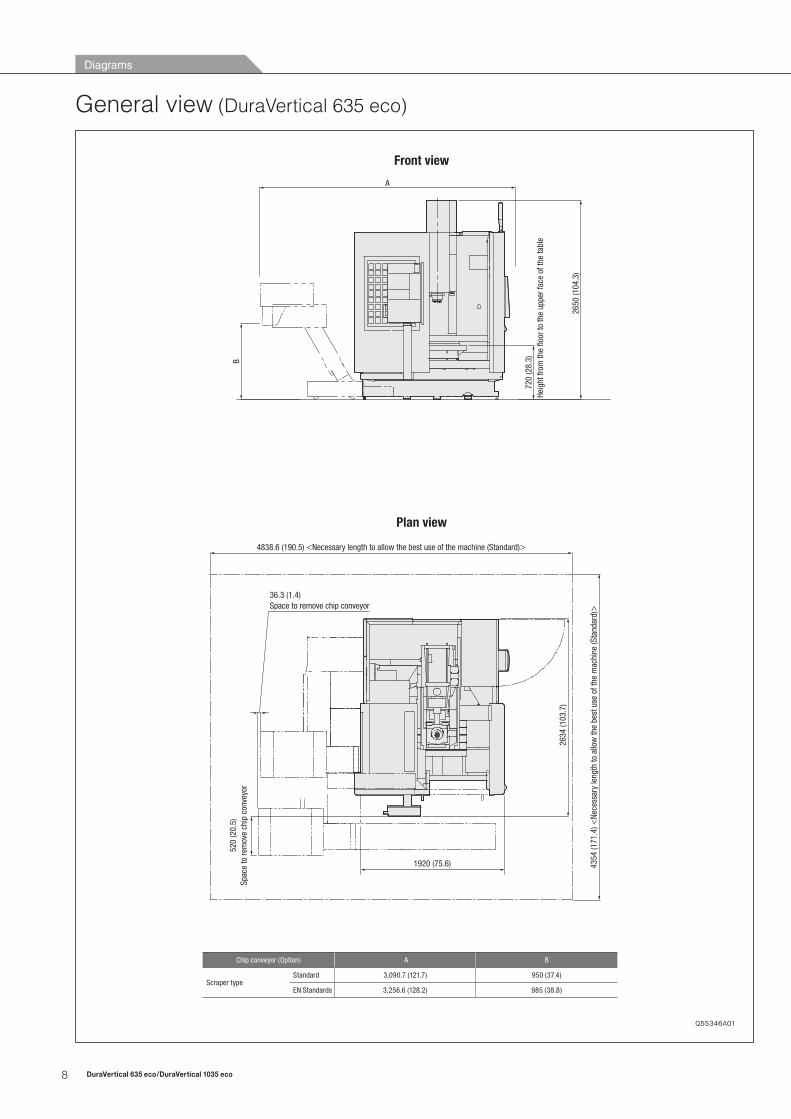
General view (DuraVertical 635 eco)
4838.6 (190.5) <Necessary length to allow the best use of the machine (Standard)>
4354
(171
.4) <
Nece
ssar
y le
ngth
to a
llow
the
best
use
of t
he m
achi
ne (S
tand
ard)>
2634
(103
.7)
2650
(104
.3)
1920 (75.6)
B
720
(28.
3)
A
Heig
ht fr
om th
e flo
or to
the
uppe
r fac
e of
the
tabl
e
520
(20.
5)Sp
ace
to re
mov
e ch
ip c
onve
yor
36.3 (1.4)Space to remove chip conveyor
Front view
Plan view
Q55346A01
Chip conveyor (Option) A B
Scraper typeStandard 3,090.7 (121.7) 950 (37.4)
EN Standards 3,256.6 (128.2) 985 (38.8)
9DuraVertical 635 eco/DuraVertical 1035 eco
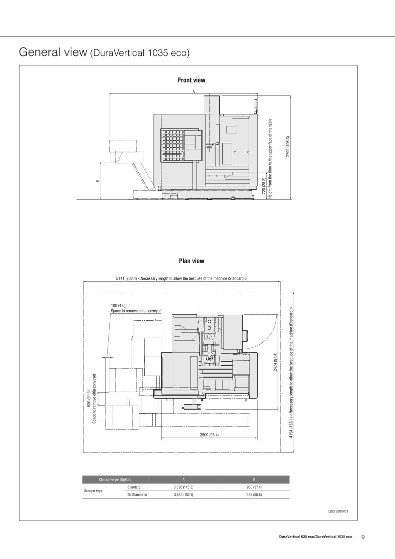
General view (DuraVertical 1035 eco)
2700
(106
.3)
720
(28.
3)
Heig
ht fr
om th
e flo
or to
the
uppe
r fac
e of
the
tabl
e
A
B
5141 (202.4) <Necessary length to allow the best use of the machine (Standard)>
4194
(165
.1) <
Nece
ssar
y le
ngth
to a
llow
the
best
use
of t
he m
achi
ne (S
tand
ard)>
2474
(97.
4)
520
(20.
5)Sp
ace
to re
mov
e ch
ip c
onve
yor
100 (4.0)Space to remove chip conveyor
2500 (98.4)
2700
(106
.3)
720
(28.
3)
Heig
ht fr
om th
e flo
or to
the
uppe
r fac
e of
the
tabl
e
AB
5141 (202.4) <Necessary length to allow the best use of the machine (Standard)>
4194
(165
.1) <
Nece
ssar
y le
ngth
to a
llow
the
best
use
of t
he m
achi
ne (S
tand
ard)>
2474
(97.
4)
520
(20.
5)Sp
ace
to re
mov
e ch
ip c
onve
yor
100 (4.0)Space to remove chip conveyor
2500 (98.4)
Front view
Plan view
Q55380A01
Chip conveyor (Option) A B
Scraper typeStandard 3,696 (145.5) 950 (37.4)
EN Standards 3,864 (152.1) 985 (38.8)

10 DuraVertical 635 eco/DuraVertical 1035 eco
Specifications
Numerical control unit specifications M730BM ● : Standard ○ : Option
Controlled axes
Controlled axes X, Y, Z ●
Simultaneously controlled axesPositioning/Linear interpolation/Circular interpolation(3/3/2)
●
Program input
Least input increment 0.001 mm (0.0001 in.) ●
Least command increment 0.001 mm (0.0001 in.) ●
Max. command value ±99,999.999 mm (±9,999.9999 in.) ●
Absolute/incremental programming G90/G91 ●
Decimal point inputDecimal point programming or electronic calculator type decimal point programming can be set using parameters.
●
Inch/Metric conversion G20/G21 ●
Interpolation
Positioning G00 ●
Helical interpolation ●
Thread cutting (designates lead/number of thread) ●
Feed
Cutting feedrate1–15,000 mm/min (0.01–590.6 ipm)When using high-precision control <look-ahead control>: 1–25,000 mm/min (0.01–984.3 ipm)
●
Pulse handle feedManual pulse generator: 1 unit×1, ×10, ×100 <per pulse>
●
Automatic acceleration/deceleration ●
Rapid traverse rate override F0/5/10/25/100% ●
Feedrate override 0–200% <10% increments> ●
Override cancel ●
Spindle orientation ●
Manual jog feed 0–5,000 mm/min (0–196.9 ipm) <20 steps> ●
Feed per minute ●
Feed per revolution ●
High-precision control (look-ahead control) ●
Program storage and editing
Part program storage length 1,280 m (4,200 ft) <500 KB> ●
Number of stored programs 1,000 programs ●
Program number/program name 4 digits ●
Undo/Redo function <MAPPS> ●
Line number display <MAPPS> ●
Operation and display
Operation panel: Display section 10.4-inch TFT color LCD ●
I/O Functions and units
I/O interfaceUSB ●
RS-232-C ○
50 MB Program storage area(for card DNC operation, for data backup) <MAPPS>
Files up to 10 MB in size can be edited ●
STM functions
Spindle speed function (S function) 5 digits S code ●
Spindle speed override 50–120% (10% increments) ●
Tool functions (T function) 4 digits T code ●
Miscellaneous function (M function) 3 digits M code ●
Tool offset
Tool length offset G43, G44, G49 ●
Cutter radius offset G40–G42 ●
Number of tool offsets 200 sets (diameter + length = 1 set) ●
Tool offset data memory D/H code, geometry/wear ●
Offset amount program input G10 ●
Coordinate system
Manual reference position return ●
Automatic reference position return G28 ●
2nd reference position return G30 ●
3rd, 4th reference position return ●
Reference position return check G27 ●
Return from reference position G29 ●
Automatic coordinate system setting ●
Coordinate system setting G92 ●
Workpiece coordinate system selection G54–G59 ●
Local coordinate system setting G52 ●
Machine coordinate system G53 ●
Additional workpiece coordinate systems 48 sets ●
Operation support functions
Single block ●
Optional stop ●
Optional block skip ●
Dry run ●
Machine lock ●
Auxiliary function lock ●
Mirror image M-code ●
Z-axis command cancel ●
Running time/Parts count display ●
Extended part program editing <MAPPS> ●
Background editing ●
Load meter display ●
Clock function CRT display ●
Programming support function
Optional chamfering/corner R ●
Hole machining canned cycle G80–G89 ●
Sub-program Up to 4 nestings ●
Custom macro ●
Exact stop check G09 ●
Exact stop check mode G61/G64 ●
Synchronous tapping ●
Automatic corner deceleration ●
Feed speed clamp by circular radius ●
Custom macro common variables <in total> 600 variables (#100–#199, #500–#999) ●
MORI-POST Advanced mode <MAPPS> ○
DXF import function <MAPPS> ○
Islands, open pockets <MAPPS> ○
Text engraving function <MAPPS> ○
Mechanical accuracy compensation
Backlash compensation ±9,999,999 pulses ●
Pitch error compensation ●
Single direction positioning ●
Rapid traverse/cutting feed backlash compensation ●
Machine control support function
Axis interlock ●
Automatic support function
Tool life management Number of tools managed: 200 tools ●
Safety and maintenance
Software overtravel ●
Self-diagnosisIncludes alarm display, I/O signal diagnosis and ladder diagram
●
Door interlock ●
Alarm history display ●
Operation history display ●● The information in this catalog is valid as of December 2011.

11DuraVertical 635 eco/DuraVertical 1035 eco
Machine specificationsItem DuraVertical 635 eco DuraVertical 1035 eco
Travel
X-axis travel mm (in.) 635 (25.0) 1,035 (40.7)
Y-axis travel mm (in.) 510 (20.1) 560 (22.0)
Z-axis travel mm (in.) 460 (18.1) 510 (20.1)
Distance from table surface to spindle gauge plane mm (in.) 120–580 (4.7–22.8) 120–630 (4.7–24.8)
TableTable working surface mm (in.) 790×560 (31.1×22.0) 1,200×560 (47.2×22.0)
Table loading capacity kg (lb.) 600 (1,320) 1,000 (2,200)
Spindle
Max. spindle speed min-1 12,000
Number of spindle speed ranges 2
Type of spindle taper hole No. 40
Spindle torque (40%ED) N·m (ft·lbf) 100 (73.8)
Feedrate
Rapid traverse rate mm/min (ipm) X/Y/Z: 30,500 (1,200.8)
Cutting feedrate mm/min (ipm) 15,000 (590.6) <25,000 (984.3) When using high-precision control <look-ahead control>>
Jog feedrate mm/min (ipm) 5,000 (196.9)
ATC
Type of tool shank CAT40 [BT40] [DIN40]
Type of retention knob DIN
Tool storage capacity 30
Max. tool diameterWith adjacent tools mm (in.) φ80 (φ3.1)
Without adjacent tools mm (in.) φ130 (φ5.1)
Max. tool length mm (in.) 300 (11.8)
Max. tool mass kg (lb.) 6 (13.2)
Tool changing timeTool-to-tool sec. 1.6
Cut-to-cut (Chip-to-chip) sec. 5.0
Motors Spindle drive motor (40%ED/cont) kW (HP) 11.5/8.5 (15.3/11.3)
Power sources (standard)
Electrical power supply (cont) kVA 28
Compressed air supply MPa (psi), L/min (gpm) 0.6 (87.0), 580 (153.1) <ANR>
Machine size
Machine height mm (in.) 2,650 (104.3) 2,700 (106.3)
Floor space (Width×Depth) mm (in.) 1,920 <without chip conveyor>×2,634 (75.6×103.7) 2,500 <without chip conveyor>×2,474 (98.4×97.4)
Mass of machine kg (lb.) 3,800 (8,360) <without chip conveyor> 4,250 (9,350) <without chip conveyor>
[ ] Option● Max. spindle speed: Depending on restrictions imposed by the workpiece clamping device, fixture and tool used, it may not be possible to rotate at the maximum spindle speed.● ANR: ANR refers to a standard atmospheric state; i.e., temperature at 20℃ (68°F); absolute pressure at 101.3 kPa (14.7 psi); and relative humidity at 65%.● Power sources, Machine size: The actual values may differ from those specified in the catalogue, depending on the optional features and peripheral equipment.● The information in this catalog is valid as of December 2011.
Standard & optional features ● : Standard ○ : Option
High-precision equipment
Direct scale feedback
X-axis ● ●
Y-axis ● ●
Z-axis ● ●
Others
Signal lamp 4 colors ● ●
DDRT interface ● ●
ATC
Type of tool shank
CAT40 ● ●
BT40 ○ ○
DIN40 ○ ○
Coolant
Coolant/air blast switching system ● ●
Coolant gun ● ●
Through-spindle coolant system <Separate type> <Center through> Interface <4.0 MPa (580 psi)> ● ●
Chip disposal
Chip conveyor Interface ● ●
DuraVertical 1035 eco
DuraVertical 635 eco
DuraVertical 1035 eco
DuraVertical 635 eco
● Some options are not available in particular regions. For details contact Mori Seiki.● The information in this catalog is valid as of December 2011.● Specifications, accessories, safety devices and functions are available upon request.
Do not use a flammable coolant or oil-based coolant because it may ignite and cause fire or machine breakage. If you have to use a flammable coolant for any reason, please consult with your sales representative.

EXPORTATION: All contracts are subject to export permit by the Government of Japan. Customer shall comply with the laws and regulations of the exporting country governing the exportation or re-exportation of the Equipment, including but not limited to the Export Administration Regulations. The Equipment is subject to export restrictions imposed by Japan and other exporting countries and the Customer will not export or permit the export of the Equipment anywhere outside the exporting country without proper government authorization. To prevent the illegal diversion of the Equipment to individuals or nations that threaten international security, it may include a “Relocation Machine Security Function” that automatically disables the Equipment if it is moved following installation. If the Equipment is so-disabled, it can only be re-enabled by contacting Mori Seiki or its distributor representative. Mori Seiki and its distributor representative may refuse to re-enable the Equipment if it determines that doing so would be an unauthorized export of technology or otherwise violates applicable export restrictions. Mori Seiki and its distributor representative shall have no obligation to re-enable such Equipment. Mori Seiki and its distributor representative shall have no liability (including for lost profits or business interruption or under the limited service warranty included herein) as a result of the Equipment being disabled.
<Precautions for Machine Relocation>
Nagoya Head Office □ 2-35-16 Meieki, Nakamura-ku, Nagoya City, Aichi 450-0002, Japan Phone: +81-52-587-1811
Tokyo Branch □ 18th floor, Shinagawa Intercity Tower A, 2-15-1 Konan Minato-ku, Tokyo 108-6018, Japan Phone: +81-3-5460-3570Nara Campus Nara No. 1 Plant □ 362 Idono-cho, Yamato-Koriyama City, Nara 639-1183, Japan Phone: +81-743-53-1121 Nara No. 2 Plant □ 106 Kita-Koriyama-cho, Yamato-Koriyama City, Nara 639-1160, Japan Phone: +81-743-53-1125Iga Campus □ 201 Midai, Iga City, Mie 519-1414, Japan Phone: +81-595-45-4151Chiba Campus □ 488-19 Suzumi-cho, Funabashi City, Chiba 274-0052, Japan Phone: +81-47-410-8800
● DCG, DDM, BMT and ORC are trademarks or registered trademarks of Mori Seiki Co., Ltd. in Japan, the USA and other countries.● If you have any questions regarding the content, contact your nearest Mori Seiki distributor or Technical Center.● The information in this catalog is valid as of December 2011. Designs and specifications are subject to changes without notice.● Mori Seiki is not responsible for differences between the information in the catalog and the actual machine.
DURAV6351035USA-ECO-EA04AV
V.1112.CDT.0000
Created in Japan
2-year warranty, twice the peace of mind. For machines delivered outside of Japan, parts relating to machine breakdown will be guaranteed free for 2 years from the date of installation, and labor costs to repair will be free for 1 year. Please contact your sales representative for details.