durable overlay systems with engineered cementitious composites (ecc)
DESCRIPTION
civil engineeringTRANSCRIPT
1
International Journal for Restoration of Buildingsand MonumentsVol. 9, No 2, 1–20 (2003)
Durable Overlay Systems with Engineered Cementitious Composites (ECC)
Victor C. Li The Advanced Civil Engineering Materials Research Laboratory (ACE-MRL)University of Michigan, USA
Abstract
This paper reviews recent research on the application of an engineered cementi-tious composite (ECC) as overlay in the repair of deteriorated concrete structures.ECC is an ultra-ductile fiber reinforced cement based composite, that hasmetal-like features when loaded in tension. The uniaxial tensile stress-strain curveshows a ‘yield’ point, followed by strain-hardening up to several percent strain,resulting in a material ductility of at least two orders of magnitude higher in com-parison to normal concrete or standard fiber reinforced concrete. ECC also hasunique cracking behavior. When loaded to beyond the elastic range, ECC main-tains crack width to below 100 µm, even when deformed to several percent tensilestrain. Experimental testing of ECC overlay reveals significant improvements in load car-rying capacity and in system ductility over conventional concrete or steel fiber rein-forced concrete overlays. The commonly observed overlay system failures bydelamination or by spalling are eliminated when ECC is applied. Numerical simu-lation of differential drying shrinkage also confirms the superior performance ofECC. In the presence of a vertical joint, large crack formation and/or delaminationare observed in mortar and fiber reinforced concrete overlays. These failure modesare suppressed when ECC is used as the overlay material. The unique material beha-vior of ECC makes it an ideal candidate material for durable overlay applications.Keywords: ECC, Repair Overlays, Ductility, Durability, Failure Mode.
Victor C. Li
2
Dauerhafte Beschichtungssysteme aus technisch entwickelten zementgebundenen zusammengesetzten Werkstoffen (ECC)
Zusammenfassung
In diesem Beitrag wird zunächst ein Überblick über neue Forschungsergebnissezur Anwendung eines technisch entwickelten zementgebundenen zusammengesetz-ten Werkstoffes (ECC) als Beschichtung im Rahmen von Instandsetzungsmaßnah-men beschädigter Stahlbetontragwerke gegeben. ECC ist ein extrem duktiler faser-bewehrter zementgebundener Werkstoff mit Eigenschaften unter Zugbelastung, diemit Metallen vergleichbar sind. Die Spannungs-Dehnungs-Linie dieser Werkstoffeweist eine „Fließgrenze“ auf und nach Erreichen dieser Grenzdehnung nimmt dieDehnung bis zu einigen Prozenten bei steigender Belastung zu (Dehnungserhär-tung). Die Duktilität dieser Werkstoffe ist mindestens zwei Größenordnungenhöher, als die von normalem Beton oder von konventionell faserbewehrten Beto-nen. ECC weist auch eine einzigartige Rissbildung auf. Wenn der Werkstoff überdie Elastizitätsgrenze hinaus belastet wird, bleibt die Rissweite unter 100 µm,selbst wenn die Verformung unter Zugspannung einige Prozent erreicht.
Ergebnisse von Versuchen mit ECC Reparaturschichten haben gezeigt, dass damiteine signifikante Verbesserung des Lasttragvermögens und der Duktilität erreichtwerden kann, im Vergleich zum Verhalten von Bauteilen, die mit konventionellemBeton oder mit Stahlfaserbeton beschichtet wurden. Das häufig beobachtete Versa-gen von Beschichtungssystemen durch Ablösen oder Abplatzen kann durch die Ver-wendung von ECC vermieden werden. Das weitaus günstigere Verhalten von ECCkann auch durch die numerische Simulation des differentiellen Trocknungsschwin-dens bestätigt werden. Über vertikalen Rissen werden in Beschichtungen aus Mör-tel oder faserbewehrtem Beton weit klaffende Risse und/oder Ablösen beobachtet.Diese Art des Versagens wird ausgeschlossen, wenn ECC zum Beschichten ver-wendet wird. ECC ist wegen seiner einzigartigen Werkstoffeigenschaften eineideale Alternative für dauerhafte Reparaturbeschichtungen.Stichwörter: ECC, Reparaturbeschichtung, Duktilität, Dauerhaftigkeit, Versagensmodus.

Durable Overlay Systems with Engineered Cementitious Composites (ECC)
3
1 IntroductionOverlay is a common method of repairing deteriorated infrastructures, includingpavements, bridge decks and parking garage decks. The overlay material may beasphalt, plain concrete, polymer concrete or fiber reinforced concrete. The con-crete substrate may or may not have its steel reinforcements exposed when theoverlay is placed. The durability of the overlay system is a matter of significant interest, since theirfailure by delamination, spalling or restrained shrinkage cracking and subsequentreinforcement corrosion leads to repeated maintenance needs and loss of use.Increasingly, the design life of an overlay is expected to last over twenty years. Theapplication of a very ductile fiber reinforced cementitious composite as the overlaymaterial may overcome the commonly observed overlay durability problems. Aseries of experimental, analytical and numerical investigations carried out over thelast several years point to a high potential of a much more durable repaired systemwhen engineered cementitious composites (ECC) are used in place of normal con-crete.
After a brief introduction to ECC, this paper first reviews research on the resistanceto delamination and spalling of ECC overlay system under both monotonic andfatigue loading. The influence of ECC/concrete interface roughness is examined. Anewly developed version of ECC, that can be sprayed to form the overlay (or forgeneral repair), is presented. Resistance to drying induced damage in such repairedsystems is also discussed.
2 Engineered Cementitious CompositesECC is a special class of high performance fiber reinforced concrete with extremetensile ductility, typically in the 3-5 % range (about 300-500 times that of normalconcrete and fiber reinforced concrete (FRC)) [1,2]. ECC attains high ductilitywith relatively low fiber content (typically less than 2-3 %) via microstructuralcontrol. Micromechanics provides guidelines on tailoring of the fiber, matrix andinterface properties. A typical tensile stress-strain curve is shown in Figure 1, foran ECC reinforced with 2.5 % PVA (REC 15) fibers. After first cracking, tensile load capacity continues to increase, resulting in a macro-scopic strain-hardening phenomenon accompanied by multiple microcracking. Thecrack width development is also shown in Figure 1. It is clear, that the crack widthincreases steadily up to about 60 µm, at about 1 % strain. Thereafter, the crack widthstabilizes and tends to remain constant at a steady state crack width even as the com-posite strain reaches 4 %.

Victor C. Li
4
The steady state crack width is governed by the fiber bridging property, and is rela-ted to the fiber modulus, diameter, and interface chemical and frictional bonds.Lower fiber content leads to larger crack width and vise versa. For example, wehave observed, that a 2 % volume fraction of the same composite produces a steadystate crack width of about 80 µm. Note that this steady state crack width is an intrin-sic material property. It is independent of the applied load, and size and geometryof the ECC overlay.
The small crack width at the material composite level described above has beenobserved in an increasingly large database of experiments of reinforced ECC (orR/ECC) at the structural element scale, (see e.g. [3,4]).
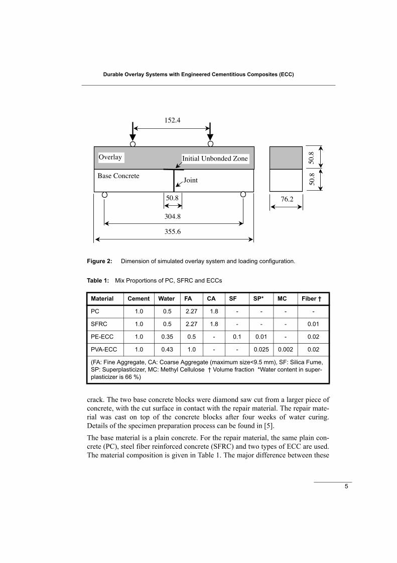
3 Overlay Specimen Configuration and MaterialsIn order to simulate the most adverse loading situation on an overlay, Lim and Li[5] proposed the specimen and loading configuration shown in Figure 2. The baseconcrete has a joint, above which a 50.8 mm delaminated interface (labeled as‘initial unbonded zone’) is artificially introduced, simulating the presence of adefect at the interface between the repair material and the base concrete. The fourpoint bending setup creates a mixed mode loading condition for this interfacial
Figure 1: A typical stress-strain curve of ECC, showing high tensile strain capacity, andtight crack width control.
0 1 2 3 40
1
2
3
4
5
6
Crack W
idth (µm)
S t r e s s
Stre
ss (M
Pa)
0
2 0
4 0
6 0
8 0
1 0 0 Crack w idth
Strain (%)
Durable Overlay Systems with Engineered Cementitious Composites (ECC)
5
crack. The two base concrete blocks were diamond saw cut from a larger piece ofconcrete, with the cut surface in contact with the repair material. The repair mate-rial was cast on top of the concrete blocks after four weeks of water curing.Details of the specimen preparation process can be found in [5].The base material is a plain concrete. For the repair material, the same plain con-crete (PC), steel fiber reinforced concrete (SFRC) and two types of ECC are used.The material composition is given in Table 1. The major difference between these
Figure 2: Dimension of simulated overlay system and loading configuration.
Table 1: Mix Proportions of PC, SFRC and ECCs
Material Cement Water FA CA SF SP* MC Fiber †
PC 1.0 0.5 2.27 1.8 - - - -
SFRC 1.0 0.5 2.27 1.8 - - - 0.01
PE-ECC 1.0 0.35 0.5 - 0.1 0.01 - 0.02
PVA-ECC 1.0 0.43 1.0 - - 0.025 0.002 0.02
(FA: Fine Aggregate, CA: Coarse Aggregate (maximum size<9.5 mm), SF: Silica Fume, SP: Superplasticizer, MC: Methyl Cellulose † Volume fraction *Water content in super-plasticizer is 66 %)
Overlay
Base Concrete
152.4
50.8
304.8
355.6
76.2
50.8
50.8
Joint
Initial Unbonded Zone

Victor C. Li
6
four materials is their tensile behavior, shown in Figure 3. The PC is brittle. TheSFRC is quasi-brittle, meaning that a bridged crack will continue to open withdecreasing load-carrying capacity. The PE-ECC was designed with high moduluspolyethylene fiber, while the PVA-ECC was designed with a Poly-vinyl Alcoholfiber especially developed for ECC reinforcement [6]. Clearly, the ECC materialshave tensile strain capacity about two orders of magnitude higher than the PC orSFRC (about 0.01 %).
4 Resistance to Delamination and SpallingFigure 4 shows the failure behavior of the three overlay systems PC/PC, SFRC/PCand PE-ECC/PC. The corresponding load-deflection curves are shown in Figure 5.In the case of PC/PC, the interfacial defect propagated a small amount along theinterface, but kinked and immediately formed a spall going through the thicknessof the PC overlay. In the case of SFRC/PC, the kinked crack was bridged by thesteel fiber, allowing load, albeit decreasing, to be transmitted across this crack.This too formed a spall cutting through the full thickness of the overlay. In thecase of the system repaired with the PE-ECC material, the failure pattern is muchmore complex. It appeared that the initial horizontal defect propagated slightly
Figure 3: Tensile stress-strain curves of PC, SFRC, PVA-ECC and PE-ECC.
SFRC
PC
PVA-ECC
PE-ECC

Durable Overlay Systems with Engineered Cementitious Composites (ECC)
7
along the interface, then kinked, but was immediately trapped inside the ECCrepair material. Trapping means, that the kinked crack was arrested, so that addi-tional load was needed to drive the interface crack to propagate again along theinterface of the bi-material system. Then the kink-trap phenomenon repeated itselfa number of times, resulting in a pattern of kinked-trapped cracks. This processfinally stopped, when the mid-section of the overlay acts like a beam, and the fle-xural strength of the ECC beam was exceeded. The final failure occurred, when aflexural fracture formed close to the top of the joint. Unlike the PC/PC andSFRC/PC overlay systems, the final failure of the ECC/PC system had nothing to
Figure 4: Failure modes of (a) PC/PC, (b) SFRC/PC and (c) PE-ECC/PC overlay sys-tems.
Joint
(a)
Joint
(b)
Joint
(c)

Victor C. Li
8
do with the position of the interfacial crack-tip at failure. A close-up of the multi-ple kink-trap phenomenon is shown in Figure 6.As indicated in Figure 5, the peak load and the deflection magnitude at peak loadare both higher for the ECC overlay system, compared to the PC and SFRC overlaysystems. This suggests, that by eliminating the delamination and spall processes,the ECC overlay provides both higher load carrying capacity and energy absorptioncapacity to the repaired system. It is interesting to note, that the “structural” strengthof the ECC overlay system is more than double that of the PC overlay system,despite the fact, that the ECC and the PC both had about the same cracking strength(approximately 4 MPa, Figure 3). By trapping the microcracks inside the overlay, itmay be expected, that water penetration from the top surface will be minimized inthe ECC overlay, leading to improved durability of the ECC overlay system.
The kink-trap phenomenon occurs only when ECC is used as the overlay. A fracturemechanics theory based on the energetics of crack propagation along the interfaceand crack kinking into the repair material, as well as the fracture resistance in thesetwo crack paths, was proposed to explain the kink-trap phenomenon. The rapidly
Figure 5: Load-deflection curves of the PC/PC, SFRC/PC and the PE-ECC/PC overlaysystems.
0
4
8
12
16
0 1 2 3 4 5 6 7 8
Load (
kN
)
Deflection (mm)
Conc./Conc.
Conc./SFRC
Conc./ECC
PC/PC
SFRC/PC
PE-ECC/PC
Deflection (mm)
L
oad
(kN
)

Durable Overlay Systems with Engineered Cementitious Composites (ECC)
9
rising toughness of ECC as the kink crack grows in length is considered important.More details can be found in [5]. Numerical modeling by Kabele [7] successfullyreproduced this kink-trap phenomenon.
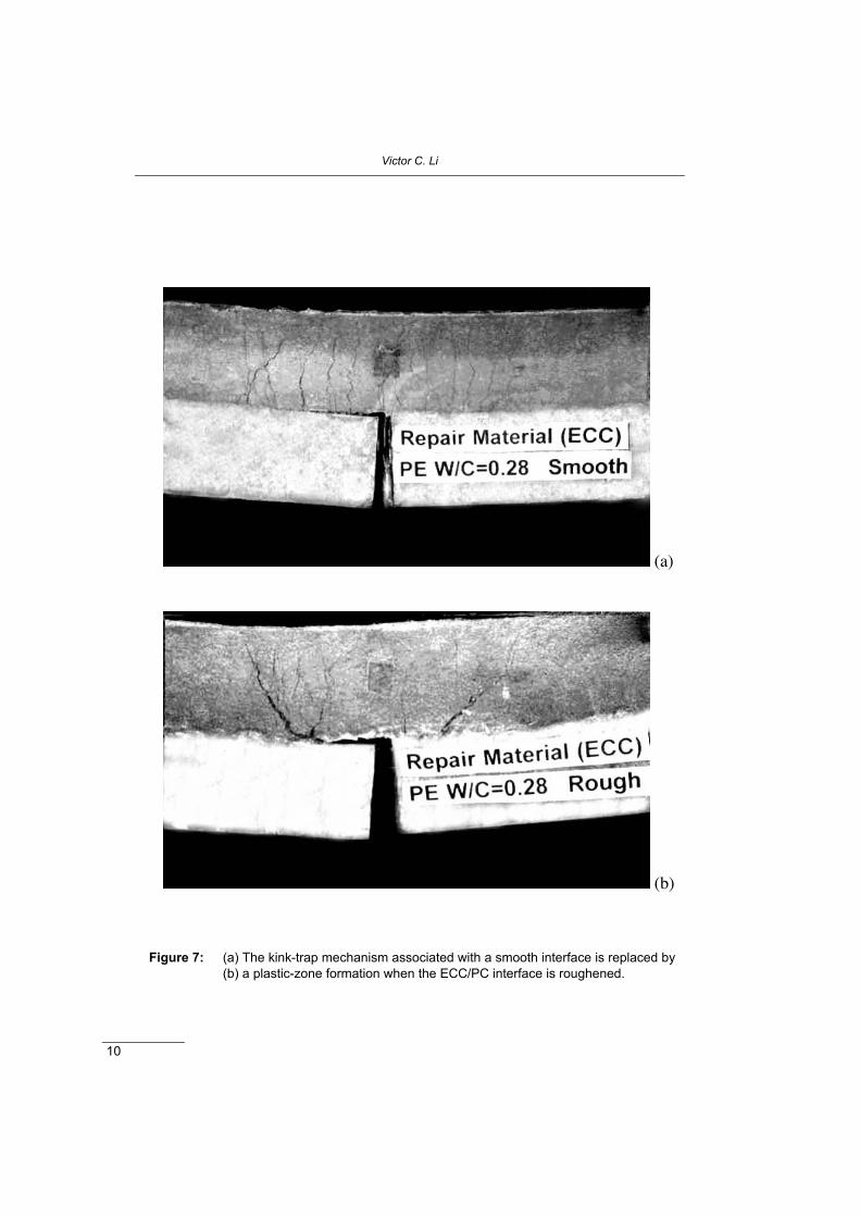
5 Influence of Surface PreparationThe interface fracture toughness of a bi-material system is known to depend on theroughness of the interface. This in turn could influence the kink-trap phenomenon.The influence of interface roughness on the kink-trap phenomenon was examinedby Kamada and Li [8]. In their study, some specimens were prepared with the topof the base concrete roughened by a scarifier, prior to the casting of the ECC over-lay. The PE-ECCs employed in this study have compositions slightly different thanthat listed in Table 1, but these differences (mainly in the fiber content and the w/cratio) are not expected to change the conclusions. The failure pattern is indeed affected by the smoothness of the interface. Figure 7shows the contrast. When the interface is rough, the kinked crack cannot return tothe interface. Instead, it developed into a fan-like “plastic zone” with many micro-crack branches inside. Increasing load is needed in order to develop this “plasticzone”. In fact, the load deformation curves between the two sets of test are difficultto distinguish, given the variability from specimen to specimen. (Additional tests by
Figure 6: Close-up view of the kink-trap mechanism in the PE-ECC/PC overlay system.
Victor C. Li
10
Figure 7: (a) The kink-trap mechanism associated with a smooth interface is replaced by(b) a plastic-zone formation when the ECC/PC interface is roughened.
(a)
(b)

Durable Overlay Systems with Engineered Cementitious Composites (ECC)
11
Zhang and Li [9] do show, that the deformability of the smooth interface overlaysystem is higher than that of the rough interface overlay system). In both cases,however, the peak load and the corresponding load-point displacement reached aremuch higher than those when PC or SFRC are used as the overlay material. Thuswhile the kink-crack mechanism prevalent in the smooth interface case gives wayto the “plastic zone” formation, the macroscopic behavior remains similar. Thebenefits of using ECC over PC or regular FRC seem to be independent of interfaceroughness or surface preparation.
6 Durability Under Fatigue LoadingBecause overlay systems are often subjected to repeated loading, the fatigue dura-bility performance is of interest. The fatigue performance of ECC overlay systemwas examined by Zhang and Li [9], using the same test set-up as described abovefor monotonic loading. The PVA-ECC material with composition detailed in Table1 was used as the repair material. The control test was carried out with a PC over-lay. Figure 8 summarizes the fatigue test data obtained, in the standard S-N curve for-mat. The equivalent flexural stress σ plotted on the vertical axis has been calculatedfrom the applied moment M:
(1)
where B and h are the width and depth of the overlay. It appears that there is littledifference in the fatigue performance whether the interface is smooth or rough. Inboth cases, the fatigue life for the ECC overlay system is significantly higher thanthat of the PC overlay system.
In terms of crack pattern, there is no observable difference between tests carried outunder monotonic and fatigue loading.
7 Repairing with Sprayed ECC
A special version of ECC was developed recently for spray repair operation [10].For this processing route, the fresh mix must be deformable enough during themixing and pumping process, but must stiffen up rapidly after the sprayed ECCreaches the concrete substrate. This was attained by controlling the rheology of thecement paste through optimal combinations of a superplasticizer, a viscosity agent,and the addition of calcium aluminate cement particles. The strategy of using the
2
61 Bh
M=σ

Victor C. Li
12
rheology of the paste to drive the flow of the ECC while keeping other ingredientssimilar to that shown for PVA-ECC in Table 1 makes it possible to satisfy the freshproperty requirement for spraying, while adhering to the micromechanics criteriafor tensile strain-hardening. A test set up similar to that shown in Figure 1 was used. The specimen was fabrica-ted by spraying ECC onto a panel and then saw cut to the required testing dimensi-ons as shown in Figure 9. Control tests were carried out with standard pre-packagedmortar mixes commercially designed for repair jobs. The test specimens were iden-tical to those shown in Figure 1 except that the layer thicknesses were reduced by50 %. The test result (Figure 10) shows, that the specimen using the sprayed ECCis more than 100 % stronger and several times more ductile than those repaired withstandard repair mortar mixes.
8 Resistance to Drying Induced DamageAfter an overlay is placed, drying shrinkage of the overlay may result in cracks asthe overlay is restrained from deforming by the substrate concrete. The restrainedshrinkage cracks could increase the flow of water and aggressive agents into the
Figure 8: S-N curves of PVA-ECC/PC and PC/PC overlay systems tested under flexuralfatigue loading.
0.00 1.00 2.00 3.00 4.00 5.00 6.00Log(N)
0.00
2.00
4.00
6.00
8.00
10.00
12.00
14.00
16.00
18.00
Max
imum
Fle
xura
l Stre
ss (M
Pa)
ECC, Rough
ECC, Smooth
PC, Smooth
Linear fits

Durable Overlay Systems with Engineered Cementitious Composites (ECC)
13
Figure 9: Spray PVA-ECC/PC overlay specimen.
Figure 10: Load-deflection curves of sprayed PVA-ECC/PC overlay systems, showingmuch higher peak load and deformation capacity in comparison to spray pre-packaged mortars commonly used in concrete structure repair.
51 mm
Sprayed ECC
Concrete substrate
concrete ECC
0
0.5
1
1.5
2
2.5
0 1 2 3 4 5 6 7
Load
(kN
)
Deflection (mm)
Pre-packaged mortars/PC
PVA-ECC/PC
Deflection (mm)
Load
(kN
)
Victor C. Li
14
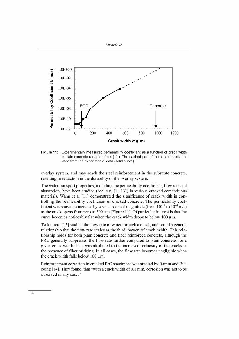
overlay system, and may reach the steel reinforcement in the substrate concrete,resulting in reduction in the durability of the overlay system.The water transport properties, including the permeability coefficient, flow rate andabsorption, have been studied (see, e.g. [11-13]) in various cracked cementitiousmaterials. Wang et al [11] demonstrated the significance of crack width in con-trolling the permeability coefficient of cracked concrete. The permeability coef-ficient was shown to increase by seven orders of magnitude (from 10-11 to 10-4 m/s)as the crack opens from zero to 500 µm (Figure 11). Of particular interest is that thecurve becomes noticeably flat when the crack width drops to below 100 µm.
Tsukamoto [12] studied the flow rate of water through a crack, and found a generalrelationship that the flow rate scales as the third power of crack width. This rela-tionship holds for both plain concrete and fiber reinforced concrete, although theFRC generally suppresses the flow rate further compared to plain concrete, for agiven crack width. This was attributed to the increased tortuosity of the cracks inthe presence of fiber bridging. In all cases, the flow rate becomes negligible whenthe crack width falls below 100 µm.
Reinforcement corrosion in cracked R/C specimens was studied by Ramm and Bis-coing [14]. They found, that “with a crack width of 0.1 mm, corrosion was not to beobserved in any case.”
Figure 11: Experimentally measured permeability coefficient as a function of crack widthin plain concrete (adapted from [11]). The dashed part of the curve is extrapo-lated from the experimental data (solid curve).
1.0E-12
1.0E-10
1.0E-08
1.0E-06
1.0E-02
1.0E+00
0 200 400 600 800 1000 1200
Crack width w (µm)
Perm
eabi
lity
Coe
ffici
ent k
(m/s
)
ECC Concrete
1.0E-04

Durable Overlay Systems with Engineered Cementitious Composites (ECC)
15
These experimental data suggest, that the 100 µm crack width define a thresholdabove which significant increase in transport properties is observed. An effectivemeans of minimizing the transport of harmful ingredients via water movementthrough cracks is to control crack width to below 100 µm.
Restrained shrinkage tests were carried out with ECC and standard concrete usingthe technique introduced by Grzybowski and Shah [15]. Cementitious materialswere cast around a steel ring and the development of the crack width as a functionof time was monitored. Figure 12 shows, that the crack width of the ECC materialis less than 80 µm, more than an order of magnitude lower than that for normal con-crete (about 1 mm) for the specimen dimensions used. These test results suggest,that while ECC has higher shrinkage due to the higher cement content, the shrin-kage deformation is accommodated by a larger number of cracks each with a muchsmaller crack width in comparison to normal concrete.
Figure 12: Crack width development for PVA-ECC and normal concrete in restrained dry-ing shrinkage test.
0.0
0.2
0.4
0.6
0.8
1.0
1.2
1.4
1.6
0 20 40 60 80 Drying Time t (days)
Cra
ck W
idth
w (m
m)
Concrete ECCFit Fit
0.0
0.2
0.4
0.6
0.8
1.0
1.2
1.4
1.6
0 20 40 60 80 Drying Time t (days)
Cra
ck W
idth
w (m
m)
Concrete ECCFit Fit
Victor C. Li
16
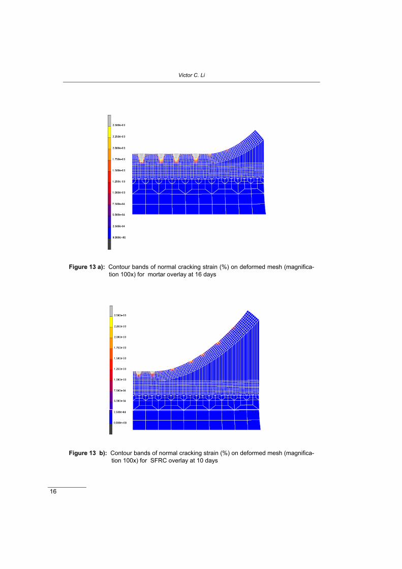
Figure 13 a): Contour bands of normal cracking strain (%) on deformed mesh (magnifica-tion 100x) for mortar overlay at 16 days
Figure 13 b): Contour bands of normal cracking strain (%) on deformed mesh (magnifica-tion 100x) for SFRC overlay at 10 days

Durable Overlay Systems with Engineered Cementitious Composites (ECC)
17
These shrinkage crack width are also shown in Figure 11, which once again suggestthat after cracking, the rate of water transport through the ECC overlay (at 3x10-11
m/s) can be many orders of magnitude lower than that in normal concrete (at 8x10⁻¹
m/s). The transport rate does not depend on the number of cracks, but dependsnon-linearly on the crack width.
Differential drying through the thickness of an overlay may lead to cracking of theoverlay and delamination at the interface starting at a through thickness verticaljoint. This problem for mortar overlay has been carefully analyzed numerically byMartinola and Wittmann [15]. The same problem was analyzed by Kabele [7] con-trasting the failure behavior of mortar, SFRC and ECC overlays. The numericalresults are shown in Figure 13. In all cases, vertical cracking begins at the top sur-face of the overlays. In the case of mortar overlay, through thickness cracks in theoverlay relieve the tensile stress, limiting the delamination to near the joint. In thecase of the SFRC overlay, delamination is severe since the horizontal stress inducedby the differential drying cannot be relieved in this manner, as the cracks are brid-ged by the steel fibers. In the case of the ECC overlay, neither large cracks nordelamination occurs even after a long term drying. The horizontal stress is relievedby the large inelastic tensile strain capacity of the ECC. In addition, eventual inter-face crack propagation is inhibited by the kink-trapping mechanism described ear-lier.
Figure 13 c): Contour bands of normal cracking strain (%) on deformed mesh (magnifica-tion 100x) for ECC overlay at 100 days (adapted from [7]).
Victor C. Li
18
9 ConclusionsSevere mechanical loading in the presence of a joint in the concrete substrate and adefect on the horizontal interface between the concrete substrate and the repairmaterial shows, that ECC overlay systems outperform SFRC or PC overlaysystems. Delamination and spalling are both prevented by either development ofthe kink-crack trapping mechanism, or the formation of a large plastic zone in theECC layer. The kink-crack trapping mechanism prevails when the ECC/PC inter-face is smooth, while the plastic zone mechanism prevails when the ECC/PC inter-face is rough. In either case, the macroscopic system behavior in terms ofload-deflection response is similar, and shows much higher peak load and cor-responding deflection value at failure. These observations appear to hold for bothmonotonic and fatigue loading. Fatigue tests reveal significantly improved fatiguelife at any stress level in the ECC/PC overlay system in comparison to PC/PCoverlay system.Despite the higher amount of cement in ECC in comparison to normal concrete, anda higher free shrinkage, restrained shrinkage cracks in ECC are at least an order ofmagnitude lower than normal concrete, suggesting improved durability against theingress of water and aggressive agents migrating into the repair layer. Numericalsimulation of differential drying also suggests, that ECC/PC overlay outperformother overlay systems in preventing large crack formation in the overlay anddelamination from the edge of a through-thickness joint.
From both the mechanical loading and the environmental loading point of view,there is substantial evidence, that ECC can serve as a durable overlay material. Theunique tensile strain-hardening behavior and the tight crack width control of ECCare responsible for the ECC overlay system performance described in this paper.ECC can be applied by the regular casting technique, or by means of spraying, aprocess similar to that of shotcreting.
Acknowledgements
Part of this research has been supported by a grant from the National ScienceFoundation to the ACE-MRL at the University of Michigan. Supply of PVA fiberby Kuraray Co. Ltd., and permission to reproduce Figure 13 by Dr. Petr Kabele(Czech Technical University at Prague) are gratefully acknowledged.

Durable Overlay Systems with Engineered Cementitious Composites (ECC)
19
References
1. V.C. Li, Engineered Cementitious Composites – Tailored CompositesThrough Micromechanical Modeling, in Fiber Reinforced Concrete: Presentand the Future, edited by N. Banthia, A. Bentur, A.? and A. Mufti, CanadianSociety for Civil Engineering, Montreal, 64-97 (1998)
2. V.C. Li, S. Wang and C. Wu, Tensile Strain-Hardening Behavior ofPVA-ECC, ACI J. of Materials, 98, 6, 483-492 (2001)
3. Fischer, G., and V.C. Li, “Effect Of Matrix Ductility On Deformation Beha-vior of Steel Reinforced ECC Flexural Members Under Reversed CyclicLoading Conditions,” ACI J. of Structures, 99, 6, 781-790 (2002)
4. T. Kanda, S. Watanabe and V.C. Li, Application of Pseudo Strain HardeningCementitious Composites to Shear Resistant Structural Element, in FractureMechanics of Concrete Structures, Proceedings FRAMCOS-3, AEDIFICA-TIO Publishers, Freiburg, Germany, 1477-1490 (1998)
5. Y.M. Lim, and V.C. Li, Durable Repair of Aged Infrastructures Using Trap-ping Mechanism of Engineered Cementitious Composites J. Cement andConcrete Composites, 19, 4, 373-385 (1997)
6. V.C. Li, C. Wu, S. Wang, A. Ogawa, and T. Saito, “Interface Tailoring forStrain-Hardening PVA-ECC,” ACI J. of Materials 99, 5, 463-472 (2002)
7. P. Kabele, Assessment of Structural Performance of Engineered Cementi-tious Composites by Computer Simulation. CTU Report 4, V.5, Czech Tech-nical University, Prague (2001)
8. T. Kamada and V.C. Li, The Effects of Surface Preparation on the FractureBehavior of ECC/Concrete Repair System, J. of Cement and Concrete Com-posites, 22, 6, 423-431 (2000)
9. J. Zhang, and V.C. Li, Monotonic and Fatigue Performance in Bending ofFiber Reinforced Engineered Cementitious Composite in Overlay System,J. of Cement and Concrete Research, 32, 3, 415-423 (2002)
10. Kim, Y.Y., H.J. Kong and V.C. Li, “Design of a Sprayable EngineeredCementitious Composite (ECC)”, Submitted, ACI J. of Materials (2002)
11. K. Wang, D.J. Jansen, and P. Shah, Permeability study of cracked concrete,Cement and Concrete Research, 27, 3, 381-393 (1997)
12. M. Tsukamoto, Tightness of Fiber Concrete, Darmstadt Concrete, 5,215-225 (1990)
13. J.S. Lawler, D. Zampini, and S.P. Shah, Permeability of Cracked HybridFiber-Reinforced Mortar Under Load, ACI Materials J., 99, 4, 379-385(2002)

Victor C. Li
20
14. W. Ramm and M. Biscoping, Autogenous healing and reinforcement corro-sion of water-penetrated separation cracks in reinforced concrete. NuclearEngineering and Design 179, 191-200 (1998)
15. M. Grzybowski, and S.P. Shah, Shrinkage Cracking of Fiber ReinforcedConcrete, ACI Materials J., 87, 138-148 (1990)
16. G. Martinola and F.H. Wittmann, Application of Fracture mechanics toOptimize Repair Mortar Systems, in Fracture Mechanics of Concrete Struc-tures, Proceedings of FRAMCOS-2 (F.H. Wittmann ed.) AEDIFICATIOPublishers, Freiburg, Germany, 1481-1492 (1995)
Victor Li is a professor of civil and environmentalengineering at the University of Michigan, USA. He isthe director of the Advanced Civil Engineering Mate-rials Research Laboratory, a Fellow of the AmericanSociety of Civil Engineers, and a Fellow of the Ameri-can Society of Mechanical Engineers. Professor Li’sresearch interests include micromechanics-baseddesign of fiber reinforced cementitious composites,repair and retrofit of infrastructures, and smart designand sustainability of infrastructure systems.