dupont delrin acetal resin molding guide - distrupol · 1 general information description delrin®...
TRANSCRIPT

TECHNICAL INFORMATION
DuPont™ Delrin® acetal resinMolding Guide

ii
iii
Table of Contents
PagesGeneral Information . . . . . . . . . . . . . . . . . . . . . . . . . . . . . . . . . . 1
Description . . . . . . . . . . . . . . . . . . . . . . . . . . . . . . . . . . . . . . 1Compositions . . . . . . . . . . . . . . . . . . . . . . . . . . . . . . . . . . . . 1SafetyPrecautionstoObserve
WhenMoldingDelrin®AcetalResins . . . . . . . . . . . . . . . 2Packaging . . . . . . . . . . . . . . . . . . . . . . . . . . . . . . . . . . . . . . . 3Polymer Structure and Processing Behavior . . . . . . . . . . . . . . 4
GlassTransitionandMelting . . . . . . . . . . . . . . . . . . . . . . . . 4PVTDiagrams . . . . . . . . . . . . . . . . . . . . . . . . . . . . . . . . . . . . 4Heating-CoolingBehavior . . . . . . . . . . . . . . . . . . . . . . . . . . . 6ViscosityandRheologicalBehavior . . . . . . . . . . . . . . . . . . . . 6Injection Molding Unit . . . . . . . . . . . . . . . . . . . . . . . . . . . . . . . . 8
ScrewDesign . . . . . . . . . . . . . . . . . . . . . . . . . . . . . . . . . . . . 9ELCeeScrewforOptimumProductivity . . . . . . . . . . . . . . . 10CylinderTemperatureControl . . . . . . . . . . . . . . . . . . . . . . . 10CylinderAdaptor . . . . . . . . . . . . . . . . . . . . . . . . . . . . . . . . . 10Non-ReturnValve(BackFlowValve—BFV) . . . . . . . . . . . . . 10Nozzle . . . . . . . . . . . . . . . . . . . . . . . . . . . . . . . . . . . . . . . . . .11EvaluationofMeltQuality . . . . . . . . . . . . . . . . . . . . . . . . . . .11Molds . . . . . . . . . . . . . . . . . . . . . . . . . . . . . . . . . . . . . . . . . . . . . 13
AbilitytoFill . . . . . . . . . . . . . . . . . . . . . . . . . . . . . . . . . . . . 13Gates . . . . . . . . . . . . . . . . . . . . . . . . . . . . . . . . . . . . . . . . . . 14RunnerSystem . . . . . . . . . . . . . . . . . . . . . . . . . . . . . . . . . . 16NozzleandSprue . . . . . . . . . . . . . . . . . . . . . . . . . . . . . . . . 17HotRunnerMoldforCrystallinePolymers . . . . . . . . . . . . . 18Vents . . . . . . . . . . . . . . . . . . . . . . . . . . . . . . . . . . . . . . . . . . 19Undercuts . . . . . . . . . . . . . . . . . . . . . . . . . . . . . . . . . . . . . . 20SharpCorners . . . . . . . . . . . . . . . . . . . . . . . . . . . . . . . . . . . 21RibsDesign . . . . . . . . . . . . . . . . . . . . . . . . . . . . . . . . . . . . . 21WeldLines . . . . . . . . . . . . . . . . . . . . . . . . . . . . . . . . . . . . . 21MoldMaintenance . . . . . . . . . . . . . . . . . . . . . . . . . . . . . . . 22MoldCleaning . . . . . . . . . . . . . . . . . . . . . . . . . . . . . . . . . . . 22
(continued)

iv
Table of Contents (continued)
PagesMolding Process . . . . . . . . . . . . . . . . . . . . . . . . . . . . . . . . . . . . . 23
Start-upandShutdownProcedures . . . . . . . . . . . . . . . . . . 23OperatingConditionsforDelrin®
—TemperatureSettings . . . . . . . . . . . . . . . . . . . . . . . . . 24OperatingConditionsforDelrin®
—MoldingCycle . . . . . . . . . . . . . . . . . . . . . . . . . . . . . . 26OptimumProductivityMolding . . . . . . . . . . . . . . . . . . . . . . 29StandardMoldingConditions
forISOTensileBars . . . . . . . . . . . . . . . . . . . . . . . . . . . . 30HoldPressureTime
viaIn-cavityPressureMeasurement . . . . . . . . . . . . . . . 30Dimensional Considerations . . . . . . . . . . . . . . . . . . . . . . . . . . . 31
FundamentalsofDimensionalControl . . . . . . . . . . . . . . . . . . . . . . . . . . . . . . . . . . . . . . 31
MoldShrinkage . . . . . . . . . . . . . . . . . . . . . . . . . . . . . . . . . . 31FactorsAffectingMoldShrinkage . . . . . . . . . . . . . . . . . . . . 31MoldShrinkageofFilledResins . . . . . . . . . . . . . . . . . . . . . 31EffectofPigments . . . . . . . . . . . . . . . . . . . . . . . . . . . . . . . 33Post-MoldingShrinkage . . . . . . . . . . . . . . . . . . . . . . . . . . . 34InsertMolding . . . . . . . . . . . . . . . . . . . . . . . . . . . . . . . . . . . 35Annealing . . . . . . . . . . . . . . . . . . . . . . . . . . . . . . . . . . . . . . 35EnvironmentalChanges . . . . . . . . . . . . . . . . . . . . . . . . . . . 35DimensionalTolerances . . . . . . . . . . . . . . . . . . . . . . . . . . . . 36Auxiliary Operations . . . . . . . . . . . . . . . . . . . . . . . . . . . . . . . . . 37
MaterialHandling . . . . . . . . . . . . . . . . . . . . . . . . . . . . . . . . 37RegroundResin . . . . . . . . . . . . . . . . . . . . . . . . . . . . . . . . . 37Drying . . . . . . . . . . . . . . . . . . . . . . . . . . . . . . . . . . . . . . . . . 37Coloring . . . . . . . . . . . . . . . . . . . . . . . . . . . . . . . . . . . . . . . . 38Disposal . . . . . . . . . . . . . . . . . . . . . . . . . . . . . . . . . . . . . . . 38Troubleshooting Guide . . . . . . . . . . . . . . . . . . . . . . . . . . . . . . . 39
Index . . . . . . . . . . . . . . . . . . . . . . . . . . . . . . . . . . . . . . . . . . . . . .42

1
General Information
DescriptionDelrin®acetalresinsaresemi-crystalline,thermoplasticpolymersmadebythepolymerizationofformaldehyde,andarealsocommonlyreferredtoaspolyoxymethylene(POM) .Theyhavegainedwidespreadrecognitionforreliabilityinmanythousandsofengineeringcomponentsallovertheworld .Sincecommercialintroductionin1960,Delrin®hasbeenusedintheautomotive,appliance,construction,hardware,electronics,andconsumergoodsindustries,amongothers .
Delrin®isnotedfor:
• Highmechanicalstrengthandrigidity
• Excellentdimensionalstability
• Naturallubricity
• Fatigueendurance
• Highresistancetorepeatedimpacts
• Excellentresistancetomoisture,gasolines,solventsandmanyotherneutralchemicals
• Toughnessatlowtemperature(downto–50°C[–58°F])
• Wideusefultemperaturerange(inair:–50to90°C[–58to194°F],withintermittentuseupto120°C[248°F]) .
• Goodelectricalinsulatingcharacteristics
• Easeoffabrication
Delrin®acetalresinsareavailableinavarietyofcompositionstomeetdifferentend-useandprocessingrequirements .
CompositionsThemainavailableDelrin®compositionscanbeclassifiedasfollows:
a . Standard
b . Toughened
c . Lowwear/Lowfriction
d . Glassfilled/Reinforced
e . UV-stabilized
Thestandardcompositionscoverabroadrangeofmeltviscosities .Thehighestviscositycomposition,solikeDelrin®100P,areoftenmoldedwhenmaximumtoughnesspropertiesareneeded .TheintermediatemeltviscosityDelrin®500Pisusedforgeneral-purposeinjectionapplications .Theresinshavinglowermeltviscosity,Delrin®900Pisusuallychosenforinjectionmoldingapplicationswithhard-to-fillmolds .
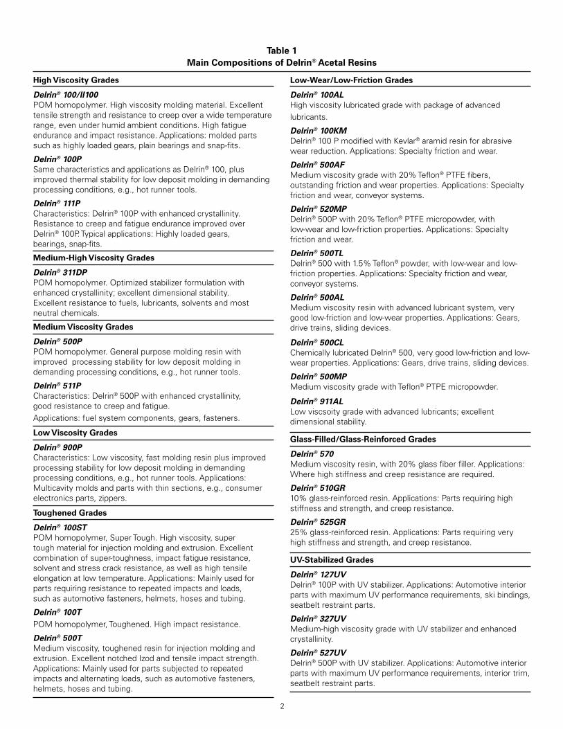
AsummaryofthemaincompositionsisshowninTable 1 .
Safety Precautions to Observe When Molding Delrin® Acetal ResinsDelrin®aswellasmanyotherthermoplasticpolymersdecomposestogaseousproductswhenheatedforaprolongedtime .Thesegasescangeneratehighpressuresifconfined .Ifmaterialisnotfreetoexitfromaninjectioncylinderthroughthenozzle,itmayblowbackthroughthehopper .
InthecaseofDelrin®acetalresin,decompositionisalmostentirelytogaseousproducts,sopressurebuild-upcanberapid .Theproductofdecompositionisformaldehyde .
Aswithanyacetalpolymer,Delrin®,whenoverheated,candiscolorandformgaseousdecompositionproducts,whicharelargelyformaldehyde .Lowlevelsofformaldehydeemissionscanalsooccurattypicalprocessingtemperatures .Repeatedexposuretoformaldehydemayresultinrespiratoryandskinsensitizationinsomeindividuals .Formaldehydeisapotentialcancerhazard .
ProcessingtoughenedgradesofDelrin®canreleaselowlevelsofisocyanates .Repeatedexposuretoisocyanatesmayresultinrespiratoryandskinsensitizationinsomeindividuals .
Lowlevelsofformaldehydemayoccurintheheadspaceofbagsasreceivedorincontainersofformedpartsafterprocessing .Bagsofresinorformedpartsshouldbeopenedinwellventilatedareas .
Useadequatelocalexhaustventilationinprocessareastomaintainexposuresbelowrecommendedcontrollimits .Dropairshotsintowatertoreduceemissions .
WhenmoldingDelrin®,itisimportantthattheoperatorbefamiliarwiththefactorsthatcancausedecomposition,withthedangersignalsthatwarnofthisproblem,andwiththeactionthatshouldbetaken .Thisinformationissummarizedonacardfordisplayatthemoldingmachine .
Theinformationgivenhereisbasedonourexperiencetodate .Itmaynotcoverallpossiblesituationsanditisnotintendedasasubstituteforskillandalertnessoftheoperator .
Follow correct start-up, operating and shut-down procedures as described later in this guide.
Be aware of troublemakers—causes of decomposition:• Hightemperature—stickingtemperaturecontroller,faulty
thermocoupleconnections,incorrectreading,burned-outheaterorheaterwithahotspot,heatsurgesonstart-up .Donotoverheat .Maintainpolymermelttemperaturebelow230°C(446°F) .
• Cycledelay .Avoidprolongedexposureatorabovetherecommendedprocessingtemperature .RecommendedmelttemperaturesaregiveninTable 5 .
2
High Viscosity Grades
Delrin® 100/II100 POMhomopolymer .Highviscositymoldingmaterial .Excellenttensilestrengthandresistancetocreepoverawidetemperaturerange,evenunderhumidambientconditions .Highfatigueenduranceandimpactresistance .Applications:moldedpartssuchashighlyloadedgears,plainbearingsandsnap-fits .
Delrin® 100P SamecharacteristicsandapplicationsasDelrin®100,plusimprovedthermalstabilityforlowdepositmoldingindemandingprocessingconditions,e .g .,hotrunnertools .
Delrin® 111PCharacteristics:Delrin®100Pwithenhancedcrystallinity .ResistancetocreepandfatigueenduranceimprovedoverDelrin®100P .Typicalapplications:Highlyloadedgears,bearings,snap-fits .
Medium-High Viscosity Grades
Delrin® 311DPPOMhomopolymer .Optimizedstabilizerformulationwithenhancedcrystallinity;excellentdimensionalstability .Excellentresistancetofuels,lubricants,solventsandmostneutralchemicals .
Medium Viscosity Grades
Delrin® 500PPOMhomopolymer .Generalpurposemoldingresinwithimprovedprocessingstabilityforlowdepositmoldingindemandingprocessingconditions,e .g .,hotrunnertools .
Delrin® 511PCharacteristics:Delrin®500Pwithenhancedcrystallinity,goodresistancetocreepandfatigue .Applications:fuelsystemcomponents,gears,fasteners .
Low Viscosity Grades
Delrin® 900PCharacteristics:Lowviscosity,fastmoldingresinplusimprovedprocessingstabilityforlowdepositmoldingindemandingprocessingconditions,e .g .,hotrunnertools .Applications:Multicavitymoldsandpartswiththinsections,e .g .,consumerelectronicsparts,zippers .
Toughened Grades
Delrin® 100STPOMhomopolymer,SuperTough .Highviscosity,supertoughmaterialforinjectionmoldingandextrusion .Excellentcombinationofsuper-toughness,impactfatigueresistance,solventandstresscrackresistance,aswellashightensileelongationatlowtemperature .Applications:Mainlyusedforpartsrequiringresistancetorepeatedimpactsandloads,suchasautomotivefasteners,helmets,hosesandtubing .
Delrin® 100TPOMhomopolymer,Toughened .Highimpactresistance .
Delrin® 500TMediumviscosity,toughenedresinforinjectionmoldingandextrusion .ExcellentnotchedIzodandtensileimpactstrength .Applications:Mainlyusedforpartssubjectedtorepeatedimpactsandalternatingloads,suchasautomotivefasteners,helmets,hosesandtubing .
Low-Wear/Low-Friction Grades
Delrin® 100ALHighviscositylubricatedgradewithpackageofadvancedlubricants .
Delrin® 100KMDelrin®100PmodifiedwithKevlar®aramidresinforabrasivewearreduction .Applications:Specialtyfrictionandwear .
Delrin® 500AFMediumviscositygradewith20%Teflon®PTFEfibers,outstandingfrictionandwearproperties .Applications:Specialtyfrictionandwear,conveyorsystems .
Delrin® 520MPDelrin®500Pwith20%Teflon®PTFEmicropowder,withlow-wearandlow-frictionproperties .Applications:Specialtyfrictionandwear .
Delrin® 500TLDelrin®500with1 .5%Teflon®powder,withlow-wearandlow-frictionproperties .Applications:Specialtyfrictionandwear,conveyorsystems .
Delrin® 500ALMediumviscosityresinwithadvancedlubricantsystem,verygoodlow-frictionandlow-wearproperties .Applications:Gears,drivetrains,slidingdevices .
Delrin® 500CL ChemicallylubricatedDelrin®500,verygoodlow-frictionandlow-wearproperties .Applications:Gears,drivetrains,slidingdevices .
Delrin® 500MPMediumviscositygradewithTeflon®PTPEmicropowder .
Delrin® 911ALLowviscsoitygradewithadvancedlubricants;excellentdimensionalstability .
Glass-Filled/Glass-Reinforced Grades
Delrin® 570Mediumviscosityresin,with20%glassfiberfiller .Applications:Wherehighstiffnessandcreepresistancearerequired .
Delrin® 510GR10%glass-reinforcedresin .Applications:Partsrequiringhighstiffnessandstrength,andcreepresistance .
Delrin® 525GR25%glass-reinforcedresin .Applications:Partsrequiringveryhighstiffnessandstrength,andcreepresistance .
UV-Stabilized Grades
Delrin® 127UVDelrin®100PwithUVstabilizer .Applications:AutomotiveinteriorpartswithmaximumUVperformancerequirements,skibindings,seatbeltrestraintparts .
Delrin® 327UVMedium-highviscositygradewithUVstabilizerandenhancedcrystallinity .
Delrin® 527UVDelrin®500PwithUVstabilizer .Applications:AutomotiveinteriorpartswithmaximumUVperformancerequirements,interiortrim,seatbeltrestraintparts .
Table 1 Main Compositions of Delrin® Acetal Resins

3
• Hold-upareas—incylinder,adapter,nozzle,screwtip,hotrunnerandcheckvalveassembly
• Pluggednozzle—fromscrapmetalorhighermeltingpointresin,orfromclosednozzlevalve
• Foreignmaterials
– Additives,fillersorcolorantsotherthanthosespecificallyrecommendedforuseinDelrin®
– Contaminants(especiallythosecontainingchlorineorgeneratingacidmaterials)suchaspolyvinylchlorideresinorflameretardants
– Copper,brass,bronzeorothercopperalloysincontactwithmoltenDelrin®(notinmoldswheretheresinsolidifiesaftereachcycle)
– Copper-basedlubricantsorgreaseforthreads
– Contaminatedrework—especiallyreworkorreprocessedresinfromoutsideorunknownsources
– DonotmixDelrin®gradeswithotherDelrin®grades,norwithanyotherresins,withoutfirstconsultingDuPont .
– AvoidprocessingDelrin®onequipmentthatisalsousedforincompatibleresins,particularlyhalogenatedpolymers,suchasPVCorhalogenatedthermoplasticelastomers,orUVstabilizedorflameretardantmaterials .
Watch for Danger Signals• Frothynozzledrool
• Spittingnozzle
• Pronouncedodor
• Discoloredresin—brownorblackstreaking
• Badlysplayedparts—whitishdepositonmoldingormold
• Screwpushbackfromgaspressure
Action Required When Any of the Danger Signals Occur• AVOIDPERSONALEXPOSURE—WhenDANGERSIGNALS
arepresent,DONOTlookintohopperorworkaroundnozzleasviolentejectionofmeltispossible .
• MINIMIZEPERSONALEXPOSURETODECOMPOSITIONGASESbyusinggeneralandlocalventilation .Ifnecessary,leaveareaofmachineuntilventilationhasreducedconcentrationofformaldehydetoacceptablelevels .PersonssensitizedtoformaldehydeorhavingexistingpulmonarydisabilitiesshouldnotbeinvolvedinprocessingDelrin® .
• FREENOZZLEPLUGbyheatingwithtorch .Ifthisfails,cooldowncylinder,makesurePRESSUREISRELIEVED,andCAREFULLYREMOVENOZZLEandclean .
• TAKEAIRSHOTStocooltheresin—PURGEWITHCRYSTALPOLYSTYRENE .DROPALLMOLTENDelrin®INTOWATERtoreduceodorlevel .
• Turnoffcylinderheaters .
• Checktemperaturecontrolinstruments .
• Discontinueautomaticmoldingandrunmanuallyuntiljobisrunningsmoothly .
• Provideadequatemeansofventingfeedmechanismincaseofblowback .
• Useexhaustventilationtoreduceformaldehydeodor .
Ifdecompositionoccurs:
1 . Shutoffandpurgemachine .
2 . Minimizepersonalexposuretodecompositiongasesbyusinglocalandgeneralventilation .
3 . Ifnecessary,leaveareaofmachineuntilventilationhasreducedconcentrationofformaldehydetoacceptablelevels .
PackagingDelrin®acetalresinissuppliedassphericalorcylindricalpelletsapproximately3mm(0 .12in)indimensions .Theyarepackagedin1,000kg(2,200lb)netweightbulkcorrugatedboxes,500kg(1,100lb)netweightflexiblecontainer,or25kg(55 .16lb)moistureprotected,tearresistantpolyethylenebags .Thebulkdensityoftheunfilledresingranulesisabout0 .8g/cm3 .

4
Polymer Structure and Processing Behavior
Thebehaviorofapolymerduringthemoldingprocessandthebehaviorofamoldedpartduringitswholeend-uselifearehighlydependentonthetypeofstructurethatthepolymertendstoformduringsolidification .
Somepolymersexhibitinthesolidstateroughlythesamemoleculararrangementasinthemelt,i .e .,arandommassofentangledmoleculeswithnoorder .Thisclassisnamed“amorphouspolymers”andincludesforexampleABS,polycarbonateandpolystyrene .
Otherpolymerstendtosolidifyinanorderedmanner:themoleculesarrangingintocrystallineforms(lamellae,spherulites) .Becauseofthelengthofthemacromolecules,partsofthemcannotbelongtocrystals(duetolackofspaceandmobility)andcreateanamorphousinter-crystallinezone .Thesepolymersarethereforepartiallycrystallineorsemi-crystalline;forsimplicity,inthistextwewillrefertothemas“crystalline”(asopposedto“amorphous”) .
TypicalcrystallinematerialsareDelrin®(acetalresins),Zytel® (polyamideresins),Rynite® PETandCrastin® PBT(thermoplasticpolyesterresins),polyethyleneandpolypropylene .
Table 2summarizessomefundamentaldifferencesbetweenamorphousandcrystallinepolymers .Thesepointsaredescribedinmoredetailinthefollowingparagraphs .Thisinformationisessentialtounderstandwhytheoptimizationofthemoldingprocessissubstantiallydifferentforthetwocategoriesofpolymers .
Table 2 Comparison of Amorphous and Crystalline Polymers
Resin type Amorphous Crystalline
Properties Thermal parameters Tg Tg, Tm
Maximum T in use* Below Tg Below Tm
Specific volume vs. T Continuous Discontinuity at Tm
Melt viscosity vs. T High dependence Low dependence
ProcessingSolidification Cooling below Tg Crystallization below Tm
Hold pressure Decreased during cooling Constant during crystallizationFlow through gate Stops after dynamic filling Continues until end of crystallizationDefects if bad process Over-packing, stress-cracking, Voids, deformations, sink marks sink marks
* For typical engineering applications
Glass Transition and Melting Amorphous Polymers
TheoverallbehaviorofamorphouspolymersislargelydeterminedinrelationtotheirglasstransitiontemperatureTg .
Belowthistemperature,themoleculesareessentiallyblockedinthesolidphase .Thematerialisrigidandhasahighcreepresistance,butitalsotendstobebrittleandsensitivetofatigue .
WhenthetemperatureisincreasedabovetheglasstransitiontemperatureTg,themoleculeshavesomefreedomtomovebyrotationaroundchemicalbonds .Therigiditydecreasesgraduallyandthematerialshowselastomericproperties,lendingitselftoprocesseslikethermoforming,blowmoldingand(attemperatures120–150°C[248–302°F]aboveTg)injectionmolding .
AmorphouspolymersusedinengineeringapplicationshaveTgabovetheambienttemperature,andthemaximumtemperatureforend-useshouldbebelowTg;forexamplepolystyrenehasTg=90–100°C(194–212°F),andisinjectionmoldedbetween210and250°C(410and482°F) .
Crystalline Polymers
Incrystallinepolymers,theonsetofmolecularmovementinthematerialalsodefinestheglasstransitiontemperatureTg .
WhenthetemperatureisincreasedaboveTg,thecrystallinepolymersmaintainrigidityappropriateforengineeringapplications(forexamplewithDelrin®apartcaneasilywithstandtemperatureswellabovetheTg) .
UponfurtherheatingthematerialreachesitsmeltingtemperatureTm,wherethecohesionofthecrystallinedomainsisdestroyed .Withinafewdegrees,thereisaconsiderablechangeofmechanicalpropertiesfromsolidtoliquidbehavior .AboveTm,thecrystallinepolymersbehaveashighviscosityliquids,andcangenerallybeprocessedbyinjectionmolding,typicallyattemperatures30–60°C(86–140°F)abovetheirmeltingtemperature .Asaconsequence,thetemperaturedomainfortheuseofcrystallinepolymersisnotlimitedbytheglasstransitiontemperatureTg,butbythemeltingtemperatureTm .ForDelrin®,theeffectoftheTgisnegligibleandverydifficulttomeasure,duetoitsverylowamorphouscontent .TherearetwotransitionsforDelrin®,aweakonearound0–15°C(32–59°F)andastrongeroneat–80°C(–112°F) .Thetransitionjustbelowroomtemperatureissoweakthereisminimaleffectonproperties .ForDelrin®acetalhomopolymrs,Tm=178°C(352°F)andthetypicalprocessingrangeis210–220°C(410–446°F) .
PVT DiagramsThePVTdiagramisacondensedpresentationoftheinterrelationsofthreevariablesthataffecttheprocessingofapolymer:Pressure,VolumeandTemperature .
Theeffectofthetemperature(T)orvolume(V)isillustratedinFigure 1foranamorphousandacrystallinepolymer .Whenthe

5
temperatureofthematerialisincreased,itsspecificvolume(theinverseofdensity)alsoincreasesduetothermalexpansion .Therateofincreasebecomeshigherattheglasstransitiontemperature,becausethemoleculeshavemorefreedomtomoveandtheyoccupymorespace .Thischangeofslopeisobservedwithbothamorphousandcrystallinepolymers .Athighertemperature,themeltingofcrystallinepolymersismarkedbyasuddenincreaseofthespecificvolume,whenthewell-orderedandrigidcrystallinedomainsbecomerandomlyorientedandfreetomove .Thespecificvolumeisthereforeasignatureofthechangesofstructureofthepolymerasafunctionoftemperature .
APVTdiagramissimplythepresentationoftheseriesofcurvesobtainedwhenthemeasurementofspecificvolumeversustemperatureisrepeatedatdifferentpressures .ThePVTdiagramofatypicalamorphouspolymer(polystyrene)isshowninFigure 2,andthePVTdiagramofDelrin®isshowninFigure 3 .
ThemoldingprocesscanbeillustratedbyacycleoftransitionsonthePVTdiagram .Forsimplification,itwillbeassumedinthefollowingdescriptionthatheatingtakesplaceatconstantpressure(“alongisobarlines”)andthatapplicationofpressureisisothermal(verticallines) .
Foranamorphousmaterialthemoldingcycleisasfollows(seeFigure 2):
• Startingfromroomtemperatureand1MPapressure(pointA)thematerialisheatedinthebarrel .Thespecificvolumeincreasesaccordingtotheisobarat1MPatoreachthemoldingtemperature(pointB) .
• Thematerialisinjectedintothecavityandthepressureisapplied .Thisprocessisroughlyisothermal(topointC),andthespecificvolumeisdecreasedtoavalueclosetothatat1MPaandTg .
• Theresiniscooledinthemold,andatthesametimetheholdpressureisdecreased,tofollowahorizontallineinthePVTdiagramandreachpointDwherethepartcanbeejectedwhenitisat1MPapressureandatemperaturebelowTg .Ideally,thereshouldbenoflowofmaterialthroughthegateduringthiscoolingphasetoproduceastress-freepart .
Foracrystallinematerial,thepictureisdifferent(seeFigure 3):
• thematerialisheatedat1MPapressurefromroomtemperature(pointA)uptotheprocessingtemperature(pointB) .Thisresultsinalargechangeofvolume(almost25%forDelrin®);
• theresinisinjectedandcompressedinthecavity .ThespecificvolumeisdecreasedtopointC,whereitsvalueisstillmuchhigherthanat1MPa/23°C(73°F);
• crystallizationtakesplaceinthemoldunderconstantholdpressure .Whenthecrystalsbuildupfromtheliquidphase,alargedifferenceofvolumeoccurs,whichmustbecompensatedbyinjectionofadditionalliquidresinthroughthegate(otherwisevoidsarecreatedwithinthepart);
Temperature, °C
Spec
ific
volu
me,
cm
3 /g
Tg
Temperature, °C
Spec
ific
volu
me,
cm
3 /g
Tm
"Liquid" phase
"Solid" phase
Tg
AMORPHOUS
CRYSTALLINE
Figure 1. Specific Volume as Function of Temperature for Amorphous And Crystalline Polymers
Figure 2. Pressure-Volume-Temperature (PVT) Diagram for Polystyrene. Points A, B, C, and D Refer to Different Steps of the Molding Process (see text).
Temperature, °C
Spec
ific
volu
me,
cm
3 /g
30050
AD
B 1
4060
160
100C
100 150 200 2500
0.95
1.00
1.05
1.10
0.90
20
Polystyrene
P (MPa)

6
• attheendofcrystallization(pointD),thepartissolidanditcanbeejectedimmediately;themoldingshrinkageisthedifferencebetweenthespecificvolumesatthecrystallizationtemperature(pointD)andatroomtemperature(pointA) .
Thisdifferenceinbehaviorhasimportantimplicationsforinjectionmolding .Duringthesolidificationprocess(afterdynamicfilling):
• theholdpressureisdecreasedwithtimeforamorphouspolymers,whereasitismaintainedconstantforcrystallinepolymers;
• theflowthroughthegateisstoppedforamorphouspolymers,whileitcontinuesuntiltheendofthecrystallizationforcrystallinepolymers .Thisimpliesthatforcrystallinematerialsthedesignofparts,gates,runnersandsprueshouldfollowspecialrulesthatwillbedescribedintheMoldssection .
Heating-Cooling BehaviorForanysubstance,theenergyneededtoincreasethetemperatureof1gmaterialby1°C(1 .8°F)isdefinedasitsspecificheat .ThisquantityisgenerallydeterminedbyDifferentialScanningCalorimetry,andtheresultsforDelrin®,polyamide6-6andpolystyreneareshowninFigure 4 .Thetwocrystallinepolymers,Delrin®andpolyamide6-6,showalargepeakthatisduetotheadditionalheatrequiredtomeltthecrystallinephase(latentheatoffusion) .Theamorphouspolymerdoesnotshowsuchapeak,butexhibitsachangeofslopeatTg .
Thetotalenergytobringeachmaterialuptoitsmoldingtemperatureisgivenbytheareaunderthecurve .FromFigure 4itisclearthatthecrystallinepolymersneedmoreenergythantheamorphousones .ThisexplainswhythedesignofascrewforacrystallinepolymerlikeDelrin®shouldbedifferent(andusuallymorecritical)thanforanamorphouspolymer .
Temperature, °C
Spec
ific
volu
me,
cm
3 /g
25050
A
C
D
B
100 150 2000
0.70
0.75
0.80
0.85
0.90
0.65
Delrin® 500 1
40
80120140180
P (MPa)
Figure 3. Pressure-Volume-Temperature (PVT) Diagram For Delrin® 500. Points A, B, C, and D Refer to Different Steps of the Molding Process (see text).
Figure 4. Specific Heat versus Temperature for Delrin® 500, PA66 and Polystyrene
Spec
ific
heat
, kJ
kg–1
K–1
400300
PS
PA66
2001000
0.4
0.8
1.2
1.6
2.0
2.4
2.8
0
Temperature, °C
Delrin® 500
Viscosity and Rheological BehaviorMeltviscositydeterminestoalargeextenttheabilitytofillthemoldcavity .Highviscositymeansdifficultflowthroughthinsectionsandhigherinjectionfillpressure .
Temperatureandshearratearecrucialparameterswhenconsideringtheviscosityofmoltenpolymers,andtheyshouldalwaysbespecifiedtogetherwithavalueformeltviscosity .
ForpolymersconsistingoflinearmoleculeslikeDelrin®,theviscosityisalsoindirectrelationtotheaveragemolecularweight .
Influence of Temperature
Thegeneralrulethatliquidsbecomelessviscouswhenincreasingtemperatureisalsotrueformoltenthermoplastics .Howevercrystallineandamorphouspolymersbehavedifferently,asshowninFigure 5 .ThecurvesforDelrin®andpolystyrenewerebothobtainedbyreducinggraduallythetemperatureofthematerialsfrom230to100°C(446to212°F) .Twodifferencesareworthmentioning .First,attemperaturesabove180°C(356°F),thedependenceofviscosityontemperatureismorepronouncedfortheamorphouspolystyrenethanforDelrin®;therefore,increasingthemelttemperatureofDelrin®doesnotgreatlyimproveitsabilitytoflowthroughathinsection .Second,below170°C(338°F)theviscosityofDelrin®risessharplybecausethematerialcrystallizeswithinafewdegreesofthattemperature .
7
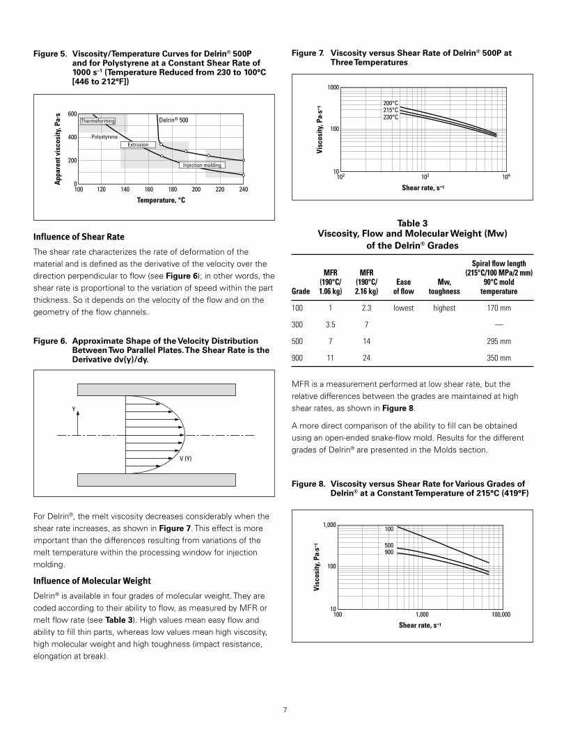
Figure 5. Viscosity/Temperature Curves for Delrin® 500P and for Polystyrene at a Constant Shear Rate of 1000 s–1 (Temperature Reduced from 230 to 100°C [446 to 212°F])
Temperature, °C
App
aren
t vis
cosi
ty, P
a.s
180 220 240200120 140 160100
600
400
200
0
Delrin® 500
Polystyrene
Thermoforming
Extrusion
Injection molding
Y
V (Y)
Figure 6. Approximate Shape of the Velocity Distribution Between Two Parallel Plates. The Shear Rate is the Derivative dv(y)/dy.
Figure 7. Viscosity versus Shear Rate of Delrin® 500P at Three Temperatures
Figure 8. Viscosity versus Shear Rate for Various Grades of Delrin® at a Constant Temperature of 215°C (419°F)
Influence of Shear Rate
Theshearratecharacterizestherateofdeformationofthematerialandisdefinedasthederivativeofthevelocityoverthedirectionperpendiculartoflow(seeFigure 6);inotherwords,theshearrateisproportionaltothevariationofspeedwithinthepartthickness .Soitdependsonthevelocityoftheflowandonthegeometryoftheflowchannels .
Shear rate, s-1
Visc
osity
, Pa·
s-1 200°C
215°C230°C
102 103 104
100
1000
10
Table 3 Viscosity, Flow and Molecular Weight (Mw)
of the Delrin® Grades
Spiral flow length MFR MFR (215°C/100 MPa/2 mm) (190°C/ (190°C/ Ease Mw, 90°C mold Grade 1.06 kg) 2.16 kg) of flow toughness temperature
100 1 2.3 lowest highest 170 mm
300 3.5 7 —
500 7 14 295 mm
900 11 24 350 mm
ForDelrin®,themeltviscositydecreasesconsiderablywhentheshearrateincreases,asshowninFigure 7 .Thiseffectismoreimportantthanthedifferencesresultingfromvariationsofthemelttemperaturewithintheprocessingwindowforinjectionmolding .
Influence of Molecular Weight
Delrin®isavailableinfourgradesofmolecularweight .Theyarecodedaccordingtotheirabilitytoflow,asmeasuredbyMFRormeltflowrate(seeTable 3) .Highvaluesmeaneasyflowandabilitytofillthinparts,whereaslowvaluesmeanhighviscosity,highmolecularweightandhightoughness(impactresistance,elongationatbreak) .
Shear rate, s-1
Visc
osity
, Pa·
s-1
100 1,000 100,000
100
1,000
10
900500
100
MFRisameasurementperformedatlowshearrate,buttherelativedifferencesbetweenthegradesaremaintainedathighshearrates,asshowninFigure 8 .
Amoredirectcomparisonoftheabilitytofillcanbeobtainedusinganopen-endedsnake-flowmold .ResultsforthedifferentgradesofDelrin®arepresentedintheMoldssection .
8
Hold-up time, min
Mel
t tem
pera
ture
, °C
60 80 10040200
200210220230240250
190
Minimum recommendedmelt temperature
Recommended operatingzone
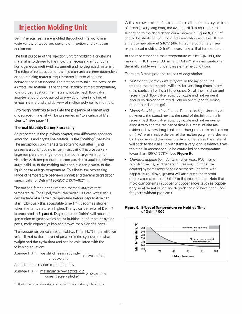
Figure 9. Effect of Temperature on Hold-up Time of Delrin® 500
Withascrewstrokeof1diameter(asmallshot)andacycletimeof1min(averylongone),theaverageHUTisequalto8min .AccordingtothedegradationcurveshowninFigure 9,Delrin®shouldbestableenoughforinjection-moldingwiththisHUTatamelttemperatureof240°C(464°F) .SomecustomershaveexperiencedmoldingDelrin®successfullyatthattemperature .
Attherecommendedmelttemperatureof215°C(419°F),themaximumHUTisover30minandDelrin®(standardgrades)isthermallystableevenundertheseextremeconditions .
Thereare3mainpotentialcausesofdegradation:
• Material trapped in Hold-up spots .Intheinjectionunit,trappedmoltenmaterialwillstayforverylongtimesinanydeadspotsandwillstarttodegrade .Soalltheinjectionunit(screw,backflowvalve,adaptor,nozzleandhotrunners)shouldbedesignedtoavoidHold-upspots(seefollowingrecommendeddesign) .
• Material sticking to “hot” steel .Duetothehighviscosityofpolymers,thespeednexttothesteeloftheinjectionunit(screw,backflowvalve,adaptor,nozzleandhotrunner)isalmostzeroandtheresidencetimeisalmostinfinite(asevidencedbyhowlongittakestochangecolorsinaninjectionunit) .Whereasinsidethebarrelthemoltenpolymeriscleanedbythescrewandthevalve,insideallotherareasthematerialwillsticktothewalls .Towithstandaverylongresidencetime,thesteelincontactshouldbecontrolledatatemperaturelowerthan190°C(374°F)(seeFigure 9) .
• Chemical degradation .Contamination(e .g .,PVC,flameretardantresins,acidgeneratingresins),incompatiblecoloringsystems(acidorbasicpigments),contactwithcopper(pure,alloys,grease)willacceleratethethermaldegradationofmoltenDelrin®intheinjectionunit .Notethatmoldcomponentsincopperorcopperalloys(suchascopper-beryllium)donotcauseanydegradationandhavebeenusedforyearswithoutproblems .
Injection Molding UnitDelrin®acetalresinsaremoldedthroughouttheworldinawidevarietyoftypesanddesignsofinjectionandextrusionequipment .
Thefirstpurposeoftheinjectionunitformoldingacrystallinematerialistodelivertothemoldthenecessaryamountofahomogeneousmelt(withnounmeltandnodegradedmaterial) .Therulesofconstructionoftheinjectionunitarethendependentonthemoldingmaterialrequirementsintermofthermalbehaviorandheatneeded .Thefirstpointtotakeintoaccountforacrystallinematerialisthethermalstabilityatmelttemperature,toavoiddegradation .Then,screw,nozzle,backflowvalve,adaptor,shouldbedesignedtoprovideefficientmeltingofcrystallinematerialanddeliveryofmoltenpolymertothemold .
Tworoughmethodstoevaluatethepresenceofunmeltandofdegradedmaterialwillbepresentedin“EvaluationofMeltQuality”(seepage11) .
Thermal Stability During Processing
Aspresentedinthepreviouschapter,onedifferencebetweenamorphousandcrystallinematerialisthe“melting”behavior .TheamorphouspolymerstartssofteningjustafterTgandpresentsacontinuouschangeinviscosity .Thisgivesaverylargetemperaturerangetooperate(butalargevariationofviscositywithtemperature) .Incontrast,thecrystallinepolymerstayssoliduptothemeltingpointandsuddenlymeltstotheliquidphaseathightemperature .Thislimitstheprocessingrangeoftemperaturebetweenunmeltandthermaldegradation(specificallyforDelrin®190–250°C[374–482°F]) .
Thesecondfactoristhetimethematerialstaysatthattemperature .Forallpolymers,themoleculescanwithstandacertaintimeatacertaintemperaturebeforedegradationcanstart .Obviouslythisacceptabletimelimitbecomesshorterwhenthetemperatureishigher .ThetypicalbehaviorofDelrin®ispresentedinFigure 9 .DegradationofDelrin®willresultingenerationofgaseswhichcausebubblesinthemelt,splaysonparts,molddeposit,yellowandbrownmarksontheparts .
Theaverageresidencetime(orHold-UpTime,HUT)intheinjectionunitislinkedtotheamountofpolymerinthecylinder,theshotweightandthecycletimeandcanbecalculatedwiththefollowingequation:
AverageHUT= weightofresinincylinder×cycletime
shotweight
Aquickapproximationcanbedoneby:
AverageHUT=maximumscrewstroke×2×cycletime
currentscrewstroke*
*Effectivescrewstroke=distancethescrewtravelsduringrotationonly

9
Screw DesignScrewdesignisakeyparameterforproductivity,becauseforcrystallinematerialsthescrewrotationtimeisaninherentpartofthecycletime .
Asmentionedabove,itshouldtakeinconsiderationthespecificmeltingbehaviorofthecrystallinematerial,i .e .,soliduptothemeltingpoint,highdemandofheatduringmeltingandlowviscosityofthemoltenmaterial .
Althoughgeneral-purposescrewsarewidelyusedformoldingDelrin®,optimumproductivitywillrequireaspecificdesign .Exceedingtheoutputcapabilityofaninadequatelydesignedscrewwillcausewidetemperaturevariationsandunmeltedparticles(sometimesunmeltanddegradedmaterialhavebeenobservedatthesametime) .Theresultislossoftoughness,variabilityinshrinkageanddimensions,warping,surfacedefects,pluggedgates(leadingtoshortshots)orothermoldingproblems .
Duetothespecificsofthemeltingprocessofacrystallinepolymer,ascrewdesignedforDelrin®willhaveshallowflightdepthsinthemeteringsectionandaslightlyhighercompressionthanageneral-purposescrew .SpecificsuggestionsaregivenforvariousscrewdiametersandcompositionofDelrin®acetalresininTable 4 .Compressionratioistheratioofvolumeofoneturninthefeedsectiontothatinthemeteringsection(canbeap-proximatedtotheratioofthedepthofthetwozones) .
Thelengthofthescrewwillalsoaffectthemeltquality(aninsulatingmaterialneedssometimetogetthethermalenergytransferredeveniftheshearcontributestotheheatingprocess) .Thepreferredlengthisabout20timesthescrewdiameteror20turnswhenthepitchanddiameterareequal .Thescrewshouldbedividedasfollows:30–40%(6–8turns)feedsection,35–45%(7–9turns)transitionand25%(5turns)metering
Table 4 Screw Design for Delrin® Acetal Resins
Medium and Low Viscosity Grades: Delrin® 500P, 900P, 500T High Viscosity Grades of Delrin®: Delrin® 100P, 100ST
Nominal diameter (D) Depth of feed section (h1) Depth of metering section (h2) Depth of feed section (h1) Depth of metering section (h2) mm mm mm mm mm 30 5.4 2.0 5.2 2.6 45 6.8 2.4 6.5 2.8 60 8.1 2.8 7.5 3.0 90 10.8 3.5 8.7 3.6 120 13.5 4.2 (in) (in) (in) (in) (in) (1-1⁄2) (0.240) (0.087) (0.230) (0.105) (2) (0.290) (0.100) (0.270) (0.115) (2-1⁄2) (0.330) (0.110) (0.300) (0.120) (3-1⁄2) (0.420) (0.140) (0.340) (0.140) (4-1⁄2) (0.510) (0.160)
D h1
FEED SECTION
Pitch h2
METERINGSECTION
TRANSITION
(20/1 Length/Diameter Ratio)
section .Screwswith20turnsarecommonlydividedinto7turnsfeed,8turnstransitionand5turnsmetering .Inscrewslessthan16diameterslong,itmaybenecessarytoreducethepitchtogetupto20turns .Definitively,thefeedsectionshouldneverbelessthan6turns .
TherelativelyhighcompressionratioscrewssuggestedforDelrin®aredesignedtoincreasetheheatinputbymechanicalworkingoftheresin .Becausetheenergyforthisincreasecomesfromthescrewmotor,additionalhorsepowermustbeavailableifanincreaseinmeltingcapabilityistoberealized .
Screw Size
Theidealscrewsizeisdeterminedbythevolumeofthecurrentshot .Optimumproductivitywillbeachievedwhentheshotsizerequiresascrewtravelduringplasticizationequaltoorlowerthan50%ofthecapacityoftheinjectionunit .Otherwise,screwrotationspeedwillhavetobedecreasedattheendofthetraveltoguaranteeanhomogeneousmelt,leadingtoalossinproductivity .Practically,optimumproductivityisachievedwithascrewtravelofbetween1and2diametersofthescrew .
Thermalsettingsoftheinjectionunitwillbedependentontheresidencetime(HUT)andhencedependentonthecycletime .Ruleswillbepresentedunder“MoldingProcess .”
Screw Design for the Use of Color Concentrate
Aflowanalysisshowsthatthemajorpartoftheflowinthescrewislaminar,thendividedinthebackflowvalve(duetothechangesinflowdirection),andstilllaminarintheadaptor,nozzle,sprue,etc .Togetoptimummeltquality,todispersepigmentsandcolorconcentrates,itisstronglyrecommendedtoaddamixinghead .Thepurposeofaproperlydesignedmixingheadisnottomixmaterialbyturbulence(turbulentflowisimpossiblewithhighlyviscousmoltenpolymer),butbyforcedchangesinflowdirection .

10
ELCee™ Screw for Optimum Productivity AnothersolutiontoachieveoptimumproductivitywhenmoldinghighlycrystallineresinssuchasDelrin®,istouseaspecialscrewdesignedbyDuPontcalledthe“ELCee™screw”(patentappliedfor) .TheELCee™screwisdesignedtocapitalizeontherheologicalcharacteristicsofresinswithbettercontrolofshearonthemelt,makingthescrewmoreefficient .Thisallowsthemoldertorunthemoldingmachinesatfastercyclesandproducepartsofhigherquality .(ConsultyourlocalDuPontrepresentativeformoreinformation .)
Cylinder Temperature ControlThisisdeterminedbythemachinemanufacturer,buttwocommentsshouldbemade .
• Thetemperaturecontrolshouldprovideatleastthreeindependentzones,withthermocouplesplacednearthecenterofeachzone .Burn-outofoneormoreheaterbandswithinazonemaynotbereadilyapparentfromthetemperaturecontrollers,sosomemoldershaveusedammetersineachzonetodetectheaterbandmalfunctions .
• UsuallyforDelrin®thereisnoneedtocoolthefeedthroat,butincasesuchaneedexists,thewaterflowshouldbekepttoaminimum .Overcoolingthefeedthroathasbeenobservedasamajorreasonforcontaminationbyblackspecks .Thesearegeneratedinthebarrel,betweenthefirstandsecondheatingzones,withthefollowingmechanism(seeFigure 10) .ThethermocoupleTC1isinfluencedbythelowtemperatureduetoexcessivecooling,andthesystemwillrespondbyswitchingONtheheatingbandsHB1andHB2 .ThiscausesnoproblemwithHB1,butresultsinoverheatinganddegradationintheareaunderHB2 .Toreducetheriskofformationofblackspecks,thefollowingrecommendationsshouldbeobserved:
a) thefeedthroatcoolingshouldbelimitedtoaminimumtemperatureof80–90°C(176–194°F);
b) theheaterbandHB2shouldbecontrolledbyTC2,orTC1shouldbeplacedinthemiddleofHB2,orHB2shouldhavehalfthepowerdensityofHB1 .
HB1 HB2
TC1
Cooling channels Contaminationsource
TC2 TC3 TC4
HB3 HB4 HB5 HB6 HB7
HB8
Figure 10. The Risk of Black Specks Contamination That Could Arise From the Presence of a Cooling System of the Feed Throat
Figure 11. Design of Adaptor and Non-Return Valve
Cylinder AdaptorTheadaptorshowninFigure 11isdesignedtoavoidholdupareasandflowrestrictions,thetwomaincausesofdegradationandproblemslinkedtothisarea .NotethattheconceptisthesameforscrewedadaptorsasrepresentedinFigure 11(usedforsmallscrews≤∅40mm)andforboltedadaptors(usedforlargerscrews) .Theadaptorshasshortcylindricalsections(AandB)whereitjoinsboththenozzleandthecylindertomaintainaccuratematchingofthesediameters,evenifitbecomesnecessarytorefacethematingsurfaces .Thematingsurfaces(C)shouldbenarrowenoughtodevelopagoodsealwhenthenozzleoradaptoristightenedandyetwideenoughtoavoiddeformation .Inadditiontoitsmechanicalfunctionofreducingthediameter,theadaptoractstoisolatethenozzlethermallyfromthefrontofthecylinderforbettercontrolofnozzletemperature .Aseparateadaptor,madeofsoftersteelthantheoneusedforthecylinder,iseasierandlessexpensivetorepairandchangethanacylinder .Italsoprotectsthecylinderfromdamageduetofrequentchangingofthenozzle .Withtheboltedadaptor,specialcareshouldbetakenduringassemblytoensureparallelism(don’tovertightenscrewsfromonesideonly) .
Nozzle
Adaptor
A
D HE
B
G FC
Non-Return Valve (Back Flow Valve—BFV) Thenon-returnvalveorcheckringshowninFigure 11preventsmeltfromflowingbackwardduringinjection .Thisunitisfrequentlynotproperlydesignedtoeliminateholdupofresinandflowrestrictions .Malfunctioningthatallowsresinbackflowisalsoacommonexperienceandiscausedbypoordesignormaintenance .Aleakingnon-returnvalvewilladdtoscrewretractiontime,whichcanincreasecycle,anditwillalsocausepoorcontrolofpackinganddimensionaltolerances .
Thenon-returnvalvemustmeetthefollowingrequirements:
• Noholdupspots
• Noflowrestrictions
• Goodseal
• Controlofwear

11
Figure 12. Reverse Taper Nozzle
Heater Band
Thermocouple well
A
B
Thermocouple wellHeater BandA B
Figure 13. Straight Bore Nozzle, Only for Machines Without Screw Decompression
Theserequirementsareprovidedforinthenon-returnvalveshowninFigure 11 .
Theslotsorflutes(D)inthescrewtiparegenerouslyproportioned,andthespace(E)betweenthecheckringandtipissufficientforresinflow .
Theseatingofthefixedringiscylindricalwhereitjoinsboththeendofthescrew(F)andthescrewtip(G)topermitaccuratematchingofthesediametersandavoidholdup .
Thescrewtipthreadhasacylindricalsection(H)aheadofthethreadsthatfitscloselyinamatchingcounterboreforsupportandalignmentofthescrewtipandseatring .
Thescrewtipandcheckringseatshouldbeharder(aboutRc52)thanthefloatingring(Rc44),becauseitislessexpensivetoreplacethefloatingringwhenwearoccurs .
Corrosionresistantsteelissuggestedforthetip .Goodmatchingofcylindricaldiametersisessentialtoavoidholdupspots .
NozzleAswithothersemi-crystallinepolymers,Delrin®maydroolfromthenozzlebetweenshotsifthenozzleistoohot,oritmayfreezeiftoomuchheatislosttothespruebushing .
ThenozzledesignshowninFigure 12cansolvetheseproblems .Thefollowingshouldbeconsidered:
1 . Theheaterband(A)shouldextendasclosetothenozzletipaspossibleandcoverasmuchoftheexposedsurfaceaspractical .Thiscounteractsanyheatloss,especiallyheatlosstothespruebushing .
2 . Thethermocouplelocationisimportant .Anappropriatelocation(B)isshowninthesamepicture .
3 . Adequatetemperatureuniformityisrequiredsothatlocaloverheatingorprematurefreezingisavoided .
4 . Topreventpolymerdegradationthesteeltemperatureshouldnotexceed190°C(374°F) .
5 . Thenozzleheatershouldhaveitsownindependenttemperaturecontroller .
Screwdecompressionor“suckback”isfrequentlyusedtomakecontrolofdrooleasierwiththeseopennozzles .Thisfeatureisavailableinmostmachines .
Whennotavailable,adesignsuchastheoneillustratedinFigure 13shouldbeused .
AlthoughshutoffnozzleshaveoccasionallybeenusedsuccessfullywithDelrin®,theytendtocauseholdupofresinthatresultsinbrownstreaksorgassing,especiallyaftersomewearhasoccurredinthemovingpartsofthenozzle .ThesenozzlesarenotgenerallyrecommendedforDelrin®onsafetygroundsalone .
Note:Withalongnozzle,thethermocouplewellBshouldbepositionedinthemiddleofthenozzleandnotatthebackofthenozzle .
Evaluation of Melt QualityBelowarepresentedtwoquickandeasyteststoevaluatethemeltqualitydeliveredbytheinjectionunit .Althoughtheresultislinkedwiththetemperaturesettingoftheinjectionunit,itisalsohighlydependentonthedesignoftheinjectionunit .
Foaming Test
Thefoamingtestisrecommendedtodeterminethequalityoftheresinaftermeltingintheinjectionunit,i .e .,thequalityoftheresinANDthequalityoftheinjectionunit .
Procedure:
1 . Whenthemachineisrunningincycle,stopthemachineafterscrewretractionfor3minforpigmentedDelrin®(10minfornaturalmaterial) .
2 . Purgeatlowspeed(toavoidhotsplashes)intoacupandobservethemoltenmaterialfor1or2min .Thenputthemoltenmaterialinabucketofwater .
3 . Thenrechargethescrewandwait2moreminutes(10moreminutesfornaturalmaterial) .
4 . Repeatoperation2 .

12
Anunstablemeltwillgrow(foam)duringtheobservationandfloatinthebucket .Astablemeltwillstayshinywithatendencytoshrinkduringtheobservation,andwillsinkinthebucket .
Foamingresinwillquicklycausemolddepositandwillacceleratescrewdeposit,whichmayleadtoblackspeckcontamination .
Thistechniqueisusefultoevaluatenon-DuPontcolorsystems(colormasterbatches,liquidcoloring) .
Thefoamingtestcanalsobeusedtodetectinadequatequalityoftheinjectionunit(e .g .,problemsofthroatcoolingandconsequentoverheating,excessivenozzletemperature,hold-upspots,etc) .
Unmelt Test
Theunmelttestisrecommendedtoevaluatemelthomogeneity:
• Whenthepressisrunningoncycle,stopattheendofacycleandpurgeoneshot;
• chargethescrewimmediatelywiththeshotvolumeusedandpurgeagain;
• repeattheoperationuntildetectionoflumps/irregularitiesinthepurgecomingoutofthenozzle .
Ifsuchlumps/irregularitiesappearafterlessthan3purges,theriskofunmeltisveryhighandshouldbedealtwithbyincreasingcylindertemperature,byloweringscrewRPMandbyincreasingbackpressure .Ifsuchchangeslengthenthecycletimetoomuch,amoreappropriatescrewdesignshouldbeused(seeTable 4) .Iflumps/irregularitiesappearafter3purgesbutbefore6,thesituationisacceptable,butthereisnotmuchsafetymargin .Iftheyappearafter6purges,thereisaverylowriskofunmelt .
13
Figure 14. Exploded View of Mold
LocatingRing
SprueBushing
FrontClampingPlate
FrontCavityPlate(“A”Plate)
LeaderPins
LeaderPinBushingsRearCavityPlate(“B”Plate)
SupportPlate
Cavity
SpacerBlock
EjectorRetainerPlate
ReturnPinEjectorPlateKnockOutPins
RearClampingPlateSpruePullerSupportingPullerStopPin
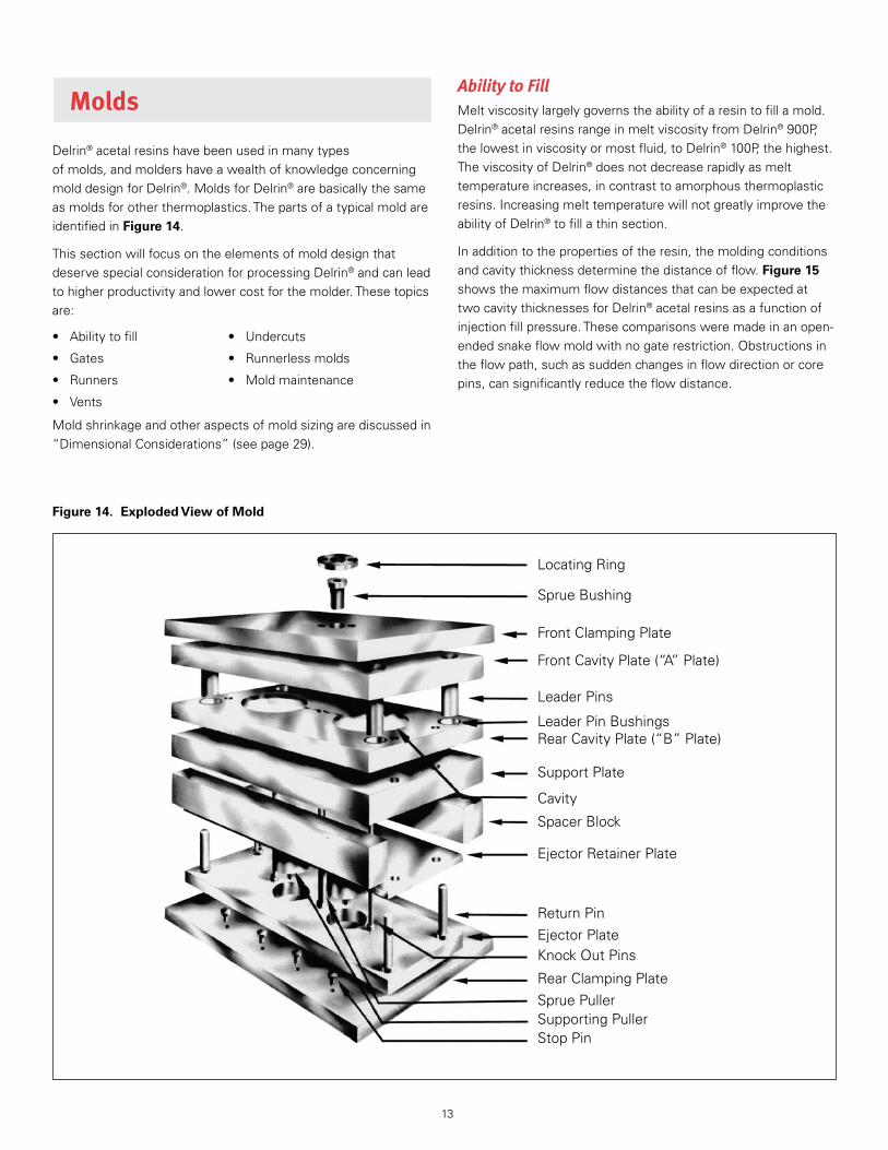
Ability to FillMeltviscositylargelygovernstheabilityofaresintofillamold .Delrin®acetalresinsrangeinmeltviscosityfromDelrin®900P,thelowestinviscosityormostfluid,toDelrin®100P,thehighest .TheviscosityofDelrin®doesnotdecreaserapidlyasmelttemperatureincreases,incontrasttoamorphousthermoplasticresins .IncreasingmelttemperaturewillnotgreatlyimprovetheabilityofDelrin®tofillathinsection .
Inadditiontothepropertiesoftheresin,themoldingconditionsandcavitythicknessdeterminethedistanceofflow .Figure 15showsthemaximumflowdistancesthatcanbeexpectedattwocavitythicknessesforDelrin®acetalresinsasafunctionofinjectionfillpressure .Thesecomparisonsweremadeinanopen-endedsnakeflowmoldwithnogaterestriction .Obstructionsintheflowpath,suchassuddenchangesinflowdirectionorcorepins,cansignificantlyreducetheflowdistance .
Molds
Delrin®acetalresinshavebeenusedinmanytypesofmolds,andmoldershaveawealthofknowledgeconcerningmolddesignforDelrin® .MoldsforDelrin®arebasicallythesameasmoldsforotherthermoplastics .ThepartsofatypicalmoldareidentifiedinFigure 14 .
ThissectionwillfocusontheelementsofmolddesignthatdeservespecialconsiderationforprocessingDelrin®andcanleadtohigherproductivityandlowercostforthemolder .Thesetopicsare:
• Abilitytofill • Undercuts
• Gates • Runnerlessmolds
• Runners • Moldmaintenance
• Vents
Moldshrinkageandotheraspectsofmoldsizingarediscussedin“DimensionalConsiderations”(seepage29) .

14
GatesThegatesofamoldplayamajorroleinthesuccessorfailureofamoldingjob .Thelocation,design,andsizeofagatearekeyfactorstoallowoptimumpacking .Obviously,thedesignwillbedifferentthantheoneusedformoldingamorphousmaterial .Inthatcasetheflowshouldstopassoonaspossibleafterfillingthecavitytoavoidoverpacking(flowin)andsinkmarksatgate(flowback) .Withcrystallinematerial,thelocation,designandsizeofthegateshouldbesuchthatitwillallowacontinuousflowduringALLthepackingphase(Holdpressuretime—seepage27) .
Gate Location
Asakeyrule,whenapartisnotuniforminwallthickness,thegatemustbelocatedinthethickestsection .Therespectofthisbasicprincipleplaysanessentialroleinobtainingoptimumpackingandconsequentlythebestmechanicalproperties,dimensionalstabilityandsurfaceaspect .Ofcourseeverybottleneck(reducedsectionalongtheflowofthemelt)shouldbeavoidedbetweenthegateandallareasofthepart .
Anareawhereimpactorbendingwilloccurshouldnotbechosenasthegatelocation,becausethegateareamayhaveresidualstressandbeweakenedsinceitworksasanotch .Similarly,thegateshouldnotcauseaweldlinetooccurinacriticalarea .
Thegateshouldbepositionedsothattheairwillbeswepttowardapartinglineorejectorpin—whereconventionalventscanbelocated .Forexample,aclosed-endtubesuchasapencapshouldbegatedatthecenteroftheclosedend,soairwillbeventedatthepartingline .Anedgegatewillcauseairtrappingattheoppositesideneartheclosedend .Whenweldlinesareun-avoidable,forexamplearoundcores,anescapeforgasesmustbeprovidedtoavoidseriousweaknessandvisualflaws .Specificrecommendationsforventingaregivenlaterinthissection .
AnotherconsiderationinchoosingagatelocationforDelrin®issurfaceappearance .Gatesmearorblush,aswellasjetting,areminimizedbylocatingthegatesothatthemeltenteringthecavityimpingesagainstawallorcorepin .
Acentralgatelocationisoftennecessarytocontrolroundnessofgearsandothercriticalcircularparts .Multiplegates,usuallytwotofour,arecommonlyusedwhenthereisacentralholetoavoidadifficult-to-removediaphragmgate .
Gate Design
Asmentionedabove,forcrystallinematerialslikeDelrin®thethicknessofthegateoritsdiameter(forapin-pointgateortunnelgate)determinesthefreeze-offtime,andthereforealsodetermineswhetheritispossibletopackthepart(tocompensatethevolumereductionduetocrystallization)andmaintainthepressureduringsolidification .Thegateshouldremainopenuntilthepartdensityismaximumforaspecificmaterial .Thethickness(ordiameter)ofthegateshouldamountto50–60%ofthewallthicknessatthegate .Thewidthofthegateshouldalwaysbeequalorgreaterthanthegatethickness .Thelengthofthegateshouldbeasshortaspossibleandneverexceed0 .8mm(0 .03in) .Thegateareaofthepartshouldnotbesubjectedtobendingstressesduringactualservice .Impactstressesareparticularlyliabletocausefailureinthegatearea .
ThemostcommontypesofgatesaresummarizedinFigure 16 .
• DIAPHRAGMGATE:Circulargateusedtofillasinglesymmetricalcavity .Theadvantagesareareductionofweldlineformationandimprovementoffillingrates .Howevertheparthastobemachinedtoremovethegate .
• DIRECTGATE:Thespruefeedsdirectlyintothemoldcavitywithoutrunners .Thisdesignmayoftenleadtosurfacedefectscomingfromthenozzle(e .g .,coldslug,coldskin,entrappedair .)
• EDGEGATE:Usualtypeofgatewithtwoplatemolds .Itisnotselfdegating .
• FANGATE:Thisgateisusedtoenlargetheflowfront .Usuallyitleadstoareductionofstressconcentrationsinthegatearea .Lesswarpageofpartscanusuallybeexpectedbytheuseofthisgatetype .
• PINPOINTGATE:Thisgateisusedwiththreeplatemolds .Itisselfdegating .
Injection pressure, MPa
Flow
dis
tanc
e, m
m
Flow
dis
tanc
e, in
12080 100
Injection pressure, psi17.40011.600 15.000
500 –20
–15
–10
–5
600
400
300
200
100
0
100
100ST
100
500100ST
900
500
900
2.5 mm (0.100 in)1 mm (0.04 in)
Figure 15. Maximum Flow Distance of Delrin® Acetal Resins

15
Diaphragm gate
Submarine gate(bucket type)
Direct gate
Edge gate
Fan gate
Fan gate
Pin point gate
Ring gate
Figure 16. Schematic View of the Most Common Types of Gates
Figure 17. Details of a Typical Edge Gate Suitable for Delrin®
Runner
Side View
z = Max. 0.8 mm
T = Part ThicknessT
x = 0.5T
T+1.0
D1
30°
D
D1
d
T
Figure 18. Details of a Submarine Gate (Tunnel Gate) Adequate for Delrin® (left side). The One on the Right is Not Adequate for Crystalline Polymers and Would Give Problems with Delrin®.
• RINGGATE:SeeDIAPHRAGMGATE .
• SPRUEGATE:SeeDIRECTGATE .
• SUBMARINEGATE:Atypeofedgegatewheretheopeningfromtherunnerintothemoldisnotlocatedonthemoldpartingline .Itisusedtoseparatethegatefromthepartwithatwoplatemold(self-degating) .
• TUNNELGATE:SeeSUBMARINEGATE .
DetailsofatypicaledgegatesuitableforDelrin®areshowninFigure 17 .
Figure 18showsdetailsofasubmarinegateadequateforDelrin®(left),comparedtoasimilartypeofgatenotrecommendedforcrystallinematerials(right) .
Design criteria:
• alwaysgateinthickestareaofthepart;
• diameterofthegate“d”mustbeatleasthalfthepartthickness .Thelengthmustbeshorterthan0 .8mm(0 .03in)topreventprematuregatefreezingduringpacking;
• theinscribeddiameter“D”ofthetunnelnexttothegatemustbeatleast1 .2×thepartthickness“T .”
ThegateshownontherightsideofFigure 18isnotrecommendedforcrystallinematerialslikeDelrin®,becausesuchconicalgatesectionscrystallizebeforetheendofcompletepartpackout .Thisresultsinlowmechanicalperformanceanduncontrolledshrinkage .
Figure 19showsdetailsofathreeplategatedesignadequateforDelrin®(left),comparedtoasimilartypeofgatenotrecommendedforcrystallinematerials .Thedesigncriteriaillustratedabovearealsoapplicabletothiskindofgate .
Note:Restrictionsaroundthespruepullerwillleadtoincompletepartpackout .So,thediameterD1inFigure 19shouldbeatleastequaltodiameterD .

16
Runner SystemGuidelines
Keyguidelinestofollowwhendesigningarunnersysteminclude:
a . runnersshouldstayopenuntilallcavitiesareproperlyfilledandpacked;
b . runnersshouldbelargeenoughforadequateflow,minimumpressurelossandnooverheating;
c . runnersizeandlengthshouldbekepttotheminimumconsistentwithpreviousguidelines .
Eachofthesefactorscanaffectqualityandcostofmoldedparts .Factor(a)shouldberegardedasthemostcritical .
Thecrosssectionoftherunnersismostoftentrapezoidal,whichrepresentsanoptimumpracticalcompromisewithrespecttothefullroundsection .Theeffectivecrosssectionoftherunnerisinthiscasethediameterofthefullcirclethatcanbeinscribedinit .
ForpartsofDelrin®tohavethebestphysicalproperties,therunnersnexttothegatemusthaveatleastaninscribeddiameterthepartthickness“T+1mm .”
Whenthemoldingsareverythin,however,thisrunnercannotbelessthanabout1 .5mm(0 .06in)inthickness .Therunnerthicknessisusuallyincreasedateachofthefirstoneortwoturnsfromthecavity,asshownintheexampleofFigure 20 .
Figure 21. Direct Gating (Left) and Indirect Gating to Break the Flow (Right), in a One-Cavity Mold
Figure 22. Balanced (Left) and Unbalanced (Right) Runner Systems in a 16-Cavity Mold
Single Cavity Mold
Thesimplestrunnerconfigurationforasinglecavitymoldcouldbedirectgating(seeFigure 21) .Inthiscase,however,itwouldbenecessarytohavea“coldslugcatcher”directlyonthepart,withassociatedsurfaceproblemsandlowermechanicalpropertiesinthatarea .Thepreferredsolutionisthento“breaktheflow”asindicatedinFigure 21 .
Runner Layout
Aperfectlybalancedlayout(withequalflowdistancefromthespruetoeachcavity)isbestachievedifthenumberofcavitiesisequaltoapowerof2(2,4,8,16,32,64,128,etc .) .Seeanexampleofa16-cavitymoldinFigure 22withbalanced(left)andunbalancedrunnersystems .Aperfectlybalancedlayoutmaybeimpracticalandexpensive .
D
d
2°
D1
T*
Figure 19. Details of a Three Plate Gate Design Adequate for Delrin® (Left Side). The One on the Right is Not Adequate for Crystalline Polymers and Would Give Problems with Delrin®. *Gate Length Should be <0.8 mm (0.03 in).
Figure 20. Correct Runner Thickness for an Eight Cavity Mold
Ø1 = D1 + 1 mm
Ø3 = D1
Ø2 = D1 + 0.5 mm

17
Figure 23. Examples of Unbalanced 16-Cavity Mold. The Solution on the Right is Provided with Overflow Wells to Trap Cold Slugs.
Figure 24. Example of “Spiral Effect” in a 32-Cavity Mold. Cavities 11, 14, 19, 22 Will Be Filled First and May Show Splays and Mold Deposits.
1
16 14
1917
32
24
9
22
11
25
8
Figure 25. Sprue and Nozzle Design Often Used with Delrin®. The Dimensions are Linked with the Dimensions of the Part and of the Runners.
Figure 26. Example of a Design of a Nozzle Without Sprue Used with 2 Plate Molds. Remember that for Delrin® the Nozzle Temperature Should Not Exceed 190°C (374°F).
D N1D N2
Ø1
D N1
D N2
5 mm
Whenanunbalancedrunnersystemisselected,thelayoutshowninFigure 23(left)couldpresentmorerisksofqualityproblems .Theflowtendstostopateachoftheearlygatesduetotherestrictionandthematerialstartstocrystallize .Then,astherunnercontinuestobefilled,thepressurerisesandthethecoldslugswhichstartedtobebuiltup,arepushedintothecavity .
Toreducesuchrisk,thesolutionshowninFigure 23(right)isrecommended .Insuchconfiguration,thecoldslugstendtobetrappedintoeachoverflowwell .
Incaseofmulti-cavitymolds(≥16cavities),theso-called“spiraleffect”couldtakeplaceinthe“internal”cavitiesofthelayout(seeforinstanceFigure 24),duetoover-heatingofthemeltinrunners,causedbylocalizedshear .Tominimizenegativeeffectlikesplaysormolddeposit,shearshouldbereducedbyusingappropriaterunnerdimensions .
Formulti-cavitymoldsforsmallthicknessparts(≤1mm[0 .04in]),thedesignofrunnersshouldbecheckedbyrunningadetailedflowanalysisstudy .
Nozzle and SprueNozzleandspruediametersaredirectlylinkedwiththedimensionsofthepartandoftherunners .Thedesignershouldfirstdecideifthesprueisneededornot .Ifyes,adesignliketheoneshowninFigure 25couldbeselected,onethatinmanycaseshasprovedtobethemosteffectivewithcrystallinematerialslikeDelrin® .Duetoitsparallelcylindricalshapeitiseasytomachineandpolish,allowslargenozzlediameters,anditiseasytoejectduetohighshrinkage .Guidelinesforthedimensionare:
• aspruediameter∅1atleastequaltotheinscribeddiameterofthemainrunner;
• anozzlediameter“DN1”equalto∅1minus1mm .
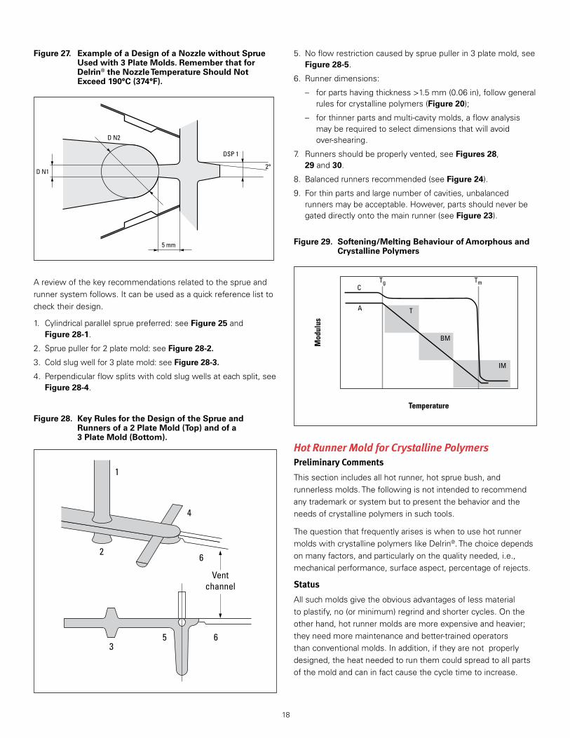
Incasethedesignerselectsadesignwithoutasprue,alongnozzlemayberequiredasshowninFigure 26fora2platetool,andinFigure 27fora3platetool .Again,thedimensionsarelinkedtothedimensionsofthepartandoftherunners(guideline:nozzlediameter“DN1”equalstothemainrunnerinscribeddiameterminus1mm) .
18
Areviewofthekeyrecommendationsrelatedtothesprueandrunnersystemfollows .Itcanbeusedasaquickreferencelisttochecktheirdesign .
1 . Cylindricalparallelspruepreferred:seeFigure 25andFigure 28-1 .
2 . Spruepullerfor2platemold:seeFigure 28-2.
3 . Coldslugwellfor3platemold:seeFigure 28-3.
4 . Perpendicularflowsplitswithcoldslugwellsateachsplit,seeFigure 28-4 .
Temperature
Mod
ulus
C
A T
BM
IM
Tg Tm
Figure 29. Softening/Melting Behaviour of Amorphous and Crystalline Polymers
5 . Noflowrestrictioncausedbyspruepullerin3platemold,seeFigure 28-5 .
6 . Runnerdimensions:
– forpartshavingthickness>1 .5mm(0 .06in),followgeneralrulesforcrystallinepolymers(Figure 20);
– forthinnerpartsandmulti-cavitymolds,aflowanalysismayberequiredtoselectdimensionsthatwillavoidover-shearing .
7 . Runnersshouldbeproperlyvented,seeFigures 28,29and30 .
8 . Balancedrunnersrecommended(seeFigure 24) .
9 . Forthinpartsandlargenumberofcavities,unbalancedrunnersmaybeacceptable .However,partsshouldneverbegateddirectlyontothemainrunner(seeFigure 23) .
Hot Runner Mold for Crystalline PolymersPreliminary Comments
Thissectionincludesallhotrunner,hotspruebush,andrunnerlessmolds .Thefollowingisnotintendedtorecommendanytrademarkorsystembuttopresentthebehaviorandtheneedsofcrystallinepolymersinsuchtools .
ThequestionthatfrequentlyarisesiswhentousehotrunnermoldswithcrystallinepolymerslikeDelrin® .Thechoicedependsonmanyfactors,andparticularlyonthequalityneeded,i .e .,mechanicalperformance,surfaceaspect,percentageofrejects .
Status
Allsuchmoldsgivetheobviousadvantagesoflessmaterialtoplastify,no(orminimum)regrindandshortercycles .Ontheotherhand,hotrunnermoldsaremoreexpensiveandheavier;theyneedmoremaintenanceandbetter-trainedoperatorsthanconventionalmolds .Inaddition,iftheyarenotproperlydesigned,theheatneededtorunthemcouldspreadtoallpartsofthemoldandcaninfactcausethecycletimetoincrease .
Figure 27. Example of a Design of a Nozzle without Sprue Used with 3 Plate Molds. Remember that for Delrin® the Nozzle Temperature Should Not Exceed 190°C (374°F).
Figure 28. Key Rules for the Design of the Sprue and Runners of a 2 Plate Mold (Top) and of a 3 Plate Mold (Bottom).
D N1
D N2
DSP 1
2°
5 mm
1
4
6
Ventchannel
2
35 6

19
Oneapproachistoevaluatetheexpectedincreaseoftheoreticalproductivityversusconventionalmolds .Ifsuchanincreaseislowerthan25%,itwouldbewisetostaywitha3platemoldthatwillbecheapertobuild,startandrun .
Thebreak-evenofabout25%appliestofullhot-runnersystems;forothermolds(withhotspruebushes,coldsub-runners)thebreak-evenpointismuchlower .
Direct Gating Versus Cold Sub-Runners for Crystalline Polymers
Whendesigningahotrunnermoldforcrystallinepolymers,itshouldbekeptinmindthatdirectgatingviahotrunnerismoredifficultwithcrystallinepolymersthanwithamorphousones .Thedifferencecomesfromthesofteningormeltingbehaviorofthesetwotypesofpolymers .
AnamorphousmaterialexhibitsagradualsofteningbehavioraboveTgfromthesolidstatetotheliquidstate,allowingawideprocessingwindowintermsoftemperatureandviscosity .Infact,asitstemperatureincreasesaboveTg(seeFigure 29)anamorphouspolymer(curve“A”)lendsitselffirsttothermoforming(“T”),thentoblowmolding(“BM”)andfinallytoinjectionmolding(“IM”) .
Vent LandEnd of flow
Vent channels
L 0.8 mm
W > 2 mm
D < 0.03 mm
* 0.3 mm
Figure 30. Recommended Venting of a Part and of its Runner System
Onthecontrary,theTghasusuallyalimitedornegligibleeffectonthestructureofcrystallinepolymers,whicharesolidaboveTg .AtthetemperatureTm,crystallinepolymersmeltsharplyandbecomeliquid(curve“C”) .
Suchbehaviorofacrystallinematerialmayinvolvetheriskof:
• Droolingaroundthegatewithconsequentproblemsofbadsurfaceaspectanddeformation .
• Pluggingofthegatesbysolidifiedmaterial,plugswhichwillbepushedintothecavities,withconsequentproblemsofsurfacedefectsandlowermechanicalperformances .ThebestwaytopreventsuchproblemsistouseCOLDSUB-RUNNERS .
Thermal Control of Hot Runner Molds
Thermalmanagementandstreamliningoftheflowareveryimportantforhotrunnertools .Itshouldbecheckedthatarelativelylowtemperaturesetting(≤190°C[≤374°F])givesaneasyflowofthematerialwithnohold-upspots .
Thereasonisthat,duetotheviscosityofthepolymer,itsflowisalwayslaminar .Thismeansthatthematerialwillremainagainstthesteelwallofthehotrunner,andresidencetimewillbeverylong .ForDelrin®,toavoidthermaldegradationwithprolongedtimes,thesteeltemperatureshouldneverexceed190°C(374°F) .Ifthehotrunnersystemsolidifiesatthattemperature,thenitmustbemodifiedtoimprovethermalinsulationandheatdistributiontoremovecoldspots .Degradationcanresultinsplays,odor,blackspecksandmolddeposit .
Conclusions
WithcrystallinepolymerssuchasDelrin®,werecommendthefollowing:
• Aminimumof25%theoreticalcostdecreaseshouldbeexpectedbeforeahotrunnerisconsidered .
• Highlytrainedmachineoperatorsandmoldmaintenancetoolmakersshouldbeavailable .
• Useofcoldsub-runners,neverdirectgatingstraightontothepart .
• UseofDelrin®Pgrades .
• Alltemperaturesinthehotrunnersystemmustnotexceed190°C(374°F) .
• Avoidtheuseofhotrunnermoldsifsurfacedefectsarenotacceptableandhighpartmechanicalperformanceisrequired .
• Avoidtheuseofhotrunnersfortoughenedgrades .
VentsVentingamoldforDelrin®isparticularlyimportant,andspecialattentionshouldbegiventothisfactorduringboththedesignofthemoldanditsinitialtrial .ThisattentionisrequiredbecauseburningofpartscausedbyinadequateventingisnoteasilyobservedwithDelrin® .Withotherresins,poorventingresultsinablackenedandburnedspotonthepart .WithDelrin®,however,theremaybeeithernovisibleflaworaninconspicuouswhitishmarkonthemolding .

20
VentingproblemswithDelrin®acetalresinsmaybemademoreobviousbysprayingthemoldwithahydrocarbonorkerosene-basedsprayjustbeforeinjection .Ifventingispoor,thehydrocarbonwillcauseablackspotwheretheairistrapped .Thistechniqueisparticularlyusefulfordetectingpoorventsinmulti-cavitymolds .Aconvenientsourceofhydrocarbonsprayisarustpreventativespray .
Ventsshouldbelocatedat:
1 . theendofanyrunner;
2 . anyflowjunctionwhereairisentrappedandaweldlineresults .Thepositionofweldlinescanbedefinedbyshortshots .
OnlyNOventingtogetherwithexcessivefastinjectionspeedwillcausecorrosionofthetoolattheweldlineswithDelrin®(dieseleffect) .InadequateventingofmoldsforDelrin®maycauseagradualbuildupofmolddepositwhereventsshouldbelocatedandinmoldcrevicesthroughwhichlimitedventinghastakenplace .Thesedepositsconsistofawhitesolidmaterialformedfromthetracesofgasevolvedduringnormalmolding .Goodventsallowthisgastoescapewiththeairfromthecavities .
Poorventingmayalsoreducephysicalpropertiesatweldlines .
Ventingproblemsmaybeaggravatedbyhighmelttemperature,longholduptime,orholdupareasintheinjectioncylinder,whichwillgeneratemorethannormalamountsofgas .Fastinjectionfillspeedwillalsoaggravatetheseproblems .RemediesformolddepositproblemsarelistedintheTroubleshootingGuide(seepage39) .
Ventingusuallyoccursthroughthepartinglineofamoldandisprovidedbymachiningchannelsinthecavityplateandinserts .
Insomecases,ventingmaybeaccomplishedaroundanejectorpin .Thisventwillalsobeimprovedbygrindingflatsonthepinandrelievingtheventafterashortland .Pinsthatdonotmovewiththeejectionsystemtendtoclogandnolongerprovideventingafterashorttime .
Ventingtherunnersystemishelpfulinreducingtheamountofairthatmustbeventedthroughthecavities .Becauseflashisunimportantontherunner,theseventscanbeslightlydeeperthancavityvents,forexample,0 .06mm(0 .0024in) .
ThedrawingsinFigure 30showtherecommendeddimensionsforventsincavitiesforDelrin® .
Note:Duringmoldmaintenance,ventdepthand/orhobbingshouldbecarefullychecked .Ventsshouldbemodifiediftheventdepthislessthan0 .01–0 .015mm(0 .0004–0 .0006in) .
UndercutsGeneralsuggestionsforstrippingundercutswithDelrin®acetalresinsare:
• Theundercutpartmustbefreetostretchorcompress,thatis,thewallofthepartoppositetheundercutmustclearthemoldorcorebeforeejectionisattempted .
• Theundercutshouldberoundedandwell-filletedtopermiteasyslippageoftheplasticpartoverthemetalandtominimizestressconcentrationduringthestrippingaction .
• Adequatecontactareashouldbeprovidedbetweentheknockoutandplasticparttopreventpenetrationofthemoldedpartorcollapseofthinwallsectionsduringthestrippingaction .
• ThelengthofthemoldingcycleandspecificallytheHold(Pressure)Time(HPT)shouldbeoptimumtoavoidexcessiveshrinkagewithinsideundercuts .Sufficientpartrigiditymustbedevelopedwithoutcausingbindingduetoexcessiveshrinkagearoundpinsforminganinternalundercut .Ejectionofpartswithundercutsontheoutsidediameterwillbeaidedbymoldshrinkage .
• Highermoldtemperature,whichkeepstheparthotterandmoreflexiblewhenthemoldopens,mayaidejectionfromanundercut .
• Generally,partsofDelrin®acetalcanbemoldedwithamaximum5%undercut .CalculationofallowableundercutisillustratedinFigure 31 .Theallowableundercutvariessomewhatwithbothwallthicknessanddiameter .
A
R
B Inside undercuts
Outside undercuts
A
B
R
A
B
30°
A
B
R
R
Figure 31. Calculations for % Undercut (B–A)/B ≤ 5%
21
Notch radius, mm
Impa
ct s
tren
gth,
kJ/
m2
0,50,1 0,2 0,3 0,40
20
40
60
80
0
Delrin® 100P NC10
Delrin® 500P NC10
Figure 32. Impact Strength as a Function of Molded Notch Radius
Figure 33. Suggested Rib Dimensions Versus Wall Thickness
0.5-0.7T
R = 0.2-0.3T
T
Filling time, s
Tens
ile s
tren
gth
at y
ield
, MPa
Izod
unn
otch
ed, J
/m
5 10 15 200
50
60
70
1,000
800
600
400
200
0
80
40
Tensile strength at yield, MPa
Izod unnotched
Figure 34. Tensile Strength (Left Scale) and Unnotched Izod Impact (Right Scale) of a Delrin® 100P Test Bar, 4 mm thick, Molded at Both Ends with Different Filling Times.
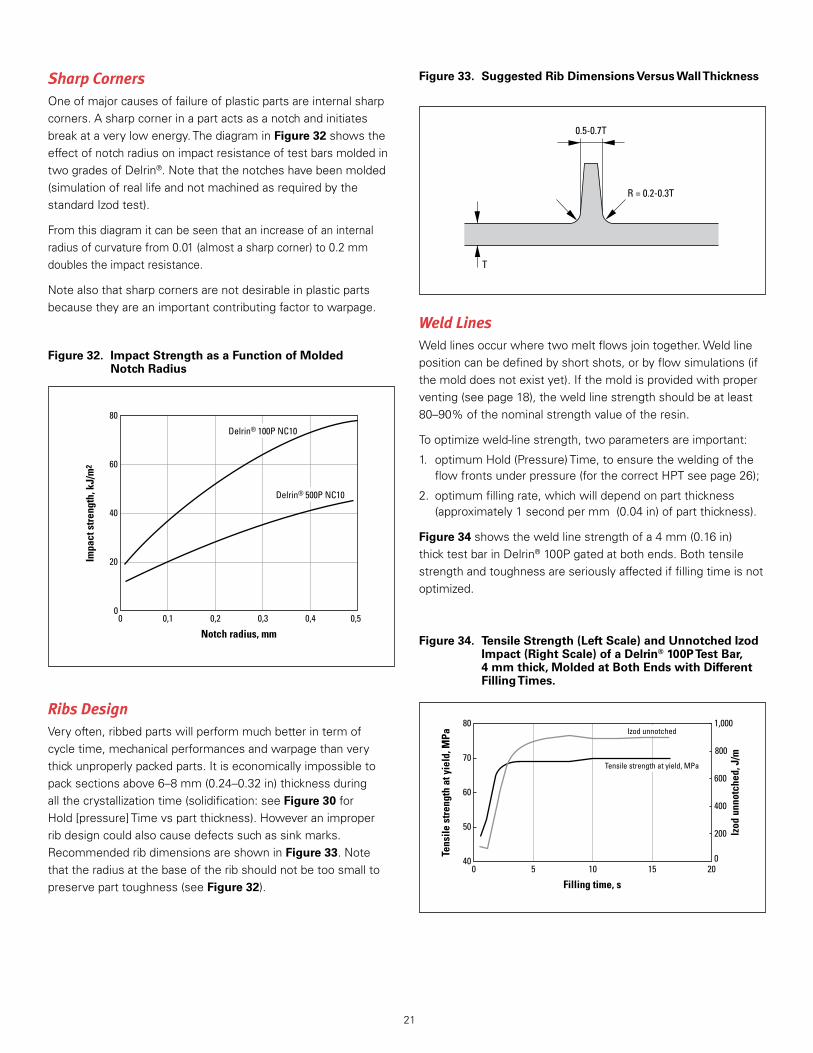
Sharp CornersOneofmajorcausesoffailureofplasticpartsareinternalsharpcorners .Asharpcornerinapartactsasanotchandinitiatesbreakataverylowenergy .ThediagraminFigure 32showstheeffectofnotchradiusonimpactresistanceoftestbarsmoldedintwogradesofDelrin® .Notethatthenotcheshavebeenmolded(simulationofreallifeandnotmachinedasrequiredbythestandardIzodtest) .
Fromthisdiagramitcanbeseenthatanincreaseofaninternalradiusofcurvaturefrom0 .01(almostasharpcorner)to0 .2mmdoublestheimpactresistance .
Notealsothatsharpcornersarenotdesirableinplasticpartsbecausetheyareanimportantcontributingfactortowarpage .
Ribs DesignVeryoften,ribbedpartswillperformmuchbetterintermofcycletime,mechanicalperformancesandwarpagethanverythickunproperlypackedparts .Itiseconomicallyimpossibletopacksectionsabove6–8mm(0 .24–0 .32in)thicknessduringallthecrystallizationtime(solidification:seeFigure 30forHold[pressure]Timevspartthickness) .Howeveranimproperribdesigncouldalsocausedefectssuchassinkmarks .RecommendedribdimensionsareshowninFigure 33 .Notethattheradiusatthebaseoftheribshouldnotbetoosmalltopreserveparttoughness(seeFigure 32) .
Weld LinesWeldlinesoccurwheretwomeltflowsjointogether .Weldlinepositioncanbedefinedbyshortshots,orbyflowsimulations(ifthemolddoesnotexistyet) .Ifthemoldisprovidedwithproperventing(seepage18),theweldlinestrengthshouldbeatleast80–90%ofthenominalstrengthvalueoftheresin .
Tooptimizeweld-linestrength,twoparametersareimportant:
1 . optimumHold(Pressure)Time,toensuretheweldingoftheflowfrontsunderpressure(forthecorrectHPTseepage26);
2 . optimumfillingrate,whichwilldependonpartthickness(approximately1secondpermm(0 .04in)ofpartthickness) .
Figure 34showstheweldlinestrengthofa4mm(0 .16in)thicktestbarinDelrin®100Pgatedatbothends .Bothtensilestrengthandtoughnessareseriouslyaffectediffillingtimeisnotoptimized .
22
Mold MaintenanceAsageneralrule,moldsforprocessingDelrin®requirethesamecareasthoseforprocessingotherthermoplasticmaterials .Wipingthemoldandapplyingarust-preventingsolutionisusuallyadequateafteraproductionrun .
Vent Maintenance
Duetothecriticalnatureofthevents,theventdimensionsshouldbecheckedduringroutinemaintenance .Ventdepthand/orhobbing(deformationofthepartinglineoppositethevent)shouldbecarefullychecked .Ventsshouldbemodifiediftheventdepthislessthan0 .01mmto0 .015mm .Anyhobbingthatblockstheventsshouldbegroundoff .
Mold CleaningDependingonthetypeofdepositthecleaningprocedureisasfollows:
• White depositWhitedepositisduetotheaccumulationofparaformaldehyde .Thisdepositcanberemovedwithbenzylalcoholorisopropanol .Frequentcleaningofthetoolwiththesesolventsduringmoldingwillpreventtheaccumulationofthisdeposit .
• Translucent or colored depositThisdepositisnormallyobservednearthegate(incaseofovershearofthematerial),onpinsornearhotspots .Theuseofalessshearinggate(seegatedesignrecommendations)oramoreevenmoldtemperaturewillstoportremendouslydecreasethebuildupofthisdeposit .Itcanberemovedwithcommercialalkalinechemicalcleaners .Efficiencyofthecleaningagentcanbeimprovedwithanultrasonicbath .
23
Molding Process
InjectionmoldingofDelrin®acetalresinissimilartothatofotherthermoplasticresins .TheengineeringapplicationsforwhichDelrin®isused,however,frequentlyrequiretightspecificationsonstrength,dimensionsandsurfacecondition,sothatcontrolofthemoldingoperationbecomesmorecritical .
Theinformationdiscussedinthissectionincludessuggestionsfor:
• Start-upandshutdownprocedures,handlingprecautions
• OperatingconditionsforDelrin®
• Techniquesforoptimumproductivitymolding
Start-up and Shutdown ProceduresStart-up with Resin Change
Thesuggestedstart-upprocedurewithDelrin®isdesignedtopreventoverheatingoftheresinandcontaminationintheinjectionunitwithmaterialfrompreviousruns .
Tostartupamachinewhichcontainsanotherresin,theinjectionunitmustbepurgedwithcrystalpolystyreneuntilthecylinderandotherhightemperaturezoneshavebeencleared .Thiscannormallybedonewithcylindertemperaturesintherange210–250°C(410–482°F),ifappropriateforthepreviousmaterial .Thenozzleisquitedifficulttocleanbypurging,becausethelaminarflowinthisarealeadstoalayerofpolymerstickingtothemetal(thisisalsotrueforhotrunners) .Itisthereforerecommendedtoswitchoffthenozzleheater,removethenozzle,cleanittogetridalltracesofpreviouspolymer,andreassembleit .Thecylindertemperaturesshouldthenbeadjustedtoabout215°C(419°F),andthenozzletemperatureto190°C(374°F) .Whenbothcylinderandnozzlehavereachedtheexpectedtemperatures,Delrin®canbeaddedtothehopper .
Inunusualcircumstances,anintermediatepurgewithaharshercompoundmayberequiredtoremoveadherentdepositsfromthescrewandcylinder .Specialpurgecompoundsareusedforthispurpose .
ThesepurgecompoundsmustalsoberemovedfromthecylinderbypurgingwithpolyethyleneorpolystyrenebeforeDelrin®isintroduced .Intheworstcases,e .g .,afteruseofglass-reinforcedresinsorseveredegradationofpreviousmaterial,itmaybenecessarytopullthescrewandcleantheequipmentmanuallytopreventcontaminationofmoldings .
Safety point:PolystyreneischemicallycompatiblewithDelrin®,whereasevenatraceofpolyvinylchloride(PVC)isnot .ContaminationofDelrin®withsuchmaterialcancauseobjectionableodororevenaviolentblowback .
Start-Up From a Cylinder Containing Delrin®
Afterasafeshut-downprocedure,thescrewandthecylindershouldbeessentiallyempty .Torestart,thenozzleandcylindertemperaturesshouldbesetat190°C(374°F)topreheatthecylinderandtheresinitcontains .Whenthecylinderhasreachedthesettemperature,ensurethatthenozzleisopenandincreasethecylindersettingstonormaloperatingtemperatures .Whenalltemperaturesareintheoperatingrange,thehoppercanbefilledandmoldingcanbeginafterabriefpurgewithDelrin® .
Shutdown When a Restart with Delrin® is Planned
Shutoffthehopperfeedandcontinuemoldinguntilthecylinderisempty .Forlargemachines(withascrewdiameterabove40mm[1 .57in])itisrecommendedtopurgethecylinderwithcrystalpolystyrene,movethescrewfullyforward,thenswitchofftheheaterbands .Forsmallmachinesmovethescrewfullyforwardandswitchofftheheaterbands .
Shutdown When a Restart with Another Resin is Planned
Shutoffthehopperfeedandcontinuemoldinguntilthecylinderisempty .Purgewithcrystalpolystyrene,leavethescrewfullyforward,thenswitchofftheheaterbands .
Temporary Interruption
AmoldingmachinewithDelrin®inthecylinderatmoldingtemperaturesshouldnotbeallowedtostayidle .Themaximumrecommendedcylinderresidencetime,undernormalmoldingconditions,is10minforpigmentedmaterialand20minfornaturalstandardmaterial .Inexcessofthesetimes,resindecompositionmayoccur .
If,duringthetemporaryinterruption,thecylinderresidencetimereachestheabovelimits,closethehopperfeed,emptythecylinderandleavethescrewforward .Thecylindertemperaturesshouldbereducedtoabout150°C(302°F)(atthesetemperaturesDelrin®willbestableevenforaweekendshutdown) .
Action to Follow When the Nozzle Heater Band Breaks Down
Retracttheinjectionunit,closethehopperandslideitoutoftheway .Ifthenozzleisstillopen,followthenormalshutdownprocedures .Ifthenozzleisfrozen,heatthenozzlewithagastorchtomeltthefrozenmaterialinsidethenozzleandthenpurge .
Start-up after Emergency Shutdown
Adifferentprocedureshouldbeusedafteranemergencyshutdownduetolossofpowerorothercauses .Inthiscase,thescrewmaybefullofDelrin®thatcooledslowlyandwasexposedtomelttemperaturesforaprolongedperiod .ThescrewmayevenbeintheretractedpositionwithalargequantityofDelrin®infrontofthescrew .Inordertoventgasesfromresinthatmaybedegraded,itisessentialthatthenozzlebeopenandheatedtooperatingtemperatureandDelrin®inthisareabecompletelymeltedbeforethecylinderreachesmelttemperature .Thecylinderzonesshouldbeheatedtoanintermediatetemperature
24
belowthemeltingpointofDelrin®andthemachineallowedtoequilibrateatthattemperature .Cylindertemperaturesof150–175°C(300–350°F)aresuggested .Afterallzoneshavebeenatthistemperaturefor30min,cylindertemperaturesshouldberaisedto195°C(380°F) .AssoonastheDelrin®hasmelted,itshouldbepurgedfromthecylinderwithfreshDelrin® .Thepartlydegraded,hotpurgeresinshouldbeplacedinapailofwaterifitemitsanodor .Whentheoldresinispurgedfromthecylinder,thecylindertemperaturesmayberaisedtonormalproductionsettings .
Operating Conditions for Delrin® — Temperature SettingsIntroduction
Thebasicpurposeoftheinjectionunitistodelivertothemoldthenecessaryamountofahomogeneousmelt(nounmeltandnodegradedmaterial) .Therulesofconstructionoftheinjectionunitformoldingacrystallinematerialhavebeenpresentedin“InjectionMoldingUnit,”(seepage7);therulesforthesettingsarepresentedbelow .
Note:Tworoughbutpracticalmethodstoevaluatethepresenceofunmeltandofdegradedmaterialweredescribedonpage11andcanbeusedhereaswell .
Delrin®acetalresinisacrystallinepolymerwithameltingpointof178°C(352°F) .FormostgradesofDelrin®homopolymerthepreferredmelttemperaturerangeis215°C(419°F)±5°C*,asmeasuredwithaneedlepyrometerinthemelt .ThecaloriesneededtoheatandmeltDelrin®willbeprovidedbyshear(fromscewrotation)andthebalancebyconductionintheheatedcylinder(slowheattransferduetotheinsulatingcharacterofpolymers) .
Cylinder temperature
Themainparameterinfluencingthetemperatureprofileofthecylinderistheresidencetime(orHold-UpTime—HUT)ofthepolymerintheplastificationunit(seepage8tocalculateHUT) .
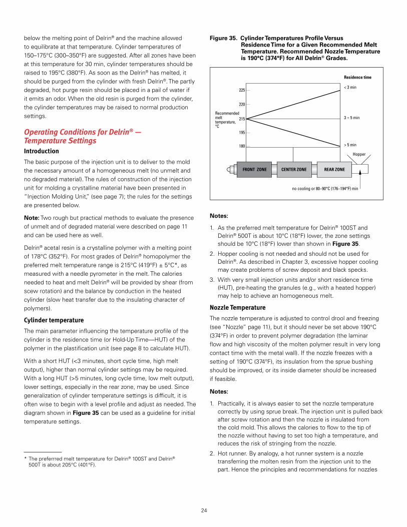
WithashortHUT(<3minutes,shortcycletime,highmeltoutput),higherthannormalcylindersettingsmayberequired .WithalongHUT(>5minutes,longcycletime,lowmeltoutput),lowersettings,especiallyintherearzone,maybeused .Sincegeneralizationofcylindertemperaturesettingsisdifficult,itisoftenwisetobeginwithalevelprofileandadjustasneeded .ThediagramshowninFigure 35canbeusedasaguidelineforinitialtemperaturesettings .
Notes:
1 . AsthepreferredmelttemperatureforDelrin®100STandDelrin®500Tisabout10°C(18°F)lower,thezonesettingsshouldbe10°C(18°F)lowerthanshowninFigure 35 .
2 . HoppercoolingisnotneededandshouldnotbeusedforDelrin® .AsdescribedinChapter3,excessivehoppercoolingmaycreateproblemsofscrewdepositandblackspecks .
3 . Withverysmallinjectionunitsand/orshortresidencetime(HUT),pre-heatingthegranules(e .g .,withaheatedhopper)mayhelptoachieveanhomogeneousmelt .
Nozzle Temperature
Thenozzletemperatureisadjustedtocontroldroolandfreezing(see“Nozzle”page11),butitshouldneverbesetabove190°C(374°F)inordertopreventpolymerdegradation(thelaminarflowandhighviscosityofthemoltenpolymerresultinverylongcontacttimewiththemetalwall) .Ifthenozzlefreezeswithasettingof190°C(374°F),itsinsulationfromthespruebushingshouldbeimproved,oritsinsidediametershouldbeincreasediffeasible .
Notes:
1 . Practically,itisalwayseasiertosetthenozzletemperaturecorrectlybyusingspruebreak .Theinjectionunitispulledbackafterscrewrotationandthenthenozzleisinsulatedfromthecoldmold .Thisallowsthecaloriestoflowtothetipofthenozzlewithouthavingtosettoohighatemperature,andreducestheriskofstringingfromthenozzle .
2 . Hotrunner .Byanalogy,ahotrunnersystemisanozzletransferringthemoltenresinfromtheinjectionunittothepart .Hencetheprinciplesandrecommendationsfornozzles
*ThepreferrredmelttemperatureforDelrin®100STandDelrin® 500Tisabout205°C(401°F) .
Figure 35. Cylinder Temperatures Profile Versus Residence Time for a Given Recommended Melt Temperature. Recommended Nozzle Temperature is 190°C (374°F) for All Delrin® Grades.
Residence time
215
220
225
195
180
FRONT ZONE CENTER ZONE REAR ZONE
< 3 min
> 5 min
Hopper
no cooling or 80–90°C (176–194°F) min
3 5 minRecommendedmelttemperature,°C

25
arealsovalidforhotrunners .Inparticular,thelaminarflowandhighviscosityofthemoltenpolymeragainresultinverylongcontacttimeswiththemetalwall;sothetemperatureofthemetalinthehotrunnershouldneverexceed190°C(374°F),inordertopreventdegradationofthepolymer .
Screw Rotation Speed
Screwrotationspeedbehavesasa“thermalsetting,”becausetherotationofthescrewwill“shear”thematerialandsupplyaroundhalfofthecaloriesneededtomeltandheatDelrin®totherecommendedmelttemperaturerangeof215°C(419°F)±5°C(205°C[401°F]±5°CforDelrin®TandST) .Aswithallpolymers,Delrin®issensitivetoshearandamaximumof0 .2to0 .3m/sofscrewperipheralspeedisrecommended .Figure 36showstheoptimumscrewrotationspeedforhighviscosityDelrin®(type100)andlowviscosityDelrin®(types500to900)asafunctionofscrewdiameter .
Back Pressure
Backpressurealsobehaveslikeathermalsetting .Increasingbackpressureincreasestheworkdonebythescrewonthemelt .
Theuseoftheoptimumscrewdesignforcrystallinematerials,suchasDelrin®,shouldprovidethenecessaryworktomeltandbringDelrin®totherecommendedmelttemperaturewiththeminimumbackpressure .OnlymeltingofhighlyviscousDelrin®suchasDelrin®100Pmayrequiresomebackpressuretoavoidthescrewwormingback(leadingtoinconsistentshotvolumeandpad) .
Figure 36. Maximum Screw Rotation Speed as Function of Screw Diameter. The Curve for Delrin® 500P is Also Valid for the Low Viscosity Grades Delrin® 900.
Screw diameter, mm
Max
. scr
ew ro
tatio
n sp
eed,
rpm
80 1006040200
50
100
150
200
250
300
0
Delrin® 500PDelrin® 100P
Theuseofaninappropriatescrewmayrequiresomebackpressuretoincreasetheworkdonebythescrewonthemelt,toincreasethemelttemperatureanditsuniformity .Higherbackpressuremaybeusedtoeliminateunmeltedparticlesandtoimprovecolormixingwhencolorconcentratesareused .Increasingbackpressure,however,tendstoreduceglassfibrelengthandchangepropertiesoffilledresinssuchasDelrin®570 .Moreimportantly,increasingbackpressurealwaysdecreasestheoutputofthescrew,leadingtolongercycletimesandlowerproductivity .Thisincreasesthebuildupofscrewdepositleadingtocontaminationandlowpartperformance .
Therefore,backpressureshouldbeusedonlywhenincreasingcylindertemperatureorotherchangesarenoteffectiveorpossible .
Forallmaterials,thebackpressureused(specificorinherenttotheinjectionunit)willcreatesomepressureonthemeltinfrontofthescrew .Tocontroldroolattheendofthescrewrotation,somesuckbackisrequired .Thisshouldbekepttoaminimum .
Mold Temperature
ThebestmoldtemperatureforlongtermpartperformancewouldbejustbelowthecrystallizationtemperatureofDelrin®,e .g .,155°C(311°F) .Thistemperaturewouldallowthepolymertocrystallizeinanoptimumstateandeliminateanyriskofre-crystallization(postmoldingshrinkage) .Obviouslyitiseconomicallyimpossibletosetthemoldatthattemperatureasthecrystallizationtimebecomesalmostinfinitealongwiththecycletime .
Practically,alowermoldtemperatureisused,leadingtoshortercrystallizationtime(HPT),henceshortercycletime,lowermoldshrinkagebuthigherpostmoldshrinkage(especiallyifpartsarethenexposedtoelevatedtemperatures) .Acompromiseshouldbefounddependingonthetemperatureinuseandtherequireddimensionalprecisionofthemoldedpartshortandlongterm .
ForstandardDelrin®,amoldtemperatureof80–100°C(176–212°F)isagoodcompromisefornormaluse,givingrelativelyshortcrystallizationtime,highshrinkagebutlowpostmoldshrinkage(see“DimensionalConsiderations,”page31) .Ahighermoldtemperaturewillleadtohighermoldshrinkage,longercycletimebutlowerpostmoldshrinkage .Itisspeciallyrecommendedforhighprecisionpartsusedathightemperature .Alowermoldtemperatureleadstoshortercycletime,lowermoldshrinkagebutmuchhigherpostmoldshrinkageleadingtostressesanddistortion .
FortoughenedresinssuchasDelrin®100STand500T,theuseofalowermoldtemperature(50°C[122°F]±10°C[50°F])isacceptablewithoutendangeringlongtermpartperformances .
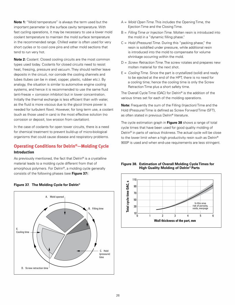
26
Note 1:“Moldtemperature”isalwaysthetermusedbuttheimportantparameteristhesurfacecavitytemperature .Withfastcyclingoperations,itmaybenecessarytousealowermoldcoolanttemperaturetomaintainthemoldsurfacetemperatureintherecommendedrange .Chilledwaterisoftenusedforveryshortcyclesortocoolcorepinsandothermoldsectionsthattendtorunveryhot .
Note 2:Coolant:Closedcoolingcircuitsarethemostcommontypesusedtoday .Coolantsforclosedcircuitsneedtoresistheat,freezing,pressureandvacuum .Theyshouldneitherleavedepositsinthecircuit,norcorrodethecoolingchannelsandtubes(tubescanbeinsteel,copper,plastic,rubberetc .) .Byanalogy,thesituationissimilartoautomotiveenginecoolingsystems,andhenceitisrecommendedtousethesamefluid(anti-freeze+corrosioninhibitor)butinlowerconcentration .Initiallythethermalexchangeislessefficientthanwithwater,asthefluidismoreviscousduetotheglycol(morepowerisneededforturbulentflow) .However,forlongtermuse,acoolant(suchasthoseusedincars)isthemosteffectivesolution(nocorrosionordeposit,lowerosionfromcavitation) .
Inthecaseofcoolantsforopentowercircuits,thereisaneedforchemicaltreatmenttopreventbuild-upofmicro-biologicalorganismsthatcouldcausediseaseandrespiratoryproblems .
Operating Conditions for Delrin®—Molding CycleIntroduction
Aspreviouslymentioned,thefactthatDelrin®isacrystallinematerialleadstoamoldingcycledifferentfromthatofamorphouspolymers .ForDelrin®,amoldingcyclegenerallyconsistsofthefollowingphases(seeFigure 37):
A=Mold Open Time .ThisincludestheOpeningTime,theEjectionTimeandtheClosingTime .
B=Filling Time or Injection Time .Moltenresinisintroducedintothemoldina“dynamicfillingphase .”
C=Hold (Pressure) Time .Duringthis“packingphase,”theresinissolidifiedunderpressure,whileadditionalresinisintroducedintothemoldtocompensateforvolumeshrinkageoccurringwithinthemold .
D=Screw Retraction Time .Thescrewrotatesandpreparesnewmoltenmaterialforthenextshot .
E= Cooling Time .Sincethepartiscrystallized(solid)andreadytobeejectedattheendoftheHPT,thereisnoneedforacoolingtime;hencethecoolingtimeisonlytheScrewRetractionTimeplusashortsafetytime .
TheOverallCycleTime(OAC)forDelrin®istheadditionofthevarioustimessetforeachofthemoldingoperations .
Note:FrequentlythesumoftheFilling(Injection)TimeandtheHold(Pressure)TimeisdefinedasScrewForwardTime(SFT),asoftenstatedinpreviousDelrin®literature .
ThecycleestimationgraphinFigure 38showsarangeoftotalcycletimesthathavebeenusedforgoodqualitymoldingofDelrin®inpartsofvariousthickness .TheactualcyclewillbeclosetothelowerlimitwhenahighproductivityresinsuchasDelrin®900Pisusedandwhenend-userequirementsarelessstringent .
B. Filling time
E.Cooling time
C. Hold (pressure)time
A. Mold opened
D. Screw retraction time
Figure 37. The Molding Cycle for Delrin®
Figure 38. Estimation of Overall Molding Cycle Times for High Quality Molding of Delrin® Parts
Wall thickness of the part, mm
Tota
l cyc
le ti
me
OA
C, s
3 4 5 61 20
30
50
70
90
110
10
In this arearisk of porosity,voids, warpage
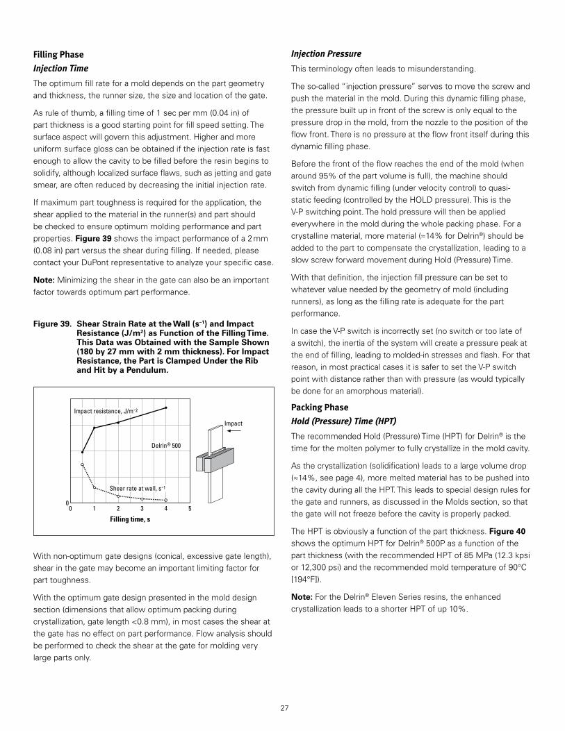
27
Filling Phase
Injection Time
Theoptimumfillrateforamolddependsonthepartgeometryandthickness,therunnersize,thesizeandlocationofthegate .
Asruleofthumb,afillingtimeof1secpermm(0 .04in)ofpartthicknessisagoodstartingpointforfillspeedsetting .Thesurfaceaspectwillgovernthisadjustment .Higherandmoreuniformsurfaceglosscanbeobtainediftheinjectionrateisfastenoughtoallowthecavitytobefilledbeforetheresinbeginstosolidify,althoughlocalizedsurfaceflaws,suchasjettingandgatesmear,areoftenreducedbydecreasingtheinitialinjectionrate .
Ifmaximumparttoughnessisrequiredfortheapplication,theshearappliedtothematerialintherunner(s)andpartshouldbecheckedtoensureoptimummoldingperformanceandpartproperties .Figure 39showstheimpactperformanceofa2mm(0 .08in)partversustheshearduringfilling .Ifneeded,pleasecontactyourDuPontrepresentativetoanalyzeyourspecificcase .
Note:Minimizingtheshearinthegatecanalsobeanimportantfactortowardsoptimumpartperformance .
Withnon-optimumgatedesigns(conical,excessivegatelength),shearinthegatemaybecomeanimportantlimitingfactorforparttoughness .
Withtheoptimumgatedesignpresentedinthemolddesignsection(dimensionsthatallowoptimumpackingduringcrystallization,gatelength<0 .8mm),inmostcasestheshearatthegatehasnoeffectonpartperformance .Flowanalysisshouldbeperformedtochecktheshearatthegateformoldingverylargepartsonly .
Filling time, s3 4 5210
0
Impact resistance, J/m-2
Shear rate at wall, s-1
Impact
Delrin® 500
Figure 39. Shear Strain Rate at the Wall (s–1) and Impact Resistance (J/m2) as Function of the Filling Time. This Data was Obtained with the Sample Shown (180 by 27 mm with 2 mm thickness). For Impact Resistance, the Part is Clamped Under the Rib and Hit by a Pendulum.
Injection Pressure
Thisterminologyoftenleadstomisunderstanding .
Theso-called“injectionpressure”servestomovethescrewandpushthematerialinthemold .Duringthisdynamicfillingphase,thepressurebuiltupinfrontofthescrewisonlyequaltothepressuredropinthemold,fromthenozzletothepositionoftheflowfront .Thereisnopressureattheflowfrontitselfduringthisdynamicfillingphase .
Beforethefrontoftheflowreachestheendofthemold(whenaround95%ofthepartvolumeisfull),themachineshouldswitchfromdynamicfilling(undervelocitycontrol)toquasi-staticfeeding(controlledbytheHOLDpressure) .ThisistheV-Pswitchingpoint .Theholdpressurewillthenbeappliedeverywhereinthemoldduringthewholepackingphase .Foracrystallinematerial,morematerial(≈14%forDelrin®)shouldbeaddedtotheparttocompensatethecrystallization,leadingtoaslowscrewforwardmovementduringHold(Pressure)Time .
Withthatdefinition,theinjectionfillpressurecanbesettowhatevervalueneededbythegeometryofmold(includingrunners),aslongasthefillingrateisadequateforthepartperformance .
IncasetheV-Pswitchisincorrectlyset(noswitchortoolateofaswitch),theinertiaofthesystemwillcreateapressurepeakattheendoffilling,leadingtomolded-instressesandflash .Forthatreason,inmostpracticalcasesitissafertosettheV-Pswitchpointwithdistanceratherthanwithpressure(aswouldtypicallybedoneforanamorphousmaterial) .
Packing Phase
Hold (Pressure) Time (HPT)
TherecommendedHold(Pressure)Time(HPT)forDelrin®isthetimeforthemoltenpolymertofullycrystallizeinthemoldcavity .
Asthecrystallization(solidification)leadstoalargevolumedrop(≈14%,seepage4),moremeltedmaterialhastobepushedintothecavityduringalltheHPT .Thisleadstospecialdesignrulesforthegateandrunners,asdiscussedintheMoldssection,sothatthegatewillnotfreezebeforethecavityisproperlypacked .
TheHPTisobviouslyafunctionofthepartthickness .Figure 40showstheoptimumHPTforDelrin®500Pasafunctionofthepartthickness(withtherecommendedHPTof85MPa(12 .3kpsior12,300psi)andtherecommendedmoldtemperatureof90°C[194°F]) .
Note:FortheDelrin®ElevenSeriesresins,theenhancedcrystallizationleadstoashorterHPTofup10% .
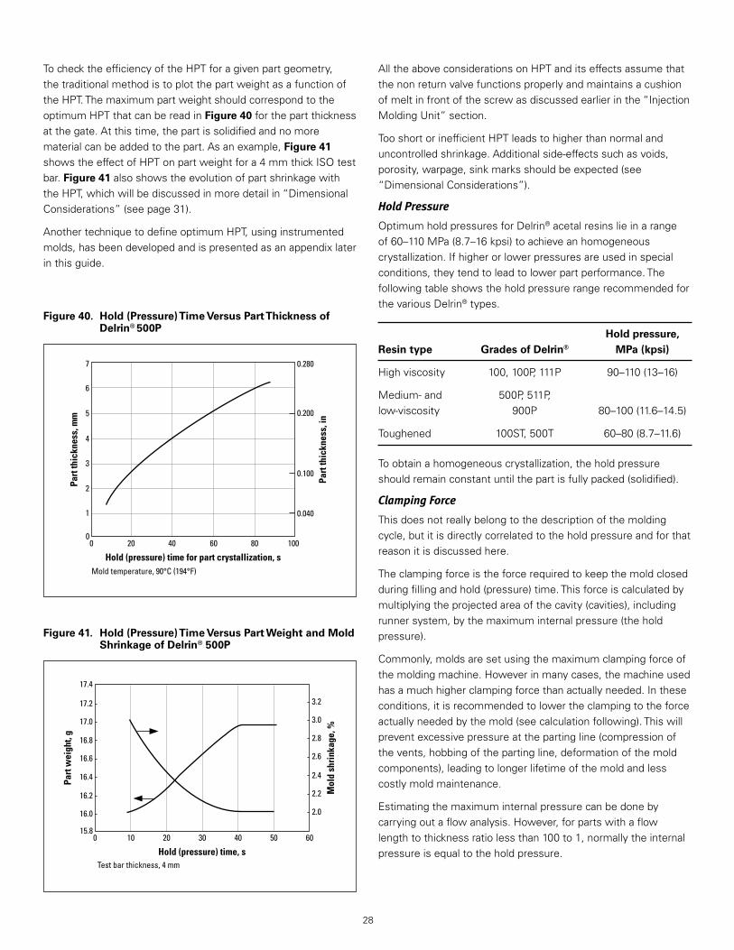
28
TochecktheefficiencyoftheHPTforagivenpartgeometry,thetraditionalmethodistoplotthepartweightasafunctionoftheHPT .ThemaximumpartweightshouldcorrespondtotheoptimumHPTthatcanbereadinFigure 40forthepartthicknessatthegate .Atthistime,thepartissolidifiedandnomorematerialcanbeaddedtothepart .Asanexample,Figure 41showstheeffectofHPTonpartweightfora4mmthickISOtestbar .Figure 41alsoshowstheevolutionofpartshrinkagewiththeHPT,whichwillbediscussedinmoredetailin“DimensionalConsiderations”(seepage31) .
AnothertechniquetodefineoptimumHPT,usinginstrumentedmolds,hasbeendevelopedandispresentedasanappendixlaterinthisguide .
AlltheaboveconsiderationsonHPTanditseffectsassumethatthenonreturnvalvefunctionsproperlyandmaintainsacushionofmeltinfrontofthescrewasdiscussedearlierinthe“InjectionMoldingUnit”section .
TooshortorinefficientHPTleadstohigherthannormalanduncontrolledshrinkage .Additionalside-effectssuchasvoids,porosity,warpage,sinkmarksshouldbeexpected(see“DimensionalConsiderations”) .
Hold Pressure
OptimumholdpressuresforDelrin®acetalresinslieinarangeof60–110MPa(8 .7–16kpsi)toachieveanhomogeneouscrystallization .Ifhigherorlowerpressuresareusedinspecialconditions,theytendtoleadtolowerpartperformance .ThefollowingtableshowstheholdpressurerangerecommendedforthevariousDelrin®types .
Hold pressure, Resin type Grades of Delrin® MPa (kpsi)
Highviscosity 100,100P,111P 90–110(13–16)
Medium-and 500P,511P,low-viscosity 900P 80–100(11 .6–14 .5)
Toughened 100ST,500T 60–80(8 .7–11 .6)
Toobtainahomogeneouscrystallization,theholdpressureshouldremainconstantuntilthepartisfullypacked(solidified) .
Clamping Force
Thisdoesnotreallybelongtothedescriptionofthemoldingcycle,butitisdirectlycorrelatedtotheholdpressureandforthatreasonitisdiscussedhere .
Theclampingforceistheforcerequiredtokeepthemoldclosedduringfillingandhold(pressure)time .Thisforceiscalculatedbymultiplyingtheprojectedareaofthecavity(cavities),includingrunnersystem,bythemaximuminternalpressure(theholdpressure) .
Commonly,moldsaresetusingthemaximumclampingforceofthemoldingmachine .Howeverinmanycases,themachineusedhasamuchhigherclampingforcethanactuallyneeded .Intheseconditions,itisrecommendedtolowertheclampingtotheforceactuallyneededbythemold(seecalculationfollowing) .Thiswillpreventexcessivepressureatthepartingline(compressionofthevents,hobbingofthepartingline,deformationofthemoldcomponents),leadingtolongerlifetimeofthemoldandlesscostlymoldmaintenance .
Estimatingthemaximuminternalpressurecanbedonebycarryingoutaflowanalysis .However,forpartswithaflowlengthtothicknessratiolessthan100to1,normallytheinternalpressureisequaltotheholdpressure .
Figure 40. Hold (Pressure) Time Versus Part Thickness of Delrin® 500P
Figure 41. Hold (Pressure) Time Versus Part Weight and Mold Shrinkage of Delrin® 500P
Hold (pressure) time for part crystallization, s
Part
thic
knes
s, m
m
Part
thic
knes
s, in
10060 8040200
Mold temperature, 90°C (194°F)
1
2
3
4
5
6
7
0
0.280
0.200
0.100
0.040
Hold (pressure) time, s
Part
wei
ght,
g
Mol
d sh
rink
age,
%
40 50 6020 30100
17.2
17.4
17.0
16.8
16.6
Test bar thickness, 4 mm
16.4
16.2
16.0
3.2
3.0
2.8
2.6
2.4
2.2
2.0
15.8

29
Thefollowingguidelinescanbeused:
1 . Forpartsneedingoptimummechanicalproperties,thespecificclampingpressuremustbe1ton/cm2forDelrin®100P,and0 .85ton/cm2forotherDelrin®grades .
Examplecalculation:
• projectedareaofpart(orparts),includingrunnersystem=115cm2
• material=Delrin®500
• machineclampingforcerequired=115×0 .85=98tons
2 . Forpartsnotrequiringoptimummechanicalproperties,itmaybepossibletomoldacceptablepartswithlowerspecificholdpressures(andlowerclampingforces) .
Plastification Phase
Screw Retraction Time
Givenafixedamountofresintoplasticizeforthenextshot,thescrewretractiontimeisdirectlydependentonthescrewrotationspeed .
Itiscrucialtocheckthattheappliedscrewrotationspeedislowenoughtoavoidover-shearingtheresininthebarrel(whichmayleadtodegradation),buthighenoughtoprovideahomogeneousmelt(withnounmeltedparticles) .Thiscanbedonewiththetwopracticaltestsforthepresenceofunmeltanddegradedmaterial,asdescribedonpage11 .
Note:sinceDelrin®isahighlycrystallinepolymer,itsthermalrequirementsaredifferentfromthoseofamorphousmaterials .ScrewsspecificallydesignedforDelrin®andanappropriateratioofshotweighttomachinecapacityprovideanefficientplastification .Formoredetailsaboutscrewdimensions,seepages8–9 .
Cooling Time
Thecoolingtimeisanimportantparameterfortheinjectionmoldingofamorphouspolymers .ThesituationiscompletelydifferentwithDelrin®(seealsopages5–6) .Attheendofacorrectlysetandefficientholdpressuretime(HPT),theDelrin®partiscrystallizedandsolid .Thereisnoneedforfurthercoolingtime,andthepartcouldinprinciplebeejectedimmediatelyfromthemold .ThiscanbedemonstratedbystoppingthecycleattheendoftheHPTandejectingthepartimmediately .
Inmostpracticalcasesthepartisejectedafterthescrewretractiontime,sothecoolingtime(asdefinedinFigure 37)issimplythescrewretractiontimeplusasmallsafetymargin .Anexceptionisthecaseofmachineswithshut-offnozzles,wherepartejectioncantakeplaceduringthescrewrotation .Thistheoreticallygivesshortercycles,althoughpracticalproblemsmayariseandlimitproductivity(seepage11formoredetailsonshut-offnozzles) .
Optimum Productivity MoldingEconomicconstraintsarepushingforlowerpartcost,whichcanbereachedbyincreasingtheyieldofqualitypartsand/orshorteningtheOverAllCycletime .Thisguiderecommendstheparameterstoachieveoptimumpartpropertiesintheshortandinthelongterm,leadingtoanoptimumOverAllCycletime(OAC) .
Anymodificationtothecycleshouldbedoneonlyafterrealisticevaluationofpartperformanceshortandlongterm .Decreasingthecycletoomuchmayleadtoa)lowerpartpropertiesandotherqualityproblems(especiallyshrinkage,warpageandpostshrinkage),andb)processnotrunninginarobustarea,whichcouldleadtoloweryieldofqualitypartsandhigherpartcost .
BeforetryingtoshortenthecurrentOAC,thefollowingitemsshouldbeconsidered:
• Thedesignofthepartmaynotbeoptimum,i .e .,thepartmaybetoothick .Changestothedesign(addingribs,useofpins)arecostlybutmayallowsignificantreductionofthecycletime .
• Thedesignofinjectionunitmaynotbeoptimum .WithDelrin®thecoolingtimecanbeminimizedtothetimerequiredforproperscrewretraction .Optimumscrewsizeanddesignwillfacilitatethis .
• Thesortingofpartsfromrunnersmaynotbeoptimized .
HavingdecidedtodecreasetheOAC,thefollowingactionsmaybecarriedout(inorderofincreasingrisk):
• Investigateobviousbottlenecksinthecycle .
• MinimizetheMoldOpenstroke .
• MinimizetheMoldOpentimebyincreasingtheopening/closingspeeds .Rubberbumpersorspringscanbeusedtopreventbangingofthefloatingplatein3platemolds,givingnoeffectonpartquality .
• Minimizetimebetweenthescrewstoppingandthemoldopening .Noeffectonpartquality .
• MinimizeFillingTime(fasterinjectionfill) .Itmayresultinovershearinganddecreasedweldlinestrength .Largernozzleandrunners,aswellasimprovedventingmayberequired .
• DecreaseScrewRetractionTime:
1 . Usealargerscrewandlimitthestroketobetween1and2screwdiameters,noeffectonpartquality .
2 . UseanoptimizedscrewdesignforDelrin®(screwforcrystallinepolymerswithcorrectdepthofmeteringzone,mixinghead) .Thisensuresahomogeneousmeltevenathighscrewrotationspeeds,hencetherearenoeffectsonpartquality .UsinghigherscrewrotationspeedswithageneralpurposescrewwouldreduceSRT,butwiththeriskofpoormeltqualityandpartfailure .
Note:asthereisnoneedforcoolingtime,shutoffnozzles(wherethescrewcanberotatedduringmoldopening)havebeentried .Unfortunately,problemssuchaswear,contamination,holdupspotsetc .havebeenobserved,andnolong-termsatisfactorysolutionwasfound .

30
• DecreaseHold(Pressure)Time .WithalowerthanoptimumHPT,highermoldshrinkageanddeformationleadingtowarpagewillbeseen .Voidswillalsobeformedinthecenterofthepart,leadingtolowermechanicalproperties(lowerelongationatbreak),andqualitycontrolshouldbecarriedoutonlargerlotsofmoldedparts .IfthemoldtemperatureisdecreasedasanattempttocompensatefortheshorterHPT,thisactionwillleadtoalowermoldshrinkagebutwillresultinveryhighpostmoldingshrinkage,deformationandwarpage .
Standard Molding Conditions for ISO Tensile BarsStandardprocessingparameterstoinjectionmoldDelrin®intotensilebarsISO294-1areshowninTable 5 .TheycanhelpmoldersinestablishingmoldingparameterswhenprocessingDelrin®acetalresins .However,itmustbeemphasizedthatforpartsofdifferentshapesanddimensionssuchparametersshouldbemodifiedusingtheinformationpresentedonpages29–34 .
Hold Pressure Time via In-cavity Pressure MeasurementThistechniquehasbeendevelopedduringrecentyears,particularlyforamorphousresins .Themainobjectivewastooptimizeandcontroltheholdpressureprofileinordertoreduceinternalstresses,whichhavebeenafrequentcauseoffailureofmoldedarticlesinamorphouspolymers .
EvenifsuchproblemsofinternalstressesdonotapplytoacrystallinepolymerlikeDelrin®,thistechniqueisprovingtobeaneffectivemethodtodeterminethecrystallizationtime(HPT)ofapartmoldedwithaspecificpolymergradeatgivenprocessingparameters .
AflexibledataacquisitionsystemhasbeensetupbyDuPont .ItconsistsofacomputerwithadataacquisitioncardandproprietarysoftwareCAVAN(CAVityANalysis),andallowsallavailableanalogsignals(e .g .,injectionfillspeed,hydraulicpressure,etc .)tobeacquired,displayedandanalyzed .Thesystemmeasuresthecrystallizationtimeofeachcyclewithaprecision,dependingonthesensorlocation,downto0 .1sec .
AsinglepressuresensorclosetothegateisusuallysufficienttodeterminethecrystallizationtimeofaDelrin®part .Thisisdonewithinasinglemoldingcycle,byanalysingthepressurechangesduringthepackingphase .Figure 42showsatypicalCAVANcurvefromwhichtheHold(Pressure)Timeofa2mm(0 .08in)thickDelrin®partcanbedetermined .
Table 5 Processing conditions for ISO 294 tool (insert type A)
Delrin® 100, Delrin® 500P, Resin grade 100P, 111P 511P, 900P Delrin® 100ST Delrin® 500T
Medium and Super tough Toughened High viscosity low viscosity high viscosity medium viscosity polyacetal polyacetal polyacetal polyacetal Characteristics homopolymer homopolymer homopolymer homopolymer
Pretreatment Moisture level for processing <0.2% <0.2% <0.05% <0.05% Drying temperature, °C (°F) 80 (176) 80 (176) 80 (176) 80 (176) Drying time, hr 2 hr 2 hr 4 hr 4 hr
General parameter Type of screw HC screw HC screw HC screw HC screw Max. screw tangential speed, m/s 0.2 0.3 0.15 0.3 Melt temperature, °C (°F) 215 (419) ± 5 215 (419) ± 5 205 (401) ± 5 205 (401) ± 5 Mold temperature, °C (°F) 90 (194) ± 10 90 (194) ± 10 50 (122) ± 10 50 (122) ± 10 Hold pressure, MPa 90–110 80–100 60–80 60–80 Back pressure, MPa <1.0 <0.25 <1.0 <0.25
Specific parameters, insert A Injection fill time, s 1–5 0.5–2 0–5 0.5–2 Flow front velocity, mm/s 40–200 100–400 40–200 100–400 Hold (Pressure) Time, s 35–45 35–45 25–35 25–35 Cycle time, s 40–60 40–60 35–50 35–50
Time, s
00
In-c
avity
pre
ssur
e in
MPa
20
40
2 4 16 1812 148 106
20
80
60
Hold (Pressure) Time
Dynamicfillingtime
Single pressure transducer Delrin® 500 wall thickness: 2 mm
Figure 42. Cavity Pressure Measured During the Filling and Packing (1 sensor)
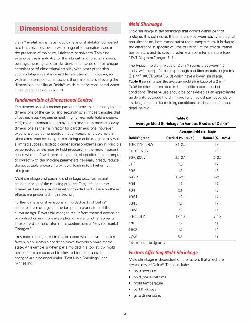
31
Mold ShrinkageMoldshrinkageistheshrinkagethatoccurswithin24hrofmolding .Itisdefinedasthedifferencebetweencavityandactualpartdimension,bothmeasuredatroomtemperature .ItisduetothedifferenceinspecificvolumeofDelrin®atthecrystallizationtemperatureanditsspecificvolumeatroomtemperature(see“PVTDiagrams,”pages5,6) .
ThetypicalmoldshrinkageofDelrin®resinsisbetween1 .7and2 .2%,exceptforthesupertoughandfiber-containinggrades(Delrin®100ST,500AF,570)whichhavealowershrinkage .Table 6summarizestheaveragemoldshrinkageofa2mm(0 .08in)thickpartmoldedinthespecificrecommendedconditions .Thesevaluesshouldbeconsideredasanapproximateguideonly,becausetheshrinkageforanactualpartdependsonitsdesignandonthemoldingconditions,asdescribedinmoredetailbelow .
Table 6 Average Mold Shrinkage for Various Grades of Delrin®
Average mold shrinkage
Delrin® grade Parallel (% ± 0.2%) Normal (% ± 0.2%)
100P, 111P, 127UV 2.1–2.2 1.9
311DP, 327 UV 1.9 1.8
500P, 527UV 2.0–2.1 1.9–2.0
511P 1.8 1.7
900P 1.9 1.9
colors* 1.8–2.1 1.7–2.0
500T 1.7 1.7
100T 2.1 1.9
100ST 1.3 1.4
500TL 1.8 1.7
500AF 2.0 1.4
500CL, 500AL 1.8–1.9 1.7–1.8
570 1.2 2.1
510GR 1.0 1.4
525GR 0.4 1.2
* depends on the pigments
Factors Affecting Mold ShrinkageMoldshrinkageisdependentonthefactorsthataffectthecrystallinityofDelrin® .Theseinclude:
• holdpressure
• hold(pressure)time
• moldtemperature
• partthickness
• gatedimensions
Dimensional Considerations
Delrin®acetalresinshavegooddimensionalstability,comparedtootherpolymers,overawiderangeoftemperaturesandinthepresenceofmoisture,lubricantsorsolvents .Theyfindextensiveuseinindustryforthefabricationofprecisiongears,bearings,housingsandsimilardevices,becauseoftheiruniquecombinationofdimensionalstabilitywithotherproperties,suchasfatigueresistanceandtensilestrength .However,aswithallmaterialsofconstruction,therearefactorsaffectingthedimensionalstabilityofDelrin®whichmustbeconsideredwhenclosetolerancesareessential .
Fundamentals of Dimensional ControlThedimensionsofamoldedpartaredeterminedprimarilybythedimensionsofthecavity,andsecondlybyallthosevariablesthataffectresinpackingandcrystallinity(forexampleholdpressure,HPT,moldtemperature) .Itmayseemobvioustomentioncavitydimensionsasthemainfactorforpartdimensions;howeverexperiencehasdemonstratedthatdimensionalproblemsareoftenaddressedbychangesinmoldingconditions,generallywithalimitedsuccess .Isotropicdimensionalproblemscaninprinciplebecorrectedbychangestoholdpressure .Inthemorefrequentcaseswhereafewdimensionsareoutofspecification,attemptstocorrectwiththemoldingparametersgenerallygreatlyreducetheacceptableprocessingwindow,leadingtoahigherriskofrejects .
Moldshrinkageandpost-moldshrinkageoccurasnaturalconsequencesofthemoldingprocess .Theyinfluencethetolerancesthatcanbeobtainedformoldedparts .Dataontheseeffectsarepresentedinthissection .
FurtherdimensionalvariationsinmoldedpartsofDelrin®canarisefromchangesinthetemperatureornatureofthesurroundings .Reversiblechangesresultfromthermalexpansionorcontractionandfromabsorptionofwaterorothersolvents .Thesearediscussedlaterinthissection,under“EnvironmentalChanges .”
Irreversiblechangesindimensionoccurwhenpolymerchainsfrozeninanunstableconditionmovetowardsamorestablestate .Anexampleiswhenpartsmoldedinatoolatlowmoldtemperatureareexposedtoelevatedtemperatures .Thesechangesarediscussedunder“Post-MoldShrinkage”and“Annealing .”

32
Table 7summarizestheeffectoftheseparametersonmoldshrinkage .Theyarediscussedinmoredetailbelow .
Furthermore,moldshrinkageisalsohighlydependentonthegeometryofthepartandontheflowpatternoftheresin .Experimentshavebeendoneinourlaboratorywith180×27mmplaqueswiththicknessesfrom1 .5to6mm .Fourvaluesofshrinkageweremeasured,closetoandfarfromthegate,parallelandperpendiculartotheflow .FormostDelrin®gradesitisobservedthattheshrinkageishigherfarfromthegatethanclosetothegate(typicallyby0 .1to0 .3%),andthattheshrinkageintheflowdirectionisabout0 .1%higherthantransversetotheflow .
Hold Pressure
Injectionpressurehastwofunctionsinthemoldingprocess:
1 . Transferthemoltenpolymerfromtheinjectionunitintothemold .This“injectionfillpressure”isneededonlytoovercometheresistancetoflowofthepolymerfromtheinjectionunittothecavity .Usuallythisisahighspeedprocess(dynamicphaseofthescrew) .
2 . Controlthepackingandcrystallizationprocess .Theholdpressurepushesmorematerialintothecavitytocompensateforthevolumereductionthatoccursinthepolymerduringcrystallization .Thisisalowspeedprocess(slowmotionofthescrew) .Thisphaseismoreimportantforthedimensionalstabilitysinceithelpsmaintainauniformandgradualcrystallization .Whenalowerholdpressureisused,itwillpacklessmaterialintothecavityandtheshrinkagewillbehigher .ThisisshowninFigure 43forthreemoldtemperatures .
Smallchangesofholdpressuremaybeusedtohelpfinetunethedimensionsofapart,becausethisparameterisessentiallyindependentandhasrelativelysmalladverseeffects .
Notethatholdpressureshouldbeconstantduringthewholepackingtime .
Hold (Pressure) Time (HPT)
Hold(Pressure)Timeisthetimeduringwhichtheholdpressureisapplied .TheHPTisimportantforthevalueofshrinkageanditsuniformityoverthepart .
Figure 44showstheeffectofHPTonmoldshrinkageforDelrin® .
WhentheHPTisbelowtheoptimumvaluerequiredforthespecificpart(seepages27,28),thepackingprocessisinterruptedbeforecompletionandmoldshrinkageishigherthanitsoptimumvalue .Additionalside-effectsofashortHPTareporosity,voids,warpage,sinkmarks,lowermechanicalproperties .
Table 7
Effect on Parameter Shrinkage Remarks
Hold (Pressure) Time ➘ up to optimum HPT, (HPT) then no effect
Hold Pressure ➘
Mold Temperature (cavity) ➚ but post-mold shrinkage ➘
Part Thickness ➙ or ➘ if all settings optimized
Gate Thickness ➘ up to optimum thickness, then no effect
Melt Temperature ➙ if mold temperature is kept constant and HPT is optimized
Key parameters affecting mold shrinkage: Symbol ➚ means that the shrinkage increases when the value of the parameter increases, and the opposite for the symbol ➘. Symbol ➙ means that there is no effect on shrinkage provided that the conditions listed under “Remarks” are met.
Hold pressure, MPa
Mol
d sh
rink
age,
%
140100 12080
1.6
1.7
1.8
1.9
2
2.1
2.2
2.3
1.5
Part thickness 4 mm (0.16 in)Melt temperature 215°C (419°F)
HPT optimized for thickness and mold temperature
Mold temp. = 100°C (212°F)HPT = 43 s
Mold temp. = 90°C (194°F)HPT = 39 s
Mold temp. = 80°C (176°F)HPT = 36 s
Figure 43. Effect of Hold Pressure on Mold Shrinkage at Three Mold Temperatures, for Delrin® 500P. Hold Pressure Can be Used for Small Adjustments of Part Dimensions, as it has Negligible Effect on Post-Molding Shrinkage.
Figure 44. Effect of Hold (Pressure) Time on Mold Shrinkage of Delrin® 500P
Hold (Pressure) Time HPT, s
Mol
d sh
rink
age,
%
10 20 30 40 50 60 70 80 900
2
2.2
2.4
2.6
2.8
3
3.2
3.4
1.8
6 mm
4 mm
1.5 mm
Optimum HPT1.5 mm 10 seconds 4 mm 40 seconds 6 mm 80 seconds
Molding conditions:Hold pressure 90 MPa (13 kpsi)Mold temperature 90°C (194°F)Melt temperature 215°C (419°F)

33
Onthecontrary,anyincreaseofHPTaboveitsoptimumvaluewouldhavenoeffectonmoldshrinkage,becausethepart(andthegate)arealreadysolidified .
Mold Temperature
Moldtemperatureinfluencesmoldshrinkagethroughitseffectoncoolingrateandcrystallizationtemperatureofthemoltenpolymer .TheeffectofmoldtemperatureonshrinkageisalsoshowninFigure 43 .
Athighmoldtemperatures,thepolymercrystallizesslowly .Insuchconditionsthemoldshrinkageishigh,butsincethecrystallizationismorecomplete,abetterlong-termdimensionalstabilityistobeexpectedforthemoldedparts(lesspost-moldshrinkage) .
Lowmoldtemperatures,ontheotherhand,tendtocoolthepolymerataveryhighrate .Thisresultsinalowermoldshrinkageandbettertoughness .However,inthelongterm,higherdimensionalvariationsleadingtobuildupofinternalstresseswilloccur,particularlyifthepartisexposedduringitsend-uselifetotemperaturesexceedingthemoldtemperatureatwhichthepartwasmolded .
Part Thickness
AsshowninFigure 44forDelrin®500P,thethicknesshasaminorinfluenceonmoldshrinkage,providedthatthegatedimensionsandtheHold(Pressure)Timearecorrectforeachthickness .Figure 45showstheshrinkageofvariousDelrin®compositionsvs .partthickness,asmeasuredwithcorrectHPT .Notethat,tooptimizetoughness,themoldtemperatureisreducedfrom90°C(194°F)forthestandardgradesto50°C(122°F)forthetoughenedgrades(withoutleadingtoahighpost-moldingshrinkage) .
Forpartsofuniformwallthickness,themoldshrinkagetendstobeuniform .Inthecaseofvariablethickness,shrinkagewilltendtobenearlyuniformifthepartisgatedintothethickestsection,ifthegateisproperlysizedandiftheHold(Pressure)Timeequalsorexceedsthegatefreezetime .Whenthesecriteriaarenotmet,themoldshrinkagetendstobegreaterforlargersections,withpossibleproblemsofvoids,warpage,sinkmarksandlowermechanicalproperties .
Gate Dimensions
Adequategatedimensionsarerequiredtoensureproperpackingofthepart(see“Gates,”pages14–16) .
Whenthethicknessofthegateissmallerthanitsoptimumvalue,moldshrinkagewillincreaseduetotheprematuresolidificationoftheresinatthegate .ThissituationisthenequivalenttoashorterHold(Pressure)Time,andtheapproximateeffectonshrinkagecanbeobservedinFigure 44 .Inthisrangethemoldshrinkageisnotstable,anditisverydifficulttocontrol .Theresultingwarpagecouldevenmakedifficultthemeasurementofcertaindimensionsofthepart .
Figure 45. Average Mold Shrinkage Versus Thickness, for Various Delrin® Compositions
1.6
Mol
d sr
hink
age,
%
Thickness, mm0
1.2
1
2.2
2
82 4
100P, 500P
500T
100ST
6
1.4
1.8
Melt Temperature
Melttemperaturehasaneffectonmoldshrinkage .Itishoweverlimitedbythenarrowrangeofmelttemperaturesneededtomaintainaconsistentqualityofthemoldedpart .Consequently,themelttemperatureshouldnotbeconsideredasavariabletoadjustmoldshrinkage .
Mold Shrinkage of Filled ResinsThemoldshrinkageofcompositionscontainingfibrousfillers,suchasDelrin®570(glass)andDelrin®500AF(Teflon®),islesspredictable,becauseofthefiberorientationeffects .Theshrinkageinthedirectionofflowtendstobesignificantlydifferentfromthatinthetransversedirection(seeFigure 45) .
Ingeneral,themoldshrinkageofDelrin®500AFintheflowdirectionissimilartothatofDelrin®500P .Themoldshrinkageinthetransversedirection,however,rangesupto50%oftheshrinkageofDelrin®500P .
Incontrast,themoldshrinkageofDelrin®570intheflowdirectionisabouthalfofthatforDelrin®500P .Inthetransversedirection,themoldshrinkageofDelrin®570approachesthatofDelrin®500P .
Effect of PigmentsThepresenceinthemeltofcrystallizationnucleisuchaspigmentsandregrindcanhaveaninfluenceoncrystallizationandconsequentlyonmoldshrinkage .
AnaccuratestudyhasbeencarriedouttoevaluatetheeffectofvarioustypesofpigmentsonthemoldshrinkageofDelrin® .Itappears,asdepictedinFigure 46,thatpigmentsystemsgivingthesameresincolormayhaveadifferenteffectonmoldshrinkageandpartdimensions .

34
Note:Thisstudyhasbeencarriedoutonstandardbarsandintypicalmoldingconditions .Theshrinkagevaluesshownhereshouldnotbeconsideredvalidforallpartsofdifferentgeometryand/ormoldedindifferentmoldingconditions .
Post-Molding ShrinkagePost-moldingshrinkageisdefinedastheshrinkagewhichtakesplacemorethan24hraftermolding .Itisaconsequenceofcontinuedcrystallizationandrelaxationofmolded-instresses,wheretheresinmovestowardsamorestablestate .
Thepost-moldshrinkageofpartsmoldedinDelrin®canbeestimatedfromFigure 47 .
Partsmoldedwiththerecommendedmoldtemperature(90°C[194°F])orhigherwillhavealowpost-moldshrinkage,whichensuresgooddimensionalstabilityoverthelifetimeofthepart .
However,partsmoldedwithacoldmold(<80°C[<176°F])willhaveahigherpost-moldshrinkage,becausefastcoolingleavestheDelrin®inanunstablecrystallinestateandresultsinmoresignificantrecrystallization .IfsuchDelrin®partsarethenexposedtohightemperatures,therecrystallizationcausesahighandrapidpost-moldshrinkage .
Remarks:
1 . Forpartsrequiringtighttolerancesandexposuretoelevatedtemperaturesforprolongedperiodsoftime,itisstronglyrecommendedtousehighmoldtemperatures(upto120°C[248°C]) .Thisprovidesamoreeffectivesolutionthanannealingapartmoldedatlowmoldtemperature .
2 . Forexposureatmoderatetemperatures,gooddimensionalstabilityandpartperformancecanbeachievedusinga90°C(194°C)moldtemperature .
Color
Shri
nkag
e, %
NC-
10
Yello
w
Beig
e
Mau
ve
Whi
te
Red
(1)
Blue
(1)
Blue
(2)
Blac
k
Purp
le
Gree
n (1
)
Gree
n (2
)
Pink
Brow
n
Red
(2)
1.80
1.90
2.00
2.10
2.20
1.70
Figure 47. Post-Molding Shrinkage of Delrin® Acetal ResinsFigure 46. Effect of Selected Pigments on Mold Shrinkage of Delrin® 500P. Part Thickness 2 mm
1.0
Post
-mol
ding
shr
inka
ge, %
Exposure temperature, °C (°F)
50 80 11020
0.2
0
1.2
1.4
1009040 706030
0.4
0.6
0.8
40°C mold
65°C mold
95°C mold
120°C mold
AnnealedAll mold temperatures
0.6
Post
-mol
ding
shr
inka
ge, %
Exposure temperature, °C (°F)
50 80 10020
0.2
0
1.0
11060 70 9030 40
0.4
0.8 40°C
mold
65°C
mold
95°C m
old
120°C mold
AnnealedAll mold temperatures
Thickness – 0.8 mm (0.03 in)
Thickness – 1.6 mm (0.06 in)
0.7
50 80 11020
0.4
01007060 9030 40
0.5
0.6
0.3
0.1
0.2
Thickness – 3.2 mm (0.125 in)
Exposure temperature, °C (°F)Exposure time = 1,000 hr
Post
-mol
ding
shr
inka
ge, %
40°C mold
65°C mold
95°C mold
120°C mold
AnnealedAll mold temperatures
(104) (176)(68) (212)(140)(122) (194)(86) (230)(158)
(104) (176)(68) (212)(140)(122) (194)(86) (230)(158)
(104) (176)(68) (212)(140)(122) (194)(86) (230)(158)
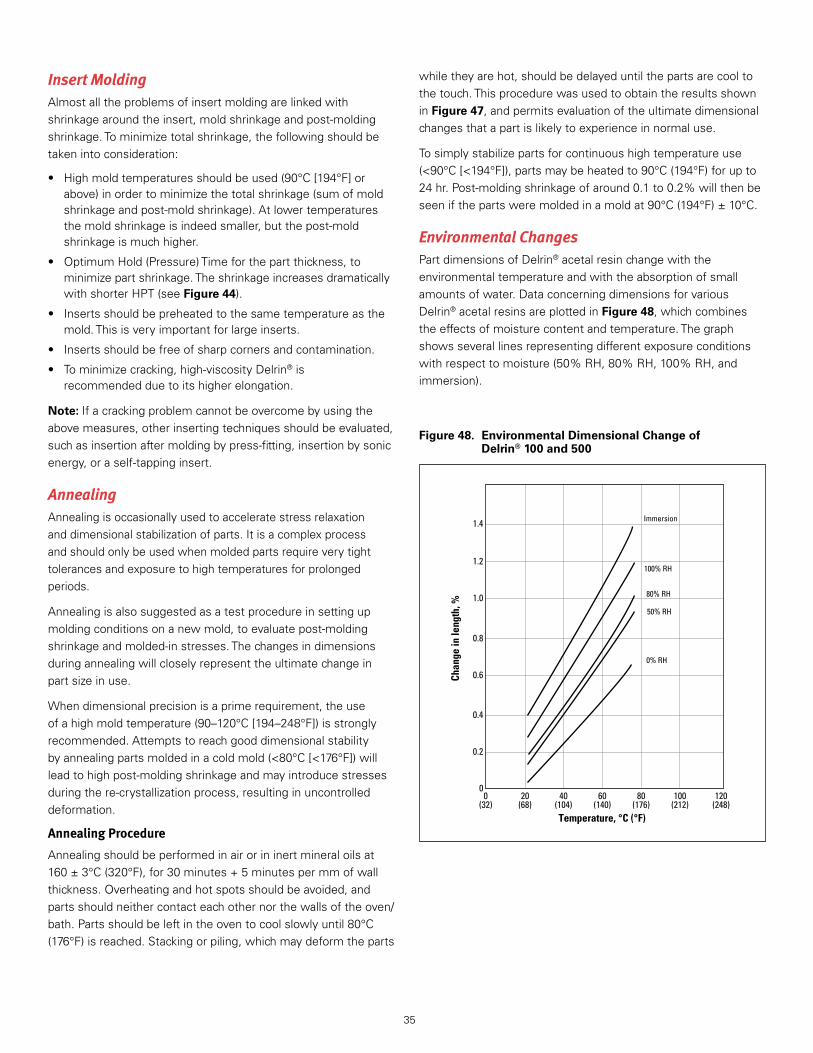
35
Chan
ge in
leng
th, %
12040 8020 100600(248)(104) (176)(68) (212)(140)(32)
0.2
0.4
0.6
0.8
1.0
1.2
1.4
0
Immersion
100% RH
80% RH
50% RH
0% RH
Temperature, °C (°F)
Figure 48. Environmental Dimensional Change of Delrin® 100 and 500
Insert MoldingAlmostalltheproblemsofinsertmoldingarelinkedwithshrinkagearoundtheinsert,moldshrinkageandpost-moldingshrinkage .Tominimizetotalshrinkage,thefollowingshouldbetakenintoconsideration:
• Highmoldtemperaturesshouldbeused(90°C[194°F]orabove)inordertominimizethetotalshrinkage(sumofmoldshrinkageandpost-moldshrinkage) .Atlowertemperaturesthemoldshrinkageisindeedsmaller,butthepost-moldshrinkageismuchhigher .
• OptimumHold(Pressure)Timeforthepartthickness,tominimizepartshrinkage .TheshrinkageincreasesdramaticallywithshorterHPT(seeFigure 44) .
• Insertsshouldbepreheatedtothesametemperatureasthemold .Thisisveryimportantforlargeinserts .
• Insertsshouldbefreeofsharpcornersandcontamination .
• Tominimizecracking,high-viscosityDelrin®isrecommendedduetoitshigherelongation .
Note: Ifacrackingproblemcannotbeovercomebyusingtheabovemeasures,otherinsertingtechniquesshouldbeevaluated,suchasinsertionaftermoldingbypress-fitting,insertionbysonicenergy,oraself-tappinginsert .
AnnealingAnnealingisoccasionallyusedtoacceleratestressrelaxationanddimensionalstabilizationofparts .Itisacomplexprocessandshouldonlybeusedwhenmoldedpartsrequireverytighttolerancesandexposuretohightemperaturesforprolongedperiods .
Annealingisalsosuggestedasatestprocedureinsettingupmoldingconditionsonanewmold,toevaluatepost-moldingshrinkageandmolded-instresses .Thechangesindimensionsduringannealingwillcloselyrepresenttheultimatechangeinpartsizeinuse .
Whendimensionalprecisionisaprimerequirement,theuseofahighmoldtemperature(90–120°C[194–248°F])isstronglyrecommended .Attemptstoreachgooddimensionalstabilitybyannealingpartsmoldedinacoldmold(<80°C[<176°F])willleadtohighpost-moldingshrinkageandmayintroducestressesduringthere-crystallizationprocess,resultinginuncontrolleddeformation .
Annealing Procedure
Annealingshouldbeperformedinairorininertmineraloilsat160±3°C(320°F),for30minutes+5minutespermmofwallthickness .Overheatingandhotspotsshouldbeavoided,andpartsshouldneithercontacteachothernorthewallsoftheoven/bath .Partsshouldbeleftintheoventocoolslowlyuntil80°C(176°F)isreached .Stackingorpiling,whichmaydeformtheparts
whiletheyarehot,shouldbedelayeduntilthepartsarecooltothetouch .ThisprocedurewasusedtoobtaintheresultsshowninFigure 47,andpermitsevaluationoftheultimatedimensionalchangesthatapartislikelytoexperienceinnormaluse .
Tosimplystabilizepartsforcontinuoushightemperatureuse(<90°C[<194°F]),partsmaybeheatedto90°C(194°F)forupto24hr .Post-moldingshrinkageofaround0 .1to0 .2%willthenbeseenifthepartsweremoldedinamoldat90°C(194°F)±10°C .
Environmental ChangesPartdimensionsofDelrin®acetalresinchangewiththeenvironmentaltemperatureandwiththeabsorptionofsmallamountsofwater .DataconcerningdimensionsforvariousDelrin®acetalresinsareplottedinFigure 48,whichcombinestheeffectsofmoisturecontentandtemperature .Thegraphshowsseverallinesrepresentingdifferentexposureconditionswithrespecttomoisture(50%RH,80%RH,100%RH,andimmersion) .

36
Dimensional TolerancesGeneral
Takingintoaccountmolddimensionsandprocessingvariability,experiencesuggeststhatthefollowingdimensionaltolerancesareachievablewithgoodmoldingpractice:
• dimensionsupto150mm(5 .9in): ±0 .15%forprecisionmolding ±0 .3%fortechnicalmolding
• dimensionsabove150mm(5 .9in):±0 .25%forprecisionmolding±0 .4%fortechnicalmolding
Molds
Formulti-cavitymolds,thetoolmakingtolerancesareimportant .Theyhaveadirecteffectonthedimensionaltoleranceofthepart .Asanexample,foramolddimensionof30mm(1 .2in)manufacturedtowithin±0 .01mm,experiencehasshownthatdimensionalconsistencybetterthan±0 .03–0 .04mmcannotbeexpectedforpartsfromdifferentcavitiesinasingleshot .
Molding Conditions
Partsmoldedunderrecommendedconditions(gate,runner,nozzle,screw,machineparameters)asdefinedinthemoldingguidearesubjecttosmallshot-to-shotvariationsindimensions .Anychangeinmachineparametersorconditionswilleffectdimensionaltolerance .Forexample,acoldermoldleadstohigherpost-moldingshrinkage,tooshortHold(Pressure)Timeleadstoinconsistentshrinkage,deformationandlargervariabilityinpartdimensions .

37
Auxiliary OperationsSeveralauxiliaryoperationsassociatedwiththemoldingofDelrin®acetalresinsarediscussedinthissection .Theyincludethefollowingsubjects:
• Materialhandling
• Drying
• Regroundresin
• Coloring
• Disposal
Material HandlingDelrin®acetalresinisshippeddryandneednotbedriedbeforemolding .Resinthathasbeenstoredinacoldwarehouseareashouldbebroughttoroomtemperaturepriortomolding .Thiswillpreventmoisturecondensationandvariationsinheatrequiredtomeltandthusinmelttemperature .
ParticularcareisrequiredforthetoughenedcompositionsofDelrin® .BagsofDelrin®500T,100Tand100STshouldnotbeopeneduntiltheyarereadytobeused .Ifabagisopenedforanysignificantperiodoftimeandtheresinhaspickedupmoisture,thematerialshouldbedriedbeforeitismolded .
PelletsofDelrin®aresurfacelubricatedwithethylenedi-stearamide .Furtherlubricationofthesecompositionsisnotnecessary .
Opencontainerofresinonlyinwell-ventilatedareas .Minimizethegenerationandaccumulationofdust .Additivesinthisproductdonotpresentarespiratoryhazardunlesstheproductisgroundtoapowderofrespirablesizeandthedustisinhaled .Alldustsarepotentiallyinjurioustotherespiratorytractifrespirableproductsaregeneratedandinhaledinsufficientlylargeconcentration .Goodexecutionofhygienepractices,aswithalldusts,shouldincludeprecautiontopreventinhalationofrespirableparticles .
Reground ResinRecommendations to Regrind Delrin®
TheuseofcontaminationfreeanduniformlyregroundDelrin®hasminimalinfluenceonmechanicalpropertiesandmoldingperformanceofstandardgrades(seedetailsbelow) .Toregrindthematerialproperly,thefollowingshouldbeconsidered:
• Donotregrindmoldedparts,spruesorrunnersthatarediscoloredorsplayed—theseconditionsmayindicatethattheresinwasdegradedduringprocessing .
• Avoidaccumulationofregroundresinwheneverpossiblebycontinuousreuseofspruesandrunners .Ideallyregrindatthemoldingmachineandfeedbackimmediatelyusingacloseloopsystemtoavoidanycontamination .Ifgrindingisdone
inabatchprocessawayfromthemoldingmachine,careshouldbetakentoavoidcontaminationofspruesandrunners .Protectregroundresinfromcontaminationanddirtbystoringinclean,dry,clearlylabelled,coveredcontainers .
• Maintainaconstantratioofvirgintoregroundresin,andmixadequatelypriortomolding .Asuitableratiodependsuponthequalityoftheregroundresinandtherequirementsofthepart .A3to1ratioofvirgintoregroundresiniscommon,althoughlargerquantitiesofregroundresincanbeusedsuccessfully .
• Ideallyusealowspeedgrinder,buthigherspeedgrindersareacceptableifknivesarewellsharpenedandifholesinthescreenarelargeenough(4mm)toavoidfines .Thegrindershouldbethoroughlycleanedbeforegrindingadifferentmaterial .
• Excessivefinesshouldberemoved .
• Avoidreprocessedresinfromoutsidesources .
• Foroptimumpropertiesoftoughenedgrades,spruesandrunnersshouldberegroundandusedassoonaspossible,asmoisturepick-upisfastfortheseresins(seepreviousparagraph) .Thefractionofregrindforthesecompositionsshouldnotexceed25%inthefeed,anditshouldbefedimmediatelybackintothehopper .
Effect on Mechanical Properties
Figure 49showstheresultsofa10passregrindstudywhichhasbeenrunusingeither100%or50%regrindwithDelrin®500 .A10pass50%additionregrindstudyisequivalenttoamoldercontinuouslyregrinding50%oftheshotweight .Excellentretentionofmechanicalpropertiesisobservedintheseconditions .
DryingAsageneralrule,Delrin®doesnotrequiredrying .Howeverdryingisrecommendedinsomecases .
Standard Grades
• Whenaresincontainerstaysopenforasignificanttime,dryingat80°C(176°F)fortwohoursmayimprovethemeltquality .ThewaterabsorptionrateofDelrin®acetalresinsatvarioushumiditylevelsisshowninFigure 49 .
• Whenusingmorethan50%ofthecapacityofthemachine,preheatingtheresinat80°C(176°F)fortwohoursmayimprovethehomogeneityofthemeltanddecreasethetorqueonthescrew .
• Whenthermalstabilityisaconcern(e .g .,withsomedifficultcolors),blowingairat80°C(176°F)throughDelrin®mayhelp .Thiswillresultinlessmolddepositandbettersurfacefinish .
Toughened Grades
MoldingoftoughenedDelrin®compositionswithexcessivemoisture(>0 .05%)hasanegativeeffectontoughness .Therefore,itisrecommendedthattheresinisdriedfor4hrat80°C(176°F)inadehumidifieddryer(seethedryingbehaviorofDelrin®100STinFigure 50) .

38
Figure 50. Drying Behavior of Delrin® 100ST
Time, hr
Moi
stur
e, %
53 41 20
0.1
0.2
0.3
0.4
0.5
0.6
0
Hopper dryertemperature : 80°C (176°F)
Dew point : –23°C (–9°F)
Figure 49. Rate of Water Aborption at Various Conditions
Measurements were made on a shallowlayer of Delrin® molding powder.
Note:
Time, days
Wat
er b
y w
eigh
t, %
10 20 30 40 50 600
0.2
0.4
0.6
0.8
0
100% RH, 25°C (77°F)
83% RH, 25°C (77°F)
50% RH, 25°C (77°F)
12% RH, 25°C (77°F)
Delrin® 100, 500, and 900
At23°C(73°F)and50%RH,Delrin®100STpicksup0 .1%moisturein4hr;at30°C(86°F)and85%RHitwillpickup0 .3%moisturein2hr .Forthisreasonrunnersandspruesshouldberegroundandreusedassoonaspossible .
ColoringDelrin®isavailableinarangeofstandardandcustomcolors .
WhenmoldingnaturalDelrin®withacoloringsystemfromamanufacturerotherthanDuPont,thefollowingshouldbenoted:
• Thepigmentormasterbatchmanufacturer’ssafehandlingproceduresmustbeapplied .
• Smallscaletestsshouldberuninitiallytocheckmeltstability(seepage12,foamingtest),assomeacidic,basicormetallicpigmentswilldecomposeDelrin® .
• Differentcoloringsystems(eventhosegivingthesamecolor)couldcausedifferentshrinkages,ascanbeseenfromFigure 46 .Partdimensionsshouldbecheckedinthesmallscaletests .
• Flowalonginjectionunitscrewsislaminarandcolordispersioncouldbeunsatisfactory .Apropermixingheadshouldbeused(seepage9) .
• Totalpigmentloadingshouldbeaslowaspossibletomaintainresinproperties .
DisposalWastedisposalmustbeinaccordancewithallapplicableregulations .Preferredoptionsfordisposalare:
1 . recycling,
2 . incinerationwithenergyrecovery,and
3 . landfill .
Recyclingofsprueandrunnersisbestdonedirectlyatthemoldingmachine(seeRegroundResin,pages34–35) .Mechanicalrecyclingofpost-consumerpartsisrarelyattractive .Sinceresinstabilityandmechanicalpropertiescanbeseverelyaffectedbycontamination,theseparationandcleaninglogisticsbecomecomplicatedandexpensive .Chemicalrecyclingistechnicallypossible,butagainitispresentlylimitedbywastecollectionandseparation .
Thehighfuelvalueofacetalresinsmakesoption(2)verydesirableformaterialthatcannotberecycled .However,partsorregrindofresinscontainingTeflon®(suchasDelrin®500AFand520MP)shouldnotbeincinerated .

39
Troubleshooting GuideProblem Suggested remedies (listed in order of convenience)
Melt quality problemsMold deposit • Decrease injection fill rate • Decrease melt temperature • Avoid resin contamination • Correct hold-up spots in cylinder, screw, nozzle assembly • Increase gate size, flare gate • Enlarge vents • Change vent location • Use hopper drier to improve the resin’s thermal stability in extreme casesOdor • Observe melt appearance (gassing) and measure melt temperature • Reduce cylinder temperatures if melt temperature is high • Avoid resin contamination • Reduce overall cyle to decrease holdup time • Correct holdup spots in cylinder, adaptor, nozzle, screw tip, and check valve assembly • Use smaller injection unitUnmelted particles • Increase cylinder temperatures • Increase back pressure • Reduce screw rpm • Use hopper drier to preheat resin • Increase overall cycle • Use screw designed for Delrin®
• Use larger machine or injection unitScrew deposit • Lessen severity of screw (esp. for Delrin® 100 flow grades)—within recommendations • Avoid overcooling the feed throat • Check % of feed/transition/metering—within recommendationsBlack spots or brown streaks • Decrease residence time in injection unit (smaller screw) • Avoid resin contamination • Correct holdup spots in cylinder, screw, nozzle assembly • Check hopper cooling (80–90°C [176–194°F])Pigment streaks • Increase back pressure to improve dispersion • Use a mixing head screw • Evaluate other coloring systems • Evaluate fully precompounded colorFilling problemsShort shots • Maintain uniform pad • Repair leaking back flow valve if pad cannot be maintained • Increase injection fill pressure • Increase injection fill rate • Increase melt temperature • Increase mold temperature • Enlarge vents • Change vent location • Increase overall cycle • Use screw designed for Delrin®
• Use larger machine or injection unitNote: Minimize nozzle length when molding at or near limit of injection pressure capacity of molding equipment. This will be particularly true for Delrin®100 type resins having high melt viscosity.
Voids in parts • Increase hold pressure • Increase hold (pressure) time • Locate gate in thickest area • Decrease injection fill rate • Decrease melt temperature; improve melt uniformity • Repair leaking back flow valve if pad cannot be maintained • Enlarge vents • Improve gate thickness or location • Eliminate any restrictions in runner or nozzleWeak weld lines • Increase hold pressure • Adjust injection fill rate (around 1 s per mm of part thickness) • Increase melt temperature, but avoid excessive temperature • Enlarge vents • Increase mold temperature • Avoid mold release spray • Change vent or gate location • Use larger machine or injection unit
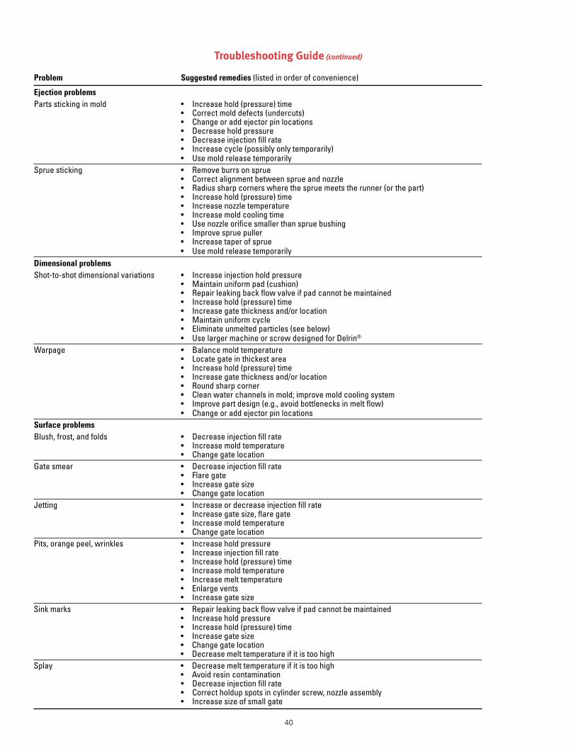
40
Troubleshooting Guide (continued)
Problem Suggested remedies (listed in order of convenience)
Ejection problemsParts sticking in mold • Increase hold (pressure) time • Correct mold defects (undercuts) • Change or add ejector pin locations • Decrease hold pressure • Decrease injection fill rate • Increase cycle (possibly only temporarily) • Use mold release temporarilySprue sticking • Remove burrs on sprue • Correct alignment between sprue and nozzle • Radius sharp corners where the sprue meets the runner (or the part) • Increase hold (pressure) time • Increase nozzle temperature • Increase mold cooling time • Use nozzle orifice smaller than sprue bushing • Improve sprue puller • Increase taper of sprue • Use mold release temporarilyDimensional problemsShot-to-shot dimensional variations • Increase injection hold pressure • Maintain uniform pad (cushion) • Repair leaking back flow valve if pad cannot be maintained • Increase hold (pressure) time • Increase gate thickness and/or location • Maintain uniform cycle • Eliminate unmelted particles (see below) • Use larger machine or screw designed for Delrin®
Warpage • Balance mold temperature • Locate gate in thickest area • Increase hold (pressure) time • Increase gate thickness and/or location • Round sharp corner • Clean water channels in mold; improve mold cooling system • Improve part design (e.g., avoid bottlenecks in melt flow) • Change or add ejector pin locationsSurface problemsBlush, frost, and folds • Decrease injection fill rate • Increase mold temperature • Change gate locationGate smear • Decrease injection fill rate • Flare gate • Increase gate size • Change gate locationJetting • Increase or decrease injection fill rate • Increase gate size, flare gate • Increase mold temperature • Change gate locationPits, orange peel, wrinkles • Increase hold pressure • Increase injection fill rate • Increase hold (pressure) time • Increase mold temperature • Increase melt temperature • Enlarge vents • Increase gate sizeSink marks • Repair leaking back flow valve if pad cannot be maintained • Increase hold pressure • Increase hold (pressure) time • Increase gate size • Change gate location • Decrease melt temperature if it is too highSplay • Decrease melt temperature if it is too high • Avoid resin contamination • Decrease injection fill rate • Correct holdup spots in cylinder screw, nozzle assembly • Increase size of small gate

41
Du
Po
nt
En
gin
eeri
ng
Po
lym
ers
Mo
ldin
g D
ata
Rec
ord
JOB
MO
LD D
ESCR
IPTI
ON
M
ACH
INE
SETU
P IN
STRU
CTIO
NS
SPEC
IAL
INST
RUCT
ION
S
OPE
RATO
RS
SCRE
W U
SED
SA
FETY
CH
ECK
ENG
INEE
RSPR
ESS
NO
. N
OZZ
LE #
COM
MEN
TS O
N M
OLD
ING
OPE
RATI
ON
, STA
RT-U
P, E
TC.
PAG
E N
O.
DAT
E
TIM
E
Run Number
Resin
Lot Number
Rear
Center
Front
Nozzle
Fixed
Movable
Melt
Clamp (Tons)
Back
Injection
Hold
Open
Overall
Booster
Ram in Motion
ScrewRetraction
Pad (Inches)
RPM
Full Shot
Part Only
Injection1st Stage
Injection2nd Stage
TEM
PERA
TURE
S,
C (
F)PR
ESSU
RES,
MPa
(PSI
)CY
CLE
TIM
ES, s
ecW
EIG
HTS
, gRE
MA
RKS

42
E
Ejection . . . . . . . . . . . . . . . . . . . . . . . . . . . . . . . . . . . . . . . . . . . . . 3,20,26,29,39,40Elongation . . . . . . . . . . . . . . . . . . . . . . . . . . . . . . . . . . . . . . . . . . . . . . . . . . . . . . . . 2,7,30,35EmergencyShutdown . . . . . . . . . . . . . . . . . . . . . . . . . . . . . . . . . . . . . . . . . . . . . . . . . . . 23EnvironmentalDimensionalChange . . . . . . . . . . . . . . . . . . . . . . . . . . . . . . 35
F
FillRate . . . . . . . . . . . . . . . . . . . . . . . . . . . . . . . . . . . . . . . . . . . . . . . . . . . . . . . . . . . . . . 27,39,40Flash . . . . . . . . . . . . . . . . . . . . . . . . . . . . . . . . . . . . . . . . . . . . . . . . . . . . . . . . . . . . . . . . . . . . . . . 20,27Flow . . . . . . . . . . . . . . . . . . . . . . . . . . . .4–11,13,14–21,23–28,29,32,33FoamingTest . . . . . . . . . . . . . . . . . . . . . . . . . . . . . . . . . . . . . . . . . . . . . . . . . . . . . . .11,12,38Formaldehyde . . . . . . . . . . . . . . . . . . . . . . . . . . . . . . . . . . . . . . . . . . . . . . . . . . . . . . . 1,3,22
G
Gassing . . . . . . . . . . . . . . . . . . . . . . . . . . . . . . . . . . . . . . . . . . . . . . . . . . . . . . . . . . . . . . . . . . . .11,39GateDesign . . . . . . . . . . . . . . . . . . . . . . . . . . . . . . . . . . . . . . . . . . .14,15,16,22,27GateFreezeTime . . . . . . . . . . . . . . . . . . . . . . . . . . . . . . . . . . . . . . . . . . . . . . . . . . . . . . . . . . . 33GateLocation . . . . . . . . . . . . . . . . . . . . . . . . . . . . . . . . . . . . . . . . . . . . . . . . . . . .14,39,40GateSize . . . . . . . . . . . . . . . . . . . . . . . . . . . . . . . . . . . . . . . . . . . . . . . . . . . . . . . . . . . . . . . . . 39,40GateSmear . . . . . . . . . . . . . . . . . . . . . . . . . . . . . . . . . . . . . . . . . . . . . . . . . 26,34,39,40Gates . . . . . . . . . . . . . . . . . . . . . . . . . . . . . . . . . . . . . . . . . . . . . . . . .6,9,13,14,17,19,32GlassTransitionTemperature . . . . . . . . . . . . . . . . . . . . . . . . . . . . . . . . . . . . . . . 4,5Gloss . . . . . . . . . . . . . . . . . . . . . . . . . . . . . . . . . . . . . . . . . . . . . . . . . . . . . . . . . . . . . . . . . . . . . . . . . . . . . 27
H
HandlingPrecautions . . . . . . . . . . . . . . . . . . . . . . . . . . . . . . . . . . . . . . . . . . . . . . . . . . . . . . 23HeatofFusion . . . . . . . . . . . . . . . . . . . . . . . . . . . . . . . . . . . . . . . . . . . . . . . . . . . . . . . . . . . . . . . . . . 6Hold-upareas . . . . . . . . . . . . . . . . . . . . . . . . . . . . . . . . . . . . . . . . . . . . . . . . . . . . . . . . . . . . . . . . . . . . 3Hold-UpTime . . . . . . . . . . . . . . . . . . . . . . . . . . . . . . . . . . . . . . . . . . . . . . . . . . . . . . . . . . . . . . 8,24
I
InjectionPressure . . . . . . . . . . . . . . . . . . . . . . . . . . . . . . . . . . . . . . . . . . . . . . . . 27,32,39InjectionRate . . . . . . . . . . . . . . . . . . . . . . . . . . . . . . . . . . . . . . . . . . . . . . . . . . . . . . . . . . . . . . . . . . 27InsertMolding . . . . . . . . . . . . . . . . . . . . . . . . . . . . . . . . . . . . . . . . . . . . . . . . . . . . . . . . . . . . . . . . 35ISO . . . . . . . . . . . . . . . . . . . . . . . . . . . . . . . . . . . . . . . . . . . . . . . . . . . . . . . . . . . . . . . . . . . . . . . . . . . . 29,30
J
Jetting . . . . . . . . . . . . . . . . . . . . . . . . . . . . . . . . . . . . . . . . . . . . . . . . . . . . . . . . . . . . 14,27,39,40
L
Lubricants . . . . . . . . . . . . . . . . . . . . . . . . . . . . . . . . . . . . . . . . . . . . . . . . . . . . . . . . . . . . . . . . . . . 3,31
Index
A
Adaptor . . . . . . . . . . . . . . . . . . . . . . . . . . . . . . . . . . . . . . . . . . . . . . . . . . . . . . . . . . . .8,9,10,39AirShots . . . . . . . . . . . . . . . . . . . . . . . . . . . . . . . . . . . . . . . . . . . . . . . . . . . . . . . . . . . . . . . . . . . . . 1,3AirTrapping . . . . . . . . . . . . . . . . . . . . . . . . . . . . . . . . . . . . . . . . . . . . . . . . . . . . . . . . . . . . . . . . . . . . .14Annealing . . . . . . . . . . . . . . . . . . . . . . . . . . . . . . . . . . . . . . . . . . . . . . . . . . . . . . . . . . 31,34,35
B
BackFlowValve . . . . . . . . . . . . . . . . . . . . . . . . . . . . . . . . . . . . . . . . .8,9,10,39,40BackPressure . . . . . . . . . . . . . . . . . . . . . . . . . . . . . . . . . . . . . . . . . . . . . .12,25,30,39Blowback . . . . . . . . . . . . . . . . . . . . . . . . . . . . . . . . . . . . . . . . . . . . . . . . . . . . . . . . . . . . . . . . . . 3,23BrownStreaks . . . . . . . . . . . . . . . . . . . . . . . . . . . . . . . . . . . . . . . . . . . . . . . . . . . . . . . . .11,38Burning . . . . . . . . . . . . . . . . . . . . . . . . . . . . . . . . . . . . . . . . . . . . . . . . . . . . . . . . . . . . . . . . . . . . . . . . . .19
C
CAVANCavityAnalysis . . . . . . . . . . . . . . . . . . . . . . . . . . . . . . . . . . . . . . . . . . . . . . . . . . 30CavityPressure . . . . . . . . . . . . . . . . . . . . . . . . . . . . . . . . . . . . . . . . . . . . . . . . . . . . . . . . . . . . . 30CheckRing . . . . . . . . . . . . . . . . . . . . . . . . . . . . . . . . . . . . . . . . . . . . . . . . . . . . . . . . . . . . . . . 10,11ClampingForce . . . . . . . . . . . . . . . . . . . . . . . . . . . . . . . . . . . . . . . . . . . . . . . . . . . . . . . 28,29Coloring . . . . . . . . . . . . . . . . . . . . . . . . . . . . . . . . . . . . . . . . . . . . . . . . . . .8,12,36,38,39Compositions . . . . . . . . . . . . . . . . . . . . . . . . . . . . . . . . . . . . . . . . . . . . . . . . . . . . . . 1,33,37Compressionratio . . . . . . . . . . . . . . . . . . . . . . . . . . . . . . . . . . . . . . . . . . . . . . . . . . . . . . . . . . 9Contamination . . . . . .8,10,11,12,23,25,29,35,36,37,38Corrosion . . . . . . . . . . . . . . . . . . . . . . . . . . . . . . . . . . . . . . . . . . . . . . . . . . . . . . . . . . .10,20,26Crystallinity . . . . . . . . . . . . . . . . . . . . . . . . . . . . . . . . . . . . . . . . . . . . . . . . . . . . . . . . . . . . . . . . . . . 31Cushion . . . . . . . . . . . . . . . . . . . . . . . . . . . . . . . . . . . . . . . . . . . . . . . . . . . . . . . . . . . . . 28,38,40Cycle . . . . . . . . . . . . . . . . . . . . . . . . .1,3,5,8,9,10,11,12,13,18,20,21, . . . . . . . . . . . . . . . . . . . . . . . . . . . . . . . . . . . . . . . . . . . . . . 24,25,26,28,29,30,39,40CycleEstimation . . . . . . . . . . . . . . . . . . . . . . . . . . . . . . . . . . . . . . . . . . . . . . . . . . . . . . . . . . . 26CylinderTemperatureControl . . . . . . . . . . . . . . . . . . . . . . . . . . . . . . . . . . . . . . . .10
D
Decomposition . . . . . . . . . . . . . . . . . . . . . . . . . . . . . . . . . . . . . . . . . . . . . . . . . . . . . 1,3,23Degradation . . . . . . . . . . . . . . . . . . . . . . . . . . . . . . . . . . . . . . 8–11,19,22,25,29Delrin®100P . . . . . . . . . . . . . . . . . . .1,2,9,13,21,25,28,30,3539Delrin®100ST . . . . . . . . . . . . . . . . . . . . . . . . . . . . . . . 2,24,25,30,31,37,38Delrin®111P . . . . . . . . . . . . . . . . . . . . . . . . . . . . . . . . . . . . . . . . . . . . . . . . . . . . . . . . . . . . . . . . . . . . 2Delrin®500AF . . . . . . . . . . . . . . . . . . . . . . . . . . . . . . . . . . . . . . . . . . . . . . . . . . . . . 2,33,38Delrin®500CL . . . . . . . . . . . . . . . . . . . . . . . . . . . . . . . . . . . . . . . . . . . . . . . . . . . . . . . . . . . . . . . . . 2Delrin®500P . . . . . . . . . . . . . . . . . . . . .1,2,7,9,25,27,28,30,33,34Delrin®500T . . . . . . . . . . . . . . . . . . . . . . . . . . . . . . . . . . . . . . . . . . . . . . . . . 2,24,30,36Delrin®511P . . . . . . . . . . . . . . . . . . . . . . . . . . . . . . . . . . . . . . . . . . . . . . . . . . . . . . . . . . . . . . . . . . . . 2Delrin®570 . . . . . . . . . . . . . . . . . . . . . . . . . . . . . . . . . . . . . . . . . . . . . . . . . . . . . . . . . 2,25,33Delrin®900P . . . . . . . . . . . . . . . . . . . . . . . . . . . . . . . . . . . . . . . . . . . . . . . . . . . . . . . . . . . . . . . . . . . 2DimensionalStability . . . . . . . . . . . . . . . . . . . . . . . . . . 1,4,33,34,34,35Disposal . . . . . . . . . . . . . . . . . . . . . . . . . . . . . . . . . . . . . . . . . . . . . . . . . . . . . . . . . . . . . . . . . . . 36,38Drool . . . . . . . . . . . . . . . . . . . . . . . . . . . . . . . . . . . . . . . . . . . . . . . . . . . . . . . .3,11,19,24,25Drying . . . . . . . . . . . . . . . . . . . . . . . . . . . . . . . . . . . . . . . . . . . . . . . . . . . . . . . . . . 30,36,37,38

43
M
MaterialHandling . . . . . . . . . . . . . . . . . . . . . . . . . . . . . . . . . . . . . . . . . . . . . . . . . . . . . . . . . . . . 36MeltOutput . . . . . . . . . . . . . . . . . . . . . . . . . . . . . . . . . . . . . . . . . . . . . . . . . . . . . . . . . . . . . . . . . . . . 24MeltTemperature . . . . . . . . . . . . . . . . . . 1,6–9,12,13,23–25,33,36MeltViscosity . . . . . . . . . . . . . . . . . . . . . . . . . . . . . . . . . . . . . . . . . . . 1,4,6,7,13,39MoldDeposit . . . . . . . . . . . . . . . . . . . . . . . . . . . . . . . . . . 8,12,17,19,20,37,39MoldDesign . . . . . . . . . . . . . . . . . . . . . . . . . . . . . . . . . . . . . . . . . . . . . . . . . . . . . . . .11,12,25Molded-inStresses . . . . . . . . . . . . . . . . . . . . . . . . . . . . . . . . . . . . . . . . . . . . . . 27,34,35MoldMaintenance . . . . . . . . . . . . . . . . . . . . . . . . . . . . . . . . . . .13,19,20,22,28MoldOpenTime . . . . . . . . . . . . . . . . . . . . . . . . . . . . . . . . . . . . . . . . . . . . . . . . . . . . . . . 26,29MoldShrinkage . . . . . . . . . . . . . . . . . . . . . . . . . . . . . . . . . .13,20,25,28,30–35MoldTemperature . . . . . . . . . . . . . . . . . . . . . . . . . . . . . . .20,22,25–27,30–35
N
Non-ReturnValve . . . . . . . . . . . . . . . . . . . . . . . . . . . . . . . . . . . . . . . . . . . . . . . . . . . . . . . 10,11Nozzle . . . . . . . . . . . . . . . . . . . . . .1,3,–12,14,17,22,23,24,27,29,36
O
Odor . . . . . . . . . . . . . . . . . . . . . . . . . . . . . . . . . . . . . . . . . . . . . . . . . . . . . . . . . . .3,19,22,24,39OpenNozzle . . . . . . . . . . . . . . . . . . . . . . . . . . . . . . . . . . . . . . . . . . . . . . . . . . . . . . . . . . . . . . . . . . . .11OptimumProductivity . . . . . . . . . . . . . . . . . . . . . . . . . . . . . . . . . . . . . .9,10,22,29
P
Packaging . . . . . . . . . . . . . . . . . . . . . . . . . . . . . . . . . . . . . . . . . . . . . . . . . . . . . . . . . . . . . . . . . . . . . . . . . . 3PartWeight . . . . . . . . . . . . . . . . . . . . . . . . . . . . . . . . . . . . . . . . . . . . . . . . . . . . . . . . . . . . . . . . . . . . . 28Pigments . . . . . . . . . . . . . . . . . . . . . . . . . . . . . . . . . . . . . . . . . . . . . . 8,9,30,31,34,38Post-moldingshrinkage . . . . . . . . . . . . . . . . . . . . . . . . . . . . . . . . . . . . . . . . . . . . .32–36ProjectedArea . . . . . . . . . . . . . . . . . . . . . . . . . . . . . . . . . . . . . . . . . . . . . . . . . . . . . . . . . . 28,29Purging . . . . . . . . . . . . . . . . . . . . . . . . . . . . . . . . . . . . . . . . . . . . . . . . . . . . . . . . . . . . . . . . . . . . . . . . . . . 22
R
Recycling . . . . . . . . . . . . . . . . . . . . . . . . . . . . . . . . . . . . . . . . . . . . . . . . . . . . . . . . . . . . . . . . . . . . . . . . 38RegroundResin . . . . . . . . . . . . . . . . . . . . . . . . . . . . . . . . . . . . . . . . . . . . . . . . . . . . . . . . . 37,38Runner . . . . . . . . . . . . . . . . . . . . . . . . . . . . . . . . . . .3,9,13,15–20,24,27,29,36RunnerlessMolds . . . . . . . . . . . . . . . . . . . . . . . . . . . . . . . . . . . . . . . . . . . . . . . . . . . . . .13,18Runners . . . . . . . . . . . . . . 6,8,13,14,16–19,23,25,27,29,36–39
S
ScrewDesign . . . . . . . . . . . . . . . . . . . . . . . . . . . .8,9,10,12,25,29,39,40ScrewForwardTime . . . . . . . . . . . . . . . . . . . . . . . . . . . . . . . . . . . . . . . . . . . . . . . . . . . . . . . 26ScrewRetractionTime . . . . . . . . . . . . . . . . . . . . . . . . . . . . . . . . . . . . . . . . .10,26,29ScrewRotation . . . . . . . . . . . . . . . . . . . . . . . . . . . . . . . . . . . . . . . . . . . . . . . 9,24,25,29ScrewRotationSpeed . . . . . . . . . . . . . . . . . . . . . . . . . . . . . . . . . . . . . . . . . . 9,25,29Shutdown . . . . . . . . . . . . . . . . . . . . . . . . . . . . . . . . . . . . . . . . . . . . . . . . . . . . . . . . . . . . . . . . . . . . . . . 23Sinkmarks . . . . . . . . . . . . . . . . . . . . . . . . . . . . . . .4,14,21,28,32,33,39,40SnakeFlowMold . . . . . . . . . . . . . . . . . . . . . . . . . . . . . . . . . . . . . . . . . . . . . . . . . . . . . . . . . . . . .13Splay . . . . . . . . . . . . . . . . . . . . . . . . . . . . . . . . . . . . . . . . . . . . . . . . .3,8,17,19,36,39,40Start-Up . . . . . . . . . . . . . . . . . . . . . . . . . . . . . . . . . . . . . . . . . . . . . . . . . . . . . . . . . . . . . . . . 1,22,23
T
ThermalStability . . . . . . . . . . . . . . . . . . . . . . . . . . . . . . . . . . . . . . . . . . . . . . . . . . . . 8,37,39Tolerances . . . . . . . . . . . . . . . . . . . . . . . . . . . . . . . . . . . . . . . . . . . . . . . .10,31,34,35,36Toughness . . . . . . . . . . . . . . . . . . . . . . . . . . . . . . . . . . . . . . . . . .1,7,9,21,27,33,37Troubleshooting . . . . . . . . . . . . . . . . . . . . . . . . . . . . . . . . . . . . . . . . . . . . . . . . . . 20,39,40
U
Undercuts . . . . . . . . . . . . . . . . . . . . . . . . . . . . . . . . . . . . . . . . . . . . . . . . . . . . . .12,20,39,40UnmeltedParticles . . . . . . . . . . . . . . . . . . . . . . . . . . . . . . . . . . . 9,25,29,39,40
V
Venting . . . . . . . . . . . . . . . . . . . . . . . . . . . . . . . . . . . . . . . . . . .2,14,19,20,21,22,29Voids . . . . . . . . . . . . . . . . . . . . . . . . . . . . . . . . . . . . . . . . . . . . . . . 4,5,28,30,32,33,39
W
Warping . . . . . . . . . . . . . . . . . . . . . . . . . . . . . . . . . . . . . . . . . . . . . . . . . . . . . . . . . . . . . . . . . . . . . . . . . . . . 9WaterAbsorption . . . . . . . . . . . . . . . . . . . . . . . . . . . . . . . . . . . . . . . . . . . . . . . . . . . . . . . . . . . . 37WeldLine . . . . . . . . . . . . . . . . . . . . . . . . . . . . . . . . . . . . . . . . . . . . . . . . . . . . . .14,20,21,29
Index (continued)
Copyright © 2006 DuPont. The DuPont Oval Logo, DuPont™, The miracles of science™, Delrin® , Kevlar®, Teflon®, and ELCee™ Screw are registered trademarks or trademarks of E. I. du Pont de Nemours and Company or its affiliates. All rights reserved.
H-78783-1 (11/06) Printed in the U.S.A.
The data listed here fall within the normal range of properties, but they should not be used to establish specification limits nor used alone as the basis of design. The DuPont Company assumes no obligations or liability for any advice furnished or for any results obtained with respect to this information. All such advice is given and accepted at the buyer’s risk. The disclosure of information herein is not a license to operate under, or a recommendation to infringe, any patent of DuPont or others. Since DuPont cannot anticipate all variations in actual end-use conditions, DuPont makes no warranties and assumes no liability in connection with any use of this information.
CAUTION: This product is not permitted to be sold for use in medical applications involving any implantation in the human body or where contact with internal body fluids or tissues will equal or exceed 24 hours. For applications involving contact of less than 24 hours, see “DuPont Medical Caution Statement”, H-50102 or contact your DuPont sales representative.
plastics.dupont.com
ForfurtherinformationpleasecontactDialDuPontFirstat1-800-441-0575orviae-mail:web-inquires .ddf@usa .dupont .com
AmericasDuPontBMP26-2363LancasterPike&Route141Wilmington,DE19805U .S .A .Telephone+13027741161Toll-Free(USA)8006286208Fax+13029994399
DuPontDoBrasil,S .A .AlamedaItapecuru,50606454-080Barueri,SPBrasilTelephone+551141668542Fax+551141668720
Asia PacificDuPontChinaHoldingCo,Ltd .15thFloor,ShuiOnPlaza333HuaiHaiRoad(Central)Shanghai200021,ChinaTelephone+862163866366Fax+862163866333
DuPontK .K ./DuPontAsiaPacificSannoParkTower11-1Nagatacho2-chomeChiyoda-ku,Tokyo,100-6111Telephone+81355212771Fax+81355212775
Europe/Middle East/AfricaDuPontdeNemoursInt’l .S .A .2,CheminDuPavillonPOBox50CH-1218LeGrandSaconnexGeneva,SwitzerlandTelephone+41227175111Fax+41227175500