duogen-3 water / wind battery...
TRANSCRIPT
DuoGen-3 Water / WindBattery Charger
USER’S MANUAL
Eclectic Energy LimitedUnit 22Sherwood NetworkcentreSherwood Energy VillageOllerton, NottinghamshireNG22 9FDUnited KingdomTelephone: +44 (0)1623 835400 Facsimile: +44 (0)1623 860617Web: www.eclectic-energy.co.uk Email: [email protected]
1
Welcome to DuoGenCongratulations on your purchase of the DuoGen water/wind battery charging system for yachts.
DuoGen is designed and precision manufactured in the UK to provide the most practical and user-friendly systemcurrently available for renewable energy electricity generation on cruising yachts.
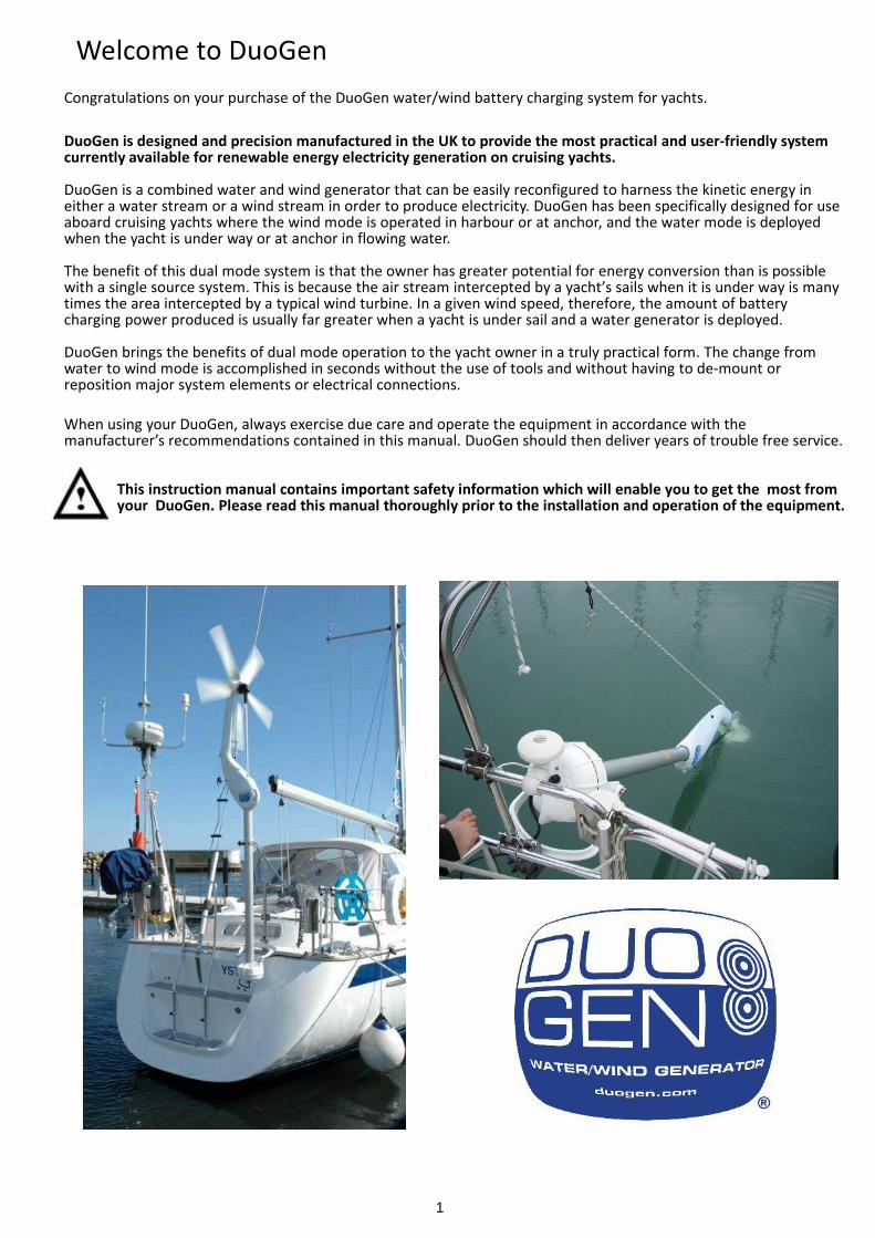
DuoGen is a combined water and wind generator that can be easily reconfigured to harness the kinetic energy ineither a water stream or a wind stream in order to produce electricity. DuoGen has been specifically designed for useaboard cruising yachts where the wind mode is operated in harbour or at anchor, and the water mode is deployedwhen the yacht is under way or at anchor in flowing water.
The benefit of this dual mode system is that the owner has greater potential for energy conversion than is possiblewith a single source system. This is because the air stream intercepted by a yacht’s sails when it is under way is manytimes the area intercepted by a typical wind turbine. In a given wind speed, therefore, the amount of batterycharging power produced is usually far greater when a yacht is under sail and a water generator is deployed.
DuoGen brings the benefits of dual mode operation to the yacht owner in a truly practical form. The change fromwater to wind mode is accomplished in seconds without the use of tools and without having to de-mount orreposition major system elements or electrical connections.
When using your DuoGen, always exercise due care and operate the equipment in accordance with themanufacturer’s recommendations contained in this manual. DuoGen should then deliver years of trouble free service.
This instruction manual contains important safety information which will enable you to get the most from your DuoGen. Please read this manual thoroughly prior to the installation and operation of the equipment.
2
Contents
Renewables on board Page 3 Dual Mode Capability Page 3 Physics of wind energy & Advantages of water generation Page 4 DuoGen features
Safety Page 5 General Safety Page 5 Safe Handling Page 5 Electrical hazard Page 5 Man over board
DuoGen options and installation Page 6 DuoGen variants - tower lengths, standard and high speed impeller Page 7-9 DuoGen mount schematics Page 10 Assembling your DuoGen Page 11 Positioning DuoGen on the transom Page 12-15 DuoGen Universal Mount Bracket Installation Page 16-17 DuoGen component indentification wind and water modes
Electrical installation Page 18 -20 DuoGen electrical installation - Wire sizing and circuit diagrams
Charge Regulation Page 21 Charge Regulation
Operating DuoGen Page 22 -25 Deploying and Operating DuoGen in Wind mode Page 26- 27 Configuring DuoGen for Water mode Page 27 Deploying DuoGen in Water mode Page 27 Operating in Water mode Page 28 -29 Recovering DuoGen from Water mode Page 29 The diving plane
Maintenance Page 30 -31 Routine maintenance, repairs and spares Page 31 Commissioning your DuoGen
System monitoring
Page 31 Log calibration battery monitoring Page 32 Performance & Expectations Page 33 Performace Data Page 34 DuoGen Specifications Page 35-36 Trouble Shooting Diagnosing Problems Page 37 Warranty
3
Renewables Onboard
DuoGen’s Dual mode CapabilityYour DuoGen can generate electricity directly from the wind, or from the yacht’s movement through the water.Wind generation can make a significant contribution to your power needs when anchored off, particularly whencombined with some photovoltaic panels.However on passage no wind generator is at its best. By contrast water generation works superbly once under wayand DuoGen easily re-configures to take advantage of this.
The Advantages of Water GenerationWhen configured as a water powered generator, DuoGen is specifically designed to maximise electricityproduction whilst on passage.At typical passage speeds of 5-6 knots the DuoGen’s output is usually sufficient to balance the power consumed,i.e. 140-200 amp hours per day. Larger yachts which achieve higher average passage speeds in the 7-8 knot rangecan expect yields from the DuoGen of 250-380 amp hours per day.
The DuoGen water generator converts a proportion of the wind energy captured by the yacht’s whole sail planinto electricity. It does this by extracting energy from the boat’s motion through the water.
Water is 800 times denser than air, so a small impeller is all that is required to extract a lot of energy from thewater
The inertia provided by the yacht’s hull evens out the fluctuations in power output typically seen in windgenerators. The result is steady continuous, consistent power production as long as the yacht is underway. Watergeneration is also quiet and vibration-free.
Water generators for yachts are of three main types: tow rope machines where a heavy impeller is pulled on a100 foot line, submersible ‘outboard leg’ type generators, and finally the Eclectic concept characterised by ahydro- dynamic foil or ‘dive plane’ used to control impeller running depth.
The dive plane enables the water impeller unit to ‘fly’ through the water largely unaffected by sea state or themovement of the boat. This optimises the water flow in which the impeller operates, maximising efficency.
The DuoGen can be installed satisfactorily alongside self-steering systems. Allowing 400 –500mm of lateralspacing between the equipment usually ensures there is no chance of contact between the steering’s servo armand the DuoGen.
The Physics of Wind GenerationThe power output from any wind turbine is largely dependent on two factors, the prevailing wind speed and theswept area of the rotor. This swept area is governed by the length of the air blades - the longer they are, thegreater the potential power of the wind generator.Unfortunately, it is not practical to fit very large wind turbines on yachts, and machines with rotor diameters ofaround 1 metre are the norm. The amount of energy available in a wind stream varies as the cube of its velocity -for example, there is over 70% more energy available at 12 mph than at 10 mph. Very low wind speeds containvery little energy, so although a wind turbine may spin, it will produce little or no power. With increasing windspeed, output from the turbine rises exponentially. Wind is a variable but occasionally very powerful resource,and sensible sailors tend to avoid its worst excesses. Where possible, sailors will sail downwind and anchor insheltered spots, all of which reduces the energy available to a yacht-mounted wind generator.
Given these constraints, a dedicated wind generator is unlikely to keep pace with all electricity usage on a dailybasis. It can, however, make a very useful contribution to the energy budget.
The DuoGen is different.
By deploying the water mode when you go cruising:
● The DuoGen taps into the wind power that the yacht’s whole sail area intercepts.● This is many times greater than that of a yacht-sized turbine.● At typical cruising speeds, the DuoGen in water mode produces enough power to run most if not all of the
yacht’s electrics.● The DuoGen’s water mode is much more efficient than a wind generator at sea and much easier to live with.
4
DuoGen Features
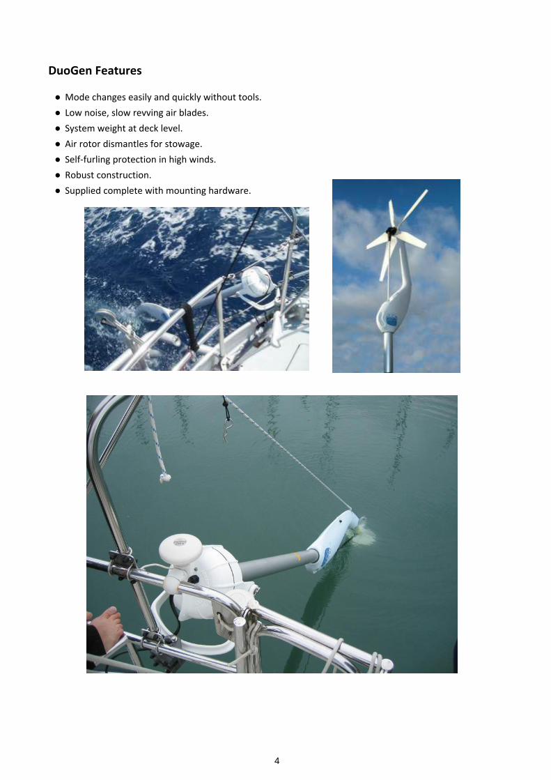
● Mode changes easily and quickly without tools.● Low noise, slow revving air blades.● System weight at deck level.● Air rotor dismantles for stowage.● Self-furling protection in high winds.● Robust construction.● Supplied complete with mounting hardware.
5
Safety
WARNING: the DuoGen should never be allowed to operate if it is not connected to a battery. This conditionallows the machine to over-speed and very high voltages can be produced.
General Safety
As with all electrical and mechanical equipment, precautions should be taken when handling, installing andoperating the DuoGen water generator. We advise that you familiarise yourself with the product manual and thesafety information it contains. In particular do not underestimate the weight and size of the unit when installing orremoving the DuoGen from the yacht. Never try to slow or stop the water impeller or drive shaft with your hands.
Installation
When installing the DuoGen due care should be exercised at all times. The DuoGen weighs 17.6kg and is awkwardin shape with the weight concentrated at one end. It is sensible to approach installation in a methodical mannerand to enlist some help when attaching or removing the machine from the transom.
If possible, install the Duogen when the yacht is ashore. If this not practicable, installing in a marina with the yachtsecured stern to a pontoon is a good alternative. The pontoon provides a safe and convenient working platform.A dinghy can be lashed across the transom in order to provide additional security, if work has to be done at anchor.
Safe Handling
The DuoGen alternator, yoke and ‘c‘ bracket mountings incorporate pivots to allow freedom of movement bothvertically and horizontally. Although designed with generous clearances, care should be taken to avoid trappinghands and fingers when handling the DuoGen.
Care should be taken when dismantling and re-assembling the air turbine rotor as, for maximumaerodynamic efficiency, the blades feature fine trailing edges which can cause injury if not handled with cautionIn wind mode, as with all wind turbines, the major hazard lies in accidental contact with the turbine blades.Although the DuoGen's blades run more slowly than many competitor machines, they are still capable of inflictinginjury. When correctly installed and operating, the DuoGen's air blades are safely above head height. By using thehandle on the machine's yaw arm, DuoGen can quickly be stopped even in severe conditions,without any risk ofinjury from the blades.
NOTE: DuoGen should always be stopped using the moulded yaw arm handle, even where an electrical brake switch is fitted..
The DuoGen is a very robustly engineered product. However the alternator contains high energy ferrite magneticrotors. Ferrite is a brittle material that can suffer damage if the alternator is dropped or handled heavily.
Electrical Hazards
When operating, the DuoGen is capable of producing high voltages, particularly if disconnected from the batteries.Caution should be exercised at all times to avoid electric shock.
Always observe correct polarity when connecting the DuoGen to the regulator and the batteries. Reverse polarityconnection will result in damage to the alternator.
The DuoGen must be appropriately fused at all times.
Connecting cables must be of a suitable gauge and rating. Disconnect at the batteries before attemptingmaintenance.
The use of deck plugs and sockets is not recommended. These can become accidentally unplugged, and the plugpins then constitute a shock hazard.
Dump resistors associated with charge regulators can become very hot once the batteries are full. Avoid touchingthese resistors and do not restrict the airflow around them with clothing, sail bags or similar.
Man OverboardThe DuoGen should be recovered immediately if people are in the water. The spinning water impeller can causeserious injury.
6
DuoGen Options and Installation
DuoGen Variants and Tower length selection
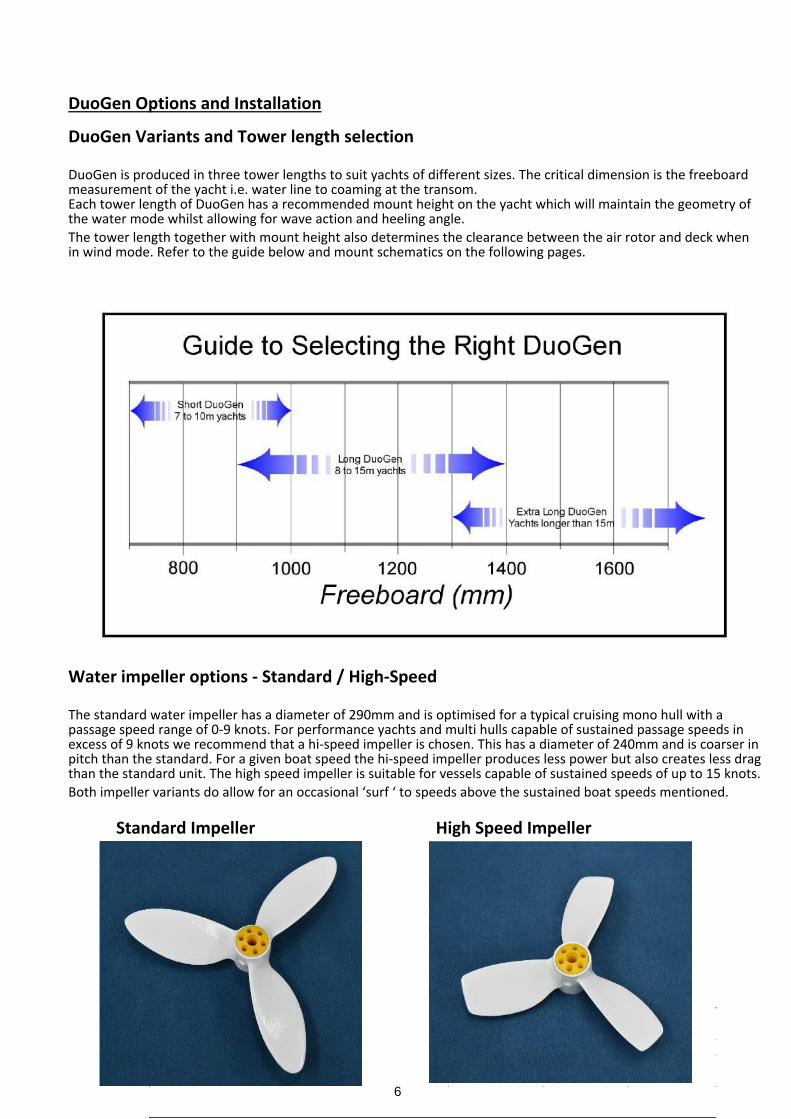
DuoGen is produced in three tower lengths to suit yachts of different sizes. The critical dimension is the freeboardmeasurement of the yacht i.e. water line to coaming at the transom.Each tower length of DuoGen has a recommended mount height on the yacht which will maintain the geometry ofthe water mode whilst allowing for wave action and heeling angle.The tower length together with mount height also determines the clearance between the air rotor and deck whenin wind mode. Refer to the guide below and mount schematics on the following pages.
Water impeller options - Standard / High-Speed
The standard water impeller has a diameter of 290mm and is optimised for a typical cruising mono hull with apassage speed range of 0-9 knots. For performance yachts and multi hulls capable of sustained passage speeds inexcess of 9 knots we recommend that a hi-speed impeller is chosen. This has a diameter of 240mm and is coarser inpitch than the standard. For a given boat speed the hi-speed impeller produces less power but also creates less dragthan the standard unit. The high speed impeller is suitable for vessels capable of sustained speeds of up to 15 knots.Both impeller variants do allow for an occasional ‘surf ‘ to speeds above the sustained boat speeds mentioned.
Standard Impeller High Speed Impeller
7
System Voltage
DuoGen is available in 12,24, and 48V variants. It is vital that the DuoGen is the same voltage as the yachtsprimary electrical system.
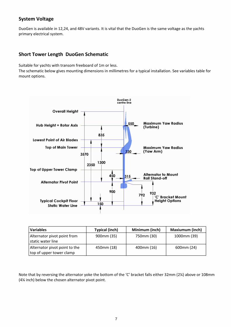
Short Tower Length DuoGen Schematic
Suitable for yachts with transom freeboard of 1m or less.The schematic below gives mounting dimensions in millimetres for a typical installation. See variables table formount options.
Note that by reversing the alternator yoke the bottom of the ‘C’ bracket falls either 32mm (2¼) above or 108mm(4¼ inch) below the chosen alternator pivot point.
Variables Typical (inch) Minimum (inch) Maxiumum (inch)Alternator pivot point fromstatic water line
900mm (35) 750mm (30) 1000mm (39)
Alternator pivot point to thetop of upper tower clamp
450mm (18) 400mm (16) 600mm (24)
8
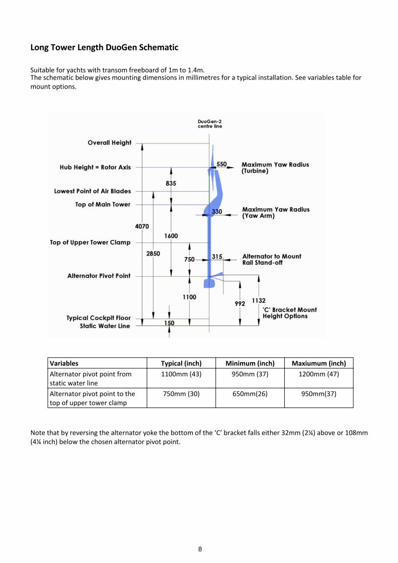
Long Tower Length DuoGen Schematic
Suitable for yachts with transom freeboard of 1m to 1.4m.The schematic below gives mounting dimensions in millimetres for a typical installation. See variables table formount options.
Note that by reversing the alternator yoke the bottom of the ‘C’ bracket falls either 32mm (2¼) above or 108mm(4¼ inch) below the chosen alternator pivot point.
Variables Typical (inch) Minimum (inch) Maxiumum (inch)Alternator pivot point fromstatic water line
1100mm (43) 950mm (37) 1200mm (47)
Alternator pivot point to thetop of upper tower clamp
750mm (30) 650mm(26) 950mm(37)
9
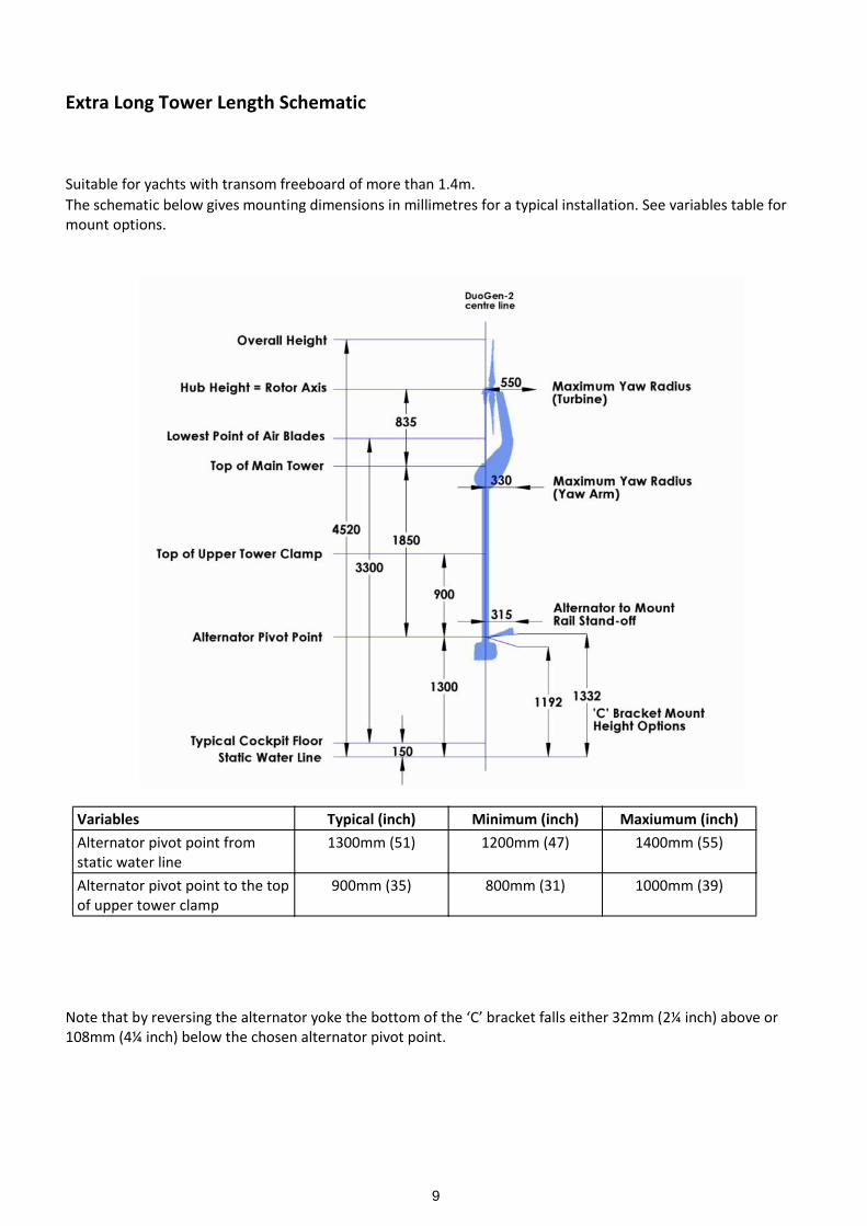
Extra Long Tower Length Schematic
Suitable for yachts with transom freeboard of more than 1.4m.The schematic below gives mounting dimensions in millimetres for a typical installation. See variables table formount options.
Note that by reversing the alternator yoke the bottom of the ‘C’ bracket falls either 32mm (2¼ inch) above or108mm (4¼ inch) below the chosen alternator pivot point.
Variables Typical (inch) Minimum (inch) Maxiumum (inch)Alternator pivot point fromstatic water line
1300mm (51) 1200mm (47) 1400mm (55)
Alternator pivot point to the topof upper tower clamp
900mm (35) 800mm (31) 1000mm (39)
10
Assembling your DuoGen
Congratulations on your purchase of the DuoGen-3 Water/Wind battery charging system.
For ease of handling, your DuoGen is supplied in four cartons, and requires preliminary assembly beforeinstallation on the yacht.
Unless you have access to a large workbench, we suggest you undertake the assembly on the floor, as the completedmachine will be around 2 metres long.Avoid assembling on a pontoon or a sloping deck as dropped fasteners can easily find their way into the water!Refer to the packing list in box B.
1. Unpack the box marked ‘A’. Check the identification label on the back to ensure the alternator is the correct voltage for your yacht’s system. Also, take a note of the alternator’s serial number and enter it into the instruction manual for future reference.2. Unpack the tubular carton ‘D’ and remove the main tower and drive shaft assembly.3. Unpack the carton marked ‘C’ and remove the yaw arm. This carton also contains the air blades and the long stainless steel universal mount bracket. (Refer to pages 16 and 17 of the User’s Manual to identify parts.)4. Take the yaw arm and ensure the spring plunger is in its withdrawn position by sliding the black actuating knob rearwards and rotating 180° clockwise to lock.5. Offer the yaw arm up to the bottom of the main tower tube (ie. the end opposite to the bearing) and slide the yaw arm onto the tower.6. Arrange the alternator such that the shaft is aligned with the tower. Pull the outer part of the telescopic drive shaft out of the bottom of the main tower. This exposes the flexible shaft coupler.7. Remove the lower M6 nut and bolt from the flexible shaft coupler and then slide the coupler onto the alternator drive shaft. Align the holes through the coupler and alternator shaft, and re-fit the M6 bolt and nut.8. Remove the two M8 tower cap screws and plastic washers from the base of the alternator nose. Apply Tef-Gel anti-seize compound to the machined aluminium surface at the base of the alternator nose. This will prevent corrosion and ease subsequent disassembly. Also, apply a little Tef-Gel to the tapped M8 holes.9. Slide the main tower onto the alternator nose. Note that as you do so the upper drive shaft sleeve needs to pass through the spherical bearing at the top of the tower. If the tower will not slide all the way onto the alternator nose, check the alignment of this bearing and get an assistant to ‘wobble’ the upper drive shaft to get it to enter the top bearing. Do not force it.10. Refit the drop nose pin lanyard and conical connector to the inner drive shaft with the M5 shoulder bolt provided.11. Align the alternator such that the cable gland is on the right hand side when viewed from the rear. Rotate the main tower tube such that the yaw arm lock hole at the top of the tower is orientated upwards. Refit the two M8 tower cap screws and plastic washers, having first smeared the threads with a little Tef-Gel. This will ease future disassembly.12. Finally, check the DuoGen by rotating the black conical connector on the upper drive shaft to ensure that the drive shafts rotate smoothly. Should the drive shaft bind, suspect the flexible coupler installation, and re-check for the correct fitting of the coupler bolt.
Subsequent assembly is covered in the Universal Mount Bracket Installation notes.- Page 12
11
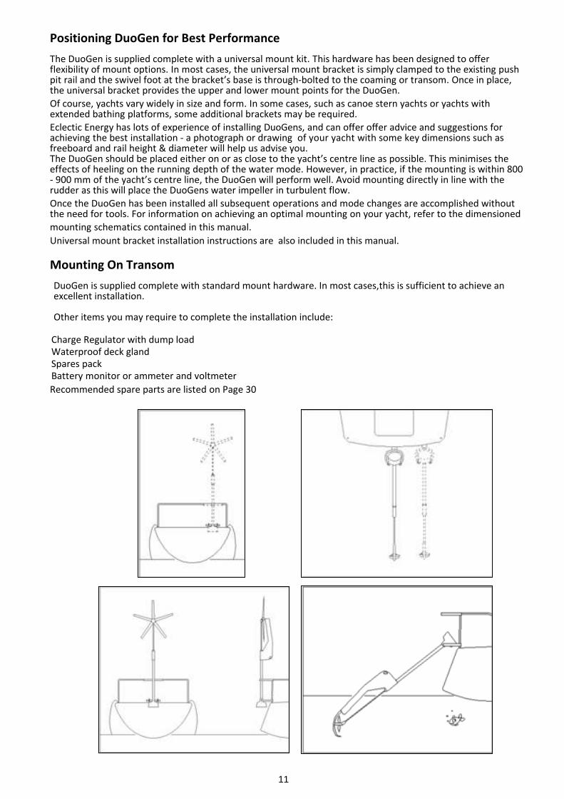
Positioning DuoGen for Best PerformanceThe DuoGen is supplied complete with a universal mount kit. This hardware has been designed to offerflexibility of mount options. In most cases, the universal mount bracket is simply clamped to the existing pushpit rail and the swivel foot at the bracket’s base is through-bolted to the coaming or transom. Once in place,the universal bracket provides the upper and lower mount points for the DuoGen.Of course, yachts vary widely in size and form. In some cases, such as canoe stern yachts or yachts withextended bathing platforms, some additional brackets may be required.Eclectic Energy has lots of experience of installing DuoGens, and can offer offer advice and suggestions forachieving the best installation - a photograph or drawing of your yacht with some key dimensions such asfreeboard and rail height & diameter will help us advise you.The DuoGen should be placed either on or as close to the yacht’s centre line as possible. This minimises theeffects of heeling on the running depth of the water mode. However, in practice, if the mounting is within 800- 900 mm of the yacht’s centre line, the DuoGen will perform well. Avoid mounting directly in line with therudder as this will place the DuoGens water impeller in turbulent flow.Once the DuoGen has been installed all subsequent operations and mode changes are accomplished withoutthe need for tools. For information on achieving an optimal mounting on your yacht, refer to the dimensionedmounting schematics contained in this manual.Universal mount bracket installation instructions are also included in this manual.
Mounting On TransomDuoGen is supplied complete with standard mount hardware. In most cases,this is sufficient to achieve anexcellent installation.
Other items you may require to complete the installation include:
Charge Regulator with dump loadWaterproof deck glandSpares packBattery monitor or ammeter and voltmeterRecommended spare parts are listed on Page 30
12
DuoGen Universal Mount Bracket Installation
1. Read all the instructions carefully before commencing installation and familiarise yourself withthe components.
2. Allow yourself plenty of time, at least four hours. Fitting DuoGen is not difficult, but it is unfamiliar, and rushing doesn't help! If you can enlist an assistant the job will be much easier.
3. There is nothing worse than dropping tools or fasteners overboard! It is usually well worth the effort of inflatingthe dinghy and securing it across the transom so you can tackle the job from both sides. Alternatively, bring theyacht in stern to so her transom can be reached from the pontoon.
4. You will see that, when installing using the universal bracket, the bracket becomes a new vertical push pitmember.
5. Consider the diagrams and photographs and decide how best the universal bracket can be attached to youryacht.
6. It is often useful to offer the bracket up to the rails in a variety of positions before beginning to attach it with thesupplied rail clamps. Note that some drilling and sawing operations may be required. The universal bracket ismade of 316 stainless steel and is very hard. Make sure you have a new high speed steel hacksaw blade availableand a new high speed steel 5 mm drill bit. It will save a lot of frustration!
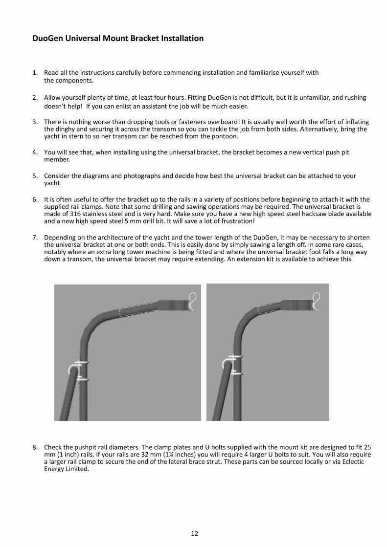
7. Depending on the architecture of the yacht and the tower length of the DuoGen, it may be necessary to shortenthe universal bracket at one or both ends. This is easily done by simply sawing a length off. In some rare cases,notably where an extra long tower machine is being fitted and where the universal bracket foot falls a long waydown a transom, the universal bracket may require extending. An extension kit is available to achieve this.
8. Check the pushpit rail diameters. The clamp plates and U bolts supplied with the mount kit are designed to fit 25mm (1 inch) rails. If your rails are 32 mm (1¼ inches) you will require 4 larger U bolts to suit. You will also requirea larger rail clamp to secure the end of the lateral brace strut. These parts can be sourced locally or via EclecticEnergy Limited.
13
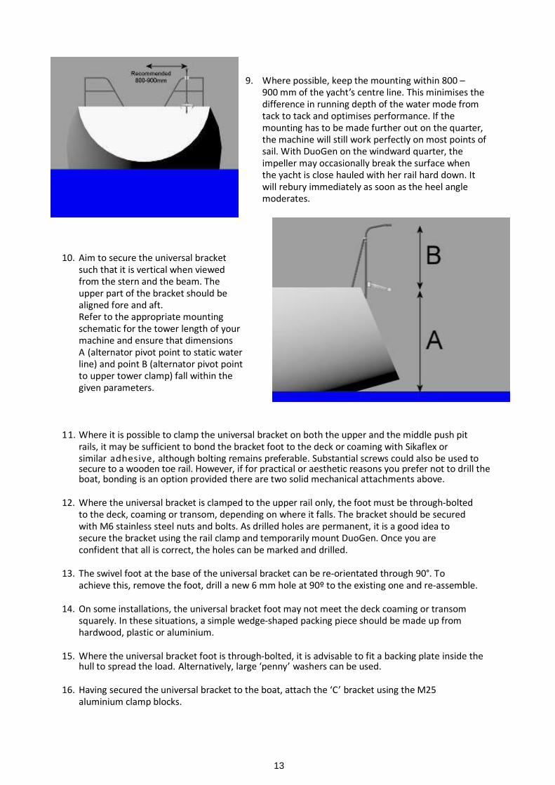
9. Where possible, keep the mounting within 800 –900 mm of the yacht’s centre line. This minimises thedifference in running depth of the water mode fromtack to tack and optimises performance. If themounting has to be made further out on the quarter,the machine will still work perfectly on most points ofsail. With DuoGen on the windward quarter, theimpeller may occasionally break the surface whenthe yacht is close hauled with her rail hard down. Itwill rebury immediately as soon as the heel anglemoderates.
10. Aim to secure the universal bracketsuch that it is vertical when viewedfrom the stern and the beam. Theupper part of the bracket should bealigned fore and aft.Refer to the appropriate mountingschematic for the tower length of yourmachine and ensure that dimensionsA (alternator pivot point to static waterline) and point B (alternator pivot pointto upper tower clamp) fall within thegiven parameters.
11. Where it is possible to clamp the universal bracket on both the upper and the middle push pitrails, it may be sufficient to bond the bracket foot to the deck or coaming with Sikaflex orsimilar adhesive, although bolting remains preferable. Substantial screws could also be used tosecure to a wooden toe rail. However, if for practical or aesthetic reasons you prefer not to drill theboat, bonding is an option provided there are two solid mechanical attachments above.
12. Where the universal bracket is clamped to the upper rail only, the foot must be through-boltedto the deck, coaming or transom, depending on where it falls. The bracket should be securedwith M6 stainless steel nuts and bolts. As drilled holes are permanent, it is a good idea tosecure the bracket using the rail clamp and temporarily mount DuoGen. Once you areconfident that all is correct, the holes can be marked and drilled.
13. The swivel foot at the base of the universal bracket can be re-orientated through 90°. Toachieve this, remove the foot, drill a new 6 mm hole at 90º to the existing one and re-assemble.
14. On some installations, the universal bracket foot may not meet the deck coaming or transomsquarely. In these situations, a simple wedge-shaped packing piece should be made up fromhardwood, plastic or aluminium.
15. Where the universal bracket foot is through-bolted, it is advisable to fit a backing plate inside thehull to spread the load. Alternatively, large ‘penny’ washers can be used.
16. Having secured the universal bracket to the boat, attach the ‘C’ bracket using the M25aluminium clamp blocks.
14
17. Temporarily fit the alternator yoke by installing the 10 mm hinge pin. Centralise the yoke andtighten the pivot lock mini wing screw. Measure the distance from the alternator pivot point tothe static water line. Slacken the clamp bolts slightly and slide the ‘C’ bracket up or down tobring the measurement within the parameters specified for the tower length of your machine.Note that the alternator yoke is reversible and that this has the effect of raising or lowering thepivot point. Ensure that the yoke is square to the yacht and the upper part of the universalbracket when viewed from aboard and tighten the clamp bolts.
18. Temporarily fit the upper tower clamp by sliding the 7/8 inch tube inside the upper part of theuniversal bracket. Take care to re-fit the rubber anti-rattle ring.
19. Enlist an assistant to help in mounting DuoGen using the short 10 mm pins, passing themthrough the bushes in the yoke. The machine is quite heavy and the holes need to beaccurately aligned for the pins to slide home. This is why the job is best undertaken with twopairs of hands.NOTE: when properly fitted, the alternator/ tower retaining screw and plunger hole at the top ofthe tower should be pointing forward towards the bows.
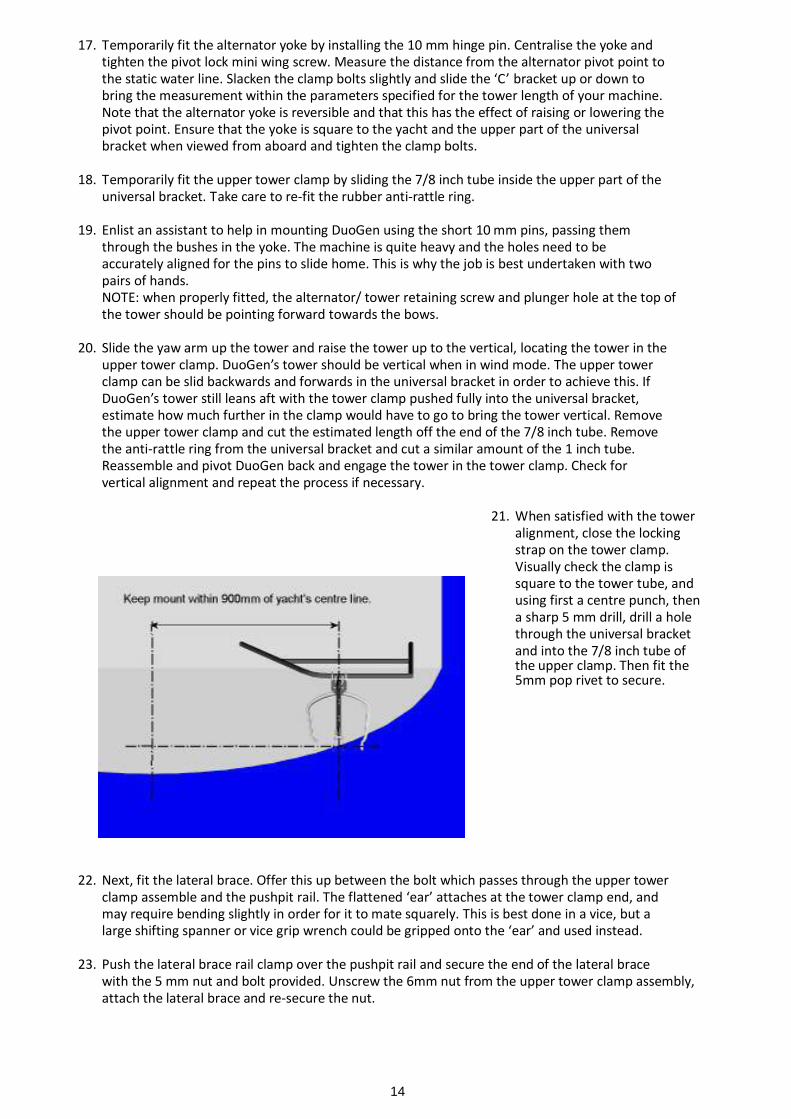
20. Slide the yaw arm up the tower and raise the tower up to the vertical, locating the tower in theupper tower clamp. DuoGen’s tower should be vertical when in wind mode. The upper towerclamp can be slid backwards and forwards in the universal bracket in order to achieve this. IfDuoGen’s tower still leans aft with the tower clamp pushed fully into the universal bracket,estimate how much further in the clamp would have to go to bring the tower vertical. Removethe upper tower clamp and cut the estimated length off the end of the 7/8 inch tube. Removethe anti-rattle ring from the universal bracket and cut a similar amount of the 1 inch tube.Reassemble and pivot DuoGen back and engage the tower in the tower clamp. Check forvertical alignment and repeat the process if necessary.
21. When satisfied with the toweralignment, close the lockingstrap on the tower clamp.Visually check the clamp issquare to the tower tube, andusing first a centre punch, thena sharp 5 mm drill, drill a holethrough the universal bracketand into the 7/8 inch tube ofthe upper clamp. Then fit the5mm pop rivet to secure.
22. Next, fit the lateral brace. Offer this up between the bolt which passes through the upper towerclamp assemble and the pushpit rail. The flattened ‘ear’ attaches at the tower clamp end, andmay require bending slightly in order for it to mate squarely. This is best done in a vice, but alarge shifting spanner or vice grip wrench could be gripped onto the ‘ear’ and used instead.
23. Push the lateral brace rail clamp over the pushpit rail and secure the end of the lateral bracewith the 5 mm nut and bolt provided. Unscrew the 6mm nut from the upper tower clamp assembly,attach the lateral brace and re-secure the nut.
15
24. Tighten all fasteners.
25. Check that DuoGen pivots freely from wind mode position to water mode. Release ‘C’ bracketpivot lock mini wing and ensure DuoGen pivots freely from side to side. Centralise thealternator yoke, re-tighten the ‘C’ bracket pivot lock. Raise DuoGen back to wind mode position.Ensure that the upper tower clamp strap closes properly .If it does not, or requires undue force to close it, re-check alignment.
26. Fit nut covers and Tower Lock warning sticker.
27. Decide where to bring the cable into the yacht and fit a deck gland. (Do not use deck plugs andsocket.) Allow a reasonable loop of free cable so that the cable is not strained as DuoGen pivotsbetween modes. Raise and lower the machine to make sure the cable is not pulled taut.
28. Make the electrical connections in accordance with the diagrams and guidelines in the manual, and ensureyou fit the in-line fuses. If in doubt, seek qualified assistance.
29. If at any point you experience difficulty or are unsure about how to proceed, contact us. We will do everything we can to assist you.
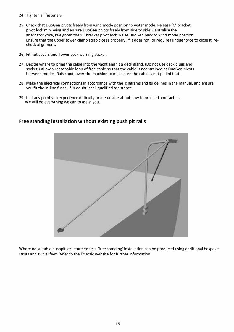
Free standing installation without existing push pit rails
Where no suitable pushpit structure exists a ‘free standing’ installation can be produced using additional bespokestruts and swivel feet. Refer to the Eclectic website for further information.
16
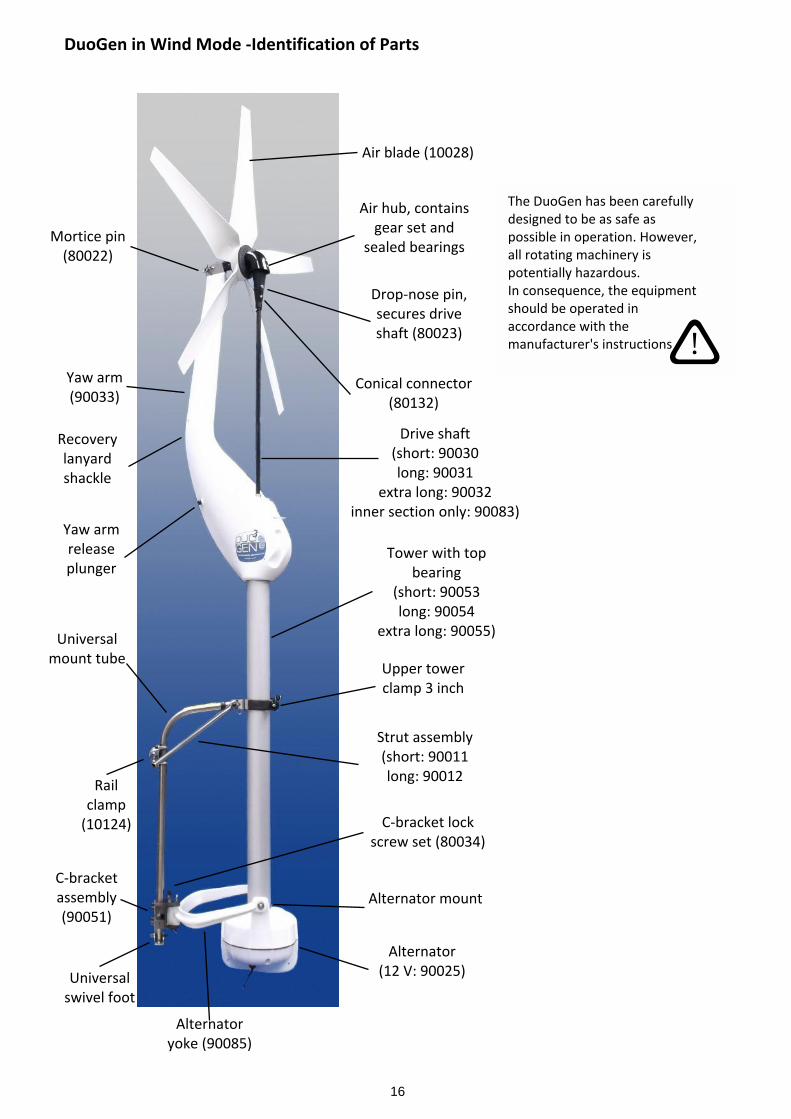
The DuoGen has been carefullydesigned to be as safe aspossible in operation. However,all rotating machinery ispotentially hazardous.In consequence, the equipmentshould be operated inaccordance with themanufacturer's instructions
Air blade (10028)
Air hub, containsgear set and
sealed bearingsMortice pin
(80022)
Drop-nose pin,secures driveshaft (80023)
Drive shaft(short: 90030long: 90031
extra long: 90032inner section only: 90083)
Yaw arm(90033)
Recoverylanyardshackle
Yaw armreleaseplunger
Tower with topbearing
(short: 90053long: 90054
extra long: 90055)
Upper towerclamp 3 inch
Railclamp
(10124)
Universalmount tube
Strut assembly(short: 90011long: 90012
Alternator mount
Alternator(12 V: 90025)
Alternatoryoke (90085)
C-bracket lockscrew set (80034)
C-bracketassembly(90051)
Universalswivel foot
Conical connector(80132)
ê!
DuoGen in Wind Mode -Identification of Parts
17
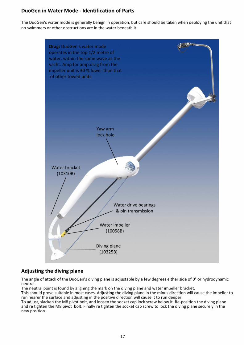
Diving plane(10325B)
Water bracket(10310B)
Yaw armlock hole
Water impeller(10058B)
Water drive bearings& pin transmission
Drag: DuoGen’s water modeoperates in the top 1/2 metre ofwater, within the same wave as theyacht. Amp for amp,drag from theimpeller unit is 30 % lower than that of other towed units.
DuoGen in Water Mode - Identification of Parts
The DuoGen's water mode is generally benign in operation, but care should be taken when deploying the unit thatno swimmers or other obstructions are in the water beneath it.
Adjusting the diving planeThe angle of attack of the DuoGen’s diving plane is adjustable by a few degrees either side of 0° or hydrodynamicneutral.The neutral point is found by aligning the mark on the diving plane and water impeller bracket.This should prove suitable in most cases. Adjusting the diving plane in the minus direction will cause the impeller torun nearer the surface and adjusting in the positive direction will cause it to run deeper.To adjust, slacken the M8 pivot bolt, and loosen the socket cap lock screw below it. Re-position the diving planeand re tighten the M8 pivot bolt. Finally re tighten the socket cap screw to lock the diving plane securely in thenew position.
18
Electrical Installation
As with the installation of all renewable energy equipment, the DuoGen wiring should be considered asessentially independent from the rest of the vessel’s electrical system.
Dedicated cables should be used to connect the DuoGen directly to the batteries via a dump type chargeregulator. The cables should not pass through the yachts main isolation switches.As DuoGen forms part of a low voltage system the owner can undertake the electrical installation him or her self.Be aware however that most faults associated with renewables on yachts are eventually traced to poor wiring orconnections. If you are unsure of your competence to do this work, it is best left to a professional marineelectrician.
The DuoGen is supplied with a 2 metre long output lead. This should be brought into the yacht via a propietarydeck gland, either at the deck or transom. Note we do not recommend the use of deck plugs and sockets. Theseconstiute a shock hazard should they become disconnected. Note also that any connectors used must be of asuitable rating. For a 12 volt DuoGen this should be at least 40A DC, and 20A DC for a 24 volt system.We reccomend a hardwired connection is made in the lazarette/ stern locker area between DuoGen output cableand the extension connecting cable which runs through to the regulator and batteries.
Wire Sizing
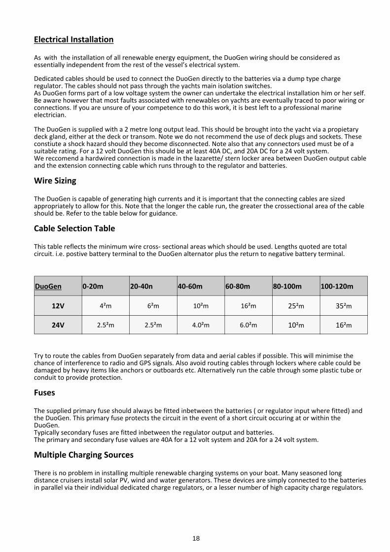
The DuoGen is capable of generating high currents and it is important that the connecting cables are sizedappropriately to allow for this. Note that the longer the cable run, the greater the crossectional area of the cableshould be. Refer to the table below for guidance.
Cable Selection Table
This table reflects the minimum wire cross- sectional areas which should be used. Lengths quoted are totalcircuit. i.e. postive battery terminal to the DuoGen alternator plus the return to negative battery terminal.
Try to route the cables from DuoGen separately from data and aerial cables if possible. This will minimise thechance of interference to radio and GPS signals. Also avoid routing cables through lockers where cable could bedamaged by heavy items like anchors or outboards etc. Alternatively run the cable through some plastic tube orconduit to provide protection.
Fuses
The supplied primary fuse should always be fitted inbetween the batteries ( or regulator input where fitted) andthe DuoGen. This primary fuse protects the circuit in the event of a short circuit occuring at or within theDuoGen.Typically secondary fuses are fitted inbetween the regulator output and batteries.The primary and secondary fuse values are 40A for a 12 volt system and 20A for a 24 volt system.
Multiple Charging Sources
There is no problem in installing multiple renewable charging systems on your boat. Many seasoned longdistance cruisers install solar PV, wind and water generators. These devices are simply connected to the batteriesin parallel via their individual dedicated charge regulators, or a lesser number of high capacity charge regulators.
DuoGen 0-20m 20-40n 40-60m 60-80m 80-100m 100-120m
12V 4²m 6²m 10²m 16²m 25²m 35²m
24V 2.5²m 2.5²m 4.0²m 6.0²m 10²m 16²m
19
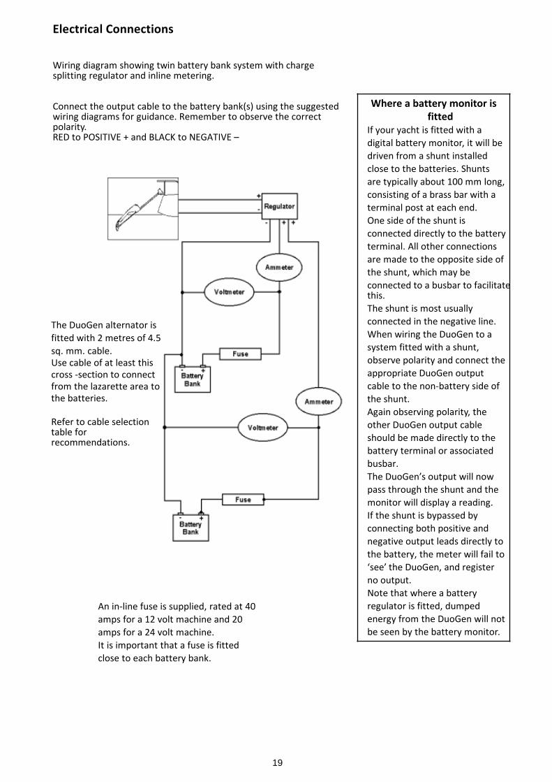
The DuoGen alternator isfitted with 2 metres of 4.5sq. mm. cable.Use cable of at least thiscross -section to connectfrom the lazarette area tothe batteries.
Refer to cable selectiontable forrecommendations.
An in-line fuse is supplied, rated at 40amps for a 12 volt machine and 20amps for a 24 volt machine.It is important that a fuse is fittedclose to each battery bank.
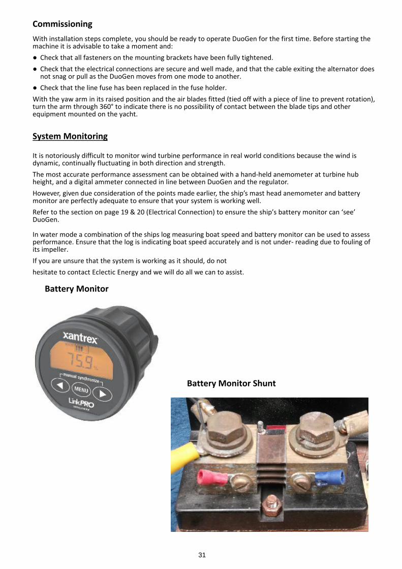
Where a battery monitor isfitted
If your yacht is fitted with adigital battery monitor, it will bedriven from a shunt installedclose to the batteries. Shuntsare typically about 100 mm long,consisting of a brass bar with aterminal post at each end.One side of the shunt isconnected directly to the batteryterminal. All other connectionsare made to the opposite side ofthe shunt, which may beconnected to a busbar to facilitatethis.The shunt is most usuallyconnected in the negative line.When wiring the DuoGen to asystem fitted with a shunt,observe polarity and connect theappropriate DuoGen outputcable to the non-battery side ofthe shunt.Again observing polarity, theother DuoGen output cableshould be made directly to thebattery terminal or associatedbusbar.The DuoGen’s output will nowpass through the shunt and themonitor will display a reading.If the shunt is bypassed byconnecting both positive andnegative output leads directly tothe battery, the meter will fail to‘see’ the DuoGen, and registerno output.Note that where a batteryregulator is fitted, dumpedenergy from the DuoGen will notbe seen by the battery monitor.
Electrical Connections
Wiring diagram showing twin battery bank system with chargesplitting regulator and inline metering.
Connect the output cable to the battery bank(s) using the suggestedwiring diagrams for guidance. Remember to observe the correctpolarity.RED to POSITIVE + and BLACK to NEGATIVE –
20
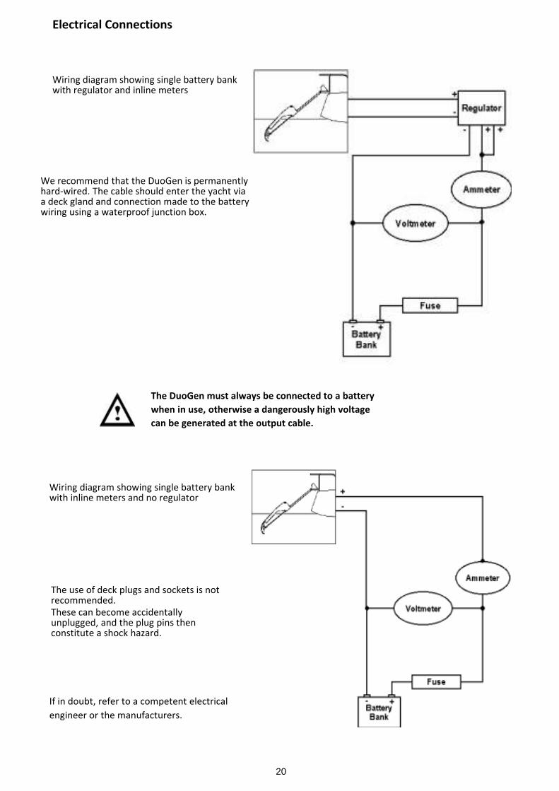
The DuoGen must always be connected to a batterywhen in use, otherwise a dangerously high voltagecan be generated at the output cable.
If in doubt, refer to a competent electricalengineer or the manufacturers.
Wiring diagram showing single battery bankwith inline meters and no regulator
Electrical Connections
Wiring diagram showing single battery bankwith regulator and inline meters
We recommend that the DuoGen is permanentlyhard-wired. The cable should enter the yacht viaa deck gland and connection made to the batterywiring using a waterproof junction box.
The use of deck plugs and sockets is notrecommended.These can become accidentallyunplugged, and the plug pins thenconstitute a shock hazard.
21
Charge Regulation
Battery Protection
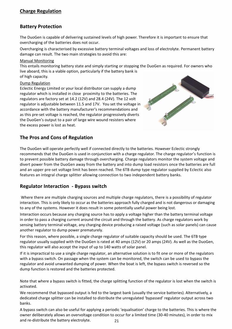
The DuoGen is capable of delivering sustained levels of high power. Therefore it is important to ensure thatovercharging of the batteries does not occur.Overcharging is characterised by excessive battery terminal voltages and loss of electrolyte. Permanent batterydamage can result. The two main strategies to avoid this are:Manual MonitoringThis entails monitoring battery state and simply starting or stopping the DuoGen as required. For owners wholive aboard, this is a viable option, particularly if the battery bank isof high capacity.Dump RegulationEclectic Energy Limited or your local distributor can supply a dumpregulator which is installed in close proximity to the batteries. Theregulators are factory set at 14.2 (12V) and 28.4 (24V). The 12 voltregulator is adjustable between 11.5 and 17V. You set the voltage inaccordance with the battery manufacturer's recommendations andas this pre-set voltage is reached, the regulator progressively divertsthe DuoGen’s output to a pair of large wire wound resisters wherethe excess power is lost as heat.
The Pros and Cons of Regulation
The DuoGen will operate perfectly well if connected directly to the batteries. However Eclectic stronglyrecommends that the DuoGen is used in conjunction with a charge regulator. The charge regulator’s function isto prevent possible battery damage through overcharging. Charge regulators monitor the system voltage anddivert power from the DuoGen away from the battery and into dump load resistors once the batteries are fulland an upper pre-set voltage limit has been reached. The 6TB dump type regulator supplied by Eclectic alsofeatures an integral charge splitter allowing connection to two independent battery banks.
Regulator Interaction - Bypass switch
Where there are multiple charging sources and multiple charge regulators, there is a possibility of regulatorinteraction. This is only likely to occur as the batteries approach fully charged and is not dangerous or damagingto any of the systems. However it does result in some potentially useful power being lost.Interaction occurs because any charging source has to apply a voltage higher than the battery terminal voltagein order to pass a charging current around the circuit and through the battery. As charge regulators work bysensing battery terminal voltage, any charging device producing a raised voltage (such as solar panels) can causeanother regulator to dump power prematurely.For this reason, where possible, a single charge regulator of suitable capacity should be used. The 6TB typeregulator usually supplied with the DuoGen is rated at 40 amps (12V) or 20 amps (24V). As well as the DuoGen,this regulator will also accept the input of up to 140 watts of solar panel.If it is impractical to use a single charge regulator, an alternative solution is to fit one or more of the regulatorswith a bypass switch. On passage when the system can be monitored, the switch can be used to bypass theregulator and avoid unwanted dumping of power. When the boat is left, the bypass switch is reversed so thedump function is restored and the batteries protected.
Note that where a bypass switch is fitted, the charge splitting function of the regulator is lost when the switch isactivated.We recommend that bypassed output is fed to the largest bank (usually the service batteries). Alternatively, adedicated charge splitter can be installed to distribute the unregulated ‘bypassed’ regulator output across twobanks.A bypass switch can also be useful for applying a periodic ‘equalisation’ charge to the batteries. This is where theowner deliberately allows an overvoltage condition to occur for a limited time (30-40 minutes), in order to mixand re-distribute the battery electrolyte.
22
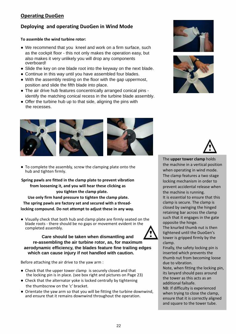
The upper tower clamp holdsthe machine in a vertical positionwhen operating in wind mode.The clamp features a two stagelocking mechanism in order toprevent accidental release whenthe machine is running.It is essential to ensure that thisclamp is secure. The clamp isclosed by swinging the hingedretaining bar across the clampsuch that it engages in the gateopposite the hinge.The knurled thumb nut is thentightened until the DuoGen’stower is gripped firmly by theclamp.Finally, the safety locking pin isinserted which prevents thethumb nut from becoming loosedue to vibration.Note, when fitting the locking pin,its lanyard should pass aroundthe tower as this acts as anadditional failsafe.NB: If difficulty is experiencedwhen trying to close the clamp,ensure that it is correctly alignedand square to the tower tube.
Operating DuoGen
Deploying and operating DuoGen in Wind Mode
To assemble the wind turbine rotor:
● We recommend that you kneel and work on a firm surface, suchas the cockpit floor - this not only makes the operation easy, butalso makes it very unlikely you will drop any componentsoverboard!
● Slide the key on one blade root into the keyway on the next blade.● Continue in this way until you have assembled four blades.● With the assembly resting on the floor with the gap uppermost,
position and slide the fifth blade into place.● The air drive hub features concentrically arranged conical pins -
identify the matching conical recess in the turbine blade assembly.● Offer the turbine hub up to that side, aligning the pins with the recesses.
● To complete the assembly, screw the clamping plate onto thehub and tighten firmly.
Spring pawls are fitted in the clamp plate to prevent vibrationfrom loosening it, and you will hear these clicking as
you tighten the clamp plate.Use only firm hand pressure to tighten the clamp plate.
The spring pawls are factory set and secured with a thread-locking compound. Do not attempt to adjust these in any way.
● Visually check that both hub and clamp plate are firmly seated on theblade roots - there should be no gaps or movement evident in thecompleted assembly.
Care should be taken when dismantling andre-assembling the air turbine rotor, as, for maximum
aerodynamic efficiency, the blades feature fine trailing edgeswhich can cause injury if not handled with caution.
Before attaching the air drive to the yaw arm :
● Check that the upper tower clamp is securely closed and that the locking pin is in place. (see box right and pictures on Page 23)
● Check that the alternator yoke is locked centrally by tightening the thumbscrew on the ‘c’ bracket.
● Orientate the yaw arm so that you will be fitting the turbine downwind,and ensure that it remains downwind throughout the operation.
23
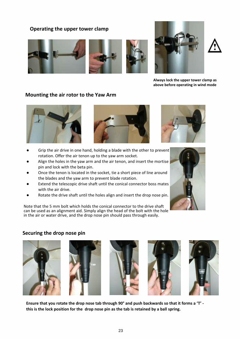
● Grip the air drive in one hand, holding a blade with the other to preventrotation. Offer the air tenon up to the yaw arm socket.
● Align the holes in the yaw arm and the air tenon, and insert the mortisepin and lock with the beta pin.
● Once the tenon is located in the socket, tie a short piece of line aroundthe blades and the yaw arm to prevent blade rotation.
● Extend the telescopic drive shaft until the conical connector boss mateswith the air drive.
● Rotate the drive shaft until the holes align and insert the drop nose pin.
Note that the 5 mm bolt which holds the conical connector to the drive shaftcan be used as an alignment aid. Simply align the head of the bolt with the holein the air or water drive, and the drop nose pin should pass through easily.
Ensure that you rotate the drop nose tab through 90° and push backwards so that it forms a ‘T’ -this is the lock position for the drop nose pin as the tab is retained by a ball spring.
Always lock the upper tower clamp asabove before operating in wind mode
Operating the upper tower clamp
Securing the drop nose pin
Mounting the air rotor to the Yaw Arm
24
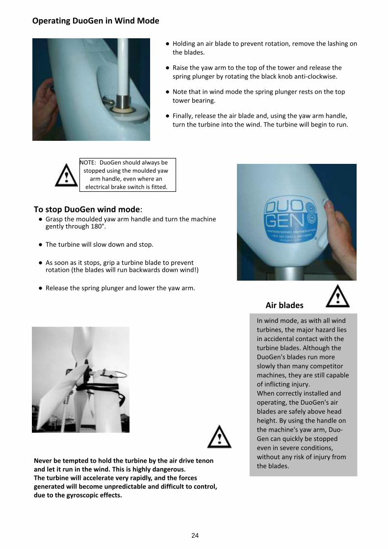
In wind mode, as with all windturbines, the major hazard liesin accidental contact with theturbine blades. Although theDuoGen's blades run moreslowly than many competitormachines, they are still capableof inflicting injury.When correctly installed andoperating, the DuoGen's airblades are safely above headheight. By using the handle onthe machine's yaw arm, Duo-Gen can quickly be stoppedeven in severe conditions,without any risk of injury fromthe blades.
To stop DuoGen wind mode:● Grasp the moulded yaw arm handle and turn the machine
gently through 180°.
● The turbine will slow down and stop.
● As soon as it stops, grip a turbine blade to preventrotation (the blades will run backwards down wind!)
● Release the spring plunger and lower the yaw arm.
NOTE: DuoGen should always bestopped using the moulded yaw
arm handle, even where anelectrical brake switch is fitted.
Air blades
Never be tempted to hold the turbine by the air drive tenonand let it run in the wind. This is highly dangerous.The turbine will accelerate very rapidly, and the forcesgenerated will become unpredictable and difficult to control,due to the gyroscopic effects.
● Holding an air blade to prevent rotation, remove the lashing onthe blades.
● Raise the yaw arm to the top of the tower and release thespring plunger by rotating the black knob anti-clockwise.
● Note that in wind mode the spring plunger rests on the toptower bearing.
● Finally, release the air blade and, using the yaw arm handle,turn the turbine into the wind. The turbine will begin to run.
Operating DuoGen in Wind Mode
25
Normal DuoGen wind mode operation incorporating self furling
The self furling can be viewed as analogous to a yacht heeling to gusts of wind.In light breezes, the DuoGen’s air rotor will point almost directly at the wind. As the wind speed increases, it willbegin to furl about the main tower pointing progressively off the wind.Once a gust has passed, the air rotor will move back more closely to the wind direction.The effect of this furling action is to progressively reduce the intercept area of the air rotor in response to rising windspeeds, in much the same way that heeling reduces the effective sail area on the yacht.
High electrical outputs are maintained, but the wind loading on the DuoGen, its mounting and ultimately the yacht’smoorings, are controlled. In moderate breezes, the rotor may sit 5° to 10° off the wind, and in high winds 20° to 30°In practice, you will observe the DuoGen furling gently as a heavy gust of wind strikes, and then returning to itsoriginal position as the gust passes.
The furling force is provided by the alternator’s reluctance to be accelerated. This furling force is balanced by thewind loading on the air turbine rotor, and also DuoGen’s yaw arm, which acts like a tail.
In certain conditions, excessive or erratic furling may be observed. Probable causes are:
a) The operation of the regulator - as the regulator starts to dump power, the alternator suddenly becomes ‘stiffer’to turn and this produces a large increase in the furling force.
b) Turbulent air - as the furling force is balanced primarily by the wind loading on the rotor disc, turbulence andsudden ‘holes’ in the wind can result in an excessive and erratic furling action. Such turbulence is usually caused byobstructions upwind or down wind of the turbine, and are particular to a certain location and wind direction.
c) Mechanical or electrical fault - usually indicated by low or no electrical output, and/or undue mechanical frictionand noise.
d) Stiffness in the yaw bearing - usually caused by dirt or salt on the bearing surfaces. The yaw bearings are of a dryrunning plastic type, designed to run on anodised aluminium. Periodic flushing with fresh water and polishing thetower tube with a silicone-based furniture polish should restore free movement.
Disabling the furling to increase power output.
When lying at anchor with the wind mode deployed, the furling action can be disabled by inserting the yaw armspring plunger into the 10 mm hole at the top of the main tower. This locks the yaw arm with the air rotor facingdirectly towards the bows. The yacht herself now keeps the air rotor pointing at the wind, and power outputs for agiven wind speed will generally be higher.A similar effect can be achieved by restraining the yaw arm with shock cord or a lashing.
We recommend that you restore the furling action if the wind speed exceeds 25 knots or if you leave the boat.
26
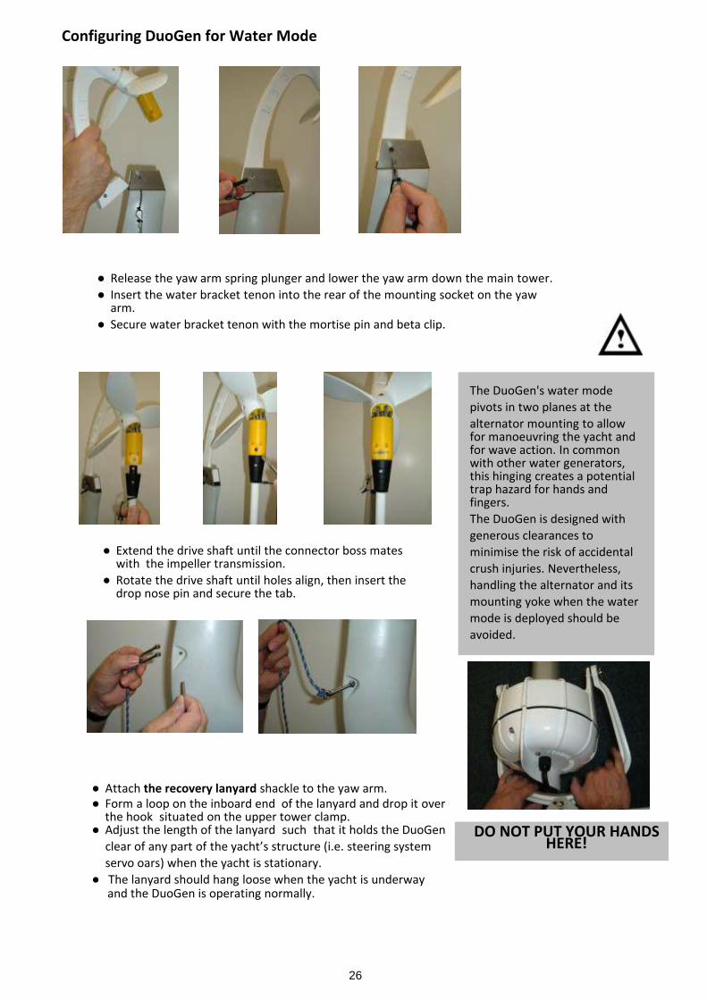
● Release the yaw arm spring plunger and lower the yaw arm down the main tower.● Insert the water bracket tenon into the rear of the mounting socket on the yaw
arm.● Secure water bracket tenon with the mortise pin and beta clip.
● Extend the drive shaft until the connector boss mateswith the impeller transmission.
● Rotate the drive shaft until holes align, then insert thedrop nose pin and secure the tab.
The DuoGen's water modepivots in two planes at thealternator mounting to allowfor manoeuvring the yacht andfor wave action. In commonwith other water generators,this hinging creates a potentialtrap hazard for hands andfingers.The DuoGen is designed withgenerous clearances tominimise the risk of accidentalcrush injuries. Nevertheless,handling the alternator and itsmounting yoke when the watermode is deployed should beavoided.
DO NOT PUT YOUR HANDSHERE!
Configuring DuoGen for Water Mode
● Attach the recovery lanyard shackle to the yaw arm.● Form a loop on the inboard end of the lanyard and drop it over
the hook situated on the upper tower clamp.● Adjust the length of the lanyard such that it holds the DuoGen clear of any part of the yacht’s structure (i.e. steering system servo oars) when the yacht is stationary.● The lanyard should hang loose when the yacht is underway
and the DuoGen is operating normally.
27
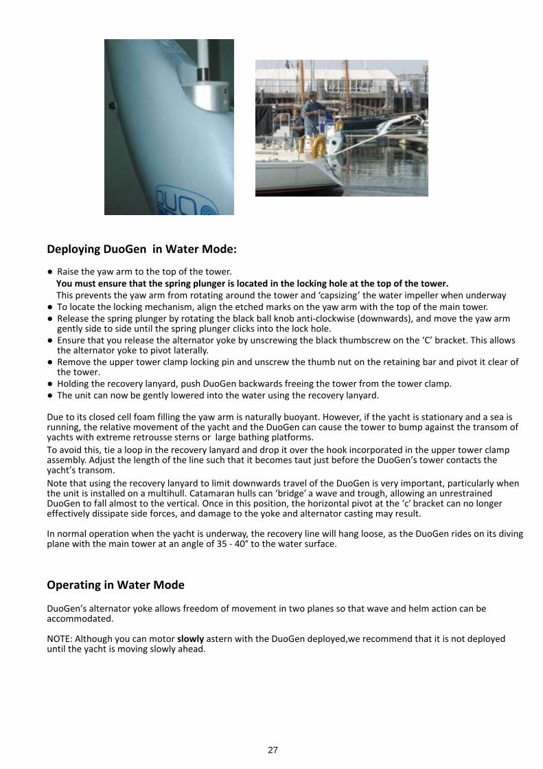
Deploying DuoGen in Water Mode:
● Raise the yaw arm to the top of the tower. You must ensure that the spring plunger is located in the locking hole at the top of the tower. This prevents the yaw arm from rotating around the tower and ‘capsizing’ the water impeller when underway● To locate the locking mechanism, align the etched marks on the yaw arm with the top of the main tower.● Release the spring plunger by rotating the black ball knob anti-clockwise (downwards), and move the yaw arm
gently side to side until the spring plunger clicks into the lock hole.● Ensure that you release the alternator yoke by unscrewing the black thumbscrew on the ‘C’ bracket. This allows
the alternator yoke to pivot laterally.● Remove the upper tower clamp locking pin and unscrew the thumb nut on the retaining bar and pivot it clear of
the tower.● Holding the recovery lanyard, push DuoGen backwards freeing the tower from the tower clamp.● The unit can now be gently lowered into the water using the recovery lanyard.
Due to its closed cell foam filling the yaw arm is naturally buoyant. However, if the yacht is stationary and a sea isrunning, the relative movement of the yacht and the DuoGen can cause the tower to bump against the transom ofyachts with extreme retrousse sterns or large bathing platforms.To avoid this, tie a loop in the recovery lanyard and drop it over the hook incorporated in the upper tower clampassembly. Adjust the length of the line such that it becomes taut just before the DuoGen’s tower contacts theyacht’s transom.Note that using the recovery lanyard to limit downwards travel of the DuoGen is very important, particularly whenthe unit is installed on a multihull. Catamaran hulls can ‘bridge’ a wave and trough, allowing an unrestrainedDuoGen to fall almost to the vertical. Once in this position, the horizontal pivot at the ‘c’ bracket can no longereffectively dissipate side forces, and damage to the yoke and alternator casting may result.
In normal operation when the yacht is underway, the recovery line will hang loose, as the DuoGen rides on its divingplane with the main tower at an angle of 35 - 40° to the water surface.
Operating in Water Mode
DuoGen’s alternator yoke allows freedom of movement in two planes so that wave and helm action can beaccommodated.
NOTE: Although you can motor slowly astern with the DuoGen deployed,we recommend that it is not deployeduntil the yacht is moving slowly ahead.
28
A clearing line can be rigged if weed or debris clogging the impeller is a problem.This is accomplished by using a piece of 3 mm pre-stretched line, secured by a stopper knot through the hole inthe diving plane with the other end made fast to the shackle above the moulded handle recess in the yaw arm.Alternatively, clearing lines can be secured to a loop of line attached to one of the holes in the alternator backplate fin. This option also allows the clearing line to be used to assist recovery of the DuoGen without reducingboat speed. (See section on recovering DuoGen)
Two additional holes are provided at the tips of the diving plane and further clearing lines can be passed throughthese to provide even more protection against floating debris.
Recovering The DuoGen Water Mode
To recover the DuoGen from water mode with the yacht stopped or moving slow ahead:
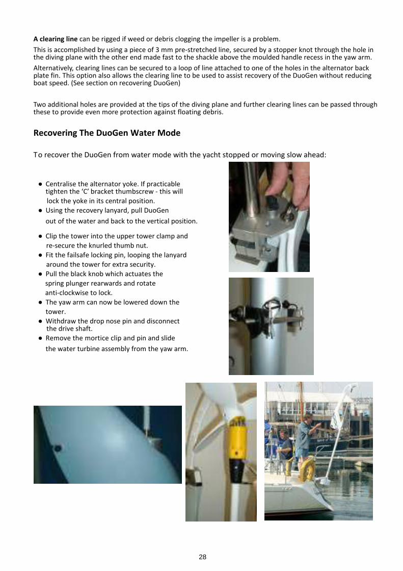
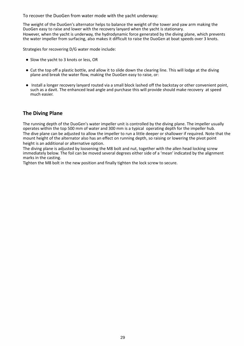
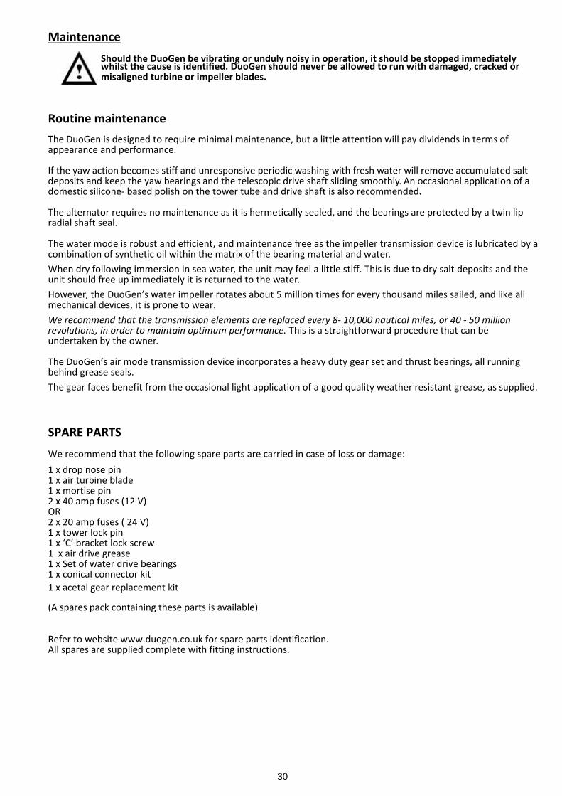
● Centralise the alternator yoke. If practicabletighten the ‘C’ bracket thumbscrew - this will
lock the yoke in its central position.● Using the recovery lanyard, pull DuoGen
out of the water and back to the vertical position.
● Clip the tower into the upper tower clamp and re-secure the knurled thumb nut.● Fit the failsafe locking pin, looping the lanyard around the tower for extra security.● Pull the black knob which actuates the spring plunger rearwards and rotate anti-clockwise to lock.● The yaw arm can now be lowered down the
tower.● Withdraw the drop nose pin and disconnect the drive shaft.● Remove the mortice clip and pin and slide
the water turbine assembly from the yaw arm.
29
To recover the DuoGen from water mode with the yacht underway:
The weight of the DuoGen’s alternator helps to balance the weight of the tower and yaw arm making theDuoGen easy to raise and lower with the recovery lanyard when the yacht is stationary.However, when the yacht is underway, the hydrodynamic force generated by the diving plane, which preventsthe water impeller from surfacing, also makes it difficult to raise the DuoGen at boat speeds over 3 knots.
Strategies for recovering D/G water mode include:
● Slow the yacht to 3 knots or less, OR
● Cut the top off a plastic bottle, and allow it to slide down the clearing line. This will lodge at the divingplane and break the water flow, making the DuoGen easy to raise, or:
● Install a longer recovery lanyard routed via a small block lashed off the backstay or other convenient point,such as a davit. The enhanced lead angle and purchase this will provide should make recovery at speedmuch easier.
The Diving Plane
The running depth of the DuoGen’s water impeller unit is controlled by the diving plane. The impeller usuallyoperates within the top 500 mm of water and 300 mm is a typical operating depth for the impeller hub.The dive plane can be adjusted to allow the impeller to run a little deeper or shallower if required. Note that themount height of the alternator also has an effect on running depth, so raising or lowering the pivot pointheight is an additional or alternative option.The diving plane is adjusted by loosening the M8 bolt and nut, together with the allen head locking screwimmediately below. The foil can be moved several degrees either side of a ‘mean’ indicated by the alignmentmarks in the casting.Tighten the M8 bolt in the new position and finally tighten the lock screw to secure.
30
MaintenanceShould the DuoGen be vibrating or unduly noisy in operation, it should be stopped immediatelywhilst the cause is identified. DuoGen should never be allowed to run with damaged, cracked ormisaligned turbine or impeller blades.
Routine maintenanceThe DuoGen is designed to require minimal maintenance, but a little attention will pay dividends in terms ofappearance and performance.
If the yaw action becomes stiff and unresponsive periodic washing with fresh water will remove accumulated saltdeposits and keep the yaw bearings and the telescopic drive shaft sliding smoothly. An occasional application of adomestic silicone- based polish on the tower tube and drive shaft is also recommended.
The alternator requires no maintenance as it is hermetically sealed, and the bearings are protected by a twin lipradial shaft seal.
The water mode is robust and efficient, and maintenance free as the impeller transmission device is lubricated by acombination of synthetic oil within the matrix of the bearing material and water.When dry following immersion in sea water, the unit may feel a little stiff. This is due to dry salt deposits and theunit should free up immediately it is returned to the water.However, the DuoGen’s water impeller rotates about 5 million times for every thousand miles sailed, and like allmechanical devices, it is prone to wear.We recommend that the transmission elements are replaced every 8- 10,000 nautical miles, or 40 - 50 millionrevolutions, in order to maintain optimum performance. This is a straightforward procedure that can beundertaken by the owner.
The DuoGen’s air mode transmission device incorporates a heavy duty gear set and thrust bearings, all runningbehind grease seals.The gear faces benefit from the occasional light application of a good quality weather resistant grease, as supplied.
SPARE PARTSWe recommend that the following spare parts are carried in case of loss or damage:1 x drop nose pin1 x air turbine blade1 x mortise pin2 x 40 amp fuses (12 V)OR2 x 20 amp fuses ( 24 V)1 x tower lock pin1 x ‘C’ bracket lock screw1 x air drive grease1 x Set of water drive bearings1 x conical connector kit1 x acetal gear replacement kit
(A spares pack containing these parts is available)
Refer to website www.duogen.co.uk for spare parts identification.All spares are supplied complete with fitting instructions.
31
CommissioningWith installation steps complete, you should be ready to operate DuoGen for the first time. Before starting themachine it is advisable to take a moment and:● Check that all fasteners on the mounting brackets have been fully tightened.● Check that the electrical connections are secure and well made, and that the cable exiting the alternator does
not snag or pull as the DuoGen moves from one mode to another.● Check that the line fuse has been replaced in the fuse holder.With the yaw arm in its raised position and the air blades fitted (tied off with a piece of line to prevent rotation),turn the arm through 360° to indicate there is no possibility of contact between the blade tips and otherequipment mounted on the yacht.
System Monitoring
It is notoriously difficult to monitor wind turbine performance in real world conditions because the wind isdynamic, continually fluctuating in both direction and strength.The most accurate performance assessment can be obtained with a hand-held anemometer at turbine hubheight, and a digital ammeter connected in line between DuoGen and the regulator.However, given due consideration of the points made earlier, the ship’s mast head anemometer and batterymonitor are perfectly adequate to ensure that your system is working well.Refer to the section on page 19 & 20 (Electrical Connection) to ensure the ship’s battery monitor can ‘see’DuoGen.
In water mode a combination of the ships log measuring boat speed and battery monitor can be used to assessperformance. Ensure that the log is indicating boat speed accurately and is not under- reading due to fouling ofits impeller.If you are unsure that the system is working as it should, do nothesitate to contact Eclectic Energy and we will do all we can to assist.
Battery Monitor
Battery Monitor Shunt
32
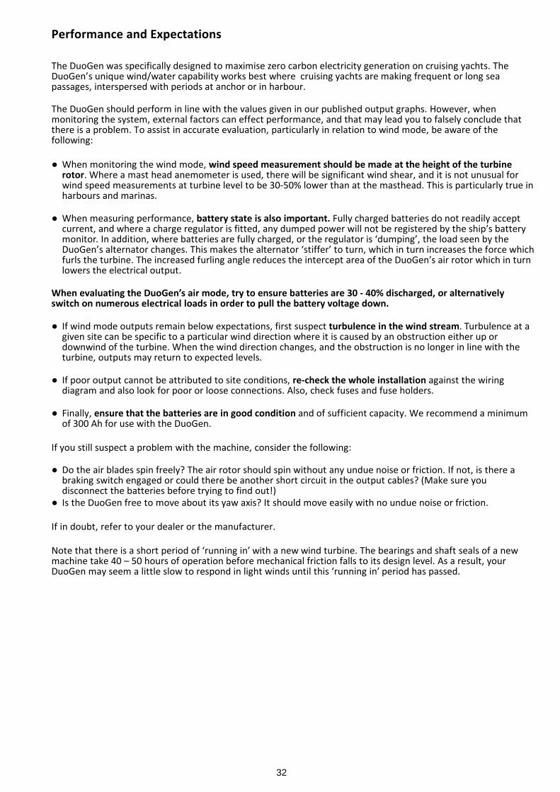
Performance and Expectations
The DuoGen was specifically designed to maximise zero carbon electricity generation on cruising yachts. TheDuoGen’s unique wind/water capability works best where cruising yachts are making frequent or long seapassages, interspersed with periods at anchor or in harbour.
The DuoGen should perform in line with the values given in our published output graphs. However, whenmonitoring the system, external factors can effect performance, and that may lead you to falsely conclude thatthere is a problem. To assist in accurate evaluation, particularly in relation to wind mode, be aware of thefollowing:
● When monitoring the wind mode, wind speed measurement should be made at the height of the turbinerotor. Where a mast head anemometer is used, there will be significant wind shear, and it is not unusual forwind speed measurements at turbine level to be 30-50% lower than at the masthead. This is particularly true inharbours and marinas.
● When measuring performance, battery state is also important. Fully charged batteries do not readily acceptcurrent, and where a charge regulator is fitted, any dumped power will not be registered by the ship’s batterymonitor. In addition, where batteries are fully charged, or the regulator is ‘dumping’, the load seen by theDuoGen’s alternator changes. This makes the alternator ‘stiffer’ to turn, which in turn increases the force whichfurls the turbine. The increased furling angle reduces the intercept area of the DuoGen’s air rotor which in turnlowers the electrical output.
When evaluating the DuoGen’s air mode, try to ensure batteries are 30 - 40% discharged, or alternativelyswitch on numerous electrical loads in order to pull the battery voltage down.
● If wind mode outputs remain below expectations, first suspect turbulence in the wind stream. Turbulence at agiven site can be specific to a particular wind direction where it is caused by an obstruction either up ordownwind of the turbine. When the wind direction changes, and the obstruction is no longer in line with theturbine, outputs may return to expected levels.
● If poor output cannot be attributed to site conditions, re-check the whole installation against the wiringdiagram and also look for poor or loose connections. Also, check fuses and fuse holders.
● Finally, ensure that the batteries are in good condition and of sufficient capacity. We recommend a minimumof 300 Ah for use with the DuoGen.
If you still suspect a problem with the machine, consider the following:
● Do the air blades spin freely? The air rotor should spin without any undue noise or friction. If not, is there abraking switch engaged or could there be another short circuit in the output cables? (Make sure youdisconnect the batteries before trying to find out!)
● Is the DuoGen free to move about its yaw axis? It should move easily with no undue noise or friction.
If in doubt, refer to your dealer or the manufacturer.
Note that there is a short period of ‘running in’ with a new wind turbine. The bearings and shaft seals of a newmachine take 40 – 50 hours of operation before mechanical friction falls to its design level. As a result, yourDuoGen may seem a little slow to respond in light winds until this ‘running in’ period has passed.
33
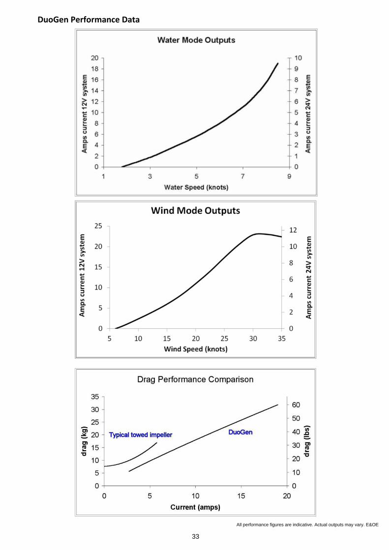
All performance figures are indicative. Actual outputs may vary. E&OE
DuoGen Performance Data
34
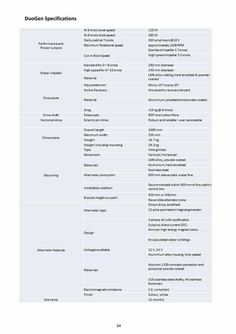
DuoGen Specifications
35
DuoGen Trouble Shooting and Diagnosing Problems
Noise and Vibration in Air ModeThe DuoGen has been carefully designed to minimise noise and vibration. This is particularly important whenequipment is operating in close proximity to people.A certain amount of noise and vibration is unavoidable with any rotating machinery. However if your DuoGen isuncharacteristically noisy, check the points below.
● Identify where the noise is coming from. It can normally be determined whether noise is emanating from thealternator or air drive, i.e. top or bottom of the machine.
● To check the condition of the air drive ‘rotate’ the air blades. They should rotate easily and smoothly with nohard spots. Caution do not attempt this in strong breeze, or allow the air blades to accelerate in the wind.
● Check that the gear cover is not in contact with the hub. If it is, remove the gear cover which is secured by twoM4 alan head screws. Straighten the gear cover bracket and refit the cover.
● If roughness or hard spots are felt when rotating the drive, remove the gear cover and examine the gearteeth. Note, a metal gear runs against a nylon gear. Check for wear on the gear teeth and replace worn gearsas necessary.If the gear teeth appear serviceable, clean the gear faces of old grease and dirt, and apply fresh grease. Thisshould restore quiet operation.If the air drive remains noisy, check the backlash between the gear faces and adjust if necessary.
● If the noise does not emanate from the air drive, check the upper tower bearing. This is the beige coloured,spherical bearing at the top of the main tower through which the stainless steel outer drive shaft sleeve runs.Note, the bearing surface itself is a grey coloured, ‘high speed’ bearing liner. If there is undue play at this topbearing, check that the bearing liner is still in place.
● At the lower end of the outer drive shaft, a rubber-lined stainless steel coupler is used to connect thetelescopic drive shaft to the alternator shaft. Later models (DG3) feature a one piece nylon combined reducerand coupler. To access this, remove the main tower. Check the condition of the coupler and ensure the lowerM6 securing bolt has not been over tightened. If this bolt is fitted incorrectly, it can pull the drive shaft offcentre, causing vibration and uneven running.
● With the main tower and drive shaft removed, try rotating the alternator by hand. It should rotate smoothlyand quietly. If it feels ‘heavy’, like turning something in glue, suspect a short circuit and refer to section onelectrical faults. If there is any roughness or hard spots, suspect a mechanical fault. This could be due to failedbearings or mechanical contact between internal rotating parts. The alternator must be dismantled to replacethe bearings.Alternatively, the alternator can be returned to a dealer or Eclectic Energy for service.
● Poor installation or loose mounting can be a source of noise and vibration. Review the section of this manualon installation, and check all fasteners for tightness. In some cases, particularly in lightly- built yachts withthin, resonant panels, it may help to place a substantial plywood backing pad behind the universal bracketfoot. Should the yacht’s pushpit be unduly flexible, an additional stiffening strut can be added to themounting, running from the universal bracket to the coaming or the deck, just forward of the coaming.
● Ensure that the yoke lock is applied when operating in wind mode.
Excessive furling in wind mode
● The DuoGen is designed such that the yaw arm and air rotor will progressively turn away from the wind aswind speeds increase. This reduces the intercept area of the rotor, from a full disc in lower winds, to an ellipseof reduced area in high winds. Due to the cubic relationship between wind speed and energy, electrical out-puts will continue to rise. However, the furling does moderate the wind loadings on the DuoGen, and on theyachts moorings.
● The furling is a result of the balance between the torque reaction resulting from back EMF within the alterna-tor (i.e. how hard it has to work to drive the charging current) and the pressure of wind on the rotor disc andthe yaw arm. Anything that makes the alternator ‘stiffer’ to turn will increase the furling force.
● Mechanical friction – undue friction in the air drive, drive shaft or alternator can produce excessive furling, Re-fer to previous section to evaluate.
● Electrical influences – the DuoGen will furl least when open circuit, or running into a deeply discharged bat-tery bank. As the batteries approach fully charged, the furling angle will increase. When the charge regulatoris acting, this connects the dump load,resistors changing the electrical load the alternator is working into. Thiswill also result in an increase in the furling action.
Note, by using the yaw arm’s springer plunger to lock the tower, the furling action can be disabled. This will gen-erally result in increased outputs, but is only viable when the yacht is lying to an anchor or mooring and is free to‘weathercock’ i.e. keep her bow to the wind.
36
Water Drive Checks● Remove drop nose pin and uncouple water drive from telescopic drive shaft. Rotate the water impeller by hand. It
should rotate easily and smoothly no hard spots.
● If the impeller is stiff, wash with fresh water to remove salt deposits and re-try.
● Check that the water impeller is free to slide axially by 1-2mm on the axle. If there is no axial play the water drivewill be stiff. Remove the impeller/ drive shaft assembly from the water bracket and remove one or two shims frombehind the thrust washer and then re-assemble. Also check for fishing line or sea weed wrapped behind the thrustwasher and axle.
● Check for excessive wear of the water drive bearings axle and pin holes. Also check for bent drive pins or axle.
● Check for alignment of water drive with telescopic drive shaft. If the water bracket has been bent and does not lineup with the drive shaft it is usually possible to bend the bracket back into proper alignment.
● If the water impeller surfaces check that the alternator pivot point is at the correct height (see section oninstallation) Also check the dive plane angle. Finally ensure that the yaw arm is locked correctly to the main towerusing the spring plunger. If the yaw arm is not locked if will rotate around the tower and capsize causing theimpeller to surface.
Low Power Outputs - General Electrical Checks
Very often poor turbine performance is traced to a problem elsewhere in the installation rather than a fault with theDuoGen itself.
● If a regulator bypass switch is incorporated within the installation, check that this is wired in accordance with thediagram contained in the DuoGen regulator instructions.
● Note that the ship's battery monitor is driven by a shunt, which will be mounted close to the batteries. Ensure theDuoGen is connected to the non-battery side of the shunt. If it is not, then the DuoGen output will not be seen bythe meter.
● Also, the DuoGen regulator incorporates a charge splitter (i.e has two outputs). If one of these is connected to theservice battery bank and one to the cranking battery or windlass battery, it is possible that power from theDuoGen is flowing to them in preference to the monitored service bank. Try connecting both regulator positiveoutputs together and on to the service bank to see if that improves matters.
● If there is no output from DuoGen suspect a broken connection or blown fuse. Note that with a break in the circuitthe DuoGen will be open circuit. The alternator has no load to work into and the unit will over speed as a result.
In air mode this is indicated by an un-characteristically loud noise from the air blades.● Open circuit voltage test. This is one of the best ways of checking the alternator. Disconnect at the end of the
alternator output cable. Connect a multi-meter set to the 20 VDC range, positive test lead to positive (red) output,negative to negative. Rotating the alternator by hand should produce 3-5 volts on a 12 volt machine. 6-10 volts ona 24 volt alternator. If you can produce voltages at this order, it suggests the DuoGen is OK and the fault lieselsewhere in the wiring.
● Finally, put a dedicated ammeter in the positive line between turbine and regulator. This should read all currentfrom the DuoGen, including any diverted to the regulator dump loads.
● If the alternator is very hard to rotate and the machine appears ‘braked’, suspect a short circuit. Try disconnectingat the end of the output leads from DuoGens alternator. If the alternator then spins freely, there must be a shortin the wiring between that point and the regulator.
37
www.eclectic-energy.co.uk
DECLARATION OF CONFORMITY
We declare that this product complies with thefollowing standards/directives:
89/336/EEC
Product description: 'DuoGen' Alternator
Model number: EE100
Serial number:
Signed:
Dated: Director
Eclectic Energy LimitedUnit 22 Sherwood NetworkcentreSherwood Energy Village OllertonNottinghamshireUnited Kingdom +44 (0) 1623 835400NG22 9FD
GUARANTEE
DuoGen is guaranteed against faulty parts and manufacture for a period oftwelve months from date of purchase. The unit should be returned prepaid
to:
Eclectic Energy Ltd Unit 22 Sherwood NetworkcentreSherwood Energy Village Ollerton
Nottinghamshire United Kingdom NG22 9FD
Damage caused by mishandling, faulty installation or accident is notcovered. Eclectic Energy can not be liable for damage caused by DuoGenin the event of accidental contact, incorrect installation or insufficient care.
However, Eclectic Energy Limited is committed to provide after sales careas fully and efficiently as possible in order to support our customers.
This guarantee does not affect your statutory rights.
Your Notes