dump bed lifting mechanism - scholarworks
TRANSCRIPT

Central Washington UniversityScholarWorks@CWUMechanical Engineering and Technology SeniorProjects Student Scholarship and Creative Works
Spring 5-27-2015
Dump Bed Lifting MechanismZachary PateCentral Washington University, [email protected]
Follow this and additional works at: http://digitalcommons.cwu.edu/cwu_met
Part of the Mechanical Engineering Commons
This Book is brought to you for free and open access by the Student Scholarship and Creative Works at ScholarWorks@CWU. It has been accepted forinclusion in Mechanical Engineering and Technology Senior Projects by an authorized administrator of ScholarWorks@CWU.
Recommended CitationPate, Zachary, "Dump Bed Lifting Mechanism" (2015). Mechanical Engineering and Technology Senior Projects. Book 21.http://digitalcommons.cwu.edu/cwu_met/21
1
Dump Bed Lifting Mechanism
By
Zachary Pate
MET 495
SENIOR PROJECT PROPOSAL

2
Table of Contents Abstract ...................................................................................................................................................................................................5
INTRODUCTION..................................................................................................................................................................................6
Motivation and Scope .................................................................................................................................................................6
Function Statement .....................................................................................................................................................................6
Design Requirements .................................................................................................................................................................6
Engineering Merit .........................................................................................................................................................................6
Success Criteria ..............................................................................................................................................................................6
DESIGN & ANALYSIS ........................................................................................................................................................................7
Approach ...........................................................................................................................................................................................7
Description .......................................................................................................................................................................................7
Benchmark .......................................................................................................................................................................................8
Performance Prediction ............................................................................................................................................................8
Description of Analyses .............................................................................................................................................................8
Analysis ..............................................................................................................................................................................................8
Technical Risk Analysis .......................................................................................................................................................... 10
METHODS & CONSTRUCTION .................................................................................................................................................. 10
Description .................................................................................................................................................................................... 10
Drawing tree................................................................................................................................................................................. 10
Parts List and Labels ................................................................................................................................................................ 10
Manufacturing Issues............................................................................................................................................................... 10
Discussion of Process .............................................................................................................................................................. 11
TESTING METHOD ......................................................................................................................................................................... 11
Introduction.................................................................................................................................................................................. 11
Approach ........................................................................................................................................................................................ 11
Test Procedure ............................................................................................................................................................................ 11
Deliverables .................................................................................................................................................................................. 12
BUDGET/SCHEDULE/PROJECT MANAGEMENT ............................................................................................................ 12
Proposed Budget ........................................................................................................................................................................ 12
Proposed Schedule .................................................................................................................................................................... 13
Project Management ................................................................................................................................................................ 13
DISCUSSION ....................................................................................................................................................................................... 14
Design Evolution ........................................................................................................................................................................ 14

3
Project Risk Analysis ................................................................................................................................................................ 14
Successful ....................................................................................................................................................................................... 14
Next Phase ..................................................................................................................................................................................... 14
CONCLUSION ..................................................................................................................................................................................... 15
ACKNOWLEDGEMENTS .............................................................................................................................................................. 16
Reference ............................................................................................................................................................................................ 17
APPENDIX A - ANALYSES ........................................................................................................................................................... 18
APPENDIX B – DRAWING TREE .............................................................................................................................................. 27
APPENDIX C – DRAWINGS ......................................................................................................................................................... 28
APPENDIX D – PARTS LIST ........................................................................................................................................................ 39
APPENDIX E - BUDGET ................................................................................................................................................................ 40
APPENDIX F - SCHEDULE ........................................................................................................................................................... 41
APPENDIX G – EXPERTISE AND RESOURCES .................................................................................................................. 44
APPENDIX H – EVALUATION SHEET .................................................................................................................................... 45
APPENDIX I – TESTING REPORT ............................................................................................................................................ 46
Test One .......................................................................................................................................................................................... 46
Test Two ......................................................................................................................................................................................... 47
APPENDIX J – TESTING DATA .................................................................................................................................................. 48
APPENDIX K - RESUME ................................................................................................................................................................ 49
4
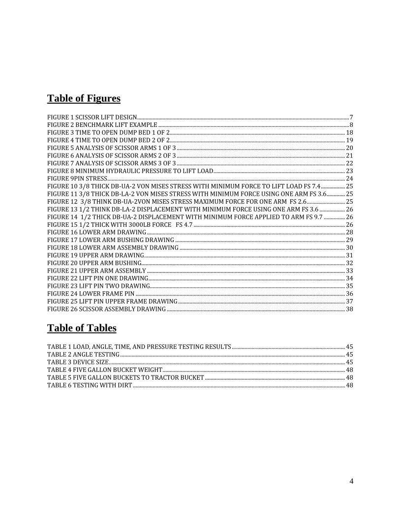
Table of Figures FIGURE 1 SCISSOR LIFT DESIGN ...................................................................................................................................................... 7 FIGURE 2 BENCHMARK LIFT EXAMPLE ....................................................................................................................................... 8 FIGURE 3 TIME TO OPEN DUMP BED 1 OF 2............................................................................................................................ 18 FIGURE 4 TIME TO OPEN DUMP BED 2 OF 2............................................................................................................................ 19 FIGURE 5 ANALYSIS OF SCISSOR ARMS 1 OF 3 ....................................................................................................................... 20 FIGURE 6 ANALYSIS OF SCISSOR ARMS 2 OF 3 ....................................................................................................................... 21 FIGURE 7 ANALYSIS OF SCISSOR ARMS 3 OF 3 ....................................................................................................................... 22 FIGURE 8 MINIMUM HYDRAULIC PRESSURE TO LIFT LOAD ............................................................................................. 23 FIGURE 9PIN STRESS ........................................................................................................................................................................ 24 FIGURE 10 3/8 THICK DB-UA-2 VON MISES STRESS WITH MINIMUM FORCE TO LIFT LOAD FS 7.4 ................. 25 FIGURE 11 3/8 THICK DB-LA-2 VON MISES STRESS WITH MINIMUM FORCE USING ONE ARM FS 3.6 ............. 25 FIGURE 12 3/8 THINK DB-UA-2VON MISES STRESS MAXIMUM FORCE FOR ONE ARM FS 2.6 ........................... 25 FIGURE 13 1/2 THINK DB-LA-2 DISPLACEMENT WITH MINIMUM FORCE USING ONE ARM FS 3.6 .................. 26 FIGURE 14 1/2 THICK DB-UA-2 DISPLACEMENT WITH MINIMUM FORCE APPLIED TO ARM FS 9.7 ............... 26 FIGURE 15 1/2 THICK WITH 3000LB FORCE FS 4.7 ........................................................................................................... 26 FIGURE 16 LOWER ARM DRAWING ............................................................................................................................................ 28 FIGURE 17 LOWER ARM BUSHING DRAWING ........................................................................................................................ 29 FIGURE 18 LOWER ARM ASSEMBLY DRAWING ..................................................................................................................... 30 FIGURE 19 UPPER ARM DRAWING .............................................................................................................................................. 31 FIGURE 20 UPPER ARM BUSHING................................................................................................................................................ 32 FIGURE 21 UPPER ARM ASSEMBLY ............................................................................................................................................ 33 FIGURE 22 LIFT PIN ONE DRAWING ........................................................................................................................................... 34 FIGURE 23 LIFT PIN TWO DRAWING.......................................................................................................................................... 35 FIGURE 24 LOWER FRAME PIN .................................................................................................................................................... 36 FIGURE 25 LIFT PIN UPPER FRAME DRAWING ...................................................................................................................... 37 FIGURE 26 SCISSOR ASSEMBLY DRAWING .............................................................................................................................. 38
Table of Tables TABLE 1 LOAD, ANGLE, TIME, AND PRESSURE TESTING RESULTS ................................................................................ 45 TABLE 2 ANGLE TESTING ............................................................................................................................................................... 45 TABLE 3 DEVICE SIZE ....................................................................................................................................................................... 45 TABLE 4 FIVE GALLON BUCKET WEIGHT ................................................................................................................................. 48 TABLE 5 FIVE GALLON BUCKETS TO TRACTOR BUCKET ................................................................................................... 48 TABLE 6 TESTING WITH DIRT ...................................................................................................................................................... 48

5
Abstract The project was motivated by a need to create a device that would cause a small truck or trailer
bed to lift up quickly and dump its contents. This would eliminate the need to use manual
physical labor, which is both slow and exhausting. Additional design constraints require the
stroke and diameter of the cylinder to be 6” x2”. A design was conceived with the intent to
incorporate a less costly device onto an existing trailer frame that would lift the bed and dump
the load. With this in mind, a scissor lift device would have two basic requirements, first to lift
500 pounds and second to achieve a 40 degree angle of lift. The intended design is called a
scissor lift. Lifting mechanisms for dump trucks are too large and expensive for use on a small
six foot trailer. Designing a lift to use a smaller cylinder to accomplish the same task as a larger
lift, was accomplished with engineering design. This smaller cylinder presents a geometric
challenge so there is enough lift to tilt and dump the load. To accomplish this, the lift will have
to accommodate the cylinder to transfer its force through the arms. The calculations predicted
that a .5 gpm hydraulic pump would take 62 seconds to lift 500 pounds, dump and lower the
load. Initial tests indicated a tilt goes to 39 degrees.

6
INTRODUCTION Motivation and Scope This project was motivated by a need to create a device that would cause a small truck or trailer
bed to lift up quickly and dump its contents, eliminating the need to use manual physical labor,
which is both slow and exhausting. This device will be incorporated into a homemade trailer and
be engineered to lift up the surface of the dump bed to an angle sufficient to empty the contents
consisting of dirt, rock, grass, wood or similar materials. The intended use for this device would
be in a farm or similar setting where a minimal labor force is available. This project is being
approached as a single individual, as his MET senior project. The majority of the effort for the
individual will be in the design and analysis of the scissor arms. This will be the most critical
part of the system. There will also be considerable effort in the machining and assembly
necessary in the construction of the device. This project will consist of three areas, design,
manufacturing and testing.
Function Statement The function of the mechanical device is to lift and tilt a dump bed that facilitate the unloading of
various materials. Atual
Design Requirements In order to fulfill the requirements of this project, the device must meet these parameters:
It must be compact. 26”x16”x12”
It must tilt a 6-foot bed to a 40º angle.
It must be able to lift a load with a cylinder with a maximum extension of 6 inches.
Must lift up to 500 pounds centered on the dump bed, located three feet from the hinge
point.
Must be able to lift the load with an input pressure of 1000 PSI or less.
Engineering Merit This problem presents several engineering challenges and opportunities for the optimization of
the device. The main engineering challenge consists of creating a design that uses a cylinder that
achieves the necessary tilt and lift to unload a dump bed, while maintaining a lower cost to
produce. Therefore the device will be optimized for cost and size using a smaller cylinder for the
lift, because commercially available lifts are expensive and larger than what’s required or needed
for this application. This project will also involve areas of shear stress, moment, and hydraulics.
Success Criteria This project will be successful if the device is able to lift a load of 500 pounds, dump the load,
and then return to the starting position.

7
DESIGN & ANALYSIS Approach A design was conceived with the intent to incorporate a less costly device onto an existing trailer
frame that causes the corresponding dump bed to lift and dump a load. With this in mind the
device has two basic requirements, to lift 500 pounds and to achieve a 40º angle of lift with a
smaller, less expensive cylinder with a stroke of 6 inches. The intended design is called scissor
lift. The scissor lift will be incorporated onto a frame and be mounted below the dump bed. The
scissor lift will have pivot points and a mounting bracket with the dump bed positioned on top of
it.
Description This scissor lift will reside on the trailer frame underneath the dump bed. There are two
mounting points for the scissor lift. The scissor lift will be attached where it meets the trailer
frame and also where it meets the dump bed. These points will be welded at the correct locations
dictated by the scissor lift. The lift will have an upper and lower arm being symmetrical on both
sides with a hydraulic cylinder applying the force to the upper arm using the lower arm to help
the pivot. This device will have four pivot points that will rotate the scissor arms and cylinder.
The placement of the scissor arm would depend on the point where the 40º tilt angle of the dump
bed would be achieved. Placement of the device is also a constraint. Placing the device close to
the pivot point won’t achieve the required lifting force, and placement furthest away from pivot
point won’t achieve the 40º angle requirement. Alignment will also be an issue, and will be
taking into account. Ways to avoid misalignment would be to use C-ring to keep the arms in
place and not move. The device will need to be lubricated, for this grease fitting will be installed
at the pivot points to decrease friction.
Figure 1 Scissor Lift Design

8
Benchmark Figure 2 shows a Venco VC520 conversion hoist for trucks and is an example of what the dump
bed that was previously discussed could look like. It is designed for a 9’ to 15’ frame with
capacities of up to 20 tons with a 5” cylinder and 20” stroke. Starting price is over $2,500. In the
example the part looks like it has welded members, four pivot points, and the ability to be placed
on to a truck or trailer frame.
Performance Prediction The performance will depend on the flow rate of the pump and size of the cylinder. My
calculated prediction with a .5 gpm pump is that it will take 62 seconds to lift 500 pound, dump
and lower the load. Reference Appendix A, Figure 3 and 4, for performance calculations.
Description of Analyses The analyses began with determining the load at the initial lifting position of 500 pounds.
Reference Appendix A, Figure 5, 6 and 7, for calculations. This is where the lift is in the closed
position and has the greatest forces required to lift the bed. After finding the geometry in the
closed position and summing the moments to find the load of 700 pound acting on the upper
scissor arm for the minimize force of 2758 pounds was necessary to open the device. Then find
the necessary pressure that is required by the cylinder exert 2758 pounds. A pressure of 864 psi
is required for a two-inch cylinder. Reference Appendix A, Figure 8, for calculations.
Analysis This section will cover approach, calculated parameters, and tolerances.
Approach: The Analysis began with the need to calculate the necessary forces
required to open the scissor lift burdened by the weight of the dump bed and
its contents. Calculating the sum of the moments will accomplish this. After
this force was determined, then the forces that are on the upper arm could be
Figure 2 Benchmark Lift Example

9
evaluated. In this particular project the majority of the analysis focuses on the
upper scissor arm, this arm is the most critical and will determine if the load
can be lifted.
Optimization: This device has been optimized to use a cylinder that has a bore
size of 2 inches and stroke of 6 inches. Appendix A, Figure 5, shows the force
necessary to open the dump bed with the determined geometry. Large
cylinders that are commonly comprised of at least a 5 inch bore and a 20 inch
stroke are expensive and must be placed into a stronger, larger more costly
structure, as in Figure 2. This device is a smaller version that is similar to the
previously discussed benchmark. By using a less expensive smaller cylinder,
this new device will perform a similar function, in less space and be able to
handle smaller loads, making it more manageable and safer.
Significant cost savings will be realized by using a small cylinder. The small
cylinder can be obtained for around $70, while the cost of the large cylinder is
over $400. Costs were obtained using information from SurplusCenter.com
Required Parameters: A minimum force of 2758 pounds is required to lift the
load of 700 pounds at 31 inches. Reference Appendix A, Figure 5-7. The 700
pound load consists of 500 lbs. of material, 100 lbs. of the dump frame, and an
added 100 lbs. by the moment. 2758 pounds was found by calculating the
forces in each arm.
Calculated Parameters: In Appendix A, Figure 3, shows the estimated time it
will take the lift to dump the load with a pump flow of two GPM. It accounts
for 45 seconds for the load to be dumped out, and a total time of 49.29
seconds to lift, to dump, and to close. Figure 4 is the same calculation with a
pump that has a decreased flow rate of .5 GPM. This should slow the process
of lifting and closing and make the lift safer. Figure 8 shows the minimum
pressure required to obtain the force of 2758 pounds is 879 psi. Figure 9 is
showing the max load for the pin at 2758 pounds. Figure 10-15 is FEA done
in SolidWorks showing the von Mises stress, displacement, and what the
safety factor is for a load ranging from 2000 lbs. to 4000 lbs. on the upper
lifting arm.
Tolerances: The tolerances for this project will be different for the application.
For tolerance on the cut of plate and hole location can be looser, +/- 0.1 hole
location. The looser tolerance will help with time and machining cost. For the
holes size tolerance will be -0.0 + .05. hole size needs to be more precise for
an accurate fit for the pins. Pins need to be the most accurate with a tolerance
of +/- .01 inch.

10
Technical Risk Analysis This device has a calculated failure mode where the device will not open when it’s overloaded.
The maximum pressure for the system is 2,000 psi and lift arm will hold the maximum hydraulic
cylinder force of 6,280 pounds. When the lift is overloaded, the device will be unable to lift the
load. A safety factor of 3 is required when a force of 3000 lbs. is applied to upper arm.
METHODS & CONSTRUCTION Description When the scissor lift is being constructed certain precautions will need to take place to maintain
a precise part. The use of calipers, angle plate and other tools will help maintain the precision of
the parts during measuring and assembly.
The use of the CWU machine shop, plasma table, and other resources will be used in this project
to complete the project on time and on budget. Assembly of the scissor lift to the trailer frame
and the dump bed will happen on location.
Drawing tree The drawing tree is located in Appendix B. Looking at the Drawing tree shows the steps of
operation for the construction process of the dump bed. Following this tree will ensure the right
steps and operation occur at the proper time so nothing is started before it needs to. To finish the
scissor assembly, the DB-UA-2 and DB-LA-2 will be pinned together at their location and the
cylinder will be pinned at one end to DB-LA-2 and pinned at the opposite end to the DB-UA-2 at
their location. Look at Appendix C for device drawings and assemblies. This scissor assembly
will be pinned to the DB-LF and the DB-UF.
Parts List and Labels The parts list is located in Appendix D. The parts list indicates part number, which can also be
referenced by drawing number and a description of what the part is. The parts list also
summarizes the number of parts needed for each assembly.
Manufacturing Issues No manufacturing issues were anticipated, however a few unforeseen issues did arise and they
were solved and rectified. Three issues that arise were when using the plasma table, welding
members together and having aliment issues. When cutting the .4 inch thick steel with the
plasma table the breaker would trip after a six inches of cutting because it would over heat the
unit. To not trip the breaker when cutting, the cut was stopped ever four inches to let the unit
cool down for a minute and then started again to cut another four inches. When welding bushing
onto the lower arm there was heat distortion. This caused the ends of the arms to rise up and the
holes were not parallel to one another. To fix this issue the 5-ton pneumatic press was used to
restrain the ends. The aliment issues was also fixed when lower arms were straighten out.
11
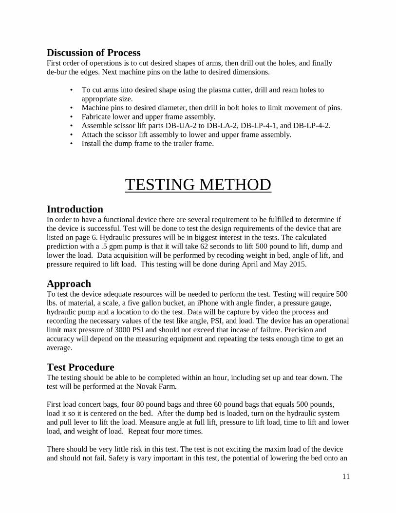
Discussion of Process First order of operations is to cut desired shapes of arms, then drill out the holes, and finally
de-bur the edges. Next machine pins on the lathe to desired dimensions.
• To cut arms into desired shape using the plasma cutter, drill and ream holes to
appropriate size.
• Machine pins to desired diameter, then drill in bolt holes to limit movement of pins.
• Fabricate lower and upper frame assembly.
• Assemble scissor lift parts DB-UA-2 to DB-LA-2, DB-LP-4-1, and DB-LP-4-2.
• Attach the scissor lift assembly to lower and upper frame assembly.
• Install the dump frame to the trailer frame.
TESTING METHOD
Introduction In order to have a functional device there are several requirement to be fulfilled to determine if
the device is successful. Test will be done to test the design requirements of the device that are
listed on page 6. Hydraulic pressures will be in biggest interest in the tests. The calculated
prediction with a .5 gpm pump is that it will take 62 seconds to lift 500 pound to lift, dump and
lower the load. Data acquisition will be performed by recoding weight in bed, angle of lift, and
pressure required to lift load. This testing will be done during April and May 2015.
Approach To test the device adequate resources will be needed to perform the test. Testing will require 500
lbs. of material, a scale, a five gallon bucket, an iPhone with angle finder, a pressure gauge,
hydraulic pump and a location to do the test. Data will be capture by video the process and
recording the necessary values of the test like angle, PSI, and load. The device has an operational
limit max pressure of 3000 PSI and should not exceed that incase of failure. Precision and
accuracy will depend on the measuring equipment and repeating the tests enough time to get an
average.
Test Procedure The testing should be able to be completed within an hour, including set up and tear down. The
test will be performed at the Novak Farm.
First load concert bags, four 80 pound bags and three 60 pound bags that equals 500 pounds,
load it so it is centered on the bed. After the dump bed is loaded, turn on the hydraulic system
and pull lever to lift the load. Measure angle at full lift, pressure to lift load, time to lift and lower
load, and weight of load. Repeat four more times.
There should be very little risk in this test. The test is not exciting the maxim load of the device
and should not fail. Safety is vary important in this test, the potential of lowering the bed onto an

12
extremity could be possible. To keep everyone safe during the test communication needs to be
present, before the lift is lifted operator needs to call out “lifting” and hear the ok to lift. The
same thing needs to be present when lowering the lowed, operator calls out “lowering” and waits
for the ok before lowering. A clear path around the trailer needs to be present to not cause any
tripping hazards. The test will be considered successful if the load can be lifted and lowered.
Deliverables There are five parameter that this test will be testing. They are size of the device, angle of tilt,
achieve angle with six inch stroke cylinder, lift 500 pounds centered on dump bed, and lift with
an input pressure of 1000 PSI. The test will be successful if the device can get to a 40 degree
angle, use a stoke of 6 inches, lift 500 pound load under 1000 PSI. Reference Appendix H for
results.
After testing the device it was able to lift 500 pounds centered on the bed with an input pressure
of 1200 PSI. The calculated lifting pressure of 1000 PSI came from a bed weight of 100 pounds.
With 200 more PSI required to lift the load then what was calculated was due to a under estimate
of the bed weight which is closer to 250 to 300 pounds. The pressure to lift the bed with no load
was 700 PSI. The angle achieve was 39 degrees and has a number of factors why it did not
achieve 40 degrees, one was is that the mounting points of the device could be off by one inch
and would have changed the angle by a degree. 39 degrees will be sufficient to dump a load and
will not decrees the efficiency of the device.
Over all the testing was a success. The 1200 PSI to lift the load and bed was due to a under
estimate of the bed weight, it only took 500 PSI to lift the load. With the angle being 39 degrees
witch also pass the test and will be consisted successful.
BUDGET/SCHEDULE/PROJECT
MANAGEMENT
Proposed Budget The proposed budget will include all the material needed for the project. A parts list is shown in
Appendix D. A budget is shown in Appendix E. Materials will be purchased from local
hardware stores, McMaster-Carr and Surplus Center.
Labor: 224.5 hours of labor are estimated to complete this project. Labor will be
performed by Mr. Zachary Pate, valuing his time at $17 per hour. No labor
outsourcing will be needed because Zachary Pate has the necessary skills to
produce this device. Help with installing the lift may be needed.

13
After completing the project total time spent was 230.8 hours. An underestimation
of extra hours come from time spent writing the proposal and constructing a
frame for the lift.
Estimated Total Cost: The estimated budget for this project is $763.44 The budget
took into account the overall cost to purchase materials. Anticipated cost with
donated materials is $98.73 Reference Appendix E for individual part cost. Total
cost spent out of pocket was $110.35. This was $11.62 over budget, making the
overall cost $775.06 to construct a new lift.
Funding Sources: The funding for this project will come out of pocket, with some
resources donated by the Novak Farm.
Proposed Schedule The schedule will lay out a reasonable time frame in which the project will be completed. It will
cover the proposal, manufacturing, and testing of the device. The schedule for this project is
shown in Appendix F, shown as a Gantt chart. This project will be completed by the last week of
spring quarter.
Project Management This design is susceptible to three major risks including cost, time, and manufacturability. The
risk associated with costs is defined by staying within the specified budget and will depend on
finding the materials at prices that were researched for this purpose. Time constraints for the
project also produce a risk because the project will need to be designed, manufactured, and tested
within a 30 week time period. The last risk factor is manufacturability; it will need to be
fabricated to the anticipated design parameters.
Safety is an important part of this project. Injury will be prevented by consistent use of personal
protection equipment as needed. The use of hydraulics with high pressure lifting heave loads
creates opportunity for injury. Common sense will be needed when building and operating the
device.
I. Human Resources: The lead investigator is responsible for the engineering,
machining, and construction. The individual is also responsible for finding
additional resources when needed.
II. Physical Resources: Central Washington University has a full machine shop as
well as other labs that are available to students. The Novak Farm will be used as a
location for assembly.
III. Soft Resources: This project heavily depended on the use of software. Software
being used is Solid Works, Microsoft Office, MasterCam, and CNC software.

14
IV. Financial Resources: A financial resource for this project is, Novak Farm. They
will donate some material for the project. The lead investigator will provide
funding for the rest of the project.
DISCUSSION
Design Evolution The project started out as an idea sketched on paper. After having difficulty finding the workable
geometry by hand, it was modeled with two 1”x.5”x20” linking arms in SolidWorks, helping
find the necessary dimensions. By trial and error, the location of the pivot points was identified
to find the correct placement to achieve a 40º angle with six inches of stroke. After some analysis
was done on the two linking arms, and found that the input force to lift the dump bed was over
4000 pounds and pointed too much in the x-axis making it unable to lift the designated load of
500 pounds. Then a redesign of the upper linking arm connected to the cylinder was designed to
be more practical by changing the input angle of the cylinder to 9.7 degrees and lowed the input
force to 2758 pounds. See Figure 5, Appendix A. This designed changed improved the device by
lowering the necessary input force and making capable of lifting a larger load. Next, after
learning that the plasma table could not cut 1/2 inch thick steel, the linking arm was analyzed
using 3/8 inch thick steel and determined it would not yield using a thinner steel, see Appendix
A, Figure 10 and 14.
Project Risk Analysis Working with high pressure and heavy loads involves a significant safety risk. The highest risk
could be identified as a failure of the scissor arms and if precautions are not followed, could lead
to bodily injury. Event of injury is low, but could accrue if the system is overloaded or someone
places an extremity into the lift as it is expanding. With this in mind, the arms have been
engineered as the strongest component, purposefully designing the cylinder to be the weakest
link, thus reducing the event of scissor arm failure.
Successful After testing is completed the device and design will be considered successful or not. Success
will also depend on if the device is functional and can be completed in time and on budget.
After constructing, and testing the device it was considered a successful. It was able to lift the
500 pounds and tilted to a adequate angle to dump the load.
Next Phase The next phase is to use the product at the Novak Farm for daily use. After observing the device
in action a redesign could be made to improve the device.

15
CONCLUSION
The Dump Bed Lifting Mechanism has conceived and analyzed as a device that meets the
function requirements asked for. The necessary parts have been listed and a description of how
they will be created has been presented. By staying within a specified reasonable budget,
incorporating commonly found materials into its design, an efficient, compact functional device,
it is ready to be manufactured.
Analysis had been performed that will substantiate the feasibility and probable success of this
project. Calculations have been made to show that minimum expectations will be met for the
success of the project. The device has been thoroughly contemplated and analyzed in its design,
usefulness and functionality, thus proving by its design parameters an efficient, less costly
solution to a device that can be commonly used in an everyday farm setting.
This project meets all the requirements for a successful senior project, including having:
• Substantive engineering merit by producing efficient lifting capabilities with a
compact size.
• Compact size benefits include lower costs predicted by the projected budget.
• Principle investigator will have produced a device that substantially eliminates most
of the physical labor required to move material and significantly lessens the time
required to do so.

16
ACKNOWLEDGEMENTS
Thanks are due to Dr. Craig Johnson, Mr. Roger Beardsley, and Mr. Charles Pringle for their
mentoring and advice. Central Washington University for the use of their machine shop and
facilities, tools, software, references and resources required for the completion of this project.
Much appreciation is also due to Mr. Geoffrey Pate, an outside entity for his mentoring of the
principal engineer and to the Novak Farm for donated resources.

17
Reference
Hibbeler, R.C. (2014). Statics & Mechanics of Materials. Boston: Pearson.
Benchmark. http://www.kgequipment.com/steel-2/hoist/

18
APPENDIX A - ANALYSES
Figure 3 Time to Open Dump Bed 1 of 2

19
Figure 4 Time to Open Dump Bed 2 of 2

20
Figure 5 Analysis of Scissor Arms 1 of 3

21
Figure 6 Analysis of Scissor Arms 2 of 3

22
Figure 7 Analysis of Scissor Arms 3 of 3

23
Figure 8 Minimum Hydraulic Pressure to Lift Load

24
Figure 9Pin Stress

25
Figure 10 3/8 Thick DB-UA-2 von Mises Stress With Minimum Force to Lift Load FS 7.4
Figure 11 3/8 Thick DB-LA-2 Von Mises Stress With Minimum Force Using One Arm FS 3.6
Figure 12 3/8 Think DB-UA-2Von Mises Stress Maximum Force For One Arm FS 2.6

26
Figure 14 1/2 Thick DB-UA-2 Displacement With Minimum Force Applied to Arm FS 9.7
Figure 13 1/2 Think DB-LA-2 Displacement with Minimum Force Using One Arm FS 3.6
Figure 15 1/2 Thick with 3000lb Force FS 4.7

27
APPENDIX B – DRAWING TREE
Completed Dump Bed Assembly
Hydraulic System
Cylinder
Hoses 72"
Spool Valve
Hose 24"
Pump
Purchase Hydraulic
System Material
Frame and ScissorAssembly
Sicssor
Assembly
Pin Assembly Together
DB-UA-2
Machine
DB-UA-2
Purchase Material For
DB-UA-2
Weld Parts Together
Machine
DB-HI-6
Purchase Materila For DB-FP-6
DB-LA-2
Machine
DB-LA-2
Purchase Material For
DB-LA-2
DB-LP-4
Machine
DB-LP-4
Purchase Material
For DB-LP-4
Cylinder
Frame
Assembly
DB-UF-2
Weld Parts Together
Machine
DB-UF-2 Parts
Purchase Material For
DB-UF-2
DB-LF-2
Weld Parts Together
Machine DB-LF-2 Parts
Purchase Material For
DB-LF-2
28
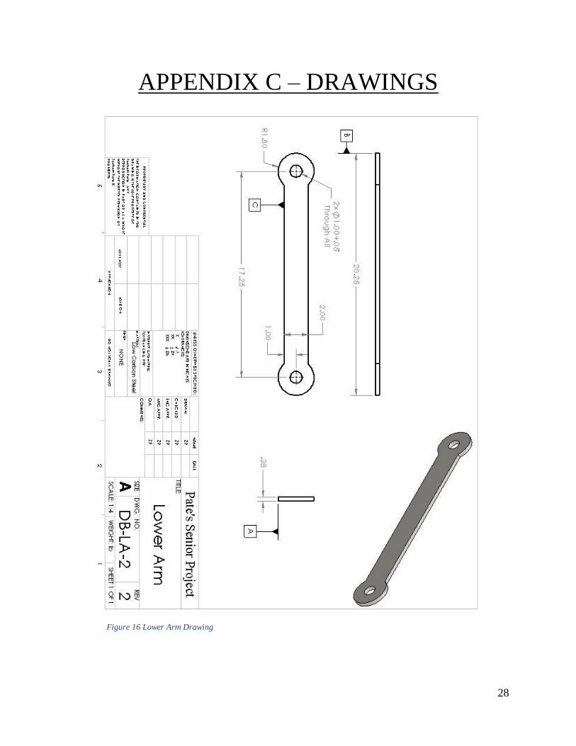
APPENDIX C – DRAWINGS
Figure 16 Lower Arm Drawing

29
Figure 17 Lower Arm Bushing Drawing
30
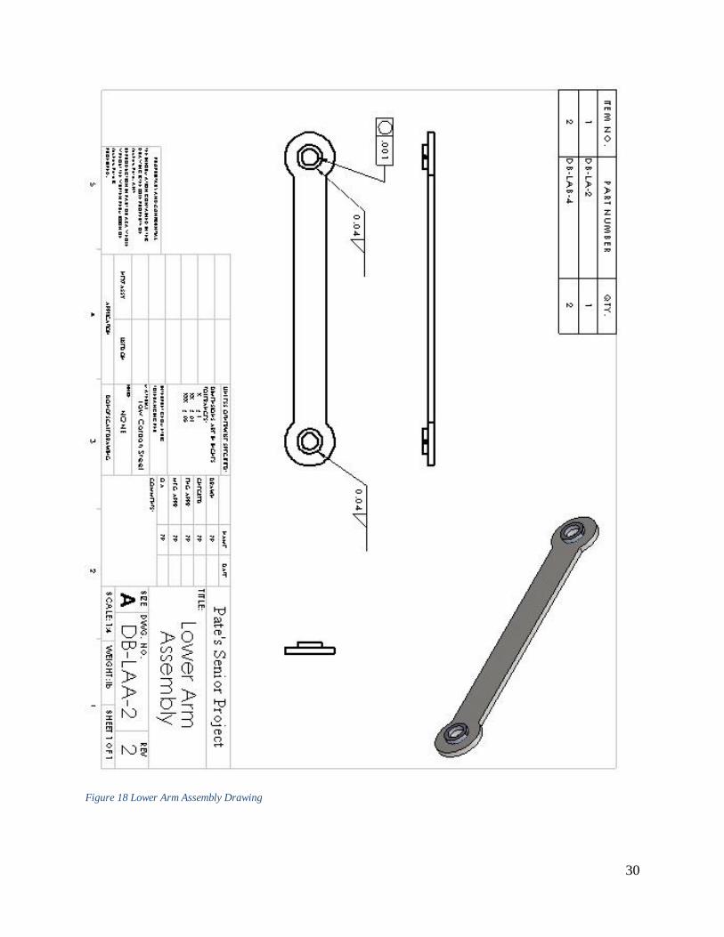
Figure 18 Lower Arm Assembly Drawing
31
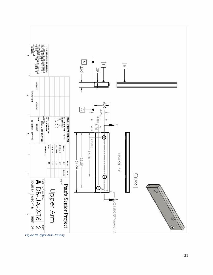
Figure 19 Upper Arm Drawing
32
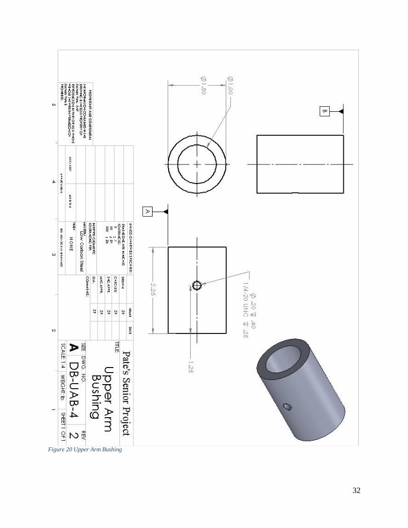
Figure 20 Upper Arm Bushing

33
Figure 21 Upper Arm Assembly

34
Figure 22 Lift Pin One Drawing

35
Figure 23 Lift Pin Two Drawing

36
Figure 24 Lower Frame Pin

37
Figure 25 Lift Pin Upper Frame Drawing

38
Figure 26 Scissor Assembly Drawing

39
APPENDIX D – PARTS LIST
Item Part # Description Quantity
1 DB-LA-2 Lift's Lower Arm 2
2 DB-UA-2 Lift's Upper Arm 2
3 DB-LP-4-1 Lift Pin UA/LA 1"dim by 9" long 1
4 DB-LP-4-2 Lift Pin UA/Cly 1"dim by 9" long 1
DB-LAB-4 Lower Arm Bushings 4
5 DB-UAB-6 Upper Arm Bushings 6
6 HP-1 Hydraulic Pump 1
7 HC-1 Hydraulic Cylinder 1
8 HH-P-2 Hydraulic Hose 24" 2
9 HH-C-2 Hydraulic Hose 72" 2
10 HSV-1 1 Spool Hydraulic Valve 1
11 DB-LF-1 Lower Trailer Frame 1
12 DB-UF-1 Upper Trailer Frame 1
13 DB-SR-8 C-Style Snap Rings 12
14 LP-W-25 Washer ID 5/8 in 8
15 LP-N-25 Bolt 5/8x3/4in 20 TPI 8
16 LP-B-4 E-Style External Retaining Rings 1 Packages of 100
17 FG-6 Grease Fittings Assortment 1 Package of 110
18 DB-LFP-1 Lower Frame Pin 1"dim by 15" long 1
19 DB-UFP-1 Upper Frame Pin 1"dim by 9" long 1
Zachary Pate
Project Name: Dump Bed Lifting Mechanism
Senior Project Part List

40
APPENDIX E - BUDGET
Item Part # Description Source ID # Price Quantity Subtotal Actual cost Acquisition
1 DB-UA-T6-2 Raw Steel Tubes 2"x6"x36" Online Metals 2x5x.25x60 $111.53 1 $121.57 $0.00 Donated
2 DB-LA-2 Raw Steel Plate, 5"x12"x.375" Novak Farm PS5X.375 $50.20 1 $54.72 $0.00 Donated
3 DB-LP-4 Pin material 1"x6' steel Rod Western Metal 8920k231 $27.50 1 $29.98 $29.98 Purchased
4 DB-U-L-AB-10 DOM Tube 1.5"x.25x1"x6' Online Metals DOM1.5-25 $34.94 1 $43.73 $43.73 Purchased
5 LP-B-4 E-Style External Retaining Rings Amazon B000NB9G2Y $5.95 1 $6.49 $6.49 Purchased
6 SR-8 C-Style Snap Rings Hardware store SR-8 $0.80 12 $9.67 $9.67 Purchased
7 LP-N-8 Bolt 5/8x3/4in 20 TPI Fred Meyers H02232392 $1.49 2 $3.11 $3.11 Purchased
8 LP-W-8 Washer ID 5/8 in Fred Meyers W02232 $1.49 2 $3.11 $3.11 Purchased
9 FG-6 Grease Fittings Assortment Amazon 10035 SAE $13.08 1 $14.26 $14.26 Purchased
10 HP-1 Hydraulic Pump 12 VDC Surpluc Center 97384 $249.95 1 $272.45 $0.00 Donated
11 HC-1 Hydraulic Cylinder 2x6x1.125 Surpluc Center 9-8534-6 $58.95 1 $64.26 $0.00 Donated
12 HH-P-2 Hydraulic Hose 3/4"x24" NPTM Surplus Center 9-078-24 $15.95 2 $33.34 $0.00 Donated
13 HH-C-2 Hydraulic Hose 1/2"x60" NPTM Surplus Center 905-1260 $14.95 2 $31.25 $0.00 Donated
14 HSV-1 1 Spool Hydraulic Valve Surplus Center 9-1262 $79.95 1 $87.15 $0.00 Donated
15 DB-MACH Machining Cost CWU Time $0.00 40 $0.00 $0.00 Work
$775.06 $110.35
Zachary Pate
Project Name:
Senior Project Buget
Dump Bed Lifting Mechanism

41
APPENDIX F - SCHEDULE
Duration
TASK: Description Est. Actual November Dec January February March April May June
11
/03
/14
11
/10
/14
11
/14
/14
11
/24
/14
12
/01
/14
12
/10
/14
01
/05
/15
01
/12
/15
01
/19
/15
01
/26
/15
02
/02
/15
02
/09
/15
02
/16
/15
02
/23
/15
03
/02
/15
03
/09
/15
03
/16
/15
03
/23
/15
03
/30
/15
04
/06
/15
04
/13
/15
04
/20
/15
04
/27
/15
05
/04
/15
05
/11
/15
05
/18
/15
05
/25
/15
06
/01
/15
ID (hrs) (hrs)
1 Proposal*
1a Outline 3.0 3.1
1b Intro 2.0 4.0
1c Methods 3.0 3.0
1d Analysis 6.0 7.0
1e Discussion 2.0 2.5
1f Parts and Budget 3.0 3.2
1g Drawings 5.0 7.0
1h Schedule 1.0 3.4
1i Summary & Appx 1.0 1.2
subtotal: 26.0 34.4
2 Analyses
2a Hydraulic OpenTime 1.0 1.0
2b Force at Lift Point 2.0 1.0
2c Statics 12.0 13.0
2d Force of Cyliner 1.0 1.0
2e Pin shear 2.0 3.0
2f FEA 5.0 4.5
subtotal: 23.0 23.5
3 Documentation
3a Part 1 Lower Arm LA-1,2 2.0 2.0
3b Part 2 Upper arm LU-1,2 3.0 2.0
3c Part 3 Pin LP-1,2 UP-1,2 2.0 2.0
3d Subassemly Sissor Lift 1.0 2.0
3i Assemly 1.0 1.0
3j Drawing 3.0 5.0
3l ANSIY14.5 Compl 2.0 2.0
subtotal: 14.0 16.0
Principal Investigator: Zachary Pate
PROJECT TITLE: Dump Bed Lifting Mechanism

42
4 Proposal Mods
4a Project DB Schedule 1.0 4.0
4b Project DB Part Inv. 1.0 1.0
4c Crit Des Review* 1.0 2.0
subtotal: 3.0 7.0
7 Part Construction
7a Order Parts 4.0 3.0
7b Part 1 LA-1 2.5 2.0
7c Part 2 LA-2 2.5 2.0
7d Part 3 Upper arm UA-1 6.0 4.0
7e Part 4 Upper arm UA-2 5.0 3.5
7f Part 5 LP-1 4.0 4.1
7g Part 6 LP-2 3.0 2.3
7h Part 8 UAB-6-1 2.0 1.7
7i Part 9 UAB-6-2 1.5 0.7
7j Part 10 UAB-6-3 1.5 0.7
7k Part 11 UAB-6-4 1.5 0.7
7l Part 12 UAB-6-5 1.5 0.7
7m Part 13 UAB-6-6 1.5 0.7
7n Part 14 LAB-4-2 1.0 1.2
7o Part 15 LAB-4-4 1.0 1.0
7q Part 16 DB-LF-1 10.0 8.0
7r Part 17 DB-UF-2 7.0 1.8
7s Part 18 DB-LFP-1 0.5 0.5
7t Part 19 DB-UFP-1 0.5 0.5
7u Take Part Pictures 1.5 0.2
7v Update Website 1.0 0.2
7x Manufacture Plan* 2.0 0.4
subtotal: 57.0 39.9
69.4
9 Device Assembly
9a Assemble UA, UAB 4 6.5
9b Assemble LA, LAB 2 5
9c Assemble LP, LP, LA, UA 3.5 4.5
9d Assemble cylinder to lift 2.0 0.5
9e Frame Assembly 12 20
9f Installing lift 1 4
9g Take Dev Pictures 1.0 0.5
9h Update Website 2.0 0.0
subtotal: 21.5 29.5

43
10 Device Evaluation
10a List Parameters 5.0 2.0
10b Design Test&Scope 4.0 2.0
10c Obtain resources 3.0 3.0
10d Make test sheets 3.0 1.0
10e Plan analyses 5.0 2.0
10g Test Plan* 5.0 4.0
10h Perform Evaluation 3.0 4.0
10i Take Testing Pics 2.0 1.5
10h Update Website 2.0 1.0
subtotal: 32.0 20.5
11 495 Deliverables
11a Get Report Guide 3.0 3.0
11b Make Rep Outline 3.0 3.0
11c Write Report 27.0 40.0
11d Make Slide Outline 3.0 3.0
11e Create Presentation 3.0 3.0
11f Make CD Deliv. List 2.0 2.0
11e Write 495 CD parts 2.0 2.0
11f Update Website 3.0 2.0
11g Project CD* 2.0 2.0
subtotal: 48.0 60.0
Total Est. Hours= 224.5 230.8 =Total Actual Hrs
Labor$ 17 $3,817 $3,923
Note: Deliverables*
Draft Proposal
Analyses Mod
Document Mods
Final Proposal
Part Construction
Device Construct
Device Evaluation
495 Deliverables

44
APPENDIX G – EXPERTISE AND
RESOURCES
Resources used were the CWU machine shop, and Novak Farm for assembly and testing.
Expertise was given by Mr. Geoffrey Pate, mentor of the principal engineer.

45
APPENDIX H – EVALUATION SHEET
The following table displays the operation design requirement and will be recorded when the
device is tested.
Design Requirement Load Test and Prediction Test.
Table 1 Load, Angle, Time, and Pressure Testing Results
Angle Test
Trial Angle
1 39
2 39
3 39
Table 2 Angle Testing
The following table displays size design requirement.
Size of the Device Measured (Inches) Required (Inches)
Length 24 26
Width 9 12
Height 14 16 Table 3 Device Size
Trial Load Angle Time PSI
Prediction 500 lb 40 degs 62 sec 1000
1 0 39 20 700
2 500 39 22 1200
3 500 39 19 1200
4 500 39 20 1200
5 500 39 21 1200
46
APPENDIX I – TESTING REPORT
Objective: To collect data and analyze the performance of a dump bed lifting device to determine
weight lifted, lifting time, and pressure required to lift load.
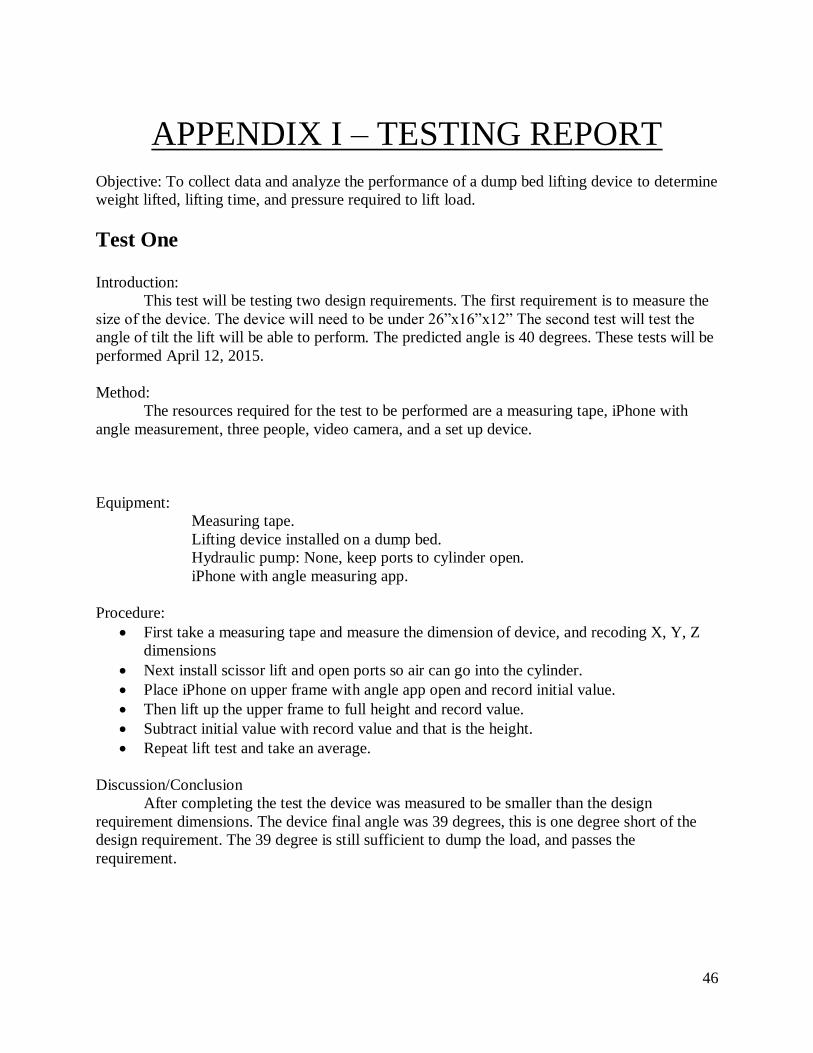
Test One Introduction:
This test will be testing two design requirements. The first requirement is to measure the
size of the device. The device will need to be under 26”x16”x12” The second test will test the
angle of tilt the lift will be able to perform. The predicted angle is 40 degrees. These tests will be
performed April 12, 2015.
Method:
The resources required for the test to be performed are a measuring tape, iPhone with
angle measurement, three people, video camera, and a set up device.
Equipment:
Measuring tape.
Lifting device installed on a dump bed.
Hydraulic pump: None, keep ports to cylinder open.
iPhone with angle measuring app.
Procedure:
First take a measuring tape and measure the dimension of device, and recoding X, Y, Z
dimensions
Next install scissor lift and open ports so air can go into the cylinder.
Place iPhone on upper frame with angle app open and record initial value.
Then lift up the upper frame to full height and record value.
Subtract initial value with record value and that is the height.
Repeat lift test and take an average.
Discussion/Conclusion
After completing the test the device was measured to be smaller than the design
requirement dimensions. The device final angle was 39 degrees, this is one degree short of the
design requirement. The 39 degree is still sufficient to dump the load, and passes the
requirement.

47
Test Two
Introduction:
This test will be testing two design requirements. The first requirement is to measure the
time the device takes to open. The predicted opening, dumping, and closing time is 62 seconds.
The second test will perform a load test of 500 pounds. The predicted pressure to open the lift is
1000 PSI. These tests will be performed April 26, 2015.
Method:
The resources required for the test to be performed are a hydraulic system with pressure
gage, iPhone with angle measurement app, three people, video camera, 500 pounds of concert,
and working dump bed trailer.
Equipment:
500 pound of concrete, three 60 pound bags, and four 80 pound bags.
Lifting device installed on a dump bed trailer.
Hydraulic system: Connected to scissor lift.
iPhone with angle measuring app.
Procedures:
Set up hydraulic system.
Open lift and record pressure to open the bed.
Then load concrete into bed and center it three feet back from the hinges so load is 500
pounds centered.
Repeat procedure four more times.
Discussion/Conclusion
After testing the load requirement of 500 pounds the device was able to lift the load. The
only issue was it took 1200 PSI to lift the load. This was due to a under calculation of the weight
of the bed where 100 pounds was estimated where the bed weighted closer to 300 pounds witch
required a extra 200 PSI to lift the bed.

48
APPENDIX J – TESTING DATA
Weight of Dirt Table
Volume of Five Gallon Bucket to Tractor Bucket
Testing of the device.
Number Bucket
Weight of Bucket
1 48
2 46
3 48
4 50
5 50
6 50
7 50
8 0
Total 342
Table 4 Five Gallon Bucket Weight
1 2 Average
Weight of Five Gallon
Bucket
50 pounds 50 pounds 50 pounds
Number of Buckets in
Tractor Bucket
7 8 8
Table 5 Five Gallon Buckets to Tractor Bucket
Weight of Tractor
Bucket
Number of Tractor
Buckets Loaded
Weight in Dump Bed Was Dump
Successful
350 Lbs, 400 Lbs 2 750 Pounds Yes
400 Lbs,400 Lbs 2 800 pounds Yes
Table 6 Testing with Dirt

49
APPENDIX K - RESUME
ZACHARY PATE [email protected]
253.310.6186
EDUCATION
CENTRAL WASHINGTON UNIVERSITY January
2011 - June 2015
Ellensburg, Washington
BACHELOR OF SCIENCE; MECHANICAL ENGINEERING TECHNOLOGY
EXPERIENCE EPIC AIRCRAFT June 2014 –
September 2014 Bend, Oregon
Materials and Process Engineer Intern
Worked with a six member team of interns to establish a materials testing lab focusing
on carbon fiber, fiberglass, and adhesives bonding for the certification of the E1000
airplane
Worked with various instruments such as MTS, DMA, DSC, drill press, surface
grinder, slow-speed-saw, vertical mill, and lathe to prepare and test specimens flowing
ASTM standers
Responsibilities included specimen preparation, dimensioning, material testing (SBS,
CDP, DCB, Compression, Lap Shear, and Tensile Testing) data reduction,
implementing new test plans, writing technical documents, laying up panels, specimen
fixture development, machining, and welding
Demonstrated the ability to learn quickly all aspects of testing process and to
effectively execute them
Individual projects included redesign of lap shear press, implementing hardness tester
and DCB fixture and test plan into the testing process
Designed and made drawings of fixtures to be sent out and built
Specialized work with layup, surface prep, secondary bonding, composite bonding
fracture analysis, determining failure modes, and parameters for acceptable or
unacceptable failure modes (adhesive/cohesive/interlaminer)
DANICI ELECTRIC July 2007 –
September 2013
Breckenridge, Colorado

50
Apprentice Electrician
Lead apprentice on both residential and commercial electrical projects to execute
wiring, install breaker boxes and light fixtures
Executed all phases of electrical project from rough to finishing work
Demonstrated ability to learn quickly and effectively under journeymen and master
electricians.
Supervised and trained four new apprentices to further scale quality work
UNITED YOUTH CAMPS July
2012, July 2013
Tillamook, Oregon
Waterski Instructor
Assisted teaching 100+ youth ages 11-19 how to water ski and wake board
Lead safety monitoring for all youth and staff at waterskiing location with zero injuries
Communicating effectively with staff and campers.
Experience explaining waterskiing and wakeboarding techniques to campers while
keeping them motivated.
THE DISPATCH September
2007 – June 2009
Eatonville, Washington
Sports Writer
Self-managed writing of weekly articles covering community sporting affairs,
including tennis and track
Published articles under strict deadlines
Electronic submission and peer editing
SKILLS COMPUTER PROGRAMS
SolidWorks -Certified Associate, Mastercam, Microsoft Word, Excel, PowerPoint, and
AutoCAD, MSC-Pantran
DRAFTING
For senior project I used SolidWorks to design 3D parts and assemblies, then export them
to a 2D drawing so parts could be build according to drawing
Experience with drawing to ANSY Y14 Standards
Have had GD&T tolerance and drafting experience
MACHINING
Vertical mill, lathe, 3 axis CNC mil, drill press, plasma table
BUSINESS
Management, public speaking, reports
51
PROFESSIONAL SOCIETY
AMERICAN SOCIETY OF MECHANICAL ENGINEERS, January
2011 – Present
Ellensburg, Washington
Officer, Vice President (2014-2015)
Collaborated with other club officers to plan agenda and activities for club meetings
2014 Student Professional Development Conference (SPDC) poster competition
competitor describing Is Hydropower Worth It?
Club Treasurer from 2011-2014, managed, monitored and communicated club finances
and spending
Executed planning and financing of the 2012 Student Professional Development
Conference at CWU
SOCIETY OF MANUFACTURING ENGINEERS January
2014 – Present
Ellensburg, Washington
Member, CWU Chapter Member (2014-2015)
Participating in weekly club meetings
Attends club facilities tour to SGL Composite, AGC Composites, Genie, GE Aviation,
Pearson Packaging, Wagstaff, MacDonald-Miller
Attended district conference on how SME can sever members
REFERENCES Brock Strunk, Chief Structures Engineer 541.531.9552
Dave Goethals, High School Teacher 253.862.5565
David Novak, Danici Electric Owner 970.390.1173
Keith Tomes, Superintendent 559.631.5871
Mike Shide, Electrical Engineer 626.840.0450
Rex Sexton, UCG Camp Director 360.798.2921