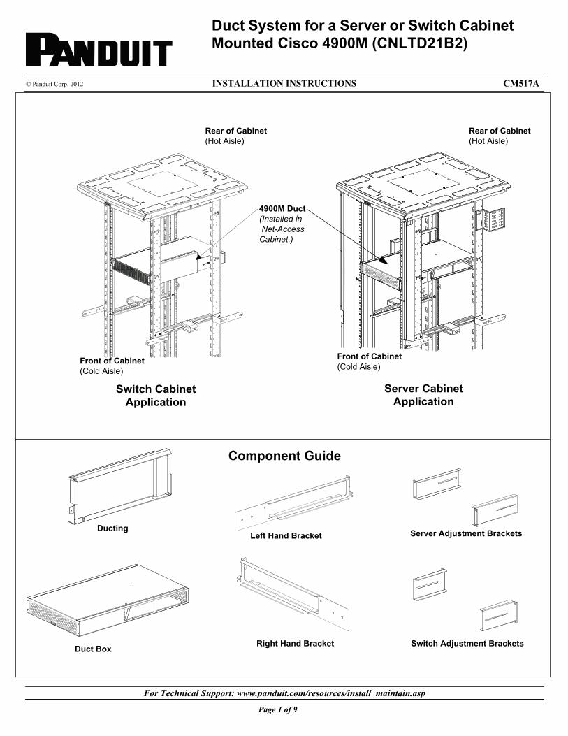
duct system for a server or switch cabinet mounted cisco...
TRANSCRIPT
For Technical Support: www.panduit.com/resources/install_maintain.asp
INSTALLATION INSTRUCTIONS © Panduit Corp. 2012 CM517A
4900M Duct (Installed in Net-Access Cabinet.)
Duct Box Right Hand Bracket
Left Hand Bracket
Duct System for a Server or Switch Cabinet Mounted Cisco 4900M (CNLTD21B2)
Component Guide
Front of Cabinet(Cold Aisle)
Rear of Cabinet(Hot Aisle)
Server Adjustment BracketsDucting
Switch Adjustment Brackets
Front of Cabinet(Cold Aisle)
Rear of Cabinet(Hot Aisle)
Switch Cabinet Application
Server Cabinet Application
Page 1 of 9

For Technical Support: www.panduit.com/resources/install_maintain.asp
INSTALLATION INSTRUCTIONS © Panduit Corp. 2012 CM517A
Table�of�Contents���4900M�Ducting�
Section�1��SERVER�APPLICATION PageDetermine�Location�of�4900M�Duct……………………………………………...………………..……………………………………1Cage�Nut�Installation…………………………………………………………………………………………………………………………… 2Left�and�Right�Hand�Bracket�Installation……………………………………………...………………..………………………………3Ducting�Installation………………………………………………………………………………………………………………………………4Duct�Box�Installation…………………………..…………………………………………………………………………………………………5
Section�2��SWITCH�APPLICATION PageDetermine�Location�of�4900M�Duct………………………………………………………………………………………………………6Left�and�Right�Hand�Bracket�Installation……………………...……………………………………………………………………… 7Ducting�Installation…………………………..……………………………………………………………………………………………………8Duct�Box�Installation………………………………………………………………………………………………………………………………9
Page 2 of 9
For Technical Support: www.panduit.com/resources/install_maintain.asp
INSTALLATION INSTRUCTIONS © Panduit Corp. 2012 CM517A
Page 3 of 9
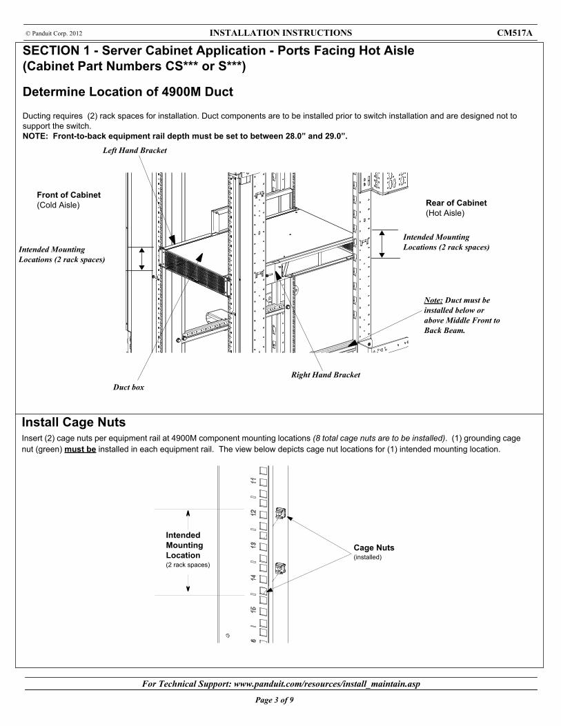
Left Hand Bracket
Intended Mounting Locations (2 rack spaces)
Cage Nuts(installed)
Intended Mounting Location(2 rack spaces)
Install Cage NutsInsert (2) cage nuts per equipment rail at 4900M component mounting locations (8 total cage nuts are to be installed). (1) grounding cage nut (green) must be installed in each equipment rail. The view below depicts cage nut locations for (1) intended mounting location.
SECTION 1 - Server Cabinet Application - Ports Facing Hot Aisle (Cabinet Part Numbers CS*** or S***)
Determine Location of 4900M Duct
Ducting requires (2) rack spaces for installation. Duct components are to be installed prior to switch installation and are designed not to support the switch.NOTE: Front-to-back equipment rail depth must be set to between 28.0” and 29.0”.
Front of Cabinet(Cold Aisle) Rear of Cabinet
(Hot Aisle)
Intended Mounting Locations (2 rack spaces)
Right Hand BracketDuct box
Note: Duct must be installed below or above Middle Front to Back Beam.

For Technical Support: www.panduit.com/resources/install_maintain.asp
INSTALLATION INSTRUCTIONS © Panduit Corp. 2012 CM517A
Page 4 of 9
Left Hand Bracket Installation Loosen the two nuts for the server adjustment bracket and adjust the bracket to match the distance between the front and rear rails of the Server Cabinet. Align the Left Hand Bracket with the desired rack space, fasten the bracket using (2) #12-24 screws in the front rail and (2) in the rear rail. Tighten nuts on adjustment bracket to lock in place.-Repeat previous steps for Right Hand Bracket.
Left Hand Bracket
Front of Cabinet(Cold Aisle)
Front of Cabinet(Cold Aisle)
Rear of Cabinet(Hot Aisle)
#12-24 screw (2)
#12-24 screw (2)
Rear of Cabinet(Hot Aisle)
Right hand bracket
#12-24 screw (2)Note: Green Grounding Screw must go in Green Grounding Cage Nut.
#12-24 screw (2)
Server Adjustment Brackets
Server Adjustment Brackets
For Technical Support: www.panduit.com/resources/install_maintain.asp
INSTALLATION INSTRUCTIONS © Panduit Corp. 2012 CM517A
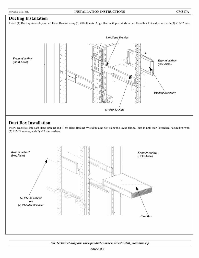
Ducting Installation Install (1) Ducting Assembly to Left Hand Bracket using (3) #10-32 nuts. Align Duct with pem studs in Left Hand bracket and secure with (3) #10-32 nuts.
Page 5 of 9
Left Hand Bracket
Duct Box
Ducting Assembly
Front of cabinet(Cold Aisle)
Rear of cabinet(Hot Aisle)
Duct Box Installation Insert Duct Box into Left Hand Bracket and Right Hand Bracket by sliding duct box along the lower flange. Push in until stop is reached, secure box with (2) #12-24 screws, and (2) #12 star washers.
(3) #10-32 Nuts
Front of cabinet(Cold Aisle) Rear of cabinet
(Hot Aisle)
(2) #12-24 Screwsand
(2) #12 Star Washers

For Technical Support: www.panduit.com/resources/install_maintain.asp
INSTALLATION INSTRUCTIONS © Panduit Corp. 2012 CM517A
Page 6 of 9
Left Hand Bracket
Intended Mounting Locations (2 rack spaces)
SECTION 2 - Switch Cabinet Application - Ports Facing Cold Aisle(Cabinet Part Numbers N*** or CN***)
Determine Location of Duct
Ducting requires (2) rack spaces for installation. 4900M Duct components are to be installed prior to switch installation and are designed not to support the switch. NOTE: Front-to-back equipment rail depth must be set to between 24.5” and 26.0”
Front of Cabinet(Cold Aisle) Rear of Cabinet
(Hot Aisle)
Intended Mounting Locations (2 rack spaces)
Right Hand Bracket
Duct box Note: Duct must be installed below or above Middle Front to Back Beam.
For Technical Support: www.panduit.com/resources/install_maintain.asp
INSTALLATION INSTRUCTIONS © Panduit Corp. 2012 CM517A
Page 7 of 9
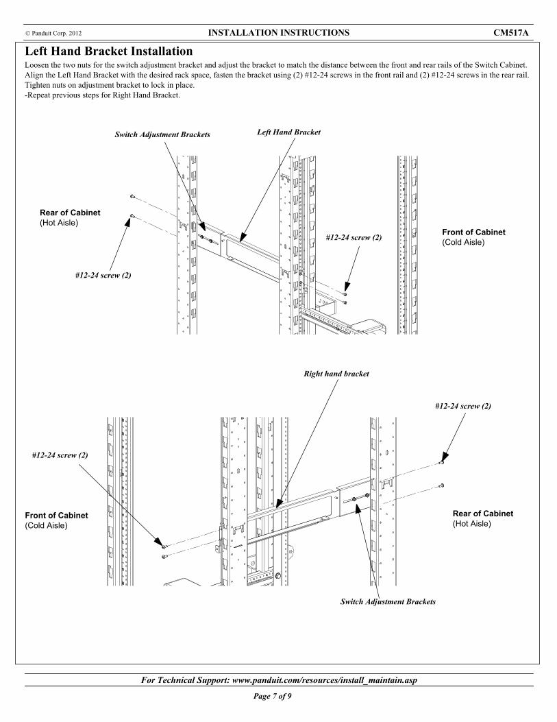
Left Hand Bracket Installation Loosen the two nuts for the switch adjustment bracket and adjust the bracket to match the distance between the front and rear rails of the Switch Cabinet. Align the Left Hand Bracket with the desired rack space, fasten the bracket using (2) #12-24 screws in the front rail and (2) #12-24 screws in the rear rail. Tighten nuts on adjustment bracket to lock in place.-Repeat previous steps for Right Hand Bracket.
Left Hand Bracket
Front of Cabinet(Cold Aisle)
Front of Cabinet(Cold Aisle)
Rear of Cabinet(Hot Aisle)
#12-24 screw (2)
#12-24 screw (2)
Rear of Cabinet(Hot Aisle)
Right hand bracket
#12-24 screw (2)
Switch Adjustment Brackets
Switch Adjustment Brackets
#12-24 screw (2)

For Technical Support: www.panduit.com/resources/install_maintain.asp
INSTALLATION INSTRUCTIONS © Panduit Corp. 2012 CM517A
Ducting Installation Install (1) Ducting Assembly to Right Hand Bracket using (3) #10-32 nuts. Align Duct with pem studs in Right Hand bracket and secure with (3) #10-32 nuts.
Page 8 of 9
Right Hand Bracket
Ducting Assembly
(3) #10-32 Nuts
Front of cabinet(Cold Aisle)
Rear of cabinet(Hot Aisle)
For Technical Support: www.panduit.com/resources/install_maintain.asp
INSTALLATION INSTRUCTIONS © Panduit Corp. 2012 CM517A
Page 9 of 9
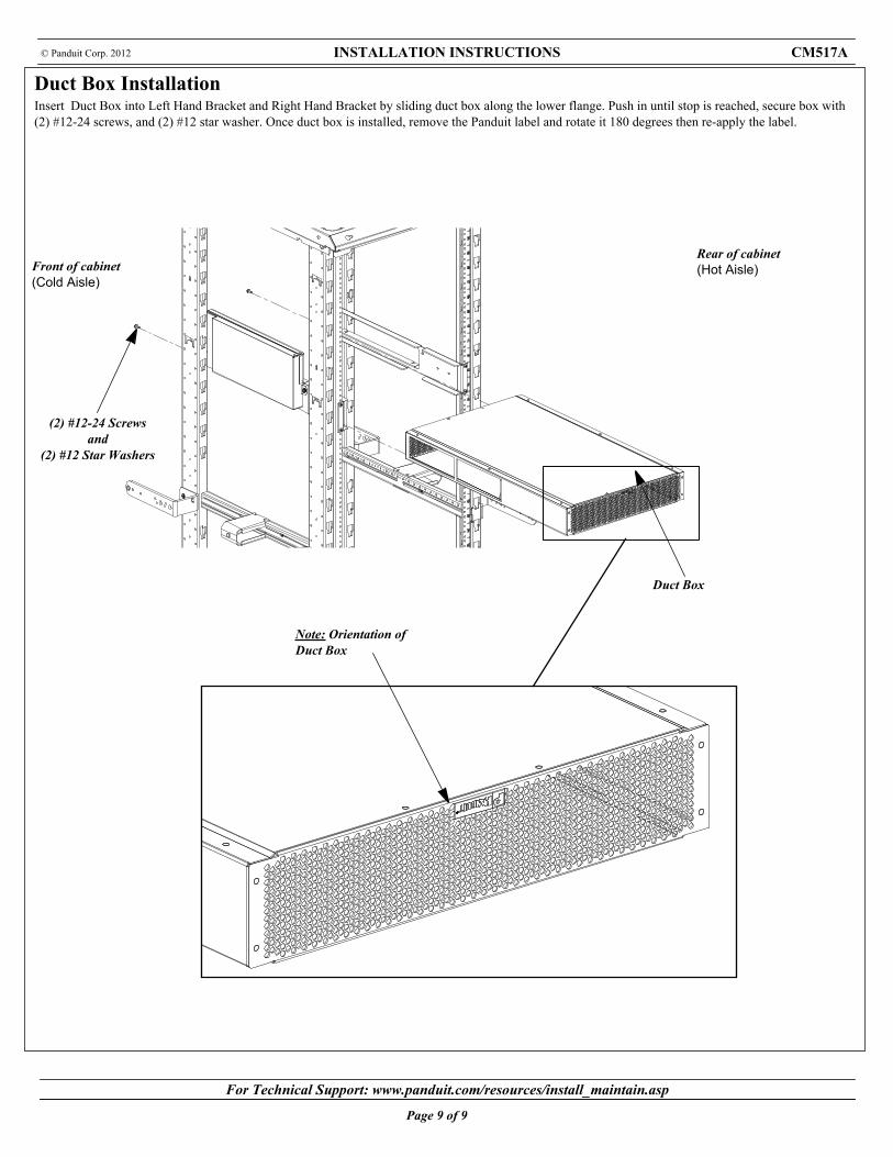
Duct Box
Front of cabinet(Cold Aisle)
Rear of cabinet(Hot Aisle)
Duct Box Installation Insert Duct Box into Left Hand Bracket and Right Hand Bracket by sliding duct box along the lower flange. Push in until stop is reached, secure box with (2) #12-24 screws, and (2) #12 star washer. Once duct box is installed, remove the Panduit label and rotate it 180 degrees then re-apply the label.
Note: Orientation of Duct Box
(2) #12-24 Screwsand
(2) #12 Star Washers