dte energy implementation of community energy storage
TRANSCRIPT

DTE Energy Implementation of Community Energy Storage System for Grid Support
Haukur (Hawk) Asgeirsson, PE Manager - Power Systems Technologies September 23, 2015
1
Disclaimer
DOE OE supported under award DE-OE0000229 "This report was prepared as an account of work sponsored by an agency of the United States Government. Neither the United States Government nor any agency thereof, nor any of their employees, makes any warranty, express or implied, or assumes any legal liability or responsibility for the accuracy, completeness, or usefulness of any information, apparatus, product, or process disclosed, or represents that its use would not infringe privately owned rights. Reference herein to any specific commercial product, process, or service by trade name, trademark, manufacturer, or otherwise does not necessarily constitute or imply its endorsement, recommendation, or favoring by the United States Government or any agency thereof. The views and opinions of authors expressed herein do not necessarily state or reflect those of the United States Government or any agency thereof.“
2

Project Overview
• First large utility scale community energy storage (CES) project on one circuit (1 MW of storage)
• Aggregation of CES using a Distributed Resources System Operation Center (DERMS)
• Using utility industry protocol (DNP3) • Determining economic value of storage on a
distribution circuit in MISO market • Built and deployed secondary use EV batteries • Integration of energy storage and PV
3
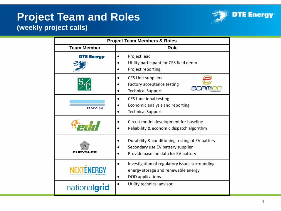
Project Team and Roles (weekly project calls)
4
Project Team Members & Roles Team Member Role
• Project lead • Utility participant for CES field demo • Project reporting
• CES Unit suppliers • Factory acceptance testing • Technical Support
• CES functional testing • Economic analysis and reporting • Technical Support
• Circuit model development for baseline • Reliability & economic dispatch algorithm
• Durability & conditioning testing of EV battery • Secondary use EV battery supplier • Provide baseline data for EV battery
• Investigation of regulatory issues surrounding energy storage and renewable energy
• DOD applications • Utility technical advisor

CES System Overview
• Eighteen new units installed – One was installed in training yard – Developed engineering documents,
installation and operating procedures – 17 on one distribution circuit – IEEE 1547 certification
• Two repurposed EV battery systems demonstrating secondary-use application
• 500 kW of storage co-located with 500 kW PV
5
CES Parameters
Value
Power 25 kW
Energy 50 kWh
Voltage 240/120V AC
Cells Li-Ion
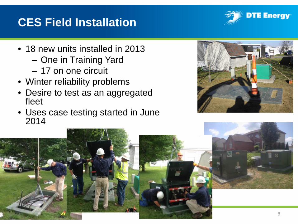
CES Field Installation
• 18 new units installed in 2013 – One in Training Yard – 17 on one circuit
• Winter reliability problems • Desire to test as an aggregated
fleet • Uses case testing started in June
2014
6

Large Storage and PV Integration
• Large storage system with PV – 500 kW PV – 500 kW Li-ion Storage-(250kWh)
• Located at MCCC • Common 480 volt bus with 2-250 kW
PV inverters • 500 kVA Trf at 13.2 kV - Export limited
7
8
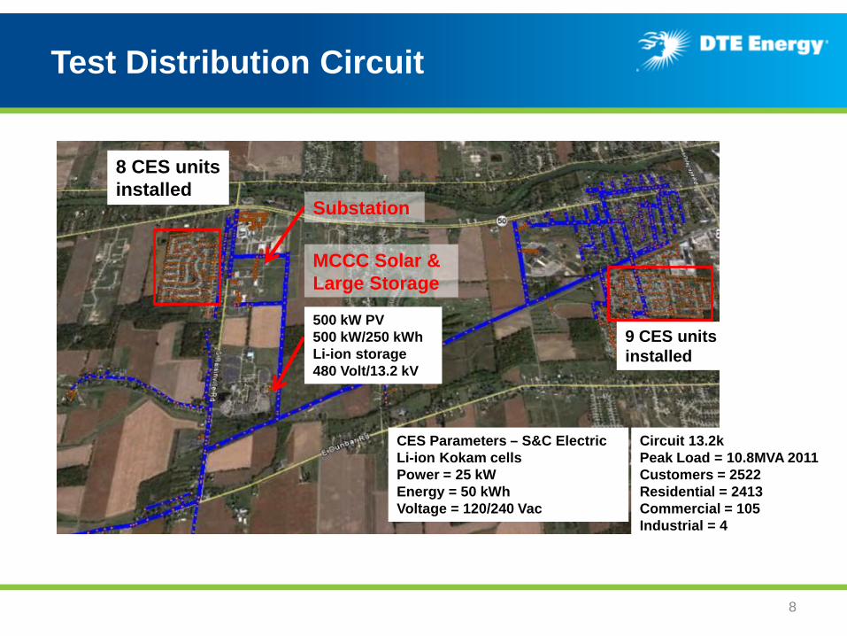
Test Distribution Circuit
8 CES units installed
Substation
MCCC Solar & Large Storage
9 CES units installed
500 kW PV 500 kW/250 kWh Li-ion storage 480 Volt/13.2 kV
CES Parameters – S&C Electric Li-ion Kokam cells Power = 25 kW Energy = 50 kWh Voltage = 120/240 Vac
Circuit 13.2k Peak Load = 10.8MVA 2011 Customers = 2522 Residential = 2413 Commercial = 105 Industrial = 4
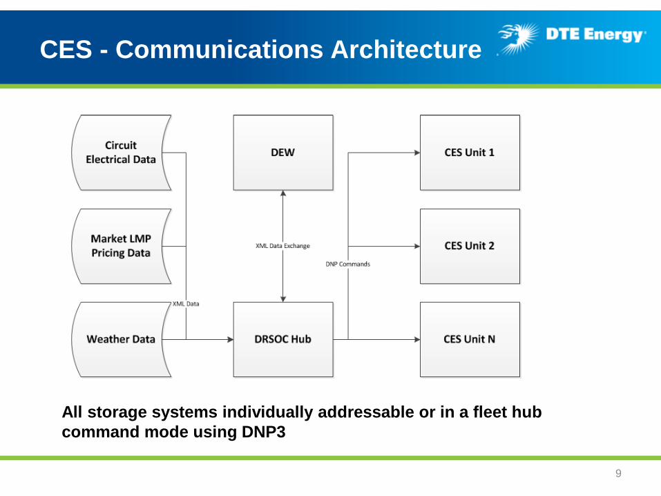
CES - Communications Architecture
9
All storage systems individually addressable or in a fleet hub command mode using DNP3

DTE Energy DERMS
10
DMS
Sensors, Switches, Capacitors,
Regulators, LTC
MDMS OMS
DR-SOC
SOLAR BATTERY PEV
Enterprise Integration
GIS
SCADA / Field Networks
PI
ICCP
Field Communication Network or APN cellular
DNP3 Master
Etc.

11
CES Communication
DRSOCDatabase
XML PosterTool
Memcache Database
DRSOCHub
CES1
CES2
...
CES17
DNP3
DNP3
• DNP3 Master in DR-SOC
• Cell APN communication
• CES Display includes
• Utility load and voltage
• Customers load and voltage
• Inverter data
• Battery data
• System Status and Alarms
• Graph can display any variable

CES Test Plan - Modes of operation document
12
Demonstrated capabilities • Voltage support • VAR support • Islanding during outages • Frequency regulation
(AGC) • Renewable energy time
shift • Circuit peak shaving • Discharge during high LMP
price • Circuit model commands
(DEW Services)

Use case: Circuit Peak Shaving
13
24 hour profile. Light blue=Total circuit load. Dark blue=Load from system. Red=CES fleet. Green=MCCC battery.
kW d
eman
d
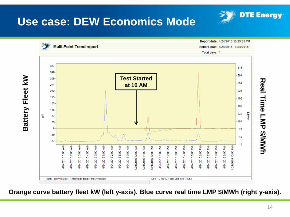
Use case: DEW Economics Mode
14
Orange curve battery fleet kW (left y-axis). Blue curve real time LMP $/MWh (right y-axis).
Bat
tery
Fle
et k
W R
eal Time LM
P $/MW
h
Test Started at 10 AM
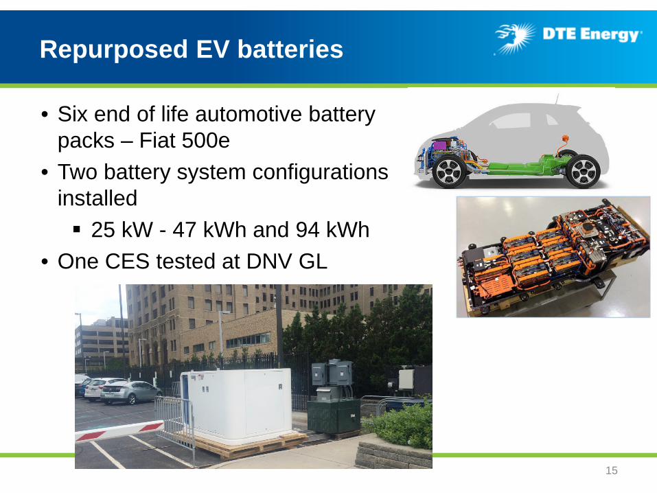
Repurposed EV batteries
• Six end of life automotive battery packs – Fiat 500e
• Two battery system configurations installed 25 kW - 47 kWh and 94 kWh
• One CES tested at DNV GL
15
Remaining work & some lessons learned
• Remaining work – Using EPRI Energy Storage Valuation Tool to perform sensitivity
analysis – Initial draft report in October – Final report to DOE early December
• Lesson learned
– Change in energy storage supplier – Technology reliability maturity (TRL 6-7) – Automotive example – Reliability of hardware and software – Integration of communication systems – Physical location of CES
16
Backup slides
17

Sample test reports
• DNV KEMA Powertest – Round Trip Efficiency – Peak Shaving profile test – Frequency Regulation Profile Test – Islanding Test – Harmonic Analysis
• S&C Electric commissioned IEEE 1547 certification – Passed
– Removed conditional Relay Engineering approval
• DNV KEMA cost effectiveness reports on circuit
– Frequency Regulation – Peak Shaving
• DNV GL Battery degradation testing
18
7.3487 7.3487 7.3487 7.3487 7.3487 7.3487 7.3487 7.3487 7.3487 7.3487 7.3487
x 105
-400
-300
-200
-100
0
100
200
300
400
Time(hours in 4 second intervals)
AGC
Regu
lation
Sign
al

19
CES Communication Hub Command
100 kW Charge

DERMS – Distributed Energy Resource Management System
• Distributed Resources System Operation Center (DR-SOC) • Created a DNP3 master for distributed energy storage system • Smart inverter functionality
20