dta2800™ dta migration planning guide
TRANSCRIPT

DTA2800™DTA MigrationPlanning Guide
NetApp, Inc.495 East Java DriveSunnyvale, CA 94089 U.S.A.Telephone: +1 (408) 822-6000Fax: +1 (408) 822-4501Support telephone: +1 (888) 4-NETAPPDocumentation comments: [email protected] Web: www.netapp.com
Part number: 215-08234_A0August 2013
i
Copyright and trademark information
Copyright information
Copyright © 1994-2013 NetApp, Inc. All rights reserved. Printed in the U.S.
No part of this document covered by copyright may be reproduced in any form or by any means—graphic, electronic, or mechanical, including photocopying, recording, taping, or storage in an electronic retrieval system—without prior written permission of the copyright owner.
Software derived from copyrighted NetApp material is subject to the following license and disclaimer:
THIS SOFTWARE IS PROVIDED BY NETAPP “AS IS” AND WITHOUT ANY EXPRESS OR IMPLIED WARRANTIES, INCLUDING, BUT NOT LIMITED TO, THE IMPLIED WARRANTIES OF MERCHANTABILITY AND FITNESS FOR A PARTICULAR PURPOSE, WHICH ARE HEREBY DISCLAIMED. IN NO EVENT SHALL NETAPP BE LIABLE FOR ANY DIRECT, INDIRECT, INCIDENTAL, SPECIAL, EXEMPLARY, OR CONSEQUENTIAL DAMAGES (INCLUDING, BUT NOT LIMITED TO, PROCUREMENT OF SUBSTITUTE GOODS OR SERVICES; LOSS OF USE, DATA, OR PROFITS; OR BUSINESS INTERRUPTION) HOWEVER CAUSED AND ON ANY THEORY OF LIABILITY, WHETHER IN CONTRACT, STRICT LIABILITY, OR TORT (INCLUDING NEGLIGENCE OR OTHERWISE) ARISING IN ANY WAY OUT OF THE USE OF THIS SOFTWARE, EVEN IF ADVISED OF THE POSSIBILITY OF SUCH DAMAGE.
NetApp reserves the right to change any products described herein at any time, and without notice. NetApp assumes no responsibility or liability arising from the use of products described herein, except as expressly agreed to in writing by NetApp. The use or purchase of this product does not convey a license under any patent rights, trademark rights, or any other intellectual property rights of NetApp.
The product described in this manual may be protected by one or more U.S. patents, foreign patents, or pending applications.
RESTRICTED RIGHTS LEGEND: Use, duplication, or disclosure by the government is subject to restrictions as set forth in subparagraph (c)(1)(ii) of the Rights in Technical Data and Computer Software clause at DFARS 252.277-7103 (October 1988) and FAR 52-227-19 (June 1987).
Trademark information
NetApp, the NetApp logo, Network Appliance, the Network Appliance logo, Akorri, ApplianceWatch, ASUP, AutoSupport, BalancePoint, BalancePoint Predictor, Bycast, Campaign Express, ComplianceClock, Cryptainer, CryptoShred, Data ONTAP, DataFabric, DataFort, Decru, Decru DataFort, DenseStak, Engenio, Engenio logo, E-Stack, FAServer, FastStak, FilerView, FlexCache, FlexClone, FlexPod, FlexScale, FlexShare, FlexSuite, FlexVol, FPolicy, GetSuccessful, gFiler, Go further, faster, Imagine Virtually Anything, Lifetime Key Management, LockVault, Manage ONTAP, MetroCluster, MultiStore, NearStore, NetCache, NOW (NetApp on the Web), Onaro, OnCommand, ONTAPI, OpenKey, PerformanceStak, RAID-DP, ReplicatorX, SANscreen, SANshare, SANtricity, SecureAdmin, SecureShare, Select, Service Builder, Shadow Tape, Simplicity, Simulate ONTAP, SnapCopy, SnapDirector, SnapDrive, SnapFilter, SnapIntegrator, SnapLock, SnapManager, SnapMigrator, SnapMirror, SnapMover, SnapProtect, SnapRestore, Snapshot, SnapSuite, SnapValidator, SnapVault, StorageGRID, StoreVault, the StoreVault logo, SyncMirror, Tech OnTap, The evolution of storage, Topio, vFiler, VFM, Virtual File Manager, VPolicy, WAFL, Web Filer, and XBB are trademarks or registered trademarks of NetApp, Inc. in the United States, other countries, or both.
ii Copyright and trademark information

IBM, the IBM logo, and ibm.com are trademarks or registered trademarks of International Business Machines Corporation in the United States, other countries, or both. A complete and current list of other IBM trademarks is available on the web at www.ibm.com/legal/copytrade.shtml
Apple is a registered trademark and QuickTime is a trademark of Apple, Inc. in the United States and/or other countries. Microsoft is a registered trademark and Windows Media is a trademark of Microsoft Corporation in the United States and/or other countries. RealAudio, RealNetworks, RealPlayer, RealSystem, RealText, and RealVideo are registered trademarks and RealMedia, RealProxy, and SureStream are trademarks of RealNetworks, Inc. in the United States and/or other countries.
All other brands or products are trademarks or registered trademarks of their respective holders and should be treated as such.
NetApp, Inc. is a licensee of the CompactFlash and CF Logo trademarks. NetApp, Inc. NetCache is certified RealSystem compatible.
Copyright and trademark information iii

iv Copyright and trademark information
Table of Contents
Chapter 1 Getting Started . . . . . . . . . . . . . . . . . . . . . . . . . . . . . . . . . 1
Terminology . . . . . . . . . . . . . . . . . . . . . . . . . . . . . . . . . . . 2
Relationship Between Application Data and Physical Storage. . . . . . . . . . 3
LUN Access to a Server . . . . . . . . . . . . . . . . . . . . . . . . . . . . . 4
General Steps for Data Migration . . . . . . . . . . . . . . . . . . . . . . . . 5
Chapter 2 Inventory Checklists . . . . . . . . . . . . . . . . . . . . . . . . . . . . . . 7
Step 1: List the Source and Destination Storage Array. . . . . . . . . . . . . . 8
Step 2: List the Servers Impacted by the Data Migration Project . . . . . . . . 9
Step 3: List the Applications, Mount Points, and Paths to the Physical Devices10
Step 4: List and Create LUN ID Mappings. . . . . . . . . . . . . . . . . . . 11
Step 5: List and Create Fibre Channel Zoning . . . . . . . . . . . . . . . . . 13
Chapter 3 Performance and Downtime . . . . . . . . . . . . . . . . . . . . . . . . . 15
Optimizing Performance During Data Migration . . . . . . . . . . . . . . . 16
Minimizing Downtime for Offline Migration . . . . . . . . . . . . . . . . . 17
Chapter 4 Operating Systems Dependencies . . . . . . . . . . . . . . . . . . . . . . 19
Windows OS . . . . . . . . . . . . . . . . . . . . . . . . . . . . . . . . . . 20
UNIX OS (HP-UX, Linux, AIX, Solaris) . . . . . . . . . . . . . . . . . . . 21
Chapter 5 Checklist Examples . . . . . . . . . . . . . . . . . . . . . . . . . . . . . . 23
Step 1: List the Source and Destination Storage Array. . . . . . . . . . . . . 24
Step 2: List the Servers Impacted by the Data Migration Project . . . . . . . 25
Step 3: List Applications, Mount Points, and Paths to the Physical Device . . 26
Step 4: List and Create LUN ID Mappings. . . . . . . . . . . . . . . . . . . 27
Step 5: List and Create Fibre Channel Zoning . . . . . . . . . . . . . . . . . 28
Table of Contents v
Appendix A Assigning LUNs to the DTA for Data Migration . . . . . . . . . . . . . . 33
Assigning LUNs from an HP MSA2012fc Array . . . . . . . . . . . . . . . 35
Assigning LUNs from an HP MSA1000/1500 Array . . . . . . . . . . . . . 39
Assigning LUNs from an HP 3PAR Array . . . . . . . . . . . . . . . . . . . 42
Assigning LUNs from an HP EVA 4/6/8000 Series Array. . . . . . . . . . . 50
Assigning LUNs from an HDS Array . . . . . . . . . . . . . . . . . . . . . 54
Assigning LUNs from an EMC CLARiiON Array. . . . . . . . . . . . . . . 60
Assigning LUNs from an EMC Symmetrix DMX-4 Array . . . . . . . . . . 66
Assigning LUNs from an IBM DS4K/DS5K/LSI Array . . . . . . . . . . . . 70
Assigning LUNs from an IBM V7000 Array. . . . . . . . . . . . . . . . . . 74
Assigning LUNs from a NetApp FAS2040 System Using FilerView . . . . . 78
Assigning LUNs from a NetApp FAS2040 System Using NetApp System Manager . . . . . . . . . . . . . . . . . . . . . . . . . . . . . . . . . . . 82
Assigning LUNs from a NetApp FAS6280 System Using Data ONTAP Element Manager . . . . . . . . . . . . . . . . . . . . . . . . . . . . . . . . . . . 85
Assigning LUNs from a NetApp E-Series System Using SANtricity Storage Manager . . . . . . . . . . . . . . . . . . . . . . . . . . . . . . . . . . . 88
Assigning LUNs from a NetApp Cluster-Mode Array . . . . . . . . . . . . . 93
Assigning LUNs from a NetApp E-Series Array. . . . . . . . . . . . . . . . 98
Assigning LUNs from a NetApp FAS iSCSI Array . . . . . . . . . . . . . .104
Assigning LUNs from a Xiotech Emprise 5000 Array . . . . . . . . . . . . .109
Assigning LUNs from a Xiotech Magnitude 3D 4000 Array . . . . . . . . .111
Assigning LUNs from an ETERNUS DX440 Array . . . . . . . . . . . . . .114
Assigning LUNs from an ETERNUS DX8400 Array . . . . . . . . . . . . .119
Index . . . . . . . . . . . . . . . . . . . . . . . . . . . . . . . . . . . . . .125
vi Table of Contents
Chapter 1: Getting Started
1
Getting StartedIn a typical storage area network (SAN), the storage array serves one or more servers. When data is migrated from a source LUN to a destination LUN on a different storage array or the same storage array, it is important to understand:
◆ Which applications and servers (or cluster) are affected?
◆ How is application data related to a physical storage?
◆ How does the server access old and new physical storage?
A single blade of the DTA2800 can deliver up to 4TB/hr. migration rate. Following the suggestions outlined in this guide will enable performance of most migration jobs using simple offline migration, while meeting application downtime requirements. Thus, it removes the complexity of performing online data migration using other data migration tools.
1
Terminology
This guide uses the following terms:
◆ Mount point: A node or a directory where application data is stored.
◆ Volume: A single, logical presentation of one or more physical disks.
◆ Physical disk: The raw disk device discovered and configured in the operating system. The object represented in the operating system is usually associated to a LUN on a storage array.
◆ Multipathing software: The LUN may be accessed through multiple ports on a storage array. Each port of a storage array may be accessed through multiple ports (adapters) in the server. Multipathing software in the host manages the multiple paths to a LUN.
2 Terminology

Relationship Between Application Data and Physical Storage
Successful data migration requires an understanding of the relationship between the application data and the physical device (LUN).
Typically, the application accesses the data using a mount point. For example:
◆ The Windows® SharePoint® application accesses its data through a mount point F:\Sharepoint.
◆ The Oracle® application running on a HP-UX (UNIX) host accesses its data through a mount point /home/oracle.
◆ The Apache™ Web Server application on a Linux (UNIX) host access its data through a mount point /data/webinfo.
Typically, the administrator creates a mount point on a volume. On Windows, volume refers to a drive letter (for example, D:\ or F:\). On UNIX operating systems, a mount point may be on a volume managed by a logical volume
manager (Veritas™ or native), or a mount point may be directly on a raw device (/dev/rdsk/c0t1d4).
One can create a volume either on a single physical disk or on multiple physical disks. For example, in Windows, drive letter F:\ may span multiple physical disks (Disk2, Disk3, and so on). On UNIX, a Veritas Volume Manager may have a volume /dev/vg-1/vol1 created on three physical disks: /dev/rdsk/c0t1d2, /dev/rdsk/c0t1d3, and /dev/rdsk/c0t1d4.
The physical disk or a raw device is associated with a LUN. For example, in Windows, Disk2 is LUN 5 on a storage array and Disk3 is LUN 6 on a storage array. In UNIX, /dev/rdsk/c0t1d2 is LUN 2 on a storage array and /dev/rdsk/c0t1d3 is LUN 3 on a storage array.
NoteUNIX® operating system in this discussion refers to HP-UX, Linux®, Solaris®,
and AIX®.
Chapter 1: Getting Started 3

LUN Access to a Server
Multipathing software installed on the server typically manages multipaths to a LUN. In a typical SAN:
◆ A single storage array serves multiple servers and provides controlled access to the LUN, often referred to as LUN presentation.
◆ Multiple servers and storage arrays are present. Server access to a storage array is often controlled by name server zoning.
4 LUN Access to a Server

General Steps for Data Migration
To perform a successful Fibre Channel to Fibre Channel offline data migration, follow these recommended steps. For detailed procedures, including online and remote migration, refer to the DTA2800™ DTA Migration User’s Guide.
1. Create a data migration checklist. “Inventory Checklists” provides an explanation of each of the checklists, and “Checklist Examples” shows examples of completed checklists for a specific data migration scenario.
2. Based on the type of migration (offline, online local, or online remote), prepare the zoning of storage arrays, the host server, and the DTA2800. Ensure that the DTA2800 can discover LUNs from the source array and destination array. For zone configuration information, see the DTA2800™ DTA Migration User’s Guide.
3. Configure the storage array(s), host(s), and DTA2800 for migration. This includes configuring array properties, inserting the DTA2800 in the host data path, LUN mapping, and configuring data migration jobs. For detailed instructions, see the DTA2800™ DTA Migration User’s Guide (recommendations in the “Performance” chapter).
4. Migrate the data.
5. Acknowledge data migration jobs after they reach 100 percent complete.
6. Cut over the host server to the destination storage array by adjusting the Fibre Channel zones created in Step 2.
7. Update the LUN presentation from the destination array to the host server.
8. After data is migrated from one storage to another storage, do the following:
9. Update the multipathing software on the server, if necessary.
10. Adjust the mount point for the volume, if necessary. In most cases, volumes are automatically discovered under Windows and UNIX (HP-UX, Linux, Solaris) systems configured with logical volume managers. For details, see “Assigning LUNs to the DTA for Data Migration”.
11. For record keeping, save the migration logs.
12. Prepare the DTA2800 for the next data migration redeployment. To clear project-specific settings, issue the reset mapping command.
Chapter 1: Getting Started 5

6 General Steps for Data Migration
Chapter 2: Inventory Checklists
2
Inventory ChecklistsData migration checklists help the system administrator take inventory of all items affected by a data migration project. This chapter provides a list of servers and applications, and defines relationships of application data to LUNs and how LUNs are accessed through the server. The migration checklists will also help to identify possible changes required on the server after migration.
The tables in this chapter are designed to take proper inventory used for planning data migration, including:
◆ Step 1: List the Source and Destination Storage Array
◆ Step 2: List the Servers Impacted by the Data Migration Project
◆ Step 3: List the Applications, Mount Points, and Paths to the Physical Devices
◆ Step 4: List and Create LUN ID Mappings
◆ Step 5: List and Create Fibre Channel Zoning
7

Step 1: List the Source and Destination Storage Array
The information requested in Table 2-1 can be retrieved from the storage administrator in the data center.
Table 2-1. Storage Array Information
Storage Array
Source or Destination
Firmware Version
Array Management
Software1Number of Con-trollers
WWPN2 (Fibre Channel)
1. The storage array specific software that is used in data migration to present the source LUNs to the DTA2800, and to create destination LUNs to be presented to the DTA2800 and to the server. The array management software also provides the controller and WWPN information for the stor-age array ports.
2. World wide port name of the Fibre Channel array; used in performing zoning in Fibre Channel switch firmware.
8 Step 1: List the Source and Destination Storage Array
Step 2: List the Servers Impacted by the Data Migration Project
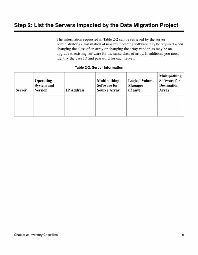
The information requested in Table 2-2 can be retrieved by the server administrator(s). Installation of new multipathing software may be required when changing the class of an array or changing the array vendor, as may be an upgrade to existing software for the same class of array. In addition, you must identify the user ID and password for each server.
Table 2-2. Server Information
Server
Operating System and Version IP Address
Multipathing Software for Source Array
Logical Volume Manager (if any)
Multipathing Software for Destination Array
Chapter 2: Inventory Checklists 9
Step 3: List the Applications, Mount Points, and Paths to the Physical Devices
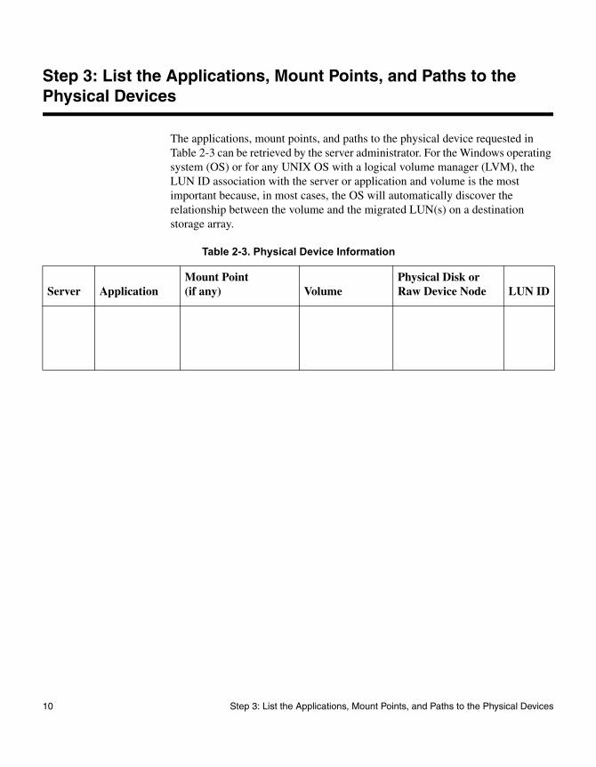
The applications, mount points, and paths to the physical device requested in Table 2-3 can be retrieved by the server administrator. For the Windows operating system (OS) or for any UNIX OS with a logical volume manager (LVM), the LUN ID association with the server or application and volume is the most important because, in most cases, the OS will automatically discover the relationship between the volume and the migrated LUN(s) on a destination storage array.
Table 2-3. Physical Device Information
Server ApplicationMount Point(if any) Volume
Physical Disk or Raw Device Node LUN ID
10 Step 3: List the Applications, Mount Points, and Paths to the Physical Devices

Step 4: List and Create LUN ID Mappings
Create a list of LUNs containing the size and mapping information that shows how the LUNs are seen by the server and the DTA2800, as shown in Table 2-4. Although a specific LUN may be presented at a different LUN ID to a server other than to DTA2800, it is recommended that the same LUN ID is used, if possible.
This practice will be very helpful while creating new LUNs on a destination array, and while presenting source and destination LUNs to DTA2800 data migration service. For operating systems other than Windows, it is highly recommended that source and destination LUNs are the same size.
This step uses the LUN remapping feature of NetApp DTA Manager to map the LUNs to the server through DTA2800. With LUN remapping, you can present LUNs to the DTA2800 at any available ID, without regard for the IDs that are presented to the server. However, if your environment allows it, it is simpler to present the same LUNs to the server through the DTA2800 as presented by the array.
Chapter 2: Inventory Checklists 11
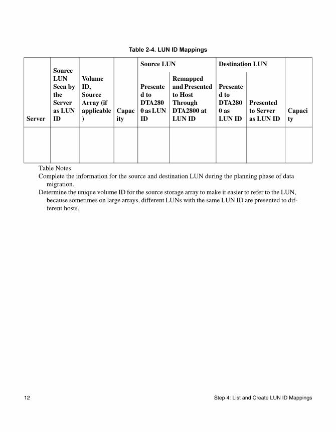
Table 2-4. LUN ID Mappings
Server
Source LUN Seen by the Server as LUN ID
Volume ID, Source Array (if applicable)
Capacity
Source LUN Destination LUN
Capacity
Presented to DTA2800 as LUN ID
Remapped and Presented to Host Through DTA2800 at LUN ID
Presented to DTA2800 as LUN ID
Presented to Server as LUN ID
Table NotesComplete the information for the source and destination LUN during the planning phase of data
migration.Determine the unique volume ID for the source storage array to make it easier to refer to the LUN,
because sometimes on large arrays, different LUNs with the same LUN ID are presented to dif-ferent hosts.
12 Step 4: List and Create LUN ID Mappings
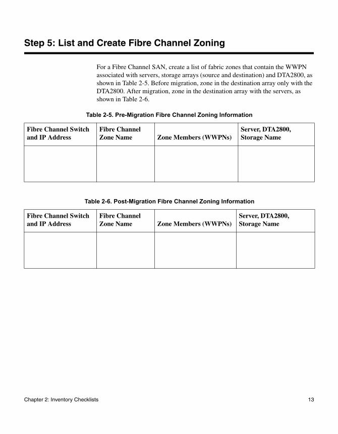
Step 5: List and Create Fibre Channel Zoning
For a Fibre Channel SAN, create a list of fabric zones that contain the WWPN associated with servers, storage arrays (source and destination) and DTA2800, as shown in Table 2-5. Before migration, zone in the destination array only with the DTA2800. After migration, zone in the destination array with the servers, as shown in Table 2-6.
Table 2-5. Pre-Migration Fibre Channel Zoning Information
Fibre Channel Switch and IP Address
Fibre Channel Zone Name Zone Members (WWPNs)
Server, DTA2800, Storage Name
Table 2-6. Post-Migration Fibre Channel Zoning Information
Fibre Channel Switch and IP Address
Fibre Channel Zone Name Zone Members (WWPNs)
Server, DTA2800, Storage Name
Chapter 2: Inventory Checklists 13

14 Step 5: List and Create Fibre Channel Zoning
Chapter 3: Performance and Downtime
3
Performance and DowntimeThis chapter provides recommendations designed to improve performance and minimize downtime during data migration.
15
Optimizing Performance During Data Migration
The DTA2800 uses all available paths to a specified LUN and performs load balancing using all active optimized paths. Therefore, NetApp highly recommends that LUNs are balanced across paths on both array controllers. Best performance is achieved when half of the LUNs are active optimized on the first controller, and the other half are active optimized on the second controller.
Where high availability (HA) configuration as redundant SAN is deployed, NetApp highly recommends the following:
◆ Connect one Fibre Channel port from the DTA2800 blade to one SAN, and connect the other port to the redundant SAN.
◆ Connect Fibre Channel ports from the destination array to both SANs.
◆ Maximize array performance by simultaneously running 4 to 8 active jobs on a single array. The DTA2800 can have up to 256 migration jobs per blade.
◆ Maximize DTA2800 performance by running jobs on both blades.
◆ Balance across two controllers the LUNs used in migration jobs that run simultaneously.
◆ Run test jobs with different I/O sizes to determine what size yields the best performance for your environment.
16 Optimizing Performance During Data Migration
Minimizing Downtime for Offline Migration
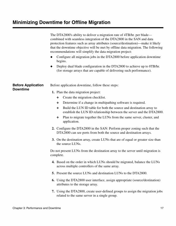
The DTA2800's ability to deliver a migration rate of 4TB/hr. per blade—combined with seamless integration of the DTA2800 in the SAN and data protection features such as array attributes (source/destination)—make it likely that the downtime objective will be met by offline data migration. The following recommendations will simplify the data migration project:
◆ Configure all migration jobs in the DTA2800 before application downtime begins.
◆ Deploy dual blade configuration in the DTA2800 to achieve up to 8TB/hr. (for storage arrays that are capable of delivering such performance).
Before Application Downtime
Before application downtime, follow these steps:
1. Plan the data migration project:
❖ Create the migration checklist.
❖ Determine if a change in multipathing software is required.
❖ Build the LUN ID table for both the source and destination array to establish the LUN ID relationship between the server and the DTA2800.
❖ Plan to migrate together the LUNs from the same server, cluster, and application.
2. Configure the DTA2800 in the SAN: Perform proper zoning such that the DTA2800 can see ports from both the source and destination arrays.
3. On the destination array, create LUNs that are of equal or greater size than the source LUNs.
Do not present LUNs from the destination array to the server until migration is complete.
4. Based on the order in which LUNs should be migrated, balance the LUNs across multiple controllers of the same array.
5. Present the source LUNs and destination LUNs to the DTA2800.
6. Using the DTA2800 user interface, assign appropriate (source/destination) attributes to the storage array.
7. Using the DTA2800, create user-defined groups to assign the migration jobs related to the same server in a single group.
Chapter 3: Performance and Downtime 17

8. Using the user interface wizard, configure migration jobs.
During Application Downtime
During application downtime, follow these steps:
1. Confirm with the storage administrator that the application and server are down, and that the server no longer has access to the storage under migration.
2. Remove the server access to the source storage array by changing the Fibre Channel zoning such that server adapter ports can no longer see the source or destination array ports.
3. If the server is not connected any other storage arrays, consider bringing down the Fibre Channel switch ports to which the server is connected.
4. Start the previously configured migration jobs.
5. If required, install the new multipathing software on the server.
6. After the data is migrated for the specified server or cluster, present the destination LUNs to the server or cluster by changing the fabric zoning and LUN presentation from the array.
7. Reboot the server, and then validate that the new LUNs are seen by the system and that the volumes are mounted on the destination LUNs.
Validating Integrity of the Data
If there is a file system on the LUN, perform a quick file system check by bringing up the application and confirming access to the data.
18 Minimizing Downtime for Offline Migration

Chapter 4: Operating Systems Dependencies
4
Operating Systems DependenciesIf the source array type is different from the destination array type, installation of the new multipathing software associated with the destination array may be required.
NoteDo not expose the destination LUNs to a server until the data migration is complete and server access to the source LUN is removed.
19
Windows OS
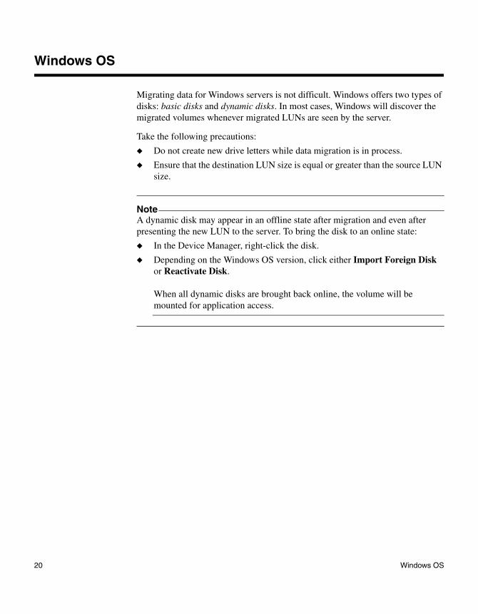
Migrating data for Windows servers is not difficult. Windows offers two types of disks: basic disks and dynamic disks. In most cases, Windows will discover the migrated volumes whenever migrated LUNs are seen by the server.
Take the following precautions:
◆ Do not create new drive letters while data migration is in process.
◆ Ensure that the destination LUN size is equal or greater than the source LUN size.
NoteA dynamic disk may appear in an offline state after migration and even after presenting the new LUN to the server. To bring the disk to an online state:
◆ In the Device Manager, right-click the disk.
◆ Depending on the Windows OS version, click either Import Foreign Disk or Reactivate Disk.
When all dynamic disks are brought back online, the volume will be mounted for application access.
20 Windows OS

UNIX OS (HP-UX, Linux, AIX, Solaris)
On UNIX operating systems—HP-UX, Linux, AIX, and Solaris—If volumes are managed through logical volume managers, follow these general guidelines:
◆ For offline migration, export the volume before migration begins.
◆ For online migration, NetApp DTA Manager exports volumes when the migration job is complete and applications are ready to be moved to the destination array.
◆ Import the volume after migration is complete and destination LUNs are presented to the server.
If volumes are not managed through a logical volume manager in the system, it is very important to follow the pre-migration checklists to identify the physical device node(s) (/dev/rdsk/c0t1d1) on which the volume is mounted. After data migration, the physical device node may change. Change the volume mount such that it now it points to the new physical device (dev/rdsk/c0t2d5).
To discover current active mount points, issue the mount command on the system console.
Some applications, such as the Oracle Cluster File system (OCFS) may directly use the raw devices. Consult the system administrator. OCFS may automatically discover the migrated devices. Follow the procedure listed in OCFS manual.
The destination LUN size must be equal to or greater than that of the source LUN. Expand the destination LUN after the migration is complete and the migrated volume is remounted. (Destination LUN expansion is not supported on Solaris.)
Chapter 4: Operating Systems Dependencies 21

22 UNIX OS (HP-UX, Linux, AIX, Solaris)

Chapter 5: Checklist Examples
5
Checklist ExamplesThis appendix provides examples of completed data migration checklists. These
examples depict a scenario where a customer is upgrading from an old EMC®
CX3-20 storage array to a new HP® EVA 4400 storage array. Three applications and servers are using the CX3-20 array. Each of these three servers has a different operating system. The information shown with bold text in these tables represents changes from the existing configuration.
23

Step 1: List the Source and Destination Storage Array
Table 5-7. Example: Storage Array Information
Storage ArraySource or Destination
Firmware Version
Array Managemen
t Software1
Number of Con-trollers WWPN2 (Fibre Channel)
EMC CX3-20 Source 03.24.040.5.006
Navisphere 2 50-06-01-60-41-e0-18-94
50-06-01-61-41-e0-18-94
50-06-01-62-41-e0-18-94
50-06-01-63-41-e0-18-94
HP EVA 4400 Destination CR0D63xc3p-6000
Command View
2 50-00-1F-E1-50-06-22-A1
50-00-1F-E1-50-06-22-A2
50-00-1F-E1-50-06-22-A2
50-00-1F-E1-50-06-22-A3
50-00-1F-E1-50-06-22-A4
1. The storage array specific software that will be used in data migration to present the source LUNs to the DTA2800, and to create destination LUNs to be presented to the DTA2800 and to the serv-er. The array management software will also provide the controller and WWPN information for the storage array ports.
2. World wide port name of the Fibre Channel array; used in performing zoning in Fibre Channel switch firmware.
24 Step 1: List the Source and Destination Storage Array
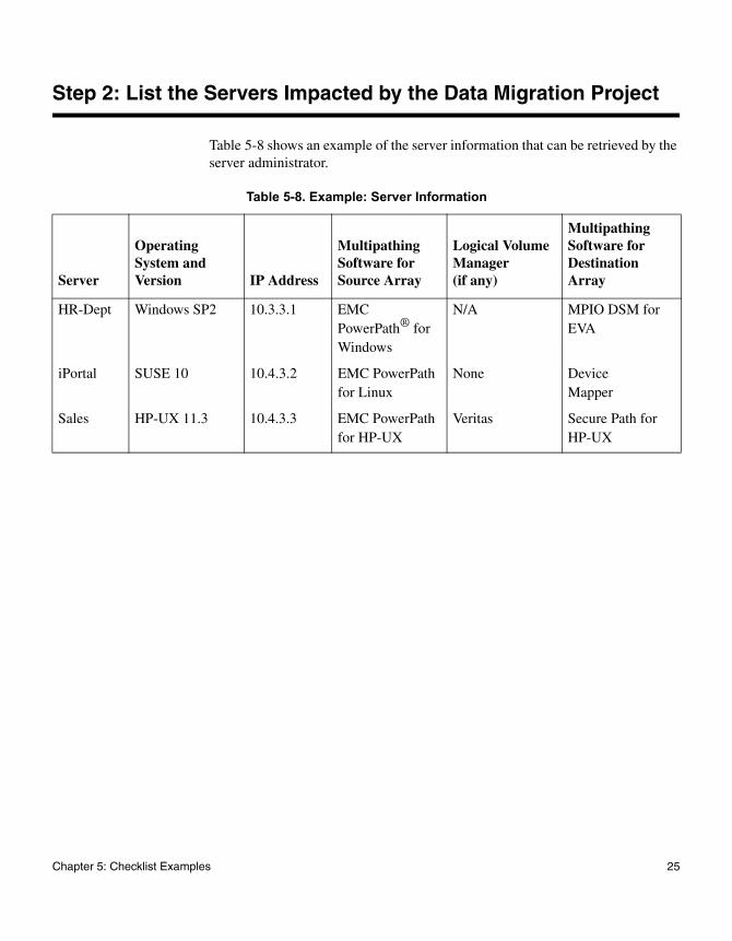
Step 2: List the Servers Impacted by the Data Migration Project
Table 5-8 shows an example of the server information that can be retrieved by the server administrator.
Table 5-8. Example: Server Information
Server
Operating System and Version IP Address
Multipathing Software for Source Array
Logical Volume Manager (if any)
Multipathing Software for Destination Array
HR-Dept Windows SP2 10.3.3.1 EMC PowerPath® for Windows
N/A MPIO DSM for EVA
iPortal SUSE 10 10.4.3.2 EMC PowerPath for Linux
None Device Mapper
Sales HP-UX 11.3 10.4.3.3 EMC PowerPath for HP-UX
Veritas Secure Path for HP-UX
Chapter 5: Checklist Examples 25

Step 3: List Applications, Mount Points, and Paths to the Physical Device
Table 5-9 shows an example of the applications, mount points, and path to the physical device, which can be retrieved from the server administrator.
Table 5-9. Example: Physical Device Information
ServerApplica-tion
Mount Point(if any) Volume
Physical Disk or Raw Device Node LUN ID
HR-Dept Sharepoint F:\Sharepoint F:\ Disk0, Disk1 (Dynamic Disks)
0, 1
iPortal Apache Web Server
/data/webinfo /dev/sdb /dev/sdb 0
Sales Oracle /home/oracle /dev/vg-2/vol2
/dev/rdsk/c0t1d0
/dev/rdsk/c0t1d1
/dev/rdsk/c0t1d2
0, 1, 2
26 Step 3: List Applications, Mount Points, and Paths to the Physical Device

Step 4: List and Create LUN ID Mappings
Table 5-10 shows LUNs presented to the DTA2800 at LUN IDs that are different from the IDs presented to the server. You can later use the LUN remapping feature to present LUNs to the server with the original LUN IDs. Through the DTA2800, a different LUN from a storage array is presented as the same LUN ID (2) on two different servers: HR-Dept and iPortal.
Table 5-10. Example: LUN ID Mappings
Server
Source LUN Seen by the Server as LUN ID
Volume ID, Source Array (if applicable)
Capacity
Source LUN Destination LUN
Capacity
Presented to DTA2800 as LUN ID
Remapped and Presented to Host Through DTA2800 at LUN ID
Presented to DTA2800 as LUN ID
Presented to Server as LUN ID
HR-Dept.
0
1
1
2
100GB
250GB
0
1
0
1
0
1
0
1
200GB
500GB
iPortal 0 3 250GB
2 0 2 0 250GB
Sales 0
1
2
4
5
6
300GB
300GB
300GB
3
4
5
0
1
2
3
4
5
0
1
2
300GB
300GB
300GB
Chapter 5: Checklist Examples 27

Step 5: List and Create Fibre Channel Zoning
Table 5-11 assumes a redundant configuration, meaning there are:
◆ Two Fibre Channel switches
◆ Multiple servers, each with two adapter ports
◆ One storage array with two controllers
◆ Four ports per controller
28 Step 5: List and Create Fibre Channel Zoning

Table 5-12 shows new Fibre Channel zones information to configure DTA2800 for data migration and to migrate the data. The DTA2800 Fibre Channel ports are configured with source and destination arrays.
Table 5-11. Example A: Pre-Migration Fibre Channel Zoning Information
Fibre Channel Switch and IP Address
Fibre Channel Zone Name Zone Members (WWPNs)
Server, DTA2800, Storage Name
FC-SW-1
10.5.3.1
Zone-A 21-00-00-C0-DD-C0-8A-D7
21-00-00-C0-DD-C0-55-57
21-00-00-C0-DD-C0-60-66
50-06-01-60-41-E0-18-94
50-06-01-62-41-E0-18-94
HR-Dept: P1
iPortal: P1
Sales: P1
SRC-Array-ABC: P1
SRC-Array-ABC: P3
FC-SW-2
10.5.3.2
Zone-B 21-00-00-C0-DD-C0-8A-D8
21-00-00-C0-DD-C0-55-58
21-00-00-C0-DD-C0-60-67
50-06-01-61-41-E0-18-94
50-06-01-63-41-E0-18-94
HR-Dept: P2
iPortal: P2
Sales: P2
SRC-Array-ABC: P2
SRC-Array-ABC: P4
Table 5-12. Example B: Pre-Migration Fibre Channel Zoning Information
Fibre Channel Switch and IP Address
Fibre Channel Zone Name Zone Members (WWPNs)
Server, DTA2800, Storage Name
FC-SW-1
10.5.3.1
Zone-A-DM 21-00-00-C0-DD-C0-88-81
50-06-01-60-41-E0-18-94
50-06-01-62-41-E0-18-94
50-00-1F-E1-50-06-22-A1
50-00-1F-E1-50-06-22-A2
DTA2800, FC1
SRC-Array-ABC: P1
SRC-Array-ABC: P3
DEST-Array-XYZ: P1
DEST-Array-XYZ: P3
Chapter 5: Checklist Examples 29

FC-SW-1
10.5.3.2
Zone-B-DM 21-00-00-C0-DD-C0-88-82
50-06-01-61-41-E0-18-94
50-06-01-63-41-E0-18-94
50-00-1F-E1-50-06-22-A8
50-00-1F-E1-50-06-22-A9
DTA2800: FC2
SRC-Array-ABC: P2
SRC-Array-ABC: P4
DEST-Array-XYZ: P2
DEST-Array-XYZ: P4
Table 5-12. Example B: Pre-Migration Fibre Channel Zoning Information (Continued)
Fibre Channel Switch and IP Address
Fibre Channel Zone Name Zone Members (WWPNs)
Server, DTA2800, Storage Name
30 Step 5: List and Create Fibre Channel Zoning

Table 5-13 shows an example of post-migration Fibre Channel zoning information.
Table 5-13. Example: Post-Migration Fibre Channel Zoning Information
Fibre Channel Switch and IP Address
Fibre Channel Zone Name Zone Members (WWPNs)
Server, DTA2800, Storage Name
FC-SW-1/10.5.3.1 Zone-A 21-00-00-C0-DD-C0-8A-D7
21-00-00-C0-DD-C0-55-57
21-00-00-C0-DD-C0-60-66
50-00-1F-E1-50-06-22-A1
50-00-1F-E1-50-06-22-A2
HR-Dept: P1
iPortal: P1
Sales: P1
DEST-Array-XYZ: P1
DEST-Array-XYZ: P3
FC-SW-2/10.5.3.2 Zone-B 21-00-00-C0-DD-C0-8A-D8
21-00-00-C0-DD-C0-55-58
21-00-00-C0-DD-C0-60-67
50-00-1F-E1-50-06-22-A8
50-00-1F-E1-50-06-22-A9
HR-Dept: P2
iPortal: P2
Sales: P2
DEST-Array-XYZ: P2
DEST-Array-XYZ: P4
Chapter 5: Checklist Examples 31

32 Step 5: List and Create Fibre Channel Zoning

Appendix A: Assigning LUNs to the DTA for Data Migration
A
Assigning LUNs to the DTA for Data MigrationFor successful completion of data migration, assign source and destination LUNs to the DTA2800 using storage array management tools. The DTA2800 appears as a host to the array controller. When you register the DTA2800 port WWNs, you must set the correct attributes. Ensure that you register all WWNs belonging a specific virtual port (VP) group under a single host entity.
This appendix provides procedures for using some of the array management tools to assign LUNs, including:
◆ “Assigning LUNs from an HP MSA2012fc Array” on page A-35
◆ “Assigning LUNs from an HP MSA1000/1500 Array” on page A-39
◆ “Assigning LUNs from an HP 3PAR Array” on page A-42
◆ “Assigning LUNs from an HP EVA 4/6/8000 Series Array” on page A-50
◆ “Assigning LUNs from an HDS Array” on page A-54
◆ “Assigning LUNs from an EMC CLARiiON Array” on page A-60
◆ “Assigning LUNs from an EMC Symmetrix DMX-4 Array” on page A-66
◆ “Assigning LUNs from an IBM DS4K/DS5K/LSI Array” on page A-70
◆ “Assigning LUNs from an IBM V7000 Array” on page A-74
◆ “Assigning LUNs from a NetApp FAS2040 System Using FilerView” on page A-78
◆ “Assigning LUNs from a NetApp FAS2040 System Using NetApp System Manager” on page A-82
◆ “Assigning LUNs from a NetApp FAS6280 System Using Data ONTAP Element Manager” on page A-85
◆ “Assigning LUNs from a NetApp E-Series System Using SANtricity Storage Manager” on page A-88
◆ “Assigning LUNs from a NetApp Cluster-Mode Array” on page A-93
◆ “Assigning LUNs from a NetApp E-Series Array” on page A-98
◆ “Assigning LUNs from a NetApp FAS iSCSI Array” on page A-104
◆ “Assigning LUNs from a Xiotech Emprise 5000 Array” on page A-109
NoteFor online migration for an HP-UX host, ensure that the host platform and node setting for the DTA2800 are exactly the same as the HP-UX host settings in the respective array management software.
33

◆ “Assigning LUNs from a Xiotech Magnitude 3D 4000 Array” on page A-111
◆ “Assigning LUNs from an ETERNUS DX440 Array” on page A-114
◆ “Assigning LUNs from an ETERNUS DX8400 Array” on page A-119
34 Assigning LUNs to the DTA for Data Migration
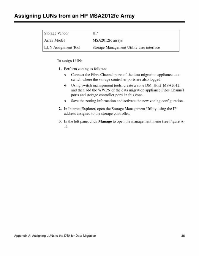
Assigning LUNs from an HP MSA2012fc Array
To assign LUNs:
1. Perform zoning as follows:
❖ Connect the Fibre Channel ports of the data migration appliance to a switch where the storage controller ports are also logged.
❖ Using switch management tools, create a zone DM_Host_MSA2012, and then add the WWPN of the data migration appliance Fibre Channel ports and storage controller ports in this zone.
❖ Save the zoning information and activate the new zoning configuration.
2. In Internet Explorer, open the Storage Management Utility using the IP address assigned to the storage controller.
3. In the left pane, click Manage to open the management menu (see Figure A-1).
Storage Vendor HP
Array Model MSA2012fc arrays
LUN Assignment Tool Storage Management Utility user interface
Appendix A: Assigning LUNs to the DTA for Data Migration 35

Figure A-1. Viewing the Storage Management Utility
4. In the left pane, click VOLUME MANAGEMENT, click volume mapping, and then click manage host list.
Figure A-2 shows the WWPN of the data migration appliance in the right pane.
36 Assigning LUNs from an HP MSA2012fc Array

Figure A-2. Viewing WWPNs in Storage Management Utility
5. In the Manufacturer Nickname box, type DM-Host.
6. To accept and save the changes, click Update.
7. In the left pane, click VOLUME MANAGEMENT, click volume mapping, and then click map hosts to volume.
8. In the right pane, click the LUN to be assigned to the data migration appliance (see Figure A-3).
Appendix A: Assigning LUNs to the DTA for Data Migration 37

Figure A-3. Selecting LUNs in Storage Management Utility
9. In the Assign Host Access Privileges table, select the DM-Host in the Host WWN - Name list, and then enter the appropriate, planned LUN ID.
10. To accept and save the LUN assignment, click Map it.
11. Refresh the data migration user interface to see if the LUN assignment is reflected properly, and that the appropriate array entity appears under FC Array. (You may need to click the Refresh button several times to correctly reflect the changes.)
38 Assigning LUNs from an HP MSA2012fc Array

Assigning LUNs from an HP MSA1000/1500 Array
To assign LUNs:
1. Perform zoning as follows:
❖ Connect the Fibre Channel ports of the data migration appliance to a switch where the storage controller ports are also logged.
❖ Using switch management tools, create a zone DM_Host_MSA1000, and then add the WWPN of the data migration appliance Fibre Channel ports and storage controller ports in this zone.
❖ Save the zoning information and activate the new zoning configuration.
2. Open the Array Configuration Utility.
The Configure Available Device(s) window appears, as shown in Figure A-4.
Storage Vendor HP
Array Model MSA 1000/1500 arrays
LUN Assignment Tool Storage Navigator Modular user interface
Appendix A: Assigning LUNs to the DTA for Data Migration 39

Figure A-4. Configure Available Device(s)
3. In the right pane under Common Tasks, click Selective Storage Presentation, and then click Enable.
A list of the WWPNs seen by the MSA controller appears, as shown in Figure A-5.
Figure A-5. Entering a Connection Name
4. Enter DM-Host as the connection name for the data migration appliance WWPN.
5. From the list box, select Windows as the host mode value, as shown in Figure A-6.
40 Assigning LUNs from an HP MSA1000/1500 Array

Figure A-6. Selecting the Host Mode
6. Select the LUNs to be assigned to the DM-Host by checking the box associated with the previously planned LUNs, as shown in Figure A-7.
Figure A-7. Selecting LUNs
7. To accept and save the LUN assignment, click OK.
8. Refresh the data migration user interface to see if the LUN assignment is reflected properly, and that the appropriate array entity appears under FC Array. (You may need to click the Refresh button several times to correctly reflect the changes.)
Appendix A: Assigning LUNs to the DTA for Data Migration 41
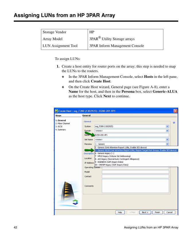
Assigning LUNs from an HP 3PAR Array
To assign LUNs:
1. Create a host entity for router ports on the array; this step is needed to map the LUNs to the routers.
❖ In the 3PAR Inform Management Console, select Hosts in the left pane, and then click Create Host.
❖ On the Create Host wizard, General page (see Figure A-8), enter a Name for the host, and then in the Persona box, select Generic-ALUA as the host type. Click Next to continue.
Storage Vendor HP
Array Model 3PAR® Utility Storage arrays
LUN Assignment Tool 3PAR Inform Management Console
42 Assigning LUNs from an HP 3PAR Array
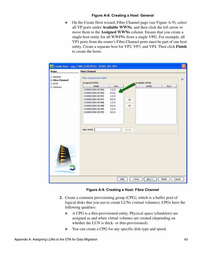
Figure A-8. Creating a Host: General
❖ On the Create Host wizard, Fibre Channel page (see Figure A-9), select all VP ports under Available WWNs, and then click the left arrow to move them to the Assigned WWNs column. Ensure that you create a single host entity for all WWPNs from a single VPG. For example, all VP1 ports from the router’s Fibre Channel ports must be part of one host entity. Create a separate host for VP2, VP3, and VP4. Then click Finish to create the hosts.
Figure A-9. Creating a Host: Fibre Channel
2. Create a common provisioning group (CPG), which is a buffer pool of logical disks that you use to create LUNs (virtual volumes). CPGs have the following qualities:
❖ A CPG is a thin-provisioned entity. Physical space (chunklets) are assigned as and when virtual volumes are created (depending on whether the LUN is thick- or thin-provisioned).
❖ You can create a CPG for any specific disk type and speed.
Appendix A: Assigning LUNs to the DTA for Data Migration 43

❖ You can assign to the CPG a RAID group that ensures that any LUN (virtual volume) created using this CPG has an assigned RAID level.
❖ You can create multiple CPGs without consuming physical space on disks.
❖ In the 3PAR Inform Management Console, select Provisioning in the left pane, and then click Create CPG.
❖ On the Create CPG wizard, General page (see Figure A-10), enter a Name for the CPG, and then select values for the Device Type, Device Speed, RAID Type, and Set Size. Select the Show advanced options panel(s) check box, and then click Next to continue.
Figure A-10. Creating a CPG: General
❖ On the Create CPG wizard, Allocation Settings page (see Figure A-11), either accept the default Availability setting, or select either Port, Magazine, or Cage, depending on the available array model and disk types. Do not change the default Step Size and Preferred Chunklets settings. Click Next to continue.
44 Assigning LUNs from an HP 3PAR Array
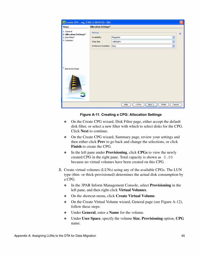
Figure A-11. Creating a CPG: Allocation Settings
❖ On the Create CPG wizard, Disk Filter page, either accept the default disk filter, or select a new filter with which to select disks for the CPG. Click Next to continue.
❖ On the Create CPG wizard, Summary page, review your settings and then either click Prev to go back and change the selections, or click Finish to create the CPG.
❖ In the left pane under Provisioning, click CPGs to view the newly created CPG in the right pane. Total capacity is shown as 0.00 because no virtual volumes have been created on this CPG.
3. Create virtual volumes (LUNs) using any of the available CPGs. The LUN type (thin- or thick-provisioned) determines the actual disk consumption by a CPG.
❖ In the 3PAR Inform Management Console, select Provisioning in the left pane, and then right-click Virtual Volumes.
❖ On the shortcut menu, click Create Virtual Volume.
❖ On the Create Virtual Volume wizard, General page (see Figure A-12), follow these steps:
❖ Under General, enter a Name for the volume.
❖ Under User Space, specify the volume Size, Provisioning option, CPG name.
Appendix A: Assigning LUNs to the DTA for Data Migration 45

❖ For thin-provisioned volumes, set the Allocation Warning based on the percentage of available space.
❖ Under Grouping, specify the Count (number of virtual volumes to be created at one time within the set). 3PAR automatically enters a Set Name.
❖ Click Next to continue.
Figure A-12. Creating a Virtual Volume: General
❖ On the Create Virtual Volume wizard, Copy Space Settings page, select <none> for the CPG copy space. (Copy space creates a backup of the same virtual volumes, which you can store on a different CPG.) Click Next to review the virtual volume configuration.
❖ On the Create Virtual Volume wizard, Summary page, review your settings and then either click Prev to go back and change the selections, or click Finish to create the virtual volume.
❖ In the left pane under Provisioning, click Virtual Volumes to view the newly created volume details in the right pane. Thin-provisioned
46 Assigning LUNs from an HP 3PAR Array

volumes will show minimal used space (by default, they occupy some space for administrative data).
4. Map a virtual volume to the host as follows:
❖ In the 3PAR Inform Management Console, right-click Hosts in the left pane, and then on the shortcut menu, click Export Volume.
❖ On the Export Virtual Volume wizard, General page, click one of the following, and then click Next:
❖ Click the Virtual Volume button, and then manually select one or more volumes from the list.
❖ Click the Virtual Volume Set button; all virtual volumes in the set are automatically selected.
❖ On the Export Virtual Volume wizard, Settings page (see Figure A-13), do the following, and then click Next:
❖ Click Host, and then select the host to which the virtual volumes must be presented.
❖ For Port, accept the default option, <none>.
❖ For LUN, either type the ID in the box, or select the Auto check box to have the LUN ID assigned automatically. If there are multiple virtual volumes, subsequent IDs are assigned starting from the entered value.
Appendix A: Assigning LUNs to the DTA for Data Migration 47

Figure A-13. Exporting a Virtual Volume: Settings
❖ On the Export Virtual Volume wizard, Summary page, review your settings and then either click Prev to go back and change the selections, or click Finish to export the virtual volume.
❖ In the left pane under Hosts, click Virtual Volumes to view the volume details in the right pane. Under Host Details in the right pane, click the VLUNs tab, and then click the Path Summary tab (see Figure A-14).
48 Assigning LUNs from an HP 3PAR Array
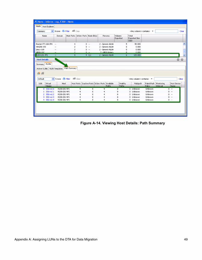
Figure A-14. Viewing Host Details: Path Summary
Appendix A: Assigning LUNs to the DTA for Data Migration 49

Assigning LUNs from an HP EVA 4/6/8000 Series Array
To assign LUNs:
1. Perform zoning as follows:
❖ Connect the Fibre Channel ports of the data migration appliance to a switch where the storage controller ports are also logged.
❖ Using switch management tools, create a zone, DM_Host_EVA.
❖ In this zone, add the WWPN of the data migration appliance Fibre Channel ports and storage controller ports.
❖ Save the zoning information and activate the new zoning configuration.
2. Open the Command View EVA application, as shown in Figure A-15.
Storage Vendor HP
Array Model EVA 4/6/8000 series arrays
LUN Assignment Tool Command View user interface
50 Assigning LUNs from an HP EVA 4/6/8000 Series Array

Figure A-15. Opening Command View EVA
3. In the left pane, double-click the array that you want to manage. This expands the nodes under the selected array.
4. In the left pane, click the Hosts node.
5. Complete the Add a Host information in the right pane as follows (see Figure A-16):
❖ Under Basic Settings in the Name box, type DM-Host.
❖ Under Port World Wide Name, click the WWN of the data migration appliance.
❖ Under Operating System, click Microsoft Windows.
❖ Click the Add host button.
Figure A-16. Adding a Host
6. If you have a multipath configuration, add the second router port to the DM-Host entity as follows (see Figure A-17):
❖ Under the Hosts tree in the left pane, click the DM-Host node.
❖ In the right pane, click the Ports tab.
❖ On the Add a Host Port page, select a WWN, and then click the Add port button.
Appendix A: Assigning LUNs to the DTA for Data Migration 51

Figure A-17. Adding a Second Host Port
7. Present virtual disks as follows (see Figure A-18):
❖ In the left pane, double-click the Virtual Disks node.
❖ Click the LUN that needs to be presented to the data migration appliance for data migration.
❖ In the right pane, click the Presentation tab, and then click the DM-Host.
❖ To accept and save the LUN assignment, click Present Vdisk.
52 Assigning LUNs from an HP EVA 4/6/8000 Series Array
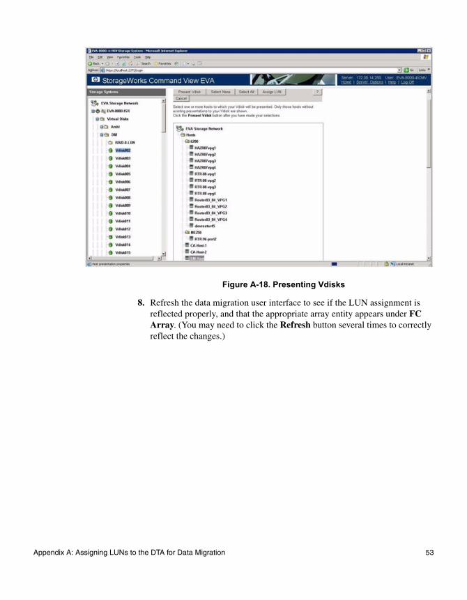
Figure A-18. Presenting Vdisks
8. Refresh the data migration user interface to see if the LUN assignment is reflected properly, and that the appropriate array entity appears under FC Array. (You may need to click the Refresh button several times to correctly reflect the changes.)
Appendix A: Assigning LUNs to the DTA for Data Migration 53
Assigning LUNs from an HDS Array
To assign LUNs:
1. Perform zoning as follows:
❖ Connect the Fibre Channel ports of the data migration appliance to a switch where the storage controller ports are also logged.
❖ Using switch management tools, create a zone, DM_Host_HDS.
❖ In this zone, add the WWPN of the data migration appliance Fibre Channel ports and storage controller ports.
❖ Save the zoning information and activate the new zoning configuration.
2. Open the Storage Navigator Modular application. If you are using the tool for the first time, you may have to discover the array using the IP assigned to the storage controller.
3. On the Tool menu, click Operation Mode > Change, and then change to Management Mode (see Figure A-19).
Storage Vendor HDS
Array Model AMS/WMS series arrays
LUN Assignment Tool Storage Navigator Modular user interface
54 Assigning LUNs from an HDS Array

Figure A-19. Changing to Management Mode
4. Under Array Unit, double-click the name of the array to manage.
The Array System Viewer window opens.
5. In the left pane, click the Logical Status tab.
6. In the left pane, right-click the port of the array that has been zoned with the data migration appliance, and then click Add New Host Group (see Figure A-20).
Appendix A: Assigning LUNs to the DTA for Data Migration 55
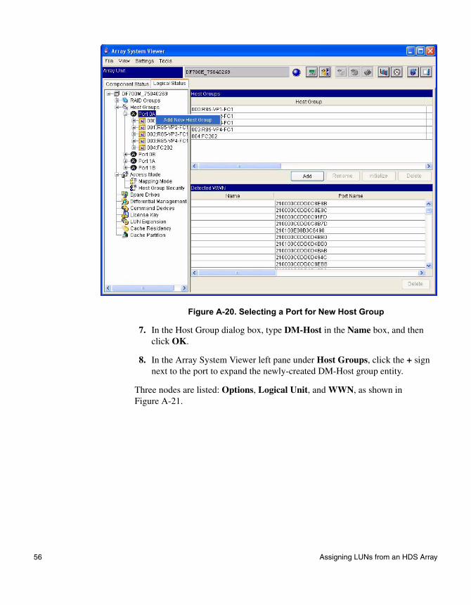
Figure A-20. Selecting a Port for New Host Group
7. In the Host Group dialog box, type DM-Host in the Name box, and then click OK.
8. In the Array System Viewer left pane under Host Groups, click the + sign next to the port to expand the newly-created DM-Host group entity.
Three nodes are listed: Options, Logical Unit, and WWN, as shown in Figure A-21.
56 Assigning LUNs from an HDS Array

Figure A-21. Selecting DM-Host Nodes
9. In the left pane, click the Options node, and then at the bottom of the right pane, click Simple Setting.
10. Complete the Simple Setting dialog box as follows:
❖ Next to Platform, select Windows2003.
❖ Keep the other settings as default.
❖ To save the changes, click OK.
11. In the Array System Viewer dialog box, under the DM-Host group, click the WWN node. Then at the bottom of the right pane, click Modify WWN Information (see Figure A-22).
Appendix A: Assigning LUNs to the DTA for Data Migration 57

Figure A-22. Array System Viewer
12. Complete the Modify WWN Information dialog box as follows:
❖ Under Assignable WWN, click the WWN of the data migration appliance.
❖ Click Add.
❖ To accept and save the WWN information, click OK.
13. Under the DM-Host group, click the Logical Unit node. Then at the bottom of the right pane, click Modify Mapping.
14. Complete the Modify Mapping dialog box as follows (see Figure A-32):
❖ Under H-LUN / Available Logical Units, select an appropriate LUN.
❖ Click the (up arrow) to map the LUN to the DM-Host group.
❖ To accept and save the LUN assignment, click OK.
58 Assigning LUNs from an HDS Array
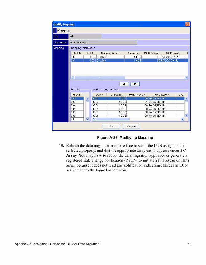
Figure A-23. Modifying Mapping
15. Refresh the data migration user interface to see if the LUN assignment is reflected properly, and that the appropriate array entity appears under FC Array. You may have to reboot the data migration appliance or generate a registered state change notification (RSCN) to initiate a full rescan on HDS array, because it does not send any notification indicating changes in LUN assignment to the logged in initiators.
Appendix A: Assigning LUNs to the DTA for Data Migration 59

Assigning LUNs from an EMC CLARiiON Array
To assign LUNs:
1. Perform zoning as follows:
❖ Connect the Fibre Channel ports of the data migration appliance to a switch where the storage controller ports are also logged.
❖ Using switch management tools, create a zone, DM_Host_EMC.
❖ Add the WWPN of the data migration appliance Fibre Channel ports and storage controller ports in this zone.
❖ Save the zoning information and activate the new zoning configuration.
2. Using Internet Explorer, open the Navisphere utility using the IP assigned to the storage controller.
The Enterprise Storage dialog box opens, as shown in Figure A-24.
Storage Vendor EMC
Array Model CLARiiON® CX/AX series arrays
LUN Assignment Tool Navisphere
60 Assigning LUNs from an EMC CLARiiON Array

Figure A-24. Viewing Enterprise Storage
3. Select the appropriate storage array, right-click the array name, and then click Connectivity Status.
4. Select the WWPN associated with the data migration appliance, and then click Register.
5. Complete the Register Initiator Record dialog box as follows (see Figure A-25):
❖ In the Initiator Type box, click CLARIION Open.
❖ In the Failover Mode box, select 4 (if supported by the array).
❖ Under Host Information, type the values for Host Name, and then type the values for Host Name and IP Address.
❖ Click OK.
Appendix A: Assigning LUNs to the DTA for Data Migration 61
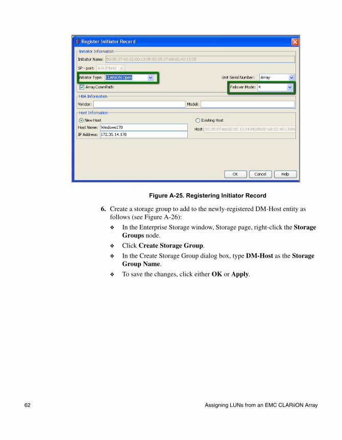
Figure A-25. Registering Initiator Record
6. Create a storage group to add to the newly-registered DM-Host entity as follows (see Figure A-26):
❖ In the Enterprise Storage window, Storage page, right-click the Storage Groups node.
❖ Click Create Storage Group.
❖ In the Create Storage Group dialog box, type DM-Host as the Storage Group Name.
❖ To save the changes, click either OK or Apply.
62 Assigning LUNs from an EMC CLARiiON Array
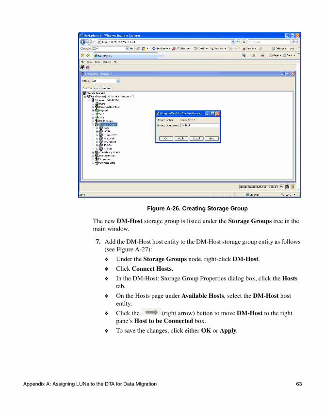
Figure A-26. Creating Storage Group
The new DM-Host storage group is listed under the Storage Groups tree in the main window.
7. Add the DM-Host host entity to the DM-Host storage group entity as follows (see Figure A-27):
❖ Under the Storage Groups node, right-click DM-Host.
❖ Click Connect Hosts.
❖ In the DM-Host: Storage Group Properties dialog box, click the Hosts tab.
❖ On the Hosts page under Available Hosts, select the DM-Host host entity.
❖ Click the (right arrow) button to move DM-Host to the right pane’s Host to be Connected box.
❖ To save the changes, click either OK or Apply.
Appendix A: Assigning LUNs to the DTA for Data Migration 63
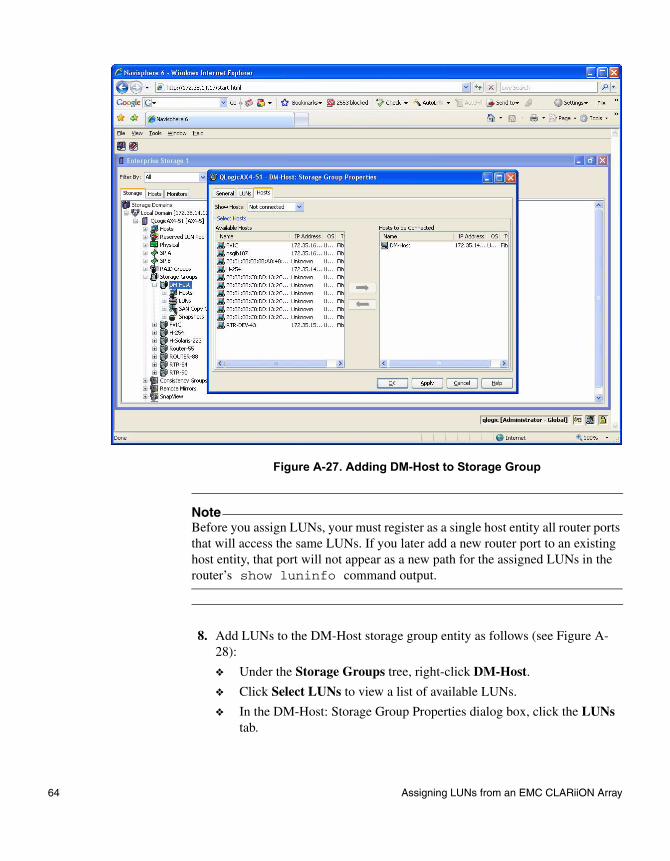
Figure A-27. Adding DM-Host to Storage Group
8. Add LUNs to the DM-Host storage group entity as follows (see Figure A-28):
❖ Under the Storage Groups tree, right-click DM-Host.
❖ Click Select LUNs to view a list of available LUNs.
❖ In the DM-Host: Storage Group Properties dialog box, click the LUNs tab.
NoteBefore you assign LUNs, your must register as a single host entity all router ports that will access the same LUNs. If you later add a new router port to an existing host entity, that port will not appear as a new path for the assigned LUNs in the router’s show luninfo command output.
64 Assigning LUNs from an EMC CLARiiON Array

❖ On the LUNs page, select All on the Show LUNs list to view all LUNs that have been assigned to the host and will be part of the data migration jobs.
❖ Under Available LUNs, select the check box next to each LUN to be assigned for data migration jobs (as determined during the planning phase of the data migration activity).
Figure A-28. Adding LUNs to DM-Host
9. Refresh the data migration user interface to see if the LUN assignment is reflected properly, and that the appropriate array entity appears under FC Array. (You may need to click the Refresh button several times to correctly update the display.)
Appendix A: Assigning LUNs to the DTA for Data Migration 65
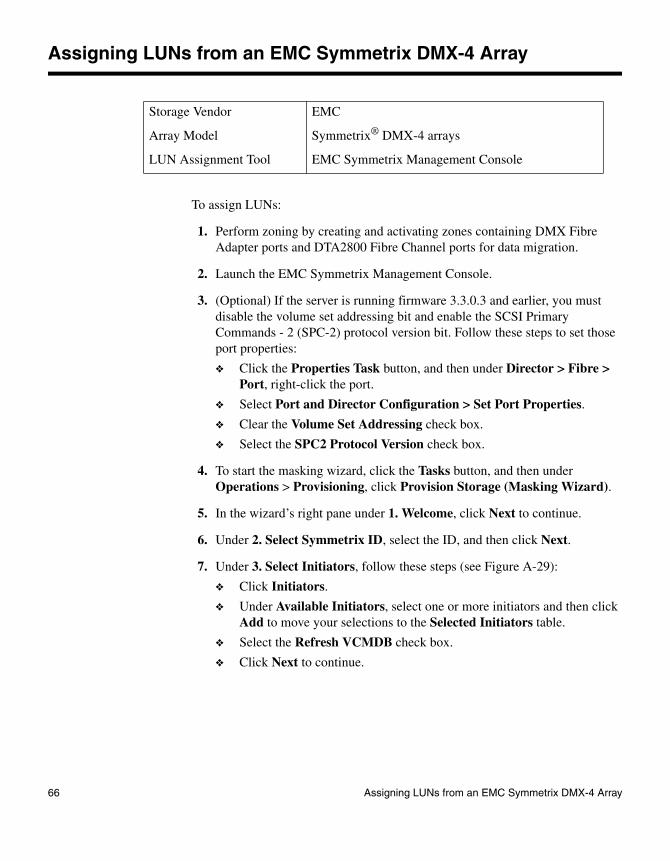
Assigning LUNs from an EMC Symmetrix DMX-4 Array
To assign LUNs:
1. Perform zoning by creating and activating zones containing DMX Fibre Adapter ports and DTA2800 Fibre Channel ports for data migration.
2. Launch the EMC Symmetrix Management Console.
3. (Optional) If the server is running firmware 3.3.0.3 and earlier, you must disable the volume set addressing bit and enable the SCSI Primary Commands - 2 (SPC-2) protocol version bit. Follow these steps to set those port properties:
❖ Click the Properties Task button, and then under Director > Fibre > Port, right-click the port.
❖ Select Port and Director Configuration > Set Port Properties.
❖ Clear the Volume Set Addressing check box.
❖ Select the SPC2 Protocol Version check box.
4. To start the masking wizard, click the Tasks button, and then under Operations > Provisioning, click Provision Storage (Masking Wizard).
5. In the wizard’s right pane under 1. Welcome, click Next to continue.
6. Under 2. Select Symmetrix ID, select the ID, and then click Next.
7. Under 3. Select Initiators, follow these steps (see Figure A-29):
❖ Click Initiators.
❖ Under Available Initiators, select one or more initiators and then click Add to move your selections to the Selected Initiators table.
❖ Select the Refresh VCMDB check box.
❖ Click Next to continue.
Storage Vendor EMC
Array Model Symmetrix® DMX-4 arrays
LUN Assignment Tool EMC Symmetrix Management Console
66 Assigning LUNs from an EMC Symmetrix DMX-4 Array
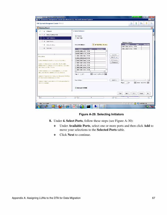
Figure A-29. Selecting Initiators
8. Under 4. Select Ports, follow these steps (see Figure A-30):
❖ Under Available Ports, select one or more ports and then click Add to move your selections to the Selected Ports table.
❖ Click Next to continue.
Appendix A: Assigning LUNs to the DTA for Data Migration 67

Figure A-30. Selecting Ports
9. In the right pane under 5. Select Devices, follow these steps (see Figure A-31):
❖ For Group Type, select Ungrouped.
❖ Under Available Devices, select one or more devices, and then click Add to move your selections to the Selected Devices table.
❖ Select the Map selected devices to all ports check box.
❖ Click Next to continue.
68 Assigning LUNs from an EMC Symmetrix DMX-4 Array

Figure A-31. Selecting Devices
10. In the right pane under 6. Summary, review your masking selections and then either click Back to modify a previous step, click Next to continue, or click Finish to close the masking wizard and return to the Tasks page of the EMC Symmetrix Management console.
A message box informs you that the Symmetrix device masking session completed successfully.
Appendix A: Assigning LUNs to the DTA for Data Migration 69

Assigning LUNs from an IBM DS4K/DS5K/LSI Array
To assign LUNs:
1. Perform zoning as follows:
❖ Connect the Fibre Channel ports of the data migration appliance to a switch where the storage controller ports are also logged.
❖ Using switch management tools, create a zone, DM_Host_IBM.
❖ In this zone, add the WWPN of the data migration appliance Fibre Channel ports and storage controller ports.
❖ Save the zoning information and activate the new zoning configuration.
2. Open the Storage Manager Client configuration utility, and then select the array to manage.
3. On the Subsystem Management window, in the left pane, click the Mappings View tab.
4. In the left pane, right-click Default Group, point to Define, and then click Host. (see Figure A-32).
Figure A-32. Selecting Host to Define
5. Complete the Define Host wizard as follows (see Figure A-33):
Storage Vendor IBM
Array Model IBM DS4000/Engineo series arrays
LUN Assignment Tool Storage Manager Client 1e
70 Assigning LUNs from an IBM DS4K/DS5K/LSI Array

Figure A-33. Defining the Host
❖ Under Specify name of host, type DM-Host as the name for the data migration appliance.
❖ In the Known HBA host port identifiers box, click the WWPN of the data migration appliance.
❖ Click Add to move the selected WWPN to the Selected HBA host port identifiers/aliases box.
❖ Click Edit, and then in the Edit Identifier/Alias dialog box, type an alias for the WWPN. Click OK to close the dialog box.
❖ Click Next.
❖ In the Specify Host Type window (see Figure A-34) under Host type (operating system), click Windows 2000/Server 2003 Non-Clustered.
Appendix A: Assigning LUNs to the DTA for Data Migration 71
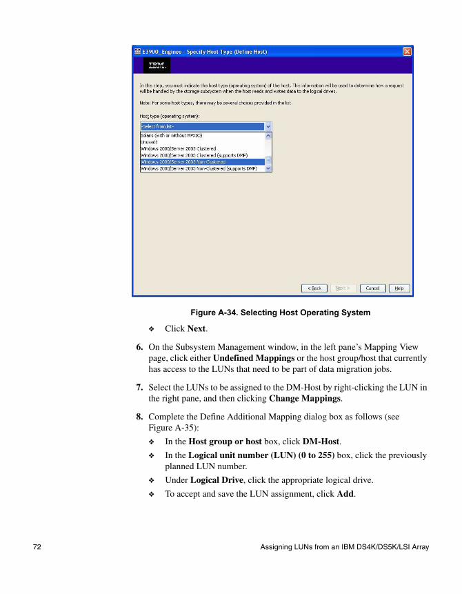
Figure A-34. Selecting Host Operating System
❖ Click Next.
6. On the Subsystem Management window, in the left pane’s Mapping View page, click either Undefined Mappings or the host group/host that currently has access to the LUNs that need to be part of data migration jobs.
7. Select the LUNs to be assigned to the DM-Host by right-clicking the LUN in the right pane, and then clicking Change Mappings.
8. Complete the Define Additional Mapping dialog box as follows (see Figure A-35):
❖ In the Host group or host box, click DM-Host.
❖ In the Logical unit number (LUN) (0 to 255) box, click the previously planned LUN number.
❖ Under Logical Drive, click the appropriate logical drive.
❖ To accept and save the LUN assignment, click Add.
72 Assigning LUNs from an IBM DS4K/DS5K/LSI Array
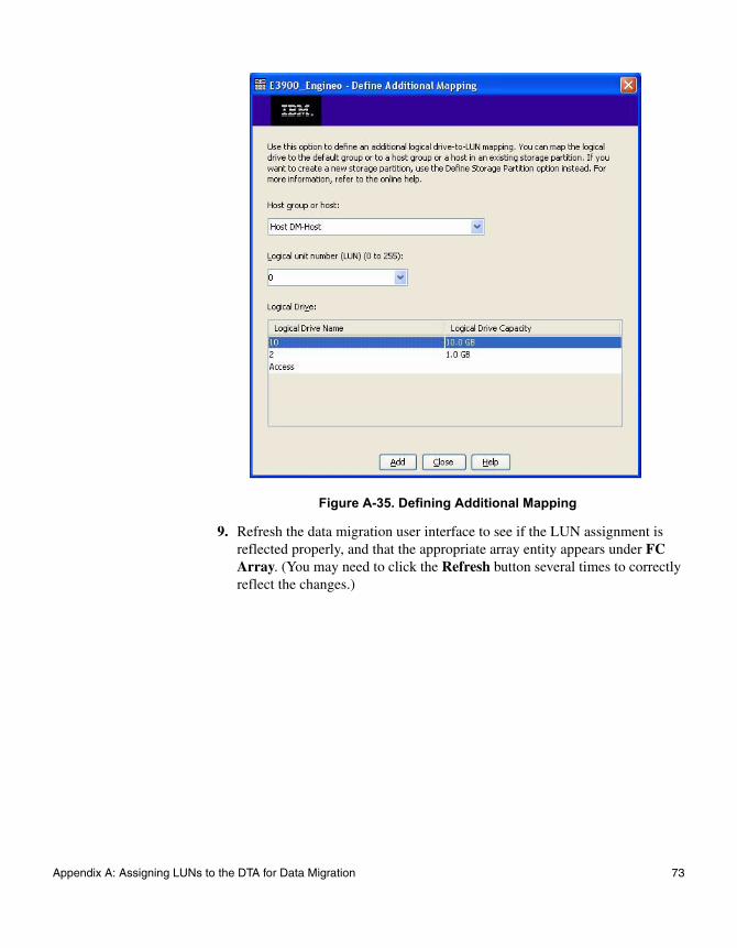
Figure A-35. Defining Additional Mapping
9. Refresh the data migration user interface to see if the LUN assignment is reflected properly, and that the appropriate array entity appears under FC Array. (You may need to click the Refresh button several times to correctly reflect the changes.)
Appendix A: Assigning LUNs to the DTA for Data Migration 73
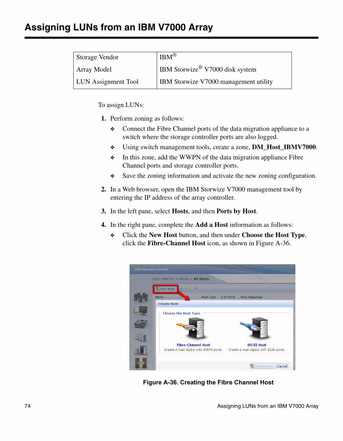
Assigning LUNs from an IBM V7000 Array
To assign LUNs:
1. Perform zoning as follows:
❖ Connect the Fibre Channel ports of the data migration appliance to a switch where the storage controller ports are also logged.
❖ Using switch management tools, create a zone, DM_Host_IBMV7000.
❖ In this zone, add the WWPN of the data migration appliance Fibre Channel ports and storage controller ports.
❖ Save the zoning information and activate the new zoning configuration.
2. In a Web browser, open the IBM Storwize V7000 management tool by entering the IP address of the array controller.
3. In the left pane, select Hosts, and then Ports by Host.
4. In the right pane, complete the Add a Host information as follows:
❖ Click the New Host button, and then under Choose the Host Type, click the Fibre-Channel Host icon, as shown in Figure A-36.
Figure A-36. Creating the Fibre Channel Host
Storage Vendor IBM®
Array Model IBM Storwize® V7000 disk system
LUN Assignment Tool IBM Storwize V7000 management utility
74 Assigning LUNs from an IBM V7000 Array

❖ (Optional) Type the host name in the Host Name box.
❖ Select the WWPN from the Fibre-Channel Ports list, and then click the Add Port to List button.
❖ Create one host for each virtual port group (VPG), and then assign a host name to each VPG.
5. Complete the Create Host dialog box as follows (see Figure A-37):
❖ (Optional) In the Host Name (optional) box, type a user-defined name for the new host.
❖ Under Fibre-Channel Ports, select the WWPN associated with the host, and then click the Add Port to List button.
❖ Under Advanced Settings, click Generic (default) as the Host Type.
❖ Click the Create Host button.
Figure A-37. Creating a Host
NoteIf the zoned data migration appliance port is not visible as the default, manually enter the WWPN. Create a separate initiator group for each VPG. If more than one VPG is enabled and used, create a separate initiator group for each.
Appendix A: Assigning LUNs to the DTA for Data Migration 75

The newly created host is now listed with the registered WWPNs under Host Filter, as shown in Figure A-38.
Figure A-38. Viewing the New Host
6. Present volumes to the router as follows:
❖ In the left pane, select Volumes, point to All Volumes, and then click the volume to be presented.
❖ In the Volumes by Pool window under Status, click Map to Host.
❖ On the small Modify Mappings dialog box, select the host from the list, and then click Next.
The large Modify Mappings dialog box’s right pane shows the volume with the SCSI ID, name, and the user identifier (UID).
❖ In the right pane, change the SCSI ID of the volume by right-clicking the newly added volume, and clicking Edit SCSI ID.
❖ To complete the presentation wizard, click OK.
7. To confirm the mappings to the host:
❖ In the left pane, point to Volumes, and then click Volume by Hosts.
❖ Under Host Filter, select the host.
❖ Ensure that all volumes are shown with the status Online, as shown in Figure A-39.
76 Assigning LUNs from an IBM V7000 Array

Figure A-39. Confirming Mappings
Appendix A: Assigning LUNs to the DTA for Data Migration 77
Assigning LUNs from a NetApp FAS2040 System Using FilerView
To assign LUNs:
1. Perform zoning as follows:
❖ Connect the Fibre Channel ports of the data migration appliance to a switch where the storage controller ports are also logged.
❖ Using switch management tools, create a zone, DM_Host_Netapp.
❖ In this zone, add the WWPN of the data migration appliance Fibre Channel ports and storage controller ports.
❖ Save the zoning information and activate the new zoning configuration.
2. In a Web browser, open the NetApp FilerView tool by entering the IP address of the array controller.
3. Create an initiator group as follows:
❖ In the left pane under LUNs, select Initiator Groups, and then click Add.
❖ Complete the Add Initiator Group area in the right pane (see Figure A-40).
Storage Vendor NetApp®
Array Model FAS2040 system
LUN Assignment Tool FilerView® CLI-based management tool
78 Assigning LUNs from a NetApp FAS2040 System Using FilerView

Figure A-40. Adding Initiator Group
❖ In the Group Name box, type DM_host.
❖ For host Type, select FCP.
❖ For Operating System, select Microsoft Windows.
❖ In the Initiators box, select the WWPN of the data migration appliance Fibre Channel port.
❖ At the bottom of the right pane, click Add.
4. Present the LUN as follows:
❖ In the left pane under LUNs, click Manage to open the Manage LUNs area in the right pane (see Figure A-41).
NoteIf the zoned data migration appliance port is not visible in the Initiators box, manually type the WWPN. Remove all other WWPNs (if any) that do not belong to the data migration appliance. If more than one VPG is enabled and used, create a separate initiator group for each virtual port group.
Appendix A: Assigning LUNs to the DTA for Data Migration 79
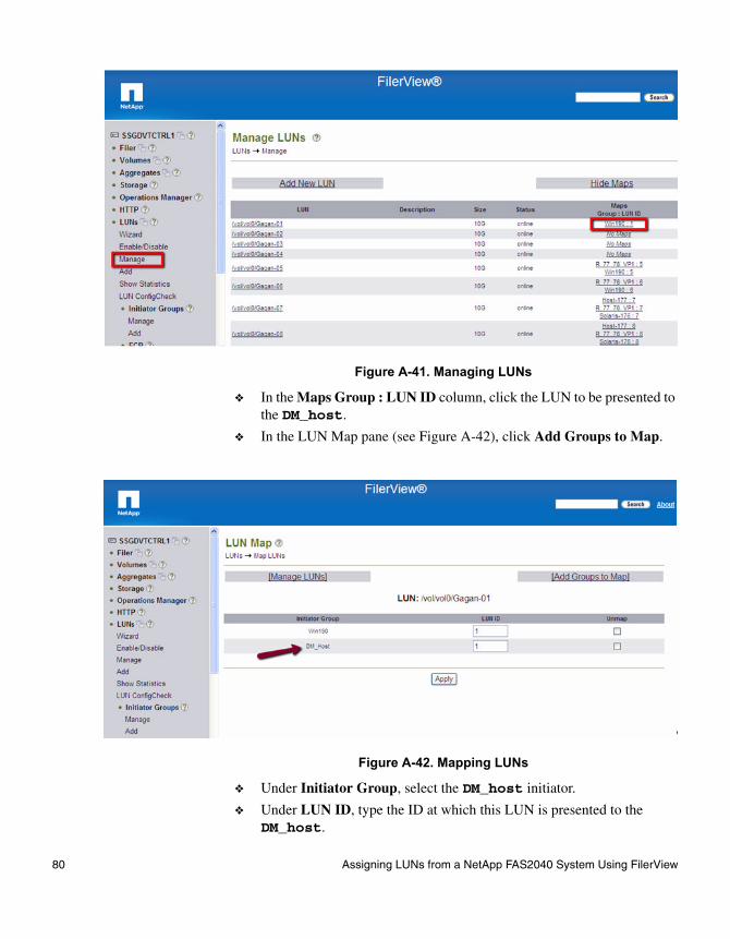
Figure A-41. Managing LUNs
❖ In the Maps Group : LUN ID column, click the LUN to be presented to the DM_host.
❖ In the LUN Map pane (see Figure A-42), click Add Groups to Map.
Figure A-42. Mapping LUNs
❖ Under Initiator Group, select the DM_host initiator.
❖ Under LUN ID, type the ID at which this LUN is presented to the DM_host.
80 Assigning LUNs from a NetApp FAS2040 System Using FilerView
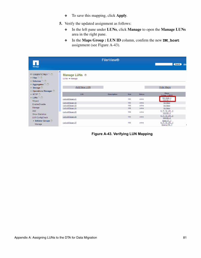
❖ To save this mapping, click Apply.
5. Verify the updated assignment as follows:
❖ In the left pane under LUNs, click Manage to open the Manage LUNs area in the right pane.
❖ In the Maps Group : LUN ID column, confirm the new DM_host assignment (see Figure A-43).
Figure A-43. Verifying LUN Mapping
Appendix A: Assigning LUNs to the DTA for Data Migration 81

Assigning LUNs from a NetApp FAS2040 System Using NetApp System Manager
To assign LUNs:
1. Perform zoning as follows:
❖ Connect the Fibre Channel ports of the data migration appliance to a switch where the storage controller ports are also logged.
❖ Using switch management tools, create a zone, DM_Host_Netapp.
❖ In this zone, add the WWPN of the data migration appliance Fibre Channel ports and storage controller ports.
❖ Save the zoning information and activate the new zoning configuration.
2. Start NetApp System Manager.
3. In the left pane, expand the tree, and then under the Storage node, click LUNs.
4. In the right pane, click the Initiator Groups tab, and then under Initiator Groups, click the Add button.
5. Complete the Add Initiator Group dialog box (see Figure A-44) as follows:
❖ In the Group Name box, type a user-defined name (this example uses DM-Appliance).
❖ For Group Type, select FCP.
❖ For Operating System, select Windows.
❖ Select the ALUA (Asymmetric Logical Unit Access) features enabled check box.
❖ Click Add.
Storage Vendor NetApp®
Array Model FAS2040 system
LUN Assignment Tool NetApp System Manager
82 Assigning LUNs from a NetApp FAS2040 System Using NetApp System Manager

Figure A-44. Adding an Initiator Group
6. On the Initiator Groups page under Initiator IDs, click the Add button.
7. Complete the Add Initiator ID dialog box (see Figure A-45) as follows:
❖ For Group Type, select FCP.
❖ For Group Name, select the user-defined name that you specified in Step 5 (DM-Appliance, for example).
❖ In the Initiator Name box, type the WWPN of the appliance.
❖ Click Add.
Figure A-45. Adding an Initiator ID
8. Repeat Step 7 to add the WWPN of each virtual port.
9. Present the LUN as follows:
NoteIf more than one virtual port is enabled and used, create an initiator group for each virtual port group.
Appendix A: Assigning LUNs to the DTA for Data Migration 83

❖ In the left pane, expand the tree, and then under the Storage node, click LUNs.
❖ In the right pane, click the LUN Management tab.
❖ On the LUN Management page, right-click the volume that you want to present to the data migration appliance, and then click Properties.
❖ Complete the LUN ‘Volume xx’ Properties page (see Figure A-46) as follows.
❖ Click the Initiators tab.
❖ Under Known initiator hosts, select the initiator group name that you specified in Step 5.
❖ Click the right-arrow button to move the selected initiator group to the Hosts to connect box on the right.
❖ Click Apply.
Figure A-46. Selecting Hosts to Connect
84 Assigning LUNs from a NetApp FAS2040 System Using NetApp System Manager

Assigning LUNs from a NetApp FAS6280 System Using Data ONTAP Element Manager
To assign LUNs:
1. Perform zoning as follows:
❖ Connect the Fibre Channel ports of the data migration appliance to a switch where the storage controller ports are also logged.
❖ Using switch management tools, create a zone, DM_Host_Netapp.
❖ In this zone, add the WWPN of the data migration appliance Fibre Channel ports and storage controller ports.
❖ Save the zoning information and activate the new zoning configuration.
2. Sart Data ONTAP Element Manager.
3. In the left pane, expand the tree LUN, and then under the LUN, click igroup.
4. In the right pane, click the Create New Entry Button.
5. Complete the igroup Table (see Figure A-47) as follows:
❖ In the Vserver Name box, select the Vserver name.
❖ In the Group Name box, type a user-defined name (this example uses DM-Appliance).
❖ In the Protocol box, select mixed if using FCP and iSCSI.
❖ In the FCP and iSCSI box, leave blank.
❖ In the OS Type, select windows.
❖ In the Portset Binding Igroup, type portset name if binding this igroup to a portset otherwise leave blank.
❖ In the Initiators box, type all WWPN of the data migration appliance virtual port group.
Storage Vendor NetApp®
Array Model FAS6280 system
LUN Assignment Tool Data ONTAP Element Manager
Appendix A: Assigning LUNs to the DTA for Data Migration 85

Figure A-47. Adding an Initiator Group
NoteNote: If more than one virtual port group is enabled and used, create an initiator group for each virtual port group.
6. Present the LUN as follows:
❖ In the left pane, expand the tree LUN, and then under the LUN, click manage.
❖ In the right pane, click on LUN name that needs to be presented to the data migration appliance for data migration.
❖ In the LUN table, click map.
86 Assigning LUNs from a NetApp FAS6280 System Using Data ONTAP Element Manager

Figure A-48. LUN table
7. On LUN map table, in the Initiator Group Name box, type DM-Appliance.
8. In the LUN ID box, type the previously planned LUN number for the LUN.
9. Click map.
Figure A-49. Selecting Hosts to Connect
Appendix A: Assigning LUNs to the DTA for Data Migration 87

Assigning LUNs from a NetApp E-Series System Using SANtricity Storage Manager
To assign LUNs:
1. Perform zoning as follows:
❖ Connect the Fibre Channel ports of the data migration appliance to a switch where the storage controller ports are also logged.
❖ Using switch management tools, create a zone, DM_Host_Netapp.
❖ In this zone, add the WWPN of the data migration appliance Fibre Channel ports and storage controller ports.
❖ Save the zoning information and activate the new zoning configuration.
2. Start SANtricity ES Storage Manager Client.
3. Under Setup tab, click on Manage a Storage Array
4. In Select Storage Array dialog box, select Array that is being used for migration and click OK.
5. Under SANtricity ES (Array Management), select Setup tab.
6. Under Setup tab, click on Manually Define Hosts.
7. In Host name box, type a user-defined name (this example uses DM-Appliance).
8. Select Yes to use Storage partitions on this storage array and click Next.
Storage Vendor NetApp®
Array Model E-Series System
LUN Assignment Tool SANtricity Storage Manager
88 Assigning LUNs from a NetApp E-Series System Using SANtricity Storage Manager

Figure A-50. Specify Host Name (Define Host)
9. In the Choose a host interface type, choose FC.
10. If Data migration appliance to storage zoning is complete, select appliance WWPN in the Add by selecting a known unassociated host port identifier box. It not seen, type appliance WWPN manually under Add by creating a new host port identifier.
11. In Alias (30 characters maximum) box, type user-defined Alias (this example uses DTA-Blade1-FC1-VPG1)
12. Select Add
Appendix A: Assigning LUNs to the DTA for Data Migration 89
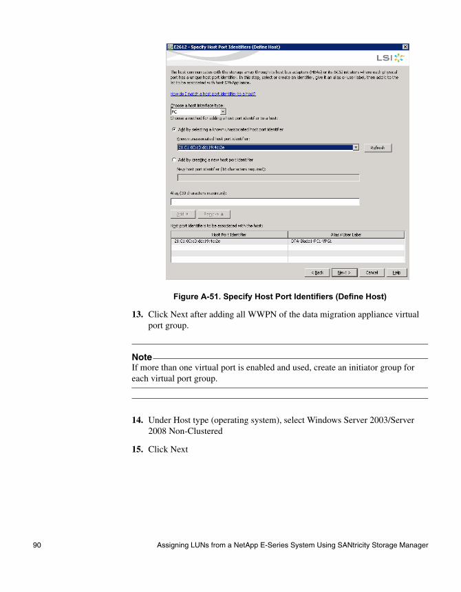
Figure A-51. Specify Host Port Identifiers (Define Host)
13. Click Next after adding all WWPN of the data migration appliance virtual port group.
14. Under Host type (operating system), select Windows Server 2003/Server 2008 Non-Clustered
15. Click Next
NoteIf more than one virtual port is enabled and used, create an initiator group for each virtual port group.
90 Assigning LUNs from a NetApp E-Series System Using SANtricity Storage Manager

Figure A-52. Specify Host Type (Define Host)
16. In next windows, select No - this host will NOT share access to the same volumes with other hosts.
17. Click Next
Figure A-53. Host Group Question (Define Host)
18. Select Finish in the Preview Window to create host.
19. Present the LUNs as follows:
❖ Start SANtricity ES Storage Manager Client.
❖ Under Setup tab, click on Manage a Storage Array
❖ In Select Storage Array dialog box, select Array that is being used for migration and click OK.
❖ Under SANtricity ES (Array Management), select Setup tab.
❖ Under Setup tab, click on Map Volumes
Appendix A: Assigning LUNs to the DTA for Data Migration 91
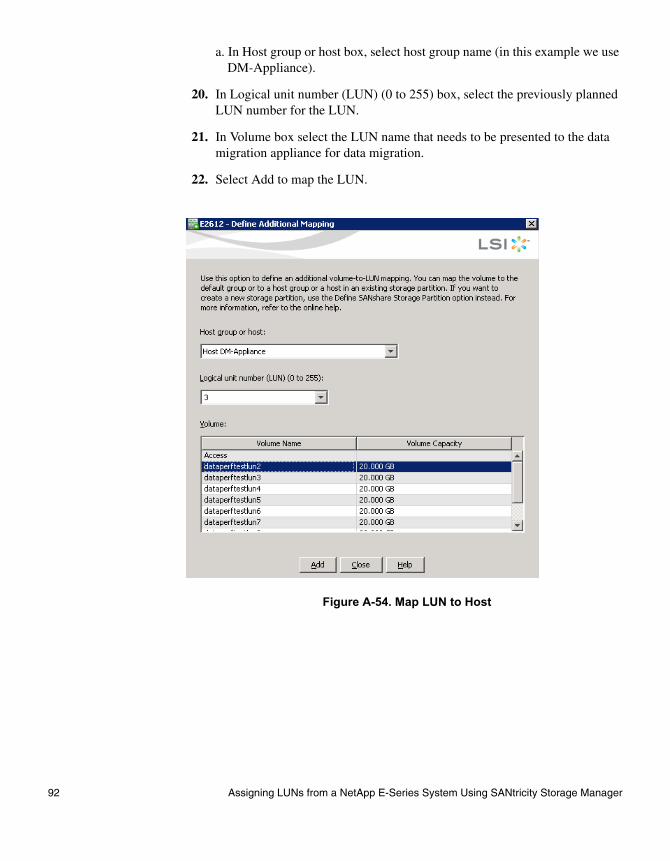
a. In Host group or host box, select host group name (in this example we use DM-Appliance).
20. In Logical unit number (LUN) (0 to 255) box, select the previously planned LUN number for the LUN.
21. In Volume box select the LUN name that needs to be presented to the data migration appliance for data migration.
22. Select Add to map the LUN.
Figure A-54. Map LUN to Host
92 Assigning LUNs from a NetApp E-Series System Using SANtricity Storage Manager
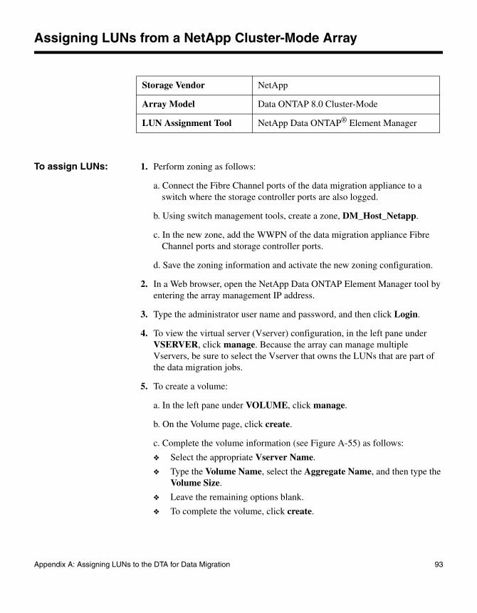
Assigning LUNs from a NetApp Cluster-Mode Array
To assign LUNs: 1. Perform zoning as follows:
a. Connect the Fibre Channel ports of the data migration appliance to a switch where the storage controller ports are also logged.
b. Using switch management tools, create a zone, DM_Host_Netapp.
c. In the new zone, add the WWPN of the data migration appliance Fibre Channel ports and storage controller ports.
d. Save the zoning information and activate the new zoning configuration.
2. In a Web browser, open the NetApp Data ONTAP Element Manager tool by entering the array management IP address.
3. Type the administrator user name and password, and then click Login.
4. To view the virtual server (Vserver) configuration, in the left pane under VSERVER, click manage. Because the array can manage multiple Vservers, be sure to select the Vserver that owns the LUNs that are part of the data migration jobs.
5. To create a volume:
a. In the left pane under VOLUME, click manage.
b. On the Volume page, click create.
c. Complete the volume information (see Figure A-55) as follows:
❖ Select the appropriate Vserver Name.
❖ Type the Volume Name, select the Aggregate Name, and then type the Volume Size.
❖ Leave the remaining options blank.
❖ To complete the volume, click create.
Storage Vendor NetApp
Array Model Data ONTAP 8.0 Cluster-Mode
LUN Assignment Tool NetApp Data ONTAP® Element Manager
Appendix A: Assigning LUNs to the DTA for Data Migration 93
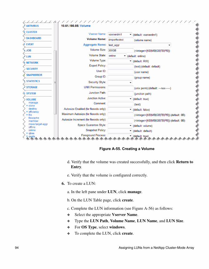
Figure A-55. Creating a Volume
d. Verify that the volume was created successfully, and then click Return to Entry.
e. Verify that the volume is configured correctly.
6. To create a LUN:
a. In the left pane under LUN, click manage.
b. On the LUN Table page, click create.
c. Complete the LUN information (see Figure A-56) as follows:
❖ Select the appropriate Vserver Name.
❖ Type the LUN Path, Volume Name, LUN Name, and LUN Size.
❖ For OS Type, select windows.
❖ To complete the LUN, click create.
94 Assigning LUNs from a NetApp Cluster-Mode Array

Figure A-56. Creating a LUN
d. Verify that the LUN was created successfully, and then click Return to Table.
e. Verify that the LUN is configured correctly.
7. As needed, repeat the preceding step to create additional LUNs.
8. To create an initiator group (igroup):
a. In the left pane under LUN, click igroup.
b. On the Igroup Table page, click create.
c. Complete the igroup information (see Figure A-57) as follows:
❖ Select the appropriate Vserver Name.
❖ Type the Igroup Name.
❖ For Protocol, select mixed.
❖ For FCP, select true or leave this field blank. (Because FCP is supported for this igroup, leaving it blank does not make a difference because the protocol is defined as “mixed.”)
❖ For the OS Type, select windows.
Appendix A: Assigning LUNs to the DTA for Data Migration 95

❖ For Initiators, type all host initiators that are applicable; use a comma to separate the entries.
❖ To complete the igroup, click create.
Figure A-57. Creating an Initiator Group
d. Verify that the igroup is configured correctly.
9. To map a LUN to a host igroup:
a. In the left pane under LUN, click manage.
b. On the LUN Table page, select a LUN, and then click map.
c. Complete the LUN map information (see Figure A-58) as follows:
❖ Select the appropriate Vserver Name.
❖ Type the LUN Path, Initiator Group Name, and LUN ID in the appropriate boxes.
❖ Click map.
96 Assigning LUNs from a NetApp Cluster-Mode Array
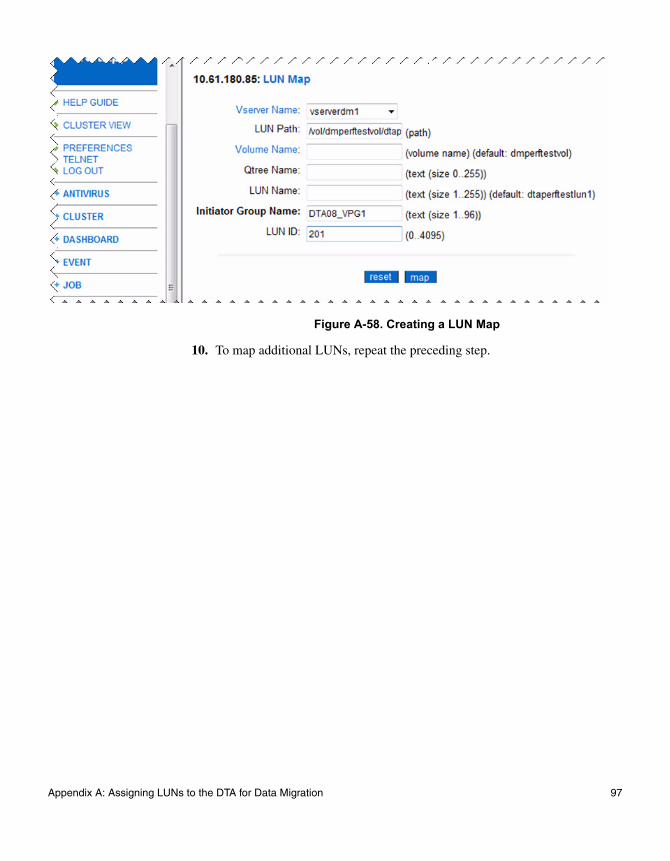
Figure A-58. Creating a LUN Map
10. To map additional LUNs, repeat the preceding step.
Appendix A: Assigning LUNs to the DTA for Data Migration 97

Assigning LUNs from a NetApp E-Series Array
To assign LUNs: 1. Perform zoning as follows:
a. Connect the Fibre Channel ports of the data migration appliance to a switch where the storage controller ports are also logged.
b. Using switch management tools, create a zone, DM_Host_netapp.
c. In this zone, add the WWPN of the data migration appliance Fibre Channel ports and storage controller ports.
d. Save the zoning information and activate the new zoning configuration.
2. Open the SANtricity ES (Enterprise Management) tool.
3. Click the Setup tab, and then under Array Management, click Manage a Storage Array.
4. On the Select Storage Array window, click OK.
5. Create a logical volume as follows:
a. On the <Unnamed> array configuration window, click the Logical tab.
b. In the left pane, right-click the Free Capacity icon, and then click Create Volume.
c. On the Introduction (Create Volume) wizard window, click Next.
d. Complete the Specify Capacity/Name (Create Volume) wizard window (see Figure A-59) as follows:
❖ Specify the New volume capacity and Volume name.
❖ Click the Customize settings option.
❖ Click Next.
Storage Vendor NetApp
Array Model NetApp E-Series (formerly LSI)
LUN Assignment Tool
SANtricity® ES
98 Assigning LUNs from a NetApp E-Series Array

Figure A-59. Creating a Volume: Volume Parameters
e. Complete the Customize Advanced Volume Parameters (Create Volume) wizard window (see Figure A-60) as follows:
❖ Under Volume I/O characteristics type, click File system (typical).
❖ Under Preferred controller ownership, click Slot A.
❖ Click Next.
Appendix A: Assigning LUNs to the DTA for Data Migration 99
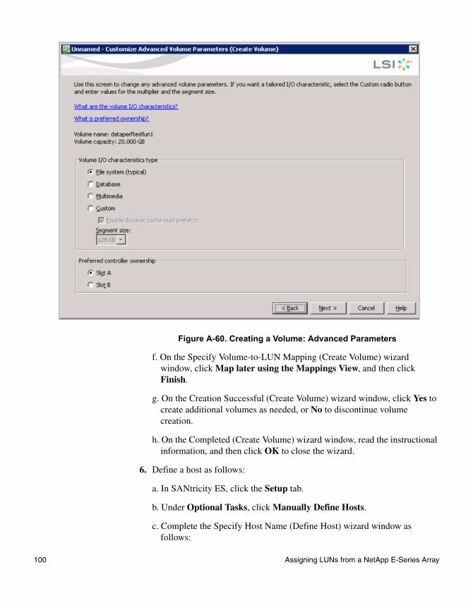
Figure A-60. Creating a Volume: Advanced Parameters
f. On the Specify Volume-to-LUN Mapping (Create Volume) wizard window, click Map later using the Mappings View, and then click Finish.
g. On the Creation Successful (Create Volume) wizard window, click Yes to create additional volumes as needed, or No to discontinue volume creation.
h. On the Completed (Create Volume) wizard window, read the instructional information, and then click OK to close the wizard.
6. Define a host as follows:
a. In SANtricity ES, click the Setup tab.
b. Under Optional Tasks, click Manually Define Hosts.
c. Complete the Specify Host Name (Define Host) wizard window as follows:
100 Assigning LUNs from a NetApp E-Series Array
❖ Type the Host name.
❖ Click Yes in response to the question, Do you plan to use storage partitions on this storage array?
❖ Click Next.
d. Complete the Specify Host Port Identifiers (Define Host) wizard window (see Figure A-61) as follows:
❖ Under Choose a host interface type, select FC.
❖ Select the Add by selecting a known unassociated host port identifier option.
❖ Under Known unassociated host port identifier, select the WWPN associated with the router port.
❖ Under Alias (30 characters maximum), type an alias name, and then click Add.
❖ Continue adding aliases for all host ports.
❖ Click Next.
Appendix A: Assigning LUNs to the DTA for Data Migration 101
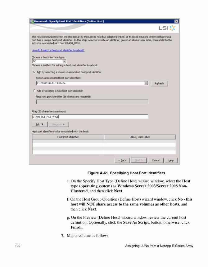
Figure A-61. Specifying Host Port Identifiers
e. On the Specify Host Type (Define Host) wizard window, select the Host type (operating system) as Windows Server 2003/Server 2008 Non-Clustered, and then click Next.
f. On the Host Group Question (Define Host) wizard window, click No - this host will NOT share access to the same volumes as other hosts, and then click Next.
g. On the Preview (Define Host) wizard window, review the current host definition. Optionally, click the Save As Script, button; otherwise, click Finish.
7. Map a volume as follows:
102 Assigning LUNs from a NetApp E-Series Array

a. In SANtricity ES, click the Setup tab.
b. Under Storage Array Configuration, click Map Volumes.
c. Complete the Define Additional Mapping dialog box (see Figure A-62) as follows:
❖ Select the Host group or host.
❖ Select the Logical unit number (LUN).
❖ Click the Volume Name.
❖ Click Add.
Figure A-62. Mapping a Volume
d. As needed, repeat the preceding step for additional LUNs.
e. When all LUNs are mapped, click Close.
Appendix A: Assigning LUNs to the DTA for Data Migration 103

Assigning LUNs from a NetApp FAS iSCSI Array
Before you assign LUNs from a NetApp FAS iSCSI array, connect and configure the DTA2800 to an iSCSI switch as follows:
1. Ensure that either the 1GbE or 10GbE port of the DTA2800 is connected to the iSCSI switch.
2. Ensure that the network domain settings of the 1GbE or 10GbE port matches the domain setting of the NetApp FAS array.
To assign LUNs from a 7-Mode array:
1. Open NetApp OnCommand System Manager.
2. From the Home tab, double-click the appropriate storage system.
3. In the navigation pane, click Storage > LUNs.
4. In the LUN Management tab, click Create.
5. Type or select information as prompted by the wizard, and click Next to proceed.
6. Create an iSCSI Initiator Group as follows:
a. In the Initiators Mapping section, click Add Initiator Group.
Storage Vendor NetApp
Array Model All FAS Series systems
LUN Assignment Tool NetApp OnCommand System Manager
104 Assigning LUNs from a NetApp FAS iSCSI Array

b. In the General tab, specify the initiator group name, operating system, and select iSCSI as the supported protocol for the group.
c. In the Initiators tab, click Add and type the initiator’s iSCSI qualified name (IQN).
Appendix A: Assigning LUNs to the DTA for Data Migration 105

d. Click Create.
7. Map the LUNs to the initiator hosts by selecting from the initiator groups and click Next.
8. Review the summary and make necessary changes if needed by using the Back button to go back.
9. Confirm the details and click Finish to complete the wizard.
To assign LUNs from a clustered Data ONTAP Vserver:
1. Open NetApp OnCommand System Manager.
2. From the Home tab, double-click the appropriate storage system.
3. Expand the Vservers hierarchy in the left navigation pane.
106 Assigning LUNs from a NetApp FAS iSCSI Array
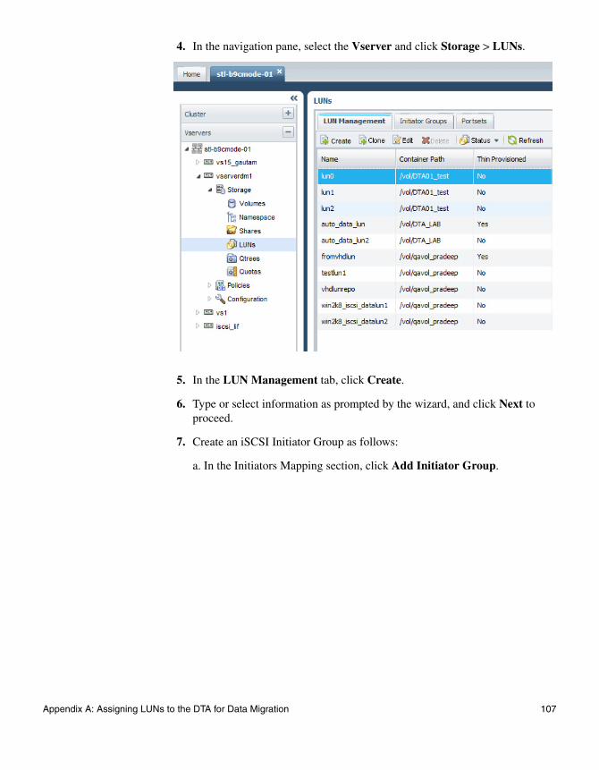
4. In the navigation pane, select the Vserver and click Storage > LUNs.
5. In the LUN Management tab, click Create.
6. Type or select information as prompted by the wizard, and click Next to proceed.
7. Create an iSCSI Initiator Group as follows:
a. In the Initiators Mapping section, click Add Initiator Group.
Appendix A: Assigning LUNs to the DTA for Data Migration 107

b. In the General tab, specify the initiator group name, operating system, and select iSCSI as the supported protocol for the group.
c. In the Initiators tab, click Add and type the initiator’s iSCSI qualified name (IQN).
d. Click Create.
8. Map the LUNs to the initiator hosts by selecting from the initiator groups and click Next.
9. Review the summary and make necessary changes if needed by using the Back button to go back.
10. Confirm the details and click Finish to complete the wizard.
108 Assigning LUNs from a NetApp FAS iSCSI Array

Assigning LUNs from a Xiotech Emprise 5000 Array
To assign LUNs:
1. Perform zoning as follows:
❖ Connect the Fibre Channel ports of the data migration appliance to a switch where the storage controller ports are also logged.
❖ Using switch management tools, create a zone, DM_Host_Emprise5000.
❖ In this zone, add the WWPN of the data migration appliance Fibre Channel ports and storage controller ports.
❖ Save the zoning information and activate the new zoning configuration.
2. In a Web browser, open the Emprise 5000 Management tool by entering the array management IP address.
3. Click Login, and then type the login user name and password.
4. On the At-A-Glance Status Summary window, click Hosts, and then select create host.
5. Complete the Host Configuration window (see Figure A-63) as follows:
❖ In the Name box, type a user-defined host name.
❖ Under Operating System Type, select Windows.
❖ Under Available HBA Ports, select the WWPN, and then click Add to move the port number to the Selected HBA Ports column.
❖ Under Available Volumes, select the volume, and then click Add to move the volume to the Selected HBA Ports column.
❖ To create the host, click Submit.
Storage Vendor Xiotech® Corporation
Array Model Emprise 5000 arrays
LUN Assignment Tool Emprise 5000 Management
Appendix A: Assigning LUNs to the DTA for Data Migration 109
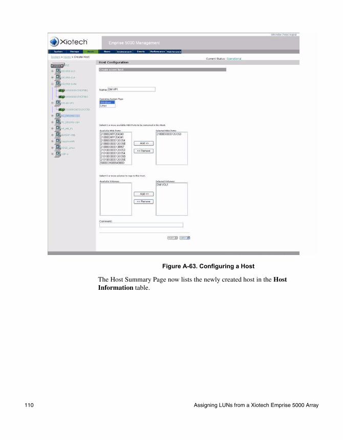
Figure A-63. Configuring a Host
The Host Summary Page now lists the newly created host in the Host Information table.
110 Assigning LUNs from a Xiotech Emprise 5000 Array

Assigning LUNs from a Xiotech Magnitude 3D 4000 Array
To assign LUNs:
1. Perform zoning as follows:
❖ Connect the Fibre Channel ports of the data migration appliance to a switch where the storage controller ports are also logged.
❖ Using switch management tools, create a zone, DM_Host_XiotechMagnitude3D_4000.
❖ In this zone, add the WWPN of the data migration appliance Fibre Channel ports and storage controller ports.
❖ Save the zoning information and activate the new zoning configuration.
2. Launch ICON Manager and log in by typing data in the Hostname (IP address), Username, and Password boxes.
3. In the left pane, expand the Console Root tree, select a DSC, and then click Server View.
4. In the Actions pane on the right, click Add Server.
5. Complete the Add Server Initiator wizard (see Figure A-64) as follows:
❖ On the Welcome window, click Other Server, and then click Continue.
❖ On the Select Initiator window, click FC, and then click Next.
❖ On the Map Host Initiators to Servers window, select the host initiator by WWN, and then under Server Name, type a user-defined name. Then click Next.
Storage Vendor Xiotech Corporation
Array Model Magnitude® 3D 4000 arrays
LUN Assignment Tool ICON Manager 3.3
NoteThe Magnitude 3D 4000 array requires that the ICON Manager 3.3 tool is installed on the host.
Appendix A: Assigning LUNs to the DTA for Data Migration 111

Figure A-64. Mapping Host Initiators to Servers
❖ When the Mapping Servers… window informs you that server mapping is complete, click Next to continue.
❖ On the Configure Another Server Initiator? window, click Yes to configure a second server initiator, or No to stop configuring servers. Then click Next to continue.
❖ On the wizard’s Done window, click Finish.
6. On the Group Servers dialog box, click Close.
7. In the ICON Manager left pane, click Server View.
8. In the middle pane, ensure that the Server View lists the newly created volume.
9. Assign the volume to the initiator as follows:
❖ In the Server View pane, select the newly created volume.
❖ In the Action pane (right pane), click Assign Virtual Disk.
❖ On the Assign Virtual Disk: <volume_name> dialog box, click Browse.
112 Assigning LUNs from a Xiotech Magnitude 3D 4000 Array
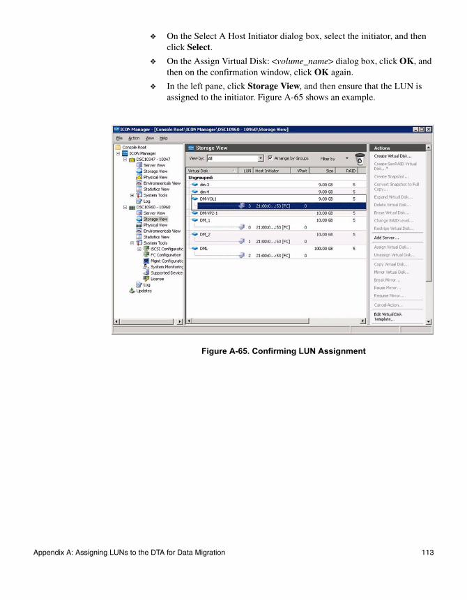
❖ On the Select A Host Initiator dialog box, select the initiator, and then click Select.
❖ On the Assign Virtual Disk: <volume_name> dialog box, click OK, and then on the confirmation window, click OK again.
❖ In the left pane, click Storage View, and then ensure that the LUN is assigned to the initiator. Figure A-65 shows an example.
Figure A-65. Confirming LUN Assignment
Appendix A: Assigning LUNs to the DTA for Data Migration 113

Assigning LUNs from an ETERNUS DX440 Array
To assign LUNs:
1. Perform zoning as follows:
❖ Connect the Fibre Channel ports of the data migration appliance to a switch where the storage controller ports are also logged.
❖ Using switch management tools, create a zone, DM_Host_DX440.
❖ In this zone, add the WWPN of the data migration appliance Fibre Channel ports and storage controller ports.
❖ Save the zoning information and activate the new zoning configuration.
2. In a Web browser, open the ETERNUS SF utility by entering the IP address of the array controller.
3. In the left pane, click Host Interface Management, and then click Set Host Response.
4. In the right pane, click Add Host Response, and then complete the host response information as follows (see Figure A-66):
❖ In the host response Name box, type a user-defined name.
❖ For the Inquiry Standard Data Version, click Version 3.
❖ Accept the default values for all of the remaining parameters.
❖ Click OK to return to the previous window.
❖ Click Set, and then click Confirm to create the host response.
Storage Vendor Fujitsu®
Array Model ETERNUS® DX440 S2 arrays
LUN Assignment Tool ETERNUS SF Storage Cruiser
114 Assigning LUNs from an ETERNUS DX440 Array

Figure A-66. Creating a Host Response
5. Create a host as follows (see Figure A-67):
❖ In the left pane, click a port group.
❖ In the right pane, click Create FC Port Group.
❖ Select the controller adapter and port to which the data migration appliance is connected.
❖ Under CA Port Group Setting, type a user-specified name, and then click Create to create the host group.
NoteA port group determines the front end ports—ports that provide access to the data migration appliance—to be used for a common host configuration.
Appendix A: Assigning LUNs to the DTA for Data Migration 115
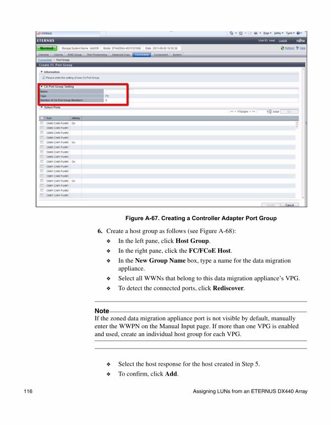
Figure A-67. Creating a Controller Adapter Port Group
6. Create a host group as follows (see Figure A-68):
❖ In the left pane, click Host Group.
❖ In the right pane, click the FC/FCoE Host.
❖ In the New Group Name box, type a name for the data migration appliance.
❖ Select all WWNs that belong to this data migration appliance’s VPG.
❖ To detect the connected ports, click Rediscover.
❖ Select the host response for the host created in Step 5.
❖ To confirm, click Add.
NoteIf the zoned data migration appliance port is not visible by default, manually enter the WWPN on the Manual Input page. If more than one VPG is enabled and used, create an individual host group for each VPG.
116 Assigning LUNs from an ETERNUS DX440 Array
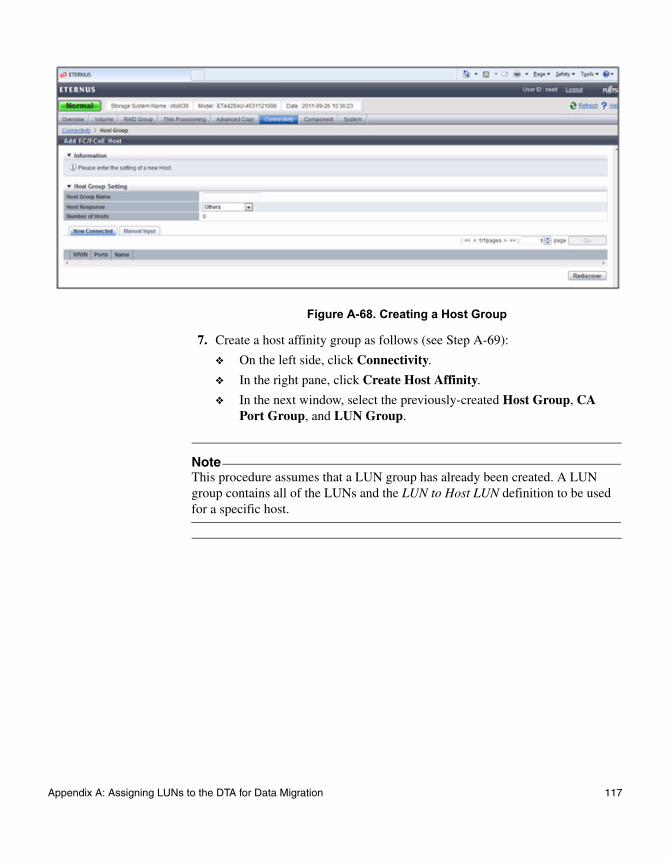
Figure A-68. Creating a Host Group
7. Create a host affinity group as follows (see Step A-69):
❖ On the left side, click Connectivity.
❖ In the right pane, click Create Host Affinity.
❖ In the next window, select the previously-created Host Group, CA Port Group, and LUN Group.
NoteThis procedure assumes that a LUN group has already been created. A LUN group contains all of the LUNs and the LUN to Host LUN definition to be used for a specific host.
Appendix A: Assigning LUNs to the DTA for Data Migration 117
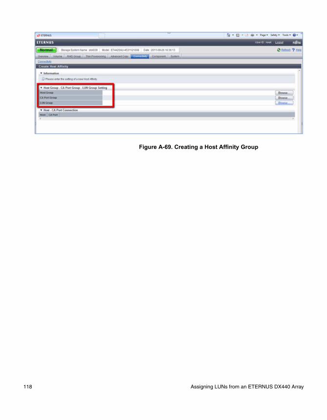
Figure A-69. Creating a Host Affinity Group
118 Assigning LUNs from an ETERNUS DX440 Array

Assigning LUNs from an ETERNUS DX8400 Array
To assign LUNs:
1. Perform zoning as follows:
❖ Connect the Fibre Channel ports of the data migration appliance to a switch where the storage controller ports are also logged.
❖ Using switch management tools, create a zone, DM_Host_DX8400.
❖ In this zone, add the WWPN of the data migration appliance Fibre Channel ports and storage controller ports.
❖ Save the zoning information and activate the new zoning configuration.
2. In a Web browser, open the ETERNUS SF utility by entering the IP address of the array controller.
3. In the left pane, click Host Interface Management, and then click Set Host Response.
4. In the right pane, click Add Host Response, and then complete the host response information as follows (see Figure A-70):
❖ In Host Response Name box, type a user-defined name.
❖ For the Inquiry Standard Data Version, click Version 03.
❖ Accept the default values for all of the remaining parameters.
❖ Click OK to return to the previous window.
❖ Click Set, and then click Confirm to create the host response.
Storage Vendor Fujitsu
Array Model ETERNUS DX8400 arrays
LUN Assignment Tool ETERNUS SF Storage Cruiser
Appendix A: Assigning LUNs to the DTA for Data Migration 119
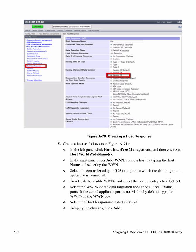
Figure A-70. Creating a Host Response
5. Create a host as follows (see Figure A-71):
❖ In the left pane, click Host Interface Management, and then click Set Host WorldWideName(s).
❖ In the right pane under Add WNN, create a host by typing the host Name and selecting the WWN.
❖ Select the controller adapter (CA) and port to which the data migration appliance is connected.
❖ To refresh the visible WWNs and select the correct entry, click Collect.
❖ Select the WWPN of the data migration appliance’s Fibre Channel ports. If the zoned appliance port is not visible by default, type the WWPN in the WWN box.
❖ Select the Host Response created in Step 4.
❖ To apply the changes, click Add.
120 Assigning LUNs from an ETERNUS DX8400 Array

Figure A-71. Setting the Host WWN
6. Create a host affinity group as follows:
❖ In the left pane, click Host Interface Management, and then click Allocate Host-Infinity Group.
❖ In the right pane under Select a CA, click the port on which the data migration appliance WWPN is available (for which host was created in Step 5), and then click Set (see Figure A-72.)
NoteCreate a separate host for each WWPN of the data migration appliance, and then register each Fibre Channel port of the appliance as a separate host on the array.
Appendix A: Assigning LUNs to the DTA for Data Migration 121

Figure A-72. Allocating a Host Affinity Group
❖ In the right pane, select a WWPN visible on the selected registered host WWN and the Affinity Group to be accessed by the host, and then click Add (see Figure A-73).
Figure A-73. Mapping LUNs
❖ After all needed host WWNs are added, click Set to confirm the additions and map all LUNs in the affinity group to the data migration.
122 Assigning LUNs from an ETERNUS DX8400 Array

NoteThis procedure assumes that the affinity group has already been created for the LUNs directly presented to the host. The same affinity group also presents these LUNs to the data migration appliance.
Appendix A: Assigning LUNs to the DTA for Data Migration 123

124 Assigning LUNs from an ETERNUS DX8400 Array

Index
Numerics3PAR array, assigning LUNs from 42
Aaccess, LUN to server 4active optimized paths, load balancing with 16applications
downtime, minimizing 17server, listing 10
arrayslisting storage 8multipathing software for 9
assigning LUNs for data migrationfrom Data ONTAP 8.0 Cluster-Mode 93from EMC CLARiiON array 60from EMC Symmetrix DMX-4 array 66from ETERNUS DX440 array 114from ETERNUS DX8400 array 119from EVA 4/6/8000 series array 50from HDS array 54from HP 3PAR array 42from IBM DS4K array 70from IBM DS5KL array 70from IBM LSI array 70from MSA2012fc array 35from NetApp Cluster-Mode array 93from NetApp E-Series array 98from NetApp FAS2040 system 78, 82, 85, 88from Xiotech Emprise 5000 array 109from Xiotech Magnitude 3D 4000 array 111
Cconfirming access to data 18controllers, balancing LUNs across 16creating
Fibre Channel zoning 13LUN ID mappings 11
Ddata migration
general steps for 5performance, improving 16
Data ONTAP Cluster-Mode array, assigning LUNs from 93data, validating integrity of 18definitions of terms 2destination arrays
listing 8multipathing software for 9
downtime, minimizing 17dual blade configuration, minimizing downtime with 17
EEMC CLARiiON array, assigning LUNs from 60EMC Symmetrix DMX-4 array, assigning LUNs from 66Emprise 5000 array, assigning LUNs from 109E-Series array, assigning LUNs from 98ETERNUS DX440 array, assigning LUNs from 114ETERNUS DX8400 array, assigning LUNs from 119EVA 4/6/8000 series array, assigning LUNs from 50
Ffabric zones, listing 13FAS2040 system, assigning LUNs from 78, 82, 85, 88Fibre Channel switches, listing 13Fibre Channel zoning, listing 13file system check, validating data 18Fujitsu ETERNUS DX440 array, assigning LUNs from 114Fujitsu ETERNUS DX8400 array, assigning LUNs from 119
Index 125
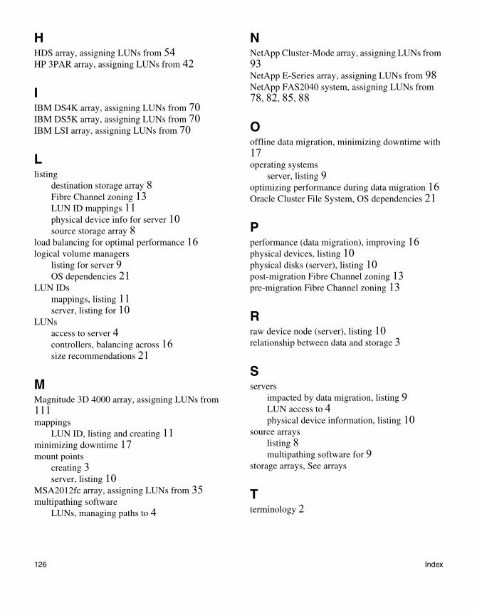
HHDS array, assigning LUNs from 54HP 3PAR array, assigning LUNs from 42
IIBM DS4K array, assigning LUNs from 70IBM DS5K array, assigning LUNs from 70IBM LSI array, assigning LUNs from 70
Llisting
destination storage array 8Fibre Channel zoning 13LUN ID mappings 11physical device info for server 10source storage array 8
load balancing for optimal performance 16logical volume managers
listing for server 9OS dependencies 21
LUN IDsmappings, listing 11server, listing for 10
LUNsaccess to server 4controllers, balancing across 16size recommendations 21
MMagnitude 3D 4000 array, assigning LUNs from 111mappings
LUN ID, listing and creating 11minimizing downtime 17mount points
creating 3server, listing 10
MSA2012fc array, assigning LUNs from 35multipathing software
LUNs, managing paths to 4
NNetApp Cluster-Mode array, assigning LUNs from 93NetApp E-Series array, assigning LUNs from 98NetApp FAS2040 system, assigning LUNs from 78, 82, 85, 88
Ooffline data migration, minimizing downtime with 17operating systems
server, listing 9optimizing performance during data migration 16Oracle Cluster File System, OS dependencies 21
Pperformance (data migration), improving 16physical devices, listing 10physical disks (server), listing 10post-migration Fibre Channel zoning 13pre-migration Fibre Channel zoning 13
Rraw device node (server), listing 10relationship between data and storage 3
Sservers
impacted by data migration, listing 9LUN access to 4physical device information, listing 10
source arrayslisting 8multipathing software for 9
storage arrays, See arrays
Tterminology 2
126 Index

UUNIX OS dependencies 21
Vvalidating data integrity 18volume (server), listing 10
WWindows OS, dependencies with 20WWPNs
listing for FC array 8
listing for zone members 13
XXiotech Emprise 5000 array, assigning LUNs from 109Xiotech Magnitude 3D 4000 array, assigning LUNs from 111
Zzone members, WWPNs for 13zoning, Fibre Channel, listing and creating 13
127 Index

128 Index