dsp tutorial ii - lawrence berkeley national laboratory · objective demonstrate the integrated...
TRANSCRIPT

DSP Tutorial II Real-life Implementation

LLRF 2013 2
Kevin Smith
Tom Hayes
Freddy Severino
Kevin Mernick
Denny Nembhard
Geetha Narayan
Collider-Accelerator Complex

Outline
High-level Algorithm flow
Simulink with XILINX System Generator
Real life example – concept to proof
Demo with HW-SW Co-Simulation
Designs in development
LLRF 2013 3

Survey of System Designers
LLRF 2013 4
©

LLRF 2013 5

Objective
Demonstrate the integrated flow from system design to
implementation of real-time DSP applications on FPGAs
• Use MATLAB / Simulink to validate a simple DSP algorithm
• Implement algorithm with XILINX System Generator
• Verifying the DSP system using Simulink and HDL simulator
• Preparing design for Co-Simulation on SP605 (Spartan-6) Board
• Performing Hardware/Software Co-Simulation for the DSP system
Developers with little FPGA design experience can quickly
create FPGA implementations of DSP algorithms in a fraction
of traditional RTL development times.
6 LLRF 2013
© 2013 Bank of America Corporation

Outline
High-level Algorithm flow
Simulink with XILINX System Generator
Real life example – concept to proof
Demo with HW-SW Co-Simulation
Designs in development
LLRF 2013 7

System Generator Design Flow
LLRF 2013 8

System Generator Features
DSP modeling
Xilinx blockset contains about 100 IPs with functions such as • signal processing (e.g., FIR filters, FFTs)
• error correction (e.g., Viterbi decoder, Reed-Solomon encoder/decoder)
• arithmetic, memories (e.g., FIFO, RAM, ROM), and digital logic
Bit and cycle accurate floating and fixed-point implementation
Automatic code generation of VHDL or Verilog from Simulink • Integrate legacy RTL
Hardware co-simulation
Validate working hardware and accelerate simulations using • Ethernet (10/100/Gigabit)
• JTAG communication between a hardware platform and Simulink
Hardware / software co-design of embedded systems
Build and debug DSP co-processors for the Xilinx MicroBlaze™ soft
processor core
LLRF 2013 9
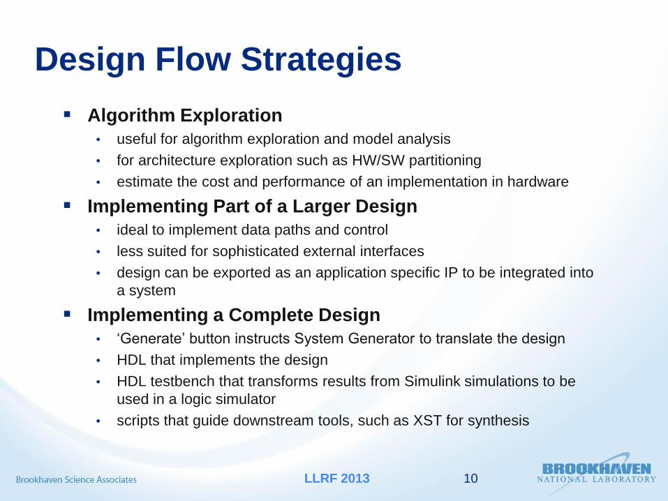
Design Flow Strategies
Algorithm Exploration
• useful for algorithm exploration and model analysis
• for architecture exploration such as HW/SW partitioning
• estimate the cost and performance of an implementation in hardware
Implementing Part of a Larger Design
• ideal to implement data paths and control
• less suited for sophisticated external interfaces
• design can be exported as an application specific IP to be integrated into
a system
Implementing a Complete Design
• ‘Generate’ button instructs System Generator to translate the design
• HDL that implements the design
• HDL testbench that transforms results from Simulink simulations to be
used in a logic simulator
• scripts that guide downstream tools, such as XST for synthesis
10 LLRF 2013

Outline
High-level Algorithm flow
Simulink with XILINX System Generator
Real life example – concept to proof
Demo with HW-SW Co-Simulation
Designs in development
LLRF 2013 11

Coherent Phase Detector for AGS Booster Determine beam bunch phase with respect to net RF voltage per turn in a
Heterodyne System
LLRF 2013 12
LO
DDS
VCO
10.7 ± δ
CAVITY
OUTPUT
MIXER
INPUT
MIXER
INPUT
MIXER
K0
Δφ
FILTER
LO = fRFsys + 10.7 MHz
BEAM PICKUP
fRFbeam
fIF = 10.7 ± δ
fIF = LO - fRFbeam
VSum
WCM
fRFbeam = LO – (10.7 ± δ)
fRFbeam = fRFsys ± δ
FILTER
Phase detector is a main
building block in
loop control applications

Hilbert-transform Phase Detection Scheme
Digital phase detecting method
making use of 90°phase shift
property of Hilbert transform.
• Heterodyne signals are
sampled by A/Ds
• An analytic signal is generated
from a real signal by using the
Hilbert transform
• An FIR filter is used for the
approximation of the Hilbert
transform
• Signals are down-converted to
DC by mixing
• After LPF and decimation
phase difference is computed
LLRF 2013 13

Mathematical Computation Received signals :
s1(t) = a1(t) cos(ωt + Φ1)
s2(t) = a2(t) cos(ωt + Φ2)
Hilbert Transform is equivalent to a 90º phase shift linear filter
H[s1(t)] = a1(t) sin(ωt + Φ1)
H[s2(t)] = a2(t) sin(ωt + Φ2)
Q = s1(t) . H[s2(t)] - H[s1(t)] . s2(t)
= a1(t) . a2(t) . sin(Φ2 – Φ1)
I = s1(t) . s2(t) + H[s1(t)] . H[s2(t)]
= a1(t) . a2(t) . cos(Φ2 – Φ1)
Phase Difference :
Δ Φ = (Φ2 – Φ1) = tan-1(Q ∕ I)
14 LLRF 2013

AGS Phase Detector Simulink Model
LLRF 2013 15
s1(t)
s2(t)
H[s1(t)]
H[s2(t)]
Q
I Δ Φ

Simulink Toolbox & Test Bench
LLRF 2013 16

Xilinx library of bit and cycle-true models
LLRF 2013 17
Basic Elements DSP Blocks

AGS PD System Generator Model
LLRF 2013 18

Video on Firmware Generation (2 min)
19 LLRF 2013

Outline
High-level Algorithm flow
Simulink with XILINX System Generator
Real life example – concept to proof
Demo with HW-SW Co-Simulation
(HW in the Loop)
Designs in development
LLRF 2013 20

HW / SW Co-Simulation
LLRF 2013 21
HW running on SP605
HW / SW interfaces handled
automatically by System Generator

Outline
High-level Algorithm flow
Simulink with XILINX System Generator
Real life example – concept to proof
Demo with HW-SW Co-Simulation
Designs in development
LLRF 2013 22

Bunch-by-Bunch Phase Detector IP
LLRF 2013 23
AD
C
DAC
DACs
Arb WFG
Table
64 KB
X
X
DAC 0 (INSIDE)
Bucket By Bucket
Amplitude Control
Bunch
Tracker
DAC
DAC 1 (OUTSIDE)
Bucket By Bucket
Amplitude Control
Update Link
Master Chassis
ULR
LLRF Drive
Strip Line
Kickers
(Bunch
by
Bunch
Damping)
Bunch By Bunch
Phase Detector
Firmware
BLUE Wall Current
Monitor
PPC
BBD Loop
UL
DACDDS
ULRDDS
Phase
Control
UL
PPC
Program DSP
(Open Loop Frequency Calc)
PPC
Main Beam Control Loop
(Includes Coherent Bunch to
Bucket Phase Loop)
FPGA
FPGA
LLRF Drive
BLUE
Bouncer
(Coherent
Damping)
(BLUE) DAC Daughter Card in Bunch By Bunch Damper Chassis
DAC Daughter Card in YELLOW Bouncer Cavity Controller Chassis
ADC Daughter Card (BTB Phase & Radial Processor)
DACDDS
ULRDDS
Phase
Control
FPGA
DAC Daughter Card in BLUE Bouncer Cavity Controller Chassis
LLRF Drive
YELLOW
Bouncer
(Coherent
Damping)
DAC Daughter Card
BLUE System Controller Chassis
(YELLOW is Identical)
Items in RED highlight the Bunch by Bunch Damper extension to the RHIC LLRF System.
FPGA
FPGA
(Identical
second DAC
card used for
YELLOW Ring)
Ref: Kevin Smith - Overview of LLRF Developments at the
BNL Collider-Accelerator Complex
•Fast feedback bunch phase measurement

Bunch-by-Bunch Phase Detector System
LLRF 2013 24

Building Blocks of DSP Datapath
•NCO Subsystem
• LUT based
•Tunable phase offset
•Generate orthogonal reference signals for down
conversion
•CIC (cascaded integrator comb) Filters
•ideal for large rate changes and narrow band low
pass filtering
•implementation efficient - no multipliers, only
addition and subtraction are needed.
•CORDIC
many functional configurations:
•vector rotation (polar to rectangular),
•vector translation (rectangular to polar),
•Sin and Cos
•Sinh and Cosh
•Atan and Atanh
•Square Root
LLRF 2013 25

CIC Filter Specifications
•Narrow band low pass filter of
consecutive bunches to determine
phase and magnitude
•Bunch train at 9.386 MHz
•Support variable decimation rate R
•Processing clock 100 MHz
•A/D sampling rate 100 Msps
•FPGA resources limited
•Parameterizable Bit Growth
•Resolve inherent memory issues
when time multiplexing bunches
LLRF 2013 26
Implementation
•Single stage CIC sufficient for
phase and magnitude detection
•Throughput meets requirement
•Decimation rate set before comb
stage
•FIFOs to handle accumulator
results from turn to turn
•CIC resource utilization (Virtex5)
•Slice Reg = 200
•BRAM = 1
•DSP48E = 2
Integrator
Comb

Custom 1-Stage CIC filter
LLRF 2013 27

HDL Co-Simulation
• Legacy (or new) HDL code can be
imported into Simulink “black box”
• HDL is co-simulated transparently
using industry-standard simulators
like ModelSim or Active-HDL
• Single HDL simulator for multiple
black boxes
• The time scale in HDL Simulator
matches that in Simulink
LLRF 2013 28

Configuring a HDL Black-Box to import RTL
LLRF 2013 29

Future Development RF BPM Processor
LLRF 2013 30

Software Tools and Versions :
LLRF 2013 31
MATLAB R2011a • Simulink
• DSP System Toolbox
• Signal Processing Design
• Fixed-point Design
• Fixed-point Blocks
ISE Design Suite 13.2 System Edition
Active-HDL 9.2
Demo Platform :
SPARTAN-6 FPGA SP605 Evaluation Kit