dsp input board - rs components
TRANSCRIPT

www.matrixtsl.com EB085
DSP Input Board

2 Copyright © Matrix Technology Solutions Ltd.
Contents
About This Document 2General Information 3Board Layout 4Testing This Product 4Circuit Description 7Circuit Diagram 8
About This Document
This document concerns the E-blocks DSP Input board with code EB085 version 1.
The order code for the DSP Input board product is EB085.
1. Trademarks and copyrightPIC and PICmicro are registered trademarks of Arizona Microchip Inc. E-blocks is a trademark of Matrix Technology Solutions Ltd.
2. DisclaimerThe information provided within this document is correct at the time of going to press. Matrix TSL reserves the right to change specifications from time to time.
• How to get started with E-blocks - if you are new to E-blocks and wish to learn how to use them from the beginning there are resources available to help.
• Relevant software and hardware that allow you to use your E-blocks product better.
• Example files and programs.• Ways to get technical support for your product, either
via the forums or by contacting us directly.
3. Testing this productIt is advisable to test the product upon receiving it to ensure it works correctly. Matrix provides test procedures for all E-blocks, which can be found in the Support section of the website.
4. Product supportIf you require support for this product then please visit the Matrix website, which contains many learning resources for the E-blocks series. On our website you will find:

3 Copyright © Matrix Technology Solutions Ltd.
General Information
1. Description
The DSP Input board allows the exploration of DSP (Digital Signal Processing) style digitally sampled analogue waveforms such as audio or feedback control signals. The board features multiple adjustable amplifier stages, a high speed 16-bit analogue to digital converter ADC, a configurable low pass filter circuit and multiple scope test points so you can monitor the signals at various points in the input chain. The board also has a LED output which detects if the signal is being over amplified and therefore if data is potentially being lost. Using this board it should be possible to configure almost any analogue signal so that it can be read correctly by a microcontroller.
2. Features
• On-board100Ksps16-bitADC• Eightactiveamplifiercircuits• Configurableactivelowpassfiltercircuit• Scopetestpoints• On-boardmicrophone• On-boardmonolineinjack
3. 3.3V System Compatibility
The board is compatible with 3.3V and 5V systems.
4. Block Diagram
On-Board Microphone
Line In
Input Selection Jumper
X10 Gain0.1 - 100 X Gain
Control Pot
Low Pass Filter
Modes Variable
22KHz3.4KHzBypass
Control Pot
On-Board ADC E-blocks
PatchE-blocks
Plug
Clip Detection
LED
Copyright © Matrix Technology Solutions Ltd.4
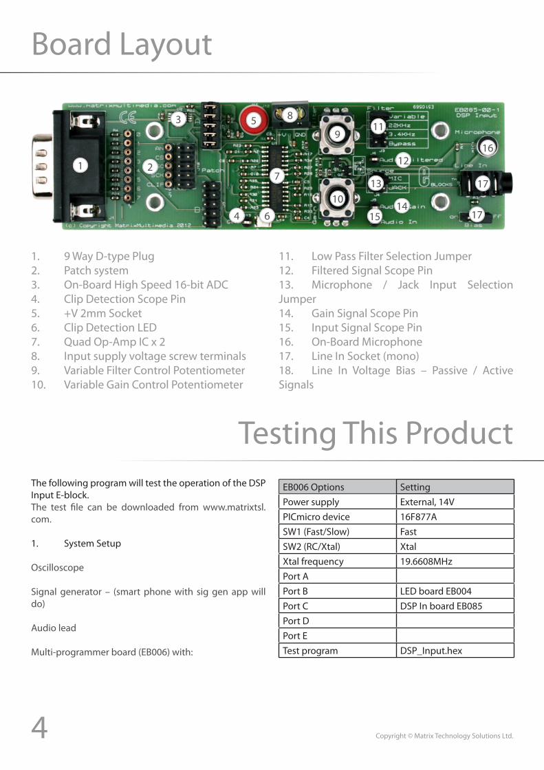
Board Layout
1. 9 Way D-type Plug2. Patch system3. On-Board High Speed 16-bit ADC4. Clip Detection Scope Pin5. +V 2mm Socket6. Clip Detection LED7. Quad Op-Amp IC x 28. Input supply voltage screw terminals9. Variable Filter Control Potentiometer10. Variable Gain Control Potentiometer
11. Low Pass Filter Selection Jumper12. Filtered Signal Scope Pin13. Microphone / Jack Input Selection Jumper14. Gain Signal Scope Pin15. Input Signal Scope Pin16. On-Board Microphone17. Line In Socket (mono)18. Line In Voltage Bias – Passive / Active Signals
Testing This ProductThe following program will test the operation of the DSP Input E-block. The test file can be downloaded from www.matrixtsl.com.
1. System Setup
Oscilloscope
Signal generator – (smart phone with sig gen app will do)
Audio lead
Multi-programmer board (EB006) with:
EB006 Options SettingPower supply External, 14VPICmicro device 16F877ASW1 (Fast/Slow) FastSW2 (RC/Xtal) XtalXtal frequency 19.6608MHzPort APort B LED board EB004Port C DSP In board EB085Port DPort ETest program DSP_Input.hex
1 2
3
4 6
7
5 8
9
10
11
12
13
1415
17
17
16

5 Copyright © Matrix Technology Solutions Ltd.
Testing This Product
1. Ensure that the Multiprogrammer is in correct configuration.- Fast mode (SW1 towards the center of the board).- XTAL mode (SW2 towards the center of the board).- Ensure that a 19.6608MHz crystal is inserted in the Multiprogrammer board.2. Insert the LED board (EB-004-00-1) into Port B of the Multiprogrammer.3. Program the a PIC16F877A with the test program “DSP_Input.hex”.4. Insert the DSP Input board into Port C of the Multiprogrammer jumper settings - B, Bypass, Jack, Off.
5. Connect wire from “+V” of DSP Input board to “+V” of Multiprogrammer.6. Attach scope channel A to the test point Audio In.7. Attach scope channel B to the test pint Audio Gain.8. Connect the signal generator to the phono socket using the audio lead.9. Setthesignalgeneratortooutputa10KHzSinewave at roughly 1V peak to peak.10. Move the Gain potentiometer fully anti clockwise, the output signal should be sat at 2.5V with a peak to peak voltage of around 0V. The Clip LED should be off.
11. Move the Gain potentiometer fully clockwise, the output signal should now go from 0V to 5V in an almost square wave. The Clip LED should appear to be constantly on.
12 . Move scope channel A to the test point Audio Filter.13. Keepingthegainsetfullyclockwise,changethefilterjumpersettingto3.4KHz.
14. Keepingthegainsetfullyclockwise,changethefilterjumpersettingto22.1KHz.

6 Copyright © Matrix Technology Solutions Ltd.
Testing This Product
15. Keepingthegainsetfullyclockwise,changethefilterjumpersettingtovariable,adjustthefilterpotsothatit is fully clockwise.
16. Keepingthegainsetfullyclockwise,adjustthefilterpotsothatitisfullyanti-clockwise.
17. Move scope channel B to the test point Clip.18. The Clip signal should be high whenever the filter signal is in the lower 5% of the voltage range. 0 – 0.5V.
19. Finally remove the scope probes and signal generator.20. Change the input source from Jack to Mic using the jumper.21. Tap the MIC and ensure the Clip LED lights.
22. Tap the MIC and ensure that the LEDs on PortB are changing to match your tapping.23. Reset the potentiometers so they are both full anti clockwise.24. If everything went as listed above then the board has fully passed the test routine.

7 Copyright © Matrix Technology Solutions Ltd.
Circuit Description
1. Description
The circuit board consists of 5 digital I/O lines on a ‘downstream’ 9-way D-type plug. This routes the various signals from the input board to the microcontroller on the ‘upstream’ E-blocks programmer board. The AN signal is the raw analogue signal provided from the E-block. The CS,MISOandSCKpins areused to communicatewiththe on-board ADC IC. The CLIP signal is the same output signal which drives the Clip LED so the microcontroller can warn if portions of the signal are potentially being lost.
SPI based jumper settings:
Jumper Setting A Jumper Setting B PatchPIC16F88 PIC16F877A Any Device
PIC16F1939 Any Device
Individual pin jumper settings:
Pin Function
Jumper Setting A
Jumper Setting B
Patch
AN Bit-0 Bit-1 PatchCS Bit-5 Bit-0 Patch
MISO Bit-1 Bit-4 PatchSCK Bit-4 Bit-3 PatchCLIP Bit-3 Bit-2 Patch
2. ADC Operation
The on-board ADC is a AD7680 IC and can be referenced by using the SPI Legacy component in Flowcode or you can read the analogue signal directly using the ADC module on-board your microcontroller device. There is an example of how to use the SPI component to read the data back from the on-board ADC available as part of the main set of Flowcode examples.
3. Filter Operation
The on-board low pass filter has several operational modes which are selected by moving the jumper on J3. The filter’s response is that so that by the cut-off frequency the signal has been attenuated by 50%. Filtering is important because of an issue when converting analogue signals into digital signals, known as aliasing. If any of the input frequencies are greater than half the sample frequency, the frequency will be misread as a lower frequency. In other words all input frequencies must be less than ½ the sample frequency or aliasing will occur.
• Bypass–Fullbypass,nofilteringisperformedonthe signals.• 3.4KHz – Active filterwith cut-off frequency at3.4KHzallowingforlowqualityphonestyleaudioquality.• 22.1KHz -Activefilterwithcut-off frequencyat22.1KHzallowingforhighqualityCDstyleaudioquality.• Variable – Passive filter with adjustable cut-offfrequencyrangingfromapprox.100KHztoseveralHz.

8 Copyright © Matrix Technology Solutions Ltd.
Circuit Diagram

Matrix Technology Solutions Ltd.The Factory
33 Gibbet StreetHalifax,HX15BA,UK
t: +44 (0)1422 252380e: [email protected]
www.matrixtsl.com
EB085-30-1